Critical Design Review Patrick Weber, Dorin Blodgett, Michael Stephens, Heather Choi, Kevin Brown,...
67
Critical Design Review Patrick Weber, Dorin Blodgett, Michael Stephens, Heather Choi, Kevin Brown, Ben Lampe, Anne-Marie Suriano, Eric Robinson November 19, 2010 11/19/2010 1
-
date post
19-Dec-2015 -
Category
Documents
-
view
214 -
download
0
Transcript of Critical Design Review Patrick Weber, Dorin Blodgett, Michael Stephens, Heather Choi, Kevin Brown,...

1
Critical Design Review
Patrick Weber, Dorin Blodgett, Michael Stephens, Heather Choi, Kevin Brown, Ben Lampe, Anne-Marie Suriano, Eric Robinson
November 19, 2010
11/19/2010

2
Mission Overview
1
2
3
4
5
6
11/19/2010 Presenter: Eric Robinson

3
Mission Overview
Scientific Mission o Primary: Collect space dust.
o Provide a perspective of what is in our upper atmosphere.
o Particle size = nano and micro level
o Donate collected aerogel tablets to UW Geology Department for further analysis
o SEM photographs of particle trails – velocity analysis
o Identify particles – material property analysis
o Secondary:o Capture optical images/video of the Earth.
o Measure thermal and seismic effects throughout the duration of the launch.o Collect data for future projects.
Presenter: Eric Robinson11/19/2010

4
Mission Overview
Engineering Missiono Engineer an extendable boom to mount a dust collector.
o Use aerogel and acrylic tablets as dust collectors.o Aerogel Density = 95 kg/m3
o Acrylic Density = 1200 kg/m3
o Engineer a water shield to protect dust collector.
o Engineer modular electronic systems for:o Capturing and storing images from optical devices.
o Recording thermal and seismic data in real time throughout launch using sensors and transferring recording data via provided NASA Wallops Telemetry.
Presenter: Eric Robinson11/19/2010
5
Mission Overview
Organizational Chart
Presenter: Eric Robinson
Project ManagerShawn Carroll
Team LeaderPatrick Weber
Physics Faculty AdvisorDr. Paul Johnson
Engineering Faculty AdvisorDr. Carl Frick
Integrated Sensors (IS)Michael Stephens
Heather Choi
Electrical Power System (EPS)Michael Stephens
Ben Lampe
Telescopic Boom (TB)Patrick WeberEric RobinsonDorin Blodgett
Optical Camera (OC)Kevin BrownNick Roder
Charles Galey
11/19/2010

6
Mission Overview
Theory and Conceptso Underlying Science and Theory
o Attempt to capture space particles using telescoping boom, aerogel, and acrylic discs.
o Quantification of varying flight parameters.
Presenter: Eric Robinson11/19/2010
7
Mission Overview
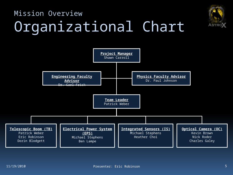
Theory and Conceptso Previous Experimentation
o Previous flights have included multi-sensor packages.
o Temperature, Humidity, and Pressure Sensors
o Accelerometers / Seismic Sensors
o Magnetometers
o Data Storage (SD Cards)
o Results provided a basis for improvement on future data collection and retrieval.
o SD Cards impervious to low exposure to salt water
o Payload electrical orientation
Presenter: Eric Robinson11/19/2010

8
Mission Overview
Concept of Operations
Presenter: Eric Robinson
t ≈ 0 minLaunch
Systems Power On (t = -2 min)-Collection of Sensor Data Begins
t ≈ 0.7 minEnd of Orion Burn
t ≈ 1.7 minShedding of Skin
Boom Extends via First Timed Eventt ≈ 2.8 min
Apogee
t ≈ 4.0 minBoom Retracts via Arduino Controller
Boom Power Shut Down
t ≈ 8.2 minChute Deploys
t ≈ 15 minSplash Down
Payload Power Down
11/19/2010

9
Mission Overview
Expected Resultso Successfully collect space dust
o Space Dust Composition (10-6)
o Exhausted Rocket Fuel
o Meteor / Metal Fragments
o Other Miscellaneous Gases
o Detailed data throughout flight duration
o Thermal Data
o Seismic/Vibration Data
o Earth images/video
Presenter: Eric Robinson11/19/2010

10
Design Description
1
2
3
4
5
6
11/19/2010 Presenter: Eric Robinson
11
Design Description
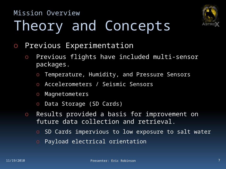
Design Changes Since PDRo Payload water shield has been removed
o Complex manufacturability
o Electrical components do not need to be salvaged
o New Telescopic Boom Control Mechanismo Steel tape reel design (akin to a tape measure)
o New high torque gear box DC motor instead of stepper motor
o Mission Objective Changeso Pressure sensors have been removed from secondary objective
Presenter: Eric Robinson11/19/2010

12
Design Description
De-Scopes and Off-Rampso De-Scopes
o No mission objectives have been removed
o All objectives are still considered feasible
o Off-Rampso We do not believe we will run into schedule/budget constraints
that would require a contingency.
11/1/2010 Presenter: Eric Robinson

13
Design Description
Subsystem Overview
11/1/2010 Presenter: Eric Robinson
MCU Arm Control
Temp. Sensor
Optical Camera
PWR
Wallops Telemetr
y
Wallops
EPS
EPS/STR Interface OC/STR
Interface
TB/STRInterface
TB/EPSInterface
OC/EPSInterface
STR
TB OC
BoomAerogel
Motor
Boom
IS IS/EPSInterface
IS/STR Interface
Temperature Sensor
Accelerometers
Optical Camer
a
Optical Camera
Accel.Sensor
Control Box

14
Design Description
Mechanical Design Elements
11/1/2010 Presenter: Eric Robinson

15
Design Description
Mechanical Design Elements
11/1/2010 Presenter: Eric Robinson

16
Design Description
Mechanical Design Elements
11/1/2010 Presenter: Eric Robinson
o Retracted – 11 in boom
o Extended – ~19 in boom – ~12 in reach

17
Design Description
Electrical System : Componentso Arduino Controller
o 5M Digital Camera
o 16 Mbit data flash
o 100:1 Metal gear motor
o 250 G Accelerometer
11/1/2010 Presenter: Michael Stephens
o 16G 2-Axis Accelerometer
o Temperature Sensors
o Motor Driver
o Encoders
o Power Regulators

18
Design Description
Electrical System : Arduinoo Atmega 328 @ 16 MHz
o 32Kb of Program Storage
o 2KB of Ram
o Digital Pins : 14o 6 PWM
o Analog Pins : 6 o 10 Bit
o 10 KHz sample time
o Provide control over payload11/1/2010 Presenter: Michael Stephens

19
Design Description
Electrical System : XY Accel.o 2 axis ± 18G
o 36 / (2^10) = 0.03515625 G Resolution @ 10 bit
o 5V @ 350 µA
o 50 Hz cut off filter
o Used last year as well
o Provide acceleration in the non extreme XY axis.
11/1/2010 Presenter: Michael Stephens

20
Design Description
Electrical System : Z Accel.o 1 axis ± 250 G
o 500 / (2^10) = 0.48828125 G resolution @ 10 bit
o 5V @ 1.5 mA
o 400 Hz cutoff filter
o Provide acceleration data in the extreme Z (up) axis
11/1/2010 Presenter: Michael Stephens

21
Design Description
Electrical System : Motoro 100:1 gear ratio
o 140rpm @ 6V
o 6V @ 90mA
o 800mA stall current @ 6V
o 0.9375 in-lb motor torque @ 6V
o Provide winding action of tape.
11/1/2010 Presenter: Michael Stephens

22
Design Description
Electrical System : Motor Drivero 3 wire interface (In1, In2, PWM)
o 1.2 A max @ 15 V
11/1/2010 Presenter: Michael Stephens

23
Design Description
Electrical System : Temp. Sensoro TMP36
o -50C to 125C = 175C range
o 175 / (2^10) = 0.170898438 degree resolution @ 10 bits
o SLOW (300s for full range change)
o 5V @ .5uA
11/1/2010 Presenter: Michael Stephens

24
Design Description
Electrical System : Optics
DVR 623V 5M DSC/DV module
o 5.1 megapixel
o Internal shutter trigger
o SD Data up to 4GB
o 5V @ ? mA
o Provide photos/video of flight
11/1/2010 Presenter: Michael Stephens
25
Design Description
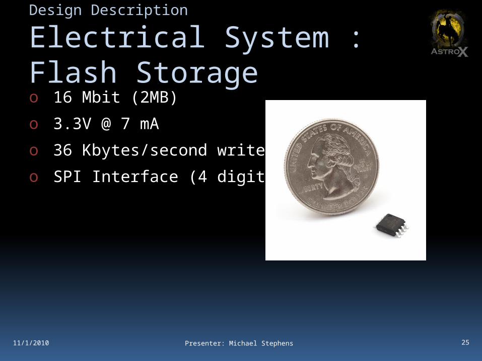
Electrical System : Flash Storageo 16 Mbit (2MB)
o 3.3V @ 7 mA
o 36 Kbytes/second write time
o SPI Interface (4 digital pins)
11/1/2010 Presenter: Michael Stephens
26
Design Description
Electrical System : Storageo Used for redundant storage of acceleration data
o Maximum sensor sampling time 400 Hz
o 3 x 10 bit = 30 bits ~ 4 bytes
o (((16 000 000 / 8) / 4) / 400) / 60 = 20.8333333 minutes of recording time.
11/1/2010 Presenter: Michael Stephens

27
Design Description
Electrical System : Powero 12 V regulators
o 6V regulators
o 780X series max input voltage 35 volts.
11/1/2010 Presenter: Michael Stephens

28
Design Description
Electrical System : Encodero Digital light sensor
o 2 Wires (1 enable, 1 output)
o 5V @ 25 mA
o Used to sense black and white pattern on spool.o Used to detect stalls
o Used to verify extension
11/1/2010 Presenter: Michael Stephens

29
Design Description
Electrical System : Telem. IF
11/1/2010 Presenter: Michael Stephens

30
Design Description
Electrical System : Power IF
11/1/2010 Presenter: Michael Stephens

31
Design Description
Software Design Elements
11/1/2010
o Programmed on Arduino in “C”
o Heavy use of interrupts
Presenter: Michael Stephens

32
Design Description
Software Design Elements
11/1/2010 Presenter: Michael Stephens

33
Prototyping/ Analysis
1
2
3
4
5
6
11/19/2010 Presenter: Patrick Weber
34
Analysis Results
o Telescopic Boomo Finite Element Analysis
o Deflections, stress, and strain
o Newtonian Laws
o Payload Frameo Finite Element Analysis
o Deflections, stress, and strain
11/1/2010 Presenter: Patrick Weber
35
Analysis ResultsTelescopic Boom - Stress
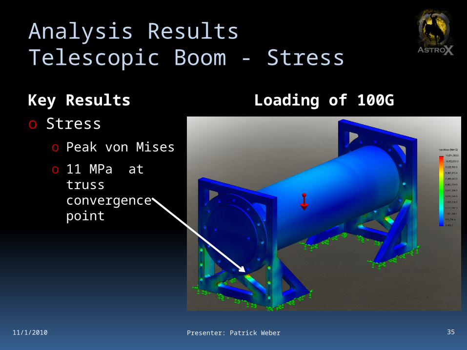
Key Resultso Stress
o Peak von Mises
o 11 MPa at truss convergence point
Loading of 100G
11/1/2010 Presenter: Patrick Weber

36
Analysis ResultsTelescopic Boom – Deflection
Key Resultso Deflection
o 6061 Aluminum
o 1.12E-2 mm at
o center of boom.
o 1023 Carbon Steel
o 1.099E-2 mm at
o center of boom.
Loading of 100G
11/1/2010 Presenter: Patrick Weber

37
Analysis ResultsTelescopic Boom – FOS
Key Resultso Factor of Safety
o 6061 Aluminum
o Min - 24.59
o 1023 Carbon Steel
o Min – 8.59
Loading of 100G
11/1/2010 Presenter: Patrick Weber

38
Analysis ResultsMaterial Decisiono Material Strength
o Results showed that both materials could handle the loadings with minimal deflection
o Material densityo Aluminum 6061
o ρ = 0.0975 lb/cu.in.
o 1023 Carbon Steel
o ρ = 0.284 lb/cu.in.
o Therefore 6061 Aluminum Alloy will be the chosen as the material for our mechanical components.
11/1/2010 Presenter: Patrick Weber

39
Analysis ResultsMaterial Decisiono Aerogel Design
o Results from aerogel studies have proven that an Aerogel Density of 95 kg/m3 will be sufficient in capturing the micro-scaled particles. [1]
o [1] – Horz, Friedrich, Mark J. Cintala, Thomas H. See, and Keiko Nakamura-Messenger. "Penetration Tracks in Aerogel. Produced by Al2O3 Spheres." Meteoritics & Planetary Science.
11/1/2010 Presenter: Patrick Weber

40
Prototyping Results
o Most prototyping is theoretical and conducted using SolidWorks.
o Further prototyping and testing will occur once the parts are manufactured and assembled.o Late January/Early February
11/1/2010 Presenter: Patrick Weber

41
Detailed Mass Budget
o Total Mass Budget (15±0.5 lbs)o Structure (5.95 lbs)
o Boom (5.05 lbs)
o Circuit Trays (0.9 lbs)
o Camera (0.25 lb)
o Other Sensors (1 lb)
o Modular Electrical System (1 lb)
o Ballasting (~6.80 lbs)
Presenter: Patrick Weber
Mass Budget
Boom Circuit TraysCamera Other SensorsModular Electrical System Ballasting
11/19/2010

42
Detailed Power Budget
Presenter: Michael Stephens11/19/2010
o Redundant Power (2,3) @ T0 launch (17%)
o Event Power (4) @ T+5 shield ejection (80%)
Source Consumption (in Amps)Arduino 0.02Encoder 0.025Camera 0.1
Temp Sensors 0.0000015XY Acc 0.000335Z Acc 0.0015
Motor Driver 0.025Total 0.1718365
Source Consumption (in Amps)Motor 0.8Total 0.8
43
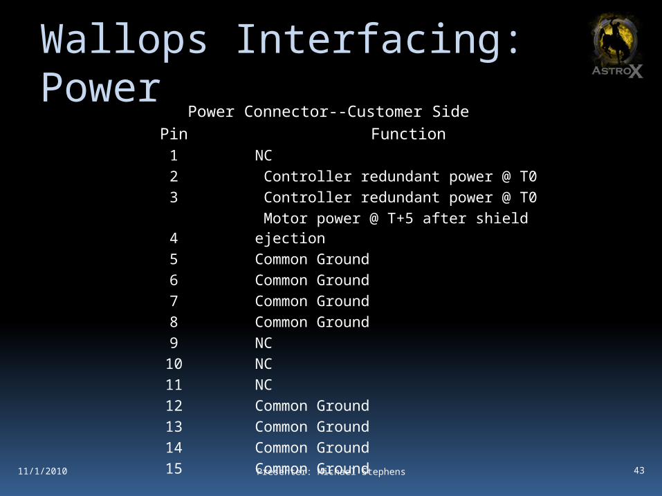
Wallops Interfacing: Power
11/1/2010 Presenter: Michael Stephens
Power Connector--Customer SidePin Function1 NC2 Controller redundant power @ T03 Controller redundant power @ T04 Motor power @ T+5 after shield ejection5 Common Ground6 Common Ground7 Common Ground8 Common Ground9 NC
10 NC11 NC12 Common Ground13 Common Ground14 Common Ground15 Common Ground
44
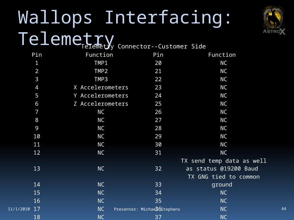
Wallops Interfacing: Telemetry
11/1/2010 Presenter: Michael Stephens
Telemetry Connector--Customer SidePin Function Pin Function1 TMP1 20 NC2 TMP2 21 NC3 TMP3 22 NC4 X Accelerometers 23 NC5 Y Accelerometers 24 NC6 Z Accelerometers 25 NC7 NC 26 NC8 NC 27 NC9 NC 28 NC
10 NC 29 NC11 NC 30 NC12 NC 31 NC
13 NC 32 TX send temp data as well as status
@19200 Baud14 NC 33 TX GNG tied to common ground15 NC 34 NC16 NC 35 NC17 NC 36 NC18 NC 37 NC19

45
Manufacturing Plan
1
2
3
4
5
6
11/19/2010 Presenter: Patrick Weber

46
Manufacturing Plan
Mechanical Elementso Payload Frame – 6061 Aluminum Alloy
o Machined
o Bolted together
o Telescopic Boom – Precision DOM Aluminum Tubingo Boom Housing
o Tubing with Epoxied Flange
o Intermediate Arm
o Epoxied Rail
o Aerogel Arm
o CNC machined from Aluminum Barstock
o Aerogel Purchased
o Parts submitted for machining by Tuesday, November 23rd
11/1/2010 Presenter: Patrick Weber

47
Manufacturing Plan
Electrical Elementso Electrical Power System
o Arduino Board
o Integrated Sensorso Purchase
o All wires will be soldered
o All wires and boards will be epoxied to acrylic mounting plates.o Acrylic will comply with no-voltage requirement.
o Parts ordered by Wednesday, December 1st.
11/1/2010 Presenter: Michael Stephens

48
Manufacturing Plan
Software Elementso Software will be developed next semester starting mid-
January 2011.
o Software will be developed in modules and integrated as a whole as they become functional.
Software developed in Arduino “C” language.
11/1/2010 Presenter: Patrick Weber

49
Testing Plan
1
2
3
4
5
6
11/19/2010 Presenter: Patrick Weber

50
Testing Plan
System Level Testingo Full mission simulation testing using physical model.
o Vibration testing at the University as well as Wallops.
o Boom extension/retraction test using electronics and mechanical models.
o Payload drop testing
o Thermal Expansion testing
11/1/2010 Presenter: Patrick Weber

51
Testing Plan
Mechanical Testingo Prove mechanical functionality on ground
o Boom testso Cyclic Extension/Retraction Tests
o Friction Tests
o Bending/Binding Tests
o Tape Reel Buckling Strength Tests
o Thermal Expansion Tests
o Water sealant testingo Pool submersion test on canister
o Drop impact test on canister sealing
o Testing will be performed as models and utilities become available.
11/1/2010 Presenter: Patrick Weber

52
Testing Plan
Electrical Testingo Temperature sensor testing
o Measure sensors 24 hours a day and correlate with other temperatures measurements.
o Place sensor unit in oven until reading stabilizes. Remove sensor and place outside at night until reading stabilizes. Do this multiple times to determine time delay.
o Hot / Cold system testo Place entire system in oven, place outside. Examine for solder
disconnects.
o Accelerometer testingo Use elevators and cars to verify acceleration readings.
11/1/2010 Presenter: Michael Stephens

53
Testing Plan
Software Testingo Asynchronous data capture test
o Run Sine wave into ADC. Verify consistent timing.
o Motor control testo Extend boom
o Retract boom
o Verify extension and retraction and analyze fault conditions
o Integration testingo Use sine wave generators as sensor inputs
o Run simulated mission to detect possible data anomalies / control anomalies.
o Multiple day in the life (DITL) tests on ground. o Simulate entire mission with actual sensors.
11/1/2010 Presenter: Michael Stephens

54
Risks
1
2
3
4
5
6
11/19/2010 Presenter: Patrick Weber

55
Risk Walk-Down
o Risk Matrix / Mitigationo STR/TB.RSK.1: Canister seals fail
at splashdown and aerogel issaturated with water.
o TB.RSK.2: Boom jams when skinsare shed. Boom fails to open andmission objectives are not met.
o IS.RSK.1: Telemetry or flash memoryfail and data to be collected for next year’s team is lost. Secondary mission objectives are not met.
o EPS.RSK.1: Should the NASA telemetry or Timed Event circuits fail, the boom may prematurely extend causing failure of the UW payload as well as possible damage to the rocket.
Presenter: Patrick Weber
Consequence
EPS.RSK.1 STR/TB.RSK.1TB.RSK.2
IS.RSK.1
Possibility
11/19/2010

56
User Guide Compliance
1
2
3
4
5
6
11/19/2010 Presenter: Patrick Weber

57
User Guide Compliance
11/19/2010
Requirement Status/Reason (if needed)Center of gravity in 1" plane of
plate? Unsure
Max Height < 12" In compliance
Within Keep-Out In compliance
Using < 10 A/D Lines In compliance
Using/Understand Parallel Line In compliance
Using/Understand Asynchronous Line 19200 Baud
Using X GSE Line(s) Not at this time
Using X Redundant Power Lines 1
Using X Non-Redundant Power Lines 1
Using < 1 Ah 0.152Ah total (all lines)
Using <= 28 V 3.3V - 12V
Presenter: Patrick Weber

58
Sharing Logistics
o Who are we sharing with? – We don’t know.o University of Northern Colorado
o Re-entry Experiment Sat: Recover a reusable deployable, attempt to dynamically control the descent of the payload, and gather data during the return trip.
o The possibility of a communication system between the AstroX payload and the UNC Re-entry Experiment Sat payload is being considered.
o Plan for collaboration?o Email, phone, road-trips to Greeley and Boulder
o Communication with Max Woods on a weekly basis.
o Grant UNC access to the AstroX private website.
11/19/2010 Presenter: Patrick Weber

59
Project Management Plan
1
2
3
4
5
6
11/19/2010 Presenter: Patrick Weber

60
Mechanical Schedule
o Major Mechanical Milestones:o Design Freeze at CDR (Friday, November 19, 2010)
o Blueprints submitted for manufacturing on Nov. 23
o Mechanical prototype constructed mid-January, 2011
o Mechanical prototype fully tested by end of January, 2011
o Impact and submersion testing
o Aerogel testing
Presenter: Patrick Weber11/19/2010
61
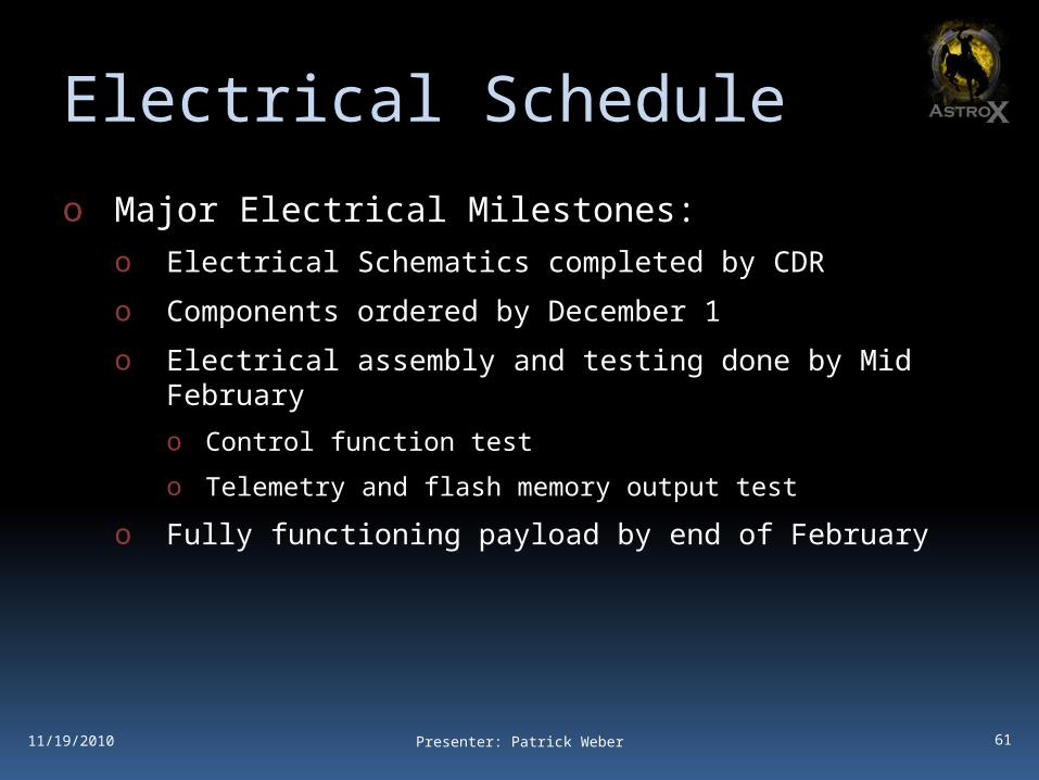
Electrical Schedule
o Major Electrical Milestones:o Electrical Schematics completed by CDR
o Components ordered by December 1
o Electrical assembly and testing done by Mid February
o Control function test
o Telemetry and flash memory output test
o Fully functioning payload by end of February
Presenter: Patrick Weber11/19/2010

62
Monetary Budget
o Monetary Budget (~$1200)o Structure ($600)
o Boom ($300)
o Aerogel ($300)
o Camera ($100)
o Other Sensors ($110)
o Modular Electrical System ($200)
o Correcting Factor (+$20%)
Presenter: Patrick Weber
Monetary Budget
Boom CameraOther Sensors Modular Electrical SystemAerogel Correcting Factor
11/19/2010

63
Work Breakdown Structure
Presenter: Patrick Weber
Integrated Sensors (IS)
Electrical Power System (EPS)Telescopic Boom (TB)
Optical Camera (OC)
• Design Freeze at CDR• Submit Work Request• Manufacture Boom Parts• Assemble Boom and Structure
• Design Freeze at CDR• Order Parts by End of Fall Semester• Build Circuits• Program Microcontrollers• Test Systems• Integrate with Boom
• Design Freeze at CDR• Order Parts by End of Fall Semester• Build Circuits• Program Microcontrollers• Test Systems
• Test functionality of camera• If functional:
• Integrate with Electrical Power System and Integrated Sensors
• If non-functional:• Order another camera
11/19/2010

64
Conclusions
1
2
3
4
5
6
11/19/2010 Presenter: Patrick Weber
65
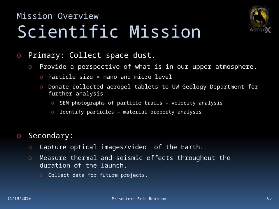
Mission Overview
Scientific Mission o Primary: Collect space dust.
o Provide a perspective of what is in our upper atmosphere.
o Particle size = nano and micro level
o Donate collected aerogel tablets to UW Geology Department for further analysis
o SEM photographs of particle trails – velocity analysis
o Identify particles – material property analysis
o Secondary:o Capture optical images/video of the Earth.
o Measure thermal and seismic effects throughout the duration of the launch.o Collect data for future projects.
Presenter: Eric Robinson11/19/2010
66
Mission Overview
Engineering Missiono Engineer an extendable boom to mount a dust collector.
o Use aerogel and acrylic tablets as dust collectors.o Aerogel Density = 95 kg/m3
o Acrylic Density = 1200 kg/m3
o Engineer a water shield to protect dust collector.
o Engineer modular electronic systems for:o Capturing and storing images from optical devices.
o Recording thermal and seismic data in real time throughout launch using sensors and transferring recording data via provided NASA Wallops Telemetry.
Presenter: Eric Robinson11/19/2010

Questions?