Critical Design Review - NASA · - Index of plant “greenness” or photosynthetic ... - 2010 NOA...
117
RockSat-C 2014 CDR WV Rocketeers Critical Design Review WVU WVU-TECH FSC SU MU WVWC JFFL NASA IV&V Steven Hard, Zack Dixon, Greg Lusk, Rachelle Huff, Seth Baker, Andrew Tiffin 12/4/2014 1
Transcript of Critical Design Review - NASA · - Index of plant “greenness” or photosynthetic ... - 2010 NOA...

RockSat-C 2014 CDR
WV Rocketeers Critical Design Review
WVU WVU-TECH FSC SU MU WVWC JFFL NASA IV&V Steven Hard, Zack Dixon, Greg
Lusk, Rachelle Huff, Seth Baker, Andrew Tiffin
12/4/2014
1

RockSat-C 2014 CDR
CDR Presentation Content
2
• Section 1: Mission Overview – Mission Overview – Organizational Chart – Theory and Concepts – Concept of Operations – Expected Results
• Section 2: Design Description – Requirement/Design Changes Since CDR – De-Scopes/Off-Ramps – Mechanical Design Elements – Electrical Design Elements

RockSat-C 2014 CDR
CDR Presentation Contents
3
jessicaswanson.com
• Section 3: Prototyping/Analysis – Analysis Results
• Interpretation to requirements – Prototyping Results
• Interpretation to requirements • Section 4: Manufacturing Plan
– Mechanical Elements – Electrical Elements – Software Elements

RockSat-C 2014 CDR
CDR Presentation Contents
4
• Section 5: Testing Plan – System Level Testing
• Requirements to be verified – Mechanical Elements
• Requirements to be verified – Electrical Elements
• Requirements to be verified – Software Elements
• Requirements to be verified • Section 6: System Level Design
– Detailed Mass Budget – Detailed Power Budget – Detailed Interfacing

RockSat-C 2014 CDR
CDR Presentation Contents
5
• Section 7: Risks – Risks from PDR to CDR
• Walk-down – Critical Risks Remaining
• Section 8: User Guide Compliance – Compliance Table – Sharing Logistics
• Section 9: Project Management Plan – Schedule – Budget
• Mass • Monetary
– Work Breakdown Structure

RockSat-C 2014 CDR
Mission Overview Steven Hard
6
RockSat-C 2014 CDR
Mission Overview
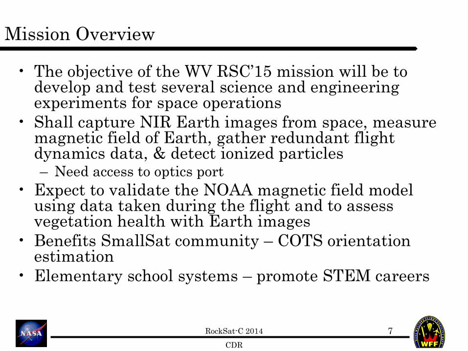
• The objective of the WV RSC’15 mission will be to develop and test several science and engineering experiments for space operations
• Shall capture NIR Earth images from space, measure magnetic field of Earth, gather redundant flight dynamics data, & detect ionized particles – Need access to optics port
• Expect to validate the NOAA magnetic field model using data taken during the flight and to assess vegetation health with Earth images
• Benefits SmallSat community – COTS orientation estimation
• Elementary school systems – promote STEM careers
7

RockSat-C 2014 CDR
Expected Results: WVU-CAM
• Sequence of 60 second video clips throughout entire flight and payload recovery
• Extraction of “good” images from video data during flight - Good: visibly distinguishable land mass or NIR source
• Expect to create a Normalized Difference Vegetation Index (NDVI) of reflected NIR light intensities (from 0.7 to 1.1 µm) for each good image
- Index of plant “greenness” or photosynthetic activity • Visual telemetry showing evidence of any faults experienced during flight
10

RockSat-C 2014 CDR
Expected Results: NIR-NDVI
9
RockSat-C 2014 CDR
Expected Results: SPACE (4x)
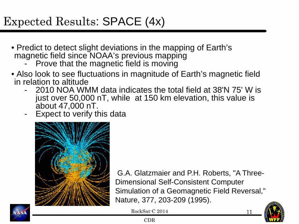
• Predict to detect slight deviations in the mapping of Earth’s magnetic field since NOAA’s previous mapping
- Prove that the magnetic field is moving • Also look to see fluctuations in magnitude of Earth’s magnetic field in relation to altitude
- 2010 NOA WMM data indicates the total field at 38'N 75' W is just over 50,000 nT, while at 150 km elevation, this value is about 47,000 nT.
- Expect to verify this data
11
G.A. Glatzmaier and P.H. Roberts, "A Three-Dimensional Self-Consistent Computer Simulation of a Geomagnetic Field Reversal," Nature, 377, 203-209 (1995).

RockSat-C 2014 CDR
Expected Results: SPACE (4x)
• Comparison of COTS IMU performance with high resolution IMU
• Increased radiation levels with altitude - This radiation will be measured in terms of keV (kilo electron
volts) - Expect that the radiation will be between .09-2.5 KeV in the E
layer and 1-20 KeV in the D layer • Detection of cosmic rays near apogee
11

RockSat-C 2014 CDR
Concept of Operations
12
H = 0 km (T = 0) Launch
H = 115km (T = 2.8 min) Apogee
H = 10.5 km (T = 5.5 min) Chute deploys
H = 0 km (T = 15 min) Splashdown
H = 11 km (T = 5.3 min) Boom retraction triggered
H = 52 km (T = 0.6 min) End of Orion Burn
H = 0 km (T = -3 min) All systems on Begin data acquisition
H = 75 km (T = 1.3 min) Boom extension triggered
H = 1.5 km (T = 2.3 sec) Atmospheric Port valve open H = 1.5 km (T = 2.3 sec)
Atmospheric Port valve closed

RockSat-C 2014 CDR
Organizational Chart
13
Project Manager Steven Hard
Integration Engineer Greg Lusk
WVWC Faculty Advisor Dr. Tracey DeLaney
Marshall Sponsor Dr. Jon Saken
Shepherd Faculty Advisory
Dr. Ralph Wojtowicz
WVU-CAM Steven Hard WVU Team
(3 Total)
WVWC-SPACE Andrew Tiffin
WVWC Team ‘ (3 Total)
Shepherd-SPACE Rachelle Huff
Shepherd Team (2 Total)
WVUTECH-SPACE Zack Dixon
WVU-Tech Team (3 Total)
WVU Faculty Advisor Dr. Dimitris Vassiliadis
WVU-TECH Faculty Advisor
Dr. Farshid Zabihian
Marshall-SPACE Seth Baker
Marshall Team (5 Total)
Mechanical Engineering Alex Flores

RockSat-C 2014 CDR
Project Management: Marshall U

RockSat-C 2014 CDR
WVWC-SPACE Design Description
Andrew Tiffin Eric Kramer

RockSat-C 2014 CDR
WVWC-SPACE: Design Modifications
• We will be removing the altimeter from our project, due to limitations of our sensor.

RockSat-C 2014 CDR
WVWC-SPACE: De-Scopes and Off-Ramps
• We have decided that the altitude sensor we were planning to use will not work at such extreme altitudes, because it is designed to be used at ground level altitudes (<28000 feet)
• Final PCB design to fit CubeSat specs is an off-ramp in case development is behind schedule

RockSat-C 2014 CDR
WVWC-SPACE: Electrical Design Elements
• We plan to use two PCB boards; one for our magnetometer and one for our Geiger counter.
• We will use stand-off tabs to mount the Geiger counter PCB above the magnetometer on the main PCB.

RockSat-C 2014 CDR
WVWC-SPACE: Electrical Diagram

RockSat-C 2014 CDR
WVWC-SPACE: Electrical Schematic

RockSat-C 2014 CDR
WVWC-SPACE: Software Design Elements

RockSat-C 2014 CDR
WVWC-SPACE: Magnetometer Code

RockSat-C 2014 CDR
WVWC-SPACE Prototyping/Analysis
Andrew Tiffin
23

RockSat-C 2014 CDR
WVWC-SPACE: Analysis Results
• We have decided that the Geiger counter will be mounted above the magnetometer.
• We also are planning to build a new PCB for the magnetometer which will be 4”X 4” and will cut notches into board so it will be design ready for IOS CubeSat orbital launch.

RockSat-C 2014 CDR
WVWC-SPACE: Prototyping Results

RockSat-C 2014 CDR
WVWC-SPACE Manufacturing Plan
Eric Kramer
26

RockSat-C 2014 CDR
WVWC-SPACE: Mechanical Elements
• Stand-off mounting hardware still needs to be built.
• This can be built in the first few weeks after returning to school in January.

RockSat-C 2014 CDR
WVWC-SPACE: Electrical Elements
• Leads from the Geiger counter still need to be connected to the Arduino Mini on the PCB.
• We will also be designing a new PCB board with larger dimensions and traces for Geiger counter connection.

RockSat-C 2014 CDR
WVWC-SPACE: Software Elements
• The code for the Geiger counter still needs to be written to record the short pulses, which is the count rate.
• This will be worked on over Christmas break.

RockSat-C 2014 CDR
WVWC-SPACE Testing Plan
Steven Hard
30

RockSat-C 2014 CDR
WVWC-SPACE: Electrical Testing
• The Geiger counter will be tested against another calibrated Geiger counter that is already on hand.
• Magnetometer will be tested using the known magnetic field in our region.
• Results will verify functional requirements of each subsystem
• Sensor Calibration: 1/19/15 – 2/6/15

RockSat-C 2014 CDR
WVWC-SPACE: Software Testing
• Testing the Geiger counter will involve recording the count rate with our sensor and then comparing to a calibrated Geiger counter.
• Testing the Magnetometer will involve measuring the output magnetic readings and comparing to the known magnetic field in our region.
• Software Verification: 12/20/15 – 1/23/15

RockSat-C 2014 CDR
WVUTech-SPACE Design Description
Zack Dixon
33

RockSat-C 2014 CDR
WVUTech-SPACE: Off-Ramps and De-scopes
• High risk design parameter is PCB implementation
• Plan is to order PCB early enough to have revisions made
• Off-ramp is to design functional PCB first and modify to fit CubeSat specs for final revision
34

RockSat-C 2014 CDR
WVUTech-SPACE: Electrical Design Elements
35
T-3 Mins Early Activation (Wallops)

RockSat-C 2014 CDR
WVUTech-SPACE: Electrical Design Elements
• One 4x4 inch PCB board will be used containing all of the components. – Schematics are in the works
• Command line activated at T-3mins
36

RockSat-C 2014 CDR
WVUTech-SPACE: Software Design Elements
37
Netburner Sample Code for MOD Dev 40 (Test Complete)
IMU Code (Being Written)
Magnetometer Code
(Being Tested)
SD Memory Coding (To Do)

RockSat-C 2014 CDR
WVUTech-SPACE: Magnetometer Code
38
• Sample Code used to ensure working knowledge of Netburner software.
• Magnetometer code developed and being tested shown below.
for (i=0; i<1 ; i++){ int countsx = ReadA2DResult(5) >> 3; Xvolts = ( ( float ) countsx / ( 4095.0 ) ) * 3.3; int countsy = ReadA2DResult(7) >> 3; Yvolts = ( ( float ) countsy / ( 4095.0 ) ) * 3.3; int countsz = ReadA2DResult(6) >> 3; Zvolts = ( ( float ) countsz / ( 4095.0 ) ) * 3.3; float XGauss = Xvolts * 2 / 4.5; float YGauss = Yvolts * 2 / 4.5; float ZGauss = Zvolts * 2 / 4.5; printf("%f Xvolts \n ", Xvolts); printf("%f Yvolts \n ", Yvolts); printf("%f Zvolts \n ", Zvolts); printf("%f Xgauss \n ", XGauss); printf("%f Ygauss \n ", YGauss); printf("%f Zgauss \n ", ZGauss); iprintf( "\r\n" ); }

RockSat-C 2014 CDR
WVUTech-SPACE Prototyping/Analysis
Zack Dixon
39

RockSat-C 2014 CDR
WVUTech-SPACE: Analysis Results
40
• Payload configuration analyzed and layout specified – Hardware fits within allotted space
• Limited hardware testing was performed given the holiday break

RockSat-C 2014 CDR
WVUTech-SPACE: Prototyping Results
41
•PCB board layout designed and modeled with all components

RockSat-C 2014 CDR
WVUTech-SPACE Manufacturing Plan
Zack Dixon
42

RockSat-C 2014 CDR
WVUTech-SPACE: Mechanical Elements
43
• PCB will be only manufactured part • Electrical schematic and schematic testing
needs to be done before manufacturing • PCB will be designed by 2/16/14

RockSat-C 2014 CDR
WVUTech-SPACE: Electrical Elements
44
• No Manufacturing beyond PCB • May need up to 3 revisions • Will be designed by 2/16/14 to allow for
order, testing, then revisions if needed

RockSat-C 2014 CDR
WVUTech-SPACE: Software Elements
45
• IMU code needs to be created. Plan to use some existing coding and test it on the MOD DEV 40 Board.
• This and the magnetometer need to be programmed to store their data on the Micro SD card.
• Should be completed by design of PCB but can be done after PCB is received.
• Complete by the 1st week of March

RockSat-C 2014 CDR
WVUTech-SPACE Testing Plan
Zack Dixon
46
RockSat-C 2014 CDR
WVUTech-SPACE: Electrical and Software Testing
47
• Each component must be tested at a regular interval. Magnetometer is being tested with assumption of earths magnetic field strength.
• Magnetometer will be compared with previous groups data to ensure proper function.
• IMU will need each axis accelerometer tested, which can be shown with earth’s gravitational acceleration, the IMU should read 1g on the axis pointing toward the ground.
• These two will be tested along with SD card to ensure data storage.
• Continuous test will be conducted throughout the following months.

RockSat-C 2014 CDR
WVUTech-SPACE: Testing Schedule
48
• Payload device testing: 1/19/15 – 2/5/15 • Schematic verification: 2/8/15 – 2/15/15 • PCB testing: 3/1/15- 3/13/15 • Software verification: 3/22/15 – 4/2/15

RockSat-C 2014 CDR
Marshall-SPACE Design Description
Seth Baker

RockSat-C 2014 CDR
Marshall-SPACE: Off-Ramps and De-scopes
• Our payload may not include the
ADIS16300 due to space constraints. • The Geiger counter is a high-risk item.
Should it prove unreliable, this item will be removed and replaced with ballast.
• The final PCB design configuration for CubeSat specs is also an off-ramp.

RockSat-C 2014 CDR
Marshall-SPACE: Mechanical Schematic

RockSat-C 2014 CDR
Marshall-SPACE: Electrical Overview

RockSat-C 2014 CDR
Marshall-SPACE: Electrical Schematic

RockSat-C 2014 CDR
Marshall-SPACE: Software Design Elements

RockSat-C 2014 CDR
Marshall-SPACE: Working Razor IMU Code
#include <SoftwareSerial.h> SoftwareSerial mySerial(10,11); String dataString; int time = 0; void setup(){ Serial.begin(4800); // start serial for output mySerial.begin(4800); } void loop(){ time = millis(); mySerial.print("Time: "); mySerial.println(time); dataString = ""; if(Serial.available() > 0){ dataString = Serial.readStringUntil('\n'); } if(dataString != ""){ mySerial.println(dataString); } }
*does not include the 6 configuration files used.
Flight tested 11/22

RockSat-C 2014 CDR
Marshall-SPACE: Sample Test Results Time: 2793 Altitude (m): 0.00 , Temperature (c) : 0.00 Time: 3019 Altitude (m): 0.00 , Temperature (c) : 0.00 #A-C=-35.81,-249.94,16.88,#M-C=-27.92,-123.86,-68.16,#G-C=-4.50C=-27.57,-124.04,-68.73,#G-C=0.50,33.94,-15.77 Time: 3430 Altitude (m): 0.00 , Temperature (c) : 0.00 #A-C=-29.62,-250.80,5.63,#M-C=-28.10,-124.04,-68.92,#G-C=-4.50,,41.94,-1.77 Time: 3724 Altitude (m): 0.00 , Temperature (c) : 0.00 #A-C=-15.47,-254.27,14.07,#M-C=-28.45,-124.79,-68.16,#G-C=-2.50C=-28.10,-123.49,-68.35,#G-C=-12.50,31.94,-6.77 Time: 4139 Altitude (m): 0.00 , Temperature (c) : 0.00 #A-C=-18.13,-252.53,15.00,#M-C=-27.92,-124.04,-68.92,#G-C=8.50,,39.94,6.23 Time: 4434 Altitude (m): 0.00 , Temperature (c) : 0.00 #A-C=-17.24,-254.27,8.44,#M-C=-28.27,-124.79,-68.16,#G-C=-1.50,C=-27.92,-123.67,-68.73,#G-C=-10.50,-2.06,-19.77 Time: 4852 Altitude (m): 0.00 , Temperature (c) : 0.00 #A-C=-30.51,-251.67,12.19,#M-C=-27.92,-123.67,-67.97,#G-C=-11.529.94,-3.77 Time: 5144 Altitude (m): 0.00 , Temperature (c) : 0.00 #A-C=-17.24,-254.27,9.38,#M-C=-27.92,-124.42,-68.92,#G-C=-2.50,=-27.92,-124.23,-69.11,#G-C=-1.50,18.94,-11.77 Time: 5558 Altitude (m): 0.00 , Temperature (c) : 0.00 #A-C=-19.90,-253.40,9.38,#M-C=-27.92,-124.42,-69.49,#G-C=-3.50,0,12.94,-7.77 Time: 5860 Altitude (m): 0.00 , Temperature (c) : 0.00 #A-C=-27.85,-252.53,22.51,#M-C=-28.10,-124.60,-68.35,#G-C=16.50-C=-27.40,-124.04,-69.11,#G-C=-4.50,-37.06,-11.77 Time: 6280 Altitude (m): 0.00 , Temperature (c) : 0.00 #A-C=-18.13,-254.27,8.44,#M-C=-28.10,-123.67,-69.11,#G-C=7.50,4.06,4.23 Time: 6559 Altitude (m): 0.00 , Temperature (c) : 0.00 #A-C=-10.17,-254.27,15.00,#M-C=-27.40,-124.23,-68.35,#G-C=-0.5013,#M-C=-27.75,-124.79,-68.92,#G-C=2.50,7.94,8.23
Discussion: -Faulty altimeter. -Time should be measured using float, not int (Arduino int size rolls over around 32,000 ) -Requires significant post-processing -Human-friendly data can be redesigned to reduce processing operations

RockSat-C 2014 CDR
Marshall-SPACE: Prototyping/Analysis
Seth Baker
57

RockSat-C 2014 CDR
Marshall-SPACE: Mechanical Elements
• We are waiting on budget money to be released to order standoffs and other hardware.

RockSat-C 2014 CDR
Marshall-SPACE: Electrical Elements
• We have access to an Arduino mini (not pro) and a Razor IMU.
• We are waiting on money to be released to purchase the Arduino Pro, magnetometer, Geiger counter, FTDI breakout, SD logger, PCB board, and other electrical components.

RockSat-C 2014 CDR
Marshall-SPACE: Software Elements
• Classes required: Main, <<Sensor>>, HMCReader, GeigerReader.
• Development of Main and <<Sensor>> should run from mid-December to year’s end, and will include integration with existing Razor code.
• HMCReader and GeigerReader can begin 1st week of January.
• Development of data analysis processes should begin in February.

RockSat-C 2014 CDR
Marshall-SPACE Testing Plan
Seth Baker
61
RockSat-C 2014 CDR
Marshall-SPACE: Electrical and Software Testing
• Magnetometer tests: compare values against existing NOAA values.
• Geiger counter tests: procure measurement equipment and specimens from MU College of Science to calibrate counter.
• Razor tests: continue low-altitude rocket launch tests.
• Software tests: Razor IMU and logger tests should begin in January. Tests of remaining components can only commence upon procurement and integration of components.

RockSat-C 2014 CDR
Marshall-SPACE: Testing Schedule
• Begin bread boarding and additional software unit testing of Arduino, SD logger, and Razor IMU in mid-December.
• Full prototype payload assembly completed by end of February; ongoing software and subsystem tests.
• Data post-processing system development begins Feb. 15.
• March left open for full-system testing and move from prototype to final assembly.

RockSat-C 2014 CDR
Shepherd-SPACE Design Description
Rachelle Huff
64
RockSat-C 2014 CDR
Shepherd-SPACE: Design Modifications
65
• There have been no significant changes since the PDR except taking off the second Arduino. – Design for orbital payload using second
Arduino modified for suborbital application • This does not change any mission
objectives.

RockSat-C 2014 CDR
Shepherd-SPACE: De-Scopes and Off-Ramps
• We have not significantly changed our payload or the mission objectives. – Only change was the Arduino and that did not
affect the mission. • Off-ramp includes final PCB design
modifications to fit to CubeSat specs. – The mission objectives did not include anything too
complex and all of the devices seem to be working, further testing can validate that.
66

RockSat-C 2014 CDR
Shepherd-SPACE: Electrical Design Elements
• We plan on using a double sided PCB for our payload. – The schematics can be seen with in the next few
slides. • There have been a few changes to the block
diagram. – Changed the g-switch to T-3 mins early activation – The second Arduino has been removed
• We will be using T-3 mins early activation as seen in the block diagram shown in the next slide.
67

RockSat-C 2014 CDR
Shepherd-SPACE: Electrical Block Diagram
68
Analog Devices IMU Razor IMU
Honeywell Magnetometer
Arduino Mini Payload
Micro SD Card OpenLog
Power
Ground
Power
Data
T-3 min RBF
GND (Wallops)
(Wallops)

RockSat-C 2014 CDR
Shepherd-SPACE: Microcontroller Schematic
69

RockSat-C 2014 CDR
Shepherd-SPACE: Adaptor Schematic
70
RockSat-C 2014 CDR
Shepherd-SPACE: Software Design Elements
71
• The programming for the payload is complete – We actually had to take out a chunk due to
our removing the second Arduino. • The payload will be receiving data from
the IMUs and the magnetometer while storing said data.

RockSat-C 2014 CDR
Shepherd-SPACE: Program Flow Chart
72

RockSat-C 2014 CDR
Shepherd-SPACE Prototyping/Analysis
Rachelle Huff
73

RockSat-C 2014 CDR
Shepherd-SPACE: Analysis Results
74
• We have not done any testing since the PDR. – Given the recent break we were unable to test it
at all the past week. • We do plan on doing a good amount of
testing in the future. • We need to collect more data so that we can
be sure that the payload will work for the flight.

RockSat-C 2014 CDR
Shepherd-SPACE: Prototyping Results
75
• We have the entire payload prototyped and on a bread board. – This is how we are able to test everything
in our payload and see if it all works together.
• This testing will further us in our progression towards completing a successful payload.

RockSat-C 2014 CDR
Shepherd-SPACE Manufacturing Plan
Rachelle Huff
76

RockSat-C 2014 CDR
Shepherd-SPACE: Mechanical Elements
77
• The final microcontroller PCB, IMU adaptor PCB need to be manufactured.
• Mounting hardware for final payload needs to be procured.
• First we plan to create the PCB, and then assemble the payload.

RockSat-C 2014 CDR
Shepherd-SPACE: Electrical Elements
78
• Sensors, power connectors, Arduino, open log, and pin headers needs to be manufactured or soldered.
• A couple revisions in terms of simplifying power circuits and reducing budget need.
• Power connectors, solder, testing equipment need to be procured.
• We plan to solder everything as it should and connect the power connections.

RockSat-C 2014 CDR
Shepherd-SPACE: Software Elements
79
• The coding is already complete and further modifications are expected to be minimal.
• The main Arduino code depends on individual pieces for each sensor.
• Once we have all the hardware and software assembled on the PCB we will continue software verification

RockSat-C 2014 CDR
Shepherd-SPACE Testing Plan
Rachelle Huff
80

RockSat-C 2014 CDR
Shepherd-SPACE: Electrical Testing
81
• PCB design verification and function testing • Verify Razor IMU works reliably in upper
atmosphere conditions – Test payload on high altitude balloon
• Functional testing: 3/2/15 – 3/20/15 • Balloon launch: 4/4/15

RockSat-C 2014 CDR
Shepherd-SPACE: Software Testing
82
• Test each software component independently on breadboard setup
• Test each component working together and verify data saved to microSD card properly
• Software testing: 12/29/15 – 2/6/15

RockSat-C 2014 CDR
WVU-CAM Design Description
Steven Hard
83

RockSat-C 2014 CDR
WVU-CAM: Design Modifications
84
• Added an additional payload camera – SPACE (4x) stack split into 2 stacks to fit
into half-canister – Two cameras eliminates need for pan/tilt
action – One focusing on NIR boom, one on SPACE
• No change to mission objectives

RockSat-C 2014 CDR
WVU-CAM: De-Scopes and Off-Ramps
• No change in scope of project • Off-ramp includes rigid mount for NIR lens
– This eliminates the linear actuating boom altogether
– Also eliminates payload camera for boom actuation
– Would cause image degradations – Mission objectives could potentially still be
achieved
85

RockSat-C 2014 CDR
Linear Actuator (NIR Boom)
WVU-CAM: Electrical Diagram
86
Raspberry Pi (SBC)
US
B
16 GB MicroSD Card
Pi-NoIR Camera (NIR Cam)
Micro Web Camera (Payload Camera)
Power Data
Ribbon
Digital I/O
T-3 Mins Early Activation (Wallops)
RBF (Wallops)
NiMH AA Battery Packs 2x8 (PDS 12V)
Motor Controller
Voltage Regulator
(5V)
Micro Web Camera (Payload Camera)
+
-

RockSat-C 2014 CDR
WVU-CAM: Electrical Schematic (SBC)
87

RockSat-C 2014 CDR
WVU-CAM: Software Design Elements
88
Start program
Take video from each camera
Configure cameras
Store each video stream in separate
files
Terminate program
Trigger NIR-Boom extension
T > 1.3 mins
Take video from each camera
Store each video stream in separate
files
Trigger NIR-Boom retraction
T > 5.3 mins
Take video from each camera
Store each video stream in separate
files
Memory full
NO
NO NO

RockSat-C 2014 CDR
WVU-CAM: Prototyping/Analysis
Steven Hard
89

RockSat-C 2014 CDR
WVU-CAM: Analysis Results
90
• L12 30mm boom extension analyzed using CAD modeling – Optimal positioning of linear actuator
determined • Optimal payload camera positioning also
determined • Allows capability to maximize potential for
satisfying requirements

RockSat-C 2014 CDR
WVU-CAM: Prototyping Results
91
• Raspberry Pi (SBC) operating system installed and camera code compiled – Configurable frame rate verified – Assessed physical limitations of ribbon cable on
NIR camera board • Verified that the requirement for video
frame rate can be satisfied

RockSat-C 2014 CDR
WVU-CAM Manufacturing Plan
Steven Hard
92

RockSat-C 2014 CDR
WVU-CAM: Mechanical Elements
93
• To be manufactured: – Camera mounts
• To be procured: – Cameras – Linear Actuator
• Procure remaining components: 1/17/15 • Camera mounts designed: 2/28/15 • Camera mounts fabricated: 3/15/15 • Subsystem integration: 3/16/15 – 4/15/15

RockSat-C 2014 CDR
WVU-CAM: Electrical Elements
94
• No electronics manufacturing required • COTS SBS for main PCB • To be procured:
– Raspberry Pi B+ • Procure remaining components: 1/17/15

RockSat-C 2014 CDR
WVU-CAM: Software Elements
95
• Camera configuration – Configure frame rate and image quality
• Video capture – Loop for images to capture in regular intervals
• Save video files separately – Switch to a new file name every iteration
• Each block of code depends on the next • Camera software testing: 1/18/15 – 3/10/15
RockSat-C 2014 CDR
WVU-CAM Testing Plan
Steven Hard
96

RockSat-C 2014 CDR
WVU-CAM: Electrical Testing
97
• Verify NIR camera boom moves lens to optimal position when linear actuation is triggered – Mount linear actuator to Makrolon plate and
check against design spec (Wallops) • Subsystem integration: 3/16/15 – 4/15/15
RockSat-C 2014 CDR
WVU-CAM: Software Testing
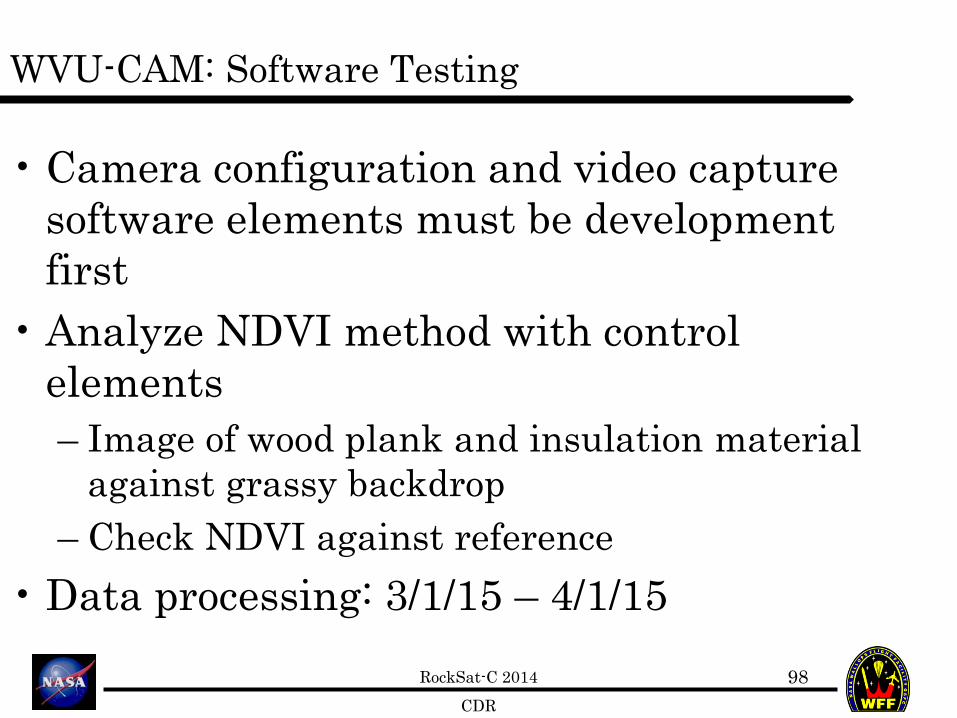
98
• Camera configuration and video capture software elements must be development first
• Analyze NDVI method with control elements – Image of wood plank and insulation material
against grassy backdrop – Check NDVI against reference
• Data processing: 3/1/15 – 4/1/15

RockSat-C 2014 CDR
System Level Design Steven Hard
99

RockSat-C 2014 CDR
Detailed Mass Budget
100
Subsystem Component Total Mass (lbf)PCB 0.1Sensors/DAQ 0.1PCB 0.1Sensors/DAQ 0.05PCB 0.1Sensors/DAQ 0.12PCB 0.1Sensors/DAQ 0.7Sensors 0.3Container 0.2Single Board Computer 0.3Actuators 0.2Batteries 0.4Battery Holders 0.1PCB 0.1Makrolon plates 1.4Standoffs/Mounts 1
105.37
-4.63
WV Rocketeers
TotalOver(+)/Under(-)
SIS
WVU-CAM
PDS
Target Weight (lbf)
RSC 2015 Mass Budget
WVWC-SPACE
WVUTech-SPACE
Marshall-SPACE
Shepherd-SPACE

RockSat-C 2014 CDR
Power Discussion
101
Subsystem Voltage (V) Max Current (A) Time On (min) Watts AhWVWC-SPACE 12.0 0.15 30 1.80 0.08WVU-TECH SPACE 12.0 0.18 30 2.18 0.09Marshall-SPACE 12.0 0.10 30 1.20 0.05Shepherd-SPACE 12.0 0.10 30 1.20 0.05WVU-CAM 12.0 0.35 30 4.20 0.18
Total 0.88 10.58 0.44
Total Power Capacity 4.80
Over (+)/Under (-) 4.36
2.3
WV Rocketeers - RSC2015 Power Budget
# of Flights Margin
12/1/2014

RockSat-C 2014 CDR
Mechanical Model: Isometric Front
102

RockSat-C 2014 CDR
Mechanical Model: Isometric Back
103

RockSat-C 2014 CDR
Risks Steven Hard
104

RockSat-C 2014 CDR
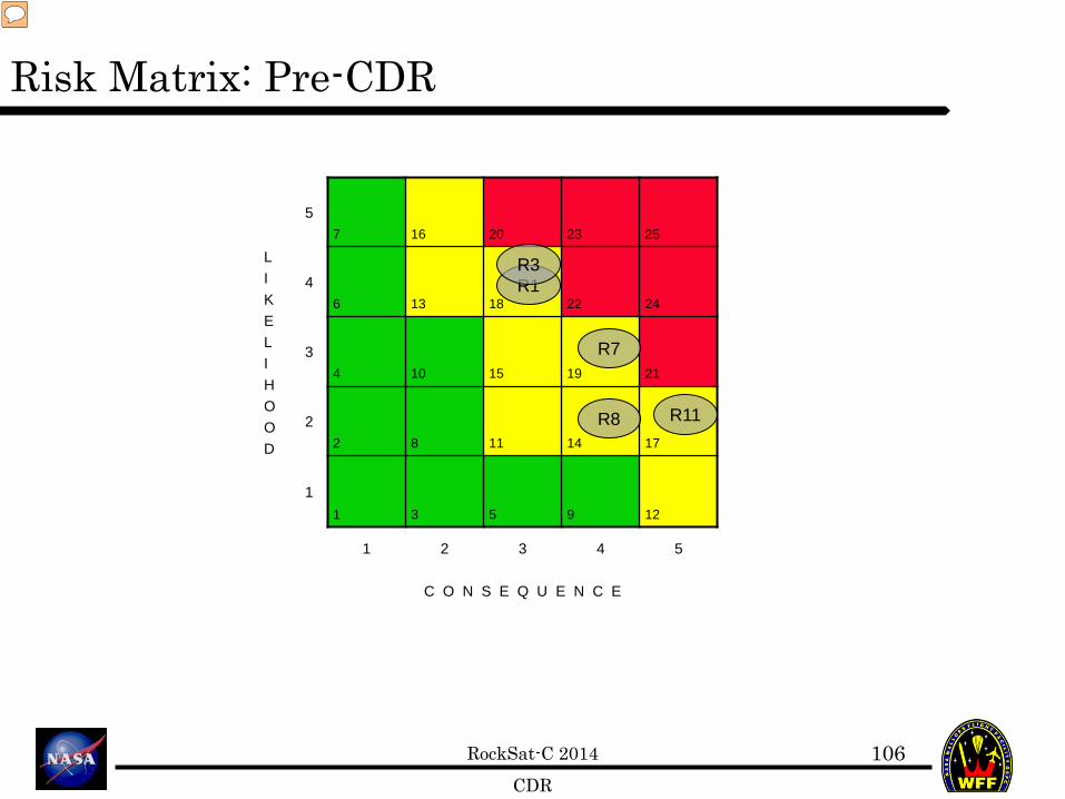
High Risk Items R1: WVWC-SPACE.RSK.1 - The high frequency spinning of the rocket will saturate the gyroscope R3: Marshall-SPACE.RSK.1 - The MightyOhm Geiger kit has not been verified for aerospace applications and could potentially malfunction during flight R7:Shepherd-SPACE.RSK.2 - Mission objectives are not met IF the Razor IMU malfunctions as it is not certain if it is flight worthy so we will no longer have redundancy in FD data when/if it dies R8: WVU-CAM.RSK.1 - Mission objectives are not met IF the linear actuator boom causes damage to the NIR camera lens R11: STR.RSK.2 - Mission objectives are not met IF mounting bracket(s) fails in-flight
RockSat-C 2014 CDR
Risk Matrix: Pre-CDR
106
L I K E L I H O O D
5 7 16 20 23 25
4 6 13 18 22 24
3 4 10 15 19 21
2 2 8 11 14 17
1 1 3 5 9 12
1 2 3 4 5
C O N S E Q U E N C E
R1
R11
R3
R7
R8
Presenter
Presentation Notes
Don’t know about this one, it’s iffy

RockSat-C 2014 CDR
Risk Matrix: Walk-down
107
L I K E L I H O O D
5 7 16 20 23 25
4 6 13 18 22 24
3 4 10 15 19 21
2 2 8 11 14 17
1 1 3 5 9 12
1 2 3 4 5
C O N S E Q U E N C E
R1
R11 R3
R7
R8
• R3: Balloon test • R7: Balloon test • R8: Physical layout • R11: Added camera and structural supports
Presenter
Presentation Notes
Don’t know about this one, it’s iffy

RockSat-C 2014 CDR
User Guide Compliance Steven Hard
108

RockSat-C 2014 CDR
User Guide Compliance
• Mass – 5.37 lb + mass of canister • CG within 1”x1”x1” envelope
– SolidWorks verification to be performed once material properties are specified
– Ballasts will be placed strategically to ensure CG compliance
• Batteries: Rechargeable AA NiMH • RESTATE: T-3min activation type
109

RockSat-C 2014 CDR
Design Overview: Shared Can Logistics
110
• Partners: – West Virginia University Team: WVU-CAM – NASA IV&V/Junior FIRST Lego League: NIR-
CAM Boom – West Virginia Wesleyan College: WVWC-SPACE – Shepherd University: Shepherd-SPACE – Marshall University: Marshall-SPACE – West Virginia University Institute of
Technology: WVUTECH-SPACE – Fairmont State University: Canister Integration

RockSat-C 2014 CDR
Design Overview: Shared Can Logistics
111
• Plan for collaboration – Weekly/Monthly Telecon session – Share designs using Google drive – Will fit check before June
• Mounting to bottom plate and mid plate • Structural interfacing:
– Aluminum standoffs • Ports:
– Optical port – Atmospheric port

RockSat-C 2014 CDR
Project Management Plan Steven Hard
112

RockSat-C 2014 CDR
Schedule
113
• Major Milestones • CDR (12/4/14) • Prototype high risk items (11/28/15) • Flight award announcement (1/16/2015) • Procure remaining components (1/17/2015) • Design PCBs (Week of 2/16/15) • STR (Week of 2/23/15) • High Altitude Balloon Launch (4/4/15) • ISTR (Week of 4/6/15) • Receive canister (Week of 4/20/15) • FMSR (Week of 5/20/15) • Deliver preliminary check-in document (Week of 6/4/15) • LRR (6/17/15) • Travel to Wallops (6/18/15) • Launch (6/25/15)* * Tentative, no guarantee – small chance launch could get cancelled due to weather or other unforeseen delays

RockSat-C 2014 CDR
Budget
114
• Most of experimental components have been procured/delivered • Lead time not anticipated to be a factor
Margin: 0.25 Budget: $3,000.00 Last
Update: 11/17/2014 11:15
Item Supplier Estimated, Specific Cost Number Required Toal Cost Notes
Motor Controller DigiKey $150.00 2 $300.00 1 for testing
Linear Actuator Firgelli $120.00 1 $120.00 1 mini tracked linear actuator
Raspberry Pi DigiKey $35.00 2 $70.00 1 for testing
Pi NoIR Cam Adafruit $25.00 2 $50.00 1 for testing
Mini WebCam Amazon $90.00 2 $180.00 1 for testing
Magnetometer Honeywell $220.00 1 $220.00 Marshall PayloadInertial Measurement Unit (s)
Analog DevicesSparkfun $150.00 2 $300.00 Marshall Payload
Microcontroller DigiKey $25.00 1 $25.00 Marshall Payload
Printed Circuit Boards Advanced Circuits $33.00 4 $132.00 1 board/SPACEMisc. Electronics (R,L,C) DigiKey $50.00 4 $200.00 4 misc/SPACE
Testing Materials Various $75.00 4 $300.00 Testing equipment for each team
$1,897.00
$2,371.25
Total (no margin):
Total (w/ margin):
RockSat-C 2014 CDR
Project Summary
• No critical severity issues currently identified
• Areas of concern – NDVI data processing – NIR camera mount – PCB design
115

RockSat-C 2014 CDR
Team Contact Matrix
116
Team Member Email Address Phone Number US Person? (Y/N)Steven Hard (NASA IV&V - Team Lead) [email protected] 304-367-8287 YDimitris Vassiliadis (WVU - Advisor) [email protected] 304-293-4920 YJosh Waggoner (WVU) [email protected] YGreg Lusk (Fairmont State) [email protected] YFarshid Zabihian (WVU-Tech- Advisor) [email protected] 304-442-3280 YThy Dinh (WVU-Tech - Student Lead) [email protected] YZach Dixon (WVU-Tech) [email protected] YAlex Flores (WVU-Tech) [email protected] YJon Saken (Marshall U - Advisor) [email protected] (304) 696-2753 YSeth Baker (Marshall U - Student Lead) [email protected] YJeremy Chapman (Marshall U) [email protected] YNick Zarilla (Marshall U) [email protected] YCody Porter (Marshall U) [email protected] YPaige Yankey (Marshall U) [email protected] YTracey Delaney (WVWC - Advisor) [email protected] 304-473-8330 YTiffin, Andrew (WVWC - Student Lead) [email protected] YEric Kramer (WVWC) [email protected] YPaul Mallory (WVWC) [email protected] YRalph Wojtowicz (Shepherd U - Advisor) [email protected] 304-876-5783 YRachelle Huff (Shepherd U - Student Lead) [email protected] YAndy Shtanko (Shepherd U) [email protected] Y
• Please re-verify participants US Person Status

RockSat-C 2014 CDR
• Plan of action: – Procure remaining components – Finish prototyping of subsystem
configurations – Finalize PCB designs
• Before break: – Place components order – Norm on electronics software
Conclusion
117