
Creating Spherical Panoramas with the Canon 5D and 15mm ... · Nodal Ninja a lighter and cheaper...
15
Creating Spherical Panoramas with the Canon 5D and 15mm Fisheye Lens Peter Gawthrop Revised 27th September 2007 Contents 1 Introduction 2 2 Projections 2 3 Equipment and Software 4 4 Setting up 4 4.1 Camera ......................................... 4 4.2 Panoramic Head ..................................... 5 5 Taking the Pictures 5 6 Processing 7 6.1 Preprocessing ...................................... 7 6.2 Stitching ......................................... 8 6.3 Composing the image .................................. 12 6.4 GIMP .......................................... 12 6.5 Qtpfsgui ......................................... 13 7 Creating Projections 13 8 Final thoughts on Projections 14 9 Acknowledgement 14 A Exposure blend using ImageMagick 14 B To do list 15 1
Transcript of Creating Spherical Panoramas with the Canon 5D and 15mm ... · Nodal Ninja a lighter and cheaper...
Creating Spherical Panoramaswith the Canon 5D and 15mm Fisheye Lens
Peter Gawthrop
Revised 27th September 2007
Contents
1 Introduction 2
2 Projections 2
3 Equipment and Software 4
4 Setting up 44.1 Camera . . . . . . . . . . . . . . . . . . . . . . . . . . . . . . . . . . . . . . . . . 44.2 Panoramic Head . . . . . . . . . . . . . . . . . . . . . . . . . . . . . . . . . . . . . 5
5 Taking the Pictures 5
6 Processing 76.1 Preprocessing . . . . . . . . . . . . . . . . . . . . . . . . . . . . . . . . . . . . . . 76.2 Stitching . . . . . . . . . . . . . . . . . . . . . . . . . . . . . . . . . . . . . . . . . 86.3 Composing the image . . . . . . . . . . . . . . . . . . . . . . . . . . . . . . . . . . 126.4 GIMP . . . . . . . . . . . . . . . . . . . . . . . . . . . . . . . . . . . . . . . . . . 126.5 Qtpfsgui . . . . . . . . . . . . . . . . . . . . . . . . . . . . . . . . . . . . . . . . . 13
7 Creating Projections 13
8 Final thoughts on Projections 14
9 Acknowledgement 14
A Exposure blend using ImageMagick 14
B To do list 15
1
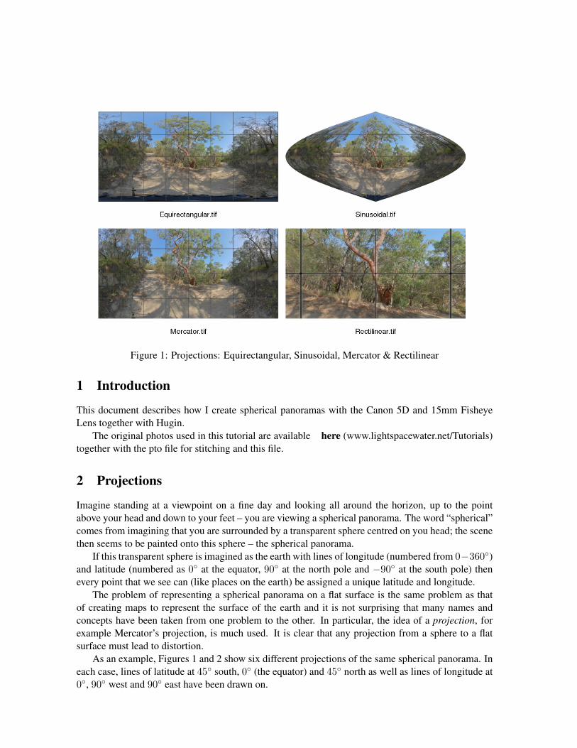
Figure 1: Projections: Equirectangular, Sinusoidal, Mercator & Rectilinear
1 Introduction
This document describes how I create spherical panoramas with the Canon 5D and 15mm FisheyeLens together with Hugin.
The original photos used in this tutorial are available here (www.lightspacewater.net/Tutorials)together with the pto file for stitching and this file.
2 Projections
Imagine standing at a viewpoint on a fine day and looking all around the horizon, up to the pointabove your head and down to your feet – you are viewing a spherical panorama. The word “spherical”comes from imagining that you are surrounded by a transparent sphere centred on you head; the scenethen seems to be painted onto this sphere – the spherical panorama.
If this transparent sphere is imagined as the earth with lines of longitude (numbered from 0−360◦)and latitude (numbered as 0◦ at the equator, 90◦ at the north pole and −90◦ at the south pole) thenevery point that we see can (like places on the earth) be assigned a unique latitude and longitude.
The problem of representing a spherical panorama on a flat surface is the same problem as thatof creating maps to represent the surface of the earth and it is not surprising that many names andconcepts have been taken from one problem to the other. In particular, the idea of a projection, forexample Mercator’s projection, is much used. It is clear that any projection from a sphere to a flatsurface must lead to distortion.
As an example, Figures 1 and 2 show six different projections of the same spherical panorama. Ineach case, lines of latitude at 45◦ south, 0◦ (the equator) and 45◦ north as well as lines of longitude at0◦, 90◦ west and 90◦ east have been drawn on.
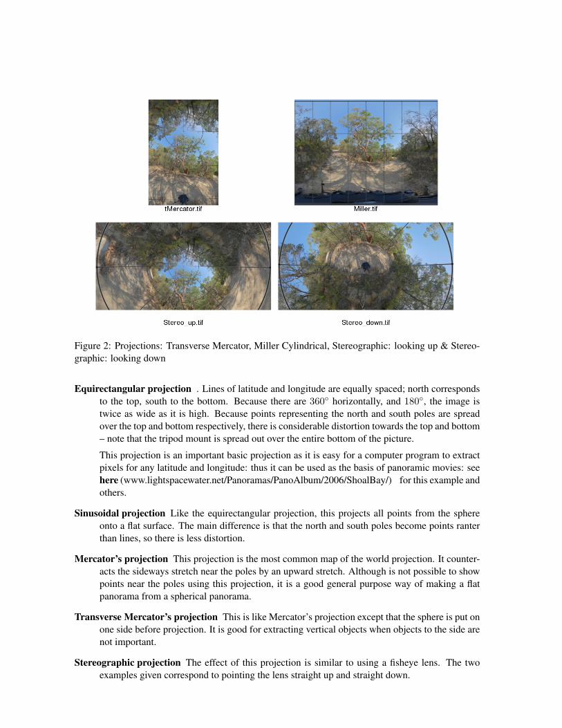
Figure 2: Projections: Transverse Mercator, Miller Cylindrical, Stereographic: looking up & Stereo-graphic: looking down
Equirectangular projection . Lines of latitude and longitude are equally spaced; north correspondsto the top, south to the bottom. Because there are 360◦ horizontally, and 180◦, the image istwice as wide as it is high. Because points representing the north and south poles are spreadover the top and bottom respectively, there is considerable distortion towards the top and bottom– note that the tripod mount is spread out over the entire bottom of the picture.
This projection is an important basic projection as it is easy for a computer program to extractpixels for any latitude and longitude: thus it can be used as the basis of panoramic movies: seehere (www.lightspacewater.net/Panoramas/PanoAlbum/2006/ShoalBay/) for this example andothers.
Sinusoidal projection Like the equirectangular projection, this projects all points from the sphereonto a flat surface. The main difference is that the north and south poles become points ranterthan lines, so there is less distortion.
Mercator’s projection This projection is the most common map of the world projection. It counter-acts the sideways stretch near the poles by an upward stretch. Although is not possible to showpoints near the poles using this projection, it is a good general purpose way of making a flatpanorama from a spherical panorama.
Transverse Mercator’s projection This is like Mercator’s projection except that the sphere is put onone side before projection. It is good for extracting vertical objects when objects to the side arenot important.
Stereographic projection The effect of this projection is similar to using a fisheye lens. The twoexamples given correspond to pointing the lens straight up and straight down.
This article shows how to create and project spherical panoramas using an ordinary digital camerawith a special mount together with some free software.
3 Equipment and Software
Canon EOS 5D a full frame (35mm) digital camera with 12.8 Mpixel resolution.
Canon EF 15mm f/2.8 Fisheye a full-frame fisheye lens.
Canon Remote Switch TC-80N3 to avoid vibration. The cheaper model RS-80N3 would do just aswell.
Panoramic heads There are two alternatives that I use:
Manfrotto 303SPH Virtual Reality Head parallax-free adjustable tripod head with “click” toposition horizontally and adjustable vertical angle. This is an excellent robust device butit is heavy – weighing in at about 2kg.
Nodal Ninja a lighter and cheaper alternative – weighing about 0.5kg. This needs a Manfrotto120 3/8” to 1/4” tripod adaptor to work with the next item.
Manfrotto 438 Ball Camera Leveller to level the panoramic head with needing to adjust tripod legs- built-in level indicator.
Manfrotto 190MF3 Mag Fiber Tripod to hold it all up. Rigid and lightweight.
Lowepro Compu Trekker AW 34030 backpack Carries all the above and a laptop.
Hugin (hugin.sf.net) to stitch the pictures into a panorama.
Gimp (www.gimp.org) for final processing.
4 Setting up
4.1 Camera
In the past, the critical thing here was to have nothing set automatically so that each picture in thepanorama has the same settings. However, The latest release of hugin includes photometric adjust-ment; this means that the camera can be set on Av to automatically choose the shutter speed (variableaperture would cause problems with different lens characteristics at each aperture). It is still worth-while to use auto exposure bracketing (AEB) give over and underexposed panoramas for increaseddynamic range; see section 6. I use jpegs for simplicity and reduced space; this gives plenty of rangedue to three exposures. But use raw if you wish.
1. Set the camera mode dial to Av (fixed aperture).
2. Use the menu to set AEB (auto exposure bracketing). Set to the maximum of 2 stops.
3. Set ISO to 200 (good value for UK, use 100 for Australia).
4. Set white balance to “daylight”.

5. Set aperture to 16 – this gives a good depth of field.
6. Use the menu to set the highest quality jpeg.
7. Use to menu to “Save camera settings” – you can now use the C mode on the dial whenever youtake a panorama.
8. Set the lens to MF (manual focus).
9. The 5D has a useful “select folder” feature. Use the menu to create a new folder each time youtake a panorama.
4.2 Panoramic Head
The critical thing here is to set up the head once and for all such that the camera rotates about thenodal point to give no parallax.
1. Fix the “Ball Camera Leveller” to the tripod – it can be left there permanently.
2. Fix the “Virtual Reality Head” to the “Ball Camera Leveller”. Tighten at least one screw so thatit can’t move.
3. Use the “Ball Camera Leveller” to level the “Virtual Reality Head”.
4. Follow the Manfrotto or Nodal Ninja instructions to set up the “Virtual Reality Head” . Accu-racy is important.
5. Stick coloured insulation tape to each plate to mark positions; this saves later recalibration.
6. Select the “n=8” (45 degrees) rotation angle.
7. Remove the camera plate from the head, but leave attached to the camera.
8. Remove the head from the leveller - it will fit in the backpack without folding or disassemblywhen the vertical rotation is set to appropriately.
5 Taking the Pictures
It is possible to cover the panoramic sphere with 8 pictures. I don’t like using zenith and nadir shots asthey are difficult to stitch; I find the 4+4 pattern described below works well. The top row of picturesare 30degrees up at 0,90,180,270; the bottom row are 30 degrees down at -45,45,135,225. A diagramis given in Figure 3; Figure 4 gives an example set of images.
Because spherical panoramas must include features in direct sunlight and shadow as well as thesky, it is not possible to get a satisfactory exposure to cover the sphere. I use the auto exposurebracketing (see section 4.1) feature to give me three exposures; this does give a satisfactory rangewhen the three exposures are combined (see section 6). Figure 5 is an over exposed version of Figure4; Figure 6 is an under exposed version of Figure 4.
1. Choose a location for the tripod. Consider:
(a) Artistic merit

Figure 3: Camera orientation. The firm lines show the four directions at 30deg up, the dashed lines at30deg down. The numbers show the order in which the images are taken
(b) Firm footing for the tripod
(c) Safety – you must be able to walk around the tripod whilst concentrating on the camera.
(d) Hiding the sun – ie the camera is in shadow.
2. Fix the panoramic head and the camera. Make sure the camera plate is exactly located to thetape marks.
3. Attach the remote switch to the camera.
4. Level using the “Ball Camera Leveller”.
5. Set the camera mode dial to C (see section 4.1).
6. Make sure the lens is set to MF (manual focus) and focus it to infinity.
7. Set the camera pointing up at 30 degrees to the horizontal. Set the horizontal position at theabout zero and pointing towards the central feature of your panorama.
8. Use the remote to take the three bracketed exposures and rotate the camera though 90 degreeshorizontally (2 clicks).
9. Repeat to give three further sets of pictures.
10. You now have the top row of each of Figures 4– 6 (0.jpg–03.jpg).
11. Set the camera pointing down at 30 degrees to the horizontal.
12. Set the horizontal position back by 45 degrees (1 click back). Repeat steps 8 and 9.
13. You now have the bottom row of each of Figures 4– 6(04.jpg–07.jpg).
14. The 24 pictures should now be in their own folder. Use item 9 of section 4.1 to create a newfolder for the next panorama.
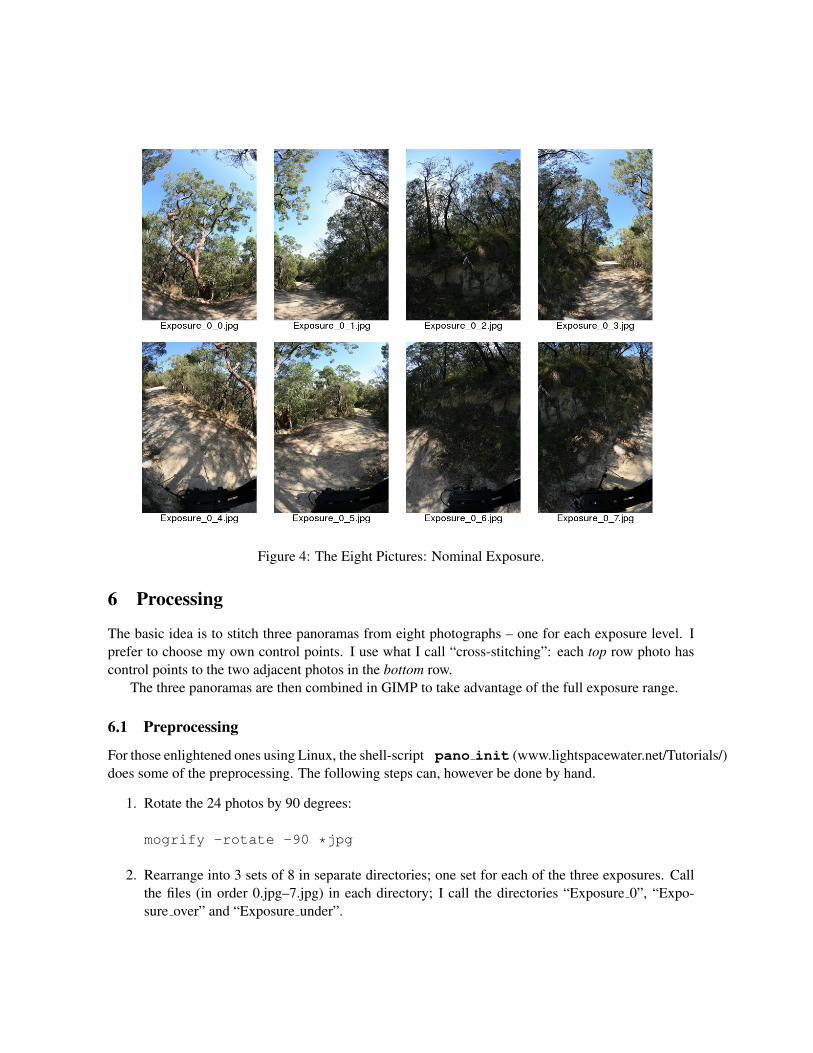
Figure 4: The Eight Pictures: Nominal Exposure.
6 Processing
The basic idea is to stitch three panoramas from eight photographs – one for each exposure level. Iprefer to choose my own control points. I use what I call “cross-stitching”: each top row photo hascontrol points to the two adjacent photos in the bottom row.
The three panoramas are then combined in GIMP to take advantage of the full exposure range.
6.1 Preprocessing
For those enlightened ones using Linux, the shell-script pano init (www.lightspacewater.net/Tutorials/)does some of the preprocessing. The following steps can, however be done by hand.
1. Rotate the 24 photos by 90 degrees:
mogrify -rotate -90 *jpg
2. Rearrange into 3 sets of 8 in separate directories; one set for each of the three exposures. Callthe files (in order 0.jpg–7.jpg) in each directory; I call the directories “Exposure 0”, “Expo-sure over” and “Exposure under”.
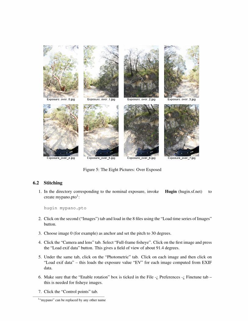
Figure 5: The Eight Pictures: Over Exposed
6.2 Stitching
1. In the directory corresponding to the nominal exposure, invoke Hugin (hugin.sf.net) tocreate mypano.pto1:
hugin mypano.pto
2. Click on the second (“Images”) tab and load in the 8 files using the “Load time series of Images”button.
3. Choose image 0 (for example) as anchor and set the pitch to 30 degrees.
4. Click the “Camera and lens” tab. Select “Full-frame fisheye”. Click on the first image and pressthe “Load exif data” button. This gives a field of view of about 91.4 degrees.
5. Under the same tab, click on the “Photometric” tab. Click on each image and then click on“Load exif data” – this loads the exposure value “EV” for each image computed from EXIFdata.
6. Make sure that the “Enable rotation” box is ticked in the File -¿ Preferences -¿ Finetune tab –this is needed for fisheye images.
7. Click the “Control points” tab.1“mypano” can be replaced by any other name
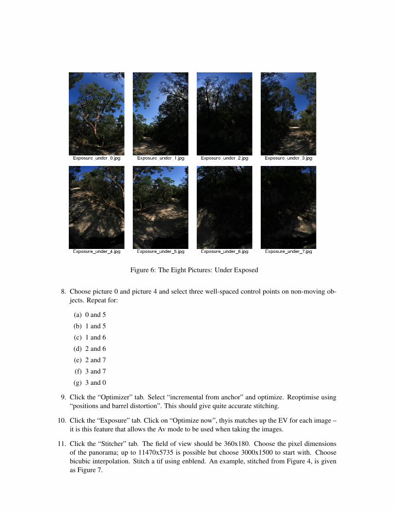
Figure 6: The Eight Pictures: Under Exposed
8. Choose picture 0 and picture 4 and select three well-spaced control points on non-moving ob-jects. Repeat for:
(a) 0 and 5
(b) 1 and 5
(c) 1 and 6
(d) 2 and 6
(e) 2 and 7
(f) 3 and 7
(g) 3 and 0
9. Click the “Optimizer” tab. Select “incremental from anchor” and optimize. Reoptimise using“positions and barrel distortion”. This should give quite accurate stitching.
10. Click the “Exposure” tab. Click on “Optimize now”, thyis matches up the EV for each image –it is this feature that allows the Av mode to be used when taking the images.
11. Click the “Stitcher” tab. The field of view should be 360x180. Choose the pixel dimensionsof the panorama; up to 11470x5735 is possible but choose 3000x1500 to start with. Choosebicubic interpolation. Stitch a tif using enblend. An example, stitched from Figure 4, is givenas Figure 7.
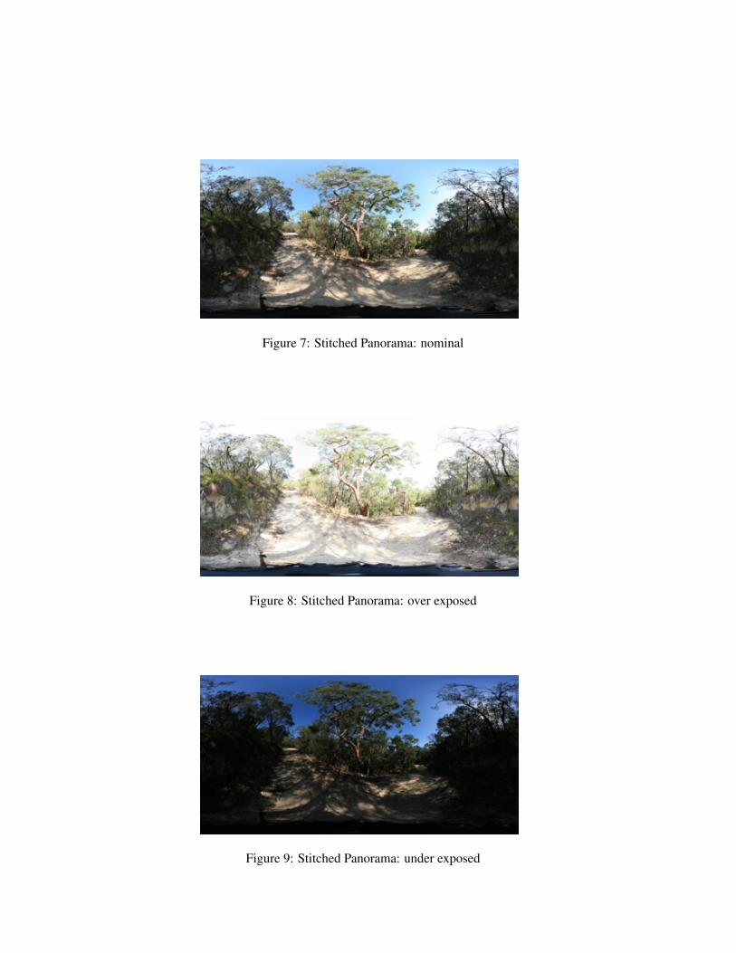
Figure 7: Stitched Panorama: nominal
Figure 8: Stitched Panorama: over exposed
Figure 9: Stitched Panorama: under exposed
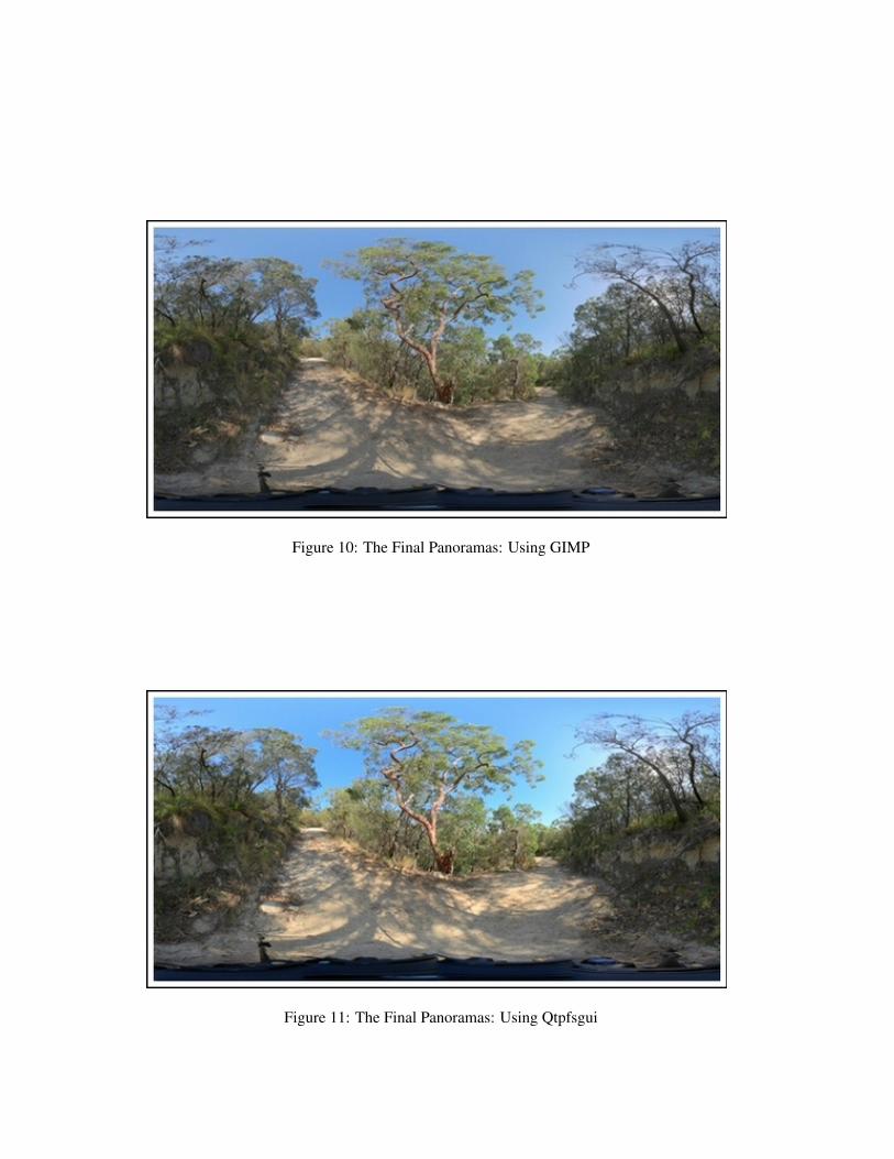
Figure 10: The Final Panoramas: Using GIMP
Figure 11: The Final Panoramas: Using Qtpfsgui

12. Copy (or symlink) the pto file to the two other directories and stitch the under and over exposedpanoramas; the control points etc will be the same! An example, stitched from Figure 5, isgiven as Figure 8, and an example, stitched from Figure 6, is given as Figure 9.
6.3 Composing the image
There are at least three possible approaches:
1. Load the three panoramas into Gimp (www.gimp.org) as separate layers and use layermasks to combine.
2. Load the three panoramas into Cinepaint (www.cinepaint.org) using File-¿New from¿HDRBracketing. To create a 32bit floating point image.
3. Use qtpfsgui (qtpfsgui.sf.net) to create a High Dynamic Range (HDR) image from the threepanoramas and tonemap the result to give a Low Dynamic Range image such as a jpeg.
I have had good results from the first and the third approaches; I prefer the third.
6.4 GIMP
1. Invoke Gimp with the correctly exposed panorama:
gimp Exposure_0/mypano.tif
2. Use the right mouse button to bring up the menu File-¿Open as Layer and load Exposure under/mypano.tif.
3. Right click on the thumbnail for this new layer to bring up Add layer mask. Choose the“Grayscale copy of layer” option.
4. Repeat 2 and 3 with Exposure over/mypano.tif except that the “Invert Mask” box is ticked inthe mask menu.
5. You should now have a reasonable combined image with detail in the shadows and no overex-posed sections. See Figure 10 as an example.
6. The top two layers can be adjusted by:
(a) adjusting layer opacity,
(b) adjusting the contrast of each layer mask and
(c) painting on the layer mask.
7. Save the final version as a jpeg.
This process (with much more sophistication) is implemented in theexposure-blend ( turtle.as.arizona.edu/jdsmith/exposure blend.php) plugin – this is strongly recom-mended.
An alternative suitable for batch implementation is given in Appendix A.
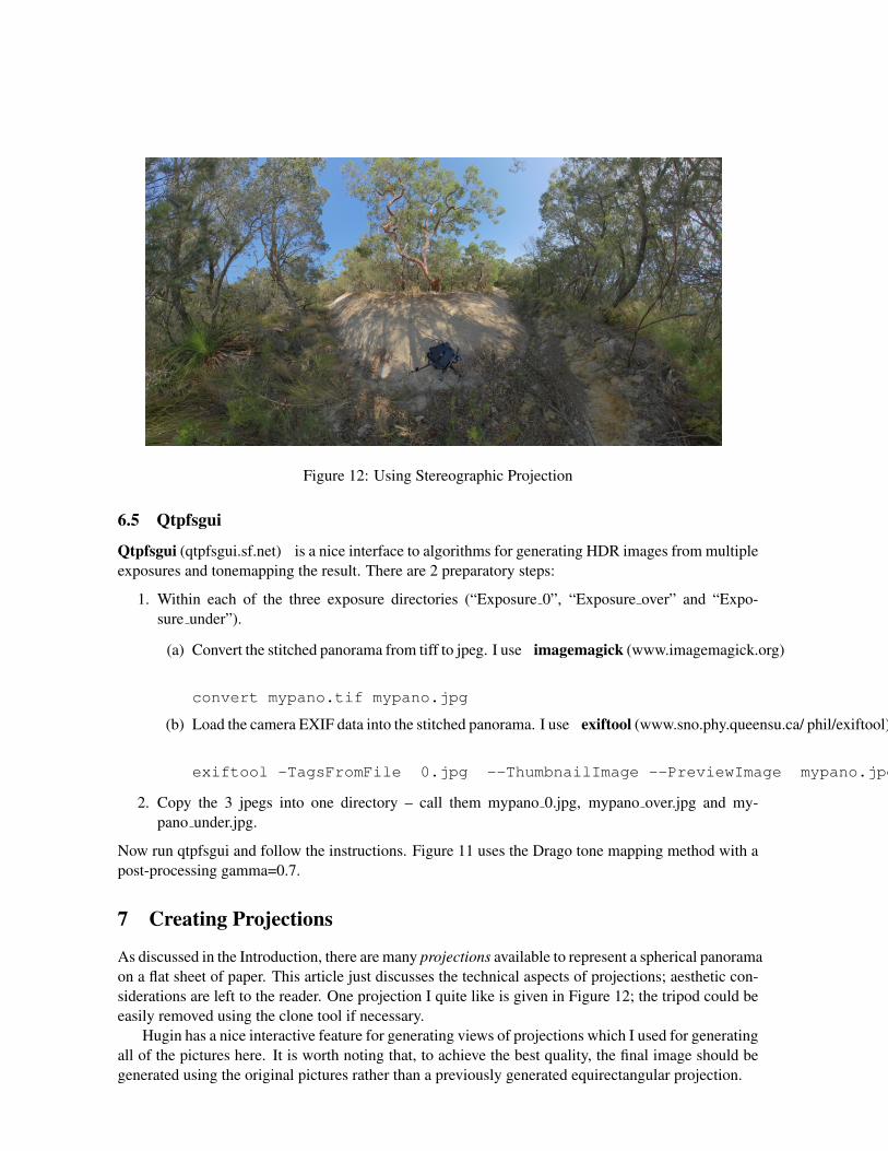
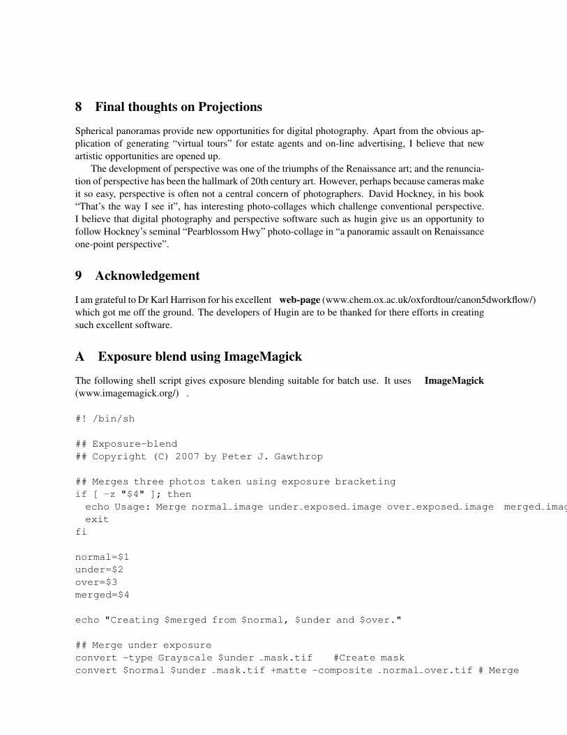
Figure 12: Using Stereographic Projection
6.5 Qtpfsgui
Qtpfsgui (qtpfsgui.sf.net) is a nice interface to algorithms for generating HDR images from multipleexposures and tonemapping the result. There are 2 preparatory steps:
1. Within each of the three exposure directories (“Exposure 0”, “Exposure over” and “Expo-sure under”).
(a) Convert the stitched panorama from tiff to jpeg. I use imagemagick (www.imagemagick.org)
convert mypano.tif mypano.jpg
(b) Load the camera EXIF data into the stitched panorama. I use exiftool (www.sno.phy.queensu.ca/ phil/exiftool)
exiftool -TagsFromFile 0.jpg --ThumbnailImage --PreviewImage mypano.jpg
2. Copy the 3 jpegs into one directory – call them mypano 0.jpg, mypano over.jpg and my-pano under.jpg.
Now run qtpfsgui and follow the instructions. Figure 11 uses the Drago tone mapping method with apost-processing gamma=0.7.
7 Creating Projections
As discussed in the Introduction, there are many projections available to represent a spherical panoramaon a flat sheet of paper. This article just discusses the technical aspects of projections; aesthetic con-siderations are left to the reader. One projection I quite like is given in Figure 12; the tripod could beeasily removed using the clone tool if necessary.
Hugin has a nice interactive feature for generating views of projections which I used for generatingall of the pictures here. It is worth noting that, to achieve the best quality, the final image should begenerated using the original pictures rather than a previously generated equirectangular projection.
8 Final thoughts on Projections
Spherical panoramas provide new opportunities for digital photography. Apart from the obvious ap-plication of generating “virtual tours” for estate agents and on-line advertising, I believe that newartistic opportunities are opened up.
The development of perspective was one of the triumphs of the Renaissance art; and the renuncia-tion of perspective has been the hallmark of 20th century art. However, perhaps because cameras makeit so easy, perspective is often not a central concern of photographers. David Hockney, in his book“That’s the way I see it”, has interesting photo-collages which challenge conventional perspective.I believe that digital photography and perspective software such as hugin give us an opportunity tofollow Hockney’s seminal “Pearblossom Hwy” photo-collage in “a panoramic assault on Renaissanceone-point perspective”.
9 Acknowledgement
I am grateful to Dr Karl Harrison for his excellent web-page (www.chem.ox.ac.uk/oxfordtour/canon5dworkflow/)which got me off the ground. The developers of Hugin are to be thanked for there efforts in creatingsuch excellent software.
A Exposure blend using ImageMagick
The following shell script gives exposure blending suitable for batch use. It uses ImageMagick(www.imagemagick.org/) .
#! /bin/sh
## Exposure-blend## Copyright (C) 2007 by Peter J. Gawthrop
## Merges three photos taken using exposure bracketingif [ -z "$4" ]; thenecho Usage: Merge normal image under exposed image over exposed image merged imageexit
fi
normal=$1under=$2over=$3merged=$4
echo "Creating $merged from $normal, $under and $over."
## Merge under exposureconvert -type Grayscale $under mask.tif #Create maskconvert $normal $under mask.tif +matte -composite normal over.tif # Merge

## Merge over exposureconvert -negate -type Grayscale $over mask.tif #Create maskconvert normal over.tif $over mask.tif +matte -composite $merged # Merge
## Cleanrm -f mask.tif under masked.tif normal over.tif
B To do list
There are more things I would like to do but haven’t yet.
1. Remove chromatic aberration from the original images there is a hugin tutorial hugin tutorial(hugin.sourceforge.net/tutorials/tca/) .
2. Align the each set of three images – there can be a pixel or two error. One approach is to usealign image stack (qtpfsgui.wiki.sourceforge.net/align image stack) .
3. Use HDR throughout – see HDR workflow with hugin (wiki.panotools.org/HDR workflow with hugin).