Creating Multiprocessor Nios II Systems Tutorialmbolic/ceg4131/tt_nios2_multiprocessor... ·...
50
Creating Multiprocessor Nios II Systems Tutorial 101 Innovation Drive San Jose, CA 95134 (408) 544-7000 http://www.altera.com TU-N2033005-1.0
-
Upload
phungxuyen -
Category
Documents
-
view
232 -
download
3
Transcript of Creating Multiprocessor Nios II Systems Tutorialmbolic/ceg4131/tt_nios2_multiprocessor... ·...

Creating Multiprocessor Nios II Systems Tutorial
101 Innovation Drive San Jose, CA 95134 (408) 544-7000 http://www.altera.com
TU-N2033005-1.0

Copyright © 2005 Altera Corporation. All rights reserved. Altera, The Programmable Solutions Company, the stylized Altera logo, specific device des-ignations, and all other words and logos that are identified as trademarks and/or service marks are, unless noted o therwise, the trademarks andservice marks o f Altera Corporation in the U.S . and other countries. All other product or service names are the property of their respective ho lders. Al-tera products are protected under numerous U.S. and foreign patents and pending applications, maskwork rights, and copyrights. Altera warrantsperformance of its semiconductor products to current specifications in accordance with Altera's standard warranty, but reserves the right to makechanges to any products and services at any time without notice. Altera assumes no responsibility or liability ar ising out of the ap-plication or use of any information, product, or service descr ibed herein ex cept as expressly agreed to in writing by AlteraCorporation. Altera customers are advised to obtain the latest version of device specifications before relying on any published in-formation and before placing orders for products or services.
ii Altera Corporation

Altera Corporation iii May 2005
Contents
About This Tutorial ........................................................... ix How to Find Information....................................................................................v How to Contact Altera ........................................................................................vi Typographical Conventions...............................................................................vii
Designing Mutliprocessor Systems ........................................9 Introduction .......................................................................................................... 9 Assumptions about the Reader.......................................................................... Error! Bookmark not defined. Benefits of Multiprocessor Systems ..................................................................10 Nios II Multiprocessor Systems.........................................................................10 Hardware Design Considerations.....................................................................11
Autonomous Multiprocessors ...................................................................11 Multiprocessors that Share Resources......................................................12
Sharing Resources in a Multiprocessor System ..............................................12 Sharing Memory...........................................................................................14 The Hardware Mutex Core ........................................................................15 Nios II Systems Without a Mutex Core....................................................16 Sharing Peripherals Between Multiple Processors.................................16 Multiprocessors & Overlapping Address Space ....................................17
Software Design Considerations .......................................................................19 Program Memory.........................................................................................19 Boot Addresses.............................................................................................23 Running & Debugging Multiprocessor Systems from the Nios II IDE.........................................................................................................................25
Building & Running Software on a Nios II Multiprocessor .............30 Introduction ..........................................................................................................27 Hardware and Software Requirements............................................................27 Creating the Hardware System .........................................................................28
Getting Started with a Standard Example Design..................................28 Adding a Second Processor........................................................................30 Adding a Third Processor...........................................................................30
Adding a Timer for cpu2 ....................................................................................31 Adding a Timer for cpu3 ............................................................................32 Adding a Hardware Mutex........................................................................32 Adding a Message Buffer Memory...........................................................33 Connecting Shared Resources....................................................................33 Setting Reset and Exception Addresses ...................................................35
Setting Reset and Exception Addresses for cpu1 ...........................35 Setting Reset and Exception Addresses for cpu2 ...........................35 Setting Reset and Exception Addresses for cpu3 ...........................36

Generating and Compiling the System ....................................................36 Creating Software for the Multiprocessor System .........................................37
Starting the Nios II IDE...............................................................................37 Creating a Software Project for cpu1 ........................................................38 Creating a Software Project for cpu2 ........................................................41 Creating a Software Project for cpu3 ........................................................42 Building the Software Projects...................................................................43 Setting up the Nios II IDE for Multiprocessor Debug ...........................43 Creating a Debug Configuration for Each Processor.............................44 Creating a Multiprocessor Collection.......................................................46 Starting the Multiprocessor Collection.....................................................47 Debugging the Software Projects on the Board ......................................47
iv Altera Corporation Nios II Multiprocessor Tutorial May 2005

Altera Corporation v May 2005
About This Tutorial
This tutorial describes the features of the Nios II processor and SOPC Builder tool used for creating systems with two or more processors that work together to share common resources and with an example, guides you through the steps of creating a multiprocessor system.
The following table shows the revision history of this document.
Date Description
April 2005 First publication.
How to Find Information
The Adobe Acrobat Find feature allows you to search the contents of a PDF file. Click the binoculars toolbar icon to open the Find dialog box.
Bookmarks serve as an additional table of contents. Thumbnail icons, which provide miniature previews of each page,
provide a link to the pages. Numerous links, shown in green text, allow you to jump to related
information.

How to Contact Altera
vi Altera Corporation Nios II Multiprocessor Tutorial May 2005
How to Contact Altera
For the most up-to-date information about Altera products, go to the Altera world-wide web site at www.altera.com. For technical support on this product, go to www.altera.com/mysupport. For additional information about Altera products, consult the sources shown below.
Information Type USA & Canada All Other Locations
www.altera.com/mysupport/ altera.com/mysupport/ Technical support
(800) 800-EPLD (3753)
(7:00 a.m. to 5:00 p.m. Pacific Time)
+1 408-544-7000
(7:00 a.m. to 5:00 p.m. (GMT -8:00) Pacific Time
Product literature
www.altera.com www.altera.com
Altera literature services
[email protected] [email protected]
Non-technical customer service
(800) 767-3753 +1 408-544-7000
(7:30 a.m. to 5:30 p.m. (GMT -8:00) Pacific Time
FTP site ftp.altera.com ftp.altera.com

Nios II Multiprocessor Tutorial
Altera Corporation vii May 2005 Nios II Multiprocessor Tutorial
Typographical Conventions
This document uses the typographical conventions shown below.
Visual Cue Meaning Bold Type with Initial Capital Letters
Command names, dialog box titles, checkbox options, and dialog box options are shown in bold, initial capital letters. Example: Save As dialog box.
bold type External timing parameters, directory names, project names, disk drive names, filenames, filename extensions, and software utility names are shown in bold type. Examples: fMAX, \qdesigns directory, d: drive, chiptrip.gdf file.
Italic Type with Initial Capital Letters
Document titles are shown in italic type with initial capital letters. Example: AN 75: High-Speed Board Design.
Italic type Internal timing parameters and variables are shown in italic type. Examples: tPIA, n + 1. Variable names are enclosed in angle brackets (< >) and shown in italic type. Example: <file name>, <project name>.pof file.
Initial Capital Letters Keyboard keys and menu names are shown with initial capital letters. Examples: Delete key, the Options menu.
“Subheading Title” References to sections within a document and titles of on-line help topics are shown in quotation marks. Example: “Typographic Conventions.”
Courier type Signal and port names are shown in lowercase Courier type. Examples: data1, tdi, input. Active-low signals are denoted by suffix n, e.g., resetn. Anything that must be typed exactly as it appears is shown in Courier type. For example: c:\qdesigns\tutorial\chiptrip.gdf. Also, sections of an actual file, such as a Report File, references to parts of files (e.g., the AHDL keyword SUBDESIGN), as well as logic function names (e.g., TRI) are shown in Courier.
1., 2., 3., and a., b., c., etc.
Numbered steps are used in a list of items when the sequence of the items is important, such as the steps listed in a procedure.
• Bullets are used in a list of items when the sequence of the items is not important.
v The checkmark indicates a procedure that consists of one step only.

Typographical Conventions
viii Altera Corporation Nios II Multiprocessor Tutorial May 2005
Visual Cue Meaning
1 The hand points to information that requires special attention.
c The caution indicates required information that needs special consideration and understanding and should be read prior to starting or continuing with the procedure or process.
w The warning indicates information that should be read prior to starting or continuing the procedure or processes.
r The angled arrow indicates you should press the Enter key.
f The feet direct you to more information on a particular topic.

Altera Corporation 9 May 2005
Designing Multiprocessor Systems
Introduction
Any system which incorporates two or more microprocessors working together to perform a task is commonly referred to as a multiprocessor system. Developers using Altera’s Nios II processor and SOPC Builder tool can design and build multiprocessor systems that share resources quickly. SOPC Builder is a system development tool for creating SOPC design systems based on processors, peripherals, and memories. A Nios II processor system refers to a system with a processor core, a set of on-chip peripherals, on-chip memory and interfaces to off-chip memory all implemented on a single Altera device.
In this document, the Designing Multiprocessor Systems chapter describes the features of the Nios II processor and SOPC Builder tool that are useful for creating systems with two or more processors. The Building & Running Software on a Nios II Multiprocessor System chapter guides you through a step-by step process for building a multiprocessor system containing three processors that all share a memory buffer. Using the Nios II IDE, you will create and debug three software projects, one for each processor in the system.
After completing this document, you will have the knowledge to perform the following:
Build an SOPC Builder system containing more than one Nios II processor.
Safely share resources between processors avoiding data corruption.
Build software projects for multiprocessor systems using Nios II IDE
Debug multiple software projects running on multiple processors using Nios II IDE.
This chapter assumes that you are familiar reading and writing embedded software and that you have read and followed the step-by-step procedures for building a microprocessor system in the Nios II Hardware Development Tutorial. This tutorial can be found on the Nios II Processor Literature page at http://www.altera.com/literature/lit-nio2.jsp.

Benefits of Multiprocessor Systems
Benefits of Multiprocessor Systems
Multiprocessor systems possess the benefit of increased performance, but nearly always at the price of significantly increased system complexity. For this reason, the use of multiprocessor systems has historically been limited to workstation and high-end PC computing using a complex method of load-sharing often referred to as symmetric multi processing (SMP). While the overhead of SMP is typically too high for most embedded systems, the idea of using multiple processors to perform different tasks and functions on different processors in embedded applications (asymmetrical) is showing increased interest. Altera FPGAs provide an ideal platform for developing asymmetric embedded multiprocessor systems since the hardware can easily be modified and tuned using the SOPC Builder tool to provide optimal system performance. Furthermore, with a powerful integration tool like SOPC Builder, different system configurations can be designed, built, and evaluated very quickly.
Nios II Multiprocessor Systems
Nios II version 5.0 and higher includes features to help with the creation and debugging of multiprocessor systems. Multiple Nios II processors are able to efficiently share system resources thanks to the multimaster friendly slave-side arbitration capabilities of the Avalon bus fabric. Since the capabilities of SOPC Builder now allow users to almost effortlessly add as many processors to a system as desired, the design challenge of building multiprocessor systems no longer lies in the arranging and connecting of hardware components. The design challenge in building multiprocessor systems now lies in writing the software for those processors so they operate efficiently together, and do not conflict with one another.
To aid in the prevention of multiple processors interfering with each other, a hardware mutex core is included in the Nios II Development Kits. The hardware mutex core allows different processors to claim ownership of a shared resource for a period of time. This temporary ownership of a resource by a processor prevents the shared resource from becoming corrupted by the actions of another processor. To learn more about the hardware mutex core, see the Mutex Core with Avalon Interface in the Nios II Processor Reference Handbook.
Performing software debug on multiprocessor systems is made easier with the Nios II IDE, allowing users to launch and stop
10 Altera Corporation Nios II Multiprocessor Tutorial May 2005

Nios II Multiprocessor Tutorial
software debug sessions on different processors with a single operation.
Hardware Design Considerations
Nios II multiprocessor systems are split into two main categories, those that share resources, and those in which each processor is autonomous and does not share resources with other processors.
Autonomous Multiprocessors
While autonomous multiprocessor systems contain multiple processors, these processors are completely autonomous and do not communicate with the others, much as if they were completely separate systems. Systems of this type are typically less complicated and pose fewer challenges since by design, the system’s processors are incapable of interfering with each other’s operation. Figure 1 shows a block diagram of two autonomous processors in a multiprocessor system.
Figure 1: Autonomous Multiprocessor System
Processor 1
Processor 2
Memory 1
UART 1
Timer 1
Memory 2
UART 2
Timer 2
Altera Corporation 11 May 2005 Nios II Multiprocessor Tutorial
Sharing Resources in a Multiprocessor System
Multiprocessors that Share Resources
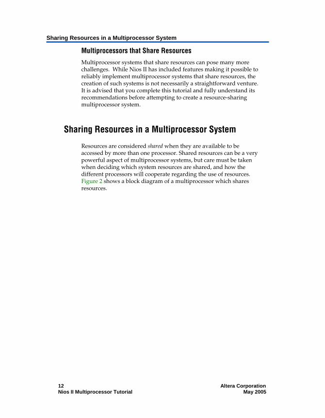
Multiprocessor systems that share resources can pose many more challenges. While Nios II has included features making it possible to reliably implement multiprocessor systems that share resources, the creation of such systems is not necessarily a straightforward venture. It is advised that you complete this tutorial and fully understand its recommendations before attempting to create a resource-sharing multiprocessor system.
Sharing Resources in a Multiprocessor System
Resources are considered shared when they are available to be accessed by more than one processor. Shared resources can be a very powerful aspect of multiprocessor systems, but care must be taken when deciding which system resources are shared, and how the different processors will cooperate regarding the use of resources. Figure 2 shows a block diagram of a multiprocessor which shares resources.
12 Altera Corporation Nios II Multiprocessor Tutorial May 2005

Nios II Multiprocessor Tutorial
Figure 2: Multiprocessor System with Shared Resource
Processor 1
Processor 2
Memory 1
UART 1
Timer 1
Memory 2
Timer 2
SharedMemory
Resources can be made shareable by simply connecting them to multiple processor bus masters in the connection matrix of SOPC Builder, but that in no way guarantees that the processors that share them will do so non-destructively. The software running on each processor is responsible for coordinating access to shared resources with the system’s other processors. Figure 3 shows a multiprocessor system in which two processors share an on-chip memory. The on-chip memory is considered shared because the data master ports of both processors are connected to the same slave port of the memory. Since cpu1 and cpu2 are both physically capable of writing blocks of data to the shared memory at the same time, the software for those processors must be written carefully to protect the integrity of the data stored in the shared memory.
Altera Corporation 13 May 2005 Nios II Multiprocessor Tutorial

Sharing Resources in a Multiprocessor System
Figure 3: Multiprocessor System Sharing On-Chip Memory
Sharing Memory
The most common type of shared resource in multiprocessor systems is memory. Shared memory can be used for anything from a simple flag whose purpose is to communicate status between processors, to complex data structures that are collectively computed by many processors simultaneously.
If a memory component is to contain the program memory for more than one processor, each processor sharing the memory is required to use a separate area for code execution. The processors cannot share the same area of memory for program space. Each processor must have its own unique .text, .rodata, .rwdata, heap, and stack sections. See Software Design Considerations for information on how to make sure each processor sharing a memory component for program space uses a dedicated area within that memory.
If a memory component is to be shared for data purposes, its slave port needs to be connected to the data masters of the processors that are sharing the memory. Sharing data memory between multiple processors can be trickier than sharing instruction memory due to the fact that data memory can be written to as well as read. If one processor is writing to a particular area of shared data memory at the
14 Altera Corporation Nios II Multiprocessor Tutorial May 2005

Nios II Multiprocessor Tutorial
same time another processor is reading or writing to that area, data corruption will likely occur, causing application errors at the very least, and possibly a system crash.
The processors sharing memory need a mechanism to inform one another when they are using a shared resource, so the other processors do not interfere.
The Hardware Mutex Core
The Nios II processor allows the handling of protection of shared resources with its hardware mutex core feature. This hardware mutex core is not an internal feature of the Nios II processor, but a small SOPC Builder component named Mutex.
The term mutex stands for “mutual exclusion“, and a mutex does exactly as its name suggests. A mutex allows cooperating processors to agree that one of them should be allowed mutually exclusive access to a hardware resource in the system. This is useful for the purpose of protecting resources from data corruption that can occur if more than one processor attempts to use the resource at the same time.
The mutex core acts as a shared resource, providing an atomic “test and set” operation in which a processor may test if the mutex is available and if so, acquire it in a single operation. When the processor is finished using the shared resource associated with the mutex, the processor releases the mutex. At this point, another processor may acquire the mutex and use the shared resource. Without the mutex, this kind of function would normally require two separate “test” and “set” instructions between which, another processor could also test for availability and succeed. This situation would leave two processors both thinking they successfully acquired mutually exclusive access to the shared resource when clearly they did not.
It is important to note that the mutex core does not physically protect resources in the system from being accessed at the same time by multiple processors. The software running on the processors is responsible for abiding by the rules. The software must be designed to always acquire the mutex before accessing its associated shared resource.
Another kind of mutex, called a software mutex is common in many operating systems for providing the same protection of resources. The difference is that a software mutex is purely a software construct that is used to protect hardware resources from being corrupted by
Altera Corporation 15 May 2005 Nios II Multiprocessor Tutorial

Sharing Resources in a Multiprocessor System
multiple processes running on the same processor. A hardware mutex core is an SOPC Builder component with an Avalon interface that uses logic to guarantee only one processor is granted lock of the mutex at any given time. This means that as long as every processor waits until it locks the mutex before using the associated shared resource, the resource will be protected from corruption due to simultaneous access by multiple processors. Each processor must first request a lock of the mutex core before accessing the associated shared resource.
Nios II Systems Without a Mutex Core
In most cases, a mutex core should be used to protect any resource shared between multiple processors. However, there are some limited cases when a mutex core may not be necessary. Such cases might include one way or circular message buffer arrangements where only one processor ever writes to a particular set of memory locations. However, sharing resources safely without a mutex core can be complicated. When in doubt, using the mutex core is highly recommended.
Sharing Peripherals Between Multiple Processors
In general, with the exception of the mutex core, Nios II does not support the sharing of non-memory peripherals between multiple processors.
Sharing peripherals in multiprocessor systems presents some difficult challenges, and is generally considered to be inefficient system design. The biggest problems arise for peripherals with interrupts. If a peripheral is allowed to interrupt all the processors which share it, there is no reliable way to guarantee which processor will respond first and service that interrupt. Additionally, if the peripheral is used as an input device for multiple processors, it becomes difficult to determine which processor is supposed to collect given input from the device. While it is conceivable that a complex system of handshaking could be created to handle these scenarios, it is beyond the scope of this document, and is unsupported by the Nios II HAL library. For more information on the Nios II HAL Library, see the Nios II Software Developer’s Handbook.
Altera recommends that each non-memory peripheral be accessible by only one processor in the system. If other processors require use of the peripheral, they should use a message buffer that is either mutex-protected or otherwise multiprocessor safe when communicating with the processor that is connected to that peripheral.
16 Altera Corporation Nios II Multiprocessor Tutorial May 2005

Nios II Multiprocessor Tutorial
When building any system, especially a multiprocessor system, it is advisable to only make connections between peripherals that require communication. For instance, if a processor runs from and uses only one on-chip memory, there is no need to connect that processor to any other memory in the system. Physically disconnecting the processor from memories it is not using both saves FPGA resources and guarantees the processor will never corrupt those memories
In single processor systems, SOPC Builder will usually make intelligent default choices for connecting master and slave components. However, in multiprocessor systems the need to connect different components is much more design dependent. Therefore, when designing multiprocessor systems, it is important to explicitly verify that each component is connected appropriately.
Multiprocessors & Overlapping Address Space
In single-processor systems, it is typically prohibited for more than one slave peripheral to occupy the same address space because it will cause conflicts. In multiprocessor systems however, it is possible for separate slave peripherals to occupy the same base address and not conflict, as long as each of those peripherals is exclusively mastered by a different processor. Since every slave peripheral is not necessarily mastered by every processor, each processor may have a different view of the system. If processor A is connected to a slave peripheral mapped to address 0x4000, processor B may connect to a separate slave peripheral, also mapped to address 0x4000, as long as processor A is not connected to processor B’s slave peripheral and processor B is not connected to processor A’s slave peripheral. See Figure 4 for a block diagram of a multiprocessor system which has different slave peripherals mapped to the same base address. Figure 5 shows an example in SOPC Builder of a multiprocessor system with different slave peripherals mapped to the same base address.
Altera Corporation 17 May 2005 Nios II Multiprocessor Tutorial

Sharing Resources in a Multiprocessor System
Figure 4: Multiprocessor Slave Peripherals Mapped to the Same Base Address
FPGA Design
Processor 10x00100000
0x00200000
0x00300000
0x00300000
0x00500000
0x00600000
0x00000000
Memory 1
Processor 2
Timer 2
UART 2
Memory 2
SharedMemory
Timer 1
UART 1
0x00000000
18 Altera Corporation Nios II Multiprocessor Tutorial May 2005

Nios II Multiprocessor Tutorial
Figure 5: SOPC Builder Example of Multiprocessor Slave Peripherals Mapped to the Same Base Address
Software Design Considerations
Creating and running software on multiprocessor systems is much the same as for single-processor systems, but requires the consideration of a few additional aspects. Many of the software design issues described in this section are dictated by how the system’s hardware is architected.
Program Memory
When creating multiprocessor systems, you may want to run the software for more than one processor out of the same physical memory device. Software for each processor must be located in its own unique region of memory, but those regions are allowed to occupy the same physical memory device. For instance, imagine a two-processor system where both processors run out of SDRAM. The software for the first processor requires 128 Kbytes of program memory, and the software for the second processor requires 64Kbytes. The first processor could use the region between 0x0 and
Altera Corporation 19 May 2005 Nios II Multiprocessor Tutorial
Software Design Considerations
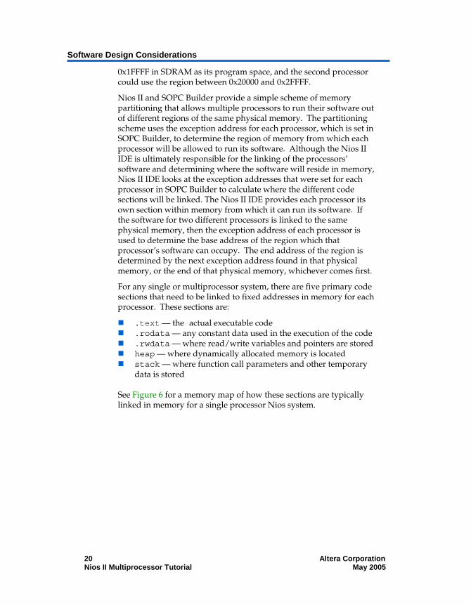
0x1FFFF in SDRAM as its program space, and the second processor could use the region between 0x20000 and 0x2FFFF.
Nios II and SOPC Builder provide a simple scheme of memory partitioning that allows multiple processors to run their software out of different regions of the same physical memory. The partitioning scheme uses the exception address for each processor, which is set in SOPC Builder, to determine the region of memory from which each processor will be allowed to run its software. Although the Nios II IDE is ultimately responsible for the linking of the processors’ software and determining where the software will reside in memory, Nios II IDE looks at the exception addresses that were set for each processor in SOPC Builder to calculate where the different code sections will be linked. The Nios II IDE provides each processor its own section within memory from which it can run its software. If the software for two different processors is linked to the same physical memory, then the exception address of each processor is used to determine the base address of the region which that processor’s software can occupy. The end address of the region is determined by the next exception address found in that physical memory, or the end of that physical memory, whichever comes first.
For any single or multiprocessor system, there are five primary code sections that need to be linked to fixed addresses in memory for each processor. These sections are:
.text — the actual executable code .rodata — any constant data used in the execution of the code .rwdata — where read/write variables and pointers are stored heap — where dynamically allocated memory is located stack — where function call parameters and other temporary
data is stored
See Figure 6 for a memory map of how these sections are typically linked in memory for a single processor Nios system.
20 Altera Corporation Nios II Multiprocessor Tutorial May 2005

Nios II Multiprocessor Tutorial
Figure 6: Single Processor Code Linked in Memory Map
1 Mbyte Memory
0x00FFFFF
0x00000000
stack
heap
.rwdata
.rodata
.text
In a multiprocessor system, it may be desirable to use a single memory to store all the code sections for each processor. In this case, the exception address set for each processor in SOPC Builder is used to define the boundaries between where one processor’s code sections end and where the next processor’s code sections begin.
For instance, imagine a system where SDRAM occupies the address range 0x0 – 0xFFFFF and processors A, B and C each need 64 Kbytes of SDRAM to run their software. By using SOPC Builder to set their exception addresses 64 Kbytes apart in SDRAM, Nios II IDE will automatically partition SDRAM based on those exception addresses. See Figure 7 for a memory map showing how the SDRAM will be partitioned in this example system.
Altera Corporation 21 May 2005 Nios II Multiprocessor Tutorial

Software Design Considerations
Figure 7: Partitioning of SDRAM Memory Map for Three Processors
0x00000000
0x00FFFFF
1Mbyte Memory
.text
.rodata
.rwdata
heap
stack
Processor 1
Processor 2
Processor 3
.text
.rodata
.rwdata
heap
stack
.text
.rodata
.rwdata
heap
stack
Processor 2ExceptionAddress
0x00020000
0x00010000
Processor 3Exception Address
Processor 1ExceptionAddress
Note that the lower six bits of the exception address are always set to 0x20. Offset 0x0 is where Nios II must run its reset code, so the exception address must be placed elsewhere. The offset of 0x20 is chosen because it corresponds to one instruction cache line. The 0x20 bytes of reset code initializes the instruction cache, and then branches around the exception section to the system startup code.
Care must be taken when partitioning a physical memory to contain the code sections of multiple processors. There are no safeguards in SOPC Builder or Nios II IDE that guarantee you have provided enough code space for each processor’s stack and heap in the partition. If inadequate code space is allotted in memory, the stack and heap may overflow and corrupt the processor’s code execution.
22 Altera Corporation Nios II Multiprocessor Tutorial May 2005

Nios II Multiprocessor Tutorial
Boot Addresses
In multiprocessor systems, each processor must boot from its own piece of memory. More than one processor may not boot from the same bit of executable code at the same address in the same non-volatile memory. Boot memory can also be partitioned, much like program memory can, but the notion of sections and linking is not a concern as boot code typically just copies the real program code to where it has been linked in RAM, and then branches to the program code. To boot multiple processors out of separate regions with the same non-volatile memory device, simply set each processor’s reset address to the location from where you wish to boot that processor. Be sure you leave enough space between boot addresses to hold the intended boot payload. See Figure 8 for a memory map of one physical flash device from which three processors can boot.
Altera Corporation 23 May 2005 Nios II Multiprocessor Tutorial

Software Design Considerations
Figure 8: Flash Device Memory Map with Three Processors Booting
0x00000000
0x00FFFFF
1Mbyte Flash Memory
Boot Loader
Program DataProcessor 1
Processor 2
Processor 3
0x0000FFFF
0x0001FFFF0x00020000
0x00010000 Boot loader
Program Data
Boot Loader
Program Data
Boot Loader
Nios II Flash Programmer is able to program bootable code for multiple processors into a single flash device. The flash programmer looks at the reset address of each processor and then uses that reset address to calculate the offset within the flash where the code will be programmed. See the Nios II Flash Programmer User Guide for details about the flash programmer.
24 Altera Corporation Nios II Multiprocessor Tutorial May 2005

Nios II Multiprocessor Tutorial
Running & Debugging Multiprocessor Systems from the Nios II IDE
The Nios II IDE includes a number of features that can help in the development of software for multiprocessor systems. Most notable is the ability of the Nios II IDE to perform simultaneous on-chip debug for multiple processors. Multiple debug sessions can run at the same time on a multiprocessor system and can pause and resume each processor independently. Breakpoints can also be set individually per processor, so if one processor hits a breakpoint, it will not halt or affect the operation of the other processors. Lastly, debug sessions can be launched and stopped independently.
Debug sessions for multiple processors can also be launched in a single operation with the Nios II IDE, using a feature called multiprocessor collections. Multiprocessor collections are groups of debug configurations for individual processors that are combined under one configuration name. The benefit of a multiprocessor collection is that any time the collection is launched; the Nios II IDE individually launches each of the single debug configurations in the background. This allows users to launch debug sessions for multiprocessor systems without having to manually launch a session for each processor. Multiprocessor collections can also be stopped with one operation, however pausing and resuming multiprocessor collections together is not currently supported.
The launching and stopping of multiprocessor collections is not simultaneous, meaning the processors in the collection do not start executing code on the same clock cycle. In fact, there may be a delay of a few seconds between the individual processors being started. The purpose of multiprocessor collections is to make it more convenient to launch debug sessions for multiprocessor systems, not to synchronize the processors. If you want the multiple processors to start within a shorter period of time, a separate hardware or software mechanism will need to be constructed to enable this.
Altera Corporation 25 May 2005 Nios II Multiprocessor Tutorial

Software Design Considerations
26 Altera Corporation Nios II Multiprocessor Tutorial May 2005
Building & Running Software on a Nios II
Multiprocessor
Altera Corporation 27 May 2005
Introduction
In this Tutorial, you will build a 3-processor Nios II system with SOPC Builder, starting with the standard example design as a template. Next, you will create 3 software projects in the Nios II IDE, one for each processor. The software for all 3 CPUs will generate messages to be displayed and use the hardware mutex core to put those messages in a shared message buffer. cpu1 will continually check the message buffer for new messages, and if it finds one, will print it using the jtag_uart.
Hardware and Software Requirements
To use the design example in this tutorial, you must have the following:
Quartus II Software version 5.0 or higher – Both Quartus II Web Edition and the fully licensed version will work with the example design.
Nios II Development Kit version 5.0 or higher – There are five available kits which include a Nios development board and an Altera USB Blaster download cable (optional). You can use any of the following Nios II Development Kits:
Stratix II Edition Stratix Edition Stratix Professional Edition Cyclone II Edition Cyclone Edition
If you do not have a development board, you can follow the hardware development steps, but you will not be able to download the complete system to a working board.
f You can download the Quartus II Web Edition software and the Nios II Development Kit, Evaluation Edition for free from the Altera Download Center at www.altera.com.
Before you begin, you must install the Quartus II software and Nios II development tools.

Creating the Hardware System
28 Altera Corporation Nios II Multiprocessor Tutorial May 2005
Creating the Hardware System
In the following steps you will create a multiprocessor system by starting with the standard hardware example design included in the Nios II development kit, and adding two additional processors, two additional timers, and a hardware mutex component. You can use the standard hardware example design for any of the Nios development boards, and the resulting system will run on that development board. If you do not have a Nios development board, you can still follow these steps to learn how to design multiprocessor hardware.
Getting Started with a Standard Example Design
To begin building a multiprocessor system sharing resources, perform the following steps:
Browse to the examples directory for your board. Each of the board-specific project files are found in the following directory: <Nios II kit path>\examples\ \<Dev.Kit Device>\standard.qpf. Table 1 lists the names of the board-specific directories and Quartus II project file.

Nios II Multiprocessor Tutorial
Altera Corporation 29 May 2005 Nios II Multiprocessor Tutorial
Table 1: Project File Directory
Nios Development Board Board-Specific Directory Project File for Microprocessor Tutorial
Stratix II Edition niosII_stratixII_2s60_es standard.qpf
Stratix Edition niosII_stratix_1s10 & niosII_stratix_1s10_es
standard.qpf
Stratix Professional Edition niosII_stratix_1s40 standard.qpf
Cyclone II Edition niosII_cycloneII_2c35 standard.qpf
Cyclone Edition niosII_cyclone_1c20 standard.qpf
1. Copy the standard example design project directory for the board you are using to a working directory named C: /Multiprocessor_Tutorial or to a directory of your choice. Make sure the path has no spaces.
2. Open the Quartus II software.
3. Open the standard.qpf project file from the newly-created directory.
4. Choose SOPC Builder (Tools).
c In this tutorial, you must name the hardware components exactly. If your component names differ from the names printed here, the software example will not work.
5. Right click cpu and select Rename.
6. Type cpu1 to rename the processor then press Enter.
7. Right click sys_clk_timer and select Rename.
8. Type cpu1_timer and press Enter. This will be your timer for cpu1.

Creating the Hardware System
30 Altera Corporation Nios II Multiprocessor Tutorial May 2005
9. Click Move Up to move cpu1_timer under cpu1.
Adding a Second Processor
In the next series of steps, you will add a second Nios II processor to the system. A Nios II/s will be added because it is a good general-purpose choice.
To add a second processor, perform the following steps:
1. Double click Nios II Processor – Altera Corporation in the list of available components to add a second Nios II processor to the system. Once selected, the Nios II Core wizard is displayed.
2. Select NiosII/s as the type of processor and click Finish.
3. Click the JTAG Debug Module tab.
4. Select Level 1 as the debugging level for this processor and click Finish.
You will see error messages in the SOPC Builder messages window. This is because SOPC Builder does not know that you plan to connect this processor with other components in the system. Ignore the error messages for now. You will fix these errors in later steps.
5. Right click the newly-added processor and select Rename.
6. Type cpu2 and press Enter.
7. Use Move Up to move cpu2 under cpu1_timer.
Adding a Third Processor
In the next series of steps, you will add a third Nios II processor to the system. An economy (NiosII/e) variety of Nios II will be added to demonstrate that any Nios II variety processor can be used in a multiprocessor system.
To add the third processor, perform the following steps:
v Repeat steps 1-9 above to add a third Nios II processor with the following exceptions:
Nios II Multiprocessor Tutorial
Altera Corporation 31 May 2005 Nios II Multiprocessor Tutorial
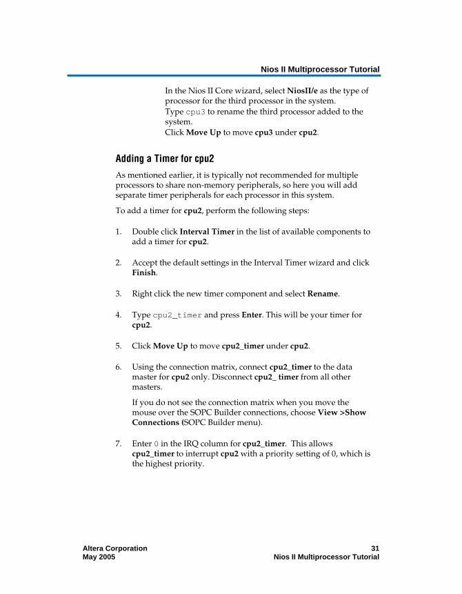
In the Nios II Core wizard, select NiosII/e as the type of processor for the third processor in the system.
Type cpu3 to rename the third processor added to the system.
Click Move Up to move cpu3 under cpu2.
Adding a Timer for cpu2
As mentioned earlier, it is typically not recommended for multiple processors to share non-memory peripherals, so here you will add separate timer peripherals for each processor in this system.
To add a timer for cpu2, perform the following steps:
1. Double click Interval Timer in the list of available components to add a timer for cpu2.
2. Accept the default settings in the Interval Timer wizard and click Finish.
3. Right click the new timer component and select Rename.
4. Type cpu2_timer and press Enter. This will be your timer for cpu2.
5. Click Move Up to move cpu2_timer under cpu2.
6. Using the connection matrix, connect cpu2_timer to the data master for cpu2 only. Disconnect cpu2_ timer from all other masters.
If you do not see the connection matrix when you move the mouse over the SOPC Builder connections, choose View >Show Connections (SOPC Builder menu).
7. Enter 0 in the IRQ column for cpu2_timer. This allows cpu2_timer to interrupt cpu2 with a priority setting of 0, which is the highest priority.

Creating the Hardware System
32 Altera Corporation Nios II Multiprocessor Tutorial May 2005
Adding a Timer for cpu3
To add a timer for cpu3, perform the following steps:
1. Double Click Interval Timer in the list of available components to add a timer for cpu3.
2. Accept the default setting in the Interval Timer wizard and click Finish.
3. Right click the new timer component and select Rename.
4. Type cpu3_timer and press Enter. This will be your timer for cpu3.
5. Click Move Up to move cpu3_timer under cpu3.
6. Using the connection matrix, connect cpu3_timer to the data master for cpu3 only. Disconnect cpu3_timer from all other masters.
7. In the IRQ column for cpu3_timer, enter 0. This allows cpu3_timer to interrupt cpu3 with a priority setting of 0. This is the highest priority.
Adding a Hardware Mutex
You are building a multiprocessor system that shares a data memory between processors, so it is essential that a hardware mutex component be included to enable protection of that memory from data corruption.
To add the hardware mutex, perform the following steps:
1. Double click Mutex under Others in the list of available components to add a mutex core to the system.
2. Accept the defaults in the Mutex wizard and click Finish.
3. Right click Mutex and select Rename.
4. Type message_buffer_mutex and press Enter.

Nios II Multiprocessor Tutorial
Altera Corporation 33 May 2005 Nios II Multiprocessor Tutorial
5. Using the connection matrix, connect message_buffer_mutex to the data masters for each processor. This allows all three processors to access message_buffer_mutex.
Adding a Message Buffer Memory
Here you will add an on-chip memory to the system that will be used as a message buffer to pass messages between processors. This memory will be shared by all processors in the system. The processors will use the mutex core added in the previous steps to protect the memory’s contents from corruption.
To add a message buffer memory perform the following steps:
1. Double click On-chip Memory under Memory in the list of available components. The On-Chip Memory wizard is displayed.
2. Under Size, type 1 and select Kbytes in the Total Memory Size box.
3. Click Finish.
4. Right click on-chip memory_0 and select Rename.
5. Type message_buffer_ram and press Enter. This memory will be used as a message buffer for the three processors in your multiprocessor system.
Connecting Shared Resources
Now you need to connect all the resources that will be shared between processors in the system using SOPC Builder’s connection matrix.
To connect all the resources in the system shared by the multiple processors, perform the following steps:
1. Using the connection matrix, connect sdram to the instruction and data masters for each processor, allowing all three processors to access sdram.
All the connection dots for the sdram should be solid black.

Creating the Hardware System
34 Altera Corporation Nios II Multiprocessor Tutorial May 2005
2. Using the connection matrix, connect ext_ram_bus to the instruction and data masters for each processor, allowing all three processors to access external RAM and FLASH.
3. All the connection dots for ext_ram_bus should be solid black.
4. Using the connection matrix, connect message_buffer_ram to the data masters for each processor, allowing all three processors to access that memory.
5. Remove the default connection between message_buffer_ram and the cpu1 instruction master, as no software will be run from message_buffer_ram.
6. Choose System > Auto-Assign Base Addresses to give every peripheral a unique base address.
Figure 9 shows you what your system should look like after completing the tutorial up to this point.
Figure 9: Connect Shared Resource Example

Nios II Multiprocessor Tutorial
Altera Corporation 35 May 2005 Nios II Multiprocessor Tutorial
Setting Reset and Exception Addresses
In the following steps, you will set the reset and exception addresses for all three processors. If you recall from Program Memory on page 9 the exception addresses are what determine how code memory is partitioned between processors. In this tutorial, each of the three processors will run its software from 1Mbyte of SDRAM, so you will set each processor’s exception address within SDRAM, each separated by 0x100000 (1Mbyte).
Setting Reset and Exception Addresses for cpu1
To set the Reset and Exception Addresses for cpu1, perform the following steps:
v Click the “More “cpu1” settings” tab and set the Memory Module and Offset fields to match Table 2.
Table 2: cpu1 Reset & Exception Addresses
Processor Function
Memory Module
Offset Address
Reset Address
ext_flash 0x00000000 0x00000000
Exception Address
sdram 0x00000020 0x01000020
Setting Reset and Exception Addresses for cpu2
To set the Reset and Exception Addresses for cpu2, perform the following steps:
v Click the “More “cpu2” settings” tab and set the Memory Module and Offset fields to match Table 3.
Table 3: cpu2 Reset & Exception Addresses
Processor Function
Memory Module
Offset Address
Reset Address
ext_flash 0x00100000 0x00100000
Exception Address
sdram 0x00100020 0x01100020

Creating the Hardware System
36 Altera Corporation Nios II Multiprocessor Tutorial May 2005
Setting Reset and Exception Addresses for cpu3
To set the Reset and Exception Addresses for cpu3, perform the following steps:
v Click the “More “cpu3” settings” tab and set the Memory Module and Offset fields to match Table 4.
Table 4: cpu3 Reset & Exception Addresses
Processor Function
Memory Module
Offset Address
Reset Address
ext_flash 0x00200000 0x00200000
Exception Address
sdram 0x00200020 0x01200020
Generating and Compiling the System
Here you will generate HDL for the system you just constructed in SOPC Builder, and then compile the project in Quartus to produce a programming file. To generate and compile the system, perform the following steps:
1. Click Generate.
2. When generation is complete, click Exit in SOPC Builder. This returns you to the Quartus II software. This may take a few moments.
3. If not automatically prompted to do so, update the system symbol by right clicking and selecting Update Symbol.
Notice that the symbol did not change. SOPC Builder was able to easily connect this complex, multiprocessor system without making any external changes to the system. With very little effort, a single-processor system has been turned into a pin-compatible three-processor system.
4. Select File > Save to save the Block Diagram File (.bdf) file.
5. Select Start Compilation (Processing menu) to compile the project in Quartus II.
6. When compilation is finished, select Programmer (Tools menu).

Nios II Multiprocessor Tutorial
Altera Corporation 37 May 2005 Nios II Multiprocessor Tutorial
7. Choose standard.sof as a programming file.
8. Turn on the Program/Configure checkbox in the programmer and click Start.
Creating Software for the Multiprocessor System
In the following steps you will create six separate software projects for the multiprocessor system, one application project and one system library project for each processor in the system. You will then build, run and debug those software projects using Nios II IDE.
The software you will be running on this system uses the hardware mutex to share a message buffer. All three processors write messages to the message buffer. cpu1 then reads the messages and prints them to the jtag_uart. You will notice that the same C file is run on each processor, but the processors are doing slightly different things. The way this is achieved is through the use of the cupid feature of Nios II. In Nios II processor systems, a processor locks the mutex by writing the value of its cpuid control register to the OWNER field of the mutex register. The cpuid register holds a static value that uniquely identifies the processor in a multi-processor system. The software checks the processor’s cpuid before executing any functions that are specific to a particular processor. If the cpuid is correct, it will execute the function.
Starting the Nios II IDE
Here you will start Nios II IDE and begin creating software projects for the three processors in the system. To start the Nios II IDE from SOPC Builder, perform the following steps:
1. Choose SOPC Builder (Tools menu).
2. Click the System Generation tab.
3. Click Run Nios II IDE.
1 If the Nios II IDE welcome screen is displayed, click Workbench to continue.

Creating Software for the Multiprocessor System
38 Altera Corporation Nios II Multiprocessor Tutorial May 2005
Creating a Software Project for cpu1
Here you will create software projects to run on each of the three processors in the system. The software will use the mutex to place messages in the message buffer to later be retrieved and printed by cpu1.
To create a software project for cpu1, perform the following steps:
1. When the Nios II IDE opens, choose File > New > Project.
2. Select C/C++ Application and click Next.
3. In the Name field, type hello_multi_cpu1.
4. Under Select Target Hardware, specify cpu1 as the processor.
5. In Select Project Template list, select Blank Project as shown in Figure 10.

Nios II Multiprocessor Tutorial
Altera Corporation 39 May 2005 Nios II Multiprocessor Tutorial
Figure 10: New Project for cpu1
6. Click Finish. The Nios II IDE will generate a new C/C++ application project, and a corresponding system library project for cpu1.
7. Browse to the file hello_world_multi.c on the host PC.
1 This file is found with the Nios II Multiprocessor Tutorial on the Nios II Processor Literature page from www.altera.com/literature.
8. Right click hello_world_multi.c and select copy.

Creating Software for the Multiprocessor System
40 Altera Corporation Nios II Multiprocessor Tutorial May 2005
9. Return to the Nios II IDE.
10. Click the Navigator tab next to the C/C++ Projects tab.
11. Right click the hello_multi_cpu1 project and select paste to paste the copied C file into the project.
12. Right click the system library project hello_multi_cpu1_syslib.
13. Select Properties.
14. In the left-hand window, select System Library.
15. Select jtag_uart as stdin, stderr, and stdout.
16. Select cpu1_timer as the System clock timer.
17. Verify that sdram is selected for Program memory, Read-only data memory, Read/write data memory, Heap memory, and Stack memory. See Figure 11 for an example of system library property settings.
18. Click OK.
Figure 11: System Library Property Settings

Nios II Multiprocessor Tutorial
Altera Corporation 41 May 2005 Nios II Multiprocessor Tutorial
Creating a Software Project for cpu2
To create a software project for cpu2, perform the following steps:
1. Choose File > New > Project.
2. Select C/C++ Application and click Next.
3. In the Name field, type hello_multi_cpu2.
4. Under Select Target Hardware, specify cpu2 as the processor.
5. In Select Project Template, choose Blank Project.
6. Click Finish.
The Nios II IDE will generate a new C/C++ application project, and a corresponding system library project for cpu2.
7. In the host PC file system, browse to the file hello_world_multi.c.
1 This file is found with the Nios II Multiprocessor Tutorial on the Nios II Processor Literature page from www.altera.com/literature.
8. Right click hello_world_multi.c and select copy.
9. Return to Nios II IDE and highlight the new project hello_multi_cpu2.
10. Click the Navigator tab next to the C/C++ Projects tab.
11. Right click the hello_multi_cpu2 project and select paste to paste the copied C file into the project.
12. Right click the system library project hello_multi_cpu2_syslib.
13. Select Properties.
14. Select System Library in the left-hand window.
15. Select cpu2_timer as System clock timer.

Creating Software for the Multiprocessor System
42 Altera Corporation Nios II Multiprocessor Tutorial May 2005
16. Verify null is selected for stdin, stderr, and stdout since this processor is not connected to the jtag_uart.
17. Verify that sdram is selected for Program Memory, Read-only data memory, Read/write data memory, Heap memory, and Stack memory.
18. Click OK.
Creating a Software Project for cpu3
To create a software project for cpu3, perform the following steps:
1. Choose File > New > Project.
2. Select C/C++ Application and click Next.
3. In the Name field, type hello_multi_cpu3.
4. Under Select Target Hardware, specify cpu3 as the processor.
5. In Select Project Template, choose Blank Project.
6. Click Finish.
The Nios II IDE will generate a new C/C++ application project, and a corresponding system library project for cpu3.
7. In the host PC file system, browse to the file hello_world_multi.c.
1 This file is found with the Nios II Multiprocessor Tutorial on the Nios II Processor Literature page from www.altera.com/literature.
8. Right click hello_world_multi.c and select copy.
9. Return to Nios II IDE and highlight the new project hello_multi_cpu3.
10. Click the Navigator tab next to the C/C++ Projects tab.
11. Right click the hello_multi_cpu3 project and select paste to paste the copied C file into the project.

Nios II Multiprocessor Tutorial
Altera Corporation 43 May 2005 Nios II Multiprocessor Tutorial
12. Right click system library project hello_multi_cpu3_syslib.
13. Select Properties.
14. Select System Library in the left-hand window.
15. Select cpu3_timer as System clock timer.
16. Verify null is selected for stdin, stderr, and stdout since this processor is not connected to the jtag_uart.
17. Verify that sdram is selected for Program memory, Read-only data memory, Read/write data memory, Heap memory, and Stack memory.
18. Click OK.
Building the Software Projects
Here you will build the three software projects you just created so they can be run on the processors in the system.
To build the three software projects, perform the following steps:
1. Click the C/C++ Projects tab at the top of the projects window in Nios II IDE
2. Right click the project hello_multi_cpu1 and select Build Project.
3. Right click the project hello_multi_cpu2 and select Build Project.
4. Right click the project hello_multi_cpu3 and select Build Project.
If you encounter any errors in the builds, you must correct them and rebuild before continuing.
Setting up the Nios II IDE for Multiprocessor Debug
By default the Nios II IDE is set to not allow multiple active debug sessions. To enable multiple debug sessions, perform the following steps:

Creating Software for the Multiprocessor System
44 Altera Corporation Nios II Multiprocessor Tutorial May 2005
1. In the Nios II IDE, choose Window > Preferences.
2. Select Nios II and turn on Allow multiple active run/debug sessions as shown in Figure 12.
3. Click OK.
Figure 12: Multiple Active Run/Debug Sessions
Creating a Debug Configuration for Each Processor
Here, you will create a run/debug configuration for each of the target processors, which enable the running and debugging of the three software projects you just built on the processors in the system.
To create debug configurations for each processor, perform the following steps:
1. Select the hello_multi_cpu1 project.
2. Choose Run… (Run menu).
3. Select Nios II Hardware in the Configuration list.
4. Click New in the lower left corner of the Run window.
5. Click the Target Connection tab.

Nios II Multiprocessor Tutorial
Altera Corporation 45 May 2005 Nios II Multiprocessor Tutorial
6. Ensure the download cable you are using is selected in the JTAG cable field as shown in Figure 13.
If the field reads Automatic<currently (your correct download cable)>, this is fine. You do not need to change it.
Figure 13: Create Debug Configuration
7. Click Apply then click Close.
8. Repeat steps 1 – 7 to create a run/debug configuration for each of the target processors.
w Be sure you have selected the appropriate project when you create the run/debug configuration.
At this point, you have created a run/debug configuration for each processor in the system. You can now download, execute, and debug code on each of the processors individually, using the normal flow for running/debugging.

Creating Software for the Multiprocessor System
46 Altera Corporation Nios II Multiprocessor Tutorial May 2005
Creating a Multiprocessor Collection
Here you will create a multiprocessor collection which enables the launching and stopping of multiple processors as a single unit
To create this multiprocessor collection, perform the following steps:
1. Choose Run… (Run menu)
2. In the Configurations list, select Nios II Multiprocessor Collection.
3. Click New in the lower left corner of the Run window.
4. In the Name field, Type hello_cpu_collection as the name for this new multiprocessor collection.
5. Turn on hello_multi_cpu1 Nios II HW configuration, hello_multi_cpu2 Nios II HW configuration, and hello_multi_cpu3 Nios II HW configuration as shown in Figure 14.
6. Click Apply.
Figure 14: Multiprocessor Collection Example

Nios II Multiprocessor Tutorial
Altera Corporation 47 May 2005 Nios II Multiprocessor Tutorial
Starting the Multiprocessor Collection
Now you can start all the processors with a single mouse click. To start all the processors, perform the following steps:
1. Select the hello_cpu_collection configuration, and click Run. The Nios II IDE downloads the software to each processor, and then runs the software
Each processor begins executing code as soon as its code is downloaded; the processors do not start in unison.
2. After the launch finishes, you should see messages from all three processors being displayed on the terminal as shown in Figure 15.
Figure 15: Multiprocessor Collection Messages
3. When you are done observing the terminal output, click the red square button (stop) above the terminal to close the terminal connection.
Debugging the Software Projects on the Board
In this section you will start all the processors using the multiprocessor collection, and set breakpoints on individual
Creating Software for the Multiprocessor System
48 Altera Corporation Nios II Multiprocessor Tutorial May 2005
processors. To start the processors and set individual breakpoints, perform the following steps:
1. Choose Debug (Run menu).
2. In the configurations list on the left, select the new collection you created under Nios II multiprocessor collection in the previous section.
3. Click Debug.
1 If a dialog box appears and asks you to switch to the debug perspective, click Yes.
Again, Nios II IDE will download and launch each software project on its respective processor, then pause each one at a breakpoint set on main().
In the Debug view, you will see the processor collection listed at the top with each individual debug session listed below it, including the call stack.
4. Click the main call stack entry under the cpu1 debug session.
5. Click step over in the toolbar menu to see cpu1 step through its software commands.
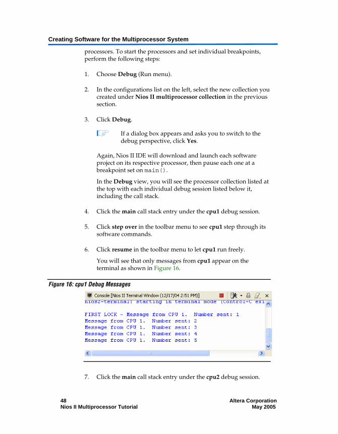
6. Click resume in the toolbar menu to let cpu1 run freely.
You will see that only messages from cpu1 appear on the terminal as shown in Figure 16.
Figure 16: cpu1 Debug Messages
7. Click the main call stack entry under the cpu2 debug session.

Nios II Multiprocessor Tutorial
Altera Corporation 49 May 2005 Nios II Multiprocessor Tutorial
8. Click resume in the toolbar menu to let cpu2 run uninterrupted.
You will now see that messages from both cpu1 and cpu2 appear on the terminal as shown in Figure 17.
Figure 17: cpu1& cpu2 Debug Output
9. In the Debug view, click the multiprocessor collection at the top of the list.
10. Click the red square button (stop) to stop the debug sessions for all three processors.
You’re done! You’ve now constructed, built software projects for, and debugged software on your first Nios II multiprocessor system. You have also learned how to use the Mutex component to share system resources between processors. Feel free to experiment with the system you’ve created and find interesting new ways of using multiple processors in an Altera FPGA.
We recommend you save this system to use as a starting point next time you wish to create a multiprocessor system.

Creating Software for the Multiprocessor System
50 Altera Corporation Nios II Multiprocessor Tutorial May 2005