Crashworthiness and Ditching Behavior of Blended...
13
1 Crashworthiness and Ditching Behavior of Blended Wing Body (BWB) Aircraft Design Ralf Sturm 1) • Martin Hepperle 2) 1) Institute of Structures and Design, German Aerospace Center (DLR), Germany 2) Institute of Aerodynamics and Flow Technology, German Aerospace Center (DLR), Germany Abstract Over the last decades fuel efficiency of aircraft was mainly improved by the application of refined aerodynamics, new materials, structural optimization and enhanced engine performance. A further potential for a greener aircraft is seen in the unconventional blended wing body design configuration due to its advanced aerodynamic design and its reduced weight. For the certification of novel aircraft configurations the airworthiness authorities require proof of at least equivalent safety standards compared to existing conventional transport aircraft. In this context the BWB configuration has to demonstrate sufficient crashworthiness for emergency landing on rigid surface and on water. Since structural modifications for improved safety should be applied in the early conceptual design phase of an aircraft, explicit simulations have been performed with the objective to estimate the crash behavior of the BWB configuration. Based on the simulation results design principles are derived for improved crashworthiness and ditching behavior for the BWB aircraft configuration. 1. Introduction Even though prediction of future air traffic is difficult, all statistics assume a continuous increase of air traffic while the number of takeoffs and landings at large airports is limited [4]. For the `hub and spoke´ principle in which the passengers travel between central hubs aircraft with high passenger capacity are required. Thus engineers are looking for a novel aircraft configuration with high payload capacity, enhanced aerodynamic efficiency and lower carbon dioxide emission per passenger. Current transport aircraft follow the `tube and wing´ design in which the passengers are located in a cylindrical pressure vessel, while the lift is generated separately by wings on each side of the fuselage. The blended wing body (BWB) aircraft configuration offers the potential to revolutionize current aircraft design by blending fuselage and wing into one lifting surface. Even though the BWB is seen as unconventional, the aerodynamic benefits of aerodynamically shaped fuselages have been known for almost one century. Wood [15] cataloged over one hundred developed flying wing and BWB aircraft. While most aircraft were built for military purposes, Junkers and Burnelli have to be mentioned to be one of the first aircraft designers who recognized the potential of this configuration for the application in civil transport [16]. In recent history different research studies were launched to investigate the BWB design for civil transport. An overview of the identified potentials and risks of the BWB design is given by Liebeck [10]. Bolsunovsky et al. [2] and Dmitirev et al. [5] investigated different BWB type aircraft configurations and compared their characteristics with conventional aircraft design. Besides the design studies from NASA and Boeing [10] research projects were launched by the European Union to foster the technological development for a civil BWB transport aircraft and to support the research on environmental friendly aircraft configurations for the future civil air transport. In the Very Efficient Large Aircraft (VELA) project different configurations were investigated and brought together in a final configuration by maximizing the advantages and minimizing the disadvantages.
Transcript of Crashworthiness and Ditching Behavior of Blended...

1
Crashworthiness and Ditching Behavior of Blended Wing Body (BWB) Aircraft Design
Ralf Sturm 1) • Martin Hepperle 2)
1) Institute of Structures and Design, German Aerospace Center (DLR), Germany
2) Institute of Aerodynamics and Flow Technology, German Aerospace Center (DLR), Germany Abstract Over the last decades fuel efficiency of aircraft was mainly improved by the application of refined aerodynamics, new materials, structural optimization and enhanced engine performance. A further potential for a greener aircraft is seen in the unconventional blended wing body design configuration due to its advanced aerodynamic design and its reduced weight. For the certification of novel aircraft configurations the airworthiness authorities require proof of at least equivalent safety standards compared to existing conventional transport aircraft. In this context the BWB configuration has to demonstrate sufficient crashworthiness for emergency landing on rigid surface and on water. Since structural modifications for improved safety should be applied in the early conceptual design phase of an aircraft, explicit simulations have been performed with the objective to estimate the crash behavior of the BWB configuration. Based on the simulation results design principles are derived for improved crashworthiness and ditching behavior for the BWB aircraft configuration. 1. Introduction Even though prediction of future air traffic is difficult, all statistics assume a continuous increase of air traffic while the number of takeoffs and landings at large airports is limited [4]. For the `hub and spoke´ principle in which the passengers travel between central hubs aircraft with high passenger capacity are required. Thus engineers are looking for a novel aircraft configuration with high payload capacity, enhanced aerodynamic efficiency and lower carbon dioxide emission per passenger. Current transport aircraft follow the `tube and wing´ design in which the passengers are located in a cylindrical pressure vessel, while the lift is generated separately by wings on each side of the fuselage. The blended wing body (BWB) aircraft configuration offers the potential to revolutionize current aircraft design by blending fuselage and wing into one lifting surface. Even though the BWB is seen as unconventional, the aerodynamic benefits of aerodynamically shaped fuselages have been known for almost one century. Wood [15] cataloged over one hundred developed flying wing and BWB aircraft. While most aircraft were built for military purposes, Junkers and Burnelli have to be mentioned to be one of the first aircraft designers who recognized the potential of this configuration for the application in civil transport [16]. In recent history different research studies were launched to investigate the BWB design for civil transport. An overview of the identified potentials and risks of the BWB design is given by Liebeck [10]. Bolsunovsky et al. [2] and Dmitirev et al. [5] investigated different BWB type aircraft configurations and compared their characteristics with conventional aircraft design. Besides the design studies from NASA and Boeing [10] research projects were launched by the European Union to foster the technological development for a civil BWB transport aircraft and to support the research on environmental friendly aircraft configurations for the future civil air transport. In the Very Efficient Large Aircraft (VELA) project different configurations were investigated and brought together in a final configuration by maximizing the advantages and minimizing the disadvantages.

2
The global crash and ditching analyses described in this paper are based on the final VELA BWB configuration and the structural definitions developed in the subsequent New Aircraft Configurations Research (NACRE) project. The VELA BWB is a very large aircraft with a wing span of about 100 m. The aircraft measures over 60 m from the nose to tail. The maximum take‐off weight of the aircraft was assessed to be approximately 700 tons. Depending on the seating, the VELA BWB may have more than 1000 passengers. Even with a typical 3 class seating (3% first class, 18% business class and 79% economy class), the aircraft still has a passenger capacity of 750. All passengers are seated on one deck in 4 longitudinal bays. The bays of the centerbody are separated by framework ribs. The primary challenge from the structural point of view is the pressurized centerbody [1,3,11,12]. For the conventional fuselage, the cabin pressure is taken by tension hoop load which represents the best way to withstand pressure forces. For the BWB centerbody, where an aerodynamically flatter fuselage shape is required, this design philosophy cannot be applied. In Figure 1 the change in the fuselage cross‐sectional shape from a conventional to BWB aircraft configurations is presented. The NACRE design follows a rather conventional design approach of a monolithic fuselage design. The skin is stiffened by longitudinal stringers and circumferential frames, designed to withstand aerodynamic and pressure loads.
Figure 1: Change of the fuselage cross‐section from the tube and wing design to different BWB designs The main objective of the global crash investigation, presented herein, is a qualitative evaluation of the crash and ditching behavior of a BWB aircraft and additionally the identification of highly loaded structural components which could play a significant role during crash and ditching. The understanding of the load flow during impact aims to support the development of energy absorption strategies for enhanced crashworthiness. 2. Simulation model 2.1 Model description The NACRE BWB design was used as baseline configuration for the global crash and ditching simulations. Structural sizing of the fuselage and outer wing was performed within the VELA and NACRE projects [9,13]. For this purpose relatively simple global Finite Element (FE) models were generated. The preliminary sizing of the structural components was based on only three basic load cases [13]. The considered load cases are summarized in Table 1. It is clear, that these correspond to a small selection of the load cases, which are necessary for the structural certification of an aircraft. Load cases like, for instance, hard landing, rapid decompression, horizontal and vertical crash have significant influence on the structural design. Since the main objective of the global FE model was a preliminary assessment of the structural weight and structural concepts, the FE model does not accurately represent the structural design of the BWB aircraft.

3
Table 1 Considered load cases for structural sizing
Load case A (static)
cabin pressure with p = 2 pcabin
Load case B (static)
cabin pressure p = 1.5 pcabin , combined with maneuver loads (2,5 g)
Load case C (fatigue)
cabin pressure p = 3 pcabin (derived from an empirical coefficient corresponding to about 30 000 flights), combined with maneuver loads (2,5 g)
However, the FE model includes the main structural components of a BWB fuselage with smeared stiffness. Still, due to the preliminary maturity of the structural design the FE model has to be seen as rather generic. Nevertheless for a first evaluation of crashworthiness and ditching characteristics the developed design is sufficient to be used as basis for initial global crash investigations. A static FE model in the preliminary design phase does not feature all structural components which are required for a crash simulation. Therefore, additional structural components like passenger (PAX) deck, cargo floor, seats and landing gear bays were added to the global FE model. Figure 2 depicts the structural components which were added to the global FE model. The passenger deck and the cargo floor, which were not included in the static model, are of high importance for crash investigations, since the inertia loads of the passengers are transferred through the PAX floor to the impact zone. PAX floor grid structures based on a conventional widebody fuselage design were included in the crash model. A similar approach was used for the cargo floor. The cargo structure consists of crossbeams, vertical support struts and roller tracks. For this investigation, the complete fuselage structure was defined to be made completely out of 2024 aluminum alloy (VPS MATYP 103, Young’s modulus ≈ 72 GPa, yield stress ≈ 327 MPa).
Figure 2: Explicit FE model of the NACRE BWB aircraft
4
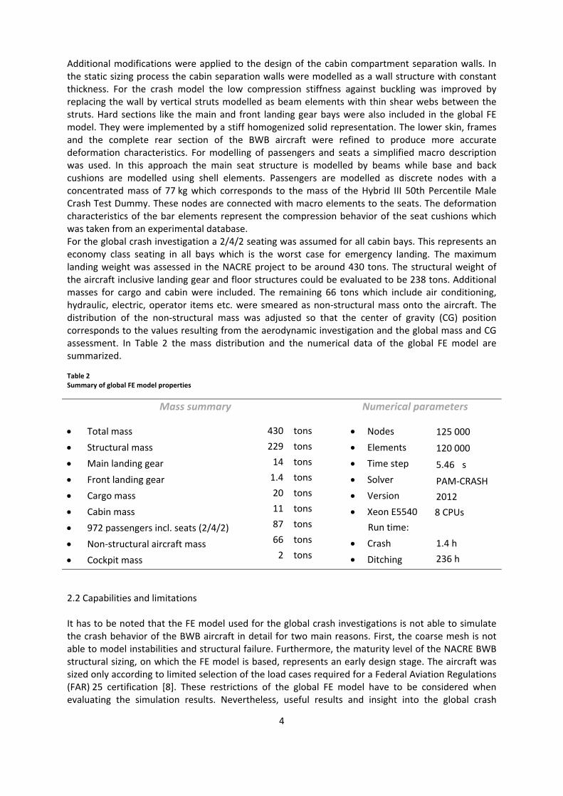
Additional modifications were applied to the design of the cabin compartment separation walls. In the static sizing process the cabin separation walls were modelled as a wall structure with constant thickness. For the crash model the low compression stiffness against buckling was improved by replacing the wall by vertical struts modelled as beam elements with thin shear webs between the struts. Hard sections like the main and front landing gear bays were also included in the global FE model. They were implemented by a stiff homogenized solid representation. The lower skin, frames and the complete rear section of the BWB aircraft were refined to produce more accurate deformation characteristics. For modelling of passengers and seats a simplified macro description was used. In this approach the main seat structure is modelled by beams while base and back cushions are modelled using shell elements. Passengers are modelled as discrete nodes with a concentrated mass of 77 kg which corresponds to the mass of the Hybrid III 50th Percentile Male Crash Test Dummy. These nodes are connected with macro elements to the seats. The deformation characteristics of the bar elements represent the compression behavior of the seat cushions which was taken from an experimental database. For the global crash investigation a 2/4/2 seating was assumed for all cabin bays. This represents an economy class seating in all bays which is the worst case for emergency landing. The maximum landing weight was assessed in the NACRE project to be around 430 tons. The structural weight of the aircraft inclusive landing gear and floor structures could be evaluated to be 238 tons. Additional masses for cargo and cabin were included. The remaining 66 tons which include air conditioning, hydraulic, electric, operator items etc. were smeared as non‐structural mass onto the aircraft. The distribution of the non‐structural mass was adjusted so that the center of gravity (CG) position corresponds to the values resulting from the aerodynamic investigation and the global mass and CG assessment. In Table 2 the mass distribution and the numerical data of the global FE model are summarized. Table 2 Summary of global FE model properties
Mass summary Numerical parameters
Total mass
Structural mass
Main landing gear
Front landing gear
Cargo mass
Cabin mass
972 passengers incl. seats (2/4/2)
Non‐structural aircraft mass
Cockpit mass
430
229
14
1.4
20
11
87
66
2
tons
tons
tons
tons
tons
tons
tons
tons
tons
Nodes
Elements
Time step
Solver
Version
Xeon E5540
Run time:
Crash
Ditching
125 000
120 000
5.46 �s
PAM‐CRASH
2012
8 CPUs
1.4 h
236 h
2.2 Capabilities and limitations It has to be noted that the FE model used for the global crash investigations is not able to simulate the crash behavior of the BWB aircraft in detail for two main reasons. First, the coarse mesh is not able to model instabilities and structural failure. Furthermore, the maturity level of the NACRE BWB structural sizing, on which the FE model is based, represents an early design stage. The aircraft was sized only according to limited selection of the load cases required for a Federal Aviation Regulations (FAR) 25 certification [8]. These restrictions of the global FE model have to be considered when evaluating the simulation results. Nevertheless, useful results and insight into the global crash

5
behavior can be obtained. Limitations and results of the global crash studies are summarized in Table 3. Table 3 Limitations and results of the global crash simulation
Limitations Results
Evaluation of exact structural failure
Modelling of joint failure
Exact prediction of quantitative values
Modelling of local instabilities
Simulation of detailed nonlinear material behavior
Assessment of global crash kinematics
Modelling of elastic structural behavior
Identification of highly loaded structural components
Qualitative distribution of structural loads
Load flow during impact
Sensitivity studies for different global crash parameters
3. Results and discussion 3.1. Crash investigation An aircraft configuration with retracted landing gear was selected for the crash simulations. This impact condition is seen as one of the worst survivable crash scenarios due the fact that the vertical share of the kinetic energy has to be absorbed completely by deformation of the fuselage structure. A horizontal impact velocity of 75 m/s with an aircraft attitude of 15° was taken. The vertical velocity of 9 m/s corresponds to the impact condition mentioned in the special condition “crashworthiness” of the Boeing 787 aircraft [7]. For the contact definition (VPS contact type 34), the friction coefficient between fuselage structure and ground was assumed to be 0.45. The lift force was approximated to decline linearly which is in accordance with the change in pitch angle. A sequence of the results of the crash simulation is provided in Figure 3. First the aircraft rear section impacts the ground initiating a pitch‐down motion of the aircraft. This rotation defines the crash kinematics up to a time of 450 ms after the first impact. During this time the aircraft has no ground contact. In the second phase the centerbody starts impacting the ground. The rotation is stopped after the complete lower fuselage has made ground contact after 690 ms. Hereafter the sliding phase starts. A further risk for high passenger acceleration loads is not expected as long as the slippage of the aircraft is not disturbed by any obstacle.
Figure 3: Crash kinematics of the NACRE BWB aircraft 3.2. Derived design principles for enhanced crashworthiness Plastic strain was used for the identification of the highly loaded regions during crash. The plastic strain contour plot is shown in Figure 4. The first impact leads to damage of the rear section.

6
However, different to conventional transport aircraft the first impact occurs outside of the pressurized passenger region. Therefore, the first impact is considered to be less significant for the BWB configuration than for the conventional aircraft design [14]. Low damage is created in the region between the rear pressure bulk head and the main landing gear bay due to the limited ground contact. This indicates that the application of crash elements in this region is questionable, especially since the structural deformation in this region will be mainly controlled by the stiff structural design of the rear pressure bulk head and the main landing gear bay.
Figure 4: Plastic deformed fuselage areas after crash The crash simulation indicates that a complete fracture of the fuselage in the cabin area is not expected since the wide fuselage provides additional structural integrity. However, highly strained regions between the cockpit and the passenger cabin identify a possible rupture zone in the transition area as shown in Figure 4‐B. In the scope of crashworthiness and evacuation the fracture of this region should be prevented. The main crash loads are obtained during the second phase of the crash in the region between the main landing gear bay and the cockpit, as shown in Figure 4‐A. Large zones of plastic deformation are obtained near the centerline of the aircraft. Since in this region the structural deformation is not limited by any hard section (e.g. bulkheads), the energy absorption can be directly influenced by a controlled modification of the structural design. The cabin separation walls can be identified to be the structural components with highest energy absorption potential. Frames are also loaded during crash, however, the loads on the frames are lower for the BWB than for the conventional aircraft design. A structural modification of framework ribs in front of the main landing gear with respect to energy absorption under compression is the most promising concept for enhanced crashworthiness. The installation areas for crash absorbers are schematically shown in Figure 5. Regarding the existing concepts for energy absorption under compression aluminum as well as composite struts could be used. The main design task will be a controlled failure initiation under compression load for the framework ribs below the passenger floor while securing high tensile strength. For the framework above the PAX floor a failure of the cabin separation walls should be prevented to secure the integrity of passenger survival space. It has to be considered, that the outer framework ribs will not impact at the same time due to the curvature of the lower fuselage.
7
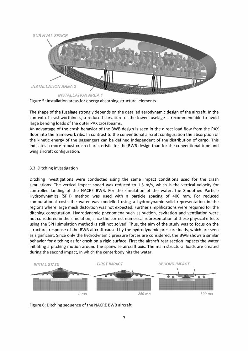
Figure 5: Installation areas for energy absorbing structural elements The shape of the fuselage strongly depends on the detailed aerodynamic design of the aircraft. In the context of crashworthiness, a reduced curvature of the lower fuselage is recommendable to avoid large bending loads of the outer PAX crossbeams. An advantage of the crash behavior of the BWB design is seen in the direct load flow from the PAX floor into the framework ribs. In contrast to the conventional aircraft configuration the absorption of the kinetic energy of the passengers can be defined independent of the distribution of cargo. This indicates a more robust crash characteristic for the BWB design than for the conventional tube and wing aircraft configuration. 3.3. Ditching investigation Ditching investigations were conducted using the same impact conditions used for the crash simulations. The vertical impact speed was reduced to 1.5 m/s, which is the vertical velocity for controlled landing of the NACRE BWB. For the simulation of the water, the Smoothed Particle Hydrodynamics (SPH) method was used with a particle spacing of 400 mm. For reduced computational costs the water was modelled using a hydrodynamic solid representation in the regions where large mesh distortion was not expected. Further simplifications were required for the ditching computation. Hydrodynamic phenomena such as suction, cavitation and ventilation were not considered in the simulation, since the correct numerical representation of these physical effects using the SPH simulation method is still not solved. Thus, the aim of the study was to focus on the structural response of the BWB aircraft caused by the hydrodynamic pressure loads, which are seen as significant. Since only the hydrodynamic pressure forces are considered, the BWB shows a similar behavior for ditching as for crash on a rigid surface. First the aircraft rear section impacts the water initiating a pitching motion around the spanwise aircraft axis. The main structural loads are created during the second impact, in which the centerbody hits the water.
Figure 6: Ditching sequence of the NACRE BWB aircraft

8
3.3. Derived design principles for enhanced ditching behavior For the identification of critical regions where water ingress and subsequent sinking could cause danger to the passengers, a strain based elimination criterion was applied. A strain threshold of 16 % was defined for element elimination for all aluminum parts. A contour plot of the damaged BWB aircraft is shown in Figure 7. Three regions, in which the hydrodynamic pressure forces can cause structural damage to the BWB aircraft, can be identified. In contrast to the crash simulation on solid ground high structural loads are obtained in the rear section of the aircraft during the first impact. Despite a failure of this region the structural fracture is outside of the protecting pressure vessel of the BWB. Thus, as long as the failure does not progress into the pressurized region, structural damage to the rear section can be seen as noncritical. Furthermore the main landing gear doors are damaged. A failure of the structurally weak but large main landing gear bay doors is not seen as direct hazard for the passengers as long as the protecting pressure vessel of the BWB remains intact. However, a central position of the landing gear bay is recommended. More consideration should be put in the intersection of the stiff landing gear bay and the adjacent soft fuselage section, which could cause structural damage to the pressure vessel. A third area of structural damage is seen directly along the centerline of the BWB aircraft. Whilst direct design modifications for the rear section and main landing gear are not necessary, a skin failure of the lower fuselage panel has to be seen as critical. Large ruptures of the skin between main landing gear bay and cockpit are a significant risk of producing fatalities due to rapid water ingress and subsequent sinking of the aircraft. Due to the flat shape of the BWB fuselage the water beneath the center of the impacting fuselage is constrained and only a small fraction of water close to the edge of the fuselage is able to flow around the flattened fuselage. Since water can be assumed to be incompressible under the given loading conditions, the vertical impact energy has to be absorbed by the structural deformation of the center fuselage.
Figure 7: Fuselage areas with high water loads during ditching

9
Figure 8: Global fuselage deformation and structural response during ditching The deformation of the lower fuselage and the structural response are sketched schematically in Figure 8. The deformation pattern of the lower fuselage is defined by the specific design of the BWB centerbody. The stiff framework ribs, necessary for a pressurized flattened fuselage, play a significant role in the structural deformation of the body impacting on water. The structural deformation is mainly obtained between the crosswise shear webs, since the bending stiffness of the frames is significantly lower than the compression stiffness of the framework ribs. The fuselage region between the bays buckles into the fuselage until the pressure load is carried by tensile membrane stress of the skin. The deformation leads to structural loads in the region of the stiff central framework rib, which could cause failure of the skin. Therefore recommended design features regarding the ditching of the BWB concentrate on the prevention of panel failure. Following design recommendations could prevent a fatal panel failure:
The joints between framework ribs and skin have to be designed to withstand load concentrations expected during ditching. This enhanced connection design should at least be applied to the framework ribs in or close to the centerline.
The thickness of the lower skin should be designed to withstand the expected high membrane stresses during ditching. Especially the skin close to the crosswise shear webs has to be stiffened to withstand the expected stress concentration peaks due to the stiff framework ribs. Increasing the thickness of the lower fuselage skin has the additional advantage that impact resistance against runway‐ or tire debris and other foreign objects is also improved. However, an increased skin thickness results in a considerable mass penalty.
Splices along the lower fuselage panel should be avoided as far as possible, since riveted joints could reduce the failure loads of the skin. By avoiding any longitudinal and transverse splices close to the centerline, a catastrophic joint failure in this region can be prevented. Hence large skin panels are recommended covering large areas close to the BWB centerline.
For the cargo doors, which are assumed to be located in the lower fuselage, high pressure forces during ditching have to be expected. A catastrophic failure of the cargo door could lead to significant water ingress and therefore a reduction of flotation time. By locating the cargo doors away from the central to the outer bays impact forces on the cargo door could be reduced.
10
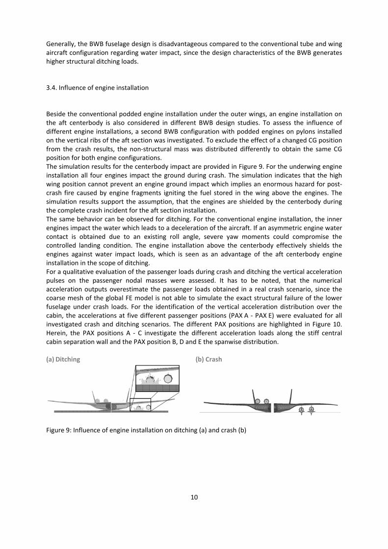
Generally, the BWB fuselage design is disadvantageous compared to the conventional tube and wing aircraft configuration regarding water impact, since the design characteristics of the BWB generates higher structural ditching loads. 3.4. Influence of engine installation Beside the conventional podded engine installation under the outer wings, an engine installation on the aft centerbody is also considered in different BWB design studies. To assess the influence of different engine installations, a second BWB configuration with podded engines on pylons installed on the vertical ribs of the aft section was investigated. To exclude the effect of a changed CG position from the crash results, the non‐structural mass was distributed differently to obtain the same CG position for both engine configurations. The simulation results for the centerbody impact are provided in Figure 9. For the underwing engine installation all four engines impact the ground during crash. The simulation indicates that the high wing position cannot prevent an engine ground impact which implies an enormous hazard for post‐crash fire caused by engine fragments igniting the fuel stored in the wing above the engines. The simulation results support the assumption, that the engines are shielded by the centerbody during the complete crash incident for the aft section installation. The same behavior can be observed for ditching. For the conventional engine installation, the inner engines impact the water which leads to a deceleration of the aircraft. If an asymmetric engine water contact is obtained due to an existing roll angle, severe yaw moments could compromise the controlled landing condition. The engine installation above the centerbody effectively shields the engines against water impact loads, which is seen as an advantage of the aft centerbody engine installation in the scope of ditching. For a qualitative evaluation of the passenger loads during crash and ditching the vertical acceleration pulses on the passenger nodal masses were assessed. It has to be noted, that the numerical acceleration outputs overestimate the passenger loads obtained in a real crash scenario, since the coarse mesh of the global FE model is not able to simulate the exact structural failure of the lower fuselage under crash loads. For the identification of the vertical acceleration distribution over the cabin, the accelerations at five different passenger positions (PAX A ‐ PAX E) were evaluated for all investigated crash and ditching scenarios. The different PAX positions are highlighted in Figure 10. Herein, the PAX positions A ‐ C investigate the different acceleration loads along the stiff central cabin separation wall and the PAX position B, D and E the spanwise distribution. (a) Ditching (b) Crash
Figure 9: Influence of engine installation on ditching (a) and crash (b)

11
Figure 10: Qualitative comparison of the vertical acceleration loads for discrete passenger positions For the assessment of the injury risks on the different PAX positions, the severity of the vertical acceleration pulses was analyzed using the Eiband diagram [6]. In Figure 10 the Eiband diagram is shown in which the grade of injury can be assessed according to the duration and the g‐force an occupant is exposed to. The resulting g‐force output with a duration of 10 ms was identified to be an effective way to compare the severity of the different vertical acceleration pulses. The results for the different PAX positions and the different crash and ditching scenarios are summarized in Figure 10. The following recommendations can be derived from the passenger acceleration outputs:
For the conventional engine installation, the highest acceleration loads are obtained in the front of the BWB aircraft. This increase can be explained by the crash kinematics of the aircraft, in which the pitch down motion is stopped abruptly when the front of the aircraft impacts the ground. This indicates that the application of energy absorbing structural elements is particularly required in the front of the aircraft.
The severity of the acceleration pulses declines for the outer bays. Therefore a structural design in the scope of crashworthiness and ditching is especially important for the central bays.
Despite the significantly lower vertical impact velocity during ditching, the simulation identifies high acceleration loads for ditching, especially at the front of the aircraft. The reason is assumed in the disadvantageous flattened BWB fuselage design regarding water impact.
The comparison of the vertical acceleration pulses indicates an engine installation on the aft section of the centerbody as favorable. Despite the same CG aircraft position, the change in
12
the engine position leads to a considerable reduction of the passenger loads on almost all investigated passenger positions. Since the largest reduction is obtained for the front seats of the aircraft, the main reason is assumed in a changed crash kinematics. The kinetic energy of the concentrated engine masses, positioned on the aft section of the aircraft, is mainly absorbed by the structural deformation of the unpressurized aft section of the BWB fuselage which subsequently leads to a reduction of the pitch down motion around the spanwise aircraft axis. For the investigated BWB fuselage shape, this reduction led to an extended ground contact of the aircraft during the crash event and subsequently to a diminished severity of the main impact.
5. Conclusions In the presented study, the crashworthiness and the ditching characteristics of a blended wing body aircraft were analyzed numerically on a global level. A statically sized FE model of the NACRE blended wing body aircraft was modified by including crash related structural components as hard‐sections, passengers and cargo floor. Crash simulations were performed that identified the framework ribs as the most promising structural component which could be used for controlled energy absorption during crash incidents. Since the crash kinematics of the blended wing body configuration shows reduced dependence on the state of cargo loading, the blended wing body aircraft design provides a more robust crash behavior than the conventional tube and wing aircraft design. The ditching studies indicate high pressure loads on the lower centerbody. A design of the centerbody, which prevents large fractures of the lower skin during water impact, is recommended. Furthermore, the investigation suggests that an engine installation on the aft section of the centerbody would be favorable in the scope of passenger injury risks during emergency landings. Additionally the simulations indicate that by using an aft engine installation, the engines are effectively shielded from crash related fragments during the complete crash and ditching event. Since the structural sizing of the used BWB configuration has a preliminary maturity status further investigations are required to confirm the derived findings. Acknowledgements
The research leading to these results has received funding from the EU commission within the project NACRE (Framework 6 IP AIP4‐CT‐2005‐516068)
[1] Bradley K., A Sizing Methodology for the conceptual Design of Blended‐Wing‐Body Transport, NASA/CR‐2004‐213016, 2004
[2] Bolsunovsky A.L., Buzoverya N.P., Gurevich B.I., Densisov V.E. et al., Flying Wing Problems and Decisions, Aircraft Design 4, 2001
[3] Cho S., Bil C. and Bayandor J., Structural Design and Analysis of a BWB Military Cargo Transport Fuselage, 46th AIAA Aerospace Sciences Meeting and Exhibit, 2008
[4] Department of Transport UK, White Paper, The Future of Air Transport, 2003
[5] Dmitirev V.G., Shkadov L.M., Denisiov V.D., Gurevich B.I. et al., Flying‐wing concept ‐ Changes and Risks, AIAA 2003‐2887, 2003
13
[6] Eiband, A.M., Human Tolerance to Rapidly Applied Accelerations: A Summary of the Literature, NASA Memorandum MEMO 5‐19‐59E, 1959
[7] FAR, 72 FR 54531 ‐ Special Conditions: Boeing Model 787‐8 Airplane; Crashworthiness, Federal Register Volume 72, Issue 186, 2007
[8] Federal Aviation Regulations, Part 25 – Airworthiness Standards: Transport Category Airplanes, FAA.gov, Federal Aviation Administration (FAA), 2015
[9] Hansen L., Heinze W. and Horst P., Blended Wing Body Structures in Multidisciplinary Pre‐Design, Journal of Structural and Multidisciplinary Optimization, Vol.36, 2008
[10] Liebeck R.H., Design of the Blended‐Wing‐Body Subsonic Transport, Journal of Aircraft, Vol.41, 2004
[11] Mukhopadhyay V., Sobieszczanski‐Sobieski J., Kosaka I., Quinn G. et al., Analysis Design and Optimization of Non‐cylindrical Fuselage for Blended‐Wing‐Body (BWB) Vehicle, 9th AIAA/ISSMO Symposium on Multidisciplinary Analysis and Optimization, 2002
[12] Mukhopadhyay V., Blended‐Wing‐Body (BWB) Fuselage Structural Design for Weight Reduction, 46th AIAA/ASME/ASCE/AHS/ASC Structures Dynamics and Material Conference, 2005
[13] Paluch B., Flying Wing 3D FEM, NACRE deliverable report, ONERA, 2007
[14] Schwinn D., Integration of Crashworthiness Aspects into Preliminary Aircraft Design, Applied Mechanics and Materials Vol. 598 pp 146‐150, 2014
[15] Wood R.M. and Bauer S., Flying Wings / Flying Fuselages, AIAA 2001‐0311, NASA Langley Research Center, 2001
[16] Wood R.M., The Contributions of Vincent Justus Burnelli, AIAA 2003‐0292, NASA Langley Research Center, 2003
Keywords: crash, explicit simulation, ditching, blended wing body, flying wing, energy
absorption