
CRANE MODEL: 8000 OPERATION AND …1).pdfANSI - ASME B30.5 - 1982 MOBILE AND LOCOMOTIVE CRANES The...
49
www.servicetrucks.com STI610392 6/23/04 $15 CRANE MODEL: 8000 OPERATION AND MAINTENANCE MANUAL A Division of Sioux Automation Center Inc. Q UALITY-PERFORMANCE-RELIABILITY TRUCKS SERVICE INTERNATIONAL A merica's Premier Manufacturer of Service Equipment 877 1st AVE. NW Sioux Center, IA 51250 Toll Free: 1-866-225-8789 Phone: 1-712-722-3711 View thousands of Crane Specifications on FreeCraneSpecs.com View thousands of Crane Specifications on FreeCraneSpecs.com
Transcript of CRANE MODEL: 8000 OPERATION AND …1).pdfANSI - ASME B30.5 - 1982 MOBILE AND LOCOMOTIVE CRANES The...
www.servicetrucks.com STI610392 6/23/04 $15
CRANE MODEL: 8000
OPERATION AND MAINTENANCE MANUAL
A Division of Sioux Automation Center Inc.
QUALITY-PERFORMANCE-RELIABILITY
TRUCKSSERVICE
INTERNATIONAL
America's Premier Manufacturer ofService Equipment
877 1st AVE. NW Sioux Center, IA 51250 Toll Free: 1-866-225-8789 Phone: 1-712-722-3711
View thousands of Crane Specifications on FreeCraneSpecs.comView thousands of Crane Specifications on FreeCraneSpecs.com

View thousands of Crane Specifications on FreeCraneSpecs.comView thousands of Crane Specifications on FreeCraneSpecs.com

TAKE NOTE! THIS SAFETY ALERT SYMBOL FOUND THROUGHOUT THIS MANUAL IS USED TO CALL YOUR ATTENTION TO INSTRUCTIONS INVOLVING YOUR PERSONAL SAFETY AND THE SAFETY OF OTHERS. FAILURE TO FOLLOW THESE INSTRUCTIONS CAN RESULT IN INJURY OR DEATH.
THIS SYMBOL MEANS
- ATTENTION! - BECOME ALERT!
- YOUR SAFETY IS INVOLVED! SIGNAL WORDS:
Note the use of the signal words DANGER, WARNING and CAUTION with the safety messages. The appropriate Signal word for each has been selected using the following guidelines: DANGER: Indicates an imminently hazardous situation that, if not avoided, will result in death or serious injury. This signal word is limited to the most extreme situations typically for machine components that cannot be guarded for functional purposes.
WARNING: Indicates a potentially hazardous situation that, if not avoided, could result in death or serious injury, and includes hazards that are exposed when guards are removed. It may also be used to alert against unsafe practices. CAUTION: Indicates a potentially hazardous situation that, if not avoided, may result in minor or moderate injury. It may also be used to alert against unsafe practices.
If you have any questions not answered in this manual or require additional copies or the manual is damaged, please contact your dealer or Sioux Automation Center, Inc., 877 1st Avenue N.W., Sioux Center, IA, 51250. (Telephone) 712-722-3711, (Fax) 712-722-3706.
View thousands of Crane Specifications on FreeCraneSpecs.comView thousands of Crane Specifications on FreeCraneSpecs.com

View thousands of Crane Specifications on FreeCraneSpecs.comView thousands of Crane Specifications on FreeCraneSpecs.com

I
INTRODUCTION
READ CAREFULLY
This manual is provided to familiarize you with the operation of your S.T.I. truck mounted 8000 hydraulic service crane and to supply you with the information necessary for proper equipment maintenance. It is the user's responsibility to maintain and operate this crane in a manner that will result in the safest working conditions possible. In addition, it is also the user's responsibility to be aware of existing Federal, State and Local codes and regulations governing the safe use and maintenance of this unit. Listed below is a publication that the user should read and understand.
ANSI - ASME B30.5 - 1982
MOBILE AND LOCOMOTIVE CRANES The American Society of Mechanical Engineers
United Engineering Center 345 East 47th Street
New York, NY 10017 Warranty of this unit will be void on any part of the unit subject to misuse due to overloading, abuse, lack of maintenance or unauthorized modifications. No warranty - verbal, written or implied - other than the official published S.T.I. new machinery and equipment warranty will be valid with this unit.
Treat the equipment with respect and service it regularly. These two things can add up to a safer working environment
and longer equipment life.
View thousands of Crane Specifications on FreeCraneSpecs.comView thousands of Crane Specifications on FreeCraneSpecs.com

II
TABLE OF CONTENTS
INTRODUCTION PAGE Section 1 Installation .......................................................... 1 - 2 Section 2 OPERATION...................................................... 3 - 6 2.1 General................................................................ 3 2.2 Load Limits......................................................... 3 2.3 Equipment Inspection ......................................... 3 2.4 Operating Restriction.......................................... 4 2.5 Load Lifting ........................................................ 5 2.6 Speed Control Operation .................................... 5 2.7 Task Performance ............................................... 5 2.8 Shutdown ............................................................ 5-6 Section 3 MAINTENANCE ............................................... 6 - 9 3.1 General................................................................ 6 3.2 Lubrication.......................................................... 6 3.3 Hydraulic Fluid Specification............................. 6-7 3.4 Hydraulic Oil Deterioration ................................ 7 3.5 Purging Air from the System .............................. 7-8 3.6 System Relief Pressure ....................................... 8 3.7 Remote Control Maintenance ............................. 8 3.8 Rotation Gear...................................................... 8 3.9 Worm Gear Adjustment...................................... 8 Section 4 TROUBLE-SHOOTING GUIDE....................... 9 APPENDIX:
Note: Read the entire manual before installing or operating crane
View thousands of Crane Specifications on FreeCraneSpecs.comView thousands of Crane Specifications on FreeCraneSpecs.com

1
SECTION 1 - INSTALLATION These instructions are intended as a guide to assist you with your particular installation. We cannot cover every make, model and year of truck manufactured worldwide, so these instructions will provide only general information. 1. Inspect the carrier vehicle to make certain it complies with the minimum chassis requirements indicated for this model of service crane. 2. Be certain that any modifications made to stiffen or reinforce the truck body have
been done according to the instructions of the body manufacturer. 3. Never weld, modify, or use unauthorized components on any S.T.I. units. This will void any warranty or liability and may result in a failure of the crane. 4. Install the boom cradle on the truck 5. Lift the crane to a height which is sufficient to allow for positioning the truck body underneath it. Mounting bolts, or bolt holes, should be in position to receive or line up with the bolt hole pattern on the base plate of the crane. 6. With the boom pointing toward the front of the truck, lower the crane into place and tighten the bolt nuts to the proper torque. Make sure the boom is resting properly in its support. 7. Connect the hydraulic pump to the crane. Two hydraulic fittings are located inside the
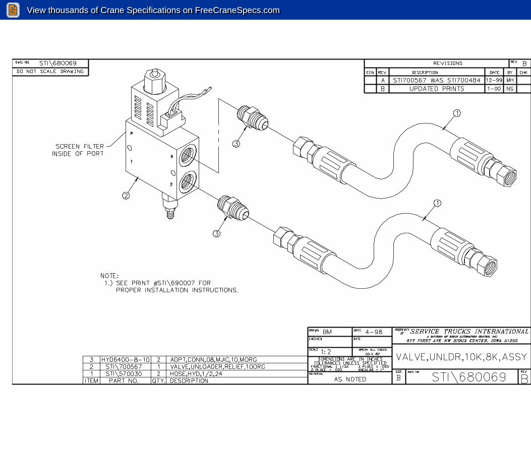
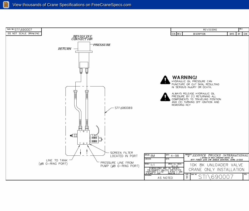
crane base and are accessible from the underside of the base plate. The pressure fitting is color coded with blue dykem. The pressure relief valve must be installed across the pressure and return lines and should be located in an accessible position. Recommended PSI operating ranges between crack pressure and full flow are as follows:
8000 2450 - 2650 PSI
NOTE: It is recommended that both the pressure and return lines on the 8000 be no less that ¾”. Do Not use hose on the hydraulic system of less than 100R1 rating. 8. The four strand power cord on the 8000 hydraulic provides power to the remote controller receptacle on the crane base and is accessible from the underside of the base plate. The four-strand power cord contains four wires and should be connected as shown in the wiring diagram included in the appendix of this manual.
View thousands of Crane Specifications on FreeCraneSpecs.comView thousands of Crane Specifications on FreeCraneSpecs.com

2
9. After the crane has been installed:
��Check all hydraulic lines for: ��Sharp corners (which may cut into hose) and kinks ��Abrasions and chafing ��Tightness of fittings ��Leaks
��Check all bolts and pins
��Visually inspect all welds for cracks, holes, etc.
��Engage Power Take-Off
��Slowly operate crane through all functions. Inspect all hoses, cylinders and structural members for proper operation.
��Return crane boom to its support and the unit is ready for operation.
10. If you wish to ensure that the pressure settings are correct to allow the crane to lift the proper loads within the recommended radius, utilize the following test procedure:
��Park the truck on solid, level ground
��Extend the outriggers
��Rotate the boom so that it is pointing out over the rear of the truck
��Position the boom at the 0 degree radius
��Extend the boom to maximum length
��Attach a test weight in the amount allowed for that unit , at 0 degrees, in a fully extended position
��Lift the weight using only the boom to the 45-degree position. Then rotate it
90 degrees in each direction to ensure free rotation, and eliminate any air pockets in the system
��If the boom will not pick the load, ensure that the boom is at the 0 degree
position, and the test weight is not more than the crane is rated for at that position
��After the test has been completed, return the boom to the normal transport
position
View thousands of Crane Specifications on FreeCraneSpecs.comView thousands of Crane Specifications on FreeCraneSpecs.com

3
SECTION 2 - OPERATION 2.1 GENERAL The crane is relatively simple to operate. However, prior to any work at job sites, the operator should thoroughly familiarize him or her self with the control operating procedures and practices for this unit. In addition, the operator should perform practice job operations before putting the unit to a task. The operator's understanding of emergency measure execution is essential; he or she should be prepared to take emergency control at any time. 2.2 LOAD LIMITS The crane is designed to provide excellent service if operated within maximum allowable load specifications stated on the unit's Angle Indicator Plate attached to both sides of the boom. The plate should be studied before lifting operation are started. Exceeding the stated load limit for a given radius of operation can cause tipping or structural failure and void the warranty. 2.3 EQUIPMENT INSPECTION Before operating the unit, always perform the safety checks outlined in this section. These procedures are vital to the detection of equipment malfunctions, which may be potential safety hazards. A. Structural Soundness
��Inspect the unit for damaged members and loose nut or bolts B. Hydraulic Oil Supply
��With the crane in a stored position, and all cylinders retracted, check the oil level C. Leakage
��Examine all of the visible hydraulic lines for frays and blisters. Look for signs of lubricating or hydraulic oil leakage
D. Controls
��Make a short test for proper control operation
E. Inspect for damaged, kinked or frayed winch cable F. Repairs
��Correct all observed defects and malfunctions before putting the unit into service
View thousands of Crane Specifications on FreeCraneSpecs.comView thousands of Crane Specifications on FreeCraneSpecs.com

4
2.4 OPERATING RESTRICTIONS Listed below are important points to remember while operating the unit. A. Keep the vehicle as level as possible while loading or unloading B. ALWAYS set the vehicle emergency brake before beginning crane operations C. ALWAYS use outriggers from vehicle to the ground during crane operations. Ensure
they are positioned on solid footings. D. ALWAYS depress the clutch pedal before engaging or disengaging the PTO E. ALWAYS extend the winch cable before extending the boom. F. ALWAYS keep the load as close to the ground as possible G. NEVER swing a load so that it passes over people H. NEVER rotate the crane too fast with a load I. NEVER operate the crane if in any position it will be within ten feet of a power line J. NEVER exceed the rated lifting capacities. Deduct the weight of any load handling
equipment from the rated capacity. K. NEVER leave a load suspended in the air L. NEVER use the winch to drag a load into position before lifting M. NEVER side load the boom by dragging a load from the side N. NEVER use the crane for lifting people O. NEVER operate the crane during an electrical storm or in high wind conditions P. NEVER attempt to service or repair the crane while the crane is operating Q. NEVER CONTINUE TO ROTATE CRANE IN ONLY ONE DIRECTION. The direction of rotation must be alternated to avoid damage to wire harness assembly
View thousands of Crane Specifications on FreeCraneSpecs.comView thousands of Crane Specifications on FreeCraneSpecs.com

5
2.5 LOAD LIFTING
It must be understood that all load ratings are formulated on 85% of tipping. Tipping is defined as a tire bearing contact with the ground. All load ratings are dependent upon compliance with the following:
A. The crane has been correctly installed on a truck in accordance with the chassis requirements and truck body manufacturers specifications are reinforcement
B. The intended operation is to be carried out on level, solid footing with proper outrigger placement
2.6 SPEED CONTROL OPERATION
The boom lift cylinder and rotation drive unit are both equipped with manual adjustable speed controls. The lift cylinder speed is controlled by needle valves located on the lift cylinder and the rotation drive speed is set at the factory to provide one half (1/2) revolution per minute.
2.7 TASK PERFORMANCE
To operate the crane:
A. Position the crane as close to the job as possible on a firm, dry and level surface. Avoid overhead obstruction on the work side of the unit
B. Set the parking brake
C. Shift the transmission into neutral and engage the PTO
D. Extend and lower the outriggers until firm ground contact is made. On soft ground, use bearing pads to prevent sinking
E. Before extending the boom, always pay out the winch cable. Failure to do so may result in damaging the cable and cable failure
S.T.I. cranes are equipped with counter balance valves inside of the lift cylinder. This valve functions as a deceleration control and serves as a safety device locking the load in case of a hydraulic line breakage or in the event of accidental or unauthorized operation of the directional valve when the pump is not operating.
The valve is equipped with a manual load release, which is to be used only in case of an emergency.
2.8 SHUTDOWN
A. Retract the boom and cable, making sure cable is properly wrapped on winch spool
B. Place the crane in a travel position
View thousands of Crane Specifications on FreeCraneSpecs.comView thousands of Crane Specifications on FreeCraneSpecs.com

6
C. Secure the hook
D. Stow the outriggers
E. Disengage the PTO
SECTION 3 - MAINTENANCE
3.1 GENERAL
A proper maintenance schedule, performed on a regular basis is essential in keeping the crane operating safely at peak efficiency
3.2 LUBRICATION
The intervals for all lubrications are weekly. However, maintaining the proper lubrication schedule will vary with climatic conditions and the amount of usage the unit receives. Periods of heavy use would shorten service intervals. See lubrication points and recommended lubricants.
3.3 HYDRAULIC FLUID SPECIFICATION
Minimum viscosity specifications for hydraulic oil to be used in the crane should be MOBIL DTE13M or equivalent to eliminate the necessity of seasonal oil changes under normal temperature conditions. For operations in extremely cold temperature, use a hydraulic fluid having a viscosity of 3000 SSU's at the lowest temperature encountered. Operating temperature of the hydraulic fluid should be within the range of 120 degrees to 160 degrees F(49 degrees C to 82 degrees C).
View thousands of Crane Specifications on FreeCraneSpecs.comView thousands of Crane Specifications on FreeCraneSpecs.com
7
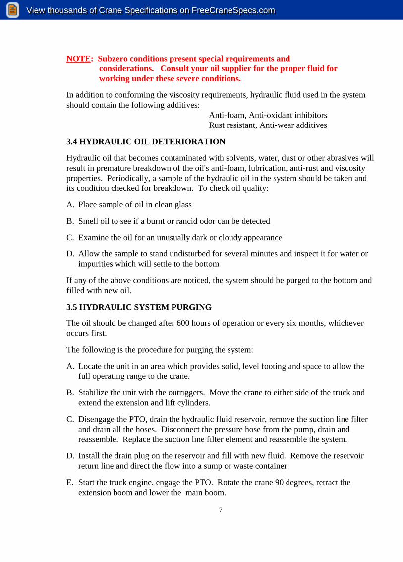
NOTE: Subzero conditions present special requirements and considerations. Consult your oil supplier for the proper fluid for working under these severe conditions.
In addition to conforming the viscosity requirements, hydraulic fluid used in the system should contain the following additives: Anti-foam, Anti-oxidant inhibitors Rust resistant, Anti-wear additives
3.4 HYDRAULIC OIL DETERIORATION
Hydraulic oil that becomes contaminated with solvents, water, dust or other abrasives will result in premature breakdown of the oil's anti-foam, lubrication, anti-rust and viscosity properties. Periodically, a sample of the hydraulic oil in the system should be taken and its condition checked for breakdown. To check oil quality:
A. Place sample of oil in clean glass
B. Smell oil to see if a burnt or rancid odor can be detected
C. Examine the oil for an unusually dark or cloudy appearance
D. Allow the sample to stand undisturbed for several minutes and inspect it for water or impurities which will settle to the bottom
If any of the above conditions are noticed, the system should be purged to the bottom and filled with new oil.
3.5 HYDRAULIC SYSTEM PURGING
The oil should be changed after 600 hours of operation or every six months, whichever occurs first.
The following is the procedure for purging the system:
A. Locate the unit in an area which provides solid, level footing and space to allow the full operating range to the crane.
B. Stabilize the unit with the outriggers. Move the crane to either side of the truck and extend the extension and lift cylinders.
C. Disengage the PTO, drain the hydraulic fluid reservoir, remove the suction line filter and drain all the hoses. Disconnect the pressure hose from the pump, drain and reassemble. Replace the suction line filter element and reassemble the system.
D. Install the drain plug on the reservoir and fill with new fluid. Remove the reservoir return line and direct the flow into a sump or waste container.
E. Start the truck engine, engage the PTO. Rotate the crane 90 degrees, retract the extension boom and lower the main boom.
View thousands of Crane Specifications on FreeCraneSpecs.comView thousands of Crane Specifications on FreeCraneSpecs.com

8
F. The system is now purged. Replace the return line filter cartridge and reinstall the return line to the reservoir.
G. Examine the reservoir fluid level and add fluid to the “FULL” mark.
3.6 PURGING AIR FROM THE SYSTEM
If air is trapped in the cylinder, it will cause an erratic “bumpy” condition. To remove the air, hold the affected control open after the function has “bottomed out”. Move the function in the opposite direction and again hold the control open. Operate the crane in a normal manner to determine if the air has been purged. If not, repeat procedure.
3.7 SYSTEM RELIEF PRESSURE
If you wish to ensure that the relief pressure setting is correct, it will be necessary to install a pressure gauge in the 1/4" NPT near the front top side of valve manifold. The test can be performed by utilizing either the boom cylinder or the extend cylinder. Fully retract either cylinder and hold in while observing pressure reading on gauge.
A. Start the truck engine, engage the PTO and allow the system to idle until it reaches operating temperature
B. Raise the boom until the cylinder is fully extended. Continue to hold the valve open and read the pressure on a pressure gauge. A reading of less than normal should be corrected by increasing the pressure.
If the pressure reading is too high or too low, it will be necessary to adjust the relief valve set screw.
Adjustments are made by unlocking the jam nut and turning set screw clockwise to increase pressure and counter clockwise to decrease pressure.
Recommended PSI ranges between crack pressure and full flow should be 2450-2550 PSI
3.8 REMOTE CONTROL MAINTENANCE
The remote control is subject to corrosion and must be checked at least twice a year and more often if operated in sever, wet conditions. To check for corrosion: A. Remove the cover plate and inspect for a lack of luster. Metals should appear bright
and untarnished.
B. Spray the inside of the box with an ignition sealer such as Krylon.
3.9 ROTATION GEAR No adjustments are to be made to the 8000 Planetary Drive without prior consultation with the factory. The Planetary Drive is set at the factory and should require not adjustment.
View thousands of Crane Specifications on FreeCraneSpecs.comView thousands of Crane Specifications on FreeCraneSpecs.com
9
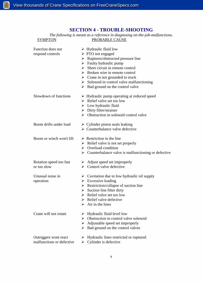
SECTION 4 - TROUBLE-SHOOTING The following is meant as a reference in diagnosing on-the-job-malfunctions.
SYMPTON PROBABLE CAUSE Function does not � Hydraulic fluid low respond controls � PTO not engaged
��Ruptures/obstructed pressure line ��Faulty hydraulic pump ��Short circuit in remote control ��Broken wire in remote control ��Crane in not grounded to truck ��Solenoid in control valve malfunctioning ��Bad ground on the control valve
Slowdown of functions � Hydraulic pump operating at reduced speed
��Relief valve set too low ��Low hydraulic fluid ��Dirty filter/strainer ��Obstruction in solenoid control valve
Boom drifts under load � Cylinder piston seals leaking � Counterbalance valve defective Boom or winch won't lift � Restriction in the line
��Relief valve is not set properly ��Overload condition ��Counterbalance valve is malfunctioning or defective
Rotation speed too fast � Adjust speed set improperly or too slow � Control valve defective Unusual noise in � Cavitation due to low hydraulic oil supply operation � Excessive loading
��Restriction/collapse of suction line ��Suction line filter dirty ��Relief valve set too low ��Relief valve defective ��Air in the lines
Crane will not rotate � Hydraulic fluid level low
��Obstruction in control valve solenoid ��Adjustable speed set improperly ��Bad ground on the control valves
Outriggers wont react � Hydraulic lines restricted or ruptured malfunctions or defective � Cylinder is defective
View thousands of Crane Specifications on FreeCraneSpecs.comView thousands of Crane Specifications on FreeCraneSpecs.com

View thousands of Crane Specifications on FreeCraneSpecs.comView thousands of Crane Specifications on FreeCraneSpecs.com

REVISIONS
2264 A ADDED ASTERISK CALLOUT 7-03 JGS
D
C
B
A
B
C
D
12345678
8 7 6 5 4 3 2 1
REV -DWG NO.
STI400086
DO NOT SCALE DRAWING
DRAWN
DATECHECKED
SCALE BREAK ALL EDGES.03 X 45
FRACTIONAL 1/32 3 PLACE .0052 PLACE .020 ANGULAR 1
DIMENSIONS ARE IN INCHESTOLERENCES UNLESS SPECIFIED
MATERIALREVDWG NO.SIZE
B
CASDATE
3-01
1:1
AS NOTED STI400086 -
DECAL,CHART,LOAD,8K
SHEET OF 11
D
C
B
A
B
C
D
12345678
8 7 6 5 4 3 2 1
REV -DWG NO.
STI400086
DO NOT SCALE DRAWING
DRAWN
DATECHECKED
SCALE BREAK ALL EDGES.03 X 45
FRACTIONAL 1/32 3 PLACE .0052 PLACE .020 ANGULAR 1
DIMENSIONS ARE IN INCHESTOLERENCES UNLESS SPECIFIED
MATERIALREVDWG NO.SIZE
B
CASDATE
3-01
1:1
AS NOTED STI400086 -
DECAL,CHART,LOAD,8K
SHEET OF 11
877 FIRST AVE NW SIOUX CENTER, IA 51250877 FIRST AVE NW SIOUX CENTER, IA 51250877 FIRST AVE NW SIOUX CENTER, IA 51250877 FIRST AVE NW SIOUX CENTER, IA 51250A DIVISION OF SIOUX AUTOMATION CENTER INC.A DIVISION OF SIOUX AUTOMATION CENTER INC.A DIVISION OF SIOUX AUTOMATION CENTER INC.A DIVISION OF SIOUX AUTOMATION CENTER INC.
PROPERTY OF: SERVICE TRUCKS INTERNATIONALSERVICE TRUCKS INTERNATIONALSERVICE TRUCKS INTERNATIONALSERVICE TRUCKS INTERNATIONAL
6.04
4.50
NOTE:
MATERIAL 5-8 YEAR CAST VINYLWITH PERMANENT PRESSURE SENSITIVEADHESIVE AND CLEAR UV COATINGOR EQUIVALENT
MODEL 8000
LOAD CAPACITIES
4000
4500*
MEASURED IN POUNDS
3500
3000
3500
4000
6000*
5000*
5000*
6000*
20
15
8000*
8000*
75°
60°
45°
(FT.)
HEIGHT
10
266030004360*
1611 18
5
5LC
DISTANCE (FT.)
* MAXIMIUM SINGLE LINE CAPACITY IS4000 LBS IN THESE OPERATING POSITIONS
30°
STI400086
View thousands of Crane Specifications on FreeCraneSpecs.comView thousands of Crane Specifications on FreeCraneSpecs.com

View thousands of Crane Specifications on FreeCraneSpecs.comView thousands of Crane Specifications on FreeCraneSpecs.com

View thousands of Crane Specifications on FreeCraneSpecs.comView thousands of Crane Specifications on FreeCraneSpecs.com

ITEM # QTY PART # DESCRIPTION1 1 STI680122 BASE,CRANE,8K2 1 STI680123 HOUSING,GEAR,ROTATE3 1 STI680131 TURRET,8K,WLD4 2 STI700043 PIN,DOWEL,METAL,.5,1.55 1 STI610339 MOUNT,DRIVE,ROTATE6 8 BLT58X212NCML BLT,HEX,5/8,2-1/2,NC,G87 1 PFBL18COU COUP,1/8,BLK8 1 PFBL18X212NIP NIPPLE,1/8,2-1/2,BLK9 9 SPDHB58X134NC BLT,SHCS,5/8,1-3/4,NC10 22 SPDHB58X312NC BLT,SHCS,5/8,3-1/2,NC11 15 SPDHB58X4NC BLT,SHCS,5/8,4,NC12 2 SPGZRK610 ZRK,GRS,1/8,MALE,PIPE,STR13 4 WSH58LOCK WSH,LOCK,5/814 4 SPDHB516X1 BLT,SHCS,5/16,1,NC15 4 WSH516LOCK WSH,LOCK,5/1616 1 STI680139 ROTATE,8K,ASSY17 1 STI680124 CONN,ROTATE,8K,10K,ASSY18 1 STI700000 RING,SLEWING,8K,MACHINED
REVISIONSECN REV. DESCRIPTION DATE BY CK
A BLT58X212NCML WAS BLT58X212NC 8-00 NS1635 B ADD OPTIONS & LEVEL INFO 4-02 CS1853 C DELETE OPTIONS & LEVEL INFO 9-02 AP3300 D SEE ECN #3300 FOR CHANGES 12-04 SZ
D
C
B
A
B
C
D
12345678
8 7 6 5 4 3 2 1REV DDWG NO. STI691802
DO NOT SCALE DRAWING
DRAWN
DATECHECKED
SCALE BREAK ALL EDGES.03 X 45
FRACTIONAL 1/32 3 PLACE .0052 PLACE .020 ANGULAR 1
DIMENSIONS ARE IN INCHESTOLERENCES UNLESS SPECIFIED
MATERIAL
PROPERTY OF SERVICE TRUCKS INTERNATIONAL877 FIRST AVE NW SIOUX CENTER, IA 51250
REVDWG NO.SIZE
B
RMPDATE
5-99
1:12
AS NOTED STI691802 DTURRET,8K,ASSY
SHEET OF 11
A DIVISION OF SIOUX AUTOMATION CENTER INC.
ISO VIEW AFTER ASSEMBLY
NOTE: ITEMS STI680139 AND STI680124 ARE INCLUDED IN THE BOM OF HYD PRINT #STI\691812
1 12
18
8
7
10
122
6
5
3
4
9
16
13
10
11
1715
14
View thousands of Crane Specifications on FreeCraneSpecs.comView thousands of Crane Specifications on FreeCraneSpecs.com

View thousands of Crane Specifications on FreeCraneSpecs.comView thousands of Crane Specifications on FreeCraneSpecs.com

View thousands of Crane Specifications on FreeCraneSpecs.comView thousands of Crane Specifications on FreeCraneSpecs.com

View thousands of Crane Specifications on FreeCraneSpecs.comView thousands of Crane Specifications on FreeCraneSpecs.com

3
4
10
14
142
5
61 12
15
NOTE:1) ITEM #12 ARE USED TO CONNECT CONTROL CABLE TO PUSH BUTTON AND ITEM #13 ARE USED TO CONNECT CONTROL CABLE TO TOGGLE SWITCHES.2) ITEM #15 ARE USED TO MAKE JUMPER WIRES INSIDE OF BOX.
8
7
9
13
REVISIONSECN REV. DESCRIPTION DATE BY CK
A STI1814CNTRL WAS STI1812CNTRL 6-99 HW988 B STI700291 QTY WAS 26 3-01 CAS
1556 C STI680057 WAS COMPONENTS 3-02 BPL1633 D SEE ECN FOR CHANGES 4-02 BJL
3618 E CHG: REVISED FUNCTION POSITIONS,STI700291 QTY WAS 23 6-05 SZ
ITEM # QTY PART # DESCRIPTION1 4 SPMB832X34SSP SCREW,MACH,8-32,3/4,SS2 1 STI100156 COVER,BOX,CNTRL,ELEC3 1 STI200109 BOX,CNTRL,ELEC4 1 STI680164 CORD,REMOTE,HYD,300",AMPHNL5 1 STI700140 DECAL,FACE,CNTRL,REMOTE,HYD6 5 STI700155 BOOT,RUBBER7 1 STI700176 DECAL,WARNING,CONT,ROTATE8 1 STI700188 GRIP,CORD,DELUXE,CNTRL,REMOTE9 1 STI700189 SWITCH,BUTTON,PUSH
10 1 STI700250 SWITCH,TOGGLE,2-WAY,SPADE11 2 STI700279 TRMNL,RING,INSLTD,STI,ALL12 26 STI700291 TRMNL,PUSHON,STI,ALL13 1 STI700346 BOOT,RUBBER14 4 STI700366 SWITCH,TOGGLE,MOM,DPDT,SPADE15 24 STIWIRE18PRBL WIRE,PRIMARY,18GA,BLK
1
D
C
B
A
B
C
D
12345678
8 7 6 5 4 3 2 1REV EDWG NO. STI680043
DO NOT SCALE DRAWING
DRAWN
DATECHECKED
SCALE
2
.03 X 45BREAK ALL EDGES
OFSHEET
REMOTE,HYD,25',AMPHNL,UNLDR
E 1 .020 ANGULAR
TOLERENCES UNLESS SPECIFIED
MATERIAL
PROPERTY OF SERVICE TRUCKS INTERNATIONAL877 FIRST AVE NW SIOUX CENTER, IA 51250
REVDWG NO.SIZE
B
BMDATE
11-97
1:4
AS NOTED STI680043FRACTIONAL 1/32 3 PLACE .0052 PLACE
DIMENSIONS ARE IN INCHES
A DIVISION OF SIOUX AUTOMATION CENTER INC.
View thousands of Crane Specifications on FreeCraneSpecs.comView thousands of Crane Specifications on FreeCraneSpecs.com

2-(A) RED
1-(B) BLK
8-(C) BLU/BLK STP
7-(D) RED/BLK STP
6-(E) BRN
3-(F) BLU
10(K) YEL/BLK STP
9-(J) ORG/BLK STP
5-(H) YEL
4-(G) ORG
14-ORG/RED STP - SPARE
13-BLUE/RED STP - SPARE
12(M) BLK/RED STP
11(L) BRN/BLK STP
9
1
2
7
8
3
6
5
4
NOTE:3) "ON" SIDE OF POWER TOGGLE IS +12V POWER SUPPLY TO ALL OTHER SWITCHES.4) PIN "M" IS ENERGIZED WHEN THE ROTATE, LIFT, WINCH, AND EXTEND SWITCHES ARE ACTIVATED IN EITHER DIRECTION.
1110
M M M M
M M M M
BACKSIDE VIEW
D
C
B
A
B
C
D
12345678
8 7 6 5 4 3 2 1REV EDWG NO. STI680043
DO NOT SCALE DRAWING
DRAWN
DATECHECKED
SCALE BREAK ALL EDGES.03 X 45
FRACTIONAL 1/32 3 PLACE .0052 PLACE .020 ANGULAR 1
DIMENSIONS ARE IN INCHESTOLERENCES UNLESS SPECIFIED
MATERIAL
PROPERTY OF SERVICE TRUCKS INTERNATIONAL877 FIRST AVE NW SIOUX CENTER, IA 51250
REVDWG NO.SIZE
B
BMDATE
11-97
1:1
AS NOTED STI680043 EREMOTE,HYD,25',AMPHNL,UNLDR
SHEET OF 22
A DIVISION OF SIOUX AUTOMATION CENTER INC
View thousands of Crane Specifications on FreeCraneSpecs.comView thousands of Crane Specifications on FreeCraneSpecs.com

View thousands of Crane Specifications on FreeCraneSpecs.comView thousands of Crane Specifications on FreeCraneSpecs.com

View thousands of Crane Specifications on FreeCraneSpecs.comView thousands of Crane Specifications on FreeCraneSpecs.com

View thousands of Crane Specifications on FreeCraneSpecs.comView thousands of Crane Specifications on FreeCraneSpecs.com

View thousands of Crane Specifications on FreeCraneSpecs.comView thousands of Crane Specifications on FreeCraneSpecs.com

View thousands of Crane Specifications on FreeCraneSpecs.comView thousands of Crane Specifications on FreeCraneSpecs.com

View thousands of Crane Specifications on FreeCraneSpecs.comView thousands of Crane Specifications on FreeCraneSpecs.com

View thousands of Crane Specifications on FreeCraneSpecs.comView thousands of Crane Specifications on FreeCraneSpecs.com

View thousands of Crane Specifications on FreeCraneSpecs.comView thousands of Crane Specifications on FreeCraneSpecs.com
View thousands of Crane Specifications on FreeCraneSpecs.comView thousands of Crane Specifications on FreeCraneSpecs.com

View thousands of Crane Specifications on FreeCraneSpecs.comView thousands of Crane Specifications on FreeCraneSpecs.com

View thousands of Crane Specifications on FreeCraneSpecs.comView thousands of Crane Specifications on FreeCraneSpecs.com

View thousands of Crane Specifications on FreeCraneSpecs.comView thousands of Crane Specifications on FreeCraneSpecs.com

4
3
1
5
5
5
2
CHKBYDATEDESCRIPTIONREV.ECN
REVISIONS
ITEM # QTY. PART # DESCRIPTION1 1 SPORG113 ORG,3.125,3.38,#1132 1 SPOSRG3 RING,SNAP,OUTSIDE,33 1 STI610560 CONN,ROTATE,HYD,8K,10K4 1 STI610561 SLEEVE,CONN,HYD,8K,10K5 3 STI700048 SEAL,PARKER,334
SECTION A-A
5.00
2.00
1
D
C
B
A
B
C
D
12345678
8 7 6 5 4 3 2 1REV -DWG NO. STI600061
DO NOT SCALE DRAWING
DRAWN
DATECHECKED
SCALE
OFSHEETAS NOTED
.03 X 451:2 BREAK ALL EDGES
CONN,ROTATE,HYD,8K,10K,ASSY
4-06
-
DATE
STI600061
SZ
1
TOLERENCES UNLESS SPECIFIED
MATERIALREVDWG NO.SIZE
B
FRACTIONAL 1/32 3 PLACE .0052 PLACE .020 ANGULAR
DIMENSIONS ARE IN INCHES
1
PROPERTY OF:
877 FIRST AVE NW SIOUX CENTER, IA 51250A DIVISION OF SIOUX AUTOMATION CENTER INC.
SERVICE TRUCKS INTERNATIONAL
4.38
8.56
A
A
View thousands of Crane Specifications on FreeCraneSpecs.comView thousands of Crane Specifications on FreeCraneSpecs.com

View thousands of Crane Specifications on FreeCraneSpecs.comView thousands of Crane Specifications on FreeCraneSpecs.com

View thousands of Crane Specifications on FreeCraneSpecs.comView thousands of Crane Specifications on FreeCraneSpecs.com
View thousands of Crane Specifications on FreeCraneSpecs.comView thousands of Crane Specifications on FreeCraneSpecs.com
View thousands of Crane Specifications on FreeCraneSpecs.comView thousands of Crane Specifications on FreeCraneSpecs.com

View thousands of Crane Specifications on FreeCraneSpecs.comView thousands of Crane Specifications on FreeCraneSpecs.com

BJL000717NS
STI\700028-1
REFERENCE PARTS LIST FOR TULSA WINCH HFG938 L-041(80531) ITEM PART # DESCRIPTION QUANTITY 1 40643 OIL SEAL 1 PC 2 41314 BEARING 1 PC 3 4101 BREATHER KIT 1 PC 4 40640 HOUSING 1 PC 5 41006 SHAFT 1 PC 6 41005 KEY 1 PC 7 40518 KEY 2 PC 8 40644 WASHER 1 PC 9 40618 GEAR 1 PC 10 29017 WASHER 1 PC 11 40968 BUSHING 1 PC 12 40547 O-RING 1 PC 13 40893 COVER 1 PC 14 40918 WASHER 6 PC 15 40407 CAPSCREW 6 PC 16 40410 CAPSCREW 2 PC 17 33561 PROTECTOR 1 PC 18 40147 GASKET 2 PC 19 40396 RETAINING RING 2 PC 20 40395 BEARING 2 PC 21 40598 WORM 1 PC 22 32220 PIPE PLUG 2 PC 23 40599 SPACER 1 PC 24 40076 STATOR PLATE 2 PC 25 40075 FRICTION DISK 2 PC 26 40617 HUB 1 PC 27 40113 CAM CLUTCH 1 PC 28 40077 SPRING 1 PC 29 40078 WASHER 1 PC 30 40069 HOUSING 1 PC 31 40546 CAPSCREW 2 PC 32 29044 SEAL WASHER 1 PC 33 40774 LOCK NUT 1 PC 34 40775 SET SCREW 1 PC
View thousands of Crane Specifications on FreeCraneSpecs.comView thousands of Crane Specifications on FreeCraneSpecs.com
View thousands of Crane Specifications on FreeCraneSpecs.comView thousands of Crane Specifications on FreeCraneSpecs.com

View thousands of Crane Specifications on FreeCraneSpecs.comView thousands of Crane Specifications on FreeCraneSpecs.com

View thousands of Crane Specifications on FreeCraneSpecs.comView thousands of Crane Specifications on FreeCraneSpecs.com

View thousands of Crane Specifications on FreeCraneSpecs.comView thousands of Crane Specifications on FreeCraneSpecs.com

SERVICE TRUCKS INT'L TIGER CRANE WARRANTY
S.T.I. warrants to consumer, each new S.T.I./Tiger Crane sold by it to be free, under normal use and service, from defects in material and workmanship. Terms of warranty are: 3 YEARS - From date of sale to the Original Purchaser: base plate weldment, turret assembly and structural integrity of the crane boom assembly. 1 YEAR - From date of sale to the Original Purchaser: electrical & hydraulic components This warranty, as described above, is expressly limited to the repair, or at S.T.I.'S option, replacement of parts proven to S.T.I.'S satisfaction to be defective which are returned, F.O.B. customer location. All parts which are repaired or replaced under the terms of this warranty will be shipped, F.O.B. Destination, from S.T.I.'S factory in Sioux Center, IA. STI will pay standard freight expense of parts to and from the owner. Faster freight service is available, with the owner paying the difference between standard and preferred method of owner. Freight of whole goods to or from the factory is the owner’s expense, regardless if they fall under warranty or not. All warranty decisions will be final! This warranty does not cover the cost of labor, parts or transportation charges when any party other than S.T.I. performs the replacement or repair of parts claimed to be defective, nor shall this warranty apply to an S.T.I. product upon which any alterations or repairs other than normal maintenance have been made without the written approval of S.T.I. S.T.I. shall in no event be liable for consequential damages, lost profits or contingent liabilities arising out of the failure of any S.T.I. product or parts to operate properly. WARRANTY CARD MUST BE FILLED OUT AND RETURNED TO FACTORY IMMEDIATELY UPON RECEIPT OF EQUIPMENT TO INSURE WARRANTY COVERAGE. THIS WARRANTY IS EXTENDED ONLY TO THE INITIAL PURCHASER FROM AN AUTHORIZED S.T.I./TIGER CRANE DISTRIBUTOR AND MAY NOT BE REASSIGNED. THIS WARRANTY IS EXPRESSLY IN LIEU OF ANY OTHER WARRANTIES EXPRESSED OR IMPLIED, INCLUDING ANY IMPLIED WARRANTIES OF MERCHANTABILITY OR FOR A PARTICULAR PURPOSE AND S.T.I. NEITHER ASSUMES OR AUTHORIZES ANY OTHER PERSON TO ASSUME FOR IT ANY OTHER LIABILITY. THERE ARE NO WARRANTIES, WHICH EXTEND BEYOND THE DESCRIPTION OF THE FACE HEREOF. We reserve the right to make improvements to any of our products without notice or obligation regarding models previously sold. CRANE SERIAL # _________________________ Effective 08/01
View thousands of Crane Specifications on FreeCraneSpecs.comView thousands of Crane Specifications on FreeCraneSpecs.com


![[47th KUG PP] Visual Presentation](https://static.fdocuments.net/doc/165x107/55568e37d8b42a182f8b4da0/47th-kug-pp-visual-presentation.jpg)

