Cracks in Installed Reinforced Concrete Pipe · Reinforced concrete pipe, like other reinforced...
4
Concrete Pipe Information 0.01-Inch Crack Measured in a 36-Inch, Class IV Pipe. Pictures 1, 2, and 3 shown as if viewing the crack standing, kneeling, or through a video inspection, respectively. American Concrete Pipe Association • [email protected] • www.concretepipe.org “Some engineers insist that a crack in a concrete pipe in excess of 0.01-inch represents a failure or partial failure situation. Such a conclusion is utterly ridiculous and represents a disservice, not only to the concrete pipe industry, but taxpayers as well.” 1 This quote from Professor M.G. Spangler, a well respected author- ity and early pioneer in the design of concrete pipe, should be taken into consideration when designing, installing, inspecting, or funding a project using reinforced concrete pipe, (RCP). All parties involved should be aware of the insignifi- cance of a 0.01-inch crack. Reinforced concrete pipe, like other reinforced concrete structures, is designed to crack. It is well known that while concrete is very strong in compression, its tensile strength is so low that it is considered negligible in design. Therefore, RCP design accommodates the high compres- sive strength of concrete and the high tensile strength of steel. As load on the pipe increases, and the tensile strength of the concrete is exceeded, cracks will form as the tensile load is transferred to the steel. Typically, the cracks form a V-shape with the largest part of the crack at the surface. The presence of a 0.01-inch crack does not repre- sent failure, but rather an indication that the concrete and reinforcement are working together, as intended. The 0.01-inch crack criteria has been used as a service load design criteria for RCP for nearly 70 years. This criterion has served the industry well through the clear designation of a plant test protocol. It has also served the public well by conservatively ensuring that a strong and durable product is used in their buried infrastructure. The 0.01-inch crack was never intended to determine the failure of installed RCP. This crack width was established by Professor W.J. Schlick of Iowa State University to establish the comparative strength of RCP, in a three-edge-bearing test by using a simple 0.01-inch thick leaf gauge to determine a measurable and definitive size crack. The three- edge-bearing test is a plant test that applies a bearing strip along the top of the pipe, and two closely spaced bearing strips along the bottom. Specifications for RCP require an ultimate load resistance that ex- ceeds the required 0.01-inch crack strength, giving the designed pipe a significant factor of safety above the required service load. The 0.01- inch crack width has absolutely no relation to the size of a crack that Cracks in Installed Reinforced Concrete Pipe 1 2 3 Cracks may appear larger in video inspection
Transcript of Cracks in Installed Reinforced Concrete Pipe · Reinforced concrete pipe, like other reinforced...
Concrete Pipe Information
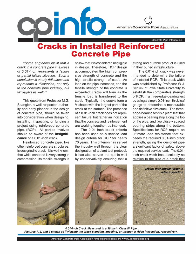
0.01-Inch Crack Measured in a 36-Inch, Class IV Pipe.Pictures 1, 2, and 3 shown as if viewing the crack standing, kneeling, or through a video inspection, respectively.
American Concrete Pipe Association • [email protected] • www.concretepipe.org
“Some engineers insist that a crack in a concrete pipe in excess of 0.01-inch represents a failure or partial failure situation. Such a conclusion is utterly ridiculous and represents a disservice, not only to the concrete pipe industry, but taxpayers as well.”1
This quote from Professor M.G. Spangler, a well respected author-ity and early pioneer in the design of concrete pipe, should be taken into consideration when designing, installing, inspecting, or funding a project using reinforced concrete pipe, (RCP). All parties involved should be aware of the insignifi -
cance of a 0.01-inch crack.Reinforced concrete pipe, like
other reinforced concrete structures, is designed to crack. It is well known that while concrete is very strong in compression, its tensile strength is
so low that it is considered negligible in design. Therefore, RCP design accommodates the high compres-sive strength of concrete and the high tensile strength of steel. As load on the pipe increases, and the tensile strength of the concrete is exceeded, cracks will form as the tensile load is transferred to the steel. Typically, the cracks form a V-shape with the largest part of the crack at the surface. The presence of a 0.01-inch crack does not repre-sent failure, but rather an indication that the concrete and reinforcement are working together, as intended.
The 0.01-inch crack criteria has been used as a service load design criteria for RCP for nearly 70 years. This criterion has served the industry well through the clear designation of a plant test protocol. It has also served the public well by conservatively ensuring that a
strong and durable product is used in their buried infrastructure.
The 0.01-inch crack was never intended to determine the failure of installed RCP. This crack width was established by Professor W.J. Schlick of Iowa State University to establish the comparative strength of RCP, in a three-edge-bearing test by using a simple 0.01-inch thick leaf gauge to determine a measurable and defi nitive size crack. The three-edge-bearing test is a plant test that applies a bearing strip along the top of the pipe, and two closely spaced bearing strips along the bottom. Specifi cations for RCP require an ultimate load resistance that ex-ceeds the required 0.01-inch crack strength, giving the designed pipe a signifi cant factor of safety above the required service load. The 0.01-inch crack width has absolutely no relation to the size of a crack that
Cracks in Installed Reinforced Concrete Pipe
1 2 3
Cracks may appear larger in
video inspection
CP Info crack 082707.indd 1 9/7/07 3:30:51 PM
Cracks may appear larger in
video inspection
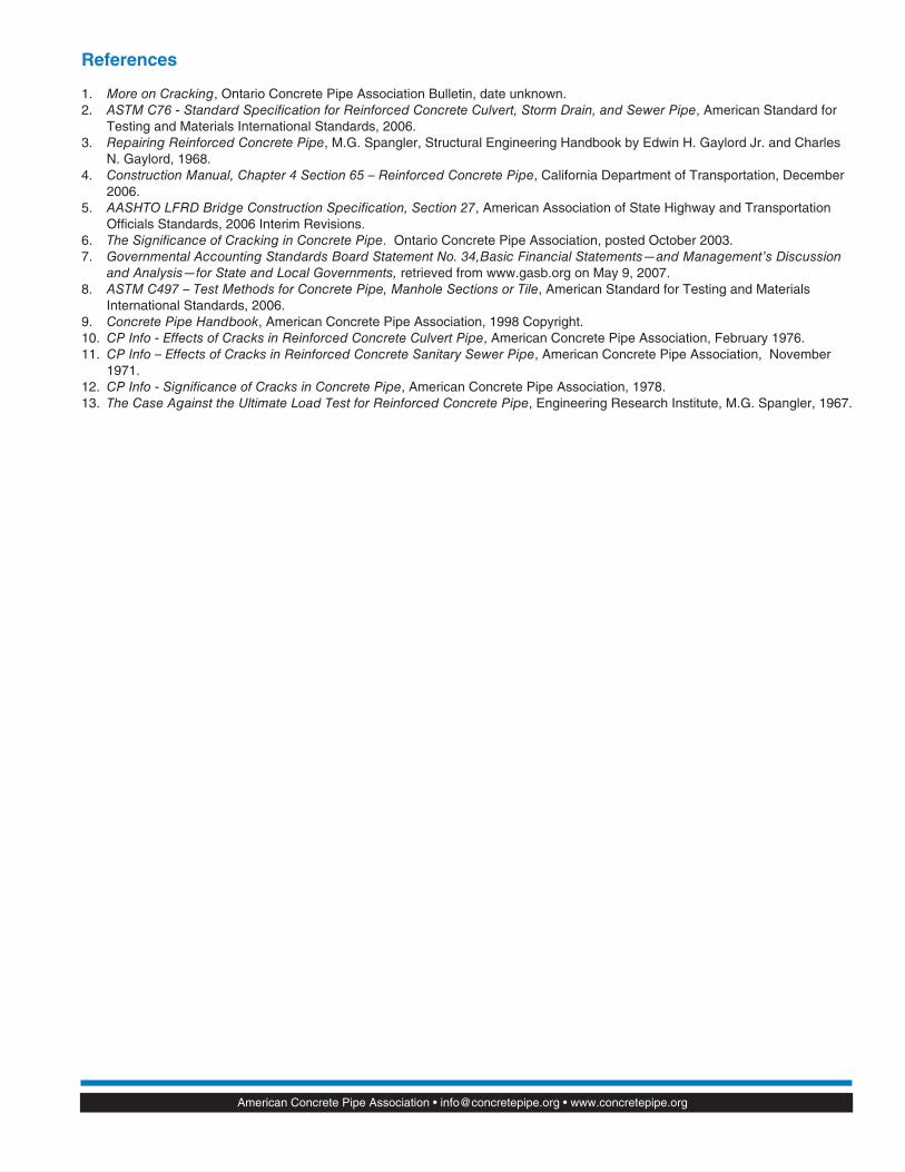
The 0.04-inch crack shown is less than half the crack width of 0.10-inch accepted by Caltrans4 and AASHTO5.
Pictures 1, 2, and 3 shown as if viewing the crack standing, kneeling, or through a video inspection, respectively.
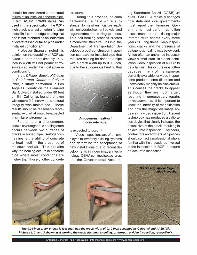
Autogenous healing in
concrete pipe.
American Concrete Pipe Association • [email protected] • www.concretepipe.org
should be considered a structural failure of an installed concrete pipe. In fact, ASTM C76-06 states, “As used in this specifi cation, the 0.01-inch crack is a test criterion for pipe tested in the three-edge-bearing test and is not intended as an indication of overstressed or failed pipe under installed conditions.”2
Professor Spangler noted his opinion on the durability of RCP as, “Cracks up to approximately 1/16-inch in width will not permit corro-sion except under the most adverse conditions”3.
In the CP Info - Effects of Cracks in Reinforced Concrete Culvert Pipe, a study performed in Los Angeles County on the Diamond Bar Culvert installed under 80 feet of fi ll in California, found that even with cracks 0.2-inch wide, structural integrity was maintained. These results should be reasonably repre-sentative of what would be expected in similar environments.
Furthermore, a phenomenon, known as autogenous healing often occurs between two surfaces of cracks in buried pipe. Autogenous healing is the ability of concrete to heal itself in the presence of moisture and air. This explains why the healing occurs in concrete pipe where moist conditions are higher than those of other concrete
structures. During this process, calcium
carbonate, (a hard white sub-stance), forms when moisture reacts with unhydrated cement powder and regenerates the curing process. This self-healing process creates a monolithic structure. In Ohio, the Department of Transportation de-veloped a post construction inspec-tion standard for installed pipe that requires nothing be done to a pipe with a crack width up to 0.06-inch, due to the autogenous healing that
is expected to occur.6 Video inspections are often em-
ployed to inventory existing systems and determine the acceptance of new installations due to recent de-velopments in video imagery tech-nology, OSHA confi ned space rules, and the Governmental Account-
ing Standards Board (GASB) 34 rules. GASB 34 radically changes how state and local governments must report their finances. Gov-ernments must perform condition assessments on all existing major infrastructure assets every three years.7 During these video inspec-tions, cracks and the presence of autogenous healing may be evident. All too often an untrained inspector views a small crack in a post instal-lation video inspection of a RCP to be a failure. This occurs most often because many of the cameras currently available for video inspec-tions produce some distortion and unavoidably magnify hairline cracks. This causes the cracks to appear as though they are much larger, resulting in unnecessary repairs or replacements. It is important to know the intensity of magnifi cation and how the magnifi ed image ap-pears in a video inspection. Recent technology has produced a calibra-tion device that clearly indicates the actual size of the crack, resulting in an accurate inspection. Engineers, contractors and owners of pipelines should contact a professional who is familiar with the procedures involved in the inspection of RCP to ensure an accurate inspection.
1 2 3
CP Info crack 082707.indd 2 9/7/07 3:30:55 PM
American Concrete Pipe Association • [email protected] • www.concretepipe.org
References
1. More on Cracking, Ontario Concrete Pipe Association Bulletin, date unknown.2. ASTM C76 - Standard Specification for Reinforced Concrete Culvert, Storm Drain, and Sewer Pipe, American Standard for
Testing and Materials International Standards, 2006.3. Repairing Reinforced Concrete Pipe, M.G. Spangler, Structural Engineering Handbook by Edwin H. Gaylord Jr. and Charles
N. Gaylord, 1968.4. Construction Manual, Chapter 4 Section 65 – Reinforced Concrete Pipe, California Department of Transportation, December
2006.5. AASHTO LFRD Bridge Construction Specification, Section 27, American Association of State Highway and Transportation
Offi cials Standards, 2006 Interim Revisions.6. The Significance of Cracking in Concrete Pipe. Ontario Concrete Pipe Association, posted October 2003.7. Governmental Accounting Standards Board Statement No. 34,Basic Financial Statements—and Management’s Discussion
and Analysis—for State and Local Governments, retrieved from www.gasb.org on May 9, 2007.8. ASTM C497 – Test Methods for Concrete Pipe, Manhole Sections or Tile, American Standard for Testing and Materials
International Standards, 2006.9. Concrete Pipe Handbook, American Concrete Pipe Association, 1998 Copyright.10. CP Info - Effects of Cracks in Reinforced Concrete Culvert Pipe, American Concrete Pipe Association, February 1976.11. CP Info – Effects of Cracks in Reinforced Concrete Sanitary Sewer Pipe, American Concrete Pipe Association, November
1971.12. CP Info - Significance of Cracks in Concrete Pipe, American Concrete Pipe Association, 1978.13. The Case Against the Ultimate Load Test for Reinforced Concrete Pipe, Engineering Research Institute, M.G. Spangler, 1967.
CP Info crack 082707.indd 3 9/7/07 3:30:57 PM
© ACPA 2007 All Rights Reserved Resource # 02-712 (09/07)
E-mail: [email protected]
CP Info crack 082707.indd 4 9/7/07 3:30:57 PM