Crack Inspection Using Guided Waves (GWs)/Structural...
15
Transcript of Crack Inspection Using Guided Waves (GWs)/Structural...

OPEN ACCESS Journal of Applied Sciences
ISSN 1812-5654DOI: 10.3923/jas.2017.415.428
Review ArticleCrack Inspection Using Guided Waves (GWs)/Structural HealthMonitoring (SHM): Review
Hatem Mostafa Elwalwal, Shahruddin Bin Hj. Mahzan and Ahmed N. Abdalla
Faculty of Mechanical and Manufacturing Engineering, Univeriti Tun Hussein Onn Malaysia, Johor, 86400, Malaysia
AbstractThe Structural Health Monitoring (SHM) serves as an efficient and cost effective way to assist the guided wave study and the developmentof diagnostic algorithms before conducting time consuming experiments. In this paper introduce a review of Guided waves used forStructural Health Monitoring (SHM). Significant work has been done in guided wave modelling, guided wave generation and sensing andcrack detection. In addition, presents the state of the art in these research areas with particular emphasis on guided waves in complexstructures literature about guided waves and their applications in assessing the integrity of structures such as pipelines presented. Finally,the state of the art of Lamb-wave-based SHM technologies applied in pipeline structures, for the identification of crack and fatigue crackin science and industry.
Key words: Guided waves, structural health monitoring, crack detection, pipeline, piezoelectric
Received: April 18, 2017 Accepted: June 17, 2017 Published: July 15, 2017
Citation: Hatem Mostafa Elwalwal, Shahruddin Bin Hj. Mahzan and Ahmed N. Abdalla, 2017. Crack inspection using guided waves (GWs)/Structural HealthMonitoring (SHM): Review. J. Applied Sci., 17: 415-428.
Corresponding Author: Hatem Mostafa Elwalwal, Faculty of Mechanical and Manufacturing Engineering, Univeriti Tun Hussein Onn Malaysia,Johor, 86400, Malaysia Tel:+60182703262
Copyright: © 2017 Hatem Mostafa Elwalwal et al. This is an open access article distributed under the terms of the creative commons attribution License,which permits unrestricted use, distribution and reproduction in any medium, provided the original author and source are credited.
Competing Interest: The authors have declared that no competing interest exists.
Data Availability: All relevant data are within the paper and its supporting information files.

J. Applied Sci., 17 (8): 415-428, 2017
INTRODUCTION
Increasing resources have been put into the developmentof various approaches for SHM applications. Some of thesemethods include fiber-optic sensing systems, the statisticalpattern recognition methods, the vibration based approaches,the electromechanical impedance based methods and elasticwave based methods. For instance, the application offiber-optic sensors, particularly Fiber Bragg Grating (FBG)sensors has rapidly accelerated in SHM in recent years1,2. Byembedding fiber-optic sensors in structures, it is possible toacquire real-time data on structural variations such as stress orstrain. Monitoring data can be utilized to identify deviationsfrom a structure’s original design performance to optimize itsoperation, repair and maintenance over time3. The SHMproblems can also be cast in the context of a statisticalpattern recognition paradigm4. Effective feature extractionis first performed by means of multivariate analyses anddimensionality reduction techniques. Here, feature extractionis a step of mining features, which are sensitive to crack ofinterest, from measured raw signals. Training data are thenneeded to build a statistical model in the inference stage andthe model is used for subsequent decision making forclassification and regression problems. Based on the data fromuncrack or/and crack systems, supervised or unsupervisedlearning techniques can be used to identify crack. Datanormalization is finally conducted to separate signal changescaused by operational and environmental variations of thesystem from those due to structural crack. The typicalvibration based methods exploit the fact that a change in astructure influences the vibration signature such as the naturalfrequency of the structure5,6. Natural frequency variations canbe used to identify structural vibrations, changes in structuralstiffness and cracks. The natural frequency observationmethods require a high level of crack and may not be effectivein detecting deterioration over time or more subtle failureidentification.
One of the most promising methods for active SHMis the integration of smart materials into the structures andutilization of these smart materials as sensors and actuators.Piezoelectric materials are representative among such typeof smart materials. Through piezoelectricity and conversepiezoelectricity, piezoelectric materials can act as bothmechanical sensors and actuators to receive and generatesignals7-9. Since the electrical impedance of piezoelectricsensors/actuators intimately bonded onto the structure isdirectly related to the structure's mechanical impedance,the variation of the electromechanical impedance ismonitored over a large frequency spectrum in the highkHz frequency band10. In addition, elastic waves are a type of
elastic perturbation that can propagate in a solid and revealcertain characteristics about the propagation medium11.
This study focuses on review of using guided wave basedmethods for SHM applications. Moreover, more detail ofguided wave propagations in crack inspection and waveinteractions with structural discontinuities can be easilysimulated. Finally, brief description of the important guidedwave features such as dispersions and wave mode shapes canbe acquired.
STRUCTURAL HEALTH MONITORING:CONCEPT AND APPROACHES
The emerging concept of Structural Health Monitoring(SHM) represents one of the enabling technologies that willovercome the aforementioned limitations12-14. The SHM oftenrefers to the process of achieving the crack detection andcharacterization strategy for engineering structures. The ideaof SHM is simply to make manufactured structures more likethe human body and build a “Sensing skin” for thosestructures, which is practically implemented by permanentlyattaching an onboard network of actuators/sensors on themonitored structures15. The SHM process involves theobservation of the system over time utilizing periodicallysampled dynamic responses from the sensory network, theextraction of differential features caused by crack from thesemeasurements and the comprehensive analysis of thesefeatures to determine the current state of structural health.The SHM can be either passive or active. Passive SHM infersthe state of the structure by utilizing passive sensors, so thisscheme only “Listens” to the structure without interacting withit. It has been shown that the reliability of SHM systemsincreases when the sensors do not just “Listen” but function asboth actuators and sensors16. Active SHM utilizes activeactuators/sensors that integrate the structure to identify theappearance of crack and its associated severity.
A complete SHM methodology should be able to(1) Identify crack occurrence in the structure, if any, (2) Locatestructural crack and (3) Quantitatively describe the severity ofcrack. A more detailed general discussion of SHM can befound by Worden and Dulieu-barton17.
The process of SHM is organized by the four steps asshown in Fig. 118. All of researches in the field of SHM addresssome parts of the process. Operational Evaluation addresseslife-safety and/or economic issues, definition of possible crack,environmental and/or operational conditions and datamanagement constraints. The step of data acquisition, fusionand cleansing discusses how to select excitation and sensingmethods and to configure data collection parameters such asstrain, displacement and acceleration. In addition, for betterfeature extraction performance, the data cleansing process is
416

J. Applied Sci., 17 (8): 415-428, 2017
Statistical model developmentfeature discrimination
Feature selectionInformation condensation
Data acquisitionData normalization
Data cleansingOperational evaluation
Table 1: Crack identification levelsCrack levels Crack states DescriptionLevel 1 Detection Qualitative indication of the presence of crackLevel 2 Location Possible position of crackLevel 3 Classification Estimate of the type of crackLevel 4 Assessment Quantification of the extent of crackLevel 5 Prognosis Estimate of the remaining useful life of structure
Fig. 1: Structural Health Monitoring (SHM) process
performed for noise removal, spike removal and outlierremoval. The step of feature extraction and informationcondensation addresses data analysis parameters and signalprocessing methods like time and/or frequency analysis. Thelast step, statistical model development for featurediscrimination, discusses how to determine changes betweenuncrack and crack structures and how to develop a modelbased on only uncrack structures.
This process is generally classified into two types,supervised learning and unsupervised learning mode. Thesupervised learning mode provides the information aboutcrack presence and its possible location. The unsupervisedlearning mode is used for crack type discrimination, the extentof crack and the remaining lifetime of structures. For crackidentification, SHM technology requires including all the crackinformation obtained from both supervised and unsupervisedlearning modes.
Crack identification level for SHM technology was firstproposed by Rytter19, separated into four steps. Farrar andWorden18 divided the crack identification steps into five levelsas shown in Table 1. Therefore the importance of the crackclassification when multiple crack mechanisms are active, thetype and the extent of the crack were organized into theseparate steps for crack identification.
Each crack level requires all of the lower-level information.Levels 1 through 4 are associated with crack diagnosticprocess. On the other hand, level 5 is distinguished fromothers because this step is to develop validated simulationmodels to expect structural failure based on theunderstanding of the physics of failure. Hence, the remaininglifetime of structures/components can be predicted by themodel development. For this study, the crack diagnosticprocess (Level 1~4) is focused on experimental investigationfor the SHM technology.
STRUCTURAL HEALTH MONITORING
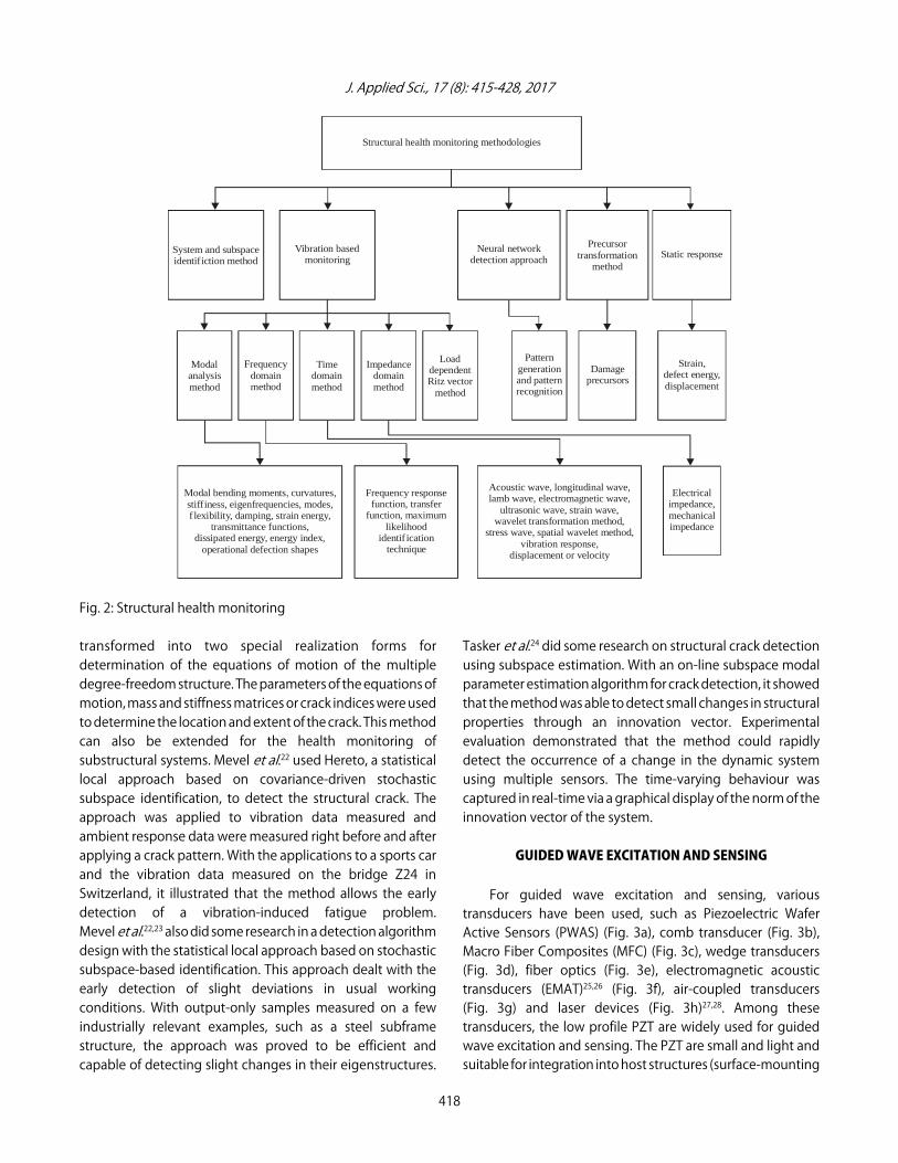
It is well established that structural health is directlyrelated to structural performance that can be regarded as theprimary factor in establishing the operational safety of thestructure. There are different kinds of methods that can beused to detect the health of a structure and some of these areconventional methods such as vibration-based or parameterestimation methods, while others are based on new concepts.Many of the current methods for crack detection use thesystem or subspace identification technique; others use crackdetection algorithms that bypass system identification andrely directly on the measured data to identify the crack. Thevibration monitoring of a structure has gained popularity overthe past decade due to the relative ease of instrumentationinvolved and the powerful system identification techniquesdeveloped for structural health monitoring. The main ideahere is to replace the visual, systematic inspections by healthmonitoring systems that can continuously acquire and analyzevibration data and allow identification of crack at an earlystage. More recently, a number of researchers have usedneural networks for crack detection that can be consideredto be a two-phase method involving a patterngeneration/training phase and a pattern recognition phase.Another concept used for crack detection, known as thePrecursor Transformation Method (PTM) is based ondetermining the causes (precursors) of change in themeasured state of the structure under non-variable loadingconditions (e.g., dead loads in bridges). Based on differentmethods and environments involved, a variety of parametersand criteria are used for measurement and crack detection.The different types of structural health monitoring, signalprocessing and analysis methods used (proposed) in theliterature as indicated in Fig. 2.
System and subspace identification: The systemidentification technique is one that constructs a model of thecracked structure. By comparing the model of the crackedstructure with that of the uncracked structure, the crack isdetected. Lindner and Goff20 did some research in this field.Liu and Rao21 used a parameter identification method todetermine the crack of a structure. With the subspace systemidentification algorithm, a structure state-space model wasobtained. The identified state-space model was then
417
J. Applied Sci., 17 (8): 415-428, 2017
Structural health monitoring methodologies
Modal bending moments, curvatures,stiffiness, eigenfrequencies, modes,
f lexibility, damping, strain energy,
transmittance functions,dissipated energy, energy index,
operational defection shapes
Frequency responsefunction, transfer
function, maximumlikelihood
identif ication
technique
Acoustic wave, longitudinal wave,lamb wave, electromagnetic wave,
ultrasonic wave, strain wave,wavelet transformation method,
stress wave, spatial wavelet method,vibration response,
displacement or velocity
Electricalimpedance,mechanicalimpedance
Modalanalysismethod
Timedomainmethod
Frequencydomainmethod
Impedancedomainmethod
LoaddependentRitz vector
method
Patterngenerationand patternrecognition
Damageprecursors
Strain,defect energy,displacement
System and subspaceidentifiction method
Vibration basedmonitoring
Neural networkdetection approach
Precursortransformation
methodStatic response
Fig. 2: Structural health monitoring
transformed into two special realization forms fordetermination of the equations of motion of the multipledegree-freedom structure. The parameters of the equations ofmotion, mass and stiffness matrices or crack indices were usedto determine the location and extent of the crack. This methodcan also be extended for the health monitoring ofsubstructural systems. Mevel et al.22 used Hereto, a statisticallocal approach based on covariance-driven stochasticsubspace identification, to detect the structural crack. Theapproach was applied to vibration data measured andambient response data were measured right before and afterapplying a crack pattern. With the applications to a sports carand the vibration data measured on the bridge Z24 inSwitzerland, it illustrated that the method allows the earlydetection of a vibration-induced fatigue problem.Mevel et al.22,23 also did some research in a detection algorithmdesign with the statistical local approach based on stochasticsubspace-based identification. This approach dealt with theearly detection of slight deviations in usual workingconditions. With output-only samples measured on a fewindustrially relevant examples, such as a steel subframestructure, the approach was proved to be efficient andcapable of detecting slight changes in their eigenstructures.
Tasker et al.24 did some research on structural crack detectionusing subspace estimation. With an on-line subspace modalparameter estimation algorithm for crack detection, it showedthat the method was able to detect small changes in structuralproperties through an innovation vector. Experimentalevaluation demonstrated that the method could rapidlydetect the occurrence of a change in the dynamic systemusing multiple sensors. The time-varying behaviour wascaptured in real-time via a graphical display of the norm of theinnovation vector of the system.
GUIDED WAVE EXCITATION AND SENSING
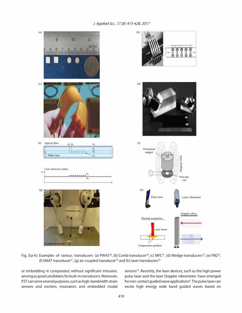
For guided wave excitation and sensing, varioustransducers have been used, such as Piezoelectric WaferActive Sensors (PWAS) (Fig. 3a), comb transducer (Fig. 3b),Macro Fiber Composites (MFC) (Fig. 3c), wedge transducers(Fig. 3d), fiber optics (Fig. 3e), electromagnetic acoustictransducers (EMAT)25,26 (Fig. 3f), air-coupled transducers(Fig. 3g) and laser devices (Fig. 3h)27,28. Among thesetransducers, the low profile PZT are widely used for guidedwave excitation and sensing. The PZT are small and light andsuitable for integration into host structures (surface-mounting
418
J. Applied Sci., 17 (8): 415-428, 2017
Fig. 3(a-h): Examples of various transducers (a) PWAS29, (b) Comb transducer30, (c) MFC31, (d) Wedge transducers32, (e) FBG33,(f) EMAT transducer27, (g) air-coupled transducer34 and (h) laser transducers35
or embedding in composites) without significant intrusion,serving as good candidates for built-in transducers. Moreover, PZT can serve several purposes, such as high-bandwidth strainsensors and exciters, resonators and embedded modal
sensors12. Recently, the laser devices, such as the high powerpulse laser and the laser Doppler vibrometer, have emergedfor non-contact guided wave applications4. The pulse laser canexcite high energy wide band guided waves based on
419
Temperature gradient
Thermal expansion
Doppler effect
Laser beam
Pulse laser Laser vibrometer
(a) (b)
(c) (d)
Fiber core
Core refractive index
Optical fiber n0
n1 n2
n3
n3
n2
n
(e) (f)
Permanent magnet
Mag
neti
c fi
eld
Pancake coil
(g) (h)
Composite sample
X3
X2
X1
Scanning axis
J. Applied Sci., 17 (8): 415-428, 2017
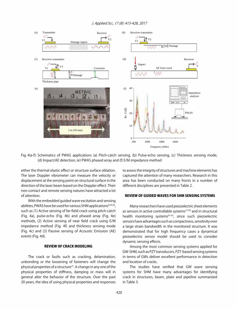
Fig. 4(a-f): Schematics of PWAS applications (a) Pitch-catch sensing, (b) Pulse-echo sensing, (c) Thickness sensing mode,(d) Impact/AE detection, (e) PWAS phased array and (f) E/M impedance method
either the thermal elastic effect or structure surface oblation.The laser Doppler vibrometer can measure the velocity ordisplacement at the sensing point on structural surface in thedirection of the laser beam based on the Doppler effect. Theirnon-contact and remote sensing natures have attracted a lotof attention.
With the embedded guided wave excitation and sensingabilities, PWAS have be used for various SHM applications8,29,36,such as (1) Active sensing of far-field crack using pitch-catch(Fig. 4a), pulse-echo (Fig. 4b) and phased array (Fig. 4e)methods, (2) Active sensing of near field crack using E/Mimpedance method (Fig. 4f) and thickness sensing mode(Fig. 4c) and (3) Passive sensing of Acoustic Emission (AE)events (Fig. 4d).
REVIEW OF CRACK MODELING
The crack or faults such as cracking, delamination,unbonding or the loosening of fasteners will change thephysical properties of a structure37. A change in any one of thephysical properties of stiffness, damping or mass will ingeneral alter the behavior of the structure. Over the past20 years, the idea of using physical properties and responses
to assess the integrity of structures and machine elements hascaptured the attention of many researchers. Research in thisarea has been conducted on many fronts in a number ofdifferent disciplines are presented in Table 2.
REVIEW OF GUIDED WAVES FOR SHM SENSING SYSTEMS
Many researchers have used piezoelectric sheet elementsas sensors in active controllable systems57-60 and in structuralhealth monitoring systems61-63, since such piezoelectricsensors have advantages such as compactness, sensitivity overa large strain bandwidth in the monitored structure. It wasdemonstrated that for high frequency cases a dynamicalpiezoelectric sensor model should be used to considerdynamic sensing effects.
Among the most common sensing systems applied forGW-SHM, such as PZT transducers, PZT-based sensing systemsin terms of GWs deliver excellent performance in detectionand location of cracks.
The studies have verified that GW wave sensingsystems for SHM have many advantages for identifyingcrack in structures, beam, plate and pipeline summarizedin Table 3.
420
(a) (b)
Impact AE from crack
Receiver
V
Receiver transmitter
Damage
V1V2 V1 V2
Damage region
ReceiverTransmitter
(c) (d)
Thickness pipe
Receiver transmitter
Damage
Corrosion V1 V2
2 in (50 mm)
(e) (f)
200 1000 1800 2600
Frequency (kHz)
40
30
20
10
0
PWAS
Impedance analyzer
Re.
Z (S
)

J. Applied Sci., 17 (8): 415-428, 2017
421
Table 2: Survey of guided wave crack detection technique
References
Methods proposed
Materials and sample shapes
Crack types
Remarks
Lowe et al.38
Propagate guided waves
Pipeline
Corrosion detection
Focused on sensitivity to defects of the propagation of the reflection and their
modes. In addition, the work validate by finite element simulations and precise
laboratory experiments
Liew and Veidt39
Neural networks damage
Bars
Laminar defects
The proposed neural network accurately predicated damage location and depth
identification
based on fusion data process that overlapping test
Lu40
Physical crack growth model
Pipeline
Corrosion detection
Investigate the liquid pipeline crack growth and it’s controlled by the corrosion
fatigue mechanism
Tan et al.41
Load-independent creep
Pipeline
Three-dimensional creep
Focused on correlation between test specimens and the 3-D axially cracked
constraint parameter
crack-tip
pipelines. In addition more analysed done to check the effects of loading levels, crack
sizes and geometries on pipeline crack
Wang et al.28
Shear horizontal guided
Pipeline
Axial crack
The author also verified the proposed method by comparing with 3D numerical
waves propagating
modelling FEM package for quantitative testing of axial pipeline cracking
Pan et al.42
A failure analysis
Stainless steel pipeline
Intergranular crack
Investigated pressure pipeline crack after two years servicing under elevated
temperature by ABAQUS finite element software. The result show better
understanding of effect of pipeline material mechanical properties and stress
distribution on failure mechanisms
Cheng and Chen43
Hydrogen embrittlement
Pipeline carbon steels
Corrosion detection
The proposed method fatigue predicted crack growth rate and compared with
experimental data
Liu et al.44
Linear magnetic dipole model
Pipeline
Axial crack
The author introduced a new relationship between geometry characteristics of
axial cracks and magnetic flux leakage signals and show that detection accuracy
depended on influence of magnetic fields near the magnetic poles
Eybpoosh et al.45
Unsupervised
Aluminum pipeline
Different damage
The author focused on the effect of operational conditions and varying
feature-extraction method
environmental on aluminum pipeline damage detection based on different wave
modes propagation characteristics. In addition, empirical validation also conducted
a pipeline structural abnormality including multiple small, different types and
locations, in a steel pipe and under different temperature ranges
Xu et al.46
Generating longitudinal
Pipeline
Different damage
Studied the effect on the excitation coil lift-off distances on alternating magnetic
guided waves model
field strength generated in pipeline
Wang et al.47
Defect’s geometric parameters
Pipeline
Different damage
Investigated the complexity of reflection signals features from defect edge for
different defects geometric to determine the extraction signals to enable a
quantitative and accurate pipeline defection
Cobb et al.48
Measure guided wave
Pipeline
Corrosion detection
Experimentally investigated the pipeline configurations (coated and uncoated)
attenuation
for corrosion detection based on guided wave attenuation with frequency range
10-140 kHz at ambient temperature

J. Applied Sci., 17 (8): 415-428, 2017
422
Table 2: Continue
References
Methods proposed
Materials and sample shapes
Crack types
Remarks
Peter and Wang49
Optimized matching
Pipeline
Axial crack and corrosion
The author introduced a new optimized matching pursuit method for directly
pursuit method
and accurately the pipeline axial defect detection. The analysis of the interference
between the reflection components for efficient defect information extraction. In
addition, proposed method enhances signal-to-noise ratio of reflection signal, but
also characterizes
Clough et al.50
A screening technique
pipeline
Circumferential crack
The screening technique has good capability on defect sizing and detection. Also
Finite element method has been used to simulate the pipeline focused on reflections
that occur and the mode conversions
Lowe et al.51
Longitudinal ultrasonic
Pipeline
Different damage
The author for reduces the cost and weight on longitudinal guided wave mode for
guided wave
better inspection by adopting isolation transducers with 20-100 kHz operating range
frequencies
Jiang and Chen52
Fatigue crack propagation
Pipeline
Mechanical damage
The author approved that fatigue crack propagation rate will increase by
mechanical damage and the synthetic soil which led to shorten the pipeline service
life
Koppe et al.53
Lamb waves
Pipeline
Different crack
Investigated the practicability of a Lamb Wave Generator (LWG) for differentiate and
classify different defect types. In addition introduce a proper excitation, transmission
and reflection of lamb wave characteristics based on relevant sample parameters
(dimensions and specimen materials)
Sun and Li54
Liner sound source localization
Stainless steel pipeline
Different crack
The author introduced crack simulation model using Nielsen-Hsu Pencil Lead Break
method identify Hit lockout time, Hit definition time, peak definition time and timing
parameters for acoustic emission signal transducer
Kim et al.55
Small yoke-type magnetizer
Pipeline
Axis-directional crack
The DMF extracted crack for an arc-directional crack and an axis-directional crack
Piddubniak et al.56
The scattering of plane
Steel shell
Long Crack
The author investigate echo-signals, directivity patterns of the scattered field
non-stationary sound wave
and scattering amplitudes for the steel shell. in addition, the vibrations of steel shell
are modelled based on Kirchhoff-thin shell-theory
J. Applied Sci., 17 (8): 415-428, 2017
423
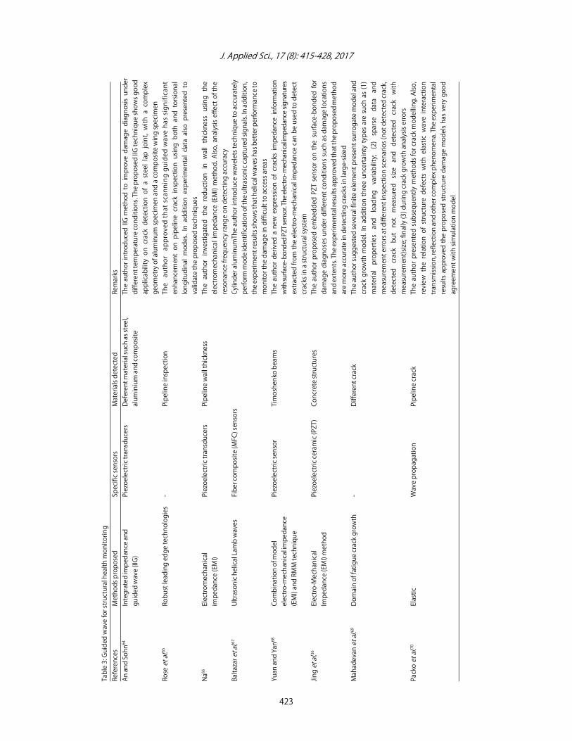
Table 3: Guided wave for structural health monitoring
References
Methods proposed
Specific sensors
Materials detected
Remarks
An and Sohn64
Integrated impedance and
Piezoelectric transducers
Deferent material such as steel,
The author introduced IIG method to improve damage diagnosis under
guided wave (IIG)
aluminium and composite
different temperature conditions. The proposed IIG technique shows good
applicability on crack detection of a steel lap joint, with a complex
geometry of aluminum specimen and a composite wing specimen
Rose et al.65
Robust leading edge technologies
-Pipeline inspection
The author approved that scanning guided wave has significant
enhancement on pipeline crack inspection using both and torsional
longitudinal modes. In addition experimental data also presented to
validate the proposed techniques
Na66
Electromechanical
Piezoelectric transducers
Pipeline wall thickness
The author investigated the reduction in wall thickness using the
impedance (EMI)
electromechanical impedance (EMI) method. Also, analysis effect of the
resonance frequency range on detecting accuracy
Baltazar et al.67
Ultrasonic helical Lamb waves
Fiber composite (MFC) sensors
Cylinder aluminumThe author introduce wavelets technique to accurately
perform mode identification of the ultrasonic captured signals. In addition,
the experiment results shows that helical waves has better performance to
monitor the damage in difficult to access areas
Yuan and Yan68
Combination of model
Piezoelectric sensor
Timoshenko beams
The author derived a new expression of cracks impedance information
electro-mechanical impedance
with surface- bonded PZT sensor. The electro- mechanical impedance signatures
(EMI) and RMM technique
extracted from the electro-mechanical impedance can be used to detect
cracks in a structural system
Jing et al.36
Electro-Mechanical
Piezoelectric ceramic (PZT)
Concrete structures
The author proposed embedded PZT sensor on the surface-bonded for
Impedance (EMI) method
damage diagnoses under different conditions such as damage locations
and extents. The experimental results approved that the proposed method
are more accurate in detecting cracks in large-sized
Mahadevan et al.69
Domain of fatigue crack growth
-Different crack
The author suggested several finite element present surrogate model and
crack growth model. In addition three uncertainty types are such as (1)
material properties and loading variability; (2) sparse data and
measurement errors at different inspection scenarios (not detected crack,
detected crack but not measured size and detected crack with
measurement)size; finally (3) during crack growth analysis errors
Packo et al.70
Elastic
Wave propagation
Pipeline crack
The author presented subsequently methods for crack modelling. Also,
review the relation of structure defects with elastic wave interaction
transmission, reflection and other complex phenomena. The experimental
results approved the proposed structure damage models has very good
agreement with simulation model

J. Applied Sci., 17 (8): 415-428, 2017
424
Table 3: Continue
References
Methods proposed
Specific sensors
Materials detected
Remarks
Sun et al.71
Fatigue
Crack growth model
Different crack depths and
The author presented new relation of cracked beam natural frequency.
locations
The numerical simulation model with sceneries including different crack
depths and locations also proposed. From the result, it can that the cracks
deep closed to fixed end will lead to the faster rate of descent of the first
order natural frequency and decrease of natural frequency
Gaith et al.72
Artificial Neural
Solid cantilever beams
Different crack
The author proposed ANN model to predicted the cracks location and
Network (ANN)
depths and size. In addition the ANN data training data collected from
ANSYS software
Qatu et al.73
3-point
Pulse-echo technique
Aluminium plate
The author suggest wigner-ville distribution to eliminate noise and
calculate the Time of Flight. Also, ABAQUS software used to simulate lamb
wave propagation and determine the effect of damage size on the damage
localization
He et al.74
Crack
Size quantification
Different crack
The author studied Lamb wave propagation mechanism to predicate a
method
crack size based on finite element method including two damage sensitive
features: correlation coefficients and normalized amplitude. The simulation
result verified the proposed model by series of coupon data caused
environmental conditions and manufacture
Afzal et al.75
Detecting crack damage
Fiber Optic sensors (FOSs)
Concrete structures
The author presented review of various techniques used in crack damage
detection using Fiber optic sensors. More information related to FOSs
characteristics provided for more precise and accurate crack damage
detection
Friswell and Penny76
Breathing cracks
-Beam elements
The author investigated the effect of breathing cracks excitation where the
beam stiffness is bilinear. In addition, crack modelling compares the
different techniques using crack flexibility and low frequency vibration
Duan et al.77
Different structural
Piezoelectric sensor
Plate, pipeline and beam
The author focused proposer selection piezoelectric sensors and
health monitoring
structures for damage detection
actuators types for crack detection including (beam, plate and pipeline
damage detection). In addition, analysis of plain piezoelectric and inter
digital transducer and their applications in pipeline, plate, beam and
structures for damage detection technique are examined
J. Applied Sci., 17 (8): 415-428, 2017
CURRENT APPROACH IN INDUSTRY
In the pipeline industry, a single method for detecting ormonitoring damage in a pipeline does not currently exist.Instead, industries typically implement a combination ofseveral different techniques. For the oil and natural gaspipeline industry, destructive and non-destructive inspectiontechniques are commonly used together to ensure theintegrity of transmission lines78-82. These techniques typicallyrequire the pipeline system to be temporarily taken out ofoperation. The most common destructive technique is ahydrostatic test. For oil pipelines, a hydrostatic test involvespressurizing the pipeline to a point greater than the maximumoperating pressure. The pressure is then observed for severalhours to determine if any leaks are present, because ahydrostatic test could potentially cause a leak or rupture, allthe hazardous materials in the pipeline must be replaced withwater to prevent environmental damage, because of serviceinterruptions and water removal difficulties, hydrostatictesting is not used with natural gas pipelines.
When the geometry of the pipeline permits,non-destructive techniques are primarily used to ensure thestructure’s integrity. Such techniques commonly involvesending a magnetic flux or ultrasonic inspection device downthe inside of the pipeline. The size of the device available limitsthe smallest size pipe that can be tested and the radius ofbends also limits the ability to use a particular device. Thesedevices perform best in oil pipelines because petroleumproducts act as a good coupling between the instrument andthe pipe wall. Accordingly, these techniques do not require oilpipelines to be emptied, contrary to hydrostatic testing.However, natural gas pipelines are more complicated becausea gas does not provide good coupling for the testing device.Therefore, operators of natural gas pipelines have turned todirect assessment procedures for the determination of theintegrity of their systems.
As evidenced by the documented cases of pipelineaccidents, the current approaches used in industry to monitorthe structural integrity of pipelines is not 100% effective. Eventhough pipelines are one of the safest modes of energytransportation, there is still justification for seekingimprovements. The associated costs of property damage fromaccidents are quite significant, not to mention the enormousloss from each and every fatality. Also, the implementation ofboth destructive and non-destructive inspection techniquesrequires the pipeline to be taken temporarily out of service,which adds to the costs to an operator. Therefore, thedevelopment of a more reliable, cheaper monitoring systemwould have countless advantages for pipeline operators.
Hence, innovative monitoring systems and defectsdiagnosis techniques should be in place to insure thesustainability of the infrastructure, i.e. pipelines and theassociated equipment to insure their integrity andcontinuity80,83.
CONCLUSION
This study focused on various vibration-based SHMmethods, elastic-wave-based method, referred as guidedwave method which employed as the fundamental tool forcrack inspection. The GW method is an active SHMtechnology, which is a combination of Ultrasonic testing andAcoustic emission approaches. The technique is a global SHMmethod, which also has capability to detect local cracks of anystructure. A complete SHM methodology should be able toidentify crack occurrence in the structure, if any, locatestructural crack and quantitatively describe the severity ofcrack. In addition, GW method has a number of advantagessuch as simple inspection methodology; time- and costeffectiveness; ability of wide area inspection with a limitednumber of transducers, fast and repeatable inspectioncapability; sensitivity to small cracks; and mode and frequencytuning capability.
SIGNIFICANCE STATEMENTS
This study presents a state-of-the-art review on variousmethodologies for the integration of GWs and SHM. A broadclassification of important research works was presentedalong with their shortcomings and contributions. Acomparative analysis in tabular form of various guided wavesapproaches has also been given. This study is very helpful forthose who want to build up a level of understanding in thearea of pipeline crack detection and classification based ondifferent techniques including artificial neural networks.
ACKNOWLEDGMENT
Authors very thankful to Faculty of Mechanical andManufacturing. Eng., University Tun Hussein Onn Malaysia(UTH) for financial support (RDU1503116) this project.
REFERENCES
1. Majumder, M., T.K. Gangopadhyay, A.K. Chakraborty,K. Dasgupta and D.K. Bhattacharya, 2008. Fibre Bragg gratingsin structural health monitoring-Present status andapplications. Sensors Actuators A: Phys., 147: 150-164.
425

J. Applied Sci., 17 (8): 415-428, 2017
2. Mieloszyk, M., L. Skarbek, M. Krawczuk, W. Ostachowicz andA. Zak, 2011. Application of fibre Bragg grating sensors forstructural health monitoring of an adaptive wing. SmartMater. Struct., Vol. 20.
3. Glisic, B. and D. Inaudi, 2008. Fibre Optic Methods forStructural Health Monitoring. John Wiley and Sons, New York,ISBN: 9780470517802, Pages: 276.
4. Sohn, H., 2014. Noncontact laser sensing technology forstructural health monitoring and nondestructive testing.Proceedings of the Sensors and Smart StructuresTechnologies for Civil, Mechanical and Aerospace Systems,May 6, 2014, San Diego, CA., USA., pp: 10-12.
5. Pandey, A.K., M. Biswas and M.M. Samman, 1991.Damage detection from changes in curvature mode shapes.J. Sound Vibr., 145: 321-332.
6. Worden, K. and D.J. Inman, 2010. Modal Vibration Methods inStructural Health Monitoring. In: Encyclopedia of AerospaceEngineering, Blockley, R. and W. Shyy (Eds.). Vol. 9, Wiley,New York.
7. Qing, X.P., S.J. Beard, A. Kumar, T.K. Ooi and F.K. Chang, 2007.Built-in sensor network for structural health monitoring ofcomposite structure. J. Intell. Mater. Syst. Struct., 18: 39-49.
8. Giurgiutiu, V., B. Xu and W. Liu, 2010. Development andtesting of high-temperature piezoelectric wafer activesensors for extreme environments. Struct. Health Monit.,9: 513-525.
9. Doherty, C. and W.K. Chiu, 2012. Scattering ofultrasonic-guided waves for health monitoring of fuel weepholes. Struct. Health Monit., 11: 27-42.
10. Zagrai, A., D. Doyle, V. Gigineishvili, J. Brown, H. Gardenier andB. Arritt, 2010. Piezoelectric wafer active sensor structuralhealth monitoring of space structures. J. Intell. Mater. Syst.Struct., 21: 921-940.
11. Achenbach, J., 2012. Wave Propagation in Elastic Solids.Elsevier, USA., ISBN: 9780080934716, Pages: 440.
12. Giurgiutiu, V. and A. Cuc, 2005. Embedded non-destructiveevaluation for structural health monitoring, damagedetection and failure prevention. Shock Vibr. Digest,37: 83-105.
13. Kundu, T., S. Das and K.V. Jata, 2009. Health monitoring of athermal protection system using Lamb waves. Struct. HealthMonit., 8: 29-45.
14. Mahzan, S. and M.M.F. Elghanudi, 2006. Feasibility study ofstructural health monitoring towards pipeline corrosionmonitoring: A review. ARPN J. Eng. Applied Sci.,11: 8673-8678.
15. Chang, F.K., J.F. Markmiller, J.B. Ihn and K.Y. Cheng, 2007. Apotential link from damage diagnostics to health prognosticsof composites through built-in sensors. J. Vibr. Acoust.,129: 718-729.
16. Boller, C., C. Biemans, W.J. Staszewski, K. Worden andG.R. Tomlinson, 1999. Structural damage monitoring basedon an actuator-sensor system. Proceedings of the SPIE's 6thInternational Symposium on Smart Structures and Materials,March 1-4, 1999, Newport Beach, CA., USA.
17. Worden, K. and J.M. Dulieu-Barton, 2004. An overview ofintelligent fault detection in systems and structures.Struct. Health Monit., 3: 85-98.
18. Farrar, C.R. and K. Worden, 2007. An introduction to structuralhealth monitoring. Philos. Trans. Royal Soc. Lon. A: Math.Phys. Eng. Sci., 365: 303-315.
19. Rytter, A., 1993. Vibrational based inspection of civilengineering structures. Ph.D. Thesis, University of Aalborg,Aalborg.
20. Lindner, D.K. and R. Goff, 1993. Damage detection, locationand estimation for space trusses. Proceedings of the SPIE'sSymposium on Smart Structures and Materials, February 1-4,1993, Albuquerque, New Mexico.
21. Liu, P. and V.S. Rao, 2000. Structural health monitoring usingparameter identification methods. Proceedings of the SPIE's7th Annual International Symposium on Smart Structures andMaterials, March 6-8, 2000, Newport Beach, CA., USA.,pp: 792-805.
22. Mevel, L., M. Basseville, A. Benveniste, M. Goursat,M. Abdelghani and L. Hermans, 1999. On the application of asubspace-based fault detection method. Proceedings of the17th International Modal Analysis Conference, February 1999,Kissimmee, FL., pp: 35-41.
23. Mevel, L., L. Hermans and H. van der Auweraer, 2000. Healthmonitoring of a concrete three-span bridge. Proceedings ofthe IMAC-XVIII: A Conference on Structural Dynamics,February 7-10, 2000, San Antonio, TX., USA., pp: 690-694.
24. Tasker, F., B. Dunn and S. Fisher, 1999. Online structuraldamage detection using subspace estimation. Proceedingsof the Aerospace Conference, Volume 2, March 7, 1999,Snowmass at Aspen, CO., USA.
25. Bhuiyan, M.Y., Y. Shen and V. Giurgiutiu, 2016. Guided wavebased crack detection in the rivet hole using global analyticalwith local fem approach. Materials, 9: 602-619.
26. Hettler, J., M. Tabatabaeipour, S. Delrue andK. van den Abeele, 2016. Linear and nonlinear guided waveimaging of impact damage in CFRP using a probabilisticapproach. Materials, Vol. 9. 10.3390/ma9110901.
27. Wilcox, P., M. Lowe and P. Cawley, 2005. Omnidirectionalguided wave inspection of large metallic plate structuresusing an EMAT array. IEEE Trans. Ultrason. Ferroelectr. Freq.Control, 52: 653-665.
28. Wang, S., S. Huang, W. Zhao and Z. Wei, 2015. 3D modeling ofcircumferential SH guided waves in pipeline for axial crackingdetection in ILI tools. Ultrasonics, 56: 325-331.
426
J. Applied Sci., 17 (8): 415-428, 2017
29. Santoni, G.B., L. Yu, B. Xu and V. Giurgiutiu, 2007. Lambwave-mode tuning of piezoelectric wafer active sensors forstructural health monitoring. J. Vibr. Acoust., 129: 752-762.
30. Rose, J.L., 2000. Guided wave nuances for ultrasonicnondestructive evaluation. IEEE Trans. Ultrason. Ferroelectr.Freq. Control, 47: 575-583.
31. Raghavan, A.C. and C.E.S. Cesnik, 2007. Review ofguided-wave structural health monitoring. Shock Vibr.Digest, 39: 91-114.
32. Culshaw, B., S.G. Pierce and W.J. Staszekski, 1998. Conditionmonitoring in composite materials: An integrated systemsapproach. Proc. Inst. Mech. Eng. Part I: J. Syst. Control Eng.,212: 189-202.
33. Rajic, N., C. Davis and A. Thomson, 2009. Acoustic-wave-modeseparation using a distributed Bragg grating sensor.Smart Mater. Struct., Vol. 18.
34. Ke, W., M. Castaings and C. Bacon, 2009. 3D finite elementsimulations of an air-coupled ultrasonic NDT system.NDT & E Int., 42: 524-533.
35. Lee, H., H. Sohn, S. Yang and J. Yang, 2014. Monitoring ofpipelines in nuclear power plants by measuring laser-basedmechanical impedance. Smart Mater. Struct., Vol. 23.
36. Jing, Y., Z. Hongping and H. Minshui, 2010. Numerical studyof structure health monitoring using surface-bonded andembedded PZT transducers. Proceedings of the InternationalConference on Mechanic Automation and ControlEngineering, June 26-28, 2010, Wuhan, China.
37. Zaleha, M., S. Mahzan and I.M. Izwana, 2014. Damage sizeclassification of natural fibre reinforced composites usingneural network. Adv. Mater. Res., 911: 60-64.
38. Lowe, M.J.S., D.N. Alleyne and P. Cawley, 1998. Defectdetection in pipes using guided waves. Ultrasonics,36: 147-154.
39. Liew, C.K. and M. Veidt, 2009. Pattern recognition of guidedwaves for damage evaluation in bars. Pattern Recognit. Lett.,30: 321-330.
40. Lu, B.T., 2014. Further study on crack growth model of buriedpipelines exposed to concentrated carbonate-bicarbonatesolution. Eng. Fract. Mech., 131: 296-314.
41. Tan, J.P., S.T. Tu, G.Z. Wang and F.Z. Xuan, 2015.Characterization and correlation of 3-D creep constraintbetween axially cracked pipelines and test specimens.Eng. Fract. Mech., 136: 96-114.
42. Pan, J.H., Z.C. Fan and N.S. Zong, 2016. Research on weldcracking of TP321H stainless steel pipeline under elevatedtemperature. Int. J. Pressure Vessels Piping, 148: 1-8.
43. Cheng, A. and N.Z. Chen, 2017. Fatigue crack growthmodelling for pipeline carbon steels under gaseous hydrogenconditions. Int. J. Fatigue, 96: 152-161.
44. Liu, B., L.Y. He, H. Zhang, Y. Cao and H. Fernandes, 2017. Theaxial crack testing model for long distance oil-gas pipelinebased on magnetic flux leakage internal inspection method.Measurement, 103: 275-282.
45. Eybpoosh, M., M. Berges and H.Y. Noh, 2017. An energy-basedsparse representation of ultrasonic guided-waves for onlinedamage detection of pipelines under varying environmentaland operational conditions. Mech. Syst. Signal Process.,82: 260-278.
46. Xu, J., Z. Xu and X. Wu, 2012. Research on the lift-off effect ofgenerating longitudinal guided waves in pipes based onmagnetostrictive effect. Sensors Actuators A: Phys.,184: 28-33.
47. Wang, X., P.W. Tse, C.K. Mechefske and M. Hua, 2010.Experimental investigation of reflection in guidedwave-based inspection for the characterization of pipelinedefects. NDT E Int., 43: 365-374.
48. Cobb, A.C., H. Kwun, L. Caseres and G. Janega, 2012. Torsionalguided wave attenuation in piping from coating, temperatureand large-area corrosion. NDT E Int., 47: 163-170.
49. Peter, W.T. and X. Wang, 2013. Characterization of pipelinedefect in guided-waves based inspection throughmatching pursuit with the optimized dictionary. NDT & E Int.,54: 171-182.
50. Clough, M., M. Fleming and S. Dixon, 2017. Circumferentialguided wave EMAT system for pipeline screening using shearhorizontal ultrasound. NDT E Int., 86: 20-27.
51. Lowe, P.S., R. Sanderson, S.K. Pedram, N.V. Boulgouris andP. Mudge, 2015. Inspection of pipelines using the firstlongitudinal guided wave mode. Phys. Procedia, 70: 338-342.
52. Jiang, Y. and M. Chen, 2012. Researches on the fatigue crackpropagation of pipeline steel. Energy Procedia, 14: 524-528.
53. Koppe, E., M. Bartholmai and J. Prager, 2012. Device conceptfor the generation of guided waves for early damagedetection. Procedia Eng., 47: 1185-1188.
54. Sun, L. and Y. Li, 2010. Acoustic emission sound sourcelocalization for crack in the pipeline. Proceedings of theControl and Decision Conference, May 26-28, 2010, China.
55. Kim, J., M. Choi and J. Lee, 2011. Employing magnetic sensorarray for inspecting cracks in a pipeline. Proceedings of theSensors Applications Symposium, February 22-24, 2011,San Antonio, TX., USA.
56. Piddubniak, O., N. Piddubniak and S. Brzozowska, 2013.Analysis of acoustic echo-signal from gas pipeline withlong crack. Proceedings of the 18th InternationalSeminar/Workshop on Direct and Inverse Problems ofElectromagnetic and Acoustic Wave Theory, September23-26, 2013, Lviv, Ukraine, pp: 219-225.
57. Lee, C.K. and T.C. O'Sullivan, 1991. Piezoelectric strain rategages. J. Acoust. Soc. Am., 90: 945-953.
58. Qiu, J. and J. Tani, 1995. Vibration control of a cylindricalshell using distributed piezoelectric sensors and actuators.J. Intell. Mater. Syst. Struct., 6: 474-481.
59. Hoummady, M., A. Campitelli and W. Wlodarski, 1997.Acoustic wave sensors: Design, sensing mechanisms andapplications. Smart Mater. Struct., Vol. 6.
427
J. Applied Sci., 17 (8): 415-428, 2017
60. Lim, Y.H., S.V. Gopinathan, V.V. Varadan and V.K. Varadan,1999. Finite element simulation of smart structures using anoptimal output feedback controller for vibration and noisecontrol. Smart Mater. Struct., Vol. 8.
61. Samuel, P.D. and D.J. Pines, 1997. Health monitoring anddamage detection of a rotorcraft planetary geartrainsystem using piezoelectric sensors. Proceedings of the SPIE's4th Annual Symposium on Smart Structures and Materials,March 3-6, 1997, San Diego, CA., USA.
62. Chiu, W.K., M. Heller and R. Jones, 1997. Determination of thestress components of an array of piezoelectric sensors: Anumerical study. Smart Mater. Struct., Vol. 6.
63. Wang, B.T. and R.L. Chen, 2000. The use of piezoceramictransducers for smart structural testing. J. Intell. Mater. Syst.Struct., 11: 713-724.
64. An, Y.K. and H. Sohn, 2012. Integrated impedance and guidedwave based damage detection. Mech. Syst. Signal Process.,28: 50-62.
65. Rose, J.L., Y. Cho and M.J. Avioli, 2009. Next generationguided wave health monitoring for long range inspection ofpipes. J. Loss Prev. Process Ind., 22: 1010-1015.
66. Na, W.S., 2017. Possibility of detecting wall thickness lossusing a PZT based structural health monitoringmethod for metal based pipeline facilities. NDT E Int.,88: 42-50.
67. Baltazar, A., E. Rojas and R. Mijarez, 2015. Structuralhealth monitoring in cylindrical structures using helicalguided wave propagation. Phys. Procedia,70: 686-689.
68. Yuan, L. and W. Yan, 2009. Crack detection in structuralsystems using electro-mechanical signatures. Proceedings ofthe Asia-Pacific Power and Energy Engineering Conference,March 27-31, 2009, Wuhan, China, pp: 1-4.
69. Mahadevan, S., Y. Ling and S. Sankararaman, 2011.Confidence assessment in model-based structural healthmonitoring. Proceedings of the IEEE Aerospace Conference,March 5-12, 2011, Big Sky, MT., USA .
70. Packo, P., L. Ambrozinski and T. Uhl, 2011. Structure damagemodelling for guided waves-based SHM systems testing.Proceedings of the 4th International Conference onModeling, Simulation and Applied Optimization, April 19-21,2011, Kuala Lumpur, Malaysia, pp: 1-6.
71. Sun, M., F. Wan and Z. Qin, 2012. Health monitoring forpropagating crack faults. Proceedings of the IEEE Conferenceon Prognostics and System Health Management, May 23-25,2012, Beijing, China, pp: 1-6.
72. Gaith, M., M.E.H. Assad, A. Sedaghat, M. Hiyasat andS. Alkhatib, 2015. Neural network usage in structural crackdetection. Proceedings of the International Conference onIndustrial Engineering and Operations Management,March 3-5, 2015, Dubai, United Arab Emirates, pp: 1-5.
73. Qatu, K.M., A. Abdelgawad and K. Yelamarthi, 2016. Structuredamage localization using a reliable wave damage detectiontechnique. Proceedings of the International Conference onElectrical, Electronics and Optimization Techniques,March 3-5, 2016, Chennai, India, pp: 1959-1962.
74. He, J., Y. Ran, J. Yang and W. Zhang, 2016. A novel crack sizequantification method based on lamb wave simulation.Proceedings of the Prognostics and System HealthManagement Conference, October 19-21, 2016, Chengdu,Sichuan, China, pp: 1-6.
75. Afzal, M.H.B., S. Kabir and O. Sidek, 2012. An in-depth review:Structural health monitoring using fiber optic sensor.IETE Techn. Rev., 29: 105-113.
76. Friswell, M.I. and J.E.T. Penny 2002. Crack modeling forstructural health monitoring. Struct. Health Monit.,1: 139-148.
77. Duan, W.H., Q. Wang and S.T. Quek, 2010. Applications ofpiezoelectric materials in structural health monitoring andrepair: Selected research examples. Materials, 3: 5169-5194.
78. Ali, K.B., A.N. Abdalla, D. Rifai and M.A. Faraj, 2017. Review onsystem development in eddy current testing and techniquefor defect classification and characterization. IET Circ. DevicesSyst. 10.1049/iet-cds.2016.0327.
79. Rifai, D., A.N. Abdalla, K. Ali and R. Razali, 2016. Giantmagnetoresistance sensors: A review on structures andnon-destructive eddy current testing applications. Sensors,Vol. 16, No. 3. 10.3390/s16030298.
80. Rifai, D., A.N. Abdalla, R. Razali, K. Ali and M.A. Faraj, 2017. Aneddy current testing platform system for pipe defectinspection based on an optimized eddy current techniqueprobe design. Sensors, Vol. 17. 10.3390/s17030579.
81. Rifai, D., N.A. Abdalla, N. Khamsah, K. Ali and R. Ghoni, 2015.Defect signal analysis for nondestructive testing. Proceedingsof the FluidsChR, November 25-27, 2015, Langkawi, Malaysia.
82. Rifai, D., A.N. Abdalla, N. Khamsah, M. Aizat andM. Fadzli, 2016. Subsurface defects evaluation usingeddy current testing. Indian J. Sci. Technol., Vol. 9.10.17485/ijst/2016/v9i9/88724.
83. Faraj, M.A., A.N. Abdalla, F.B. Samsuri, D. Rifai and K. Ali, 2017.Investigate of the effect of width defect on eddy currenttesting signals under different materials. Indian J. Sci.Technol., Vol. 10. 10.17485/ijst/2017/v10i2/110393.
428