CP 443-5 Extended - Siemens AG · 1.5.2 Replacing older modules / module replacement ... You can...
44
___________________ ___________________ ___________________ ___________________ ___________________ ___________________ ___________________ ___________________ SIMATIC NET S7-400 - PROFIBUS CP 443-5 Extended Manual Manual Part B 11/2016 C79000-G8976-C162-08 Product overview and notes Application and functions 1 Displays and mode selector 2 Installation and commissioning 3 Notes on operation 4 Technical specifications 5 Approvals A References B
Transcript of CP 443-5 Extended - Siemens AG · 1.5.2 Replacing older modules / module replacement ... You can...

___________________
___________________
___________________
___________________
___________________
___________________
___________________
___________________
SIMATIC NET
S7-400 - PROFIBUS CP 443-5 Extended
Manual
Manual Part B
11/2016 C79000-G8976-C162-08
Product overview and notes
Application and functions 1
Displays and mode selector 2
Installation and commissioning
3
Notes on operation 4
Technical specifications 5
Approvals A
References B

Siemens AG Division Process Industries and Drives Postfach 48 48 90026 NÜRNBERG GERMANY
C79000-G8976-C162-08 Ⓟ 11/2016 Subject to change
Copyright © Siemens AG 2010 - 2016. All rights reserved
Legal information Warning notice system
This manual contains notices you have to observe in order to ensure your personal safety, as well as to prevent damage to property. The notices referring to your personal safety are highlighted in the manual by a safety alert symbol, notices referring only to property damage have no safety alert symbol. These notices shown below are graded according to the degree of danger.
DANGER indicates that death or severe personal injury will result if proper precautions are not taken.
WARNING indicates that death or severe personal injury may result if proper precautions are not taken.
CAUTION indicates that minor personal injury can result if proper precautions are not taken.
NOTICE indicates that property damage can result if proper precautions are not taken.
If more than one degree of danger is present, the warning notice representing the highest degree of danger will be used. A notice warning of injury to persons with a safety alert symbol may also include a warning relating to property damage.
Qualified Personnel The product/system described in this documentation may be operated only by personnel qualified for the specific task in accordance with the relevant documentation, in particular its warning notices and safety instructions. Qualified personnel are those who, based on their training and experience, are capable of identifying risks and avoiding potential hazards when working with these products/systems.
Proper use of Siemens products Note the following:
WARNING Siemens products may only be used for the applications described in the catalog and in the relevant technical documentation. If products and components from other manufacturers are used, these must be recommended or approved by Siemens. Proper transport, storage, installation, assembly, commissioning, operation and maintenance are required to ensure that the products operate safely and without any problems. The permissible ambient conditions must be complied with. The information in the relevant documentation must be observed.
Trademarks All names identified by ® are registered trademarks of Siemens AG. The remaining trademarks in this publication may be trademarks whose use by third parties for their own purposes could violate the rights of the owner.
Disclaimer of Liability We have reviewed the contents of this publication to ensure consistency with the hardware and software described. Since variance cannot be precluded entirely, we cannot guarantee full consistency. However, the information in this publication is reviewed regularly and any necessary corrections are included in subsequent editions.

CP 443-5 Extended Manual, 11/2016, C79000-G8976-C162-08 3
Product overview and notes
① LED displays ② Mode selector ③ PROFIBUS interface (9-pin D-sub socket)
Product name This manual contains information on the following products:
● CP 443-5 Extended Article number: 6GK7443-5DX05-0XE0 Hardware product version: 1 Firmware version: V7.0 Communications processor for connection of SIMATIC S7-400 / S7-400H to PROFIBUS
● CP 443-5 Extended Article number: 6GK7443-5DX05-0XE1 Hardware product version: 1 Firmware version: V7.0 Communications processor for connection of SIMATIC S7-400 / S7-400H to PROFIBUS. Printed circuit board protected against dust and dampness by additional coating (conformal coating).

Product overview and notes
CP 443-5 Extended 4 Manual, 11/2016, C79000-G8976-C162-08
Note Names • In this document, the term "CP" is used at times instead of the full product name. • Instead of the full names of the configuration tools STEP 7 V5.5 and
STEP 7 Professional, the STEP 7 verwendet name is used.
Structure of the documentation The documentation for this device consists of the following parts:
● Manual Part A - Configuration manual "Configuring and Commissioning S7 CPs for PROFIBUS"
You will find this manual on the Manual Collection DVD that ships with every CP or on the Internet at the following address:
Link: (https://support.industry.siemens.com/cs/ww/de/view/1158693)
● Manual Part B - manual "S7 CPs for PROFIBUS - CP 443-5 Extended" ( this manual)
Purpose of the manual This manual describes the properties of this device and shows application examples.
The manual supports you when installing, connecting up and commissioning the device.
The required configuration steps for the device are described.
You will also find instructions for operation and information about the diagnostics options of the device.
New in this issue ● Addition of the coated product variant 6GK7443-5DX05-0XE1
● Editorial revision
Note Compatibility with previous versions
Read the information relating to enhanced functions and any restrictions that may apply in the section Compatibility with previous product (Page 23).
Replaced edition Release 07/2011
Product overview and notes
CP 443-5 Extended Manual, 11/2016, C79000-G8976-C162-08 5
Current manual release on the Internet You will also find the current version of this manual on the Internet pages of Siemens Industry Online Support:
Link: (https://support.industry.siemens.com/cs/ww/en/ps/15679/man)
Sources of information and other documentation You will find an overview of further reading and references in the Appendix of this manual.
License conditions
Note Open source software
Read the license conditions for open source software carefully before using the product. The acceptance of the disclaimers of liability and warranty it contains is a clear precondition of the use of open source software.
You will find the license conditions on the same data medium as this manual under the following file name:
OSS_CP4435_86.pdf
SIMATIC NET glossary Explanations of many of the specialist terms used in this documentation can be found in the SIMATIC NET glossary.
You will find the SIMATIC NET glossary on the Internet at the following address:
Link: (https://support.industry.siemens.com/cs/ww/en/view/50305045)

Product overview and notes
CP 443-5 Extended 6 Manual, 11/2016, C79000-G8976-C162-08

CP 443-5 Extended Manual, 11/2016, C79000-G8976-C162-08 7
Table of contents
Product overview and notes .................................................................................................................... 3
1 Application and functions ........................................................................................................................ 9
1.1 Application ................................................................................................................................ 9
1.2 Communication services ........................................................................................................... 9
1.3 Requirements for use.............................................................................................................. 11 1.3.1 Use with the current CPU types .............................................................................................. 12 1.3.2 Converting older systems ....................................................................................................... 13 1.3.3 Project engineering ................................................................................................................. 15 1.3.4 Programming .......................................................................................................................... 16
1.4 Performance data ................................................................................................................... 17 1.4.1 Transmission speeds supported ............................................................................................. 17 1.4.2 Characteristic data of the DP interface ................................................................................... 17 1.4.3 Characteristic data of open communications services (SEND/RECEIVE interface) over
FDL connections ..................................................................................................................... 19 1.4.4 Characteristics of S7 communication ..................................................................................... 19 1.4.5 Parallel use of communications services (multiprotocol mode) .............................................. 20 1.4.6 Time-of-day synchronization ................................................................................................... 21 1.4.7 Data record routing ................................................................................................................. 21 1.4.8 Use in faulttolerant systems .................................................................................................... 22 1.4.9 Other characteristics ............................................................................................................... 22
1.5 Compatibility with previous product ........................................................................................ 23 1.5.1 Extended functionality compared with previous product ........................................................ 23 1.5.2 Replacing older modules / module replacement .................................................................... 24
2 Displays and mode selector .................................................................................................................. 25
3 Installation and commissioning .............................................................................................................. 27
3.2 Notes on use in hazardous areas ........................................................................................... 27
3.3 Notes on use in hazardous areas according to ATEX / IECEx .............................................. 28
3.4 Notes on use in hazardous areas according to UL HazLoc ................................................... 29
3.5 Installation and commissioning ............................................................................................... 29
4 Notes on operation ................................................................................................................................ 31
4.1 General operation on PROFIBUS ........................................................................................... 31
4.2 Display "Existing channel error" in the diagnostics interrupt OB (OB82) ............................... 31
4.3 Display of the the DP slave history ......................................................................................... 32
4.4 Other information available about the CP ............................................................................... 32
5 Technical specifications ........................................................................................................................ 33
A Approvals .............................................................................................................................................. 35

Table of contents
CP 443-5 Extended 8 Manual, 11/2016, C79000-G8976-C162-08
B References ........................................................................................................................................... 39
B.1 On configuring and using the CP ........................................................................................... 39
B.2 On installing and commissioning the CP ............................................................................... 40
B.3 On programming .................................................................................................................... 41
Index .................................................................................................................................................... 43

CP 443-5 Extended Manual, 11/2016, C79000-G8976-C162-08 9
Application and functions 1 1.1 Application
Automation system The CP 4435 Extended communications processor is designed for use in a SIMATIC S7400 (standard) and S7400H (faulttolerant system) automation system. The CP 443-5 Extended allows the S7400 / S7400H to be connected to a PROFIBUS fieldbus system.
You can use the CP as a router for data records intended for field devices (for example DP slaves).
1.2 Communication services
Supported communications services The current version of the CP 4435 Extended supports the following communication services in the standard and H systems:
● PROFIBUS DP with the following characteristics:
– DP master (class 1) (redundant operation in faulttolerant system also possible)
– Direct data exchange (DP slave to DP slave)
As a DP master, the CP 4435 Extended is capable of enabling direct data exchange for "its" DP slaves.
– SYNC / FREEZE
The outputs or inputs can be synchronized by the user program using system function SFC11.
(Refer to the information in sections Table 1-1 Use with the current CPU types (Page 13) and Table 1-2 Use with no longer available CPU types - part 1 (Page 14))
– Constant bus cycle time (only in the standard system)
The ability to set a constant bus cycle time means that the DP master always starts the DP bus cycle after the same interval.
– Selectable DP modes:

Application and functions 1.2 Communication services
CP 443-5 Extended 10 Manual, 11/2016, C79000-G8976-C162-08
DPV1 functionality (default in STEP 7)
S7-compatible
DP master mode for • DP slaves complying with the PROFIBUS DP-
V0 and DPV1 standard • Siemens DP slaves Refer to the information about the required CPU in: • Table 1-1 Use with the current CPU types
(Page 13) • Table 1-3 Use with no longer available CPU
types - part 2 (Page 14)
DP master mode for • DP Slaves complying with the PROFIBUS
DPV0 standard (DP slaves complying with the DPV1 standard can only be used with re-stricted functionality)
• Siemens DP slaves
(For more information on the topic of DPV1, refer to the STEP 7 online help)
● CiR (Configuration in RUN) - in the standard system
By making a change to the configuration with CiR (Configuration in RUN), it is possible to put a DP slave / DP slot extension into operation or take it out of operation when necessary while the system is running.
In other words, you can configure and activate additional DP slaves or DP slots while the S7 station is in RUN.
● Enabling /disabling DP slave - in the standard system
DP slaves can be activated and deactivated by the user program using system function SFC12.
● Diagnostics requests
As a DP master (class 1), the CP 4435 supports diagnostics requests of a DP master (class 2).
● Getting the bus topology in a DP master system
The CP 443-5 Extended operating as DP master supports the measurement of the PROFIBUS bus topology in a DP master system using a diagnostics repeater (DP slave).
System function SFC103 in the user program can instruct diagnostics repeaters to measure the PROFIBUS BUS topology in a DP master system. When completed, the results of the measurements made by the diagnostics repeater can then be read in and processed by the user program.
● Open communications services (SEND/RECEIVE interface) over FDL connections of the following type:
– Specified FDL connections
– Free layer 2 connections
– Broadcast
– Multicast
Application and functions 1.3 Requirements for use
CP 443-5 Extended Manual, 11/2016, C79000-G8976-C162-08 11
● S7 communication and PG/OP communication
– PG functions with uploading / downloading of FM modules, configuration / diagnostics and routing
Note on routing: Dynamic switchover to alternative paths (for example if there is a problem on one of the possible transmission paths) is not supported.
– Operator control and monitoring functions (HMI)
– Download S7 connections and gateways in RUN.
– Client and server for data exchange on S7 connections using communications function blocks (faulttolerant S7 connections also possible)
● Timeofday synchronization via PROFIBUS
– The CP forwards timeofday synchronization frames from the LAN to the station (CPU = time slave) or from the station to the LAN (CPU= time master).
Another option is for this station to be synchronized via a different LAN. The timeofday synchronization frame must be forwarded over PROFIBUS for the synchronization of further stations.
– The CP supports time stamping of distributed process signals in conjunction with the IM 153.
– Timeofday status value (standard/daylight saving time switchover, synchronization status).
● Data record routing
You can use the CP as a router for data records intended for field devices (for example DP slaves). SIMATIC PDM (Process Device Manager) is a tool that creates data records of this type for assigning parameters to field devices.
The services of the CP 4435 Extended module listed above can be used independently at the same time.
Replacing a module without a programming device When installing the CP 4435 Extended, the configuration data of the CP is always stored in the CPU. This means that replacing modules is possible without having to download the configuration data from the PG.
Storage of the configuration data is protected from power failure by the battery backup or the flash memory card in the CPU.
See also Converting older systems (Page 13)
1.3 Requirements for use The CP 4435 Extended described here is supported by all CPU operating systems in the versions listed in Tables 2-1 and 2-2 below.

Application and functions 1.3 Requirements for use
CP 443-5 Extended 12 Manual, 11/2016, C79000-G8976-C162-08
1.3.1 Use with the current CPU types
Configuration limits To use the CP type described here, the following limits and constraints apply within a rack:
● Number of operable CPs: 14
● Max. number of external DP lines (CP as DP master): 10
Note
The number CPs that can be operated as DP masters depends on the number of CP 443-1 Advanced modules operated as PROFINET IO controllers in the S7-400 station. In total, 10 CPs can be operated as: • PROFINET IO controllers (CP 443-1 Advanced) - maximum 4 • DP masters (CP 443-5 Extended) - maximum 10
● Multicomputing is supported (except with CiR and H systems)
System environment The CP 4435 Extended is supported by the S7-400 CPUs and CPU operating systems with the order numbers and versions listed in the table below.
From the table, you can see which functionality is supported when you use the CP 4435 Extended V 6.1 with the various CPU types. The following characteristics are shown:
● CPU type, order number and version
● Option of multicomputing
● The number of AG_SEND or AG_RECV calls on the SEND/RECEIVE interface that can be active at the same time (data exchange on FDL connections over PROFIBUS and corresponding connections over Industrial Ethernet)
● CPU support for SYNC/FREEZE functionality (SFC11) via the CP
● CPU support of the "activate / deactivate DP functionality (SFC12)" via the CP
● CPU support of the functionality for "identifying the bus topology in a DP master system" (SFC103) via the CP
● DPV1 functionality
● CiR functionality (DP slave / DP slot, configurable extension)
Note
ET 200M devices that were assigned to SYNC/FREEZE groups with STEP 7, must not have modules of the type FM or CP inserted.

Application and functions 1.3 Requirements for use
CP 443-5 Extended Manual, 11/2016, C79000-G8976-C162-08 13
Table 1- 1 Use with the current CPU types
CPU Order number of the CPU: 6ES7...
Firmware version
Number of AG_SEND or AG_RECV calls at same time
a = SYNC/FREEZE functionality b = DP-V1 functionality c = CiR / HCiR functionality 1) d = enable / disable DP slaves e = identify bus topology
a b c d e CPU412 .. 412-1XF04-
0AB0 as of V4.0 24 /24 + + + + - as of V4.1 24 /24 + + + + +
CPU412-2 ..412-2XG04-0AB0 as of V4.0 24 /24 + + + + - as of V4.1 24 /24 + + + + +
CPU414-2 ..414-2XG04-0AB0 as of V4.0 24 /24 + + + + - as of V4.1 24 /24 + + + + +
CPU414-3 ..414-3XJ04-0AB0 as of V4.0 24 /24 + + + + - as of V4.1 24 /24 + + + + +
CPU414-4H ..414-4HJ04-0AB0 as of V4.0 24 /24 + + + + - as of V4.0.5 24 /24 - + + - +
CPU416-2 ..416-2XK04-0AB0 as of V4.0 64 / 64 + + + + - as of V4.1 64 / 64 + + + + +
CPU416-3 ..416-3XL04-0AB0 as of V4.0 64 / 64 + + + + - as of V4.1 64 / 64 + + + + +
CPU416F-2 ..416-2FK04-0AB0 as of V4.0 64 / 64 + + + + - as of V4.1 64 / 64 + + + + +
CPU417-4 ..417-4XL04-0AB0 as of V4.0 64 / 64 + + + + - as of V4.1 64 / 64 + + + + +
CPU417-4H ..417-4HL04-0AB0 as of V4.0 64 / 64 - + + - - as of V4.0.5 64 / 64 - + + - +
Legend: + => The characteristic is supported / the listed mode is possible
- => The characteristic is not supported / the listed mode is not possible 1) All CPUs are capable of CiR (the H-CPUs HCiR).
1.3.2 Converting older systems In conjunction with the CP 443-5 Extended V 7.0, the functionality supported by the discontinued CPU types listed in Table 2-2 is as follows:
● No DPV1 functionality
● No CiR functionality (DP slave, configurable extension)
● No identification of the bus topology by the user program
● Max. number of external DP lines per station: 4
● Number of operable CPs: 8
● Multicomputing
Application and functions 1.3 Requirements for use
CP 443-5 Extended 14 Manual, 11/2016, C79000-G8976-C162-08
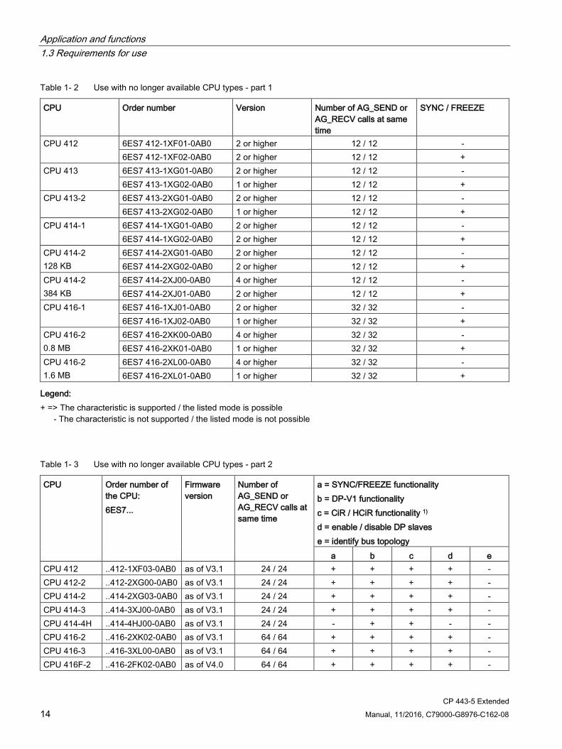
Table 1- 2 Use with no longer available CPU types - part 1
CPU Order number Version Number of AG_SEND or AG_RECV calls at same time
SYNC / FREEZE
CPU 412 6ES7 412-1XF01-0AB0 2 or higher 12 / 12 - 6ES7 412-1XF02-0AB0 2 or higher 12 / 12 +
CPU 413 6ES7 413-1XG01-0AB0 2 or higher 12 / 12 - 6ES7 413-1XG02-0AB0 1 or higher 12 / 12 +
CPU 413-2 6ES7 413-2XG01-0AB0 2 or higher 12 / 12 - 6ES7 413-2XG02-0AB0 1 or higher 12 / 12 +
CPU 414-1 6ES7 414-1XG01-0AB0 2 or higher 12 / 12 - 6ES7 414-1XG02-0AB0 2 or higher 12 / 12 +
CPU 414-2 128 KB
6ES7 414-2XG01-0AB0 2 or higher 12 / 12 - 6ES7 414-2XG02-0AB0 2 or higher 12 / 12 +
CPU 414-2 384 KB
6ES7 414-2XJ00-0AB0 4 or higher 12 / 12 - 6ES7 414-2XJ01-0AB0 2 or higher 12 / 12 +
CPU 416-1 6ES7 416-1XJ01-0AB0 2 or higher 32 / 32 - 6ES7 416-1XJ02-0AB0 1 or higher 32 / 32 +
CPU 416-2 0.8 MB
6ES7 416-2XK00-0AB0 4 or higher 32 / 32 - 6ES7 416-2XK01-0AB0 1 or higher 32 / 32 +
CPU 416-2 1.6 MB
6ES7 416-2XL00-0AB0 4 or higher 32 / 32 - 6ES7 416-2XL01-0AB0 1 or higher 32 / 32 +
Legend: + => The characteristic is supported / the listed mode is possible
- The characteristic is not supported / the listed mode is not possible
Table 1- 3 Use with no longer available CPU types - part 2
CPU Order number of the CPU: 6ES7...
Firmware version
Number of AG_SEND or AG_RECV calls at same time
a = SYNC/FREEZE functionality b = DP-V1 functionality c = CiR / HCiR functionality 1) d = enable / disable DP slaves e = identify bus topology
a b c d e CPU 412 ..412-1XF03-0AB0 as of V3.1 24 / 24 + + + + - CPU 412-2 ..412-2XG00-0AB0 as of V3.1 24 / 24 + + + + - CPU 414-2 ..414-2XG03-0AB0 as of V3.1 24 / 24 + + + + - CPU 414-3 ..414-3XJ00-0AB0 as of V3.1 24 / 24 + + + + - CPU 414-4H ..414-4HJ00-0AB0 as of V3.1 24 / 24 - + + - - CPU 416-2 ..416-2XK02-0AB0 as of V3.1 64 / 64 + + + + - CPU 416-3 ..416-3XL00-0AB0 as of V3.1 64 / 64 + + + + - CPU 416F-2 ..416-2FK02-0AB0 as of V4.0 64 / 64 + + + + -
Application and functions 1.3 Requirements for use
CP 443-5 Extended Manual, 11/2016, C79000-G8976-C162-08 15
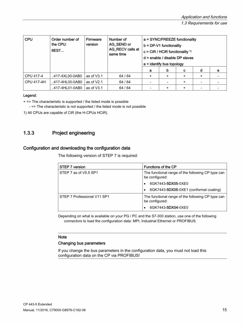
CPU Order number of the CPU: 6ES7...
Firmware version
Number of AG_SEND or AG_RECV calls at same time
a = SYNC/FREEZE functionality b = DP-V1 functionality c = CiR / HCiR functionality 1) d = enable / disable DP slaves e = identify bus topology
a b c d e CPU 417-4 ..417-4XL00-0AB0 as of V3.1 64 / 64 + + + + - CPU 417-4H ..417-4HL00-0AB0 as of V2.1 64 / 64 - - + - -
..417-4HL01-0AB0 as of V3.1 64 / 64 - + + - - Legend:
+ => The characteristic is supported / the listed mode is possible - => The characteristic is not supported / the listed mode is not possible
1) All CPUs are capable of CiR (the H-CPUs HCiR).
1.3.3 Project engineering
Configuration and downloading the configuration data The following version of STEP 7 is required: STEP 7 version Functions of the CP STEP 7 as of V5.5 SP1 The functional range of the following CP type can
be configured: • 6GK7443-5DX05-0XE0 • 6GK7443-5DX05-0XE1 (conformal coating)
STEP 7 Professional V11 SP1 The functional range of the following CP type can be configured: • 6GK7443-5DX04-0XE0
Depending on what is available on your PG / PC and the S7-300 station, use one of the following connectors to load the configuration data: MPI, Industrial Ethernet or PROFIBUS.
Note Changing bus parameters
If you change the bus parameters in the configuration data, you must not load this configuration data on the CP via PROFIBUS!

Application and functions 1.3 Requirements for use
CP 443-5 Extended 16 Manual, 11/2016, C79000-G8976-C162-08
1.3.4 Programming
Program blocks For some communications services of the CP, there are preprogrammed program blocks (FCs / FBs) available as the interface in your STEP 7 user program.
Refer to the documentation of the program blocks in the online help of STEP 7 or in the manual "/7/ (Page 41)".
Note
We recommend that you always use the latest block versions for all module types.
You will find information on the current block versions and the current blocks to download from the Internet in our Customer Support at the following address: Link: (https://support.industry.siemens.com/cs/ww/en/ps/15677/pm)
With older module types, this recommendation assumes that you are using the latest firmware version for the particular module type.
Program blocks for open communications services Program block Meaning AG_SEND (FC5) Send data AG_RECV (FC6) Receive data AG_LSEND (FC50) Send data AG_LRECV (FC60) Receive data
Program blocks for S7 communication Program block Meaning USEND (SFB 8) / URCV (SFB 9) Uncoordinated sending / receipt of data BSEND (SFB 12) / BRCV (SFB 13) Block-oriented sending / receipt of data PUT (SFB 14) / GET (SFB 15) Write data to a remote CPU / read data from a
remote CPU START (SFB 19) / STOP (SFB 20) Run a warm restart / stop on a remote device. RESUME (SFB 21) Run a hot restart on a remote device. STATUS (SFB 22) Query the device status of a remote partner. USTATUS (SFB 23) Receive the status change of a remote device. CONTROL (SFC 62) Query the status of the connection belonging to
an SFB instance.
For more information on the program blocks for S7 communication, see also STEP 7 online help or the manual /8/ (Page 41))

Application and functions 1.4 Performance data
CP 443-5 Extended Manual, 11/2016, C79000-G8976-C162-08 17
1.4 Performance data
1.4.1 Transmission speeds supported The transmission speed is set with the SIMATIC STEP 7 configuration software. For the permitted values, refer to Table 7-1 in Section 7 (Page 33)
Note Remember the cable length
The permitted cable length must be kept to depending on the transmission speed. Refer to the information in /4/ (Page 40)
1.4.2 Characteristic data of the DP interface
General characteristic data No special program blocks are required for DP mode. The interfacing to the distributed I/O is by direct I/O access or using program blocks (SFCs/SFBs) of the CPU (see /4/ (Page 40)).
Table 1- 4 General characteristic data of DP mode
Characteristic Explanation / values Number of operable DP slaves 125 Max. size of the input area of all DP slaves 4 Kbytes Max. size of the output area of all DP slaves 4 Kbytes Maximum number of inputs per DP slave 244 bytes Maximum number of outputs per DP slave 244 bytes Max. size of the consistent area for a module 128 bytes
Application and functions 1.4 Performance data
CP 443-5 Extended 18 Manual, 11/2016, C79000-G8976-C162-08
Diagnostics requests As a DP master (class 1), the CP 4435 supports diagnostics requests of a DP master (class 2).
Note Default value for the startup parameter "Monitoring time for transfer of parameters to modules"
In some situations, it is necessary to increase the default value for the startup parameter "Monitoring time for transfer of parameters to modules" in the Properties dialog of the CPU:
- When there is a large number of modules (DP slaves) configured that can be assigned parameters
- When a high value is configured for the constant bus cycle time in the network properties of the PROFIBUS DP line
CiR functionality The numbers of connections etc. shown in Table General characteristic data of DP mode (Page 17) also apply to the entire DP master system if there is a configured DP slave expansion (CiR functionality).
If you specify the properties of a CiR object in the DP master system of the CP 4435 Extended in STEP 7, these values are included in checks performed by STEP 7.
The configurable properties relate to:
● The number of DP slaves and modules you can insert in a DP slave
● The number of input and output bytes that can still be configured in RUN.
(see also manual /5/ (Page 40))
See also Characteristic data of the DP interface (Page 17)

Application and functions 1.4 Performance data
CP 443-5 Extended Manual, 11/2016, C79000-G8976-C162-08 19
1.4.3 Characteristic data of open communications services (SEND/RECEIVE interface) over FDL connections
General characteristic data The characteristic data is important when operating FDL connections (specified, free layer 2 (SDA and SDN), broadcast, multicast):
Table 1- 5 General characteristic data of open communications services
Characteristic Explanation / values Total number of FDL connections that can be operated.
32 max.
Size of the transferable data area on FDL connections.
1-240 bytes max. per specified FDL connection (for sending and receiving) Free Layer 2, broadcast and multicast: Up to 236 bytes of user data can be transferred per job. The job header occupies an additional 4 bytes.
Cycle load time due to FDL connections The calculation of the cycle load time for FDL connections is largely dependent on the time required to execute the program blocks (AG_SEND, AG_RECV) on the S7400 CPU.
The following table lists the cycle load times of the available FCs in milliseconds. A distinction is made between the statuses "job completed" and "job active". The entries relate to the run time in the CPU 417 (6ES7 417-4XL04-0AB0 - see Table 1-1 Use with the current CPU types (Page 13)).
Table 1- 6 Cycle load time
Job status Job completed Job active Component / FC min. max. min. max. AG_SEND 0.10 ms 0.11 ms 0.14 ms 0.16 ms AG_RECV 0.13 ms 0.14 ms 0.12 ms 0.13 ms
1.4.4 Characteristics of S7 communication
General characteristic data The following information is important when operating S7 connections:
Table 1- 7 General characteristics of S7 connections
Characteristic Explanation / values Number of S7 connections that can be operated via PROFIBUS
48 max. (The value depends on the S7400 CPU being used.)

Application and functions 1.4 Performance data
CP 443-5 Extended 20 Manual, 11/2016, C79000-G8976-C162-08
1.4.5 Parallel use of communications services (multiprotocol mode)
Performance Using the various available communications services at the same time affects communication performance.
To illustrate the relationship between the connection types, the DP mode, and configured connections, the following values apply to the typical configurations: Connection type Number of connections With the DP configuration FDL connections 32 No DP mode
32 With DP mode S7 connections 48 No DP mode
48 With DP mode FDL and S7 connections 1) 59 No DP mode
54 With DP mode 1) one additional S7 connection can be set up online (for example for routing)
Note PG or HMI functions or data record routing
If PG or HMI functions or data record routing are used, a suitable number of S7 connections must be reserved during configuration!
Help provided by STEP 7 The number of connections on PROFIBUS shown in the table above can vary due to other influencing factors. The STEP 7 configuration tool displays warnings and help messages as soon as limit values are exceeded.
Scaling of services in the "mixed mode" The DP delay time is used to scale cyclic DP communication and the other services (FDL and S7 connections). A DP delay time of 0 seconds guarantees the fastest possible DP update. By increasing the DP delay time, you create extra time on the CP for handling other services.
Note Recommendation for mixed mode - PROFIBUS DP along with communications functions
In mixed mode, a delay should be selected as follows: 1 ms at transmission speeds > 1.5 Mbps

Application and functions 1.4 Performance data
CP 443-5 Extended Manual, 11/2016, C79000-G8976-C162-08 21
Note Calling program blocks SFCs and SFBs
For SFCs 11, 12, 13, 51, 55, 56, 57, 58, 59 and 103 as well as SFB 52 and 53, several calls are necessary. The time required to process the job depends on load, round-trip time and transmission speed. If these SFCs are called in a loop within one cycle, the cycle time could be exceeded.
Exceptions: • SFC51 requires only one call if it is used for reading the diagnostics data in a diagnostics
interrupt (SFC51 with parameter 'partial system status list' 0xB1 and 0xB3). • For SFB54 (receive interrupt with SFB54 "RALRM"), only one call is necessary.
Blocks for DPV1 (according to the PNO standard) 1): • SFB52 RDREC "Read data record from a DP slave" corresponds to SFC59 in terms of
function • SFB53 WRREC "Write data record to a DP slave" corresponds to SFC58 in terms of
function • SFB54 ALARM "Read interrupt information from a DP slave" - call in an interrupt OB
1) PNO: PROFIBUS Users Organization
1.4.6 Time-of-day synchronization The CP 4435 forwards timeofday synchronization frames in the following directions:
1. From the CPU via the CP to PROFIBUS if the local CPU is the time master or this station is synchronized via a different LAN and the timeofday synchronization frame is forwarded to PROFIBUS for the synchronization of further stations.
2. From PROFIBUS via the CP to the CPU if a remote station is time master, for example:
– a remote CPU 41x with PROFIBUS interface (for example, CP 4435)
– a remote PC with CP 5412 / 5613 / 5614
Note Transmission speed and synchronization interval
With transmission rates < 1.5 Mbps, we recommend that you configure a synchronization interval of at least 10 s.
1.4.7 Data record routing A maximum of 11 connections can be established simultaneously to PA field devices at any one time.
PDM can, however, use several connections to one PA field device (for more information, refer to the manual /6/ (Page 41)).

Application and functions 1.4 Performance data
CP 443-5 Extended 22 Manual, 11/2016, C79000-G8976-C162-08
1.4.8 Use in fault-tolerant systems With a CP 4435 Extended, you have the following options in a faulttolerant (H) system:
● Operating faulttolerant S7 connections with communications services configured on one partner
or
● You can implement redundant and single peripheral structures (mixed mode is also possible).
You will find more detailed information about the possible operating and structural options in the manual /2/ (Page 40).
If the CP 4435 Extended is used in a faulttolerant S7400H system, the following communications services can also be used on single (nonredundant) connections:
● S7 connection (including PG functions and PG routing)
● S5compatible communication (SEND/RECEIVE interface) on FDL connections
● Forwarding time of day
Note Use in faulttolerant systems 1) Note the CPU types in Table 1-1 Use with the current CPU types (Page 13) / Table 1-2 Use with no longer available CPU types - part 1 (Page 14) / Table 1-3 Use with no longer available CPU types - part 2 (Page 14)
1.4.9 Other characteristics Note on DP:
The connected DP slaves can only be assigned to and serviced by one CPU.
Note CiR functionality - no multicomputing
If you use the CiR functionality, multicomputing is not possible.
Memory reset on the CP
WARNING
Memory reset on the CP
Note that when you reset the CP memory using STEP 7 or STEP 7 special diagnostics, the configuration data on the CPU must also be deleted otherwise the data will become inconsistent.

Application and functions 1.5 Compatibility with previous product
CP 443-5 Extended Manual, 11/2016, C79000-G8976-C162-08 23
Special feature of the DP mode:
If the CPU is in RUN mode at the same time, the memory reset is rejected by the CP.
DP diagnostics frames when the CPU is in STOP All diagnostic frames from DPV0 standard slaves and all DP alarm frames from DP-S7/DP-V1 standard slaves arriving when the CPU is in STOP mode are handled as follows:
● In “S7-compatible" mode
The problems that still exist at the transition from CPU STOP to CPU RUN are passed on the user program.
● In DP-V1 mode
The diagnostics/interrupt frames are forwarded even when the CPU is in STOP mode, however, they must be evaluated by a suitable user program when the module starts up.
1.5 Compatibility with previous product
1.5.1 Extended functionality compared with previous product
Replacing a module The CP (6GK7443-5DX05-0XE0 and 6GK7443-5DX05-0XE1) described here with firmware version V7.0 can be used as a replacement for the following predecessors of the CP 443-5 Extended:
● 6GK7 443-5DX00-0XE0
● 6GK7 443-5DX01-0XE0
● 6GK7 443-5DX02-0XE0
● 6GK7 443-5DX03-0XE0
● 6GK7 443-5DX04-0XE0
Firmware loader - reduced loading time with "FWL_FAST_LOAD" To load new firmware, use only the new function for fast loading.
To do this, select the following entry for the interface parameter assignment of your PC/PG in the firmware loader:
CPxxx(FWL_FAST_LOAD)
By using this function, the time required for loading firmware is reduced significantly compared with the old function.

Application and functions 1.5 Compatibility with previous product
CP 443-5 Extended 24 Manual, 11/2016, C79000-G8976-C162-08
Note CPxxx (FWL) cannot be used
The setting CPxxx(FWL) in the interface parameter assignment cannot be used with this CP type.
Note PROFIBUS
Download the firmware only via the PROFIBUS interface of the CP. To download the firmware, you can use the following: • PROFIBUS connecting cable 6ES7 901-4BD00-0XA0 • PROFIBUS cable with a maximum length of 200 m
The use of an MPI cable is not permitted!
Version history / predecessor products The document “Version History for the SIMATIC NET S7 CPs" contains information on the all the previously supplied PROFIBUS CPs for SIMATIC S7. An up-to-date version of this document is available for downloading on the Internet under the following entry ID:
9836605 (https://support.industry.siemens.com/cs/ww/en/view/67225941)
1.5.2 Replacing older modules / module replacement
Module replacement Please follow the procedure below when replacing an older module with the module described in this document:
Module used up to now Configuration procedure 6GK7 443-5DX00-0XE0 6GK7 443-5DX01-0XE0 6GK7 443-5DX02-0XE0 6GK7 443-5DX03-0XE0 6GK7 443-5DX04-0XE0
Configuration unchanged (replacing a defective module) If you have no requirements beyond what you had with the previous CP, you do not need to make changes in the configuration. All you need to do is replace the hardware with the power supply turned off. Extending the configuration (using new functions) If you want to use options that you had not used with the previous CP, follow the steps below (see also Chapter 3 (Page 27)): 1. In STEP 7, replace the already configured CP 443-5 with the new module; You will
find this in the hardware catalog. 2. Modify your configuration according to your requirements, for example in the Prop-
erties dialog for the PROFIBUS subnet. 3. Save, compile and load the configuration data to the CPU or CP again.

CP 443-5 Extended Manual, 11/2016, C79000-G8976-C162-08 25
Displays and mode selector 2
LED display of the operating status of the CP
The different combinations of the five LEDs on the front panel indicate the status of the CP:
Table 2- 1 Legend - meaning of the symbols:
Symbol
-
Status ON (steady light) OFF Flashing Any
INTF LED EXTF LED BUSF LED RUN LED STOP LED CP operating mode
- - -
Starting up (STOP->RUN)
- - -
Running (RUN)
- - -
Stopping (RUN->STOP)
- - -
Stopped (STOP)
- -
STOP with internal error or memory reset.
Waiting for firmware update (duration 10 sec-onds after power on)
Waiting for firmware update (CP currently has an incomplete firmware version)
Firmware update completed. (As of firmware version V7.1.7)

Displays and mode selector
CP 443-5 Extended 26 Manual, 11/2016, C79000-G8976-C162-08
INTF LED EXTF LED BUSF LED RUN LED STOP LED CP operating mode
- -
• Download in RUN active / CiR • RUN with internal error (for example, bad
configuration data)
- -
- - PROFIBUS bus error
-
RUN; however problems on DP line (DP slave not in data transfer or not accessible)
-
RUN; however problems on DP line (faulty module in DP slave)
Module fault / system error Note: For service purposes, you can read out the cause of the operating status from the diagnos-tics buffer of the CP. To do this, the CP needs to be changed from STOP to RUN using the mode selector.
Controlling the mode There are different ways in which you can control the mode of the CP 443-5 Extended, as follows:
● Mode selector
● STEP 7 special diagnostics configuration software
To control the CP mode from STEP 7, the mode selector must be set to RUN.
Mode selector With the mode selector, you can set the following modes:
● Change from STOP to RUN:
The CP loads configured and/or downloaded data into the work memory and then changes to RUN mode.
● Change from RUN to STOP:
The CP changes to STOP with the following response:
– Established connections (FDL connections, configured, and unconfigured S7 connections) are terminated
– DP slaves are taken out of data transfer
– Data record routing is deactivated
– In STOP mode, configuring and performing diagnostics on the CP remain possible
– In STOP mode, the time of day continues to be forwarded

CP 443-5 Extended Manual, 11/2016, C79000-G8976-C162-08 27
Installation and commissioning 3 Safety notices on the use of the device
The following safety notices must be adhered to when setting up and operating the device and during all associated work such as installation, connecting up, replacing devices or opening the device.
3.1 Notes on use in hazardous areas
WARNING
EXPLOSION HAZARD
Do not open the device when the supply voltage is turned on.
WARNING
The device may only be operated in an environment with pollution degree 1 or 2 (see IEC 60664-1).
WARNING
The equipment is designed for operation with Safety Extra-Low Voltage (SELV) by a Limited Power Source (LPS).
This means that only SELV / LPS complying with IEC 60950-1 / EN 60950-1 / VDE 0805-1 must be connected to the power supply terminals. The power supply unit for the equipment power supply must comply with NEC Class 2, as described by the National Electrical Code (r) (ANSI / NFPA 70).
If the equipment is connected to a redundant power supply (two separate power supplies), both must meet these requirements.
WARNING
EXPLOSION HAZARD
Do not connect or disconnect cables to or from the device when a flammable or combustible atmosphere is present.

Installation and commissioning 3.2 Notes on use in hazardous areas according to ATEX / IECEx
CP 443-5 Extended 28 Manual, 11/2016, C79000-G8976-C162-08
WARNING
EXPLOSION HAZARD
Replacing components may impair suitability for Class 1, Division 2 or Zone 2.
WARNING
When used in hazardous environments corresponding to Class I, Division 2 or Class I, Zone 2, the device must be installed in a cabinet or a suitable enclosure.
3.2 Notes on use in hazardous areas according to ATEX / IECEx
WARNING
DIN rail
In the ATEX and IECEx area of application only the Siemens DIN rail 6ES5 710-8MA11 may be used to mount the modules.
WARNING
Requirements for the cabinet/enclosure
To comply with EU Directive 94/9 (ATEX95), the enclosure or cabinet must meet the requirements of at least IP54 in compliance with EN 60529.
WARNING
Cable
If the cable or conduit entry point exceeds 70 °C or the branching point of conductors exceeds 80 °C, special precautions must be taken. If the equipment is operated in an air ambient in excess of 50 °C, only use cables with admitted maximum operating temperature of at least 80 °C.
WARNING
Take measures to prevent transient voltage surges of more than 40% of the rated voltage. This is the case if you only operate devices with SELV (safety extra-low voltage).

Installation and commissioning 3.3 Notes on use in hazardous areas according to UL HazLoc
CP 443-5 Extended Manual, 11/2016, C79000-G8976-C162-08 29
3.3 Notes on use in hazardous areas according to UL HazLoc
WARNING
EXPLOSION HAZARD
Do not connect or disconnect while the circuit is live or unless the area is known to be free of ignitible concentrations.
This equipment is suitable for use in Class I, Division 2, Groups A, B, C and D or non-hazardous locations only.
This equipment is suitable for use in Class I, Zone 2, Group IIC or non-hazardous locations only.
3.4 Installation and commissioning
NOTICE
Do not pull or plug the CP while power is on
The CP 443-5 Extended must not be pulled or plugged while the power is connected. In some cases, this could lead to damage of the module.
If you do pull or plug the CP while power is on, the CPU changes to STOP.
Afterwards, the power for the central rack must be cycled.
Keep to the installation guide for SIMATIC S7-400 During installation, keep to the guidelines and instructions in the following documents:
● S7-400 installation manual /3/ (Page 40)
● SIMATIC NET PROFIBUS network manual /4/ (Page 40)
Installation and commissioning 3.4 Installation and commissioning
CP 443-5 Extended 30 Manual, 11/2016, C79000-G8976-C162-08
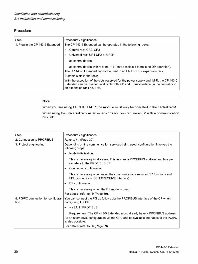
Procedure Step Procedure / significance 1. Plug in the CP 443-5 Extended The CP 443-5 Extended can be operated in the following racks:
• Central rack CR2, CR3 • Universal rack UR1 UR2 or UR2H
as central device
as central device with rack no. 1-6 (only possible if there is no DP operation). The CP 443-5 Extended cannot be used in an ER1 or ER2 expansion rack. Suitable slots in the rack: With the exception of the slots reserved for the power supply and IM-R, the CP 443-5 Extended can be inserted in all slots with a P and K bus interface (in the central or in an expansion rack no. 1-6).
Note
When you are using PROFIBUS-DP, the module must only be operated in the central rack!
When using the universal rack as an extension rack, you require an IM with a communication bus link!
Step Procedure / significance 2. Connection to PROFIBUS Refer to /1/ (Page 39). 3. Project engineering Depending on the communication services being used, configuration involves the
following steps: • Node initialization
This is necessary in all cases. This assigns a PROFIBUS address and bus pa-rameters to the PROFIBUS CP.
• Connection configuration
This is necessary when using the communications services, S7 functions and FDL connections (SEND/RECEIVE interface).
• DP configuration
This is necessary when the DP mode is used. For details, refer to /1/ (Page 39).
4. PG/PC connection for configura-tion
You can connect the PG as follows via the PROFIBUS interface of the CP when configuring the CP: • via LAN / PROFIBUS
Requirement: The CP 443-5 Extended must already have a PROFIBUS address. As an alternative, configuration via the CPU and its available interfaces to the PG/PC is also possible. For details, refer to /1/ (Page 39).
CP 443-5 Extended Manual, 11/2016, C79000-G8976-C162-08 31
Notes on operation 4 4.1 General operation on PROFIBUS
Disruptions with modified transmission speed If you modify the transmission speed when downloading the configuration, the CP 443-5 Extended sporadically remains in the "stopping" mode.
In such cases, a memory reset of the S7 station is necessary.
Follow the steps outlined below:
1. Run a memory reset on the S7 station (CPU)
To reset memory, use the corresponding function in the configuration tool.
2. Turn the power supply to the S7 station on and off again.
Bus fault of the type "bus short-circuit" If there is a bus short-circuit, this can cause one of the following responses on the PROFIBUS subnet:
● Failure of the bus line
● Failure of stations / of all stations
The response can be recognized by evaluating with OB86.
Note Bus fault statistics
With STEP 7 special diagnostics, you can read out the information from the entry PROFIBUS > Statistics > Bus fault statistics If there is a bus fault, it is possible that different bus fault events are registered in the statistics even though it appears that identical bus faults have occurred.
4.2 Display "Existing channel error" in the diagnostics interrupt OB (OB82)
Display "Existing channel error" in the diagnostics interrupt OB (OB82) Under certain circumstances, the "Existing channel error" flag may not be set (false) although there is a channel error.

Notes on operation 4.3 Display of the the DP slave history
CP 443-5 Extended 32 Manual, 11/2016, C79000-G8976-C162-08
This reaction corresponds to the current response on the PROFIBUS interfaces with SIMATIC.
Remedy: You can read out detailed up-to-date diagnostics information using the diagnostics function "Read system diagnostics" SFC13 (read out standard diagnostics).
4.3 Display of the the DP slave history
Restricted display of older diagnostics data in STEP 7 special diagnostics Diagnostics data can be read out in STEP 7 special diagnostics. With an additional button, you can also have older diagnostics data displayed alongside the current diagnostics data.
With the CP 443-5 Extended (DX05), it is possible that not all the older diagnostics events can be displayed due to the limited buffer size - the display of underlying intermediate states is then omitted.
4.4 Other information available about the CP
FAQs on the Internet You will find detailed information (FAQs) on using the PROFIBUS S7-CPs at the following Internet address (entry type: FAQ):
Link: (https://support.industry.siemens.com/cs/ww/en/ps/15677/faq)

CP 443-5 Extended Manual, 11/2016, C79000-G8976-C162-08 33
Technical specifications 5
General technical specifications
Technical specifications Value Transmission speeds supported 9.6 kbps, 19.2 kbps, 45.45 kbps
93.75 kbps, 187.5 kbps, 500 kbps 1.5 Mbps, 3 Mbps, 6 Mbps, 12 Mbps
Interfaces • Connection to PROFIBUS
1 x 9-pin D-sub female connector (RS-485)
Maximum current consumption on the PROFIBUS interface when connecting network components (for example optical network components)
100 mA at 5 V
Supply voltage from backplane bus (rated voltage) 5 V DC Current consumption From the S7-400 backplane bus
0.6 A typical at 5 V
Power dissipation 3 W Permitted ambient conditions • Operating temperature • Transport/storage temperature • Relative humidity • Operating altitude
• 0 °C to +60 °C • -40 °C to +70 °C • maximum 95% at +25 °C up to 2000 m above sea level
Degree of protection IP 20 Construction Dimensions W x H x D (mm)
25 x 290 x 210
Weight Approx. 650 g
In addition to this, all the information in the S7-400/M7-400 reference manual "Module Data" /3/ (Page 40) in the section "General Technical Specifications" on the topics listed below applies to the CP 443-5 Extended.
● Electromagnetic compatibility
● Transportation/storage conditions
● Mechanical and climatic environmental conditions
● Information on insulation checks, protection class and degree of protection

Technical specifications
CP 443-5 Extended 34 Manual, 11/2016, C79000-G8976-C162-08

CP 443-5 Extended Manual, 11/2016, C79000-G8976-C162-08 35
Approvals A
Approvals issued
Note Issued approvals on the type plate of the device
The specified approvals apply only when the corresponding mark is printed on the product. You can check which of the following approvals have been granted for your product by the markings on the type plate.
Approvals for shipbuilding are not printed on the device type plate.
EC declaration of conformity The CP meets the requirements and safety objectives of the following EU directives and it complies with the harmonized European standards (EN) for programmable logic controllers which are published in the official documentation of the European Union.
● 2014/34/EU (ATEX explosion protection directive)
Directive of the European Parliament and the Council of 26 February 2014 on the approximation of the laws of the member states concerning equipment and protective systems intended for use in potentially explosive atmospheres, official journal of the EU L96, 29/03/2014, pages. 309-356
● 2014/30/EU (EMC)
EMC directive of the European Parliament and of the Council of February 26, 2014 on the approximation of the laws of the member states relating to electromagnetic compatibility; official journal of the EU L96, 29/03/2014, pages. 79-106
● 2011/65/EU (RoHS)
Directive of the European Parliament and of the Council of 8 June 2011 on the restriction of the use of certain hazardous substances in electrical and electronic equipment
● IEC 61131-2
The EC Declaration of Conformity is available for all responsible authorities at:
Siemens Aktiengesellschaft Division Process Industries and Drives Process Automation DE-76181 Karlsruhe Germany
You will find the EC Declaration of Conformity on the Internet at the following address:
Link: (https://support.industry.siemens.com/cs/ww/en/ps/15679/cert)
● Entry type: "Certificates"
● Certificate type: "Declaration of conformity"
Approvals
CP 443-5 Extended 36 Manual, 11/2016, C79000-G8976-C162-08
WARNING
Information on standards and approvals
Before you put the device into operation, read the information on standards and approvals in Part A of this manual /3/ (Page 40).
The CP has the following approvals or conforms to the following directives:
IECEx The CP meet the requirements of explosion protection according to IECEx.
IECEx certificate: IECEx DEK 14.0034X
The CP meets the requirements of the following standards:
● IEC 60079-0
Hazardous areas - Part 0: Equipment - General requirements
● EN 60079-15
Explosive atmospheres - Part 15: Equipment protection by type of protection 'n'
You can see the current versions of the standards in the IECEx certificate that you will find on the Internet at the following address:
Link: (https://support.industry.siemens.com/cs/ww/en/ps/15679/cert)
The conditions must be met for the safe deployment of the CP according to the section Notes on use in hazardous areas according to ATEX / IECEx (Page 28).
You should also note the information in the document "Use of subassemblies/modules in a Zone 2 Hazardous Area" that you will find on the Internet at the following address:
Link: (https://support.industry.siemens.com/cs/ww/en/view/78381013)
ATEX The CP meets the requirements of the EC directive 2014/34/EU "Equipment and Protective Devices for Use in Potentially Explosive Atmospheres".
Applied standards:
● EN 60079-0
Hazardous areas - Part 0: Equipment - General requirements
● EN 60079-15
Explosive atmospheres - Part 15: Equipment protection by type of protection 'n'
The current versions of the standards can be seen in the EC Declaration of Conformity, see above.
ATEX approval: II 3 G Ex nA IIC T4 Gc
Test number: KEMA 03 ATEX1125 X

Approvals
CP 443-5 Extended Manual, 11/2016, C79000-G8976-C162-08 37
The conditions must be met for the safe deployment of the CP according to the section Notes on use in hazardous areas according to ATEX / IECEx (Page 28).
You should also note the information in the document "Use of subassemblies/modules in a Zone 2 Hazardous Area" that you will find on the Internet at the following address:
Link: (https://support.industry.siemens.com/cs/ww/en/view/78381013)
EMC Until 19.04.2016 the CP meets the requirements of the EC Directive 2014/30/EU "Electromagnetic Compatibility” (EMC directive).
Applied standards:
● EN 61000-6-4
Electromagnetic compatibility (EMC) - Part 6-4: Generic standards - Emission standard for industrial environments
● EN 61000-6-2
Electromagnetic compatibility (EMC) - Part 6-2: Generic standards - Immunity for industrial environments
RoHS The CP meets the requirements of the EC directive 2011/65/EU on the restriction of the use of certain hazardous substances in electrical and electronic equipment.
Applied standard:
● EN 50581:2012
c(UL)us Applied standards:
● Underwriters Laboratories, Inc.: UL 61010-1 (Safety Requirements for Electrical Equipment for Measurement, Control, and Laboratory Use - Part 1: General Requirements)
● IEC/UL 61010-2-201 (Safety requirements for electrical equipment for measurement, control and laboratory use. Particular requirements for control equipment)
● Canadian Standards Association: CSA C22.2 No. 142 (Process Control Equipment)
Report / UL file: E85972 (NRAG, NRAG7)
cULus Hazardous (Classified) Locations Underwriters Laboratories, Inc.: cULus IND. CONT. EQ. FOR HAZ. LOC.
Applied standards:
● ANSI ISA 12.12.01
● CSA C22.2 No. 213-M1987

Approvals
CP 443-5 Extended 38 Manual, 11/2016, C79000-G8976-C162-08
APPROVED for Use in:
● Cl. 1, Div. 2, GP. A, B, C, D T4
● Cl. 1, Zone 2, GP. IIC T4
Ta: Refer to the temperature class on the type plate of the CP
Report / UL file: E223122 (NRAG, NRAG7)
Note the conditions for the safe deployment of the CP according to the section Notes on use in hazardous areas according to UL HazLoc (Page 29).
Current approvals SIMATIC NET products are regularly submitted to the relevant authorities and approval centers for approvals relating to specific markets and applications.
If you require a list of the current approvals for individual devices, consult your Siemens contact or check the Internet pages of Siemens Industry Online Support:
Link: (https://support.industry.siemens.com/cs/ww/en/ps/15679/cert)

CP 443-5 Extended Manual, 11/2016, C79000-G8976-C162-08 39
References B
Where to find Siemens documentation ● Article numbers
You will find the article numbers for the Siemens products of relevance here in the following catalogs:
– SIMATIC NET - Industrial Communication / Industrial Identification, catalog IK PI
– SIMATIC - Products for Totally Integrated Automation and Micro Automation, catalog ST 70
You can request the catalogs and additional information from your Siemens representative. You will also find the product information in the Siemens Industry Mall at the following address:
Link: (https://mall.industry.siemens.com)
● Manuals on the Internet
You will find SIMATIC NET manuals on the Internet pages of Siemens Industry Online Support:
Link: (https://support.industry.siemens.com/cs/ww/en/ps/15661/man)
Go to the required product in the product tree and make the following settings:
Entry type “Manuals”
● Manuals on the data medium
You will find manuals of SIMATIC NET products on the data medium that ships with many of the SIMATIC NET products.
B.1 On configuring and using the CP
/1/ SIMATIC NET S7 CPs for PROFIBUS Configuring and Commissioning Manual Part A - General Applications configuration manual Siemens AG (SIMATIC NET Manual Collection) 1158693 (https://support.industry.siemens.com/cs/ww/en/view/1158693)

References B.2 On installing and commissioning the CP
CP 443-5 Extended 40 Manual, 11/2016, C79000-G8976-C162-08
/2/ SIMATIC Fault-tolerant Systems S7-400H Manual Siemens AG 1186523 (https://support.industry.siemens.com/cs/ww/en/view/1186523)
B.2 On installing and commissioning the CP
/3/ SIMATIC S7 Siemens AG
● S7-300 automation system
– CPU 31xC and 31x Installation: Operating Instructions Link: Link: (https://support.industry.siemens.com/cs/ww/en/view/13008499)
– Module Data: Reference Manual Link: Link: (https://support.industry.siemens.com/cs/ww/en/view/8859629)
● Automation system S7-400, M7-400
– Installation: Installation Manual Link: Link: (https://support.industry.siemens.com/cs/ww/en/view/1117849)
– Module Data: Reference Manual Link: Link: (https://support.industry.siemens.com/cs/ww/en/view/1117740)
/4/ SIMATIC NET PROFIBUS Network Manual Siemens AG (SIMATIC NET Manual Collection) Link: (https://support.industry.siemens.com/cs/ww/en/view/35222591)
/5/ SIMATIC Modifying the System during Operation via CiR Manual Siemens AG Link: (https://support.industry.siemens.com/cs/ww/en/view/45531308)

References B.3 On programming
CP 443-5 Extended Manual, 11/2016, C79000-G8976-C162-08 41
/6/ SIMATIC The Process Device Manager Manual Siemens AG Link: (https://support.industry.siemens.com/cs/ww/en/view/21407212)
B.3 On programming
/7/ SIMATIC NET Program blocks for SIMATIC NET S7 CPs Programming Manual Siemens AG Link: (https://support.industry.siemens.com/cs/ww/en/view/62543517)
/8/ SIMATIC System and Standard Functions for S7-300/400 - Volume 1/2 Reference manual Siemens AG (Part of the STEP 7 documentation package STEP 7 Basic Knowledge) (Part of the online documentation in STEP 7) Link: (https://support.industry.siemens.com/cs/ww/en/view/1214574)

References B.3 On programming
CP 443-5 Extended 42 Manual, 11/2016, C79000-G8976-C162-08

CP 443-5 Extended Manual, 11/2016, C79000-G8976-C162-08 43
Index
A Automation system, 9
B Backplane bus, 33 Battery backup, 11 Broadcast, 10 Bus fault, 31 Bus fault statistics, 31 Bus parameter
Changing, 15 Bus short-circuit, 31 Bus topology, 10, 12, 13
C Cable length, 17 Channel error
Display, 31 Characteristic data, 17, 19, 19 CiR, 10, 12, 13, 18, 22 Compatibility with predecessor versions, 4 Configuration limits, 12 Connection to PROFIBUS, 30 Constant bus cycle time mode, 9 CPU operating system, 11 CPU type, 12 Current consumption, 33 Cycle load time due to FDL connections, 19
D Data record routing, 11, 26 Degree of protection, 33, 33 Diagnostics data
Display of older, 32 Diagnostics requests, 10, 18 Direct data exchange, 9 DP diagnostics frames when the CPU is in STOP, 23 DP master (class 1), 9 DP slave, 10
Activate/deactivate, 12 DPV1, 23
DPV1 functionality, 12, 13
E Electromagnetic compatibility, 33 Environmental conditions, 33 ET 200M I/O devices, 12
F FAQs on the Internet, 32 FDL connections, 10 Field device, 9 Firmware
Loading time, 23 Firmware version, 3 Flash memory card, 11 FM modules, 11 Forwarding time of day, 26 Free layer 2 connections, 10
G Glossary, 5
H H system, 9, 22 Hardware product version, 3 HCiR, 15 HMI, 11
I Installation guide, 29 Insulation tests, 33 Interfaces, 33
M Manual Part A, 4 Manual Part B, 4 Memory reset, 22, 31 Mixed mode, 20, 22 Mode selector, 26

Index
CP 443-5 Extended 44 Manual, 11/2016, C79000-G8976-C162-08
Module replacement, 24 MPI cable, 24 Multicast, 10 Multicomputing, 12, 13, 22
O Open communications services, 10, 16 Operating mode, 25 Order number, 12
P PA field device, 21 PA slave, 9 PDM, 21 Performance, 20 PG/OP communication, 11 PG/PC connection for configuration, 30 Power dissipation, 33 PROFIBUS connecting cable, 24 PROFIBUS DP, 9 Program blocks, 16, 21 Project engineering, 24, 30
Via the CPU, 30 Protection class, 33
R Replacing a module, 23, 24 Replacing a module without a programming device, 11 Router, 9 Routing, 11 RUN, 23, 26
S S7 communication, 11, 16 S7 connections, 11, 19 Safety notices, 27 SEND/RECEIVE interface, 12 SIMATIC NET glossary, 5 Slot, 30 Special diagnostics, 26, 32 Startup parameters, 18 STEP 7, 4 STEP 7 Professional, 15 STEP 7 V5.5, 15 STOP, 23, 26 SYNC / FREEZE, 9, 12
Synchronization interval, 21 System environment, 12
T Technical specifications, 33 Time-of-day synchronization, 11 Timeofday synchronization frames, Transmission speed, 17, 21
Disruptions with modified, 31 Transmission speeds, 33 Transportation/storage conditions, 33
V Version, 12 Version history, 24
W Weight, 33