Scheme & Syllabi of M.Tech Course in Digital signal processing
Course Structure and Syllabi for
Two Year M.Tech. (Power Systems with emphasis on
HV Engineering)(w. e. f. the batch admitted
in the Academic year 2009 – 2010)
Department of Electrical & Electronics
Engg.
JNTU COLLEGE OF ENGINEERING : : KAKINADAA N D H R A P R A D E S H
DEPARTMENT OF ELECTRICAL & ELECTRONICS ENGINEERING
1
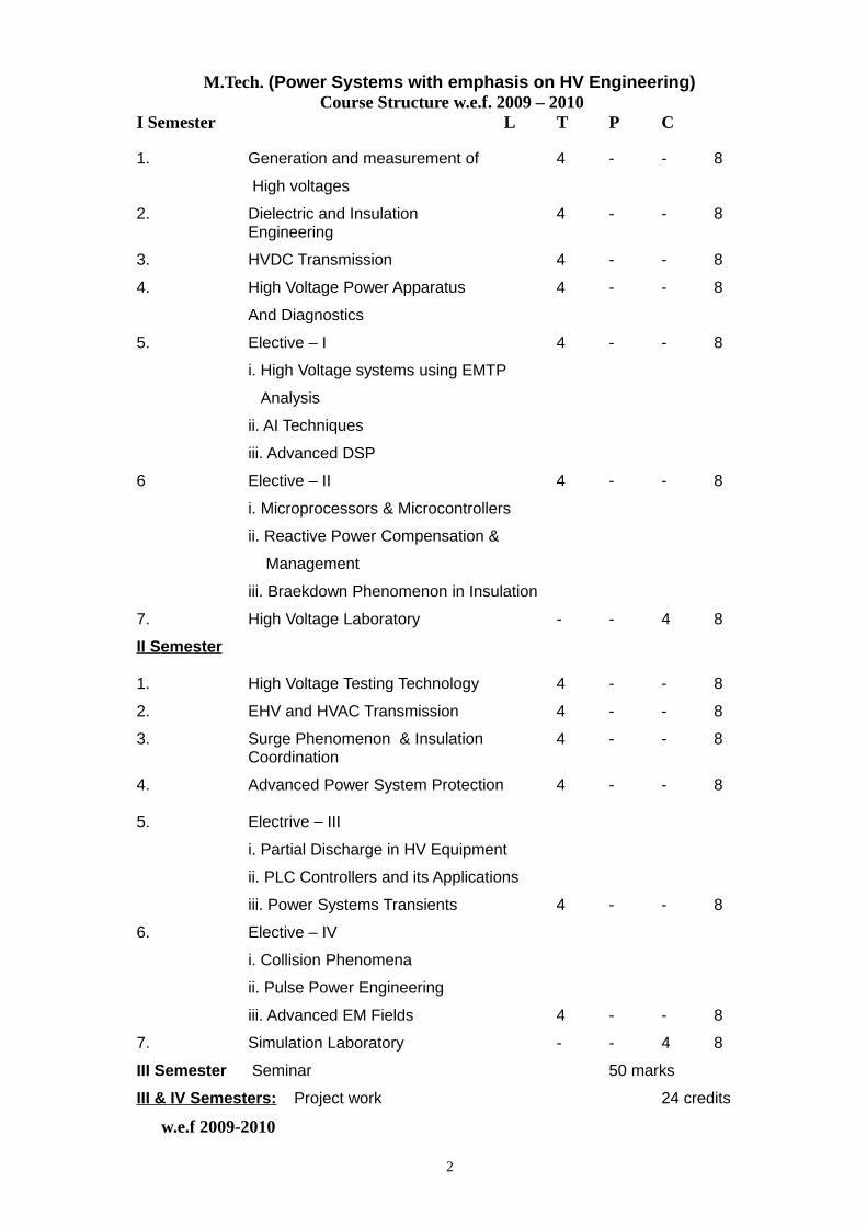
M.Tech. (Power Systems with emphasis on HV Engineering) Course Structure w.e.f. 2009 – 2010
I Semester L T P C
1. Generation and measurement of 4 - - 8
High voltages
2. Dielectric and Insulation 4 - - 8Engineering
3. HVDC Transmission 4 - - 8
4. High Voltage Power Apparatus 4 - - 8
And Diagnostics
5. Elective – I 4 - - 8
i. High Voltage systems using EMTP
Analysis
ii. AI Techniques
iii. Advanced DSP
6 Elective – II 4 - - 8
i. Microprocessors & Microcontrollers
ii. Reactive Power Compensation &
Management
iii. Braekdown Phenomenon in Insulation
7. High Voltage Laboratory - - 4 8
II Semester
1. High Voltage Testing Technology 4 - - 8
2. EHV and HVAC Transmission 4 - - 8
3. Surge Phenomenon & Insulation 4 - - 8Coordination
4. Advanced Power System Protection 4 - - 8
5. Electrive – III
i. Partial Discharge in HV Equipment
ii. PLC Controllers and its Applications
iii. Power Systems Transients 4 - - 8
6. Elective – IV
i. Collision Phenomena
ii. Pulse Power Engineering
iii. Advanced EM Fields 4 - - 8
7. Simulation Laboratory - - 4 8
III Semester Seminar 50 marks
III & IV Semesters: Project work 24 credits
w.e.f 2009-2010
2
JAWAHARLAL NEHRU TECHNOLOGICAL UNIVERSITY: KAKINADADEPARTMENT OF ELECTRICAL AND ELECTRONICS ENGINEERING
(POWER SYSTEM WITH EMPAHSIS ON HV ENGINEERING)M. Tech- I Semester
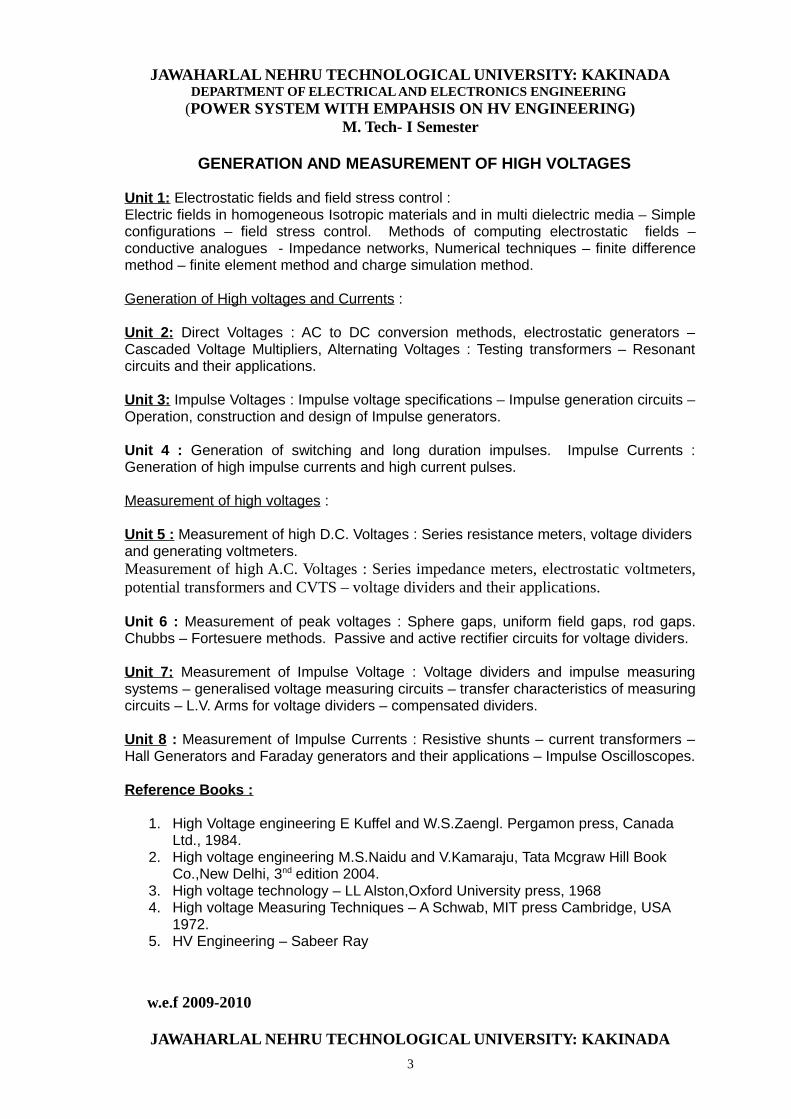
GENERATION AND MEASUREMENT OF HIGH VOLTAGES
Unit 1: Electrostatic fields and field stress control :Electric fields in homogeneous Isotropic materials and in multi dielectric media – Simpleconfigurations – field stress control. Methods of computing electrostatic fields –conductive analogues - Impedance networks, Numerical techniques – finite differencemethod – finite element method and charge simulation method.
Generation of High voltages and Currents :
Unit 2: Direct Voltages : AC to DC conversion methods, electrostatic generators –Cascaded Voltage Multipliers, Alternating Voltages : Testing transformers – Resonantcircuits and their applications.
Unit 3: Impulse Voltages : Impulse voltage specifications – Impulse generation circuits –Operation, construction and design of Impulse generators.
Unit 4 : Generation of switching and long duration impulses. Impulse Currents :Generation of high impulse currents and high current pulses.
Measurement of high voltages :
Unit 5 : Measurement of high D.C. Voltages : Series resistance meters, voltage dividersand generating voltmeters.Measurement of high A.C. Voltages : Series impedance meters, electrostatic voltmeters,potential transformers and CVTS – voltage dividers and their applications.
Unit 6 : Measurement of peak voltages : Sphere gaps, uniform field gaps, rod gaps.Chubbs – Fortesuere methods. Passive and active rectifier circuits for voltage dividers.
Unit 7: Measurement of Impulse Voltage : Voltage dividers and impulse measuringsystems – generalised voltage measuring circuits – transfer characteristics of measuringcircuits – L.V. Arms for voltage dividers – compensated dividers.
Unit 8 : Measurement of Impulse Currents : Resistive shunts – current transformers –Hall Generators and Faraday generators and their applications – Impulse Oscilloscopes.
Reference Books :
1. High Voltage engineering E Kuffel and W.S.Zaengl. Pergamon press, Canada Ltd., 1984.
2. High voltage engineering M.S.Naidu and V.Kamaraju, Tata Mcgraw Hill Book Co.,New Delhi, 3nd edition 2004.
3. High voltage technology – LL Alston,Oxford University press, 19684. High voltage Measuring Techniques – A Schwab, MIT press Cambridge, USA
1972. 5. HV Engineering – Sabeer Ray
w.e.f 2009-2010
JAWAHARLAL NEHRU TECHNOLOGICAL UNIVERSITY: KAKINADA
3
DEPARTMENT OF ELECTRICAL AND ELECTRONICS ENGINEERING (POWER SYSTEM WITH EMPAHSIS ON HV ENGINEERING)
M. Tech- I Semester
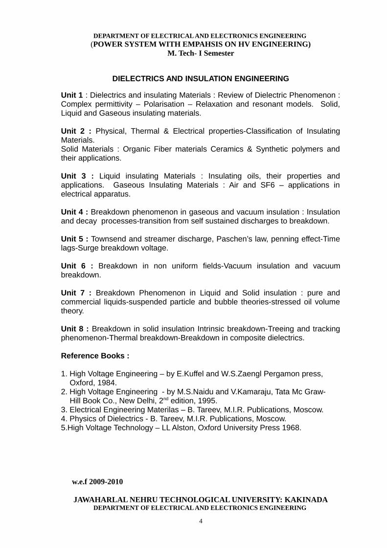
DIELECTRICS AND INSULATION ENGINEERING
Unit 1 : Dielectrics and insulating Materials : Review of Dielectric Phenomenon :Complex permittivity – Polarisation – Relaxation and resonant models. Solid,Liquid and Gaseous insulating materials.
Unit 2 : Physical, Thermal & Electrical properties-Classification of InsulatingMaterials.Solid Materials : Organic Fiber materials Ceramics & Synthetic polymers andtheir applications.
Unit 3 : Liquid insulating Materials : Insulating oils, their properties andapplications. Gaseous Insulating Materials : Air and SF6 – applications inelectrical apparatus.
Unit 4 : Breakdown phenomenon in gaseous and vacuum insulation : Insulationand decay processes-transition from self sustained discharges to breakdown.
Unit 5 : Townsend and streamer discharge, Paschen’s law, penning effect-Timelags-Surge breakdown voltage.
Unit 6 : Breakdown in non uniform fields-Vacuum insulation and vacuumbreakdown.
Unit 7 : Breakdown Phenomenon in Liquid and Solid insulation : pure andcommercial liquids-suspended particle and bubble theories-stressed oil volumetheory.
Unit 8 : Breakdown in solid insulation Intrinsic breakdown-Treeing and trackingphenomenon-Thermal breakdown-Breakdown in composite dielectrics.
Reference Books :
1. High Voltage Engineering – by E.Kuffel and W.S.Zaengl Pergamon press, Oxford, 1984.2. High Voltage Engineering - by M.S.Naidu and V.Kamaraju, Tata Mc Graw- Hill Book Co., New Delhi, 2nd edition, 1995.3. Electrical Engineering Materilas – B. Tareev, M.I.R. Publications, Moscow.4. Physics of Dielectrics - B. Tareev, M.I.R. Publications, Moscow.5.High Voltage Technology – LL Alston, Oxford University Press 1968.
w.e.f 2009-2010
JAWAHARLAL NEHRU TECHNOLOGICAL UNIVERSITY: KAKINADADEPARTMENT OF ELECTRICAL AND ELECTRONICS ENGINEERING
4
(POWER SYSTEM WITH EMPAHSIS ON HV ENGINEERING)M. Tech- I Semester
H.V.D.C. TRANSMISSION
Unit 1 :H.V.D.C. Transmission : General considerations, Power HandlingCapabilities of HVDC Lines, Basic Conversion principles, static converterconfiguration.
Unit 2 : Static Power Converters : 3-pulse, 6-pulse and 12-pulse converters,converter station and Terminal equipment, commutation process, Rectifier andinverter operation, equivalent circuit for converter – special features of convertertransformers.
Unit 3 : Harmonics in HVDC Systems, Harmonic elimination, AC and DC filters.
Unit 4 : Control of HVDC Converters and systems : constant current, constantextinction angle and constant Ignition angle control. Individual phase control andequidistant firing angle control, DC power flow control.
Unit 5 : Interaction between HV AC and DC systems – Voltage interaction,Harmonic instability problems and DC power modulation.
Unit 6 : Multi-terminal DC links and systems; series, parallel and series parallelsystems, their operation and control.
Unit 7 : Transient over voltages in HV DC systems : Over voltages due todisturbances on DC side, over voltages due to DC and AC side line faults
Unit 8:Converter faults and protection in HVDC Systems: Converter faults, overcurrent protection - valve group, and DC line protection, circuit breakers. Overvoltage protection of converters, surge arresters.
Reference Books :
1. K.R.Padiyar : High Voltage Direct current Transmission, Wiley Eastern Ltd., New Delhi – 1992.
2. E.W. Kimbark : Direct current Transmission, Wiley Inter Science – New York.
3. J.Arillaga : H.V.D.C.Transmission Peter Peregrinus ltd., London UK 1983
4. E.Uhlman : Power Transmission by Direct Current, Springer Verlag, BerlinHelberg – 1985.
w.e.f 2009-2010
JAWAHARLAL NEHRU TECHNOLOGICAL UNIVERSITY: KAKINADADEPARTMENT OF ELECTRICAL AND ELECTRONICS ENGINEERING
5
(POWER SYSTEM WITH EMPAHSIS ON HV ENGINEERING)M. Tech- I Semester
HIGH VOLTAGE POWER APPARATUS AND DIAGNOSTICS
w.e.f 2009-2010
JAWAHARLAL NEHRU TECHNOLOGICAL UNIVERSITY: KAKINADADEPARTMENT OF ELECTRICAL AND ELECTRONICS ENGINEERING
6
(POWER SYSTEM WITH EMPAHSIS ON HV ENGINEERING)M. Tech- I Semester
HIGH VOLTAGE SYSTEMS USING EMTP ANALYSIS(Elective-I)
UNIT-1 Definitions, objectives and background Introduction ,Classification of electromagnetic transients , Transientsimulators , Digital simulation -State variable analysis and Method ofdifference equations , Range of applications. UNIT- 2 Analysis of continuous and discrete systems Continuous systems - State variable formulations, -Successivedifferentiation, - Controller canonical form, -Observer canonical form,-Diagonal canonical form, -Uniqueness of formulation , Time domainsolution of state equations , Digital simulation of continuous systems,Discrete systems, Relationship of continuous and discrete domains.UNIT-3 State variable analysis Choice of state variables, Formation of the state equations - Thetransform method , The graph method, Solution procedure..UNIT-4 Numerical integrator for linear parametersDiscretisation of R, L, C elements - Resistance , -Inductance ,-Capacitance, -Components reduction, Dual Norton model of thetransmission line , Network solution,Step Response for RL and RC loads.UNIT-5 Numerical integrator for nonlinear parameters Non-linear or time varying parameters -Current sourcerepresentation , -Compensation method , -Piecewise linear method .UNIT-6 The root-matching method Exponential form of the difference equation , z-domain representationof difference equations, Implementation in EMTP algorithm , Family ofexponential forms of the difference equation -Step response , -Steady-state response , -Frequency response.UNIT-7 Transmission lines and cables Bergeron’s model - Multiconductor transmission lines , Frequency-dependent transmission lines-Frequency to time domaintransformation and Phase domain model , Overhead transmission lineparameters- Bundled subconductors and Earth wires , Underground cable parameters,UNIT-8 Transformers Basic transformer model ,Numerical implementation ,Parametersderivation, Modelling of non-linearities , Advanced transformer models..
Text Book.Power systems Electromagnetic Transients simulation-(IEEE Power and Energy series-39) - Arrillaga.JReference1. Electrical Power systems 2. Electrical Transients.
7
w.e.f 2009-2010
JAWAHARLAL NEHRU TECHNOLOGICAL UNIVERSITY: KAKINADADEPARTMENT OF ELECTRICAL AND ELECTRONICS ENGINEERING
(POWER SYSTEM WITH EMPAHSIS ON HV ENGINEERING)M. Tech- I Semester
AI TECHNIQUES (Elective-I)
Unit – I: Introduction to Neural NetworksIntroduction, Humans and Computers, Organization of the Brain, BiologicalNeuron, Biological and Artificial Neuron Models. introduction-neural networkmodels-architectures-knowledge representation-learning process-learning tasks.
Unit- II: Feed Forward Neural Networks Introduction, Perceptron Models: Discrete, Continuous and Multi-Category,Training Algorithms: Discrete and Continuous Perceptron Networks, PerceptronConvergence theorem, Limitations of the Perceptron Model, Applications.
Unit–III: ANN paradigm-back propagation-RBF algorithms-Hope field networkS
Unit IV : genetic algorithms-introduction-encoding-fitness function-reproductionoperators
Unit V: genetic modelling-genetic operators-cross over and mutation-generational cycle-coveragence of genetic algorithm-
Unit – VI: Classical AND Fuzzy Sets Introduction to classical sets - properties, Operations and relations; Fuzzy sets,Membership, Uncertainty, Operations, properties, fuzzy relations, cardinalities,membership functions.
UNIT VII: Fuzzy Logic System ComponentsFuzzification, Membership value assignment, development of rule base anddecision making ystem, Defuzzification to crisp sets, Defuzzification methods.
UNIT VIII: APPLICATION OF AI TECHNIQUES-load forecasting-load flowstudies-economic load dispatch-load frequencycontrol-reactive power control-speed control of dc and ac motors
TEXT BOOK:1. Neural Networks, Fuzzy logic, Genetic algorithms: synthesis and applicationsby Rajasekharan and Rai – PHI Publication. 2. Introduction to Artificial Neural Systems - Jacek M. Zuarda, Jaico PublishingHouse, 1997.
8
w.e.f 2009-2010
JAWAHARLAL NEHRU TECHNOLOGICAL UNIVERSITY: KAKINADADEPARTMENT OF ELECTRICAL AND ELECTRONICS ENGINEERING
(POWER SYSTEM WITH EMPAHSIS ON HV ENGINEERING)M. Tech- I Semester
ADVANCED DSP (Elective-I)
UNIT-I: Digital Filter StructureBlock diagram representation-Equivalent Structures-FIR and IIR digital filter Structures All pass Filters-tunable IIR Digital Filters-IIR tapped cascaded Lattice Structures-FIR cascaded Lattice structures-Parallel-Digital Sine-cosine generator-Computational complexity of digital filter structures.UNIT-II: Digital filter designPreliminary considerations-Bilinear transformation method of IIR filter design-design of Low pass highpass-Bandpass, and Band stop- IIR digital filters-Spectral transformations of IIR filters- FIR filter design-based on Windowed Fourier series- design of FIR digital filters with least –mean- Square-error-constrained Least-square design of FIR digital filtersUNIT-III: DSP algorithm implementation Computation of the discrete Fourier transform- Number representation-Arithmeticoperations-handling of overflow-Tunable digital filters-function approximation.UNIT-IV Analysis of finite Word length effectsThe Quantization process and errors- Quantization of fixed -point and floating -point Numbers-Analysis of coefficient Quantization effects - Analysis of Arithmetic Round-off errors-Dynamic range scaling-signal- to- noise ratio in Low -order IIR filters-Low-Sensitivity Digital filters-Reduction of Product round-off errors using error feedback-Limit cycles in IIR digital filters- Round-off errors in FFT Algorithms.UNIT V: Power Spectrum EstimationEstimation of spectra from Finite Duration Observations signals – Non-parametric methods for power spectrum Estimation – parametric method for power spectrum Estimation-Estimation of spectral form-Finite duration observation of signals-Non-parametric methods for power spectrum estimation-Walsh methods-Blackman & torchy method.Reference Books:
1. Digital signal processing-sanjit K. Mitra-TMH second edition2. Discrete Time Signal Processing – Alan V.Oppenheim, Ronald W.Shafer - PHI-1996 1st edition-9th reprint3 Digital Signal Processing principles, algorithms and Applications – John G.Proakis -PHI –3rd edition-20024 Digital Signal Processing – S.Salivahanan, A.Vallavaraj, C. Gnanapriya – TMH - 2nd reprint-20015 Theory and Applications of Digital Signal Proceesing-LourensR. Rebinar&BernoldDigital Filter Analysis and Design-Auntonian-TMH
9
w.e.f 2009-2010
JAWAHARLAL NEHRU TECHNOLOGICAL UNIVERSITY: KAKINADADEPARTMENT OF ELECTRICAL AND ELECTRONICS ENGINEERING
(POWER SYSTEM WITH EMPAHSIS ON HV ENGINEERING)M. Tech- I Semester
MICROPROCESSORS & MICRO CONTROLLERS (Elective-II)
Unit-I: Register Organization of 8086, Architecture, Signal description of 8086,Physical memory Organization, addressing modes of 8086.
Unit-II : 8086/8088 instruction set and assembler directives, machine languageinstruction formats.
Unit-III: General Bus Operation, minimum mode 8086 system and timings,maximum mode 8086 system mode and timings
Unit–IV : Fundamental I/O considerations, Programmed I/O, Interrupt I/O, Blocktransfers and DMA.
Unit-V : Introduction to stack, stack structure of 8086/8088, Interrupts andInterrupt service routine, interrupt cycle of 8086/8088.
Unit-VI: Interfacing ROM, RAM and I/O ports to Micro Computer System, PPI(Programmable Peripheral Interface), 8255 modes of operation, Interfacing A toD converters, Interfacing D to A converters, Interfacing Pirnciples and steppermotor interfacing.
Unit-VII : Programmable Interval timer 8254, Programmable Interrupt Controller8259A, Key Board or Display Controller 8279, Programmable CommunicationInterface 8251 USART.
Unit-VIII: Introduction to 8051/31 Micro Controller, PIN diagram, architecture,Different modes of Operation of timer/counters, addressing modes of 8051 andinstruction set..Reference Books:
1. Microprocessors and Interfacing : Programming and Hardware byDouglas V. Hall, 2nd edition, TMH, New Delhi, 1999.
2. Micro Computer Systems : The 8086/8088 family by YU-CHENG LIU,GLENN A. GIBSON, 2nd edition, PHI India, 2000.
3. The 8051Microcontrollers : Architecture, Programming & Applications byKenneth J Ayala, Second Edition, Penram International Publishing
(India).4. Advanced Microprocessors and Peripherals, Architecture Programming
and Interfacing by A.K. Ray & K.M. Bhurchandi, Forth reprint 2004, TMH.5. The 8051 Microcontroller and Embedded Systems – Mohammad Ali Mazdi, Janice Gillispie Mazidi, Pearson Education (Singapore) Pvt. Ltd., 2003.
10
w.e.f 2009-2010
JAWAHARLAL NEHRU TECHNOLOGICAL UNIVERSITY: KAKINADADEPARTMENT OF ELECTRICAL AND ELECTRONICS ENGINEERING
(POWER SYSTEM WITH EMPAHSIS ON HV ENGINEERING)M. Tech- I Semester
REACTIVE POWER COMPENSATION AND MANAGEMENT(Elective-II)
UNIT I: Load CompensationObjectives and specifications – reactive power characteristics – inductive and capacitive approximate biasing – Load compensator as a voltage regulator – phase balancing and power factor correction of unsymmetrical loads- examples.UNIT II: Steady – state reactive power compensation in transmission system:Uncompensated line – types of compensation – Passive shunt and series and dynamic shunt compensation – examplesUNIT III: Transient state reactive power compensation in transmission systems: Characteristic time periods – passive shunt compensation – static compensations- series capacitor compensation –compensation using synchronous condensers – examplesUNIT-IV: Reactive power coordination:Objective – Mathematical modeling – Operation planning – transmission benefits– Basic concepts of quality of power supply – disturbances- steady –state variations – effects of under voltages – frequency – Harmonics, radio frequency and electromagnetic interferencesUNIT-V: Demand side management:Load patterns – basic methods load shaping – power tariffs- KVAR based tariffs penalties for voltage flickers and Harmonic voltage levelsUNIT-VI: Distribution side Reactive power Management:System losses –loss reduction methods – examples – Reactive power planning – objectives – Economics Planning capacitor placement – retrofitting of capacitorbanks UNIT-VII: User side reactive power management:KVAR requirements for domestic appliances – Purpose of using capacitors – selection of capacitors – deciding factors – types of available capacitor, characteristics and LimitationsUNIT-VIII: Reactive power management in electric traction systems and are furnaces:Typical layout of traction systems – reactive power control requirements – distribution transformers- Electric arc furnaces – basic operations- furnaces transformer –filter requirements – remedial measures –power factor of an arc furnaceReference Books:1. Reactive power control in Electric power systems by T.J.E.Miller, John Wiley and sons, 1982 (Units I to IV)2. Reactive power Management by D.M.Tagare,Tata McGraw Hill,2004.(Units V toVIII)
11
w.e.f 2009-2010
JAWAHARLAL NEHRU TECHNOLOGICAL UNIVERSITY: KAKINADADEPARTMENT OF ELECTRICAL AND ELECTRONICS ENGINEERING
(POWER SYSTEM WITH EMPAHSIS ON HV ENGINEERING)M. Tech- I Semester
BREAKDOWN PHENOMENON IN INSULATION(Elective-II)
Introduction:Electric stress and Electric strength,Breakdown mechanisms,Estimation and control of electric stress,Field sketching,High voltagemeasurments.Mechanisms Of Spark Breakdown In Gases: Basic prosess in gasbreakdown-Primary process-secondary process,Mechanisms of breakdown-Townsend Mechanism, breakdown in electronegative gases,Time lags of sparkbreakdown,Breakdown Characteristics In Gases: Phenomenon in uniformfields,Phenomenon in non uniform fields,Surface flashover,dielectric recovery.Electrical Properties Of High Vaccum: Pre-breakdown conduction,Factorseffecting the breakdown voltage,Breakdown hypotheses,Vaccum breakdowncriterion,Flashover across solid insulators.The Electrical Conduction And Strength Of Pure Liquids: pureliquids,purification,test cells,natural conduction,induced conduction,process ofconduction,breakdown phenomenon and electric strength of liquids,breakdownprocess.Breakdown Of Commercial Liquid And Liquid- Solid Dielectrics: breakdowndue to gaseous inclusions, breakdown due to liquid globules, breakdown due tosolid particles,deterioration due to internal discharges,electrochemicaldeterioration.Intrinsic And Related Forms Of Breakdown In Solids: definition of intrinsicstrength,theories of intrinsic strength, its measurements,comparision of theorywith experiment,current problems in measurement of intrinsic strength.Thermal Breakdown Chemical And Electro Chemical Deterioration: thermalbreakdown,chemical deterioration-oxidation,chemical stability,hydrolysis,leachingof chemically active subatances,incompatability of materials,electrochemicaldeterioration-nature,electrochemical effects in insulation with and withoutmoisture.
12
w.e.f 2009-2010
JAWAHARLAL NEHRU TECHNOLOGICAL UNIVERSITY: KAKINADADEPARTMENT OF ELECTRICAL AND ELECTRONICS ENGINEERING
(POWER SYSTEM WITH EMPAHSIS ON HV ENGINEERING)M. Tech- II Semester
HIGH VOLTAGE TESTING TECHNOLOGY
Unit 1 : Non Destructive Testing Techniques : Measurement of DC Resistivity –Dielectric loss and dielectric constant of insulating materials – Schering bridgemethod – Transformer ratio arm bridge for high voltage and high currentapplications – null detectors.
Unit 2 : High Voltage Testing of Power Apparatus : Need for testing standards –Standards for porcelain/Glass insulators-Classification of porcelain/glassinsulator tests – Tests for cap and pin porcelain/Glass insulators.
Unit 3 : High voltage AC testing methods-Power frequency tests-Over voltagetests on insulators, Isolators, Circuit Breakers and power cables.
Unit 4 : Artificial Contamination Tests : Contamination flashover phenomena-Contamination Severity-Artificial contamination tests-Laboratory Testing versusin-Service Performance-Case study.
Unit 5 : Impulse Testing : Impulse testing of transformers-Surge diverters andother apparatus.
Unit 6 : Partial Discharge Measurement : PD equivalent model-PD currents-PDmeasuring circuits-Straight and balanced detectors-Location and estimation ofPD in power apparatus-PD measurement by non electrical methods-Calibrationof PD detectors.
Unit 7 : RIV Measurements : Radio Interference – RIV – Measurement of RI andRIV in laboratories and in field. Different test arrangements and their limitations.
Unit 8 : Why do Insulators fail? : Handling-Vandalism-Quality control-Applicationproblems.Detecting defective Insulators : Introduction-Detecting defective Porcelaininsulators-Detecting defective Non Ceramic Insulators.Making Insulators work in contaminated environments : Cleaning-Modification ofInsulator design-Mobile protective coatings-Solid water Repellent coatings-Linevoltage reduction.
Reference Books :
1. High Voltage Engineering – by E.KUFFEL and W.S.ZAENGL, Pergamonpress, Oxford 1984.
2. High Voltage Engineering – by M.S.Naidu and V.Kamaraju, Tata Mc GrawHill Publishing Company Limited, New Delhi – 2001.
3. Discharge Detection in H.V. Equipment – by KREUGER, F.H. HaywoodLondon – 1964.
4. Outdoor Insulators – by Gorur & Cherney.13
w.e.f 2009-2010
JAWAHARLAL NEHRU TECHNOLOGICAL UNIVERSITY: KAKINADADEPARTMENT OF ELECTRICAL AND ELECTRONICS ENGINEERING
(POWER SYSTEM WITH EMPAHSIS ON HV ENGINEERING)M. Tech- II Semester
EHV AND HVAC TRANSMISSION
Unit 1 : E.H.V. A.C. Transmission , line trends and preliminary aspects ,standardtransmission voltages – power handling capacities and line losses –mechanical aspects.
Unit 2 : Calculation of line resistance and inductance : resistance of conductors,temperature rise of conductor and current carrying capacity. Properties ofbundled conductors and geometric mean radius of bundle, inductance oftwo conductor lines and multi conductor lines, Maxwell’s coefficient matrix.
Unit 3 : Line capacitance calculation : capacitance of two conductor line, andcapacitance of multi conductor lines, potential coefficients for bundled conductorlines, sequence inductances and capacitances and diagonalization.
Unit 4 : Calculation of electro static field of AC lines - Effect of high electrostaticfield on biological organisms and human beings.
Unit 5 : Surface voltage Gradient on conductors, surface gradient on twoconductor bundle and cosine law, maximum surface voltage gradient of bundlewith more than 3 sub conductors, Mangolt formula. Unit 6 : Corona : Corona in EHV lines – corona loss formulae – attenuation oftraveling waves due to corona – Audio noise due to corona, its generation,characteristics and limits, measurement of audio noise.
Unit 7 : Power Frequency voltage control : Problems at power frequency,generalized constants, No load voltage conditions and charging currents,voltage control using synchronous condenser, cascade connection ofcomponents : Shunt and series compensation, sub synchronous resonance inseries – capacitor compensated lines
Unit 8 : Static reactive compensating systems : Introduction, SVC schemes,Harmonics injected into network by TCR, design of filters for suppressingharmonics injected into the system.
Reference Books :
1. Extra High Voltage AC Transmission Engineering – Rakosh DasBegamudre, Wiley Eastem ltd., New Delhi – 1987.
2. EHV Transmission line reference book – Edision Electric Institute (GEC)1986.
14
w.e.f 2009-2010
JAWAHARLAL NEHRU TECHNOLOGICAL UNIVERSITY: KAKINADADEPARTMENT OF ELECTRICAL AND ELECTRONICS ENGINEERING
(POWER SYSTEM WITH EMPAHSIS ON HV ENGINEERING)M. Tech- II Semester
SURGE PHENOMENA AND INSULATION COORDINATION
Unit 1 : Traveling Waves : Transmission line equation, attenuation, distortion,types of traveling waves, Reflection of traveling waves at a transition point,typical cases.
Unit 2 : Successive Reflections : Reflection lattice, line with differentterminations, line-cable connection, line-cable-transformer connection.
Unit 3 : Lightning : Mechanism of the lightning stroke, Mathematical model oflightning stroke. Over voltage due to lightning.
Unit 4 : Power frequency over voltages, over voltages due to faults. Switchingover voltages, Switching over voltage reduction techniques.
Unit 5 : High voltage AC circuit breakers : Opposing forces during closing andopening operation, inter locks, indication and auxiliary switches, CB time, autore-closure, transient recovery voltage, single frequency transient, doublefrequency transient, rate of rise of TRV, resistance switching, damping of TRV,opening resistors.
Unit 6 : Protection of power system against over voltages : General principles oflighting protection, ground wires, surge arresters, counter poises, tower footingresistances, protection of rotating machines against surges.
Unit 7 : Insulation characteristics of long air gaps : Types of electrodegeometries, breakdown characteristics of long air gaps, breakdown models oflong gaps with non uniform fields, CFO and withstand voltages of long air gaps.
Unit 8 : Insulation Coordination : Protective characteristics of rod gaps, surgearrestors, insulation withstand voltage characteristics, correlation betweeninsulation and protective levels, illustration of insulation coordination in a EHVsubstation.
Reference Books :
1. Traveling waves of Transmission systems – by LV Bewley.2. Insulation Co-ordination ELBS in H.V. Electrical Power Systems by
W.Diesendorf, Butter worth publications, London, 1974.3. E.H.V. Transmission Engineering : Rakosh Das Begamudre, Wiley
Eastern Ltd., New Delhi, 1986.
15
w.e.f 2009-2010
JAWAHARLAL NEHRU TECHNOLOGICAL UNIVERSITY: KAKINADADEPARTMENT OF ELECTRICAL AND ELECTRONICS ENGINEERING
(POWER SYSTEM WITH EMPAHSIS ON HV ENGINEERING)M. Tech- II Semester
ADVANCED POWER SYSTEM PROTECTION
Unit 1 : STATIC RELAYS CLASSIFICATION AND TOOLS: Basicconstruction of static relays, Classification of static relays, Comparison ofStatic relays with electromagnetic relays, Level detectors, Polarity detector,Zero Crossing detector, Thyristor and UJT triggering circuits, Amplitudecomparator, Phase comparator, Principle of Duality.
Unit 2 : AMPLITUDE AND PHASE COMPARATORS (2 INPUT): Generalized equations for amplitude and Phase comparison, Derivation ofseveral Different characteristics of static relays. Rectifier bridge circulatingand opposed Voltage type- Averaging -phase splitting type -Sampling type ofamplitude Comparison. Block spike type-Phase splitting type- Transistorintegrating type-Rectifier bridge type- Vector product type Phase comparison.
Unit 3 : STATIC OVER CURRENT RELAYS (OC): Instantaneous- Definitetime – Inverse time- Directional- IDMT- Very inverse Time-Extremely inversetime over current relays. Time current characteristics of Over current relays.
Unit 4 : Over current protective Schemes: Time graded system-Currentgraded system-Combination of time and current graded system. Protection ofradial feeder, Protection of parallel feeders, Protection of loop or Ring circuit.
Unit 5 : DISTANCE RELAYS: Principle of operation- Classification of distancerelays- Protective schemes using Distance relays- Effect of power swings,Fault impedance, load impedance, Source impedance on the performance ofdistance relay- Static Impedance relay- Static MHO relay- Static Reactancerelay-Selection of distance relays. Distance Protection of transmissionsystem.
Unit 6 : CONIC CHARACTERISTICS:Purpose of conic characteristics-Quadrilateral - Elliptical -Hyperbolic-Parabolic Characteristic Distance relays.
Unit 7 : DIFFERENTIAL RELAYS: Principle of operation –Rectifier bridgesingle phase and Three phase Differential Relays- Principle of Phasesequence detectors- Poly phase Differential relay using Sequence detectors-
Unit 8 : Static differential protection of single phase, three phaseTransformers and Generator Transformer unit. Reference Books : 1.Power system protection ---by TSM Rao. 2.Power system protection and switch gear--by Badri Ram& DN Vishwakarma. 3.Switch gear and protection---by MV Deshpande. 4.Protective relaying vol-2 ---by Warrington. 5. Power system protection and switch gear---by Ravindranath & Chandan.
16
w.e.f 2009-2010
JAWAHARLAL NEHRU TECHNOLOGICAL UNIVERSITY: KAKINADADEPARTMENT OF ELECTRICAL AND ELECTRONICS ENGINEERING
(POWER SYSTEM WITH EMPAHSIS ON HV ENGINEERING)M. Tech- II Semester
PARTIAL DISCHARGES IN HIGH VOLTAGE EQUIPMENT(Elective-III)
Unit 1 : Types of partial discharges and its occurrence and recurrence andmagnitudes : Definition of Partial discharges, inception of internal discharges,Inception of corona discharges.
Unit 2 : Discharges by electrical treeing. Discharges at AC Voltages, coronadischarges, Discharges at D.C. Voltages, discharges at impulse voltages. Object of discharge detection, Quantities related to the magnitude of discharges,choice of PD as a measure for discharges.
Unit 3 : Electrical discharge detection & Detection circuits : Basic diagram,amplification of impulses, sensitivity, resolution, observation. Straight detection.
Unit 4 : Balanced detection, calibrators, Interferences, choice between straightdetection & balance detection, common mode rejection.
Unit 5 : Location of Partial discharges : Non-electric location, location byseparation of electrodes, location with electrical probes.
Unit 6 : location by traveling waves, PD location in cables & switchgear bytraveling waves. Evaluation of discharges : Recognition, mechanisms ofdeterioration, evaluation, specification.
Unit 7 : Detection in actual specimen : Detection in capacitors, cables, bushings.
Unit 8 : Transformers, machine insulation, Gas-insulated switchgear.
Reference Book :
Partial Discharges in HV Equipment by F..Kruguer, Butterworths & Co.,Publications Ltd., 1989.
17
w.e.f 2009-2010
JAWAHARLAL NEHRU TECHNOLOGICAL UNIVERSITY: KAKINADADEPARTMENT OF ELECTRICAL AND ELECTRONICS ENGINEERING
(POWER SYSTEM WITH EMPAHSIS ON HV ENGINEERING)M. Tech- II Semester
PLC CONTROLLERS AND ITS APPLICATIONS(Elective-III)
Unit 1:PLC Basics: PLC system, I/O modules and interfacing, CPU processor,programming equipment, programming formats, construction of PLC ladderdiagrams, devices connected to I/O modules.
Unit 2:PLC Programming: Input instructions, outputs, operational procedures,programming examples using contacts and coils. Drill press operation.
Unit 3:Digital logic gates, programming in the Boolean algebra system, conversionexamples. Ladder diagrams for process control: Ladder diagrams and sequencelistings, ladder diagram construction and flow chart for spray process system.
Unit 4:PLC Registers: Characteristics of Registers, module addressing, holdingregisters, input registers, output registers.
Unit 5:PLC Functions: Timer functions and Industrial applications, counters, counterfunction industrial applications, Arithmetic functions, Number comparisonfunctions, number conversion functions.
Unit 6:Data Handling functions: SKIP, Master control Relay, Jump, Move, FIFO, FAL,ONS, CLR and Sweep functions and their applications.
Unit 7:Bit Pattern and changing a bit shift register, sequence functions and applications,controlling of two axis and three axis Robots with PLC, Matrix functions.
Unit 8:Analog PLC operation: Analog modules and systems, Analog signal processing,multi bit data processing, analog output application examples, PID principles,position indicator with PID control, PID modules, PID tuning, PID functions.
Reference Books:
1. Programmable Logic Controllers – Principle and Applications by John W.Webb and Ronald A. Reiss, Fifth Edition, PHI
2. Programmable Logic Controllers – Programming Method and Applicationsby JR. Hackworth and F.D Hackworth Jr. – Pearson, 2004.
18
w.e.f 2009-2010
JAWAHARLAL NEHRU TECHNOLOGICAL UNIVERSITY: KAKINADADEPARTMENT OF ELECTRICAL AND ELECTRONICS ENGINEERING
(POWER SYSTEM WITH EMPAHSIS ON HV ENGINEERING)M. Tech- II Semester
POWER SYSTEM TRANSIENTS(Elective-III)
Basic Concepts and Simple Switching Transients;- Switching an LR,LC,RLC
circuits
Transients Analysis of Three-Phase power Systems:– Symmetrial
components in Three-phase Systems, Sequence Components for Unbalanced
Network Impedances,the Sequence Networks , analysis of Unsymmetrical
Three-Phase Faults-single line-to-Ground Fault, Three phase-to-ground fault.
Travelling Waves:- Velocity of Travelling waves and Characteristic Impedance,
Energy Contents of Travelling Waves, Attenuation and Distortion of
Electromagentic Waves, telegraph equations-lossless line, distortionless line,
Reflection and Refraction of Travelling Waves, Reflection of Travelling Waves
against Transformer-and-Generator-windings, the Origin Transient Recovery
voltages,the lattice digram.
Circuit Breakers:– Switching arc,Oil Circuit Breakers,Air-Blast ,SF6 Circuit
Breakers, Vacuum Circuit Breakers, Modelling of the Switching Arc ,Arc-Circuit
Interaction.
Switching Transients:-Interrupting Capactive currents, Capactive Inrush
currents, Interrupting Small Inductive Currents, Transformer Inrush currents,
Short Line Fault.
Power System Transient Recovery Voltages:-Characteristics of the Transient
Voltage- Short-circuit test duties based on IEC 60056 (1987),ANSI/IEEE
Standards, the Harmonisation between IEC and ANSI/IEEE Standards with
respect to Short-circuit Test duties,Transient recovery voltage for Different types
of faults.
Lightning –Induced Transients:-Mechanism of Lightning,Wave shape of the
lightning current,Direct lighting Stroke to transmission line towers, direct
lightening stroke to a line
Numerical simulation of electrical transients:The Electromagnetic Transient
Program,The MNA Program,The X- Trans Program
19
w.e.f 2009-2010
JAWAHARLAL NEHRU TECHNOLOGICAL UNIVERSITY: KAKINADADEPARTMENT OF ELECTRICAL AND ELECTRONICS ENGINEERING
(POWER SYSTEM WITH EMPAHSIS ON HV ENGINEERING)M. Tech- II Semester
COLLISION PHENOMENA (Elective-IV)
Unit 1 : IONIZATION, DEIONIZATION AND ELECTRON EMISION :Ionizationand plasma conductivity, Production of charged particles, Ionization by cosmicrays, Thermal ionization. The free path, excited states, metastable states.Diffusion, Recombination, Negative ions. Photoelectric emission, Thermionicemission, Field emission.
Unit 2 : BEHAVIOUR OF CHARGED PARTICLES IN A GAS IN ELECTRICFIELDS OF LOW E/p AND HIGH E/pDefinition and significance of mobility, Forces between ions and molecules,Diffusion under low fields, Electron drift velocity.
Unit 3 : What is high E/p?, Coefficient of ionization by electron collision,evaluation of , electron avalanche, effect of the cathode, Ionization coefficientin alternating fields.
Unit 4: THE SELF-SUSTAINING DISCHARGE BREAKDOWN MECHANISMS :Ionization by positive-ion collision, Cathode processes, space-charge field of anavalanche, Critical avalanche size, Townsend mechanism and its limitations,Streamer formation. The transition between the breakdown mechanisms, Theeffect of electron attachment.
Unit 5 : PARTIAL BREAKDOWN AND BREAKDOWN UNDER ALTERNATINGFIELDS : Electron current, positive-ion current, total current, characteristic time,effect of space charge, Anode coronas, Cathode coronas.
Unit 6 : Mobility-controlled breakdown, Microwave of diffusion-controlledbreakdown, Non-uniform alternating-field breakdown, Laser breakdown.
Unit 7: THE GLOW AND PLASMA : General description, The cathode zone,Negative glow and Faraday dark space, positive column, Anode region, Othereffects.
Unit 8 : Definition of plasma, Debye length, scope of known plasmas, Plasmaoscillations, high-temperature plasmas, Plasma diagnostics.
Reference Book :
1. Fundamentals of GASEOUS IONIZATION AND PLASMAELECTRONICS by Essam Nasser, John Willey & Sons, Princted in America, 1971
20
w.e.f 2009-2010
JAWAHARLAL NEHRU TECHNOLOGICAL UNIVERSITY: KAKINADADEPARTMENT OF ELECTRICAL AND ELECTRONICS ENGINEERING
(POWER SYSTEM WITH EMPAHSIS ON HV ENGINEERING)M. Tech- II Semester
PULSE POWER ENGINEERING(Elective-IV)
UNIT I Static and Dynamic Breakdown Strength of dielectric MaterialsIntroduction-Gases-static breakdown-pulsed breakdown-spark formation-liquids-basic electrical Process-steamer breakdown-practical considerations-solids-General observations-charge Transport, injection and Breakdown-statistical Interpretation of breakdown Strength MeasurementsUNIT II Energy StoragePulse Discharge Capacitors-Marx Generators-classical Marx generators-LC Marx Generator-Basic Pulsed-Power Energy Transfer Stage-inductive energy storage-power and voltage multiplication-rotors and homo polar GeneratorsUNIT III SwitchesClosing switches-gas switches-semi conductor closing switches-magnetic switches-summary-opening switches-fuses-mechanical interrupters-superconducting opening switches-plasma opening switches-plasma flow switches-semiconductor opening switchesUNIT IV Pulse forming networks:Transmission lines-terminations and junctions-transmission lines with losses-the finite transmission line as a circuit element-production of pulses with lossless transmission lines-RLC networks-circuit simulation with LEITER UNIT V Pulse transmission and transformationSelf magnetic insulation in vacuum lines-vacuum break down in metallic surfaces-qualitative description of self magnetic insulation-quantitative description of self magnitude insulation-pulse Transformers-High Voltage Power supplies-Capacitor-Charging Techniques-Cascade Circuits-Transformation LinesUNIT VI Power and Voltage Adding:Adding of Power-Voltage Adding-voltage adding by transit-time Isolation- voltageadding by Inductive Isolation-Blumlein Generators-Cumulative Pulse LinesUNIT VII Examples of Pulsed-power Generators:Single-pulse generators-KALIF-PBFA 2 and the Z-Machine- HERMES IIIUNIT VIII Repetitive GeneratorsRHEPP and Gnerators with opening switches
Text book:Pulsed Power Engineering by Professor Dr.Hasjoachim Bluhm.
21
w.e.f 2009-2010
JAWAHARLAL NEHRU TECHNOLOGICAL UNIVERSITY: KAKINADADEPARTMENT OF ELECTRICAL AND ELECTRONICS ENGINEERING
(POWER SYSTEM WITH EMPAHSIS ON HV ENGINEERING)M. Tech- II Semester
ADVANCED EM FIELDS(Elective-IV)
UNIT – I : Electrostatics :Electrostatic Fields – Coulomb’s Law – Electric Field Intensity (EFI) – EFI due toa line and a surface charge – Work done in moving a point charge in anelectrostatic field – Electric Potential – Properties of potential function – Potentialgradient – Gauss’s law – Application of Gauss’s Law – Maxwell’s first law, div ( D)=v – Laplace’s and Poisson’s equations – Solution of Laplace’s equation inone variable UNIT – II : Electric fields-1 Introduction,Analytical calculation of space-charge-free fields,simplegeometries,transmission conductors to ground,fields in multidielectricmedia,experimental analogs for space-space-charge-free fields,electrolytictank,semi conducting paper analog,resistive-mesh analog.
UNIT – III Electric fields-2 Numerical computation of space-charge –free fields,successive imaging technique,the dipole method,charge-simulation technique,finite-difference technique,combined charge-simulation and finite-difference technique,finite-element technique,combined charge-simulation and finite-elementtechnique,boundary-element method,integral-equations technique,monte cario technique,UNIT – IV Electric fields-3
Analytical Calculations Of Fields With Space Charges,NumericalComputation Of Fields With Space Charges,Finite Elment Technique,FiniteElement Technique Combined With The Method Of Characteristics,Charge-Simulation Technique Combined With The Method Of Residues, Electric StressControl And Optimization,Electric Stress Control, Electric Stress Optimization
UNIT – V: Dipole & Capacitance :Electric dipole – Dipole moment – potential and EFI due to an electric dipole –Torque on an Electric dipole in an electric field – Capacitance – Capacitance ofparallel plate and spherical capacitors
UNIT – VI : Conductors & Dielectrics :Behavior of conductors in an electric field – Conductors and Insulators – Electricfield inside a dielectric material – polarization – Dielectric – Conductor andDielectric – Dielectric boundary conditions – Energy stored and energy density ina static electric field – Current density – conduction and Convection currentdensities – Ohm’s law in point form – Equation of continuity
22
UNIT – VII : Magneto Statics : Biot-Savart’s law – Magnetic field intensity (MFI),magnetic flux density and MFI,Ampere’s circuital law and its applicationsPoint form of Ampere’s circuital law . Scalar Magnetic potential and itslimitations – vector magnetic potential and its properties ,vector Poisson’sequations.energy stored and density in a magnetic field.
UNIT – VIII: Force in Magnetic fields & Time Varying Fields :Magnetic force - Moving charges in a Magnetic field – Lorentz force equation ––a differential current loop as a magnetic dipole ,Time varying fields – Faraday’slaws of electromagnetic induction – Its integral and point forms ,Statically andDynamically induced EMFs -Modification of Maxwell’s equations for time varyingfields – Displacement current
TEXT BOOKS
1. “Engineering Electromagnetics” by William H. Hayt & John. A. Buck Mc.Graw-Hill Companies, 7th Editon.2005.
2. “Electromagnetics” by J. D Kraus Mc Graw-Hill Inc. 4th edition 1992.
REFERENCE BOOKS :1. Field Theory “, Gangadhar, Khanna Publishers.
2. Elements of Electromagnetic field theory “ , Sadiku, Oxford Publ.
1. “Electromagnetics” by J P Tewari.
2. “Introduction to E-Magnetics” by CR Paul and S.A. Nasar, Mc-Graw HillPublications
3. “Introduction to Electro Dynamics” by D J Griffiths, Prentice-Hall of IndiaPvt.Ltd, 2nd editon
4. “Electromagnetics” by Plonsy and Collin
7. “ Engineering Electro magnetics” by Nathan Ida, Springer(India) Pvt. Ltd.2nd Edition.
23