Course Lectures of Basics of Electrical Engineering ... · Basics of Electrical Engineering...
11
Course Lectures of Basics of Electrical Engineering Electrical Engineering Dept. First year Chapter Two : DC Circuits Analysis Instructor : Ali Abdulkareem Al-Hashimi
Transcript of Course Lectures of Basics of Electrical Engineering ... · Basics of Electrical Engineering...

Course Lectures of
Basics of Electrical Engineering
Electrical Engineering Dept.
First year
Chapter Two :
DC Circuits Analysis
Instructor :
Ali Abdulkareem Al-Hashimi
Basics of Electrical Engineering Lectures University of Missan / College of Engineering
1
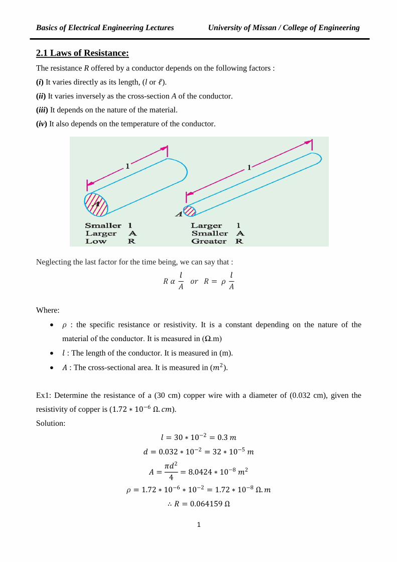
2.1 Laws of Resistance: The resistance R offered by a conductor depends on the following factors :
(i) It varies directly as its length, (l or ℓ).
(ii) It varies inversely as the cross-section A of the conductor.
(iii) It depends on the nature of the material.
(iv) It also depends on the temperature of the conductor.
Neglecting the last factor for the time being, we can say that :
𝑅𝑅 𝛼𝛼 𝑙𝑙𝐴𝐴
𝑜𝑜𝑜𝑜 𝑅𝑅 = 𝜌𝜌 𝑙𝑙𝐴𝐴
Where:
• 𝜌𝜌 : the specific resistance or resistivity. It is a constant depending on the nature of the
material of the conductor. It is measured in (Ω.m)
• 𝑙𝑙 : The length of the conductor. It is measured in (m).
• 𝐴𝐴 : The cross-sectional area. It is measured in (𝑚𝑚2).
Ex1: Determine the resistance of a (30 cm) copper wire with a diameter of (0.032 cm), given the
resistivity of copper is (1.72 ∗ 10−6 Ω. 𝑐𝑐𝑚𝑚).
Solution:
𝑙𝑙 = 30 ∗ 10−2 = 0.3 𝑚𝑚
𝑑𝑑 = 0.032 ∗ 10−2 = 32 ∗ 10−5 𝑚𝑚
𝐴𝐴 =𝜋𝜋𝑑𝑑2
4= 8.0424 ∗ 10−8 𝑚𝑚2
𝜌𝜌 = 1.72 ∗ 10−6 ∗ 10−2 = 1.72 ∗ 10−8 Ω.𝑚𝑚
∴ 𝑅𝑅 = 0.064159 Ω

Basics of Electrical Engineering Lectures University of Missan / College of Engineering
Ex2: A coil consists of (2000 turns) of wire having a cross-sectional area of (0.8 𝑚𝑚𝑚𝑚2). The mean
length per turn is (80 cm) and the resistivity is (0.02 μ Ω.m). Find the resistance of the coil and
power absorbed by the coil when connected across (110 V) DC supply.
Solution: l = 0.8 × 2000 = 1600 m
𝐴𝐴 = 0.8 𝑚𝑚𝑚𝑚2 = 0.8 ∗ 10−6 𝑚𝑚2
∴ 𝑅𝑅 = 0.02 ∗ 10−6 ∗1600
0.8 ∗ 10−6 = 40 Ω
𝑃𝑃 =𝑉𝑉2
𝑅𝑅=
1102
40= 302.5 𝑊𝑊
Ex3: A rectangular carbon block has dimensions 1.0 cm × 1.0 cm × 50 cm.
(i) What is the resistance measured between the two square ends ?
(ii) between two opposing rectangular faces / Resistivity of carbon is 3.5 ∗ 10−5 Ω.m.
Solution:
(i)
𝑅𝑅 = 𝜌𝜌 𝑙𝑙𝐴𝐴
𝐴𝐴 = 1 ∗ 1 = 1 𝑐𝑐𝑚𝑚2 = 10−4 𝑚𝑚2
𝑙𝑙 = 0.5 𝑚𝑚
𝑅𝑅 = 3.5 ∗ 10−5 ∗ 0.5 / 10−4 = 0.175 Ω
(ii)
𝑙𝑙 = 1 𝑐𝑐𝑚𝑚 = 10−2𝑚𝑚
𝐴𝐴 = 1 ∗ 50 = 50 𝑐𝑐𝑚𝑚2 = 5 ∗ 10−3 𝑚𝑚2
𝑅𝑅 = 3.5 ∗ 10−5 ∗ 10−2 / 5 ∗ 10−3 = 7 ∗ 10−5 Ω
2
Basics of Electrical Engineering Lectures University of Missan / College of Engineering
2.2 Temperature Coefficient of Resistance :
The effect of rise in temperature is :
(i) to increase the resistance of pure metals.
(ii) to increase the resistance of alloys, though in their case, the increase is relatively small and
irregular.
(iii) to decrease the resistance of insulators (such as paper, rubber, glass, mica etc.) and partial
conductors such as carbon.
the temperature-coefficient of a material (α) may be defined as : A constant which represents the
increase in resistance per ohm original resistance (per °C) rise in temperature.
Let a metallic conductor having a resistance of (Ro) at (0°C) be heated to (t°C) and let its
resistance at this temperature be (Rt), then the temperature-coefficient at (0° C) is given by (αo) , and
at (t° C) it is given by (αt).
𝑅𝑅𝑡𝑡 = 𝑅𝑅𝑜𝑜(1 + 𝛼𝛼𝑜𝑜𝑡𝑡)
𝛼𝛼𝑡𝑡 =𝛼𝛼𝑜𝑜
1 + 𝛼𝛼𝑜𝑜𝑡𝑡
If the material is working in two different temperatures (t1 & t2), then the resistances can be
computed as :
𝑅𝑅1 = 𝑅𝑅𝑜𝑜(1 + 𝛼𝛼𝑜𝑜𝑡𝑡1)
𝑅𝑅2 = 𝑅𝑅𝑜𝑜(1 + 𝛼𝛼𝑜𝑜𝑡𝑡2)
Ex4: A copper conductor has a resistance temperature coefficient of (1/254.5) per °C at (20°C).
Find the resistance temperature-coefficient at (60°C).
Solution:
𝛼𝛼60 =𝛼𝛼𝑜𝑜
1 + 𝛼𝛼𝑜𝑜 ∗ 60
𝛼𝛼20 =𝛼𝛼𝑜𝑜
1 + 𝛼𝛼𝑜𝑜 ∗ 20⟹
1254.5
=𝛼𝛼𝑜𝑜
1 + 𝛼𝛼𝑜𝑜 ∗ 20
∴ 𝛼𝛼0 =1
234.5 𝑝𝑝𝑝𝑝𝑜𝑜 𝐶𝐶𝑜𝑜
∴ 𝛼𝛼60 =1
294.5 𝑝𝑝𝑝𝑝𝑜𝑜 𝐶𝐶𝑜𝑜
Ex5: A platinum coil has a resistance of (3.146 Ω) at (40°C) and (3.767 Ω) at (100°C). Find the
resistance at (0°C) and the temperature-coefficient of resistance at (40°C).
3
Basics of Electrical Engineering Lectures University of Missan / College of Engineering
Solution:
R100 = R0 (1 + 100 * α0)
R40 = R0 (1 + 40 * α0)
3.7673.146
=R0 (1 + 100 ∗ α0)R0 (1 + 40 ∗ α0)
⇒ α0 = 0.00379 𝑝𝑝𝑝𝑝𝑜𝑜 𝐶𝐶𝑜𝑜
𝑅𝑅100 = 𝑅𝑅𝑜𝑜(1 + 𝛼𝛼𝑜𝑜 ∗ 100)
3.767 = 𝑅𝑅𝑜𝑜(1 + 0.00379 ∗ 100) ⇒ 𝑅𝑅𝑜𝑜 = 2.732 Ω
𝛼𝛼40 =𝛼𝛼𝑜𝑜
1 + 𝛼𝛼𝑜𝑜 ∗ 40=
0.007391 + 0.00739 ∗ 40
=1
304 𝑝𝑝𝑝𝑝𝑜𝑜 𝐶𝐶𝑜𝑜
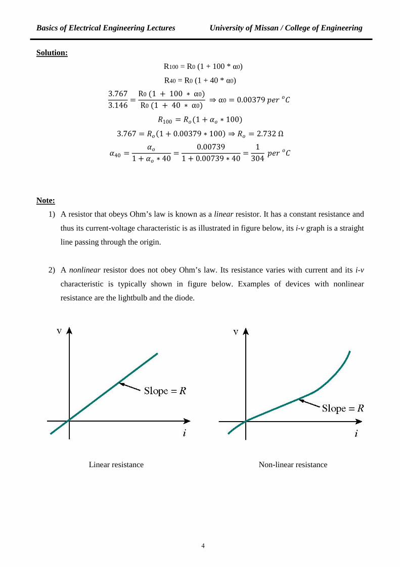
Note:
1) A resistor that obeys Ohm’s law is known as a linear resistor. It has a constant resistance and
thus its current-voltage characteristic is as illustrated in figure below, its i-v graph is a straight
line passing through the origin.
2) A nonlinear resistor does not obey Ohm’s law. Its resistance varies with current and its i-v
characteristic is typically shown in figure below. Examples of devices with nonlinear
resistance are the lightbulb and the diode.
Linear resistance Non-linear resistance
4
Basics of Electrical Engineering Lectures University of Missan / College of Engineering
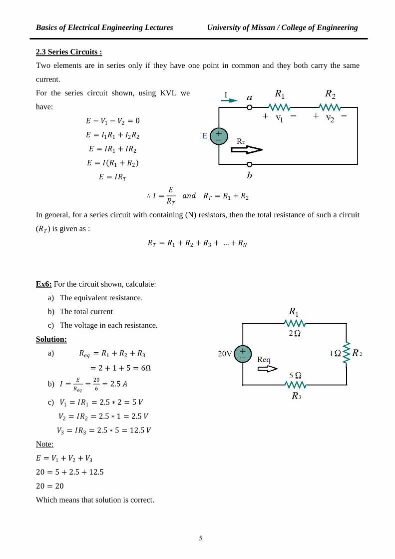
2.3 Series Circuits :
Two elements are in series only if they have one point in common and they both carry the same
current.
For the series circuit shown, using KVL we
have:
𝐸𝐸 − 𝑉𝑉1 − 𝑉𝑉2 = 0
𝐸𝐸 = 𝐼𝐼1𝑅𝑅1 + 𝐼𝐼2𝑅𝑅2
𝐸𝐸 = 𝐼𝐼𝑅𝑅1 + 𝐼𝐼𝑅𝑅2
𝐸𝐸 = 𝐼𝐼(𝑅𝑅1 + 𝑅𝑅2)
𝐸𝐸 = 𝐼𝐼𝑅𝑅𝑇𝑇
∴ 𝐼𝐼 =𝐸𝐸𝑅𝑅𝑇𝑇
𝑎𝑎𝑎𝑎𝑑𝑑 𝑅𝑅𝑇𝑇 = 𝑅𝑅1 + 𝑅𝑅2
In general, for a series circuit with containing (N) resistors, then the total resistance of such a circuit
(𝑅𝑅𝑇𝑇) is given as :
𝑅𝑅𝑇𝑇 = 𝑅𝑅1 + 𝑅𝑅2 + 𝑅𝑅3 + … + 𝑅𝑅𝑁𝑁
Ex6: For the circuit shown, calculate:
a) The equivalent resistance.
b) The total current
c) The voltage in each resistance.
Solution:
a) 𝑅𝑅𝑝𝑝𝑒𝑒 = 𝑅𝑅1 + 𝑅𝑅2 + 𝑅𝑅3
= 2 + 1 + 5 = 6Ω
b) 𝐼𝐼 = 𝐸𝐸𝑅𝑅𝑝𝑝𝑒𝑒
= 206
= 2.5 𝐴𝐴
c) 𝑉𝑉1 = 𝐼𝐼𝑅𝑅1 = 2.5 ∗ 2 = 5 𝑉𝑉
𝑉𝑉2 = 𝐼𝐼𝑅𝑅2 = 2.5 ∗ 1 = 2.5 𝑉𝑉
𝑉𝑉3 = 𝐼𝐼𝑅𝑅3 = 2.5 ∗ 5 = 12.5 𝑉𝑉
Note:
𝐸𝐸 = 𝑉𝑉1 + 𝑉𝑉2 + 𝑉𝑉3
20 = 5 + 2.5 + 12.5
20 = 20
Which means that solution is correct.
5
Basics of Electrical Engineering Lectures University of Missan / College of Engineering
1
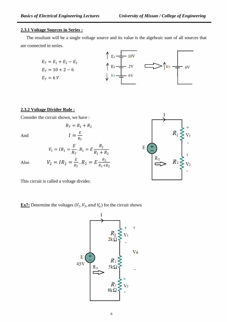
2.3.1 Voltage Sources in Series :
The resultant will be a single voltage source and its value is the algebraic sum of all sources that
are connected in series.
𝐸𝐸𝑇𝑇 = 𝐸𝐸1 + 𝐸𝐸2 − 𝐸𝐸3
𝐸𝐸𝑇𝑇 = 10 + 2 − 6
𝐸𝐸𝑇𝑇 = 6 𝑉𝑉
2.3.2 Voltage Divider Rule :
Consider the circuit shown, we have :
𝑅𝑅𝑇𝑇 = 𝑅𝑅1 + 𝑅𝑅2
And 𝐼𝐼 = 𝐸𝐸𝑅𝑅𝑇𝑇
𝑉𝑉1 = 𝐼𝐼𝑅𝑅1 =𝐸𝐸𝑅𝑅𝑇𝑇
.𝑅𝑅1 = 𝐸𝐸𝑅𝑅1
𝑅𝑅1 + 𝑅𝑅2
Also 𝑉𝑉2 = 𝐼𝐼𝑅𝑅2 = 𝐸𝐸𝑅𝑅𝑇𝑇
.𝑅𝑅2 = 𝐸𝐸 𝑅𝑅2𝑅𝑅1+𝑅𝑅2
This circuit is called a voltage divider.
Ex7: Determine the voltages (𝑉𝑉1,𝑉𝑉3,𝑎𝑎𝑎𝑎𝑑𝑑 𝑉𝑉𝑎𝑎) for the circuit shown
6
Basics of Electrical Engineering Lectures University of Missan / College of Engineering
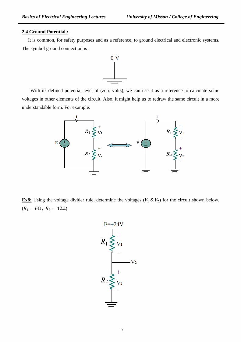
2.4 Ground Potential :
It is common, for safety purposes and as a reference, to ground electrical and electronic systems.
The symbol ground connection is :
With its defined potential level of (zero volts), we can use it as a reference to calculate some
voltages in other elements of the circuit. Also, it might help us to redraw the same circuit in a more
understandable form. For example:
Ex8: Using the voltage divider rule, determine the voltages (𝑉𝑉1 & 𝑉𝑉2) for the circuit shown below.
(𝑅𝑅1 = 6Ω , 𝑅𝑅2 = 12Ω).
7

Basics of Electrical Engineering Lectures University of Missan / College of Engineering
Ex9: For the circuit shown, determine (𝑉𝑉𝑎𝑎𝑎𝑎 ,𝑉𝑉𝑐𝑐𝑎𝑎 ,𝑉𝑉𝑎𝑎 , 𝑎𝑎𝑎𝑎𝑑𝑑 𝑉𝑉𝑐𝑐)
2.5 Parallel Circuits :
Two elements or branches in a circuits are said to be in parallel if they have two points in
common; as a result, they both have the same voltage. For the parallel circuit shown, using (KCL)
we have :
𝐼𝐼 = 𝐼𝐼1 + 𝐼𝐼2 + 𝐼𝐼3
=𝑉𝑉1
𝑅𝑅1+𝑉𝑉2
𝑅𝑅2+𝑉𝑉3
𝑅𝑅3
𝑠𝑠𝑠𝑠𝑎𝑎𝑐𝑐𝑝𝑝 𝑉𝑉1 = 𝑉𝑉2 = 𝑉𝑉3 = 𝐸𝐸 = 𝑉𝑉
𝑎𝑎𝑎𝑎𝑑𝑑 𝐼𝐼 =𝑉𝑉𝑅𝑅𝑇𝑇
∴𝑉𝑉𝑅𝑅𝑇𝑇
=𝑉𝑉𝑅𝑅1
+𝑉𝑉𝑅𝑅2
+𝑉𝑉𝑅𝑅3
⟹1𝑅𝑅𝑇𝑇
=1𝑅𝑅1
+1𝑅𝑅2
+1𝑅𝑅3
In general, for (N) resistors connected in parallel, then : 1𝑅𝑅𝑇𝑇
=1𝑅𝑅1
+1𝑅𝑅2
+1𝑅𝑅3
+ … +1𝑅𝑅𝑁𝑁
And if we use conductance (G), then the equation above becomes :
𝐺𝐺𝑇𝑇 = 𝐺𝐺1 + 𝐺𝐺2 + 𝐺𝐺3 + … + 𝐺𝐺𝑁𝑁
8
Basics of Electrical Engineering Lectures University of Missan / College of Engineering
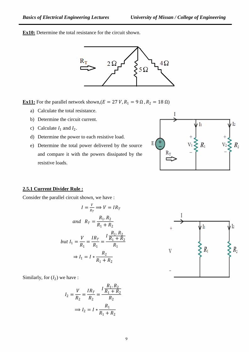
Ex10: Determine the total resistance for the circuit shown.
Ex11: For the parallel network shown,(𝐸𝐸 = 27 𝑉𝑉,𝑅𝑅1 = 9 Ω ,𝑅𝑅2 = 18 Ω)
a) Calculate the total resistance.
b) Determine the circuit current.
c) Calculate 𝐼𝐼1 and 𝐼𝐼2.
d) Determine the power to each resistive load.
e) Determine the total power delivered by the source
and compare it with the powers dissipated by the
resistive loads.
2.5.1 Current Divider Rule :
Consider the parallel circuit shown, we have :
𝐼𝐼 = 𝑉𝑉𝑅𝑅𝑇𝑇⟹ 𝑉𝑉 = 𝐼𝐼𝑅𝑅𝑇𝑇
𝑎𝑎𝑎𝑎𝑑𝑑 𝑅𝑅𝑇𝑇 =𝑅𝑅1.𝑅𝑅2
𝑅𝑅1 + 𝑅𝑅2
𝑎𝑎𝑏𝑏𝑡𝑡 𝐼𝐼1 =𝑉𝑉𝑅𝑅1
=𝐼𝐼𝑅𝑅𝑇𝑇𝑅𝑅1
=𝐼𝐼 𝑅𝑅1.𝑅𝑅2𝑅𝑅1 + 𝑅𝑅2𝑅𝑅1
⇒ 𝐼𝐼1 = 𝐼𝐼 ∗𝑅𝑅2
𝑅𝑅1 + 𝑅𝑅2
Similarly, for (𝐼𝐼2) we have :
𝐼𝐼2 =𝑉𝑉𝑅𝑅2
=𝐼𝐼𝑅𝑅𝑇𝑇𝑅𝑅2
=𝐼𝐼 𝑅𝑅1.𝑅𝑅2𝑅𝑅1 + 𝑅𝑅2𝑅𝑅2
⟹ 𝐼𝐼2 = 𝐼𝐼 ∗𝑅𝑅1
𝑅𝑅1 + 𝑅𝑅2
9
Basics of Electrical Engineering Lectures University of Missan / College of Engineering
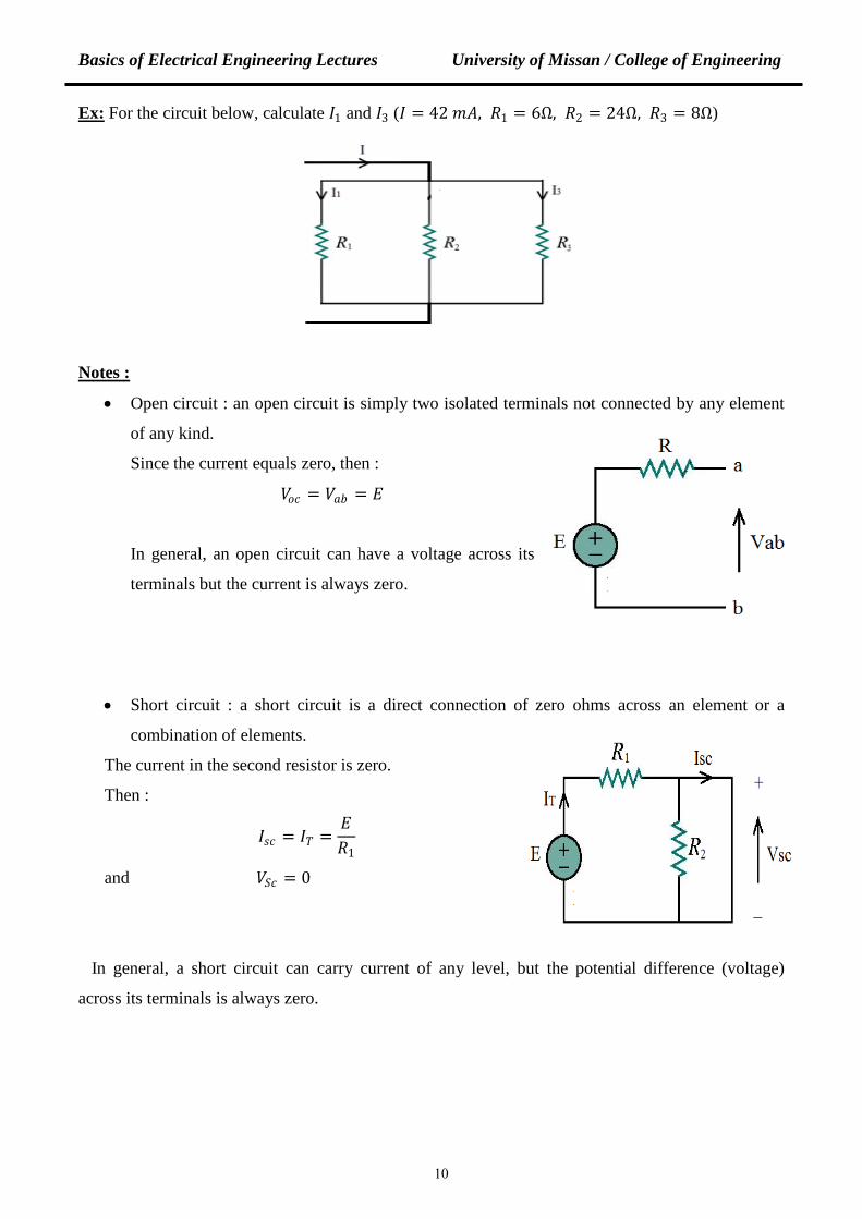
Ex: For the circuit below, calculate 𝐼𝐼1 and 𝐼𝐼3 (𝐼𝐼 = 42 𝑚𝑚𝐴𝐴, 𝑅𝑅1 = 6Ω, 𝑅𝑅2 = 24Ω, 𝑅𝑅3 = 8Ω)
Notes :
• Open circuit : an open circuit is simply two isolated terminals not connected by any element
of any kind.
Since the current equals zero, then :
𝑉𝑉𝑜𝑜𝑐𝑐 = 𝑉𝑉𝑎𝑎𝑎𝑎 = 𝐸𝐸
In general, an open circuit can have a voltage across its
terminals but the current is always zero.
• Short circuit : a short circuit is a direct connection of zero ohms across an element or a
combination of elements.
The current in the second resistor is zero.
Then :
𝐼𝐼𝑠𝑠𝑐𝑐 = 𝐼𝐼𝑇𝑇 =𝐸𝐸𝑅𝑅1
and 𝑉𝑉𝑆𝑆𝑐𝑐 = 0
In general, a short circuit can carry current of any level, but the potential difference (voltage)
across its terminals is always zero.
10