
Course - Белорусский национальный технический ... · Web viewFor...
106
Algorithm of thermo-gas dynamic end heat transfer modeling for turbine blades 1
Transcript of Course - Белорусский национальный технический ... · Web viewFor...

Algorithm of thermo-gas dynamic end heat transfer modeling for turbine blades
National Aviation Academy of Azerbaijan Republic
Baku, 2013
1

This document has been prepared by the financial support of European Union. Authors from National Aviation Academy of Azerbaijan Republic, National Aviation Academy of Azerbaijan Republic are responsible for the content of this document. This publication reflects the views only of the authors, and it can not be regarded as the European Union's official position.
The book is developed in frame of project “Development of Training Network for Improving Education in Energy Efficiency” acronym: ENERGY, grant Nr. 530379-TEMPUS-1-2012-1-LVTEMPUS-JPCR.
Project was approved by the European Commission in frame of the Program Tempus IV – Fifth call for proposals (Programme guide EACEA/25/2011).
Sub-programme: Joint Projects
Action: Curricular Reform
Deliverable: 2.1 Development and translation of study courses within the frame of direction “Thermo-gas dynamic end heat transfer modeling for turbine blades”.
Project coordinator: Leonids Ribickis
Editors:
Institution: Riga Technical University
2

Contributors
Adalat Samadov Soltan, vice-rector of Educational affairs of the National Academy of
Aviation (Azerbaijan, Baku), Doctor of Technical Science, Associated professor of
“Aircrafts and Aviation Engines” Department. Author of many publications in the field of
gas dynamics and heat transfer in gas turbines as well as cooling systems for high
temperature gas turbine elements.
AZ1045, Baku city ., Bina settlement., 25th km highway., National Aviation Academy.
Parviz Abdullayev Shahmurad, Assoc Prof DPh Eng.Research interests: aircraft gas turbine engines condition monitoring methods on the basis of modern mathematical methods and techniques (neural networks, fuzzy logic).Present position: head of Aircrafts and Aviation Engines Department of the Azerbaijan National Academy of Aviation.AZ1045, Baku city ., Bina settlement., 25th km highway., National Aviation Academy.
Rzagulu Agaverdiyev Sultan, National Aviation Academy (NAA) « Aircraft and
aviation engines » department lecturer and ph.d. candidate, Azerbaijan Airlines (SilkWay
Technics) airframe and power plant engineer.
AZ1045, Baku city ., Bina settlement., 25th km highway., National Aviation Academy.
phone./fax: (+994 12) 497 28 29; 497 28 24; 497 28 38; 456 05 03
mail adress : [email protected];
3

Introduction
« Algorithm of thermo-gas dynamic end heat transfer modeling for turbine blades »
NAA ‘Aircraft and aviation engines’ department lecturer, Azerbaijan Airlines (SilkWay
Technics) airframe and power plant engineer: Agaverdiyev R.S ph.d. candidate
supervisor: Samadov A.S ph.d.
Abdullayev P.S ph.d.
This book is overview of existing Theoretical background of thermo-gas dynamic
end heat transfer modeling principles for turbine blades. The purpose of this book is the
justification of scientific and modeling principles of the thermo-gas dynamic end heat
transfer processes. In this course we investigate the thermo-gazo dynamic end heat
transfer processes and modeling principles in turbine blade cooling technology via
Unigraphics, Ansys and Fluent software at aviation engines. Primarily we analyze internal
convective flows and film cooling methods.
Executive summary
Algorithm of thermo-gas dynamic end heat transfer modeling for turbine blades.
Title 1: Eulerian models
In Eulerian models the gas and the solid phases are treated as interpenetrating phases, and the theory behind such models is basically an extension of the classical kinetic theory that takes non- ideal particle-article collisions and gas-particle drag into account.
Title 2: Cooling via internal convective flows
The purpose of cooling technology gas turbine components via internal convective flows is obtain the highest overall cooling effectiveness with the lowest possible penalty on the thermodynamic cycle performance.
4

Title 3: Fundamentals of Film Cooling Performance
The purpose of film cooling is reduce the heat transfer to the wall is by reducing the gas temperature near the wall, i.e. reducing the driving temperature potential for heat transfer to the wall.
Title 3.1. Correlations of Film Cooling Performance
The primary measure of film cooling performance is the film effectiveness, η, since this has a dominating effect on the net heat flux reduction
Title 4: A Conjugate Heat Transfer Method for Turbine Blade Cooling
Conjugate heat transfer (CHT) is the process regarding the interaction between the heat conduction inside the solid body and the heat transfer in the surrounding fluid. In real problems, the near wall flow is highly influenced by the solid thermal status.
5

Title 1. Eulerian models
In Eulerian models the gas and the solid phases are treated as interpenetrating
phases, and the theory behind such models is basically an extension of the classical kinetic
theory that takes non- ideal particle-article collisions and gas-particle drag into account. In
this scheme, collections of particles are modelled using continuous medium mechanics.
The solid particles are generally considered to be identical having a representative
diameter and density, meaning that the particle phase is volume averaged. The general
idea in formulating such a multi-fluid model is to treat each phase as an interpenetrating
continuum and therefore to construct integral balances of continuity, momentum and
energy for both phases with appropriate boundary conditions and jump conditions for the
phase interfaces. Since such a resulting continuum approximation for the solid phase has
no equation of state and obviously lacks variables such as viscosity and normal stress,
certain averaging techniques and assumptions are required to obtain a momentum balance
for the solid phase.
Figure 1 shows a snapshot of liquid fuel spray coming out of an injector nozzle in a
realistic gas-turbine combustor. Here the spray atomization was simulated using a
stochastic secondary breakup model (Apte et al. 2003a) with point-particle approximation
for the droplets. Very close to the injector, it is observed that the spray density is large and
the droplets cannot be treated as point-particles. The volume displaced by the liquid in this
region is significant and can alter the gas-phase flow and spray evolution.
In order to address this issue, one can compute the dense spray regime by an
Eulerian Eulerian technique using advanced interface tracking/level-set methods
(Sussman et al. 1994; Tryggvason et al. 2001; Herrmann 2003). This, however, is
computationally intensive and may not be viable in realistic complex configurations. We
therefore plan to develop a methodology based on Eulerian-Lagrangian technique which
6

will allow us to capture the essential features of primary atomization using models to
capture interactions between the fluid and droplets and which can be directly applied to
the standard atomization models used in practice. The numerical scheme for unstructured
grids developed by Mahesh et al. (2003) for incompressible flows is modified to take into
account the droplet volume fraction. The numerical framework is directly applicable to
realistic combustor geometries. Our main objectives in this work are:
Develop a numerical formulation based on Eulerian-Lagrangian techniques with
models for interaction terms between the fluid and particles to capture the Kelvin-
Helmholtz type instabilities observed during primary atomization.
Validate this technique for various two-phase and particulate flows.
Assess its applicability to capture primary atomization of liquid jets in conjuction
with secondary atomization models.
Figure 1. Snapshot spray from a gas-turbine fuel-injector.
7

Although constitutive relations according to the kinetic theory of particle flow have
been incorporated into recent models, pure CFD models for fluid bed granulation still
suffer from the fact that the contact between fluid, particles and boundary surfaces is not
considered explicitly with respect to particle inertia and the mechanical properties of the
particles. This limits the ability of CFD multiphase models to adequately represent
particle-particle and fluid-particle interactions thereby reducing the accuracy of the
prediction of both the fluid and the particle dynamics. Considering the required
computational power and complexity, gas-particle flow fields calculated with the multi-
fluid interpenetrating approach of the Eulerian granular multi-phase model is still a fast
method to calculate flow fields, as it is well known from simple particle systems as spray-
drying and conveying systems etc. Due to the obvious need for accounting precise particle
level properties into fluid bed hydrodynamic models, pure Eulerian CFD models must be
regarded as inappropriate even in an industrial context.
Title 2. Cooling via internal convective flows
The purpose of cooling technology of Aviation Engines Gas Turbine components
via internal convective flows is obtain the highest overall cooling effectiveness with the
lowest possible penalty on the thermodynamic cycle performance.
The coolant is extracted from the internal channel for impingement and pin fin
cooling. Jet impingement is a very aggressive cooling technique which very effectively
removes heat from the vane wall. However, this technique is not readily applied to the
narrow trailing edge. The blade trailing edge is cooled using pin-fins (an array of short
cylinders).
8
Figure1. Aviation Engine Cross Section
The pin-fins increase the heat transfer area while effectively mixing the coolant air
to lower the wall temperature of the vanes. After impinging on the walls of the airfoil, the
coolant exits the vane and provides a protective film on the blade external surface.
Similarly, the coolant traveling through the pin-fin array is ejected from the trailing edge
of the airfoil.
The importance of improving the cooling of gas turbine blades have seen an
increasing demand of, initially experimental evidences, and now well validated numerical
methods for use as optimization tools. The effect of variating rib-sizes, Reynolds number
etc. have been documented in both numerical simulations and experimentally.
9

Figure 2. Turbine blade cooling
Although the many merits of experimental evidence, there is a problem that should
be recognize when performing experiments: it is very difficult to achieve conditions which
enable measured data to be dependent on only a single parameter. In many investigations
the data is obscured by slight perturbations in Reynolds number, different heating, rotation
number etc. These unknowns add up to a level of uncertainty in the measured data, which
should be considered when making comparisons to the predicted result. In numerical
simulations on the other hand it is very easy to ensure an exact Reynolds number or that
the flow is incompressible, or that the temperature behave as a passive scalar etc., all
conditions which can only be an approximation of the real world. It is thus important that
both measurements and predictions are made under as identical conditions as possible, to
10

enable an accurate evaluation of turbulence and heat transfer models. The appearance of
Direct Numerical Simulations have had a great impact on turbulence modelling as these
numerical 'experiments' could be completely controlled, with known boundary conditions.
These simulations also provide a wealth of information. DNS are however very
computational costly, and only some fundamental _ows can be studied with this approach.
In other cases, such as the internal cooling systems of a gas turbine blade, one needs to
rely on data from experiments.
Impingement Cooling
Impingement cooling is commonly used near the leading edge of the airfoils,
where the heat loads are the greatest. With the cooling jets striking (impinging) the blade
wall, the leading edge is well suited for impingement cooling because of the relatively
thick blade wall in this area.
Impingement can also be used near the mid-chord of the vane. Figure 3
shows jet impingement located throughout the cross-section of an inlet guide vane.
Several aspects must be considered when developing efficient cooling designs. The effect
of jet-hole size and distribution, cooling channel cross-section, and target surface shape all
have significant effects on the heat transfer coefficient distribution. Jet impingement near
the mid-chord of the blade is very similar to impingement on a flat plate; however, the
sharp curvature at the leading edge of the vane must be considered when utilizing
impingement in this region. As shown in figure 3, many jets are used to increase the heat
transfer from the vane wall. It has been shown by Metzger et al [Experimental and
Numerical Impingement Heat Transfer in an Airfoil Leading-Edge Cooling Channel With
Cross-Flow Revised 26.09.2007; Published 26.11.2008] that multiple jets perform very
differently from a single jet striking a target surface. They concluded that for multiple jets,
the Nusselt number is strongly dependent on the Reynolds number, while there is no
significant dependence on the jet-to-target plate spacing.11

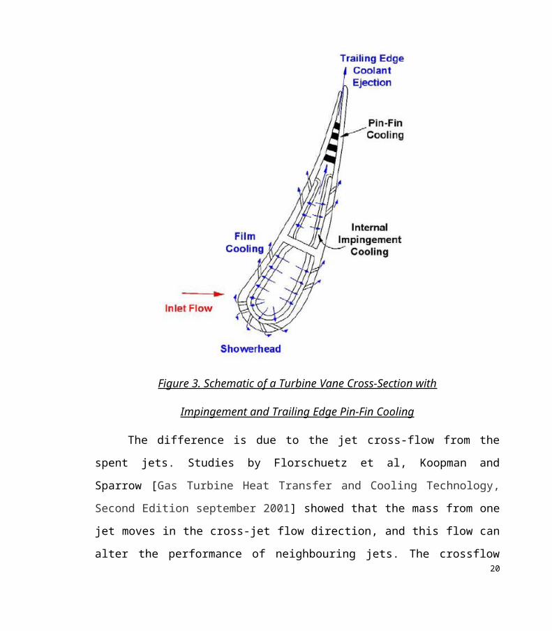
Figure 3. Schematic of a Turbine Vane Cross-Section with
Impingement and Trailing Edge Pin-Fin Cooling
The difference is due to the jet cross-flow from the spent jets. Studies by
Florschuetz et al, Koopman and Sparrow [Gas Turbine Heat Transfer and Cooling
Technology, Second Edition september 2001] showed that the mass from one jet moves in
the cross-jet flow direction, and this flow can alter the performance of neighbouring jets.
The crossflow attempts to deflect a jet away from its impinging location on the target
plate. In situations with very strong cross-flow and sufficiently large jet-to-target plate
spacing, the cross-flow can completely deflect the jet away from the impingement surface.
12

Florschuetz and Su [Gas Turbine Heat Transfer and Cooling Technology, Second Edition
september 2001] reported that cross-flow decreases the overall heat transfer from the
impingement surface. They determined that cross-flow enhances the convective heat
transfer, but the enhancement from the jets decreases, as the jets are deflected. Because the
enhancement from the impingement jets is much greater than the convective enhancement,
the overall Nusselt numbers decrease in the presence of cross-flow.
As shown in figure 4 in ansys program software via internal convective flows throw
radial cooling holes obtained the temperature contour. For obtaining temperature
distribution in turbine blade 3D model in ansys 14 software it is necessary to prepare the
algorithm of steps as shown below:
1. Step1 – the 3D turbine blade model sketch (2D) preparing in ansys 14 workbench
“geometry” section;
2. Step2 – the 3D turbine blade model preparing in ansys 14 workbench “geometry”
section ;
3. Step3 – the 3D turbine blade model mesh generating in ansys 14 workbench
“mesh” section (the same process shown in fig5 in plate);
4. Step4 – In this step blade with generated mesh transferred to in ansys 14
workbench “fluent” section and in this section obtained blade temperature
distribution
5. Step5 – For obtaining the results of temperature distribution in blade the solution
transferred to ansys 14 workbench “result” section (the temperature contour
obtained in mentioned section shown in fig4)
13

Figure 4. Temperature contour
In figure 5 you can see the plate with rectangular mesh. A typical test model is
shown in figure 6. As shown in this figure, the coolant jets impinge on the target surface
from the jet plate in an inline array[Robert Kwiatkowski, Roman Doma´nski <<
Numerical analyses of heat transfer in high-temperature loaded turbine Blades>> Institute
of Heat Engineering University of Technology, Warsaw Journal of Power
Technologies;Dec2012, Vol. 92 Issue 4, page#208]. As the coolant travels along the test
surface, the spent air from the upstream jets effects the heat transfer coefficient
distributions of the downstream jets, and this effect increases as more spent air
accumulates on the target surface. Obtained temperature contour shown in figure 6.
14

Correlations based on experimental data were developed by Kercher and Tabakoff
and Florschuetz et al [D. Kercher, and W. Tabakoff, “Heat Transfer by a Square Array of
Round Air Jets Impinging Perpendicular to a Flat Surface Including the Effect of Spent
Air,” Journal of Engineering for Power, 92 (1970): pages 73-82]. to estimate the heat
transfer enhancement from an array of impinging jets. Although the correlations are in
different forms, they both demonstrate the dependence of the heat transfer enhancement
on the amount of cross-flow. Florschuetz et al. also showed the cross-flow effect is much
stronger in staggered arrays of jets than an inline array. Bailey and Bunker extended the
correlation developed by Florschuetz et al. to include the effect of jet spacing. The
correlation has been extended to include dense impingement arrays.
Figure 5. Plate (with rectangular mesh)
15

Huang et al. controlled the direction of the cross-flow and obtained detailed distributions
of the heat transfer coefficients for three target plates. Their results clearly indicate when
the cross-flow travels in two opposite directions, the heat transfer enhancement on the
target plate is much greater than when the cross-flow is restricted to one direction. This
study was extended by Ekkad et al. to include the effect of coolant extraction for film
cooling. The heat transfer enhancement on the target plate decreases near the edges due to
the decreased coolant flow (for film cooling). Wang et al. investigated cross-flow through
a confined space; they also considered cross-flow traveling in one direction and two
directions. This study also concluded that increasing cross-flow results in degraded heat
transfer; however, the heat transfer coefficient distribution is much more uniform.
The heat transfer coefficient distributions on target plates with stretched arrays of
impinging jets were studied by Gao et al.
This array varies from the traditional square array in which the jets are evenly
spaced. They concluded the existing correlations for square arrays over-predict the effect
of cross-flow in the target surface. The presence of initial cross-flow also effects the heat
transfer enhancement from the target plate. The cross-flow described
above is created by the spent flow from the jets. Therefore, the first row of jets is not
affected by the cross-flow. However, in many situations, cross-flow may develop
upstream of the first row. The flow from upstream of the impingement jets can
significantly alter the flow near the jets, and thus alter the heat transfer coefficients on the
target surface. Florschuetz et al. investigated the effect of initial cross-flow on the heat
transfer enhancement. The results of this study were similar to those mentioned above
describing cross-flow:
the heat transfer enhancement on the target plate decreases when initial cross-flow is
present.
16

Figure 6. The coolant jets impinge on the target surface from the jet plate
One of the main directions for the performance efficiency improvement of the
power system in the modern aviation engines include increasing of the work flow
conditions, and most of all it’s come to the temperature increasing in the gas turbine inlet.
In this case the most complicated problem is the design reliability assurance of the nozzle
and rotating blades of the gas turbine, which falls under the direct effect of the high
potential gas flow and significant loads. Therefore improvement and defining the ways for
thermal protection, the lifetime and reliability increasing of the turbine details have a great
scientific and practical importance.
The activities for the temperature increasing can be compared to several directions.
However assimilation of high in AGTE mainly reached by refinement of the cooling
systems for turbine blades. It is especially necessary to note, that with increase the
requirement to accuracy of results will increase. In other words, at allowed values of
AGTE metal temperature , the absolute error of temperature
17
calculation should be in limits ( ), that is no more than 2-3%. This is difficult to
achieve (multiconnected fields with various cooling channels, variables in time and
coordinates boundary conditions). Such problem solving requires application of modern
and perfect mathematical device.
In classical statement a heat conduction differential equation in common case for
non-stationary process with heat distribution in multi–dimensional area (Fourier-
Kirchhoff equation) has a kind [Leontiev, A.I., Osipov, M.I., Ivanov, V.L., Manushin,
E.A., (2004), «Heat exchange apparatus and cooling systems of gas turbine and combined
arrangements », Moscow, MGTU nam. N.E. Bauman, page 592; Zisina-Molojen, L.N. and
etc. (1974), «Heat exchange in turbomachines», Leningrad, Mashinostroeniye, 1974, page
336]:
(1)
where , and - accordingly material density, thermal capacity, and heat conduction;
- internal source or drain of heat, and - is required temperature.
Research has established that the temperature condition of the airfoil with radial cooling
channels can be determined as two-dimensional [Leontiev, A.I., Osipov, M.I., Ivanov,
V.L., Manushin, E.A., (2004), «Heat exchange apparatus and cooling systems of gas
turbine and combined arrangements », Moscow, MGTU nam. N.E. Bauman, page 592;
Zisina-Molojen, L.N. and etc. (1974), «Heat exchange in turbomachines», Leningrad,
Mashinostroeniye, 1974, page 336]. Besides, if to suppose constancy of physical
properties and absence of internal sources (drains) of heat, then the temperature field
under fixed conditions will depend only on the skew shape and on the temperature
distribution on the skew boundaries. In this case, equation (1) will look like:
(2)
18

When determining particular temperature fields in gas turbine elements are used boundary
conditions of the third kind, describing heat exchange between the skew field and the
environment (on the basis of a hypothesis of a Newton-Riemann). In that case, these
boundary conditions will be recorded as follows:
(3)
This following equation characterizes the quantity of heat transmitted by convection from
gas to unit of a surface of a blade and assigned by heat conduction in a skew field of a
blade.
(4)
Equation (4) characterizes the heat quantity assigned by convection of the cooler,
which is transmitted by heat conduction of the blade material to the surface of cooling
channels: where - temperature of environment at ; - field temperature at
(temperature of the cooler), where - quantity of outlines; - temperature on an outline
at (outside outline of blade); - temperature on an at (outline of
cooling channels); - heat transfer factor from gas to a surface of a blade (at ); -
heat transfer factor from a blade to the cooling air at ; - thermal conductivity of
the material of a blade; - external normal on an outline of researched area.
For the solution of this boundary problem (2)-(4) four numerical methods are used:
Methods of Finite Differences (MFD), Finite Element Method (FEM), probabilistic
method (Monte-Carlo method), and Boundary Integral Equations Method (BIEM) (or its
discrete analog ─ Boundary Element Method (BEM)).
Let us consider BIEM application for the solution of problem (2)-(4) [Leontiev, A.I.,
Osipov, M.I., Ivanov, V.L., Manushin, E.A., (2004), «Heat exchange apparatus and 19
cooling systems of gas turbine and combined arrangements », Moscow, MGTU nam.
N.E. Bauman, page 592; Zisina-Molojen, L.N. and etc. (1974), «Heat exchange in
turbomachines», Leningrad, Mashinostroeniye, 1974, page 336; Pashayev, A.M., Askerov,
D.D., Sadiqov, R.A., Samedov, A.S. (2005), «Numerical modeling of gas turbine cooled
blades», International Journal of Aviation of Vilnius Gediminas , Technical University.,
vol. 9, № 3, 2005, page 9-18].
The function , continuous with the derivatives up to the second order, satisfying
the Laplace equation in considered area, including and its outline , is harmonic.
Consequence of the Grin integral formula for the researched harmonic function
is the ratio:
(5)
where - variable at an integration of the distance between point and “running”
on the outline - point; - temperature on the outline . The temperature value in some
point lying on the boundary is determined (as limiting at approach of point to
the boundary)
(6)
With allowance of the boundary conditions (2)-(3), after collecting terms of terms and
input of new factors, the ratio (6) can be presented as a linear algebraic equation,
computed for the point :
(7)
20

where, n is the quantity of sites of a partition of an outside outline of a blade
on small sections , is the quantity of sites of a
partition of outside outlines of all cooling channels on small sections .
Let us note, that unknowns in the equation (7) except the unknown of true value in the
point are also mean on sections of the outlines partition and temperatures
and (total number ).
From a ratio (7), we shall receive the required temperature for any point, using the formula
(5):
(8)
where
In activities [Zisina-Molojen, L.N. and etc. (1974), «Heat exchange in turbomachines»,
Leningrad, Mashinostroeniye, 1974, page 336] the discretization of a line by a
many discrete point and integrals that are included in the equations as logarithmic
potentials, was calculated approximately with the following ratios:
21

, (9)
, (10)
(where
In contrast to [2], we offer to decide the given boundary value problem (2)-(4) as follows.
We locate the distribution of temperature as follows:
, (11)
where -smooth closed Jordan curve; -quantity of cooled channels; -
density of a logarithmic potential uniformly distributed on .
Thus curve are positively oriented and are given in a parametric kind: ;
; ; .
Using BIEM and expression (11) we shall put problem (2)-(4) to the following system of
boundary integral equations:
,
(12)
where
(12.1).
22

For the singular integral operator’s evaluation, which are included in (12) the discrete
operators of the logarithmic potential with simple and double layer are investigated. Their
connection and the evaluations in modules term of the continuity (evaluation such as
assessments by A. Zigmound are obtained) is shown
Theorem (main)
Let
(12.2)
And let the equation (12) have the solution (the set of continuous functions on Г).
Then such that the discrete system > , obtained from (12) by
using the discrete double layer potential operator (its properties has been studied), has
unique solution
(12.3)
where is constant, depending only on --the sequence of partitions of ;
- the sequence of positive numbers such that the pair ( ), satisfies the
condition .
Let , where is diameter , and the splitting is that, which is satisfied the
condition
(12.4)
Then for all ( - space of all functions continuous on ) and , ( )
23

(12.5)
,
(12.6)
where
- two-parameter quadrature formula (depending on and parameters) for
logarithmic double layer potential - double layer logarithmic potential operator
– constant, dependent only from a curve is a module of a continuity of
functions ;
(12.7)
- two-parameter quadrature formula (depending on and parameters) for
logarithmic potential simple layer; - simple layer logarithmic potential operator
(12.8)
Thus are developed effective from the point of view of realization on computers the
numerical methods basing on constructed two-parametric quadratute processes for the
discrete operators logarithmic potential of the double and simple layer. Their systematic
errors are estimated, the methods quadratures mathematically are proved for the
approximate solution Fredholm I and II boundary integral equations using Tikhonov 24

regularization and are proved by appropriate theorems [Pashayev, A.M., Askerov, D.D.,
Sadiqov, R.A., Samedov, A.S. (2005), «Numerical modeling of gas turbine cooled
blades», International Journal of Aviation of Vilnius Gediminas , Technical University.,
vol. 9, № 3, 2005, page 9-18; A.M.Pashaev, R.A.Sadiqov, C.M.Hajiev, (2002), «The
BEM Application in development of Effective Cooling Schemes of Gas Turbine Blades».
6th Bienial Conference on Engineering Systems Design and Analysis, Istanbul, Turkey,
July, 8-11, 2002].
The given calculating technique of the blade temperature field can be applied also to
blades with the plug–in deflector. On consideration blades with deflectors in addition to
boundary condition of the III kind adjoin also interfaces conditions between segments of
the outline partition as equalities of temperatures and heat flows
, (13)
, (14)
where - number of segments of the outline partition of the blade cross-section; x, y -
coordinates of segments. At finding of cooler T best values, is necessary to solve the
inverse problem of heat conduction. For it is necessary at first to find solution of the heat
conduction direct problem with boundary condition of the III kind from a gas leg and
boundary conditions I kinds from a cooling air leg
(15)
where -the unknown optimum temperature of a wall of a blade from a leg of a cooling
air.
The developed technique for the numerical solution of stationary task of the heat
conduction in cooled blades can be distributed also to quasistationary case.
25

Let us consider a third boundary-value problem for the heat conduction quasilines
equation:
(16)
(17)
For linearization of tasks (16) - (17) we shall use the Kirchhoff permutation:
(18)
Then equation (16) is transformed into the following Laplace equation:
(19)
For preserving convection additives in boundary-value condition (17), we shall accept in
initial approximation . Then from (18) we have
. (20)
And the regional condition (17) will be transformed as follows:
(21)
So, the stationary problem (19) with (21) is solved by boundary integrated equations
method.
The most important role in the blade raw analysis and improvement belongs to the
aerodynamic estimation methods, which proceed to the gas-dynamic efficiency estimation
and for the heat exchange problem research.
26

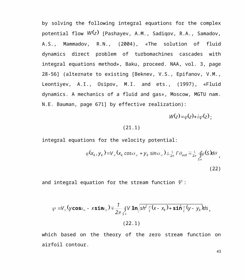
On the basis of potential flow theory, the velocity distribution of gas flow around the
airfoil has been defined by solving the following integral equations for the complex
potential flow [Pashayev, A.M., Sadiqov, R.A., Samadov, A.S., Mammadov, R.N.,
(2004), «The solution of fluid dynamics direct problem of turbomachines cascades with
integral equations method», Baku, proceed. NAA, vol. 3, page 28-56] (alternate to
existing [Beknev, V.S., Epifanov, V.M., Leontiyev, A.I., Osipov, M.I. and ets., (1997),
«Fluid dynamics. A mechanics of a fluid and gas», Moscow, MGTU nam. N.E. Bauman,
page 671] by effective realization):
; (21.1)
integral equations for the velocity potential:
, (22)
and integral equation for the stream function :
,
(22.1)
which based on the theory of the zero stream function on airfoil contour.
In this: - the value of velocity potential; - the main flow velocity; - the
angle between the velocity vector and the blade raw axis; - the velocity circulation;
- the angle that corresponds to the outlet edge of the airfoil.
The integral equation (22) solved by the following received approximating equation:
, (22.2)
where, , , is the number of divided parts of the airfoil.
27
The velocity potential distribution along the airfoil has been received by solving the
system of the linear algebraic equations. The flow velocity magnitude determined using
velocity potential differentiation along the airfoil contour , i.e. .
As opposite to potential flow, the heat-conducted viscous turbulent flow in the turbine
blade channel is explored based on Navier-Stokes equations. As a turbulence models the
standard [Launder, B.E., Spalding, D.B., (1974), «The Numerical Computation of
Turbulent Flows», Journal of Computational Methods in Applied Mechanics and
Engineering, vol. 3, page 269-289] and Spalart-Allmaras models used [Spalart, P. and
Allmaras, S., (1992), «A one-equation turbulence model for aerodynamic flows»,
Technical Report AIAA-92-0439, American Institute of Aeronautics and Astronautics,
1992]. The Navier-Stokes equations solved by ANSYS CFX10© [Imgrund, M.C. (1992),
ANSYS® Verification Manual, Swanson Analysis Systems, Inc] (based on finite element
method) and Fluent© [Fluent. Fluent Inc., (2001), Centerra Resource Park, Cavendish
Court, Lebanon, NH 03766, USA] (based on control volume method) software’s. As the
meshing tool Gambit© software, and for 3D modeling – Solid Works10© have been used.
The velocity distribution data along the airfoil are incoming for determining outer
boundary heat exchange conditions. In case of potential flow, the heat transfer coefficient
of gas flow defined by using integral equation for the energy of heat boundary layer
[Zisina-Molojen, L.N. and etc. (1974), «Heat exchange in turbomachines», Leningrad,
Mashinostroeniye, 1974, page 336; Galitseiskiy, G. and etc., (1996), «A thermal guard of
blades», Moscow, Moscow Aviation Institute, page 356; Kopelev, S.Z., Slitenko, A.F.,
(1994), «Construction and calculation of GTE cooling systems», Ukraina, Kharkov,
Osnova, page 240]. Correction to the base values of heat coefficient was made by using
the recommendations, that was approved by experiment-calculated way [Zisina-Molojen,
L.N. and etc. (1974), «Heat exchange in turbomachines», Leningrad, Mashinostroeniye,
1974, page 336; Galitseiskiy, G. and etc., (1996), «A thermal guard of blades», Moscow,
Moscow Aviation Institute, page 356; Kopelev, S.Z., Slitenko, A.F., (1994), 28

«Construction and calculation of GTE cooling systems», Ukraina, Kharkov, Osnova, page
240]. For the internal heat exchange boundary conditions determination the correlation
between inner geometry and hydrodynamic with heat models are used.
At known geometry of the cooling scheme, for the convective heat exchange local
coefficients definition of the cooler by the standard empirical formulas it is necessary
to have the basic data’s of the air flow distribution in cooling channels.
For example, for blades with deflector and with cross current, the value of the airflow
for blade cooling can be defined with the following:
, (22.3)
where , -the gas and air temperature coefficients; - coefficient of the form; - the
characteristic size in the formula ; , - cooler dynamic viscosity and heat
conductivity coefficients; - the Bio criterion for the blade wall; - the total area of
passage for air; and - coefficient and exponent ratio in criteria formulas for convective
heat exchange for considered cooling parts.
To determine the distribution of flow in the blade cooling system, an equivalent hydraulic
scheme is built.
The construction of the equivalent hydraulic tract circuit of the vane cooling is connected
with the description of the cooled vane design. The whole passage of coolant flow is
divided in some definite interconnected sections, the so-called typical elements, and every
one has the possibility of identical definition of hydraulic resistance. The points of
connection of typical elements are changed by node points, in which the streams, mergion
or division of cooler flows is taking places proposal without pressure change. All the
29

typical elements and node points are connected in the same sequence and order as the tract
sites of the cooled vane.
To describe the coolant flow at every inner node the 1st low by Kirchhoff is used
[Galitseiskiy, G. and etc., (1996), «A thermal guard of blades», Moscow, Moscow
Aviation Institute, page 356; Kopelev, S.Z., Slitenko, A.F., (1994), «Construction and
calculation of GTE cooling systems», Ukraina, Kharkov, Osnova, page 240; Arseniev,
L.V., Mitryayev, I.B., Sokolov, N.P., (1985), «The flat channels hydraulic resistances
with a system of jets in a main stream», Journal of Energetic, 1985, № 5, page 85-89]:
(23)
where is the discharge of coolant on the element, , are the number of typical
elements connected to node of the circuit, is the number of inner nodes of hydraulic
circuit, - losses of total pressure of the coolant on element . In this formula the
coefficient of hydraulic conductivity of the circuit element ( ) is defined as:
, (24)
where are the mean area of the cross-section passage of elements ( ),
density of coolant flow in the element, and coefficient of hydraulic resistance of this
element. The system of nonlinear algebraic equations (23) is solved by the Zeidel method
with acceleration, taken from:
, (24.1)
where is the iteration number, is the coolant pressure in node of the hydraulic
circuit. The coefficients of hydraulic resistance used in (24) are defined by analytical
dependencies, which are in the literature available at present [Kopelev, S.Z., Slitenko,
A.F., (1994), «Construction and calculation of GTE cooling systems», Ukraina, Kharkov,
30

Osnova, page 240; Arseniev, L.V., Mitryayev, I.B., Sokolov, N.P., (1985), «The flat
channels hydraulic resistances with a system of jets in a main stream», Journal of
Energetic, 1985, № 5, page 85-89].
For example, to calculate a part of the cooling tract that includes the area of deflector
perforation coefficients of hydraulic resistance in spray [Arseniev, L.V., Mitryayev, I.B.,
Sokolov, N.P., (1985), «The flat channels hydraulic resistances with a system of jets in a
main stream», Journal of Energetic, 1985, № 5, Page 85-89]:
(24.2)
and in general channel:
(24.3)
In these formulas, are cooling air consumption in the spray stream through the
perforation deflector holes and slot channel between the deflector and vanes wall, and
- the flow areas.
For the verification of described methods the computational data’s of the first stage nozzle
blades of high pressure turbine are used. The nozzle array of test experiment was
analytically formed for transonic speed. The blade profile has the following geometrical
parameters: blade chord – ; array spacing – ; throat section width –
; the exit edge depth – ; bend angle of the exit edge –
. The computing experiment based on the following gas flow parameters: blade raw inlet
velocity ; outlet velocity ; outlet angle ; inlet
stagnation temperature and pressure , ; outlet conditions
, ; relative outlet velocity .
31

0
100
200
300
400
500
600
700
800
0 0,1 0,2 0,3 0,4 0,5 0,6 0,7 0,8 0,9 1
Fig.7. Velocity distribution along the airfoil: - solution of boundary integral equation for the potential flow; - solution of Navier-
Stokes differential equations system; - gas velocity, m/s; - relative length.
The fig.7 represents the velocity distribution along the airfoil. In case of potential flow the
results was obtained by the solution of boundary integral equation () [Pashayev, A.M.,
Sadiqov, R.A., Samadov, A.S., Mammadov, R.N., (2004), «The solution of fluid
dynamics direct problem of turbomachines cascades with integral equations method»,
Baku, proceed. NAA, vol. 3, page. 28-56]. On the same figure the Navier-Stokes
differential equations system’s solution is displayed (), which obtained by ANSYS for
the viscous turbulent flow using the turbulence model.
32

On the fig.8 the computational domain represents, which received by the Gambit meshing
tool. The 2D gas flow with the turbulence model is displayed on fig.9. The fig.10
describes the velocity distribution along the airfoil for the same flow conditions by using
of the Spalart-Allmaras turbulence model with Fluent solver.
33
Fig.8. Computation domain
Fig.9. 2D viscous compressible gas flow with turbulence model by ANSYS

Fig.11 and fig.12 shows the temperature distribution of the gas flow in the blade channel,
which determined with and Spalart-Allmaras turbulence model accordingly.
34
Fig.10. Velocity distribution along the airfoil (m/s), Spalart-Allmaras turbulence model, Fluent.
Fig.11. Static temperature field around the airfoil,
ANSYS, turbulence model.
Fig.12. Static temperature field around the airfoil (K), Fluent, Spalart-
Allmaras turbulence model

By using these results the cooling tract equivalent scheme is developed (fig.13) and
temperature field of blade cross section (fig.14) are determined.
The calculations reproduce good flow structure as well as local characteristics of the
velocity and temperature distribution. Received results approve the accuracy of described
methods and their validity the temperature field researches in gas-turbine engines.35
Fig. 13. The equivalent hydraulic scheme of experimental nozzle blade cooling system
№ sections1000
1020
1040
1060
1080
1100
1120
1140
1160
1180
0 10 20
30
40
, К
Fig. 14. Distribution of temperature along outside ( ) and internal ( ) contours of the cooled nozzle blade

On basis of acquired calculations the 3D geometrical model of the cooled nozzle blade is
developed, and expressed on fig.15.
The multiples computing experiments with the using BIEM for calculation the
temperature fields of nozzle and working blades with various amount and disposition of
cooling channels, having a complex configuration, is showed, that for practical
calculations in this approach, offered by us, the discretization of the integrations areas can
be conducted with smaller quantity of discrete points. Thus the reactivity of the algorithms
developed and accuracy of evaluations is increased. The accuracy of temperatures
calculation, required consumption of the cooling air, heat flows, losses from cooling
margins essentially depends on reliability of boundary conditions, included in calculation
of heat exchange.
The reliability of the methods was proved by experimental investigations for the heat and
hydraulic characteristics of blades. Geometric model, equivalent hydraulic schemes of
cooling tracks have been obtained, cooler parameters and temperature field of gas 1st
stage turbine nozzle blade of the have been determined. Methods have demonstrated high 36
Fig. 15. 3D model of the 1st stage nozzle blade of the high pressure gas-turbine

efficiency at repeated and polivariant calculations on the basis of which was offered as the
way of blade cooling system modernization.
Title 3. Fundamentals of Film Cooling Performance
For engineers the biggest problem is to design an effective cooling system to
protect turbine materials from degradation. For this purpose many modern numerical
programs are commonly used. However, these tools require good solver configurations,
well-prepared geometries with meshes and proper boundary conditions. In many cases like
for, example, turbine blade cooling, it is hard to model an entire machine because of the
limited computational power of commonly used computers. We need accurate methods
with reasonable system requirements. To this end engineers analyse only parts of
machines, especially when the geometry is periodic (such as in a turbine). Calculations for
an entire row of blades may be very time consuming, whereas modelling a single blade
with proper boundary conditions and solver settings should still deliver accurate results.
The aim of this work is to determine the temperature distribution in the exemplary turbine
blade with internal cooling only. Regions of additional cooling requirements in such case
will be defined. The geometry and 3D model of the turbine blade was prepared in
Unigraphics NX 7.0 using an airfoil contour extracted from the sketch of US patent no.
4753575 (Fig. 1) [Bunker, R.S., GE Global Research One Research Circle, K-1 ES-104
Niskayuna, NY 12309 <<Cooling Design Analysis>>: “The Gas Turbine Handbook”
pages 298-299; total pages 445; printed date 2006]. The obtained airfoil was different
from the original one due to the low quality of the sketch and the approximation done in
the digitizer used to obtain coordinates of points on the airfoil. These points were used to
create a sketch in NX which, after extruding, gave the outer surfaces of the blade. The
37

internal cooling passages were subsequently created. The radial and fan shaped cooling
holes of the turbine blade created with high accuracy.
This modelled system consisted of internal cooling and film cooling technology.
At the trailing edge of blade created turbulator ribs for effective cooling of trailing edge.
That is the main reason why in mentioned construction have 2 type of cooling holes: radial
and fan shaped cooling holes.
At the next step for 3D model generating, heat exchanger and cooling solutions
geometry was exported as a Parasolid file and imported to Ansys 14 program software
(figure 2) which combined with Fluent program software. In Ansys 14 performed mesh
generating, temperature solution and distribution along the height of turbine blade (figure
3). In fluent as viscosity model is chosen Spalart-Allmaras model.
38

Figure 1: Geometry of the turbine blade
For generating 3D model in ansys 14 software it is necessary to prepare the algorithm
of steps as shown below:
1. Step1 – the 3D turbine blade model sketch (2D) preparing in ansys 14 workbench
“geometry” section;
2. Step2 – the 3D turbine blade model preparing in ansys 14 workbench “geometry”
section (as shown fig2);
3. Step3 – the 3D turbine blade model mesh generating in ansys 14 workbench
“mesh” section ;39

4. Step4 – In this step blade with generated mesh transferred to in ansys 14
workbench “fluent” section and in this section obtained blade temperature
distribution
5. Step5 – For obtaining the results of temperature distribution in blade the solution
transferred to ansys 14 workbench “result” section (the temperature contour
obtained in mentioned section shown in fig3).
The primary process by which film cooling reduces the heat transfer to the wall
is by reducing the gas temperature near the wall, i.e. reducing the driving temperature
potential for heat transfer to the wall.
Figure 2. 3D model of turbine blade
As the coolant flows from the coolant holes, it mixes with the mainstream gas
resulting in an increase in coolant temperature. A typical example of this is presented in
figure 3 which shows measurements of the temperature profile along the centerline of a
coolant jet as it flows downstream of the coolant holes.
In this figure presented the temperature contour of turbine blade which generating
via Ansys and Fluent software. As the turbine inlet temperature increases, the heat
transferred to the turbine blade also increases. The level and variation in the temperature
40

within the blade material, which cause thermal stresses, must be limited to achieve
reasonable durability goals. The operating temperatures are far above the permissible
metal temperatures. Therefore, there is a critical need to cool the blades for safe operation.
The blades are cooled with extracted air from the compressor of the engine. Since this
extraction incurs a penalty on the thermal efficiency and power output of the engine, it is
important to understand and optimize the cooling technology for a given turbine blade
geometry under engine operating conditions.
Concave side
Convex side
Figure 3. Temperature contour of turbine blade
41

Gas turbine cooling technology is complex and varies between engine
manufacturers. Figure 4 shows the common cooling technology with three major internal
cooling zones in a turbine blade with strategic film cooling in the leading edge, pressure
and suction surfaces, and blade tip region. The leading edge is cooled by jet impingement
with film cooling, the middle portion is cooled by serpentine rib-roughened passages with
local film cooling, and the trailing edge is cooled by pin fins with trailing edge injection.
This article focuses on the rotational effects on the turbine blade internal cooling passage
heat transfer and the unsteady high free-stream turbulence effects on the turbine blade film
cooling performance with standard and shaped film-hole geometry. Interested readers are
referred to several recent publications that address state-of-the-art reviews of turbine blade
cooling and heat transfer.
These include rotational effect on the turbine blade coolant passage heat transfer
by Dutta and Han [Gas Turbine Heat Transfer and Cooling Technology, Second Edition
september 2001], recent developments in turbine blade film cooling by Han and Ekkad
[Gas Turbine Heat Transfer and Cooling Technology, Second Edition september 2001],
and recent developments in turbine blade internal cooling by Han and Dutta [Gas Turbine
Heat Transfer and Cooling Technology, Second Edition september 2001]. A recent book
focusing entirely on the range of gas turbine heat transfer issues and the associated cooling
technology is available by Han et al. [Experimental and Numerical Impingement Heat
Transfer in an Airfoil Leading-Edge Cooling Channel With Cross-Flow Revised
26.09.2007; Published 26.11.2008]. A symposium volume dealt with heat transfer in gas
turbine systems is recently edited by Goldstein [Gas Turbine Heat Transfer and Cooling
Technology, Second Edition september 2001]. A detailed review of convective heat
transfer and aerodynamics in axial flow turbines is now available by Dunn [Gas Turbine
Heat Transfer and Cooling Technology, Second Edition september 2001].
Coolant passage heat transfer with rib turbulators
42
In advanced gas turbine blades, rib turbulators are often cast on two opposite walls
of internal coolant passages to augmentheat transfer. The internal coolant passages are
mostly modelled as short, square or rectangular channels with various aspect ratios.
43

Figure 4. The schematic of a modern gas turbine blade with common
cooling techniques
The heat transfer augmentation in rectangular coolant passages with rib turbulators
primarily depends upon the rib turbulators’ geometry, such as rib size, shape, distribution,
flow-attack-angle, and the flow Reynolds number. Rib turbulators disturb only the near-
wall flow for heat transfer enhancement.Therefore, the pressure drop penalty caused by rib
turbulators is affordable for the blade internal cooling designs. There have been many
basic studies by Han et al. [Experimental and Numerical Impingement Heat Transfer in an
Airfoil Leading-Edge Cooling Channel With Cross-Flow Revised 26.09.2007; Published
26.11.2008] and Han to understand the heat transfer augmentation versus the pressure
drop penalty by the flow separation caused by rib-turbulators. Figure 4a shows symmetric
(parallel) and staggered rib arrangements in opposite walls of a cooling channel. Figure 4b
shows schematics of flow separations from repeated ribs reattach on the floors between
ribs thus increasing the heat transfer coefficients of the ribs and the floors. The heat
transfer coefficients can be further enhanced by casting the ribs with an angle to the
coolant flow, which causes a rib-induced secondary flow moving in the rib angle
direction. The Reynolds numbers based on coolant channel hydraulic diameter vary from
10,000 to 80,000. However, the Reynolds numbers can be up to 500,000 for the coolant
passages in large power generation turbine blades. In general, the repeated ribs that used
for coolant passages with a channel aspect ratio varying from 1/4 (near blade leading
edge) to 4 (near blade trailing edge), are nearly square in cross section with a typical
relative rib height of 5–10% of the coolant channel hydraulic diameter, a rib spacing-to-
height ratio varying from 5–15, and a rib flow-attack-angle around 30–60◦. In general,
smaller rib height is more efficient for higher Reynolds number flows, and the heat 44

transfer enhancement decreases but pressure drop penalty increases with the Reynolds
number. For example, the heat transfer can be enhanced about 3 times with 5 times
pressure drop penalty in a square channel with typical rib geometry (6% rib height-to-
channel hydraulic diameter ratio, 10 rib spacing-to-height ratio, and 45◦ rib flow-attack-
angle) at a Reynolds number around 30,000. Several studies by Han et al. [Experimental
and Numerical Impingement Heat Transfer in an Airfoil Leading-Edge Cooling Channel
With Cross-Flow Revised 26.09.2007; Published 26.11.2008] show that the V-shaped and
Delta-shaped ribs provide better heat transfer performance than the typical angled rib
geometry for a given pressure drop penalty. Figure 5 shows conceptual view of secondary
flow vortices induced by angled ribs and V-shaped ribs. However, larger rib height-to-
channel hydraulic diameter ratio can be used to generate a little more heat transfer
enhancement if the pressure drop penalty is not a main concern in some highly demanding
cooling designs. Also, the closer (or wider) rib spacing has reduced heat transfer
enhancement and pressure drop penalty.
45

Figure 4. (a) Symmetric and staggered rib arrangements in opposite walls of cooling
channel. (b) Schematic of flow separation from ribs and secondary flow between angled
ribs in a rib-turbulated cooling channel.
Therefore, the closer (or wider) rib spacing can be used to get enough heat transfer
enhancement if the pressure drop penalty is a major concern in certain cooling designs [Je-
Chin Han Department of Mechanical Engineering, Texas A&M University, College
Station, Texas, USA<< Recent Studies in Turbine Blade Cooling >>: International Journal
of Rotating Machinery Volume 10 (2004), Issue 6, Pages 443-457; link:
http://www.hindawi.com/journals/ijrm/2004/517231/abs/]. In these cases, the closer rib
spacing can be used due to the increased rib-side area for convection (fin effect), in
46

addition to the heat transfer enhancement. For example, smaller gas turbine blades have
larger blockage ribs with 10–20% rib height-to-hydraulic diameter ratio at closer spacing
with 3–5 rib spacing-to-height ratio reported by Taslim et al [Je-Chin Han Department of
Mechanical Engineering, Texas A&M University, College Station, Texas, USA<< Recent
Studies in Turbine Blade Cooling >>: International Journal of Rotating Machinery
Volume 10 (2004), Issue 6, Pages 443-457; link:
http://www.hindawi.com/journals/ijrm/2004/517231/abs/.].
Figure 5. Conceptual view of secondary flow vortices induced by 45 ◦ angled 45 ◦ V-
shaped ribs.
Title 3.1. Correlations of Film Cooling Performance
The primary measure of film cooling performance is the film effectiveness, η,
since this has a dominating effect on the net heat flux reduction. Furthermore, industrial 47

designers typically will focus on the laterally averaged film effectiveness, η , which is the
average η over a line normal to the flow and extending a distance equal to the pitch
between holes. Besides the simplification in processing film effectiveness results by using
only laterally averaged data, there is a physical rationale for using only the laterally
averaged film effectiveness.
For the baseline case described above, the coolant holes were angled such that the
exiting coolant jets are parallel with the mainstream direction. When the coolant hole is
angled to the mainstream direction, this is referred to as “compound angle” injection.
Compound angles can be as much as 90º, i.e. normal to the mainstream direction. Coolant
injected at a compound angle is quickly turned to the mainstream direction, but will
generally have a broader distribution of coolant. Furthermore, the coolant presents a
broader profile to
the mainstream so that the mainstream has a larger impact on the jet more effectively
turning the jet towards the wall. This inhibits jet separation, and results in better film
effectiveness for the compound angle holes at higher blowing ratios. Film effectiveness
performance for 90º compound angle holes compared to of 0º (streamwise oriented holes),
shown in figure 1, illustrates this point. These data are for cylindrical holes spaced 6.5d
apart on a smooth flat test surface with low mainstream turbulence levels. Maximum film
effectiveness
for the 90º compound angle holes was similar to that for the 0º holes and occurred at a
similar momentum flux ratio. However the 90º compound angle holes sustained high film
effectiveness for very high blowing ratios. For momentum flux ratios greater than I = 1.0,
the film effectiveness for the 90º compound angle holes was a factor of 2 to 3 higher than
that for the stream wise-oriented holes. Although the film effectiveness for compound
angle holes is significantly better than for streamwise-oriented holes at high momentum
flux ratios, the net heat flux reduction for compound angle holes is similar to the
48

streamwise- oriented holes17. This is illustrated in figure 2 for 90º compound angle holes.
At the higher momentum flux ratio of I = 1.1 the average Δqr over the 90d distance
downstream of the coolant holes was about the same for 90º and 0º compound angle holes.
Figure 1. Comparison of streamwise and laterally directed holes in terms of laterally
averaged effectiveness as a function of momentum flux ratio for a smooth surface and low
free-stream turbulance
The similarity of the net heat flux reduction even though the film effectiveness is much
greater for 90º compound angle holes is due to a greater increase in heat transfer
coefficient for these holes compared to streamwise-oriented holes. Even though the
average increase in heat transfer coefficient by the compound angle holes was only 10%,
this was sufficient to offset the improved film effectiveness [R. J. Goldstein, “Film
Cooling,” Advances in Heat Transfer 7 (1971): pages 321-379; CRC Press, 27.11.2012
pages№887].
Film Cooling with Shaped Holes
49

Improved film effectiveness can be achieved if the exit of the hole is expanded so
that coolant is slowed through a diffuser. Examples of shapes investigated in the open
literature are shown in figure 3. There are two advantages for such a “shaped hole”: the
coolant exit velocity is reduced and a broader jet cross-section is presented to the
mainstream flow.
Figure 2. Comparison of streamwise and laterally directed holes in
terms of net heat flux reduction for a smooth surface and
high free-stream turbulence.
Both these characteristics will reduce the tendency for the coolant jet to separate.
This results in good film effectiveness levels for shaped holes at very high blowing ratios
as shown in figure 4. These data were obtained with a row of coolant holes angled 30º
with the surface and spaced 4d apart. The spatially averaged film effectiveness, η , was
based on a average from x/d = 2 to 22. The blowing ratio for this figure is based on the
average velocity of the coolant at the inlet to the coolant hole, so the mass flow of coolant
for the cylindrical and shaped holes are the same for the same M. Film effectiveness for
cylindrical holes begins to decrease for M > 0.7 which corresponds to a momentum flux 50

ratio of I >0.3 given that the density ratio for these tests was DR = 1.7 [David G. Bogard
Dr. David Bogard is a Professor of Mechanical Engineering at the University of Texas at
Austin <<Airfoil Film Cooling>>: pages 314-316; total pages 320; printed date
07.11.2002].
Figure 3. Schematics of different cooling hole shapes (reproduced with permission from
Journal of Turbomachinery ).
This decrease is due to separation of the coolant jets. In contrast the film
effectiveness for the shaped holes continues to increase for blowing ratios up to M = 2.5 (I
= 3.7) showing that the diffusing hole shape is very effective in keeping the coolant jets
attached [Article of W. Colban; K. A. Thol Mechanical Engineering Department, Virginia
Tech, Blacksburg, VA; M. Haendler Siemens Power Generation, Muelheim a. d. Ruhr,
Germany <<Experimental and Computational Comparisons of Fan-Shaped Film Cooling
on a Turbine Vane Surface>> (J. Turbomach. 129(1), 23-31 (Jan 29, 2006) (9
pages)doi:10.1115/1.2370747, January 12, 2006; Revised January 29, 2006 ; link:
http://turbomachinery.asmedigitalcollection.asme.org/article.aspx?articleid=1467350).].
51

Figure 4. Comparison of spatially averaged cooling effectiveness for cylindrical holes and
shaped holes (reproduced with permission from Journal of Turbomachinery ).
Surface curvature and surface roughness are significant factors affecting film cooling
performance. Clearly for turbine airfoils strong convex curvature exists around the leading
edge and along the suction side of the airfoil. Sometimes strong concave curvature is
encountered on the pressure side of the airfoils. Surface roughness varies with the length
of operation of the engine; new airfoils are relatively smooth, but after some period of
operation the surfaces can become quite rough due to erosion, spalation of thermal barrier
coatings, and deposition of contaminants. The following is a brief review of these surface
effects.
Surface curvature
52

Several studies have shown that surface curvature can significantly change film
effectiveness; convex curvature increasing η and concave curvature decreasing η at typical
operational blowing ratios. The effects of varying strengths of curvature are demonstrated
in figure 5 in which the laterally averaged film effectiveness, η , at x/d = 40 are presented
for a range of curvatures, 46 < 2r/d < 126, with zero pressure gradient (r is the radius of
curvature for the surface). These studies indicated that an increased convex curvature
(decreasing 2r/d) greatly enhances film effectiveness, while concave curvature decreases
film effectiveness except at high momentum flux ratios. These effects of surface curvature
can be explained by the wall normal pressure gradients that necessarily exist with wall
curvature. When the momentum of the jet tangential to the wall is less than the
mainstream momentum the normal pressure gradients drive the coolant jets towards or
away from the wall for convex and concave curvature, respectively. For convex curvature,
the inward pressure broadens the coolant distribution by pressing the jet to the wall, and
keeps the jet attached for higher momentum flux ratios. For concave curvature the
opposite occurs, i.e. the coolant jets are pushed away from the wall.
Surface Roughness
Significant increases in surface roughness during typical operating conditions have been
reported by several studies, with maximum roughness levels as high as as Rek = 500 where
Rek is the equivalent sandgrain roughness Reynolds number. Given that “fully rough”
conditions exist when Rek > 70, this roughness level is extremely large. Also, maximum
roughness heights were observed to greater than 250 μm, which is 0.5d for typical coolant
hole diameters. Surface roughness degrades film cooling performance by increasing the
heat transfer coefficient and potentially reducing film effectiveness. Heat transfer
coefficients can be increased by as much as 50% to 100%. Studies of the effects of surface
roughness on film effectiveness using flat surface facilities showed small reductions
(<10%) of average film effectiveness for lower blowing ratios, and small increases for
53

high blowing ratios. However, a study of roughness effects on film effectiveness on the
suction side of a vane showed surface roughness decreased film effectiveness by as much
as 25% at the optimum blowing ratio, but increased film effectiveness as much as 50% at
higher blowing ratios. The decrease in film effectiveness at the optimum blowing ratio
was primarily due to the roughness upstream of the coolant holes. The upstream roughness
doubled the boundary layer thickness and significantly increased turbulence levels which
resulted in more separation of the coolant jets and increased dispersion of the coolant.
Figure 5. Effect of convex and concave curvature on film effectiveness (reproduced with
permission from Journal of Turbomachinery ).
There are a number of mainstream factors that can affect film cooling performance
including approach boundary layers, turbulence levels, Mach number, unsteadiness, and
rotation [David G. Bogard Dr. David Bogard is a Professor of Mechanical Engineering at
the University of Texas at Austin <<Airfoil Film Cooling>>: pages 314-316; total pages 54

320; printed date 07.11.2002]. Because of the very high levels of mainstream turbulence
exiting the combustor and entering the turbine section, turbulence levels have the largest
effect on film cooling performance. Mainstream turbulence levels exiting the combustor
can be higher than Tu = 20% and have been found to be nominally isotropic in simulated
combustor studies. Furthermore the integral length scale of the turbulence is large relative
to the coolant hole diameters, i.e. Λf/d > 10 (based on Λf values given in Radomsky and
Thole). Primarily due to the acceleration of the mainstream as it passes around the first
vane, the local turbulence levels reduce to less than 5% on the suction side of the vane,
and to about 10% for much of the pressure side. These are still relatively high turbulence
levels, and it is important to recognize the effects on film cooling performance. High
mainstream turbulence levels degrade film cooling performance by increasing heat
transfer coefficients and generally decreasing film effectiveness. Simulations of the large
scale turbulence with levels of Tu = 10% to 17% showed an increase in heat transfer
coefficient of 15% to 30%, respectively. The effects of high mainstream turbulence levels
on film effectiveness are shown by the laterally averaged film effectiveness levels for Tu =
0.3%, 10%, and 20% shown in figure 6. Results in figure 6 were obtained using a flat
surface test facility with a row of cylindrical holes spaced 6.5d apart, with an injection
angle of 30º and aligned with the mainstream direction. Smooth and rough surfaces were
tested. The coolant density ratio was DR = 2.0. For a smooth surface with low turbulence
levels the optimum momentum flux ratio was I = 0.3. At this momentum flux ratio, a
turbulence level of Tu = 17% caused a factor of two decrease in film effectiveness near the
hole, and almost a complete loss of cooling for x/d > 25. The optimum momentum flux
ratio for high mainstream turbulence conditions was about I = 1.1, substantially higher
than would have been expected from low mainstream turbulence tests. At this higher
momentum flux ratio the film effectiveness for the high mainstream turbulence case was
higher than for the low mainstream turbulence case.
55

Figure 6. Effect of freestream turbulence level on laterally averaged effectiveness as a
function of momentum flux ratio for a smooth surface and low free-stream turbulence
This difference was attributed to the higher mainstream turbulence mitigating the effect of
coolant jet separation by returning some of the coolant towards the surface with the
increased coolant dispersion caused by the higher turbulence levels. These results show
the importance of accounting for realistic mainstream turbulence levels when predicting
film cooling performance [David G. Bogard Dr. David Bogard is a Professor of
Mechanical Engineering at the University of Texas at Austin <<Airfoil Film Cooling>>:
pages 314-316; total pages 320; printed date 07.11.2002].
56

Title 4. A Conjugate Heat Transfer Method
for Turbine Blade Cooling
In general, the study of heat transfer gives useful information to provide efficient
solutions to many common engineering problems, as heating in circuits, heat exchanger or
gas turbines. For instance, modern turbines reach temperatures which exceed the melting
point of the blade material.
Conjugate heat transfer (CHT) is the process regarding the interaction between the
heat conduction inside the solid body and the heat transfer in the surrounding fluid. In real
problems, the near wall flow is highly influenced by the solid thermal status.
In the external blade cooling, cold air is injected through the film cooling holes on
the external blade surface in order to create a thin film cooling layer (figure1). In the
internal method, the heat is removed by a variation of convection and impingement
cooling configurations, where high velocity air flows and hits the inner surfaces of the
turbine vanes and blades.
Conjugate heat transfer (CHT) boundary conditions determine by the interface
fluid temperature is known from the previous step, the temperature can be calculated at the
fluid interface cells. After grid generation, normal vectors and distances along the normal
have been calculated for each interface cell.
57

Figure 1. Turbine blade surface and cooling holes
As a result of the conjugate calculation approach, the surface temperatures and
temperature fields in the nozzle solid body can be determined. Figure 2 shows the
external surface temperature distribution on the nozzle vanes pressure side and shrouds,
and Figure 3 on the suction side and shrouds, respectively. The damage to the nozzle
was evaluated based on the analysis by Mazur et al. [Article of Zdzislaw Mazur, Alejandro
Herna´ndez-Rossette, Rafael Garcı´a-Illescas,Alberto Luna-Ramı´rez<<Analysis of
conjugate heat transfer of a gas turbine first stage nozzle>> (Journal <Applied Thermal
Engineering> Volume 26, Issue 16 November 2006 Pages 1796-1806 ; Editor-in-
Chief: D.A. Reay link:http://www.journals.elsevier.com/applied-thermal-engineering;
http://www.sciencedirect.com/science/journal/13594311/26/16)].
58

Figure 2 . External surface temperature distribution on the nozzle vanes pressure side and
shrouds.
The maximum temperature (934 _C) on the pressure side is localized at the central part of
the vane airfoil (50% height) on the leading edge and decreases gradually in a direction
perpendicular to the vane axis, reaching a local minimum at the film cooling ducts (640.5
_C). Next the metal temperature is increasing at trailing edge and reaching a local
maximum (853.9 _C).
Similarly, the maximum temperature (934 _C) on the suction side is localized at
the central part of the vane airfoil (50% height) on the leading edge. Then the temperature
decreases gradually in a direction perpendicular to the nozzle axis, and drops abruptly at
the two rows of film cooling ducts, near the vane leading edge until it reaches a local
minimum (640.5 _C).
59

Figure 3 . External surface temperature distribution on the nozzle vane suction side and
shrouds.
Afterwards, the temperature increases at the trailing edge, reaching a local maximum of
853.9 _C. Fig. 4 gives the distribution of internal vane temperatures in the cutting plane at
50% height (section of maximum temperature). As it can be appreciated, due to relatively
thin vane walls, the temperature gradients in the solid hollow body of the vane are not too
high.
60

Figure 4. Temperature distribution on the nozzle vane transversal section in the cutting
plane at 50% height (section of maximum temperature).
61

The diagram of the temperature distribution on the external surface of the nozzle vane
transversal section in the cutting plane at 50% height is shown in Fig. 4. As it can be seen
in Figs. 2, 3 and 4, the temperature gradients in the film cooling ducts regions are very
high and these zones must be taken into account in a succeeding thermal stress analysis.
Fig. 5 shows the same temperature distribution on the external surface of the nozzle vane
transversal section in the cutting plane at 50% height varying cooling air flow rate and
temperature. For the nominal cooling flow rate of 4% (related to the principal gas flow)
the nozzle metal maximum temperature is 934 _C (see pink curve). Increasing air flow
rate to 8%, the maximum nozzle metal temperature is reduced to 860 _C (navy-blue
curve). Increasing nominal air flow temperature by 100 _C and maintaining nominal air
flow rate, the maximum metal temperature is increased to 950 _C (red curve).
Figure 5. External surface temperature distribution on the nozzle vane transversal section
in the cutting plane at 50% height for varying cooling air flow rate and temperature.
Finally, increasing air flow temperature by 200 _C for increased air flow rate of 8%, it
gives metal maximum temperature of 975 _C (green curve) [Article of Zdzislaw Mazur,
Alejandro Herna´ndez-Rossette, Rafael Garcı´a-Illescas, Alberto Luna-Ramı62

´rez<<Analysis of conjugate heat transfer of a gas turbine first stage nozzle>> (Journal
<Applied Thermal Engineering> Volume 26, Issue 16 November 2006 Pages 1796-1806 ;
Editor-in-Chief: D.A. Reay link: http://www.journals.elsevier.com/applied-thermal-
engineering; http://www.sciencedirect.com/science/journal/13594311/26/16)].
As it can be appreciated, the cooling air flow rate and temperature influence
significantly the heat transfer in the nozzle solid body and results in metal maximum
temperature and temperature profile. As a result of this investigation, the predicted nozzle
temperature distribution made it possible to numerically analyse the thermal stresses and
creep loads on the nozzle in steadystate operation of the gas turbine. The damage to the
nozzle was evaluated based on the analysis by Mazur et al.
Steady-state analyses of conjugate heat transfer of a first stage nozzle were
conducted in order to predict the temperature distribution during continuous load
operation. In order to simulate the actual nozzle, the ejection of the internal cooling air
into the gas path, the distribution of the bulk temperature of the cooling air in the internal
passage, and the inlet distribution of gas temperature were integrated into the
computational model. As a result, the computations were able to simulate the heat transfer
in the nozzle during steady-state operation.
The conducted investigation shows that the cooling air flow rate and temperature
influence significantly the heat transfer in the nozzle solid body and, as a result, the metal
maximum temperature and temperature profile.
Also, the assessment of service induced degradation of cobalt base alloy FSX-414 of the
nozzle, after 24,000 h of operation at high temperature was carried out.
Temperature distribution on the nozzle vane (Figs. 2,3,4 and 5), it is confirmed that
a direct relation between the degree of alloy deterioration and metal temperature exists. It
is note worthy that the largest grain size and volume fraction of carbides corresponds to
63

the highest metal temperature zones. This is one of the most of important facts found in
this investigation.
The present predictions made it possible to estimate stress and creep strain loaded on the
nozzle and to assess the nozzle remaining life based on the evaluation of the damage.
64

References
[1] Leontiev, A.I., Osipov, M.I., Ivanov, V.L., Manushin, E.A., (2004), «Heat exchange
apparatus and cooling systems of gas turbine and combined arrangements », Moscow,
MGTU nam. N.E. Bauman, pages 592.
[2] Zisina-Molojen, L.N. and etc. (1974), «Heat exchange in turbomachines», Leningrad,
Mashinostroeniye, 1974, pages 336.
[3] Pashayev, A.M., Askerov, D.D., Sadiqov, R.A., Samedov, A.S. (2005), «Numerical
modeling of gas turbine cooled blades», International Journal of Aviation of Vilnius
Gediminas, Technical University., vol. 9, № 3, 2005, pages.9-18.
[4] A.M.Pashaev, R.A.Sadiqov, C.M.Hajiev, (2002), «The BEM Application in
development of Effective Cooling Schemes of Gas Turbine Blades». 6 th Bienial
Conference on Engineering Systems Design and Analysis, Istanbul, Turkey, (2002 July,
pages 8-11).
[5] Pashayev, A.M., Sadiqov, R.A., Samadov, A.S., Mammadov, R.N., (2004), «The
solution of fluid dynamics direct problem of turbomachines cascades with integral
equations method», Baku, proceed. NAA, vol. 3, pages 28-56
[6] Beknev, V.S., Epifanov, V.M., Leontiyev, A.I., Osipov, M.I. and ets., (1997), «Fluid
dynamics. A mechanics of a fluid and gas», Moscow, MGTU nam. N.E. Bauman, pages
671.
[7] Launder, B.E., Spalding, D.B., (1974), «The Numerical Computation of Turbulent
Flows», Journal of Computational Methods in Applied Mechanics and Engineering, vol. 3,
pages 269-289
65

[8] Spalart, P. and Allmaras, S., (1992), «A one-equation turbulence model for
aerodynamic flows», Technical Report AIAA-92-0439, American Institute of Aeronautics
and Astronautics, 1992 pages.6-12.
[9] Imgrund, M.C. (1992), ANSYS® Verification Manual, Swanson Analysis Systems,
Inc.
[10] Fluent. Fluent Inc., (2001), Centerra Resource Park, Cavendish Court, Lebanon, NH
03766, USA.
[11] Galitseiskiy, G. and etc., (1996), «A thermal guard of blades», Moscow, Moscow
Aviation Institute, pages 356.
[12] Kopelev, S.Z., Slitenko, A.F., (1994), «Construction and calculation of GTE cooling
systems», Ukraina, Kharkov, Osnova, pages 240.
[13] Arseniev, L.V., Mitryayev, I.B., Sokolov, N.P., (1985), «The flat channels hydraulic
resistances with a system of jets in a main stream», Journal of Energetic, 1985, № 5, pages
85-89.
[14]. Article of Robert Kwiatkowski, Roman Doma´nski << Numerical analyses of heat
transfer in high-temperature loaded turbine Blades>> Institute of Heat Engineering
University of Technology, Warsaw (Journal of Power Technologies;Dec2012, Vol. 92
Issue 4, pages 208).
[15]. D. Kercher, and W. Tabakoff, “Heat Transfer by a Square Array of Round Air Jets
Impinging Perpendicular to a Flat Surface Including the Effect of Spent Air,” Journal of
Engineering for Power, 92 (1970): pages 73-82.
[16]. Article of W. Colban; K. A. Thol Mechanical Engineering Department, Virginia
Tech, Blacksburg, VA; M. Haendler Siemens Power Generation, Muelheim a. d. Ruhr,
Germany <<Experimental and Computational Comparisons of Fan-Shaped Film Cooling
on a Turbine Vane Surface>> (J. Turbomach. 129(1), 23-31 (Jan 29, 2006) (9
66

pages)doi:10.1115/1.2370747, January 12, 2006; Revised January 29, 2006 ; link:
http://turbomachinery.asmedigitalcollection.asme.org/article.aspx?articleid=1467350).
[17]. Article of Zdzislaw Mazur, Alejandro Herna´ndez-Rossette, Rafael Garcı´a-Illescas,
Alberto Luna-Ramı´rez<<Analysis of conjugate heat transfer of a gas turbine first stage
nozzle>> (Journal <Applied Thermal Engineering> Volume 26, Issue 16 November 2006
Pages 1796-1806 ; Editor-in-Chief: D.A. Reay link:
http://www.journals.elsevier.com/applied-thermal-engineering;
http://www.sciencedirect.com/science/journal/13594311/26/16).
[18]. R. J. Goldstein, “Film Cooling,” Advances in Heat Transfer 7 (1971): pages 321-
379; CRC Press, 27.11.2012 pages№887.
[19]. David G. Bogard Dr. David Bogard is a Professor of Mechanical Engineering at the
University of Texas at Austin <<Airfoil Film Cooling>>: pages 314-316; total pages 320;
printed date 07.11.2002.
[20]. Bunker, R.S., GE Global Research One Research Circle, K-1 ES-104 Niskayuna, NY
12309 <<Cooling Design Analysis>>: “The Gas Turbine Handbook” pages 298-299; total
pages 445; printed date 2006.
[21]. Je-Chin Han Department of Mechanical Engineering, Texas A&M University,
College Station, Texas, USA<< Recent Studies in Turbine Blade Cooling >>:
International Journal of Rotating Machinery Volume 10 (2004), Issue 6, Pages 443-457;
link: http://www.hindawi.com/journals/ijrm/2004/517231/abs/.
[22]. Experimental and Numerical Impingement Heat Transfer in an Airfoil Leading-Edge
Cooling Channel With Cross-Flow Revised 26.09.2007; Published 26.11.2008
[23] Gas Turbine Heat Transfer and Cooling Technology, Second Edition september 2001
67

Content
Contributors........................................................................................................................3
Introduction.........................................................................................................................4
Executive summary.............................................................................................................4
Title 1. Eulerian models......................................................................................................6
Title 2. Cooling via internal convective flows...................................................................8
Title 3. Fundamentals of Film Cooling Performance.....................................................36
Title 3.1. Correlations of Film Cooling Performance....................................................46
Title 4. A Conjugate Heat Transfer Method for Turbine Blade Cooling....................56
References..........................................................................................................................64
68