Couplings for General Purpose & Process Applications
8
Torsiflex Disc Couplings for General Purpose & Process Applications A l t r a I n d u s t r i a l M o t i o n
Transcript of Couplings for General Purpose & Process Applications

Torsiflex Disc Couplings for General Purpose & Process Applications
A l t r a I n d u s t r i a l M o t i o n
1 www.bibbyturboflex.com P-1943-BB 1/18
T o r s i f l e x D i s c C o u p l i n g s f o r G e n e r a l P u r p o s e a n d P r o c e s s A p p l i c a t i o n s
COPYRIGHT OF BIBBY TRANSMISSIONS, NOT TO BE COPIED OR COMMUNICATED TO A THIRD PARTY WITHOUT PERMISSION.
PROJECTION 3rd ANGLE
UNLESS OTHER WISE STATEDALL DIMENSIONS IN MILLIMETRES
ISO METRIC THREADS TO BS.3643 CLASS 6H/6g FITREMOVE SHARP EDGES
UNSPECIFIED RADII TO BE 0.8mm (0.032")BS, ISO, DIN STANDARDS ARE AT LATEST ISSUE
ALL MACHINED UNTOLERANCED DIMENSIONS +/- 0.25mm (0.010")ALL MACHINED SURFACES TO BE SQUARE AND CONCENTRIC TO DATUM 'A' WITHIN 0.025mm
(0.001") TIR.ALL SURFACES MACHINED 3.2 Micro Metre (125 Micro Inch) MAX
CANNON WAY, MILL ST WEST, DEWSBURY, WF13 1EHTEL. 01924 460801 FAX. 01924 457668
ron.cooper
TORSIFLEX 2AH COUPLINGSDRG No: TFxxxx2AH-1P
MATERIAL:
REV: B
MASS: 274.7 kg
DESCRIPTION
DRAWN BY:CHECKED:
SCALE:PAPER SIZE:A3
3102-20-21CFRdedda atad & selytS buHBA ORIGINAL ISSUE
ETADGISANCENOITPIRCSEDVER
COUPLING SIZES 17 THRU 12000
O D
O A
DBSEC C
MAX BORE
Mass Unbored (Solid)
Hub (Kg)
MAX BORE
Mass Unbored (Solid)
Hub (Kg)
MAX BORE
Mass Unbored (Solid)
Hub (Kg)
A A1 C C1 DMin
DBSE **Mass
Min LgExtra per 10 mm
17 0.018 170 25000 73 - 37 37 52 70 35 0.7 52 1.2 - - 0.6 0.0227 0.028 270 20000 85 101 40 40 60 70 43 1.0 59 1.71 70 2.5 1.34 0.0338 0.040 380 16500 107 117 45 45 76 70 55 1.8 75 3.05 83 3.8 1.95 0.04
140 0.147 1400 12000 127 154 75 95 101 100 73 7.5 - - 100 13.8 4.4 0.07260 0.272 2600 10000 154 176 85 115 121 120 88 8.0 - - 120 21.6 7.7 0.1400 0.419 4000 8500 176 204 105 135 144 140 105 19.2 - - 140 34 12.5 0.14750 0.785 7500 7500 203 241 120 160 166 170 120 33.5 - - 165 56 20.5 0.231310 1.37 13100 6500 241 282 145 185 199 200 145 48.7 - - 190 89 35 0.271900 1.99 19000 5600 279 318 150 210 233 200 170 61.5 - - 220 130 46 0.332500 2.62 25000 5200 296 332 164 230 240 220 203 79 - - 240 169 58 0.43300 3.46 33000 4900 327 364 182 250 270 240 230 106 - - 260 220 78 0.49
7500 7.85 75000 4000 415 457 240 310 366 280 240 172 - - 320 378 143 0.738500 8.90 85000 3600 444 484 262 345 365 320 270 264 - - 360 532 190 0.96
12000 12.57 120000 3000 494 540 292 385 410 340 290 366 - - 400 721 255 1.38
** The inclusion of additional feature such as packing rings, shims and/or electrical insulation etc, would increase the minimum dimension by the appropriate amount
COUPLING DIMENSIONSMass Transmission
Unit (Kg)Coupling Size TF
KW/RPMRating
NM
MAX SPEED
RPMbuH XHAbuH HA dtS Large AH Hub
AHX HUB (SIZE 27-1200)
OA
1
C1
AH LARGE HUB (SIZE 17-38)
OA
C
* New sizes are highlited.
6000 6.28 60000 4000 395 436 230 310 322 260 250 188 - - 320 378 123 0.73
11500 12.04 115000 3600 476 503 270 345 380 340 270 250 - - 360 532 228 1.06
16500 17.28 165000 3000 531 556 300 385 425 360 300 347 - - 400 721 306 1.38
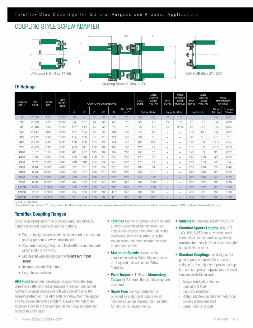
Torsiflex Coupling RangesSpecifically designed for the process pump, fan, blowers, compressors and general industrial markets.
• Plug-in design allows rapid installation and ensures that shaft alignment is always maintained.
• Standard couplings fully compliant with the requirements of API 610 / ISO 14691.
• Engineered version compliant with API 671 / ISO 10441.
• Incorporates anti-flail feature.
• Large hubs available.
AHX Hubs have been developed to accommodate large diameter shafts on process equipment. Large hubs cannot normally be used because of bolt withdrawal fouling the nearest obstruction. The AHX bolts withdraw from the spacer end thus eliminating this problem, allowing the hub to be mounted close to the equipment casing. Coupling sizes can be kept to a minimum.
• Torsiflex Couplings consist of 2 hubs and a factory assembled transmission unit. Installation involves fitting the hubs to the machinery shaft ends, introducing the transmission unit, then securing with the attachment screws.
• Maximum Speeds shown are for standard materials. When higher speeds are required, please consult Bibby Turboflex.
• Peak Torque of 1.75 and Momentary Torque of 2.7 times the stated ratings are accepted.
• Spark Free overload protection is provided as a standard feature on all Torsiflex couplings making them suitable for GAS ZONE environments.
• Suitable for temperatures of minus 20ºC.
• Standard Spacer Lengths 100, 125, 140, 180, & 250mm provide the most economical solution and are generally available from stock. Other spacer lengths are available to order.
• Standard Couplings are designed for general purpose applications and are suitable for the majority of process pump, fan, and compressor applications. Special versions available include:
- Torque overload protection- Limited end float- Electrical insulation- Bolted adapters suitable for high cyclic
torques & frequent start- Large Hubs (AHX style)
COUPLING STYLE SCREW ADAPTER
TF Ratings
CouplingSize TF
kW/ RPM
Rating Nm
MAXSPEEDRPM
COUPLING DIMENSIONSMAX
BORE
MassUnbored
(Solid)Hub (Kg)
MAXBORE
MassUnbored
(Solid)Hub (Kg)
MAXBORE
MassUnbored
(Solid)Hub (Kg)
Mass Transmission
Unit (Kg)
A A C C1 DMin DBSE
mm** Std AH Hub Large AH Hub AHX HubMass
Min LgExtra per 10 mm
17 0.018 170 25000 73 - 37 37 52 70 35 0.7 52 1.2 - - 0.6 0.02
27 0.028 270 20000 84 101 40 40 60 70 43 1.0 59 1.71 70 2.5 1.34 0.03
38 0.040 380 16500 107 117 45 45 76 70 55 1.8 75 3.05 83 3.8 1.95 0.04
140 0.147 1400 12000 127 154 75 95 101 100 73 4.9 – – 100 13.8 4.4 0.07
260 0.272 2600 10000 154 176 85 115 121 120 88 7.5 – – 120 21.6 7.7 0.1
400 0.419 4000 8500 176 208 105 135 144 140 105 13.8 – – 140 34 12.5 0.14
750 0.785 7500 7500 203 241 120 160 166 170 120 21 – – 165 56 20.5 0.23
1310 1.37 13100 6500 241 282 145 185 199 200 145 37 – – 190 89 35 0.27
1900 1.99 19000 5600 279 318 150 210 233 200 170 52 – – 220 130 46 0.33
2500 2.62 25000 5200 296 348 164 230 240 220 175 61 – – 240 169 58 0.4
3300 3.46 33000 4900 327 381 182 250 270 240 190 84 – – 260 220 78 0.49
6000 6.28 60000 4000 395 457 230 310 322 260 230 151 – – 320 378 123 0.73
7500 7.85 75000 4000 416 457 240 310 336 280 240 172 – – 320 378 143 0.73
8500 8.90 85000 3600 444 503 262 345 365 320 260 220 – – 360 532 190 0.96
11500 12.04 115000 3600 476 503 270 345 380 340 270 250 – – 360 532 228 1.06
12000 12.57 120000 3000 494 556 292 385 410 340 290 311 – – 400 721 255 1.38
16500 17.28 165000 3000 531 556 300 385 425 360 300 347 – – 400 721 306 1.38
New Sizes Highlited* Large Hub Boss Diameter. ** The inclusion of additional features such as packing rings, shims and/or electrical insulation will increase the minimum DBSE (Distance Between Shaft Ends).
AH Large H.B. (Size 17-38)
Coupling Sizes 17 Thru 12000
AHX HUB (Size 27-1200)

2www.bibbyturboflex.comP-1943-BB 1/18
w w w . b i b b y t u r b o f l e x . c o m
DO NOT SCALE IF IN DOUBT ASK
COPYRIGHT OF BIBBY TRANSMISSIONS, NOT TO BE COPIED OR COMMUNICATED TO A THIRD PARTY WITHOUT PERMISSION.
PROJECTION 3rd ANGLE
UNLESS OTHER WISE STATEDALL DIMENSIONS IN MILLIMETRES
ISO METRIC THREADS TO BS.3643 CLASS 6H/6g FITREMOVE SHARP EDGES
UNSPECIFIED RADII TO BE 0.8mm (0.032")BS, ISO, DIN STANDARDS ARE AT LATEST ISSUE
ALL MACHINED UNTOLERANCED DIMENSIONS +/- 0.25mm (0.010")ALL MACHINED SURFACES TO BE SQUARE AND CONCENTRIC TO DATUM 'A' WITHIN 0.025mm
(0.001") TIR.ALL SURFACES MACHINED 3.2 Micro Metre (125 Micro Inch) MAX
CANNON WAY, MILL ST WEST, DEWSBURY, WF13 1EHTEL. 01924 460801 FAX. 01924 457668
ron.cooper
TORSIFLEX 2LAH COUPLING RANGEDRG No: TFxxxx2LAH
MATERIAL:
REV: C
DESCRIPTION
DRAWN BY:CHECKED:
SCALE:PAPER SIZE:A33102-20-31CFRdedda sbuH XHA & sezis weNC
0102-4-21CFR041 ezis ot sdoMBA ORIGINAL ISSUE
ETADGISANCENOITPIRCSEDVER
O D
O A
CC DBSE
MAX BORE
Mass Unbored (Solid)
Hub (Kg)
MAX BORE
Mass Unbored (Solid)
Hub (Kg)
A A1 C C1 DMin
DBSE **Mass
Min LgExtra per 10 mm
140 0.147 1400 12000 154 154 85 95 117 100 84 7.5 100 13.8 5.1 0.07260 0.272 2600 10000 176 176 105 115 138 120 99 12.8 120 21.6 8 0.1400 0.419 4000 8500 203 204 120 135 158 140 113 19.2 140 34 13.2 0.14750 0.785 7500 7500 241 241 145 160 190 170 136 33.5 165 56 23.4 0.231310 1.37 13100 6500 282 282 150 185 230 2 164 50.6 190 89 39 0.271900 1.99 19000 5600 318 318 150 210 262 200 187 65.9 220 130 39 0.332230 2.34 22300 5600 318 318 160 210 262 220 187 70.1 220 130 45 0.332500 2.62 25000 5200 332 348 164 230 276 220 197 79 240 169 51 0.43200 3.35 32000 5200 348 348 175 230 292 240 209 95 240 169 63 0.43300 3.46 33000 4900 364 381 182 250 302 240 216 106 260 220 68 0.494800 5.03 48000 4900 381 381 200 250 310 260 221 123 260 220 79 0.586000 6.28 60000 4000 436 457 230 310 358 260 256 188 320 378 106 0.737500 7.85 75000 4000 457 457 240 310 370 280 264 210 320 378 123 0.738500 8.90 85000 3600 484 503 262 345 400 320 286 264 360 532 163 0.96
11500 12.04 115000 3600 503 503 270 345 415 340 296 295 360 532 190 1.0612000 12.57 120000 3000 540 556 292 385 444 340 317 366 400 721 216 1.3816500 17.28 165000 3000 556 556 300 385 456 360 326 395 400 721 250 1.38
** The inclusion of additional feature such as packing rings, shims and/or electrical insulation etc, would increase the minimum dimension by the appropriate amount
Mass (2LA)Transmission
Unit (Kg)*Coupling Size TF
KW/RPMRating
NM
MAX SPEED
RPMStd LAH Hub Std AHX Hub
COUPLING DIMENSIONS
AHX HUB (SIZE 140-16500)
OA
1
C1
MAX BORE
Unbored (Solid)
Hub (Kg)
MAX BORE
A A1 C C1 DMass Extra per
COUPLING DIMENSIONSCoupling Size TF
KW/RPMRating
NM
MAX SPEED
RPM dtS Standard AHX HubMin
DBSE**
Mass
LAH Hub
Unbored (Solid)
Hub (Kg)
Mass
Min Lg 10 mmm
Mass(2LA) Transmission
Unit (Kg)*
00
New sizes highlited.
COUPLING STYLE BOLTED ADAPTER
Service FactorsDriver Driven Service Factor (SF)
Turbines, Soft start motors
Steady Torque Eg. Centrifugal pumps
1.2
DOL (Direct On line) Start Motors
Fluctuating Torque Pumps, Rotary compressors
( frequent starts )
1.5( 2 )
DOL (Direct On line) Start Motors
Reciprocating Compressors 1 - 3 cylinders
3
DOL (Direct On line) Start Motors
Reciprocating Compressors4 - 6 cylinders
2
DOL (Direct On line) Start Motors
Reciprocating Compressors over 6 cylinders
1.5
DOL (Direct On line) Start Motors
Centrifugal Fans forced draught
1.5
DOL (Direct On line) Start Motors
Cooling Tower induced draught
2
For all other applications please contact Bibby Turboflex
Selection Procedure1. Select an appropriate service factor “SF”
2. Calculate rating = Power (kW) x SF/Speed (rpm)
3. Select a coupling with sufficient rating
4. Check hub bore is capable of accommodating shafts
5. Check Speed is within the maximum for the coupling selected
6. Specify required dynamic balance
7. Specify the distance between shaft ends and check this is not less than the minimum for the selected couplingEg. 90kW Direct on line electric motor driving a centrifugal pump at 3,000 rpm. Distance between shaft end = 140mmRating = 90 x 1.5 = 0.045kW/rpm 3000Selection TF0140L140 Screwed Adapter
Max hub bore = 73mm Standard HubMax hub bore = 100mm AHX Hub
orSelection TFO14OL14O Bolted AdapterMax hub bore = 84mm LAH HubMax hub bore = 100mm AHX Hub
AHX HUB (Size 140-16500)
Coupling Size TF
kW/ RPM
Rating Nm
MAX SPEED RPM
COUPLING DIMENSIONSMAX
BORE
Mass Unbored
(Solid) Hub (Kg)
MAX BORE
Mass Unbored
(Solid) Hub (Kg)
Mass Transmission Unit
(Kg)
A A1 C C1 DMin DBSE
mm** Std LAH Hub Standard AHX HubMass
Min LgExtra per 10 mm
140 0.147 1400 12000 154 154 85 95 117 100 84 7.5 100 13.8 5.1 0.07
260 0.272 2600 10000 176 176 105 115 138 120 99 12.8 120 21.6 8 0.1
400 0.419 4000 8500 203 204 120 135 158 140 113 19.2 140 34 13.2 0.14
750 0.785 7500 7500 241 241 145 160 190 170 136 33.5 165 56 23.4 0.23
1310 1.37 13100 6500 282 282 150 185 230 200 164 50.6 190 89 39 0.27
1900 1.99 19000 5600 318 318 150 210 262 200 187 65.9 220 130 39 0.33
2230 2.34 22300 5600 318 318 160 210 262 220 187 70.1 220 130 45 0.33
2500 2.62 25000 5200 332 348 164 230 276 220 197 79 240 169 51 0.4
3200 3.35 32000 5200 348 348 175 230 292 240 209 95 240 169 63 0.4
3300 3.46 33000 4900 364 381 182 250 302 240 216 106 260 220 68 0.49
4800 5.03 48000 4900 381 381 200 250 310 260 221 123 260 220 79 0.58
6000 6.28 60000 4000 436 457 230 310 358 260 256 188 320 378 106 0.73
7500 7.85 75000 4000 457 457 240 310 370 280 264 210 320 378 123 0.73
8500 8.90 85000 3600 484 503 262 345 400 320 286 264 360 532 163 0.96
11500 12.04 115000 3600 503 503 270 345 415 340 296 295 360 532 190 1.06
12000 12.57 120000 3000 540 556 292 385 444 340 317 366 400 721 216 1.38
16500 17.28 165000 3000 556 556 300 385 456 360 326 395 400 721 250 1.38
New Sizes Highlited* Large Hub Boss Diameter. ** The inclusion of additional features such as packing rings, shims and/or electrical insulation will increase the minimum DBSE (Distance Between Shaft Ends).

3 www.bibbyturboflex.com P-1943-BB 1/18
T o r s i f l e x D i s c C o u p l i n g s f o r G e n e r a l P u r p o s e a n d P r o c e s s A p p l i c a t i o n s
TYPE TFCFT COMPOSITE TUBE (“PLUG-IN”) COUPLINGS
SizeRating Max Bore
(mm)Applicable
Tube
Dimensions
Kw/RPM Nm A1 B(Tube OD) A C D
140 0.147 1400 73 T3/T4 147/192 107/157 127 95 101
260 0.272 2600 88 T4/ T5 198/246 157/207 154 115 121
400 0.419 4000 105 T4/T5/T6 198/246/302 157/207/269 176 135 144
750 0.785 7500 120 T5/T6 252/308 207/269 203 160 166
1310 1.37 13100 145 T6 313 269 241 185 199
1900 1.99 19000 170 T6/T7 325/410 269/350 279 210 233
2500 2.62 25000 175 T6/T7 345/430 260/350 296 230 240
3300 3.46 33000 190 T7/T8 430/550 350/471 327 250 270
6000 6.28 60000 230 T8 570 471 395 310 322
8500 8.9 85000 260 T8 570 471 444 345 365
12000 12.57 120000 290 T9 613 517 494 385 410
Single Span Configuration
Tube Ref.Max. DBSE (meters) @ rpm. Min. DBSE
(meters)3000 1500 1000 750
T3 2.6 3.7 4.5 5.2 0.8
T4 3.1 4.5 5.5 6.6 0.8
T5 3.6 5.1 6.3 7.3 0.8
T6 4.1 5.7 7.1 8.2 1
T7 4.4 6.6 7.7 8.9 1
T8 4.8 6.8 8.4 9.5 1.5
T9 5 7.1 8.7 9.9 1.5
Special features can be designed into the coupling to suit the application. Taper Lock bushes, thrust buttons for vertical applications, shrink discs, and seal removal pieces are common additions.
D
C
E
DBSE
E
C
A
D
C
E
DBSE
E
C
AD
C
E
DBSE
E
C
A
D
C
E
DBSE
E
C
A
Combined Anti-Flail system and Thrust Button. The Thrust Button is used to support the central spacer in vertical operation.
Taper Bush use in the hub at one end of the coupling to permit axial adjustment upon installation. Other clamp systems can also be incorporated into the designs. Please consult Bibby Turboflex.

4www.bibbyturboflex.comP-1943-BB 1/18
w w w . b i b b y t u r b o f l e x . c o m
Type TFCFT Composite Tube (“Plug-in”) CouplingsThe TFCFT range of composite tube disc couplings has been designed using the latest material technology- providing lower mass and greater strength. This type of unit was, originally, designed to meet the requirements of cooling towers but has since been adapted to meet the requirements of many alternative applications, specifically long vertical pump and marine drives. In addition to the disc coupling applications, Bibby Turboflex have developed the use of composite tubes in a number of other areas. The tubes have been designed and supplied for use in hovercraft fans, performance car drive shafts and high speed test beds. The tubes are filament wound on accurate mandrels using computer controlled machinery. The resulting tube is cured whilst on the mandrel. This process leads to high accuracy with regard to tube dimensions, roundness and straightness all of which aid in the ability of Bibby Turboflex to supply an extremely high quality product.
Purpose developed software enables Bibby Turboflex to offer tube with fibre windings at angles adjusted to give the optimum performance for specific lateral critical, torque and torsional stiffness requirements.
Bibby Turboflex have the option to wind tubes using a variety of fibres, each of which give specific advantages.
• Carbon Fibre- This is the principle material giving a high strength/low mass option for the tubes. This is considered as the standard for the TFCFT range of couplings.
• Glass Fibre - Glass fibre offers a low cost solution for many applications of moderate length. The mass to stiffness ratio is less favourable than that for Carbon Fibre but such units do have applications to which they are ideally suited.
• Carbon/Glass Mix- The fibre winding approach adopted by Bibby Turboflex enables us to combine these materials to use the advantages of both to give the optimum solution for a specific application.
• High Modulus Fibre- Due to its high cost and limited availability, the use of high modulus fibre is generally only adopted for the more extreme applications to give optimum solutions.
The tubes are wrapped in a pigment treated glass fibre layer, which serves to protect them against physical damage and Ultra-Violet degradation.
Type TFCFT Composite Tube (“Plug-in”) Couplings
Cooling Tower Fan Drives
Bibby Turboflex composite shaft couplings are perfectly suited for driving cooling tower fans. Their ability to operate over long lengths without central bearings, combined with their inherently low mass and generous misalignment capacity, keeps maintenance of the equipment to a minimum. The maintenance free nature of the Bibby Turboflex disc couplings means the units become virtually “fit & forget”.
The design is such as to make site assembly as easy as possible. The units can be supplied in standard carbon steel with a variety of protective coatings or, if required, in stainless steel.
Vertical Pump Drives
Bibby Turboflex composite shaft couplings can be employed to great advantage in deep well pump applications such as encountered in water & sewage pumping stations. Their ability to cover long spans without the need for central bearings and their inherent low mass can considerably reduce maintenance costs on units.
This is something advantageous on remote operated or inaccessible plants especially in conjunction with the “fit & forget” nature of the Bibby Turboflex disc couplings.
Material & coatings can be varied to suit the requirements of particular applications.
Axial length adjustment can be incorporated in the couplings in various ways which, when coupled with the generous misalignment capacity and ease of assembly design, can reduce installation time.
When necessary, thrust pins can be added to the unit to support the mass of the central spacer.
Marine Drives
Bibby Turboflex composite shaft couplings have been successfully utilised in marine applications for both ships & hovercrafts.
The low mass and minimal vibration levels, together with the ability to handle long spans without support bearings, have proved a benefit in many such applications.
Special Applications
Bibby Turboflex disc couplings with composite spacer shafts are used in many special applications. Their low mass & low inertia, coupled with the ability to adjust the torsional & lateral characteristics of the shaft during manufacture, have made them applicable for many cases where conventional couplings have been inappropriate. Whilst the application for these shafts is as wide as that for couplings themselves, particular success has been found in marine applications, automobile drives and high speed engine test beds.
Whilst the composite shafting is primarily intended for use with Bibby Turboflex disc couplings, it can equally well be incorporated into any other of our wide range of products.
5 www.bibbyturboflex.com P-1943-BB 1/18
T o r s i f l e x D i s c C o u p l i n g s f o r G e n e r a l P u r p o s e a n d P r o c e s s A p p l i c a t i o n s
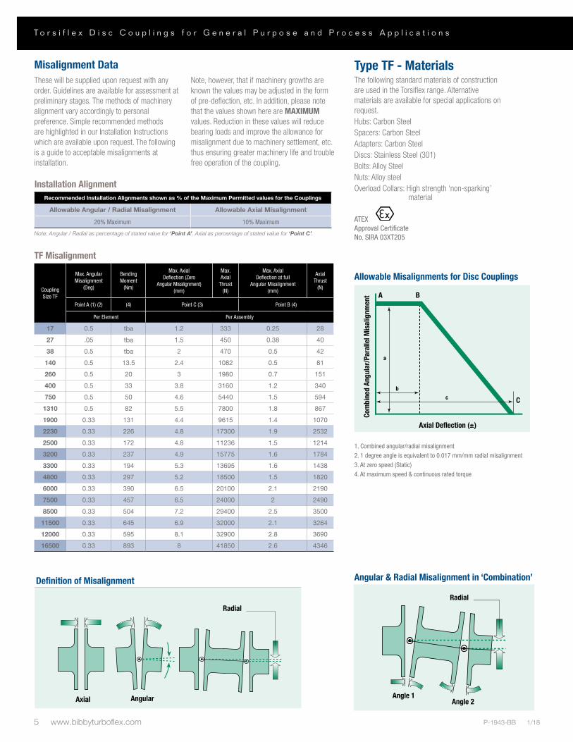
Installation AlignmentRecommended Installation Alignments shown as % of the Maximum Permitted values for the Couplings
Allowable Angular / Radial Misalignment Allowable Axial Misalignment
20% Maximum 10% Maximum
Note: Angular / Radial as percentage of stated value for ‘Point A’. Axial as percentage of stated value for ‘Point C’.
Misalignment DataThese will be supplied upon request with any order. Guidelines are available for assessment at preliminary stages. The methods of machinery alignment vary accordingly to personal preference. Simple recommended methods are highlighted in our Installation Instructions which are available upon request. The following is a guide to acceptable misalignments at installation.
Note, however, that if machinery growths are known the values may be adjusted in the form of pre-deflection, etc. In addition, please note that the values shown here are MAXIMUM values. Reduction in these values will reduce bearing loads and improve the allowance for misalignment due to machinery settlement, etc. thus ensuring greater machinery life and trouble free operation of the coupling.
1. Combined angular/radial misalignment2. 1 degree angle is equivalent to 0.017 mm/mm radial misalignment3. At zero speed (Static)4. At maximum speed & continuous rated torque
Definition of Misalignments Angular & Radial Misalignment in "Combination"
Axial Angular
Radial
Angle 1Angle 2
Radial
TF Misalignment
CouplingSize TF
Max. Angular Misalignment
(Deg)
Bending Moment
(Nm)
Max. Axial Deflection (Zero
Angular Misalignment) (mm)
Max. Axial
Thrust (N)
Max. Axial Deflection at full
Angular Misalignment (mm)
Axial Thrust
(N)
Point A (1) (2) (4) Point C (3) Point B (4)
Per Element Per Assembly
17 0.5 tba 1.2 333 0.25 28
27 .05 tba 1.5 450 0.38 40
38 0.5 tba 2 470 0.5 42
140 0.5 13.5 2.4 1082 0.5 81
260 0.5 20 3 1980 0.7 151
400 0.5 33 3.8 3160 1.2 340
750 0.5 50 4.6 5440 1.5 594
1310 0.5 82 5.5 7800 1.8 867
1900 0.33 131 4.4 9615 1.4 1070
2230 0.33 226 4.8 17300 1.9 2532
2500 0.33 172 4.8 11236 1.5 1214
3200 0.33 237 4.9 15775 1.6 1784
3300 0.33 194 5.3 13695 1.6 1438
4800 0.33 297 5.2 18500 1.5 1820
6000 0.33 390 6.5 20100 2.1 2190
7500 0.33 457 6.5 24000 2 2490
8500 0.33 504 7.2 29400 2.5 3500
11500 0.33 645 6.9 32000 2.1 3264
12000 0.33 595 8.1 32900 2.8 3690
16500 0.33 893 8 41850 2.6 4346
Type TF - MaterialsThe following standard materials of construction are used in the Torsiflex range. Alternative materials are available for special applications on request.Hubs: Carbon SteelSpacers: Carbon SteelAdapters: Carbon SteelDiscs: Stainless Steel (301)Bolts: Alloy SteelNuts: Alloy steelOverload Collars: High strength ‘non-sparking’ material
ATEX Approval Certificate No. SIRA 03XT205
Definition of Misalignments Angular & Radial Misalignment in "Combination"
Axial Angular
Radial
Angle 1Angle 2
Radial
Definition of Misalignment
Definition of Misalignments Angular & Radial Misalignment in "Combination"
Axial Angular
Radial
Angle 1Angle 2
Radial
AngularAxial
Definition of Misalignments Angular & Radial Misalignment in "Combination"
Axial Angular
Radial
Angle 1Angle 2
Radial
Radial
Angular & Radial Misalignment in ‘Combination’Definition of Misalignments Angular & Radial Misalignment in "Combination"
Axial Angular
Radial
Angle 1Angle 2
Radial
Radial
Definition of Misalignments Angular & Radial Misalignment in "Combination"
Axial Angular
Radial
Angle 1Angle 2
Radial
Definition of Misalignments Angular & Radial Misalignment in "Combination"
Axial Angular
Radial
Angle 1Angle 2
Radial
Angle 1Angle 2
Com
bine
d An
gula
r/Pa
ralle
l Mis
alig
nmen
t
Axial Deflection (±)
b
a
c C
A B
Allowable Misalignments for Disc Couplings

6www.bibbyturboflex.comP-1943-BB 1/18
w w w . b i b b y t u r b o f l e x . c o m
Torsiflex Couplings
NOW AVAILABLE WITH TORSI-LOCK® HUBSTorsi-Lock provides the ease of a slip fit with the power of a shrink fit
C C
D (DBSE)
B
ØH ØA
Torsi-Lock can be specified for one or both hubs and sized to accommodate a variety of shaft diameters.
Altra Couplings has responded to industry demand for a cold-install hub that provides the secure torque transmission and balance repeatability of an interference fit. We’ve combined shaft locking devices with Torsiflex to provide a pre-engineered solution that meets the balance requirements of API 610.
• Cold Install means NO HOT WORK PERMITS, providing added safety and productivity in hazardous environments
• Easy, repeatable removal and installation• Eliminates fretting of hub to shaft• Compensates for variances in shaft spacing – slip on and fix in the needed location• May be used with keyed or keyless shafts (half key recommended with keyed shafts)• Fully pre-engineered solution - Correct material selection to prevent permanent shrink of hub to shaft - Lightest weight locking device/hub combination selected - Hub and locking device balanced and
match marked to assure optimum balance performance.
For more information visit www.bibbyturboflex.com

www.bibbyturboflex.com
The Brands of Altra Industrial Motion
Couplings
Ameridriveswww.ameridrives.com
Bibby Turbo� ex www.bibbyturbo� ex.com
Guardian Couplingswww.guardiancouplings.com
Hucowww.huco.com
Lami� ex Couplingswww.lami� excouplings.com
Stromag www.stromag.com
TB Wood’swww.tbwoods.com
Geared Cam Limit Switches
Stromagwww.stromag.com
Electric Clutches & Brakes
Inertia Dynamicswww.idicb.com
Matrixwww.matrix-international.com
Stromagwww.stromag.com
Warner Electricwww.warnerelectric.com
Linear Products
Warner Linearwww.warnerlinear.com
Engineered Bearing Assemblies
Kilianwww.kilianbearings.com
Heavy Duty Clutches & Brakes
Industrial Clutchwww.indclutch.com
Twi� exwww.twi� ex.com
Stromagwww.stromag.com
Svendborg Brakeswww.svendborg-brakes.com
Wichita Clutchwww.wichitaclutch.com
Belted Drives
TB Wood’s www.tbwoods.com
Gearing
Bauer Gear Motorwww.bauergears.com
Boston Gearwww.bostongear.com
Delroyd Worm Gearwww.delroyd.com
Nuttall Gearwww.nuttallgear.com
Overrunning Clutches
Formsprag Clutchwww.formsprag.com
Marland Clutchwww.marland.com
Stieberwww.stieberclutch.com
Bibby Turbo� ex Facilities
Europe
Cannon Way, DewsburyWest Yorkshire WF13 1EH - England+44(0) 1924 460801
Disc, Gear, Grid Couplings, Overload Clutches
Africa
Unit 11, Middle Park, Cnr. Craig & Dormehl RoadsAnderbolt, Boksburg, P.O. Box 16524Atlasville, 1465 - South Africa+27(0) 11 918-4270
Disc, Gear, Grid Couplings, Overload Clutches
Neither the accuracy nor completeness of the information contained in this publication is guaranteed by the company and may be subject to change in its sole discretion. The operating and performance characteristics of these products may vary depending on the application, installation, operating conditions and environmental factors. The company’s terms and conditions of sale can be viewed at http://www.altramotion.com/terms-and-conditions/sales-terms-and-conditions. These terms and conditions apply to any person who may buy, acquire or use a product referred to herein, including any person who buys from a licensed distributor of these branded products.
©2018 by Bibby Turbo� ex LLC. All rights reserved. All trademarks in this publication are the sole and exclusive property of Bibby Turbo� ex LLC or one of its af� liated companies.
P-1943-BB 1/18