Coupling of Regional and Local Circulation Models ADCIRC · PDF fileCoupling of Regional and...
14
ERDC/CHL CHETN-IV-42 June 2002 Coupling of Regional and Local Circulation Models ADCIRC and M2D by Adele Militello and Alan K. Zundel PURPOSE: The Coastal and Hydraulics Engineering Technical Note (CHETN) described herein provides guidance on coupling the regional circulation model, Advanced Circulation (ADCIRC), with the local circulation model M2D. Coupling of models is an efficient and accurate means of calculating water level and current on a local domain, such as at and around an inlet. This CHETN also serves as a tutorial for coupling the two models within the Surface-Water Modeling System (SMS). BACKGROUND: Circulation modeling at tidal inlets requires accurate boundary conditions at the seaward edge of the domain. Regional models developed by the Coastal Inlets Research Program (CIRP) provide information that can be applied as boundary conditions for local (project scale) models. Examples of regional models available from the CIRP are Long Island, NY, southwest Washington, northern California, east coast of Florida, and the Maryland and Delaware coast. Water levels from solutions of these regional models can be applied as boundary conditions for local projects. Large-scale physical oceanographic processes such as the tide and storms can be represented in regional models and the information cascaded locally by furnishing boundary (driving) conditions to meet project analysis requirements. Also, multiple projects with great detail can be included within a computationally efficient regional domain (Militello, Kraus, and Brown 2000). Benefits include automatic calculation of mutual interactions among projects, such as multiple inlets sharing the same bay or lagoonal system, and the availability of baseline information from which new projects can be added. In addition, duplication of effort can be avoided, increasing efficiency and cost-effectiveness. Engineering applications require numerous simulations with modified grids to determine the consequences of project alternatives. An efficient means of conducting multiple simulations is to apply a local model, which eliminates the computational overhead of a large domain. By coupling regional and local models, the local model can propagate hydrodynamic conditions on the boundaries calculated by the regional model into its smaller domain. Coupling of the models is accomplished by passing time series of water level obtained from the regional model solution to the local model as boundary conditions. Because the boundary conditions for the local model were calculated on a regional domain, they contain spatial variations that preserve such features as tidal phase, surge distribution, and wind setup or setdown. Other boundary conditions or input, such as river discharge or wind, can be specified for the local model as required by the project. The coupled modeling approach is advantageous because the local model can apply ADCIRC- calculated water levels from previous studies as boundary conditions if they are available for the time period of interest. Alternatively, ADCIRC can be run for the time intervals required for the study, and then the local model can be applied. In both situations, modifications to the local grid can be easily made for project alternatives without the necessity of multiple simulations with the large
Transcript of Coupling of Regional and Local Circulation Models ADCIRC · PDF fileCoupling of Regional and...
ERDC/CHL CHETN-IV-42 June 2002
Coupling of Regional and Local Circulation Models ADCIRC and M2D
by Adele Militello and Alan K. Zundel
PURPOSE: The Coastal and Hydraulics Engineering Technical Note (CHETN) described herein provides guidance on coupling the regional circulation model, Advanced Circulation (ADCIRC), with the local circulation model M2D. Coupling of models is an efficient and accurate means of calculating water level and current on a local domain, such as at and around an inlet. This CHETN also serves as a tutorial for coupling the two models within the Surface-Water Modeling System (SMS). BACKGROUND: Circulation modeling at tidal inlets requires accurate boundary conditions at the seaward edge of the domain. Regional models developed by the Coastal Inlets Research Program (CIRP) provide information that can be applied as boundary conditions for local (project scale) models. Examples of regional models available from the CIRP are Long Island, NY, southwest Washington, northern California, east coast of Florida, and the Maryland and Delaware coast. Water levels from solutions of these regional models can be applied as boundary conditions for local projects. Large-scale physical oceanographic processes such as the tide and storms can be represented in regional models and the information cascaded locally by furnishing boundary (driving) conditions to meet project analysis requirements. Also, multiple projects with great detail can be included within a computationally efficient regional domain (Militello, Kraus, and Brown 2000). Benefits include automatic calculation of mutual interactions among projects, such as multiple inlets sharing the same bay or lagoonal system, and the availability of baseline information from which new projects can be added. In addition, duplication of effort can be avoided, increasing efficiency and cost-effectiveness. Engineering applications require numerous simulations with modified grids to determine the consequences of project alternatives. An efficient means of conducting multiple simulations is to apply a local model, which eliminates the computational overhead of a large domain. By coupling regional and local models, the local model can propagate hydrodynamic conditions on the boundaries calculated by the regional model into its smaller domain. Coupling of the models is accomplished by passing time series of water level obtained from the regional model solution to the local model as boundary conditions. Because the boundary conditions for the local model were calculated on a regional domain, they contain spatial variations that preserve such features as tidal phase, surge distribution, and wind setup or setdown. Other boundary conditions or input, such as river discharge or wind, can be specified for the local model as required by the project. The coupled modeling approach is advantageous because the local model can apply ADCIRC-calculated water levels from previous studies as boundary conditions if they are available for the time period of interest. Alternatively, ADCIRC can be run for the time intervals required for the study, and then the local model can be applied. In both situations, modifications to the local grid can be easily made for project alternatives without the necessity of multiple simulations with the large

Report Documentation Page Form ApprovedOMB No. 0704-0188
Public reporting burden for the collection of information is estimated to average 1 hour per response, including the time for reviewing instructions, searching existing data sources, gathering andmaintaining the data needed, and completing and reviewing the collection of information. Send comments regarding this burden estimate or any other aspect of this collection of information,including suggestions for reducing this burden, to Washington Headquarters Services, Directorate for Information Operations and Reports, 1215 Jefferson Davis Highway, Suite 1204, ArlingtonVA 22202-4302. Respondents should be aware that notwithstanding any other provision of law, no person shall be subject to a penalty for failing to comply with a collection of information if itdoes not display a currently valid OMB control number.
1. REPORT DATE JUN 2002
2. REPORT TYPE N/A
3. DATES COVERED -
4. TITLE AND SUBTITLE Coupling of Regional and Local Circulation Models ADCIRC and M2D
5a. CONTRACT NUMBER
5b. GRANT NUMBER
5c. PROGRAM ELEMENT NUMBER
6. AUTHOR(S) Militello, Adele, and Zundel, Alan K.
5d. PROJECT NUMBER
5e. TASK NUMBER
5f. WORK UNIT NUMBER
7. PERFORMING ORGANIZATION NAME(S) AND ADDRESS(ES) US Army Corps of Engineers, Engineer Research and DevelopmentCenter, Coastal and Hydraulics Laboratory, Vicksburg, MS
8. PERFORMING ORGANIZATIONREPORT NUMBER
9. SPONSORING/MONITORING AGENCY NAME(S) AND ADDRESS(ES) 10. SPONSOR/MONITOR’S ACRONYM(S)
11. SPONSOR/MONITOR’S REPORT NUMBER(S)
12. DISTRIBUTION/AVAILABILITY STATEMENT Approved for public release, distribution unlimited
13. SUPPLEMENTARY NOTES The original document contains color images.
14. ABSTRACT This Coastal and Hydraulics Engineering Technical Note (CHETN) described provides guidance oncoupling the regional circulation model, Advanced Circulation (ADCIRC), with the local circulation modelM2D. Coupling of models is an efficient and accurate means of calculating water level and current on alocal domain, such as at and around an inlet. This CHETN also serves as a tutorial for coupling the twomodels within the Surface-Water Modeling System (SMS).
15. SUBJECT TERMS
16. SECURITY CLASSIFICATION OF: 17. LIMITATION OF ABSTRACT
UU
18. NUMBEROF PAGES
13
19a. NAME OFRESPONSIBLE PERSON
a. REPORT unclassified
b. ABSTRACT unclassified
c. THIS PAGE unclassified
Standard Form 298 (Rev. 8-98) Prescribed by ANSI Std Z39-18
ERDC/CHL CHETN-IV-42 June 2002
2
regional model. This approach minimizes the time required for the user to work with the regional finite-element model. This CHETN describes coupling of the regional oceanographic model ADCIRC (Luettich, Westerink, and Scheffner 1992) with the local model M2D (Militello, Zundel, and Buonaiuto, in preparation; Militello 1998). Automated coupling of the models is implemented within the SMS (Zundel 2002) through interpolation of ADCIRC-calculated water levels to M2D boundary cells (Militello and Zundel, in preparation). In the following, the circulation models are introduced and information on coupling them within the SMS is provided. An example of automated coupling is then given. ADCIRC: The two-dimensional depth-integrated, finite-element circulation model ADCIRC was developed for large-scale applications within which fine detail can be specified for local areas. ADCIRC has great flexibility in its element sizes, which is convenient for creating calculation meshes in which coarser resolution is specified in areas away from the study site to improve computation time. Resolution can be increased in areas of strong bathymetric gradients, such as over the continental shelf, to maintain computational accuracy. Features of ADCIRC include multiple forcing options, robust wetting and drying, hot start capability, calculation in spherical or Cartesian coordinates, choice of bottom-stress models, internal harmonic analysis, and user-specified global and station output. Forcing can be imposed by tidal constituents, water-surface elevation time series, flow-rate time series, wind stress, atmospheric pressure, and wave stress. Information on these and other model features are provided in an online ADCIRC User’s Guide that can be accessed on the internet at http://www.unc.edu/depts/ marine/C_CATS/adcirc/document/ADCIRC_main_frame.html. The Web site also lists ADCIRC-related publications on research and model applications. Through the large-domain capability of ADCIRC, processes on multiple spatial and temporal scales can be calculated. For example, nonlinear tidal propagation over the continental shelf is a large-scale process that can be combined in the same simulation as flow though a tidal inlet. Calculated water level and current velocity values represent the response of the combined processes on all scales included in the simulation. Thus, transfer of water levels calculated with ADCIRC to a local-domain model preserves the description of the processes at the boundaries of the local model. M2D: The two-dimensional depth-integrated finite-difference hydrodynamic model M2D was developed for project-scale applications, such as inlets, navigation channels, and bays. M2D operates on an orthogonal rectilinear grid in which cell side lengths can vary. Greater resolution can be specified in areas where it is needed, such as at structures and areas of changing depth (channels, shoals, wetlands and marshes), and special target areas of interest. In addition, the grid can be aligned as needed for a specific application. For example, for an inlet application, the grid can be aligned with its x or y axis oriented along the principal axis of the channel. This capability for grid rotation provides flexibility for setting the orientation to maximize efficiency and accuracy. Features of M2D include robust flooding and drying, wave-stress forcing, wind-speed dependent (time-varying) wind-drag coefficient, variably-spaced bottom-friction coefficient, efficient grid storage in memory, hot start capability, and user-specified global and station output. M2D can be
ERDC/CHL CHETN-IV-42 June 2002
3
forced with any combination of water level, tidal constituents, flow rate, wave stresses, and wind. Model output is written in formats convenient for importing into commercially available plotting packages. The rectilinear grid of M2D is convenient to create and modify as compared to a finite-element (irregular) mesh, especially for those with modest experience in modeling or for fast-track projects. Also, sediment-transport and morphology change algorithms, presently under development in the CIRP, are readily and naturally accommodated on a rectilinear grid. MODEL COUPLING: Coupling of ADCIRC and M2D takes place through water-level forcing boundary conditions specified for M2D. Time series of water level calculated by ADCIRC serve as forcing information for M2D. The basic procedure for model coupling is:
a. Run ADCIRC model for simulation interval. b. Specify ADCIRC water-level files as boundary forcing for M2D. c. Extract water-level values from ADCIRC solution to be applied as forcing for M2D. d. Run M2D for simulation interval.
Coupling of the two models is automated within the SMS. Specification of ADCIRC water-level files and extraction of values for M2D are conducted based on an existing ADCIRC simulation and the boundary condition settings for M2D. The SMS interpolates the ADCIRC-calculated values to M2D cell centers where water level is specified. For accurate calculation of boundary values for M2D, the ADCIRC mesh must contain adequate resolution near the M2D forcing boundary. If the ADCIRC mesh resolution is too coarse, then the interpolation of water-level values to the M2D boundary cells may be inaccurate or biased, depending on the placement of the ADCIRC computational nodes relative to the M2D cell centers. Appropriate resolution of the ADCIRC mesh will depend on the domain and requirements of a study. Thus, the user must evaluate what resolution is necessary. Figure 1 shows an ADCIRC mesh at an M2D boundary. The models were coupled for a hydro-dynamic and sediment transport study at Bay Center, WA (Militello 2002). ADCIRC computational nodes are located at the vertices of the triangles. Water-level forcing values for M2D are supplied at the centers of the M2D boundary cells, denoted by the red dots. The fine resolution of the ADCIRC mesh relative to the M2D grid in this example was deemed necessary because there was significant variation in tidal phase across the boundary. This level of detail in the ADCIRC calculations preserved the tidal phase over the M2D boundary, resulting in accurate calculations on the local (M2D) domain. AUTOMATED COUPLING WITHIN SMS: The SMS contains model-specific interfaces for both ADCIRC and M2D. These interfaces provide a suite of tools for finite-difference grid and finite-element mesh development, control file setup, boundary condition specification, and grid/mesh quality checks. Runs can be launched from within the SMS and results loaded for post-processing and visualization. To take advantage of the efficiency of running local models, SMS includes tools to simplify extraction of boundary condition data from the regional solution at the local model boundary locations. The extraction process for creation of boundary conditions for the local model relies on the existence of a regional model with a solution. Once water-level values are obtained from the

ERDC/CHL CHETN-IV-42 June 2002
4
ADCIRC node
M2D cell center
Triangles: ADCIRC meshRectangles: M2D grid
ADCIRC node
M2D cell center
Triangles: ADCIRC meshRectangles: M2D grid
Figure 1. ADCIRC nodes and M2D cells along a boundary regional model, SMS interpolates them to the centers of the M2D forcing boundary cells. In setting up a simulation for the local model, the user specifies the location for boundary conditions by means of a cell string. A cell string is a list of cells where, in this case, the water-surface elevation (WSE) will be forced. The boundary condition is applied to a cell string by selecting from a list of supported boundary conditions, as shown in Figure 2.
Figure 2. M2D Boundary Conditions dialog
ERDC/CHL CHETN-IV-42 June 2002
5
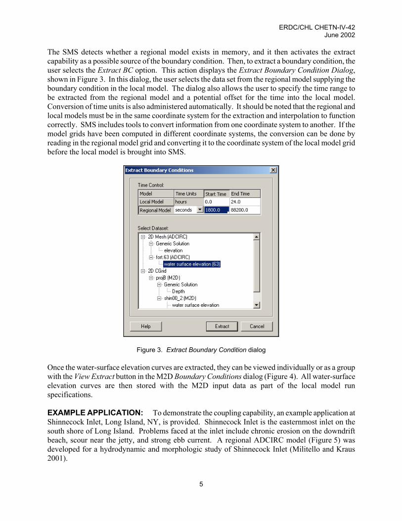
The SMS detects whether a regional model exists in memory, and it then activates the extract capability as a possible source of the boundary condition. Then, to extract a boundary condition, the user selects the Extract BC option. This action displays the Extract Boundary Condition Dialog, shown in Figure 3. In this dialog, the user selects the data set from the regional model supplying the boundary condition in the local model. The dialog also allows the user to specify the time range to be extracted from the regional model and a potential offset for the time into the local model. Conversion of time units is also administered automatically. It should be noted that the regional and local models must be in the same coordinate system for the extraction and interpolation to function correctly. SMS includes tools to convert information from one coordinate system to another. If the model grids have been computed in different coordinate systems, the conversion can be done by reading in the regional model grid and converting it to the coordinate system of the local model grid before the local model is brought into SMS.
Figure 3. Extract Boundary Condition dialog
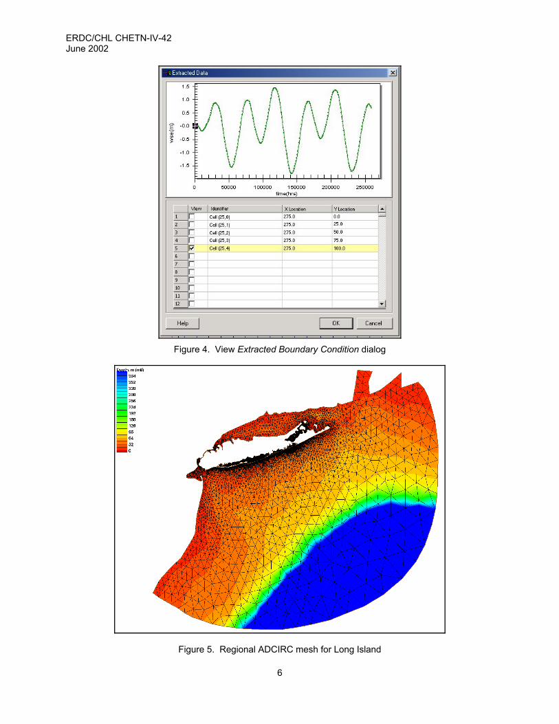
Once the water-surface elevation curves are extracted, they can be viewed individually or as a group with the View Extract button in the M2D Boundary Conditions dialog (Figure 4). All water-surface elevation curves are then stored with the M2D input data as part of the local model run specifications. EXAMPLE APPLICATION: To demonstrate the coupling capability, an example application at Shinnecock Inlet, Long Island, NY, is provided. Shinnecock Inlet is the easternmost inlet on the south shore of Long Island. Problems faced at the inlet include chronic erosion on the downdrift beach, scour near the jetty, and strong ebb current. A regional ADCIRC model (Figure 5) was developed for a hydrodynamic and morphologic study of Shinnecock Inlet (Militello and Kraus 2001).
ERDC/CHL CHETN-IV-42 June 2002
6
Figure 4. View Extracted Boundary Condition dialog
Figure 5. Regional ADCIRC mesh for Long Island

ERDC/CHL CHETN-IV-42 June 2002
7
Global water-surface elevations from the Militello and Kraus (2001) study were saved every 0.5 hr. An M2D grid was developed for Shinnecock Inlet and Bay, as well as a portion of the nearshore area. Figure 6 shows the M2D grid overlaid on the local area of the ADCIRC mesh. Water levels from the global ADCIRC solution file furnish forcing for the seaward M2D boundary.
Figure 6. M2D grid shown with ADCIRC mesh at Shinnecock Bay and Inlet M2D and ADCIRC must be in the same coordinate system for the coupling. Because M2D requires a Cartesian coordinate system, it is preferable to convert the ADCIRC grid from spherical to Cartesian coordinates (if it has not already been saved in the same coordinate system as M2D). If a conversion is required, the easiest approach is to load the ADCIRC grid first and convert it to the same coordinate system that the M2D grid lies in. Then, the M2D project can be loaded into the SMS. Alternatively, ADCIRC can be saved in the required Cartesian coordinate system and loaded into SMS either before or after M2D. For this example, ADCIRC and M2D have both been saved in New York State Plane, Long Island, with units of meters. An ADCIRC global solution file must be loaded into the SMS before water-level values can be specified at the M2D boundary. The ADCIRC solution can be loaded into the data browser in the mesh module. Once the ADCIRC solution has been loaded, coupling of M2D with ADCIRC can take place. To extract ADCIRC water levels from the global solution to apply as M2D boundary conditions, the user must switch from the SMS mesh module to the Cartesian grid module. A cell string must be defined along the seaward and lateral boundaries where the extracted water-level values will be

ERDC/CHL CHETN-IV-42 June 2002
8
applied. To create the cell string, click on the Create Cellstring tool. Next, click on an end cell of the cell string. Holding down the shift key, click each corner along the boundary until all boundary cells are included in the cell string, and press Enter. Figure 7 shows the newly-created cell string in red.
Figure 7. M2D grid with seaward boundary cell string shown in red The next step will define the cell string as an extracted water-level forcing boundary. Click on the Select Cellstring tool and then double click on the box that lies in the center of the new cell string. This action will activate the M2D Boundary Conditions dialog shown in Figure 2. Click on WSE-forcing on the left side of the dialog. This action enables the user to choose the type of water-level forcing information that M2D will apply. Click on Extract from data set and then click the Extract BC button to bring up the Extract Boundary Conditions dialog. There are two areas of this dialog, with the top portion being the Time Control and the bottom portion being the Select Dataset dialog. The Time Control lets the user select a portion of the available solution that can be extracted. The Select Dataset provides a display of the data sets. For Time Control, the SMS will automatically set the information extraction to take place from the beginning of the available solution file. The length of the information extracted (in time) will correspond to the specified duration of the M2D simulation. The user can select other portions of the solution if needed by clicking on Regional Model, then editing the starting and ending times.
ERDC/CHL CHETN-IV-42 June 2002
9
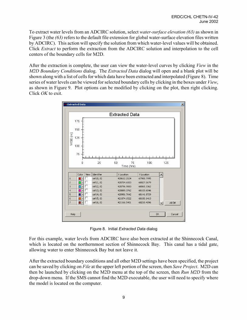
To extract water levels from an ADCIRC solution, select water-surface elevation (63) as shown in Figure 3 (the (63) refers to the default file extension for global water-surface elevation files written by ADCIRC). This action will specify the solution from which water-level values will be obtained. Click Extract to perform the extraction from the ADCIRC solution and interpolation to the cell centers of the boundary cells for M2D. After the extraction is complete, the user can view the water-level curves by clicking View in the M2D Boundary Conditions dialog. The Extracted Data dialog will open and a blank plot will be shown along with a list of cells for which data have been extracted and interpolated (Figure 8). Time series of water levels can be viewed for selected boundary cells by clicking in the boxes under View, as shown in Figure 9. Plot options can be modified by clicking on the plot, then right clicking. Click OK to exit.
Figure 8. Initial Extracted Data dialog
For this example, water levels from ADCIRC have also been extracted at the Shinnecock Canal, which is located on the northernmost section of Shinnecock Bay. This canal has a tidal gate, allowing water to enter Shinnecock Bay but not leave it. After the extracted boundary conditions and all other M2D settings have been specified, the project can be saved by clicking on File at the upper left portion of the screen, then Save Project. M2D can then be launched by clicking on the M2D menu at the top of the screen, then Run M2D from the drop-down menu. If the SMS cannot find the M2D executable, the user will need to specify where the model is located on the computer.

ERDC/CHL CHETN-IV-42 June 2002
10
Figure 9. Extracted Data dialog with two water-level curves
Selected results of the M2D simulation at ebb and flood tide are provided as an example solution. Water level contours and current velocity vectors are shown in Figure 10 during ebb tide. White areas in the bay denote dry cells. This snapshot was taken near the end of an ebb cycle and the tidal current in the coastal ocean has started to reverse. Current speed contours and direction vectors during flood at the inlet and bay are shown in Figure 11. The dry areas of the bay are smaller than those in Figure 10, indicating higher water level. Strong currents are formed within the inlet and at the Shinnecock Canal. In this snapshot, the coastal tidal current is flowing from east to west. This flow pattern along the coast can only be obtained by specification of varying water levels along the ocean boundary. DISCUSSION: This CHETN has described coupling of the regional and local circulation models ADCIRC and M2D within the SMS. This type of coupling is advantageous for local applications in which multiple simulations are required. The SMS automates the model coupling by extracting water-level values from global ADCIRC solutions, interpolating them to M2D boundary cell centers, and saving the time series as M2D forcing input files. If solutions from previous ADCIRC simulations are available, the user may not have to run the regional model, but can apply existing solutions as boundary conditions.

ERDC/CHL CHETN-IV-42 June 2002
11
Figure 10. Water level and current vectors at ebb tide over entire domain
Figure 11. Current speed and direction at flood tide over inlet and bay

ERDC/CHL CHETN-IV-42 June 2002
12
Coupling of ADCIRC and M2D has been conducted for Shinnecock Inlet, NY, and at Bay Center, WA (Militello 2002; Militello, Parry, and Arden 2002). Shinnecock has a tide range of about 1.5 m (5 ft) and a flood shoal that becomes inundated and exposed during the tidal cycle. Bay Center is located in Willapa Bay, which has a tide range of about 2.7 m (9 ft). Approximately half of Willapa Bay dries during low tide. In both cases, the water-level values transferred from ADCIRC to the local M2D model specified high-quality boundary conditions and included tidal phase. This boundary specification enabled accurate representation of processes at both locations. ADDITIONAL INFORMATION: Questions about this CHETN can be addressed to Dr. Adele Militello at (707) 444-2173 or [email protected], to Dr. Alan K. Zundel at (801) 378-2812 or [email protected], or to Ms. Mary A. Cialone at (601) 634-2179 or Mary.A.Cialone@erdc. usace.army.mil. This CHETN was produced under the Inlet Modeling System work unit of the Coastal Inlets Research Program. For information about the Coastal Inlets Research Program, please contact the Program Manager, Dr. Nicholas C. Kraus, at (601) 634-2016 or Nicholas.C.Kraus@erdc. usace.army.mil. This technical note should be cited as follows:
Militello, A., and Zundel, A. K. (2002). “Coupling of regional and local circulation models ADCIRC and M2D,” ERDC/CHL CHETN-IV-42, U.S. Army Engineer Research and Development Center, Vicksburg, MS.
REFERENCES Luettich, R. A., Westerink, J. J., and Scheffner, N. W. (1992). “ADCIRC: An advanced three-dimensional circulation
model for shelves, coasts, and estuaries; Report 1, theory and methodology of ADCIRC-2DDI and ADCIRC-3DL,” Technical Report DRP-92-6, U.S. Army Engineer Waterways Experiment Station, Vicksburg, MS.
Militello, A. (1998). “Hydrodynamics of wind-dominated, shallow embayments,” Ph.D. diss., Division of Marine and
Enviromental Systems, Florida Institute of Technology, Melbourne, FL. Militello, A. (2002). “Willapa entrance and Bay Center modeling,” in “Study of navigation channel feasibility, Willapa
Bay, Report 2,” Technical Report ERDC-CHL-TR-00-6, U.S. Army Engineer Research and Development Center, Vicksburg, MS.
Militello, A., and Kraus, N. C. (2001). “Shinnecock Inlet, New York, site investigation, Report 4, evaluation of flood
and ebb shoal sediment source alternatives for the west of Shinnecock Interim Project, New York,” Coastal Inlets Research Program Technical Report ERDC-CHL-TR-98-32. U. S. Army Engineer Research and Development Center, Vicksburg, MS.
Militello, A., Kraus, N. C., and Brown, M. E. (2000). “Regional coastal and inlet circulation modeling with application
to Long Island, New York,” Proceedings of the 13th Annual National Conference on Beach Preservation Technology, FSBPA, Tallahassee, FL, 191-201.
Militello, A., Parry, R. M., and Arden, H. T. (in preparation). “Numerical simulation of navigation channel infilling,
Bay Center, Washington,” Third Specialty Conference on Dredging and Dredged Material Disposal (Dredging 2002), ASCE Press, New York.
Militello, A., and Zundel, A. K. (in preparation). “Automated coupling of regional and local circulation models through
boundary condition specification,” Proceedings of the Fifth International Conference on Hydroinformatics, International Association of Hydraulic Research.

ERDC/CHL CHETN-IV-42 June 2002
13
Militello, A., Zundel, A. K., and Buonaiuto, F. (in preparation). “Two-dimensional circulation model M2D: Documentation and user’s guide,” Coastal Inlets Research Program Technical Report ERDC-CHL-TR-XX-X, U.S. Army Engineer Research and Development Center, Vicksburg, MS.
Zundel, A. K. (2002). “Surfacewater Modeling System reference manual, Version 8.0,” Environmental Modeling
Research Laboratory, Brigham Young University, Provo, UT.