Coupled seismoelectric wave propagation in porous media · • Different properties of poro-elastic...
20
Coupled seismoelectric wave propagation in porous media Mehran Gharibi Robert R. Stewart Laurence R. Bentley a
Transcript of Coupled seismoelectric wave propagation in porous media · • Different properties of poro-elastic...
Coupled seismoelectric wave propagation in porous media
Mehran Gharibi
Robert R. StewartLaurence R. Bentley
a
Introduction
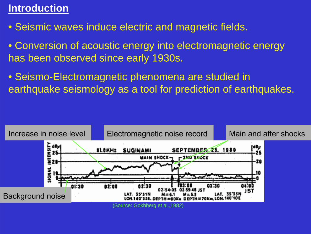
• Seismic waves induce electric and magnetic fields.
• Conversion of acoustic energy into electromagnetic energy has been observed since early 1930s.
• Seismo-Electromagnetic phenomena are studied in earthquake seismology as a tool for prediction of earthquakes.
Electromagnetic noise record Main and after shocks
Background noise
Increase in noise level
(Source: Gokhberg et al.,1982)
IntroductionMotivations for studying converted-wavefields
• Different properties of poro-elastic media influence the generation and propagation of electromagnetic waves than seismic waves.
• Consequently, we can extract more information about the reservoir and pore fluid from seismic and seismoelectric wave than seismic wave alone.
IntroductionMotivations for studying converted-wavefields
•Industry needs to directly detect fluids
•Seismoelectric and seismomagnetic (SeEM) effects are attached to fluid content
•SeEM waves are another converted wave –especially connected to P & S seismic waves
•Fertile research area, potential step-change for hydrocarbon exploration
Introduction
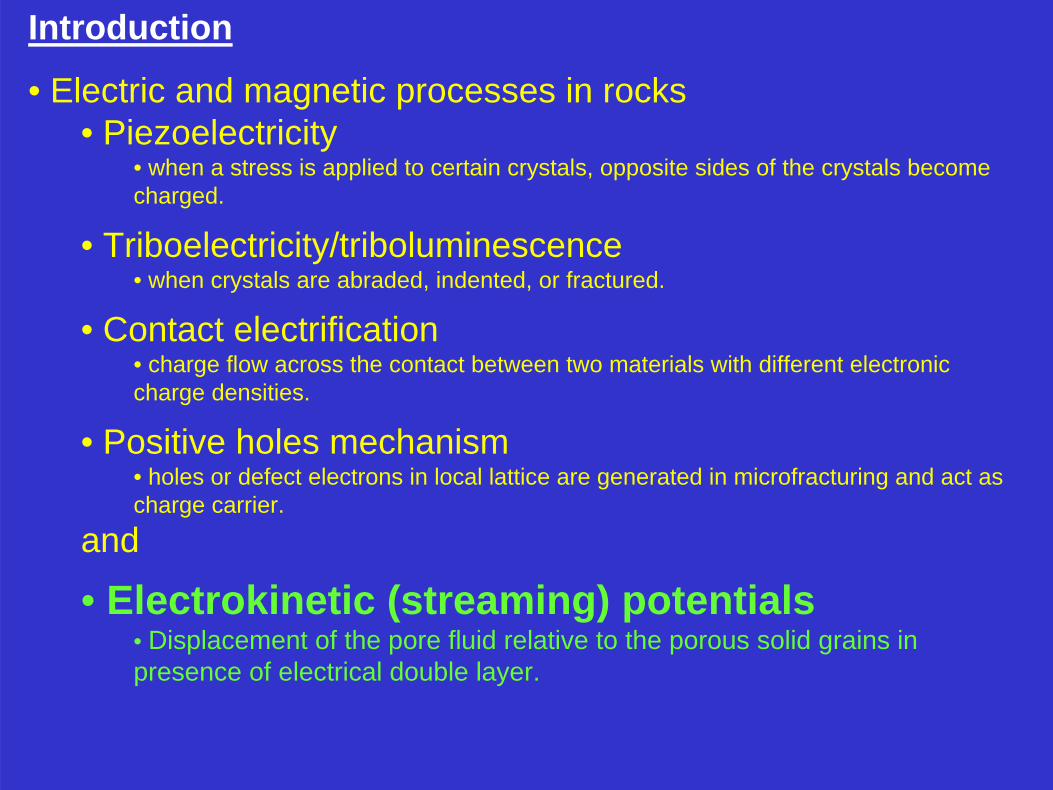
• Electric and magnetic processes in rocks • Piezoelectricity
• when a stress is applied to certain crystals, opposite sides of the crystals become charged.
• Triboelectricity/triboluminescence• when crystals are abraded, indented, or fractured.
• Contact electrification• charge flow across the contact between two materials with different electronic charge densities.
• Positive holes mechanism• holes or defect electrons in local lattice are generated in microfracturing and act as charge carrier.
and
• Electrokinetic (streaming) potentials• Displacement of the pore fluid relative to the porous solid grains in presence of electrical double layer.
Electrokinetic potentials
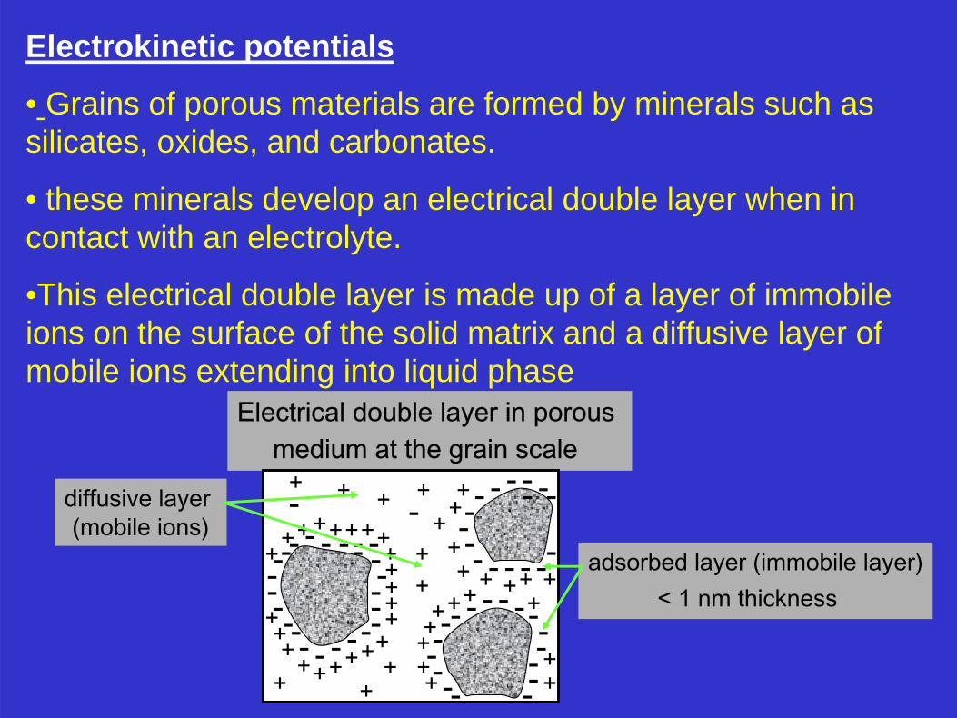
• Grains of porous materials are formed by minerals such as silicates, oxides, and carbonates.
• these minerals develop an electrical double layer when in contact with an electrolyte.
•This electrical double layer is made up of a layer of immobile ions on the surface of the solid matrix and a diffusive layer ofmobile ions extending into liquid phase
Electrical double layer in porous medium at the grain scale
adsorbed layer (immobile layer)< 1 nm thickness
- --- - - ---
--------- - - - --- - - - - ------- -
-----
---------- - - - ---++
+
++ + ++ +
+
++
++++
+
+++++++
+++++++++
++++++++
+ ++
++
++++--diffusive layer
(mobile ions)
Electrokinetic potentials
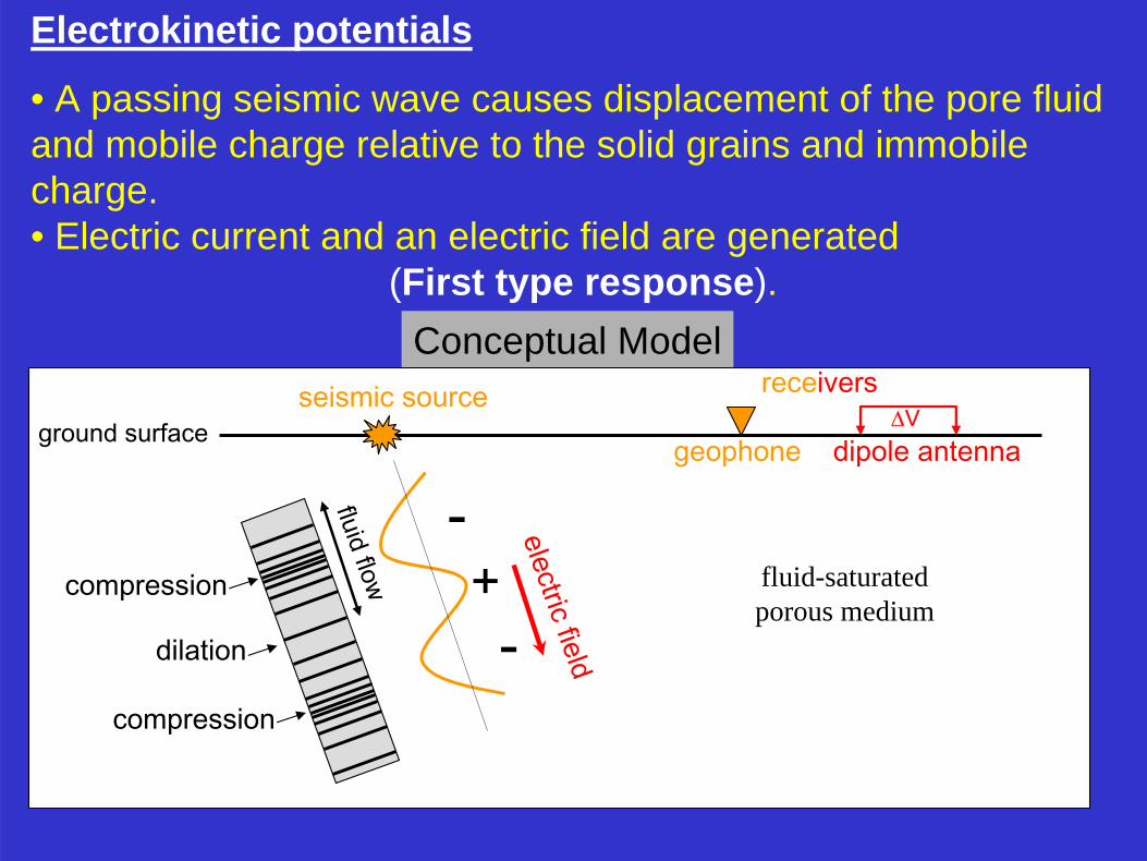
• A passing seismic wave causes displacement of the pore fluid and mobile charge relative to the solid grains and immobile charge.• Electric current and an electric field are generated
(First type response).Conceptual Model
fluid flow +-
compression
dilation
compression
-
seismic sourceground surface
electric field
receivers
geophone dipole antenna∆V
fluid-saturatedporous medium
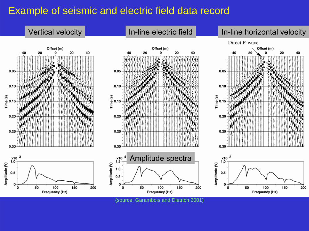
Example of seismic and electric field data record
Vertical velocity In-line electric field In-line horizontal velocity
Amplitude spectra
(source: Garambois and Dietrich 2001)
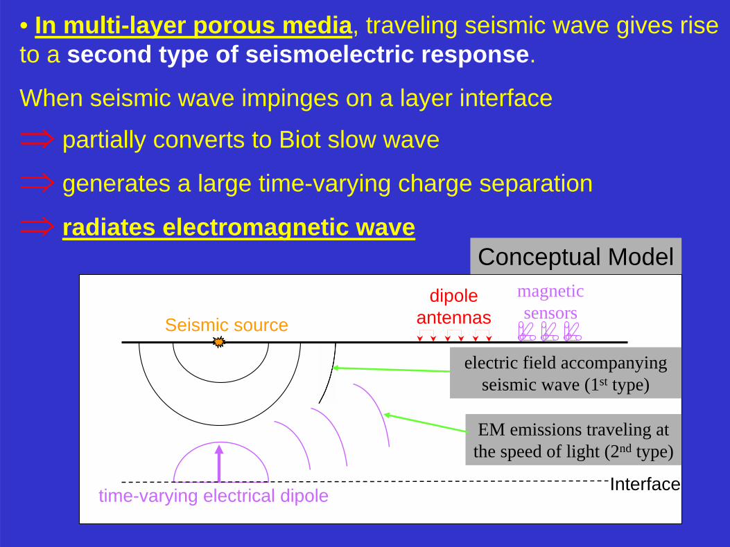
• In multi-layer porous media, traveling seismic wave gives rise to a second type of seismoelectric response.
When seismic wave impinges on a layer interface
⇒ partially converts to Biot slow wave
⇒ generates a large time-varying charge separation
⇒ radiates electromagnetic wave
Seismic source
time-varying electrical dipole
electric field accompanying seismic wave (1st type)
EM emissions traveling at the speed of light (2nd type)
dipole antennas
magnetic sensors
Interface
Conceptual Model

Seismic source
Interface
dipole antennas
dipole antennas
electric field
electric dipoles
first Fresnel zone
(source: Garambois and Dietrich 2001)
(source: Haines et. al. 2002)
field data
Synthetic data
Polarity reversal
Electromagnetic emission
generated at layer interface1st type response
2nd type response
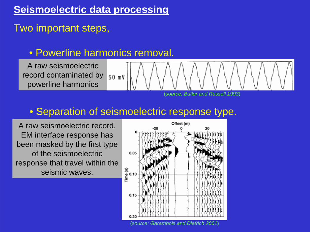
Seismoelectric data processing
Two important steps,
• Powerline harmonics removal.
• Separation of seismoelectric response type.
A raw seismoelectric record contaminated by
powerline harmonics(source: Butler and Russell 1993)
A raw seismoelectric record. EM interface response has
been masked by the first type of the seismoelectric
response that travel within the seismic waves.
(source: Garambois and Dietrich 2001)
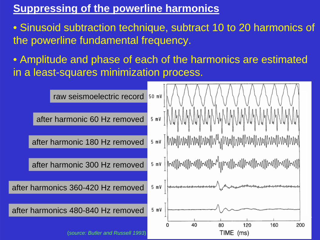
Suppressing of the powerline harmonics
• Sinusoid subtraction technique, subtract 10 to 20 harmonics of the powerline fundamental frequency.
• Amplitude and phase of each of the harmonics are estimated in a least-squares minimization process.
raw seismoelectric record
after harmonic 60 Hz removed
after harmonic 180 Hz removed
after harmonic 300 Hz removed
after harmonics 360-420 Hz removed
after harmonics 480-840 Hz removed
(source: Butler and Russell 1993)
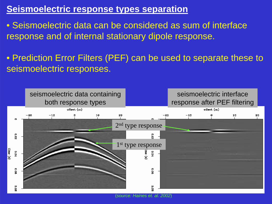
Seismoelectric response types separation
• Seismoelectric data can be considered as sum of interface response and of internal stationary dipole response.
• Prediction Error Filters (PEF) can be used to separate these toseismoelectric responses.
(source: Haines et. al. 2002)
seismoelectric data containing both response types
seismoelectric interface response after PEF filtering
1st type response
2nd type response
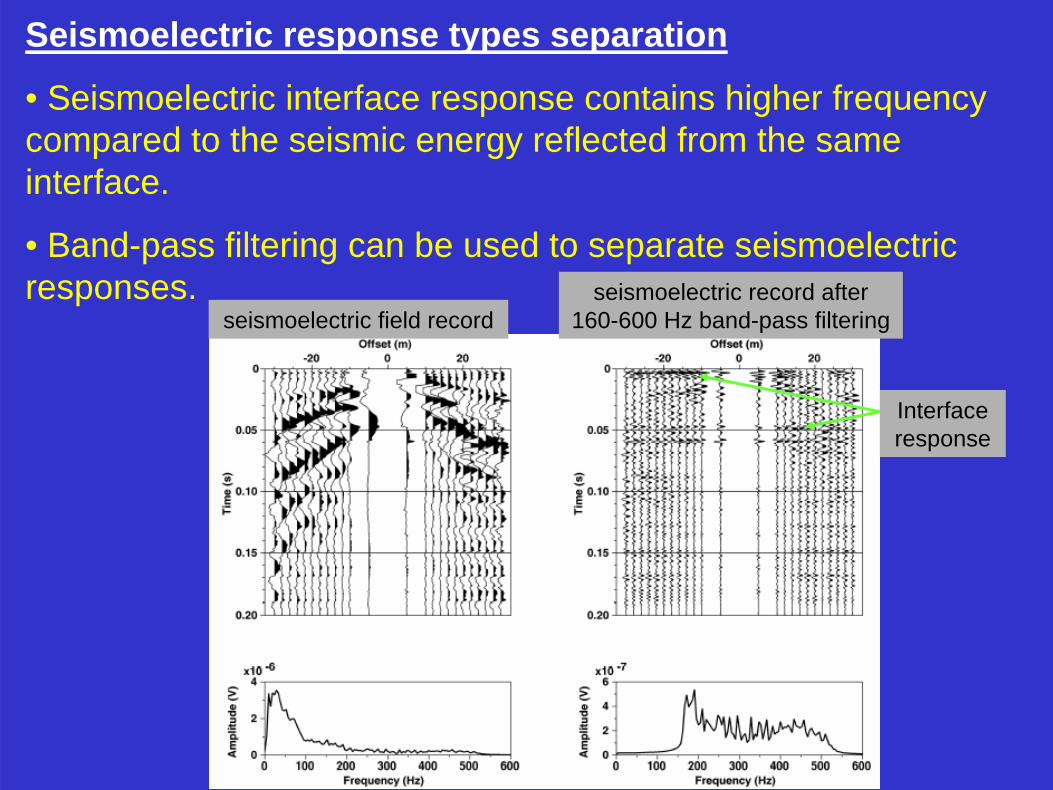
Seismoelectric response types separation
• Seismoelectric interface response contains higher frequency compared to the seismic energy reflected from the same interface.
• Band-pass filtering can be used to separate seismoelectric responses.
seismoelectric field recordseismoelectric record after
160-600 Hz band-pass filtering
Interface response
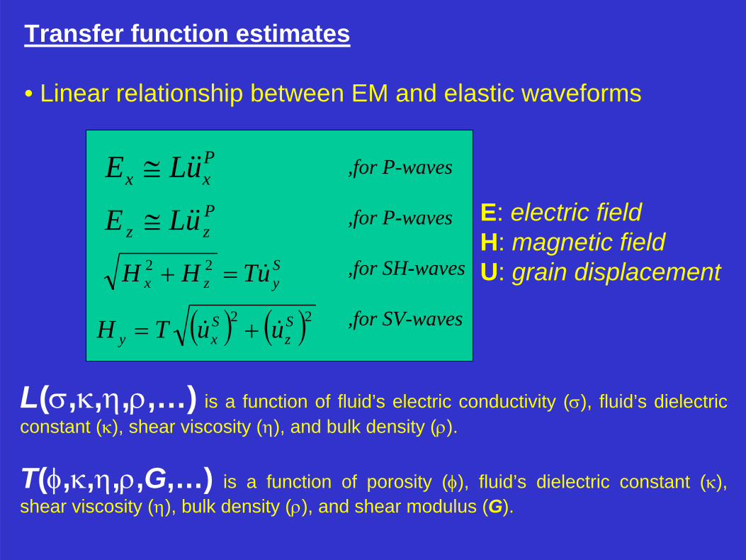
Transfer function estimates
• Linear relationship between EM and elastic waveforms
Pxx uLE ≅Pzz uLE ≅
Syzx uTHH =+ 22
( ) ( )22 Sz
Sxy uuTH +=
,for P-waves
,for SH-waves
,for P-waves
,for SV-waves
E: electric fieldH: magnetic fieldU: grain displacement
L(σ,κ,η,ρ,…) is a function of fluid’s electric conductivity (σ), fluid’s dielectric constant (κ), shear viscosity (η), and bulk density (ρ).
T(φ,κ,η,ρ,G,…) is a function of porosity (φ), fluid’s dielectric constant (κ), shear viscosity (η), bulk density (ρ), and shear modulus (G).
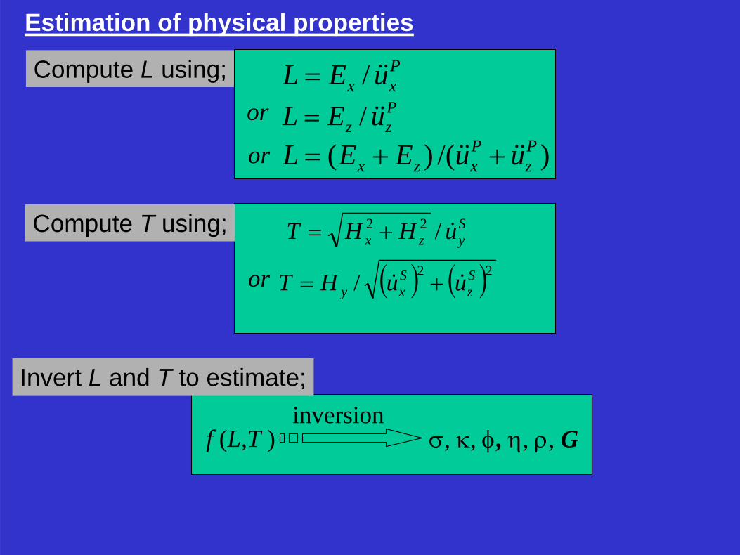
Estimation of physical properties
Compute L using; Pxx uEL /=Pzz uEL /=
Syzx uHHT /22 +=
( ) ( )22/ Sz
Sxy uuHT +=
)/()( Pz
Pxzx uuEEL ++=
or
or
Compute T using;
or
Invert L and T to estimate;
f (L,T ) σ, κ, φ, η, ρ, Ginversion
xy
z
Hx
HyHz
Uy
Ux
Uz3-C magnetic
sensor
Ex
EyEz
3-C electricsensor
3-C geophoneshotpoint
line of dipoles
line of shotpoints
line of geophones
line offset
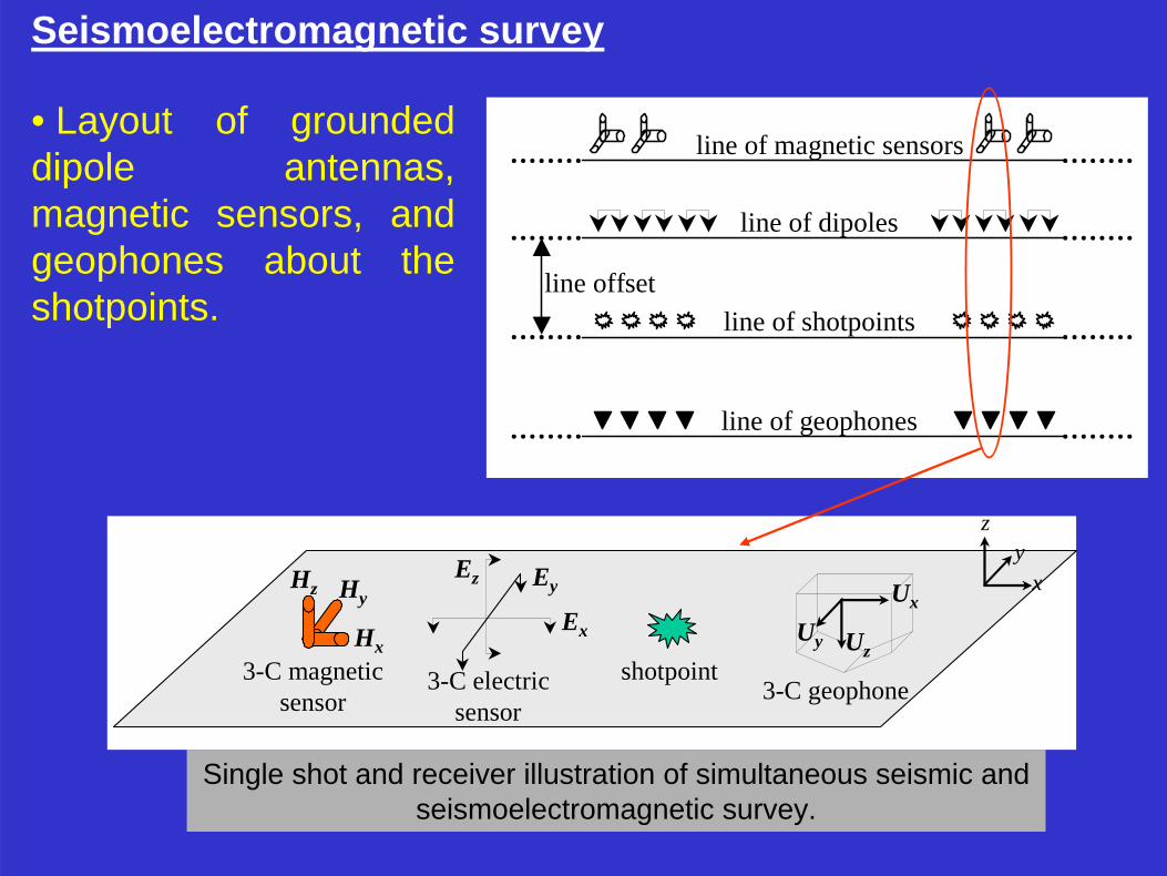
line of magnetic sensors• Layout of grounded dipole antennas, magnetic sensors, and geophones about the shotpoints.
Single shot and receiver illustration of simultaneous seismic and seismoelectromagnetic survey.
Seismoelectromagnetic survey
Summary• In multi-layer fluid-saturated media, two types of seismoelectric responses are generated:
• Internal stationary dipole response• Interface EM emission response
• Primary seismoelectric data processing includes:• Removal of powerline harmonic interferences• Response types separation
• Transfer functions between EM fields and elastic waves can be estimated by simultaneous measurements of multi-component electric and magnetic fields and seismic waves.
• Transfer functions composed of physical properties of formation’s pore-fluid and solid matrix: dielectric constant, electrical conductivity, porosity, shear viscosity, bulk density and, salt concentration
Acknowledgements
This research project has been funded by Alberta Energy Research Institute (AERI) under the COURSE program (Core University Research in Sustainable Energy) in 2004 for a 3-year period.
CREWES group is also thanked for their in-kind contributions and technical supports.
a

Strategy and the road ahead• Currently building team;
• Geophysics (Dr. R. Stewart, Dr. L. Bentley, Dr. M. Gharibi)
• Mechanical Engineering (Dr. A. Budiman)• AERI funding
• Connecting with established groups (e.g., Butler, UNB)
• Theory, numerical modeling then oilfield trial