Country Bridge Solutions · 2017-11-09 · Driven pile Precast reinforced concrete pile, installed...
22
Country Bridge Solutions Operation and maintenance guide Edition 2, Version 1.0 Roads and Maritime Services | September 2016
Transcript of Country Bridge Solutions · 2017-11-09 · Driven pile Precast reinforced concrete pile, installed...
Country Bridge Solutions Operation and maintenance guide Edition 2, Version 1.0
Roads and Maritime Services | September 2016

THIS PAGE LEFT INTENTIONALLY BLANK
Acknowledgements • Transport for New South Wales (TfNSW)
• Roads and Maritime Services
• Institute of Public Works Engineering Australia (IPWEA) NSW
The Institute of Public Works Engineering Australia (NSW Division) Roads and Transport Directorate has published the BRIDGEguide Bridge Inspection and Management Manual. This manual has been prepared to assist councils with the management of timber bridges, however the methods discussed can also be applied to any bridge type. The manual is an excellent reference document on how to manage an inventory of bridges by developing a bridge inspection and management system suited to Council’s needs.
Published by: Roads and Maritime Services
Phone: (02) 6640 1300 Monday to Friday between 8.30am and 4.30pm
Email: [email protected]
Website: www.rms.nsw.gov.au/business-industry/partners-suppliers/lgr/country-bridge-solutions.html
September 2016
RMS 16.501
ISBN 978-1-925582-15-4
i | Country Bridge Solutions – Operation and Maintenance guide i

Contents: 1 Common terms used in this guide ......................................................................................... 1
2 Introduction ............................................................................................................................. 3
2.1 This Guide ........................................................................................................................ 5
2.3 How to use this guide........................................................................................................ 7
3 Asset management process ................................................................................................... 7
3.1 Bridge inspections ............................................................................................................ 8
3.2 Bridge maintenance ........................................................................................................ 11
4 CBS operation and maintenance strategy ........................................................................... 12
4.1 Inspection and maintenance matrix................................................................................. 12
4.2 Maintenance items and methodology .............................................................................. 15
4.3 Demolition ....................................................................................................................... 15
5 Safety in design ..................................................................................................................... 16
6 References ............................................................................................................................. 17
6.1 Country Bridge Solutions materials ................................................................................. 17
ii | Country Bridge Solutions – Operation and Maintenance guide ii

1 Common terms used in this guide
Term Definition
Abutment sill beam Horizontal precast concrete member that supports the deck modules and retains earth fill at the abutments
Abutment wall panel Precast concrete that forms the abutment wall
Asset An item of economic value owned by a person or organisation
Asset Owner The person or body responsible for ownership of the bridge. The person or body responsible for procuring and managing the design and construction of the new bridge
Bridge inspection Periodic examination of the structural members of the bridge
CBS Country Bridge Solutions
Component Individual elements that combine to form the bridge asset
Contractor Organisation or individual that has been contracted to construct the bridge
Deck module CBS prestressed concrete double-T superstructure element
Designer Organisation/person responsible for the design and certification of the bridge
Design life The design life is the period from construction to when the asset remains suitable for service without requiring major maintenance
Driven pile Precast reinforced concrete pile, installed by driving
Health Safety in design (HSiD) Process to incorporate control measures at an early stage in the design process to eliminate risks, to manage risk, or to minimise the risks to as low as reasonably practicable for the life of the structure
Insitu (Latin) translates literally to "on site" or "in position", i.e. cast insitu concrete piers
Insitu concrete closure strip Permanent cast insitu concrete element that joins adjacent deck modules in the same span
Laminated elastomeric bearing
A bearing made from natural rubber that has two or more metal plates bonded into it
Low performance traffic barrier
Twin rail steel traffic barrier designed to meet low performance level criteria in accordance with AS5100
Maintenance The process used to preserve the current state
1 | Country Bridge Solutions – Operation and Maintenance guide 1

Term Definition
Maintenance free The asset or component requiring no major maintenance during its design life
Module holding down bracket Steel bracket system that provides uplift restraint between the deck modules and the abutment sill beam and/or pier headstock, particularly during flooding
Pier headstock Horizontal precast concrete member that supports the deck modules at piers
Road maintenance inspection Periodic inspection of the road surfacing, drainage, signage and traffic barriers
Roads and Maritime Services Engineering Services – Bridge Engineering
The authority responsible for design and certification of CBS components
Safe work method statement (SWMS)
Document used for managing risk in delivering work. Identifies the activities, the risks and the mitigation measures
Scour protection Measures taken to reduce the effects of scour around bridge foundations and road embankments, such as large loose stones (rip rap) or gabions
Scuppers Deck surface drainage pipe
Shear key plinth Structural component to ensure transfer of shearing forces between bridge superstructure and substructure
Soffit Downward facing surface of any bridge component
Thrie beam A longitudinal semi-rigid steel barrier comprising post and rail
2 | Country Bridge Solutions – Operation and Maintenance guide 2
2 Introduction
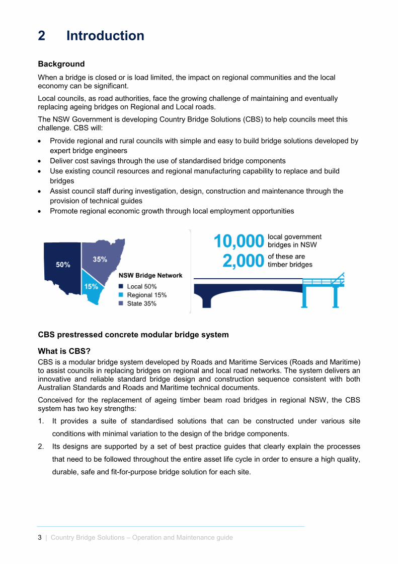
Background When a bridge is closed or is load limited, the impact on regional communities and the local economy can be significant.
Local councils, as road authorities, face the growing challenge of maintaining and eventually replacing ageing bridges on Regional and Local roads.
The NSW Government is developing Country Bridge Solutions (CBS) to help councils meet this challenge. CBS will:
• Provide regional and rural councils with simple and easy to build bridge solutions developed by expert bridge engineers
• Deliver cost savings through the use of standardised bridge components • Use existing council resources and regional manufacturing capability to replace and build
bridges • Assist council staff during investigation, design, construction and maintenance through the
provision of technical guides • Promote regional economic growth through local employment opportunities
CBS prestressed concrete modular bridge system
What is CBS? CBS is a modular bridge system developed by Roads and Maritime Services (Roads and Maritime) to assist councils in replacing bridges on regional and local road networks. The system delivers an innovative and reliable standard bridge design and construction sequence consistent with both Australian Standards and Roads and Maritime technical documents.
Conceived for the replacement of ageing timber beam road bridges in regional NSW, the CBS system has two key strengths:
1. It provides a suite of standardised solutions that can be constructed under various site
conditions with minimal variation to the design of the bridge components.
2. Its designs are supported by a set of best practice guides that clearly explain the processes
that need to be followed throughout the entire asset life cycle in order to ensure a high quality,
durable, safe and fit-for-purpose bridge solution for each site.
3 | Country Bridge Solutions – Operation and Maintenance guide 3
Key features of CBS include:
• A suite of standard bridge drawings for a modular bridge solution. • Guidance on solution selection, site investigation, detailed design, construction, operation and
maintenance management provided in a set of four best practice guides. • A fully certified bridge deck system, incorporating prestressed concrete double-T deck
modules. • Standardised substructure components that can be easily adapted to suit a range of site
conditions. • Three standard bridge configurations to suit different future traffic demands and site
constraints, including a two-lane and a single-lane ‘stitched’ solution, as well as a simplified ‘butted’ solution for remote sites with very low expected heavy vehicle traffic volumes.
Why CBS? The CBS system provides councils with:
1. High quality, durable and easy to build structural solutions developed by technical experts in
bridge infrastructure and explained in guides written in plain language.
2. New bridges designed to current Australian bridge design standard traffic loading.
3. Opportunity to improve access for heavy vehicles and agricultural equipment through an
enhanced standard carriageway width.
4. Opportunities to use local labour resources and regional manufacturing capability.
5. Transportability of precast components on standard General Access trucks.
6. Minimised on-site concrete requirements, especially for remote lightly trafficked sites.
7. Low performance level traffic barriers suitable for submergence.
8. Guidance on bridge asset management.
9. Reduced maintenance requirements resulting from a 100 year design life.
10. Increased capacity of regional transport networks to the benefit of community and commerce.
Responsibilities Roads and Maritime has standard drawings for the components of a modular bridge solution, as well as guides covering solution selection, site investigation, detailed design, construction, operation and maintenance management.
Though not an exhaustive list, the responsibilities of the council, should they choose to use CBS, include the following:
• Produce or procure a set of detailed drawings for each site, incorporating the standard deck modular system and adapting the substructure components to the site conditions
• Certify the final bridge design for the site • Meet all WHS obligations during investigation, design, construction and maintenance
operations • Meet all environment and heritage obligations during investigation, design, construction and
maintenance operations.
4 | Country Bridge Solutions – Operation and Maintenance guide 4

2.1 This Guide This guide is intended to assist those who are familiar with asset management to operate and maintain Country Bridge Solutions (CBS) bridges. It provides advice specific to the CBS bridges for the different stages of operation and maintenance, from bridge inspections through to bridge removal. Guidance has been provided based on Roads and Maritime Services (Roads and Maritime) standard practice and polices. The Council may choose to use its own policies and procedures.
As every bridge replacement project is unique, this guide provides general information only. However, progressing through the various operation and maintenance stages in the methodical manner described will help to ensure that the bridge operational requirements are met.
This guide is intended to assist Council to make informed decisions. It promotes operation and maintenance practices recommended by experienced bridge engineers.
The diagram below shows how this guide sits within the overall structure of the CBS process.
Figure 2-1: The CBS process
2.2. Country Bridge Solutions delivery process The following information provides a brief outline of the CBS delivery process to assist the reader during the suitability and investigation phase.
The CBS system delivers a set of standard components that can be combined and used for specific bridge sites with a minimum amount of design work required to complete a drawing set for a new bridge.
The whole CBS delivery process, and how the four guides combine with the CBS standard drawings and council requirements to inform that process, is shown below.
Suitability and Investigation Design Construction
Operation and
Maintenance
5 | Country Bridge Solutions – Operation and Maintenance guide 5

CBS Suitability
Investigation
Bridge Design
CBS Standard Drawings
Council Requirements
Construction
Operation and Maintenance
CBS Design Guide
CBS Construction Guide
CBS Operations and Maintenance Guide
CBS Suitability and Investigation Guide
Country Bridge Solutions delivery process
6 | Country Bridge Solutions – Operation and Maintenance guide 6
2.3 How to use this guide The intent of this guide is to guide the reader through each of the stages in operating and maintaining the bridge. The information is presented as three distinct sets of activities:
• Process of operation and maintenance
• Strategy of inspections and maintenance
• Methodology for the inspections and maintenance.
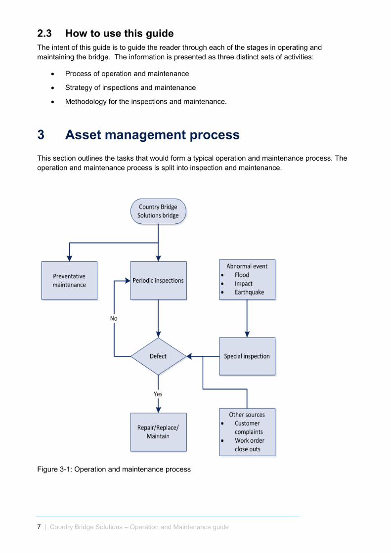
3 Asset management process This section outlines the tasks that would form a typical operation and maintenance process. The operation and maintenance process is split into inspection and maintenance.
Figure 3-1: Operation and maintenance process
7 | Country Bridge Solutions – Operation and Maintenance guide 7
3.1 Bridge inspections The following section outlines the basic procedures that would be employed to inspect bridge structures and provides additional information on establishing a typical inspection process.
3.1.1 Objectives of inspections The general objectives of inspections include:
• To check the general serviceability of the structure for obvious signs of defects which might affect the immediate safety of road users
• To identify maintenance items that require immediate action and/or to schedule routine maintenance for completion at a later date.
• Identify and prioritise maintenance needs including monitoring, maintenance and/or repair or further investigation
• Assess the effectiveness of past maintenance treatments
• Model and forecast changes in condition (deterioration modelling) and residual life
• Estimate future requirements for maintenance budgets.
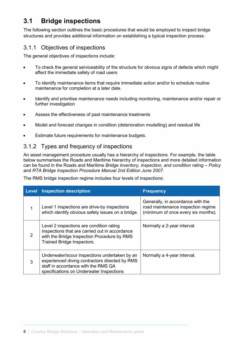
3.1.2 Types and frequency of inspections An asset management procedure usually has a hierarchy of inspections. For example, the table below summarises the Roads and Maritime hierarchy of inspections and more detailed information can be found in the Roads and Maritime Bridge inventory, inspection, and condition rating – Policy and RTA Bridge Inspection Procedure Manual 2nd Edition June 2007.
The RMS bridge inspection regime includes four levels of inspections:
Level Inspection description Frequency
1 Level 1 inspections are drive-by inspections which identify obvious safety issues on a bridge.
Generally, in accordance with the road maintenance inspection regime (minimum of once every six months).
2
Level 2 inspections are condition rating inspections that are carried out in accordance with the Bridge Inspection Procedure by RMS Trained Bridge Inspectors.
Normally a 2-year interval.
3 Underwater/scour inspections undertaken by an experienced diving contractors directed by RMS staff in accordance with the RMS QA specifications on Underwater Inspections
Normally a 4-year interval.
8 | Country Bridge Solutions – Operation and Maintenance guide 8
Level Inspection description Frequency
4 Level 3 inspections are structural engineering inspections carried out by an experienced structural engineer with a RMS Trained Bridge Inspector.
The need for a Level 3 inspection is identified by:
I. A level 2 inspection, II. A Level 4 inspection
indicating strength issues, or III. Performance of similar class
of bridges/ bridge elements. IV. Incident on the bridge
impacting structural capacity V. Post natural disaster such as
heavy floods, earth quake etc.
5
Level 4 inspections involve load assessment due to proposed changes in legal loading, new vehicle types, or the need to confirm the structural capacity of a bridge carried out by an experienced structural engineer.
As requested for changes in legal loads or new vehicles.
Table 3-1 – Sample of hierarchy of inspections
Note: RMS Level 2 inspections are based on a visual assessment process, and the only requirement is that the RMS Trained Bridge Inspector can observe the bridge elements sufficiently, to enable a reliable assessment to be made against set condition state criteria. Where observations are obscured by debris, staining, and corrosion products, etc., these materials must be removed prior to making condition assessments.
3.1.3 Safety Inspections shall be completed in accordance with the Work Health and Safety Act 2011 and the Work Health and Safety Regulation 2011.
3.1.4 Scope of CBS bridge inspections For the CBS system and this guide, the focus is on Level 1 and 2 inspections. If a Level 3 or 4 inspection is required, then CBS recommends council contact an experienced structural engineer.
Level 1 inspection shall include all visible structural components including, approaches and waterways at bridges and major culverts. The inspector shall assess and report any significant signs of deterioration, damage, distress or unusual behaviour due to vehicle impact, flood or fire damage. The report may include recommendations for further investigation (e.g. Level 3). The report should include photographs of items that require further assessment or maintenance.
The scope of the Level 2 inspection includes the following:
• Visual inspection of components to assess their condition using a condition rating system
• Reporting the condition and its extent for each bridge component
• A condition rating for the overall structure (Bridge Condition Rating)
• Identification of structures and/or components which may require a detailed structural engineering inspection (Level 3) due to rapid changes in structural condition or deterioration to condition rating 4
9 | Country Bridge Solutions – Operation and Maintenance guide 9
• Identification of components which require closer condition monitoring and observation at the next inspection due to rapid changes in structural condition or deterioration to condition rating 3
• Identification of supplementary testing
• A photographic record of the structure
• Auditing of selected components for structure inventory records.
The inspections will require access platforms. As the access platforms will typically be hired, it is prudent to schedule inspection and maintenance tasks together. The general requirements of inspections should include:
• Planned access to enable safe inspections (provision of access platforms if required)
• Utilisation of experienced personnel
• Safe work methodologies
• Use consistent inspection methodologies and terminologies
• Prepare detailed inspection records
• Review past inspection records prior to the inspection
• On site use of past inspection records.
3.1.5 Inspection records Detailed inspection records must be maintained for all inspections. These records should be used as the basis for both maintenance works and future inspections. The records should include as a minimum:
• Provide meticulous and detailed observations using qualitative information
• Describe the components
• Described the type, extent and quantity or observed defects
• Rate the defects
• Supplement specific problem areas using photographs
• Use consistent forms, diagrams and terminologies
• Use consistent methods of inspection
• Items noted during maintenance or repairs tasks
• Maintenance and repair actions required and when it should be undertaken
• Format of the data recorded.
All inspections and outcomes should be recorded in the asset management system.
10 | Country Bridge Solutions – Operation and Maintenance guide 10

3.2 Bridge maintenance The primary objective of maintenance activities should be preventative in order to avoid the need for member replacement or other major repairs. Delivering this objective will be different for different authorities and the authority will need to balance operation expenditure against capital expenditure. Maintaining safe access for road users (including for emergency access) is the primary objective for bridge asset management.
3.2.1 General requirements The general requirements for routine maintenance include:
• Sourcing of experienced and qualified personnel
• Selection of durable materials and use of industry-accepted repair methods
• Required road user level of service
• Financial considerations
• Utilisation of consistent maintenance methods
• Preparation of detailed record of work performed
• On site use of inspection records
• Supervision and verification of the repair work by experienced personnel.
3.2.2 Types of maintenance tasks Maintenance tasks are split into routine maintenance procedures (clearing deck drainage scuppers) and repair or replacement of items as identified in the inspection process:
• Routine maintenance are the periodic tasks that are required to keep the asset/component in a satisfactory condition, including cleaning deck drainage scuppers.
• Repair or replacement to the asset/component when the condition has reached an unsatisfactory level, including replacing elastomeric bearings, and replacing deck seals.
11 | Country Bridge Solutions – Operation and Maintenance guide 11
4 CBS operation and maintenance strategy
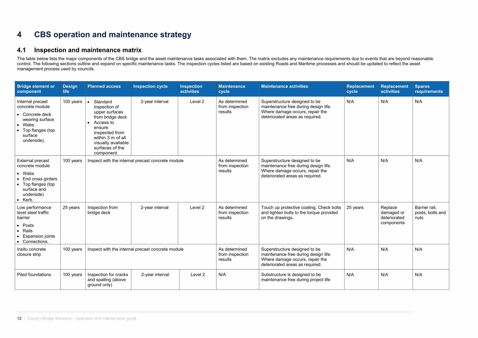
4.1 Inspection and maintenance matrix The table below lists the major components of the CBS bridge and the asset maintenance tasks associated with them. The matrix excludes any maintenance requirements due to events that are beyond reasonable control. The following sections outline and expand on specific maintenance tasks. The inspection cycles listed are based on existing Roads and Maritime processes and should be updated to reflect the asset management process used by councils:
Bridge element or component
Design life
Planned access Inspection cycle Inspection activities
Maintenance cycle
Maintenance activities Replacement cycle
Replacement activities
Spares requirements
Internal precast concrete module
• Concrete deck wearing surface
• Webs • Top flanges (top
surface underside).
100 years • Standard inspection of upper surfaces from bridge deck
• Access to ensure inspected from within 3 m of all visually available surfaces of the component.
2-year interval Level 2 As determined from inspection results
Superstructure designed to be maintenance free during design life. Where damage occurs, repair the deteriorated areas as required.
N/A N/A N/A
External precast concrete module
• Webs • End cross girders • Top flanges (top
surface and underside)
• Kerb.
100 years Inspect with the internal precast concrete module As determined from inspection results
Superstructure designed to be maintenance free during design life. Where damage occurs, repair the deteriorated areas as required.
N/A N/A N/A
Low performance level steel traffic barrier
• Posts • Rails • Expansion joints • Connections.
25 years Inspection from bridge deck
2-year interval Level 2 As determined from inspection results
Touch up protective coating. Check bolts and tighten bolts to the torque provided on the drawings.
25 years Replace damaged or deteriorated components
Barrier rail, posts, bolts and nuts
Insitu concrete closure strip
100 years Inspect with the internal precast concrete module As determined from inspection results
Superstructure designed to be maintenance free during design life. Where damage occurs, repair the deteriorated areas as required.
N/A N/A N/A
Piled foundations 100 years Inspection for cracks and spalling (above ground only)
2-year interval Level 2 N/A Substructure is designed to be maintenance free during project life
N/A N/A N/A
12 | Country Bridge Solutions – Operation and maintenance guide Edition 2 Version 1 UNCONTROLLED WHEN PRINTED 12

Bridge element or component
Design life
Planned access Inspection cycle Inspection activities
Maintenance cycle
Maintenance activities Replacement cycle
Replacement activities
Spares requirements
Precast reinforced concrete abutment sill beam and wall panel
• Lateral restraint blocks
• Curtain wall • Wing wall returns • Kerb.
100 years Access to ensure inspected from within 3 m of all visually available surfaces of the component.
2-year interval Level 2 As determined from inspection results
Substructure is designed to be maintenance free during project life. Where damage occurs, repair the deteriorated areas as required.
N/A N/A N/A
Precast reinforced concrete pier headstock
• Lateral restraint blocks
100 years Access to ensure inspected from within 3 m of all visually available surfaces of the component.
2-year interval Substructure is designed to be maintenance free during project life. Where damage occurs, repair the deteriorated areas as required.
N/A N/A N/A N/A N/A
Laminated elastomeric bearing
100 years Access to ensure inspected from within 3 m of all visually available surfaces of the component.
2-year interval Level 2 As determined from inspection results
Remove debris from the bearings As required Jack up modules simultaneously and replace bearing
N/A
Shear key plinth 100 years Access to ensure inspected from within 3 m of all visually available surfaces of the component.
2-year interval and after significant flood
events
Level 2 As determined from inspection results
Shear key is designed to be maintenance free during project life. Where damage occurs, repair the deteriorated areas as required.
As required Replace damaged or deteriorated components
N/A
Module holding down bracket
40 years Access to ensure inspected from within 3 m of all visually available surfaces of the component.
2-year interval and after significant flood
events
Level 2 As determined from inspection results
• Touch up protective coating • Replacement of missing nuts • Tightening of bolts.
As required Replace damaged or deteriorated components
N/A
Sealant deck joint 25 years Inspection from bridge deck
2-year interval Level 2 As determined from inspection results
Remove debris from the joints 25 years Replace damaged or deteriorated components
N/A
Thrie beam
• Transition connection
25 years Inspection from bridge deck
2-year interval Level 2 As determined from inspection results
• Touch up protective coating • Check bolts and tighten bolts to the
torque provided on the drawings.
25 years Replace damaged or deteriorated components
N/A
13 | Country Bridge Solutions – Operation and maintenance guide Edition 2 Version 1 UNCONTROLLED WHEN PRINTED 13

Bridge element or component
Design life
Planned access Inspection cycle Inspection activities
Maintenance cycle
Maintenance activities Replacement cycle
Replacement activities
Spares requirements
Deck running surface / sprayed seal (if applicable)
10 years Inspection from bridge deck
Inspected as part of road maintenance inspection regime and 2-yearly bridge inspection
Level 1 and 2 As determined from inspection results Where damage occurs, repair the
deteriorated areas as required.
N/A N/A N/A
Scuppers 100 years Inspection from bridge deck
Inspected as part of road maintenance inspection regime and 2-yearly bridge inspection
Level 1 and 2 Annually Remove debris from the scuppers 25 years Replace damaged or missing pipes
N/A
Table 4-1 – Sample of hierarchy of inspections
14 | Country Bridge Solutions – Operation and maintenance guide Edition 2 Version 1 UNCONTROLLED WHEN PRINTED 14

4.2 Maintenance items and methodology The following section outlines the methodology used for the inspection and maintenance of items associated with the bridge.
4.2.1 Bearings The lifting operation and bearing replacement shall be carried out when the bridge is closed. No traffic is to be on the bridge during bearing replacement. The jacks shall be located underneath the end cross girders, in the position shown on the drawings.
The replacement of bearings can be carried out using lock nut jacks which are hydraulically linked at one location with a control mechanism. Dial gauges and load cells will need to be installed to measure and monitor the amount of lift to ensure the same vertical displacements are achieved at each jacking point at all times during the jacking operations.
Access to the bearings for replacement can be provided by using mobile plant such as cherry picker or scissor lift or by constructing temporary scaffolding positioned in front of the respective abutment and piers.
4.3 Demolition Demolition of the CBS structure should be undertaken by a WorkSafe NSW licensed demolition contractor using appropriately qualified personnel. At the end of its service life, an engineer and licensed demolition contractor should be engaged to prepare a demolition plan.
The intended demolition sequence is typically a reversal of the construction sequence, to be determined in accordance with current WHS Legislation and requirements such as the Demolition Work Code of Practice 2015. The presence of any hazardous may require additional controls, licensing and qualification.
15 | Country Bridge Solutions – Operation and maintenance guide 15
5 Safety in design Safety in design (SID) considers the risks associated with choices made in design and construction of the bridge and how design changes can be made to remove (eliminate) or reduce (minimise) their effects. The standard design assumes the asset owner, designer and contractor are familiar and aware of the risks associated with structural work. The work will require a site specific risk assessment process.
To comply with the NSW Work Health and Safety Act and Regulation 2011 and the Safe design of structures Code of Practice, SID is a key process required when designing the new bridge. The aim of SID is to ensure, so far as is reasonably practicable, that the designed structure poses no risks to the health and safety of people who construct, use, maintain or demolish them.
The process is carried out at the beginning of the design and at key stages throughout the development of the design. SID reviews are usually carried out using the Construction Hazard Assessment Implication Review (CHAIR) process and consider all hazards relating to construction, commissioning, operation, maintenance and decommissioning of the work. The intention is to ensure that hazards relating to design are identified at an early stage and that systems are established to control these issues and hazards.
16 | Country Bridge Solutions – Operation and maintenance guide 16

6 References The following publications are referenced in this guide:
• IPWEA (NSW) (2009) BRIDGEguide Bridge Inspection and Management Manual.
• Roads and Maritime Services (2011) Bridge inventory, inspection and condition rating - Policy
• NSW Work Health and Safety Act and Regulation 2011 and the Safe design of structures Code of Practice
6.1 Country Bridge Solutions materials • Country Bridge Solutions overarching guide
• Country Bridge Solutions suitability and investigation guide
• Country Bridge Solutions design guide
• Country Bridge Solutions construction guide.
• Country Bridge Solutions operation and maintenance guide
17 | Country Bridge Solutions – Operation and maintenance guide 17

rms.nsw.gov.au/countrybridgesolutions
13 22 13
Customer feedback Roads and Maritime Locked Bag 928, North Sydney NSW 2059
September 2016 RMS 16.501
ISBN: 978-1-925582-15-4


![[PPT]PowerPoint Presentation - National Precast Concrete …precast.org/wp-content/uploads/2017/03/Cranes-and... · Web viewWhat Equipment is Covered? Dedicated pile drivers Service/mechanic](https://static.fdocuments.net/doc/165x107/5af7d12a7f8b9aac248c4b90/pptpowerpoint-presentation-national-precast-concrete-viewwhat-equipment.jpg)