Counters - Northern India Engineering College · Counters XST is able to ... 4-bit Unsigned Up...
19
Counters XST is able to recognize counters with the following controls signals: Asynchronous Set/Clear Synchronous Set/Clear Asynchronous/Synchronous Load (signal and/or constant) Clock Enable Modes (Up, Down, Up/Down) Mixture of all mentioned above possibilities HDL coding styles for the following control signals are equivalent to the ones described in the "Registers" section of this chapter: Clock Asynchronous Set/Clear Synchronous Set/Clear Clock Enable 4-bit Unsigned Up Counter with Asynchronous Clear The following table shows pin definitions for a 4-bit unsigned up counter with asynchronous clear. IO Pins Description C Positive-Edge Clock CLR Asynchronous Clear (active High) Q[3:0] Data Output VHDL Code Following is VHDL code for a 4-bit unsigned up counter with asynchronous clear. library ieee; use ieee.std_logic_1164.all; use ieee.std_logic_unsigned.all; entity counter is port(C, CLR : in std_logic; Q : out std_logic_vector(3 downto 0)); end counter; architecture archi of counter is signal tmp: std_logic_vector(3 downto 0); begin process (C, CLR) begin if (CLR='1') then tmp <= "0000"; elsif (C'event and C='1') then tmp <= tmp + 1; end if; end process; Q <= tmp; end archi; 4-bit Unsigned Down Counter with Synchronous Set The following table shows pin definitions for a 4-bit unsigned down counter with synchronous set. gggggg Description C Positive-Edge Clock S Synchronous Set (active High) Q[3:0] Data Output
Transcript of Counters - Northern India Engineering College · Counters XST is able to ... 4-bit Unsigned Up...

Counters
XST is able to recognize counters with the following controls signals:
Asynchronous Set/Clear
Synchronous Set/Clear
Asynchronous/Synchronous Load (signal and/or constant)
Clock Enable
Modes (Up, Down, Up/Down)
Mixture of all mentioned above possibilities
HDL coding styles for the following control signals are equivalent to the ones described in the
"Registers" section of this chapter:
Clock
Asynchronous Set/Clear
Synchronous Set/Clear
Clock Enable
4-bit Unsigned Up Counter with Asynchronous Clear The following table shows pin definitions for a 4-bit unsigned up counter with asynchronous
clear. IO Pins Description
C Positive-Edge Clock
CLR Asynchronous Clear (active High)
Q[3:0] Data Output
VHDL Code
Following is VHDL code for a 4-bit unsigned up counter with asynchronous clear. library ieee; use ieee.std_logic_1164.all;
use ieee.std_logic_unsigned.all;
entity counter is
port(C, CLR : in std_logic;
Q : out std_logic_vector(3 downto 0));
end counter;
architecture archi of counter is
signal tmp: std_logic_vector(3 downto 0);
begin
process (C, CLR)
begin
if (CLR='1') then
tmp <= "0000";
elsif (C'event and C='1') then
tmp <= tmp + 1;
end if;
end process;
Q <= tmp;
end archi;
4-bit Unsigned Down Counter with Synchronous Set The following table shows pin definitions for a 4-bit unsigned down counter with synchronous
set. gggggg Description
C Positive-Edge Clock
S Synchronous Set (active High)
Q[3:0] Data Output

VHDL Code
Following is the VHDL code for a 4-bit unsigned down counter with synchronous set. library ieee;
use ieee.std_logic_1164.all;
use ieee.std_logic_unsigned.all;
entity counter is
port(C, S : in std_logic;
Q : out std_logic_vector(3 downto 0));
end counter;
architecture archi of counter is
signal tmp: std_logic_vector(3 downto 0);
begin
process (C)
begin
if (C'event and C='1') then
if (S='1') then
tmp <= "1111";
else
tmp <= tmp - 1;
end if;
end if;
end process;
Q <= tmp;
end archi;
4-bit Unsigned Up Counter with Asynchronous Load from Primary Input The following table shows pin definitions for a 4-bit unsigned up counter with asynchronous
load from primary input. IO Pins Description
C Positive-Edge Clock
ALOAD Asynchronous Load (active High)
D[3:0] Data Input
Q[3:0] Data Output
VHDL Code
Following is the VHDL code for a 4-bit unsigned up counter with asynchronous load from
primary input. library ieee;
use ieee.std_logic_1164.all;
use ieee.std_logic_unsigned.all;
entity counter is
port(C, ALOAD : in std_logic;
D : in std_logic_vector(3 downto 0);
Q : out std_logic_vector(3 downto 0));
end counter;
architecture archi of counter is
signal tmp: std_logic_vector(3 downto 0);
begin
process (C, ALOAD, D)
begin
if (ALOAD='1') then
tmp <= D;
elsif (C'event and C='1') then
tmp <= tmp + 1;
end if;
end process;
Q <= tmp;

end archi;
4-bit Unsigned Up Counter with Synchronous Load with a Constant The following table shows pin definitions for a 4-bit unsigned up counter with synchronous load
with a constant.
IO Pins Description
C Positive-Edge Clock
SLOAD Synchronous Load (active High)
Q[3:0] Data Output
VHDL Code
Following is the VHDL code for a 4-bit unsigned up counter with synchronous load with a
constant. library ieee;
use ieee.std_logic_1164.all;
use ieee.std_logic_unsigned.all;
entity counter is
port(C, SLOAD : in std_logic;
Q : out std_logic_vector(3 downto 0));
end counter;
architecture archi of counter is
signal tmp: std_logic_vector(3 downto 0);
begin
process (C)
begin
if (C'event and C='1') then
if (SLOAD='1') then
tmp <= "1010";
else
tmp <= tmp + 1;
end if;
end if;
end process;
Q <= tmp;
end archi;
4-bit Unsigned Up Counter with Asynchronous Clear and Clock Enable The following table shows pin definitions for a 4-bit unsigned up counter with asynchronous
clear and clock enable. IO Pins Description
C Positive-Edge Clock
CLR Asynchronous Clear (active High)
CE Clock Enable
Q[3:0] Data Output
VHDL Code
Following is the VHDL code for a 4-bit unsigned up counter with asynchronous clear and clock
enable. library ieee;
use ieee.std_logic_1164.all;
use ieee.std_logic_unsigned.all;
entity counter is
port(C, CLR, CE : in std_logic;
Q : out std_logic_vector(3 downto 0));

end counter;
architecture archi of counter is
signal tmp: std_logic_vector(3 downto 0);
begin
process (C, CLR)
begin
if (CLR='1') then
tmp <= "0000";
elsif (C'event and C='1') then
if (CE='1') then
tmp <= tmp + 1;
end if;
end if;
end process;
Q <= tmp;
end archi;
4-bit Unsigned Up/Down counter with Asynchronous Clear The following table shows pin definitions for a 4-bit unsigned up/down counter with
asynchronous clear. IO Pins Description
C Positive-Edge Clock
CLR Asynchronous Clear (active High)
UP_DOWN up/down count mode selector
Q[3:0] Data Output
VHDL Code
Following is the VHDL code for a 4-bit unsigned up/down counter with asynchronous clear. library ieee;
use ieee.std_logic_1164.all;
use ieee.std_logic_unsigned.all;
entity counter is
port(C, CLR, UP_DOWN : in std_logic;
Q : out std_logic_vector(3 downto 0));
end counter;
architecture archi of counter is
signal tmp: std_logic_vector(3 downto 0);
begin
process (C, CLR)
begin
if (CLR='1') then
tmp <= "0000";
elsif (C'event and C='1') then
if (UP_DOWN='1') then
tmp <= tmp + 1;
else
tmp <= tmp - 1;
end if;
end if;
end process;
Q <= tmp;
end archi;
4-bit Signed Up Counter with Asynchronous Reset The following table shows pin definitions for a 4-bit signed up counter with asynchronous reset. IO Pins Description
C Positive-Edge Clock
CLR Asynchronous Clear (active High)
Q[3:0] Data Output
VHDL Code

Following is the VHDL code for a 4-bit signed up counter with asynchronous reset. library ieee;
use ieee.std_logic_1164.all;
use ieee.std_logic_signed.all;
entity counter is
port(C, CLR : in std_logic;
Q : out std_logic_vector(3 downto 0));
end counter;
architecture archi of counter is
signal tmp: std_logic_vector(3 downto 0);
begin
process (C, CLR)
begin
if (CLR='1') then
tmp <= "0000";
elsif (C'event and C='1') then
tmp <= tmp + 1;
end if;
end process;
Q <= tmp;
end archi;
Registers XST recognizes flip-flops with the following control signals: Asynchronous Set/Clear Synchronous Set/Clear Clock Enable
Flip-flop with Positive-Edge Clock The following figure shows a flip-flop with positive-edge clock.
The following table shows pin definitions for a flip-flop with positive edge clock. IO Pins Description
D Data Input
C Positive Edge Clock Q Data Output VHDL Code
Following is the equivalent VHDL code sample for the flip-flop with a positive-edge clock. library ieee;
use ieee.std_logic_1164.all;
entity flop is
port(C, D : in std_logic;
Q : out std_logic);
end flop;
architecture archi of flop is
begin
process (C)
begin
if (C'event and C='1') then

Q <= D;
end if;
end process;
end archi;
Note When using VHDL, for a positive-edge clock instead of using
if (C'event and C='1') then
you can also use if (rising_edge(C)) then
and for a negative-edge clock you can use if (falling_edge(C)) then
Flip-flop with Negative-Edge Clock and Asynchronous Clear The following figure shows a flip-flop with negative-edge clock and asynchronous clear.
The following table shows pin definitions for a flip-flop with negative edge clock and
asynchronous clear. IO Pins Description
D Data Input C Negative-Edge Clock CLR Asynchronous Clear (active High) Q Data Output VHDL Code
Following is the equivalent VHDL code for a flip-flop with a negative-edge clock and
asynchronous clear. library ieee;
use ieee.std_logic_1164.all;
entity flop is
port(C, D, CLR : in std_logic;
Q : out std_logic);
end flop;
architecture archi of flop is
begin
process (C, CLR)
begin
if (CLR = '1')then
Q <= '0';
elsif (C'event and C='0')then
Q <= D;
end if;
end process;
end archi;
Flip-flop with Positive-Edge Clock and Synchronous Set The following figure shows a flip-flop with positive-edge clock and synchronous set.

The following table shows pin definitions for a flip-flop with positive edge clock and
synchronous set. IO Pins Description
D Data Input C Positive-Edge Clock S Synchronous Set (active High) Q Data Output VHDL Code
Following is the equivalent VHDL code for the flip-flop with a positive-edge clock and
synchronous set. library ieee;
use ieee.std_logic_1164.all;
entity flop is
port(C, D, S : in std_logic;
Q : out std_logic);
end flop;
architecture archi of flop is
begin
process (C)
begin
if (C'event and C='1') then
if (S='1') then
Q <= '1';
else
Q <= D;
end if;
end if;
end process;
end archi;
Flip-flop with Positive-Edge Clock and Clock Enable The following figure shows a flip-flop with positive-edge clock and clock enable.
The following table shows pin definitions for a flip-flop with positive edge clock and clock
enable. IO Pins Description
D Data Input C Positive-Edge Clock CE Clock Enable (active High) Q Data Output VHDL Code

Following is the equivalent VHDL code for the flip-flop with a positive-edge clock and clock
Enable. library ieee;
use ieee.std_logic_1164.all;
entity flop is
port(C, D, CE : in std_logic;
Q : out std_logic);
end flop;
architecture archi of flop is
begin
process (C)
begin
if (C'event and C='1') then
if (CE='1') then
Q <= D;
end if;
end if;
end process;
end archi;
4-bit Register with Positive-Edge Clock, Asynchronous Set and Clock Enable The following figure shows a 4-bit register with positive-edge clock, asynchronous set and clock
enable.
The following table shows pin definitions for a 4-bit register with positive-edge clock,
asynchronous set and clock enable. IO Pins Description
D[3:0] Data Input C Positive-Edge Clock PRE Asynchronous Set (active High) CE Clock Enable (active High) Q[3:0] Data Output VHDL Code
Following is the equivalent VHDL code for a 4-bit register with a positive-edge clock,
asynchronous set and clock enable. library ieee;
use ieee.std_logic_1164.all;
entity flop is
port(C, CE, PRE : in std_logic;
D : in std_logic_vector (3 downto 0);
Q : out std_logic_vector (3 downto 0));
end flop;
architecture archi of flop is
begin
process (C, PRE)
begin
if (PRE='1') then
Q <= "1111";

elsif (C'event and C='1')then
if (CE='1') then
Q <= D;
end if;
end if;
end process;
end archi;
Latches .
Latches can be described using: Process (VHDL Concurrent state assignment
Latch with Positive Gate
The following figure shows a latch with positive gate.
The following table shows pin definitions for a latch with positive gate. IO Pins Description
D Data Input G Positive Gate Q Data Output VHDL Code Following is the equivalent VHDL code for a latch with a positive gate. library ieee;
use ieee.std_logic_1164.all;
entity latch is
port(G, D : in std_logic;
Q : out std_logic);
end latch;
architecture archi of latch is
begin
process (G, D)
begin
if (G='1') then
Q <= D;
end if;
end process;
end archi;
Latch with Positive Gate and Asynchronous Clear
The following figure shows a Latch with positive gate and asynchronous clear.
The following table shows pin definitions for a latch with positive gate and asynchronous clear.

IO Pins Description
D Data Input G Positive Gate CLR Asynchronous Clear (active High) Q Data Output VHDL Code Following is the equivalent VHDL code for a latch with a positive gate and asynchronous clear. library ieee;
use ieee.std_logic_1164.all;
entity latch is
port(G, D, CLR : in std_logic;
Q : out std_logic);
end latch;
architecture archi of latch is
begin
process (CLR, D, G)
begin
if (CLR='1') then
Q <= '0';
elsif (G='1') then
Q <= D;
end if;
end process;
end archi;
Inverted Gate and Asynchronous Preset The following figure shows a 4-bit latch with inverted gate and asynchronous preset.
The following table shows pin definitions for a latch with inverted gate and asynchronous preset. IO Pins Description
D[3:0] Data Input G Inverted Gate PRE Asynchronous Preset (active High) Q[3:0] Data Output VHDL Code
Following is the equivalent VHDL code for a 4-bit latch with an inverted gate and asynchronous
preset. library ieee; use ieee.std_logic_1164.all;
entity latch is
port(D : in std_logic_vector(3 downto 0);
G, PRE : in std_logic;
Q : out std_logic_vector(3 downto 0));
end latch;
architecture archi of latch is
begin
process (PRE, G)
begin
if (PRE='1') then
Q <= "1111";
elsif (G='0') then
Q <= D;
end if;
end process;
end archi;
State Machines
XST proposes a large set of templates to describe Finite State Machines (FSMs). By default,
XST tries to recognize FSMs from VHDL/Verilog code, and apply several state encoding
techniques (it can re-encode the user's initial encoding) to get better performance or less area.
However, you can disable FSM extraction using a FSM_extract design constraint.
Please note that XST can handle only synchronous state machines.
There are many ways to describe FSMs. A traditional FSM representation incorporates Mealy
and Moore machines, as in the following figure:
For HDL, process (VHDL) and always blocks (Verilog) are the most suitable ways for
describing FSMs. (For description convenience Xilinx uses "process" to refer to both: VHDL
processes and Verilog always blocks).
You may have several processes (1, 2 or 3) in your description, depending upon how you
consider and decompose the different parts of the preceding model. Following is an example of
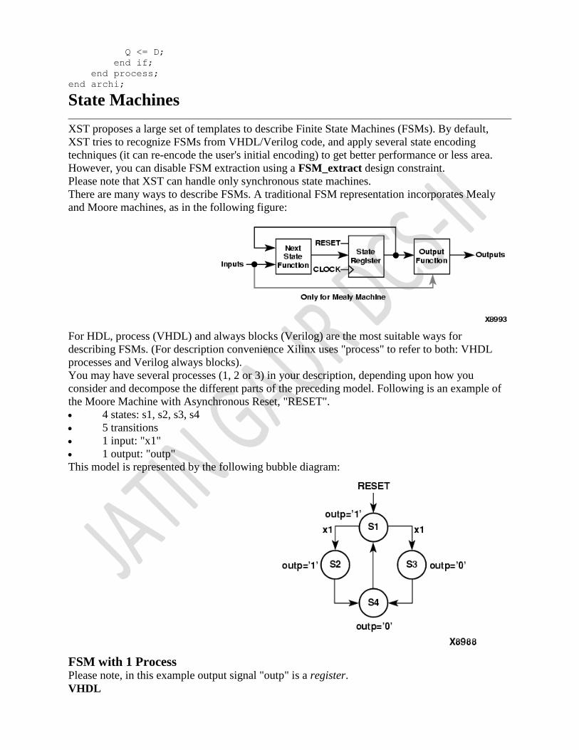
the Moore Machine with Asynchronous Reset, "RESET".
4 states: s1, s2, s3, s4
5 transitions
1 input: "x1"
1 output: "outp"
This model is represented by the following bubble diagram:
FSM with 1 Process Please note, in this example output signal "outp" is a register.
VHDL

Following is the VHDL code for an FSM with a single process. library IEEE;
use IEEE.std_logic_1164.all;
entity fsm is
port ( clk, reset, x1 : IN std_logic;
outp : OUT std_logic);
end entity;
architecture beh1 of fsm is
type state_type is (s1,s2,s3,s4);
signal state: state_type ;
begin
process (clk,reset)
begin
if (reset ='1') then
state <=s1; outp<='1';
elsif (clk='1' and clk'event) then
case state is
when s1 => if x1='1' then state <= s2;
else state <= s3;
end if;
outp <= '1';
when s2 => state <= s4; outp <= '1';
when s3 => state <= s4; outp <= '0';
when s4 => state <= s1; outp <= '0';
end case;
end if;
end process;
end beh1;
FSM with 2 Processes To eliminate a register from the "outputs", you can remove all assignments "outp <=..." from the
Clock synchronization section.
This can be done by introducing two processes as shown in the following figure.
VHDL
Following is VHDL code for an FSM with two processes. library IEEE;
use IEEE.std_logic_1164.all;
entity fsm is
port ( clk, reset, x1 : IN std_logic;
outp : OUT std_logic);
end entity;
architecture beh1 of fsm is
type state_type is (s1,s2,s3,s4);
signal state: state_type ;
begin
process1: process (clk,reset)
begin

if (reset ='1') then state <=s1;
elsif (clk='1' and clk'Event) then
case state is
when s1 => if x1='1' then state <= s2;
else state <= s3;
end if;
when s2 => state <= s4;
when s3 => state <= s4;
when s4 => state <= s1;
end case;
end if;
end process process1;
process2 : process (state)
begin
case state is
when s1 => outp <= '1';
when s2 => outp <= '1';
when s3 => outp <= '0';
when s4 => outp <= '0';
end case;
end process process2;
end beh1;
FSM with 3 Processes You can also separate the NEXT State function from the State Register:
Separating the NEXT State function from the State Register provides the following description:
VHDL
Following is the VHDL code for an FSM with three processes. library IEEE;
use IEEE.std_logic_1164.all;
entity fsm is
port ( clk, reset, x1 : IN std_logic;
outp : OUT std_logic);
end entity;
architecture beh1 of fsm is
type state_type is (s1,s2,s3,s4);
signal state, next_state: state_type ;
begin process1: process (clk,reset)
begin
if (reset ='1') then
state <=s1;
elsif (clk='1' and clk'Event) then
state <= next_state;
end if;
end process process1;

process2 : process (state, x1)
begin
case state is
when s1 => if x1='1' then
next_state <= s2;
else
next_state <= s3;
end if;
when s2 => next_state <= s4;
when s3 => next_state <= s4;
when s4 => next_state <= s1;
end case;
end process process2;
process3 : process (state)
begin
case state is
when s1 => outp <= '1';
when s2 => outp <= '1';
when s3 => outp <= '0';
when s4 => outp <= '0';
end case;
end process process3;
end beh1;
Shift Registers
In general a shift register is characterized by the following control and data signals, which are
fully recognized by XST:
clock
serial input
asynchronous set/reset
synchronous set/reset
synchronous/asynchronous parallel load
clock enable
serial or parallel output. The shift register output mode may be:
o serial: only the contents of the last flip-flop is accessed by the rest of the circuit
o parallel: the contents of one or several of flip-flops other than the last one, is
accessed
o shift modes: left, right, etc.
There are different ways to describe shift registers. For example in VHDL you can use:
concatenation operator shreg <= shreg (6 downto 0) & SI;
"for loop" construct for i in 0 to 6 loop
shreg(i+1) <= shreg(i);
end loop;
shreg(0) <= SI;
predefined shift operators for example, sll, srl.
8-bit Shift-Left Register with Positive-Edge Clock, Serial In, and Serial Out Note For this example, XST will infer SRL16.
The following table shows pin definitions for an 8-bit shift-left register with a positive-edge
clock, serial in, and serial out. IO Pins Description

C Positive-Edge Clock
SI Serial In
SO Serial Output
VHDL Code
Following is the VHDL code for an 8-bit shift-left register with a positive-edge clock, serial in,
and serial out. library ieee;
use ieee.std_logic_1164.all;
entity shift is
port(C, SI : in std_logic;
SO : out std_logic);
end shift;
architecture archi of shift is
signal tmp: std_logic_vector(7 downto 0);
begin
process (C)
begin
if (C'event and C='1') then
for i in 0 to 6 loop
tmp(i+1) <= tmp(i);
end loop;
tmp(0) <= SI;
end if;
end process;
SO <= tmp(7);
end archi;
8-bit Shift-Left Register with Negative-Edge Clock, Clock Enable, Serial In, and
Serial Out Note For this example, XST will infer SRL16E_1.
The following table shows pin definitions for an 8-bit shift-left register with a negative-edge
clock, clock enable, serial in, and serial out. IO Pins Description
C Negative-Edge Clock
SI Serial In
CE Clock Enable (active High)
SO Serial Output
VHDL Code
Following is the VHDL code for an 8-bit shift-left register with a negative-edge clock, clock
enable, serial in, and serial out. library ieee;
use ieee.std_logic_1164.all;
entity shift is port(C, SI, CE : in std_logic;
SO : out std_logic);
end shift;
architecture archi of shift is
signal tmp: std_logic_vector(7 downto 0);
begin
process (C)
begin
if (C'event and C='0') then
if (CE='1') then
for i in 0 to 6 loop
tmp(i+1) <= tmp(i);

end loop;
tmp(0) <= SI;
end if;
end if;
end process;
SO <= tmp(7);
end archi;
8-bit Shift-Left Register with Positive-Edge Clock, Asynchronous Clear, Serial
In, and Serial Out Note Because this example includes an asynchronous clear, XST will not infer SRL16.
The following table shows pin definitions for an 8-bit shift-left register with a positive-edge
clock, asynchronous clear, serial in, and serial out. IO Pins Description
C Positive-Edge Clock
SI Serial In
CLR Asynchronous Clear (active High)
SO Serial Output
VHDL Code
Following is the VHDL code for an 8-bit shift-left register with a positive-edge clock,
asynchronous clear, serial in, and serial out. library ieee;
use ieee.std_logic_1164.all;
entity shift is
port(C, SI, CLR : in std_logic;
SO : out std_logic);
end shift;
architecture archi of shift is
signal tmp: std_logic_vector(7 downto 0);
begin
process (C, CLR)
begin
if (CLR='1') then
tmp <= (others => '0');
elsif (C'event and C='1') then
tmp <= tmp(6 downto 0) & SI;
end if;
end process;
SO <= tmp(7);
end archi;
8-bit Shift-Left Register with Positive-Edge Clock, Synchronous Set, Serial In,
and Serial Out Note Because this example includes an asynchronous clear XST will not infer SRL16.
The following table shows pin definitions for an 8-bit shift-left register with a positive-edge
clock, synchronous set, serial in, and serial out. IO Pins Description
C Positive-Edge Clock
SI Serial In
S synchronous Set (active High)
SO Serial Output
VHDL Code
Following is the VHDL code for an 8-bit shift-left register with a positive-edge clock,
synchronous set, serial in, and serial out. library ieee;

use ieee.std_logic_1164.all;
entity shift is
port(C, SI, S : in std_logic;
SO : out std_logic);
end shift;
architecture archi of shift is
signal tmp: std_logic_vector(7 downto 0);
begin
process (C, S)
begin
if (C'event and C='1') then
if (S='1') then
tmp <= (others => '1');
else
tmp <= tmp(6 downto 0) & SI;
end if;
end if;
end process;
SO <= tmp(7);
end archi;
8-bit Shift-Left Register with Positive-Edge Clock, Serial In, and Parallel Out Note For this example XST will infer SRL16.
The following table shows pin definitions for an 8-bit shift-left register with a positive-edge
clock, serial in, and serial out. IO Pins Description
C Positive-Edge Clock
SI Serial In
PO[7:0] Parallel Output
VHDL Code
Following is the VHDL code for an 8-bit shift-left register with a positive-edge clock, serial in,
and serial out. library ieee;
use ieee.std_logic_1164.all;
entity shift is
port(C, SI : in std_logic;
PO : out std_logic_vector(7 downto 0));
end shift;
architecture archi of shift is
signal tmp: std_logic_vector(7 downto 0);
begin
process (C)
begin
if (C'event and C='1') then
tmp <= tmp(6 downto 0)& SI;
end if;
end process;
PO <= tmp;
end archi;
8-bit Shift-Left Register with Positive-Edge Clock, Asynchronous Parallel Load,
Serial In, and Serial Out Note For this example XST will infer SRL16.
The following table shows pin definitions for an 8-bit shift-left register with a positive-edge
clock, asynchronous parallel load, serial in, and serial out. IO Pins Description
C Positive-Edge Clock

SI Serial In
ALOAD Asynchronous Parallel Load (active High)
D[7:0] Data Input
SO Serial Output
VHDL Code
Following is VHDL code for an 8-bit shift-left register with a positive-edge clock, asynchronous
parallel load, serial in, and serial out. library ieee;
use ieee.std_logic_1164.all;
entity shift is
port(C, SI, ALOAD : in std_logic;
D : in std_logic_vector(7 downto 0);
SO : out std_logic);
end shift;
architecture archi of shift is
signal tmp: std_logic_vector(7 downto 0);
begin
process (C, ALOAD, D)
begin
if (ALOAD='1') then
tmp <= D;
elsif (C'event and C='1') then
tmp <= tmp(6 downto 0) & SI;
end if;
end process;
SO <= tmp(7);
end archi;
8-bit Shift-Left Register with Positive-Edge Clock, Synchronous Parallel Load,
Serial In, and Serial Out Note For this example XST will not infer SRL16.
The following table shows pin definitions for an 8-bit shift-left register with a positive-edge
clock, synchronous parallel load, serial in, and serial out. IO Pins Description
C Positive-Edge Clock
SI Serial In
SLOAD Synchronous Parallel Load (active High)
D[7:0] Data Input
SO Serial Output
VHDL Code
Following is the VHDL code for an 8-bit shift-left register with a positive-edge clock,
synchronous parallel load, serial in, and serial out. library ieee;
use ieee.std_logic_1164.all;
entity shift is
port(C, SI, SLOAD : in std_logic;
D : in std_logic_vector(7 downto 0);
SO : out std_logic);
end shift;
architecture archi of shift is
signal tmp: std_logic_vector(7 downto 0);
begin
process (C)
begin
if (C'event and C='1') then
if (SLOAD='1') then

tmp <= D;
else
tmp <= tmp(6 downto 0) & SI;
end if;
end if;
end process;
SO <= tmp(7);
end archi;
8-bit Shift-Left/Shift-Right Register with Positive-Edge Clock, Serial In, and
Parallel Out Note For this example XST will not infer SRL16.
The following table shows pin definitions for an 8-bit shift-left/shift-right register with a
positive-edge clock, serial in, and serial out. IO Pins Description
C Positive-Edge Clock
SI Serial In
LEFT_RIGHT Left/right shift mode selector
PO[7:0] Parallel Output
VHDL Code
Following is the VHDL code for an 8-bit shift-left/shift-right register with a positive-edge clock,
serial in, and serial out. library ieee;
use ieee.std_logic_1164.all;
entity shift is
port(C, SI, LEFT_RIGHT : in std_logic;
PO : out std_logic_vector(7 downto 0));
end shift;
architecture archi of shift is
signal tmp: std_logic_vector(7 downto 0);
begin
process (C)
begin
if (C'event and C='1') then
if (LEFT_RIGHT='0') then
tmp <= tmp(6 downto 0) & SI;
else
tmp <= SI & tmp(7 downto 1);
end if;
end if;
end process;
PO <= tmp;
end archi;