
Cotter Dam Seepage Remedial Works - GHD · Cotter Dam Seepage Remedial Works Damian Nott1, Martin...
10
ANCOLD 2015 Proceedings Contemporary Challenges for Dams Cotter Dam Seepage Remedial Works Damian Nott 1 , Martin Weir 2 and John Vida 3 1. Dams Engineer, GHD 2. Dams Engineer, GHD 3. NSW Engineering Manager, Lendlease With the construction of a new dam, the project is assumed to be complete following the commissioning stage. However it is not until after first filling that the behaviour and performance of the structure can be truly assessed. During the first filling of the enlarged Cotter Dam, an 87m high RCC gravity dam located west of Canberra, excessive seepage developed in the gallery, primarily from two of the monolith joints. Subsequent underwater investigations of the upstream face in these locations identified cracks offset from the monolith joints, originating close to the foundation. The investigation and rectification program implemented at the dam provides important industry learnings with regards to how unforeseen issues can arise and how they can be rectified. This paper will include a discussion regarding the possible causes of the cracking, and the potential risk mitigation measures that could be considered to avoid similar issues occurring in future projects. The discussion includes a review of options for design and positioning of transverse joints, along with possible measures to prevent cracking in future similar applications. The investigative methods utilised to determine the cause of the excessive seepage at the Cotter Dam are discussed. The options considered for remediating the seepage, and the final methodology adopted will also be presented. The paper will also discuss the challenges in undertaking the remedial works, and the lessons learnt for consideration on future projects. Keywords: RCC dam, excess seepage, transverse joint, investigation, crack Introduction The enlarged Cotter Dam is an 87m high roller compacted concrete (RCC) gravity dam, located west of Canberra on the Cotter River. The dam was constructed between 2009 and 2013 by the Bulk Water Alliance; comprising the owner Icon Water (formerly ACTEW Water), the designer GHD, and the constructor John Holland and Lendlease (formerly Abigroup). As the dam began to impound water, seepage through the transverse (monolith) joint drains was recorded in the dam gallery. The rate of seepage was initially within expected bounds. In the months following construction completion and dam commissioning, two instances of sudden increase in seepage flow rate occurred. The weirs monitoring seepage from the right abutment of the dam gallery recorded the increase in seepage, as shown in Figure 1. The telemetered seepage measurements at Weirs 1 and 2 had initially been relatively low, with a gradual increase as the reservoir began to fill. At the end of June 2014 the combined seepage from these weirs was in the order of 100L/min. On the 1 st July 2014 the seepage rate at Weirs 1 and 2 rose almost instantaneously; from 35L/min that morning to 130L/min by afternoon for Weir 2 alone. No significant increase in seepage rate was noted on the seepage weirs on the left abutment gallery at this time. Inspection in the dam gallery found excessive flow through the dam monolith joint at Ch. 205m. The joint had become pressurised, with water jetting through the joint where it crossed the gallery floor. In the weeks following the seepage rates at Weirs 1 and 2 levelled off and even decreased slightly, before continuing to increase gradually as the reservoir continued to fill. A second sudden increase in seepage rate at both weirs was again noted on the 2 nd August 2015. Inspection now found a similar increase of flow into the gallery through the transverse joint at Ch. 217m. Thereafter the increase in seepage rate at the two weirs was gradual and proportional to the rising reservoir level. Unsteady seepage recordings occurred from this time onward, as depicted in Figure 1, as a result of the turbulent flow conditions in the gallery drain, which affected the v-notch weir readings. The total seepage through the dam (including the contributions from the weirs on the left abutment) at the end of June 2014 was approximately 320L/min. By October 2014 this had increased approximately six fold, to almost 1,900L/min. The reservoir was 82% full (by volume) at this time. The excessive flow into the gallery from the monolith joints at Ch. 205m and Ch. 217m was creating a safety hazard in terms of access on the inclined gallery stairs.
Transcript of Cotter Dam Seepage Remedial Works - GHD · Cotter Dam Seepage Remedial Works Damian Nott1, Martin...

ANCOLD 2015 Proceedings
Contemporary Challenges for Dams
Cotter Dam Seepage Remedial Works
Damian Nott1, Martin Weir2 and John Vida3 1. Dams Engineer, GHD
2. Dams Engineer, GHD
3. NSW Engineering Manager, Lendlease
With the construction of a new dam, the project is assumed to be complete following the commissioning
stage. However it is not until after first filling that the behaviour and performance of the structure can be
truly assessed.
During the first filling of the enlarged Cotter Dam, an 87m high RCC gravity dam located west of
Canberra, excessive seepage developed in the gallery, primarily from two of the monolith joints.
Subsequent underwater investigations of the upstream face in these locations identified cracks offset from
the monolith joints, originating close to the foundation.
The investigation and rectification program implemented at the dam provides important industry learnings
with regards to how unforeseen issues can arise and how they can be rectified. This paper will include a
discussion regarding the possible causes of the cracking, and the potential risk mitigation measures that
could be considered to avoid similar issues occurring in future projects. The discussion includes a review
of options for design and positioning of transverse joints, along with possible measures to prevent cracking
in future similar applications.
The investigative methods utilised to determine the cause of the excessive seepage at the Cotter Dam are
discussed. The options considered for remediating the seepage, and the final methodology adopted will
also be presented. The paper will also discuss the challenges in undertaking the remedial works, and the
lessons learnt for consideration on future projects.
Keywords: RCC dam, excess seepage, transverse joint, investigation, crack
Introduction
The enlarged Cotter Dam is an 87m high roller compacted concrete (RCC) gravity dam, located west of Canberra on the
Cotter River. The dam was constructed between 2009 and 2013 by the Bulk Water Alliance; comprising the owner Icon
Water (formerly ACTEW Water), the designer GHD, and the constructor John Holland and Lendlease (formerly
Abigroup).
As the dam began to impound water, seepage through the transverse (monolith) joint drains was recorded in the dam
gallery. The rate of seepage was initially within expected bounds. In the months following construction completion and
dam commissioning, two instances of sudden increase in seepage flow rate occurred. The weirs monitoring seepage from
the right abutment of the dam gallery recorded the increase in seepage, as shown in Figure 1.
The telemetered seepage measurements at Weirs 1 and 2 had initially been relatively low, with a gradual increase as the
reservoir began to fill. At the end of June 2014 the combined seepage from these weirs was in the order of 100L/min. On
the 1st July 2014 the seepage rate at Weirs 1 and 2 rose almost instantaneously; from 35L/min that morning to 130L/min
by afternoon for Weir 2 alone. No significant increase in seepage rate was noted on the seepage weirs on the left
abutment gallery at this time. Inspection in the dam gallery found excessive flow through the dam monolith joint at Ch.
205m. The joint had become pressurised, with water jetting through the joint where it crossed the gallery floor.
In the weeks following the seepage rates at Weirs 1 and 2 levelled off and even decreased slightly, before continuing to
increase gradually as the reservoir continued to fill. A second sudden increase in seepage rate at both weirs was again
noted on the 2nd August 2015. Inspection now found a similar increase of flow into the gallery through the transverse
joint at Ch. 217m. Thereafter the increase in seepage rate at the two weirs was gradual and proportional to the rising
reservoir level. Unsteady seepage recordings occurred from this time onward, as depicted in Figure 1, as a result of the
turbulent flow conditions in the gallery drain, which affected the v-notch weir readings.
The total seepage through the dam (including the contributions from the weirs on the left abutment) at the end of June
2014 was approximately 320L/min. By October 2014 this had increased approximately six fold, to almost 1,900L/min.
The reservoir was 82% full (by volume) at this time. The excessive flow into the gallery from the monolith joints at Ch.
205m and Ch. 217m was creating a safety hazard in terms of access on the inclined gallery stairs.

ANCOLD 2015 Proceedings
Contemporary Challenges for Dams
Figure 1 – Seepage Measurements from the Right Abutment Gallery Weirs
The drainage channel that conveyed the combined seepage collected in the gallery to the Cotter River downstream was at
risk of exceeding capacity and flooding the gallery entrance floor. Remedial works were therefore required to address the
increase in seepage.
This paper discusses the investigative methods utilised to determine the cause of the excessive seepage at the Cotter
Dam. The options considered for remediating the seepage are also presented, as is the final approach adopted. The paper
will also discuss the challenges in undertaking the remedial works, and the lessons learnt for consideration on future
projects.
Seepage Investigation
Diver Investigation
Following the initial incremental increase in seepage rate in the gallery, divers were engaged to complete an inspection of
the monolith joints and surrounding upstream face of the dam. As the incremental increase in flow roughly coincided
with an increase in water level, it was suspected that the seepage was coming from the newly flooded areas of the dam, or
in close proximity to the level of the water in the reservoir at the time. Diving operations were therefore limited to 20m
below the reservoir level, which also reduced investigation costs. Water ingress to the joints was tested by spraying
diluted milk along the monolith joints and the exposed concrete face of the dam 3m either side. No obvious high seepage
areas were detected, and no particularly defective concrete was observed.
Remote Operated Vehicle (ROV) Investigation
Having failed to locate the source of the increased seepage at relatively shallow depths with divers, alternative
investigation methods were considered. With increased dive depth the allowable dive time is significantly impaired,
reducing the efficiency and increasing the cost of the investigation.
Considering the time, cost and quality of information required from the investigation, the option of the Remote Operated
Vehicle (ROV) was adopted. This ROV unit mobilised to site was capable of descending to depths of 90m (greater than
the maximum reservoir depth at Cotter Dam). The unit was fitted with four thrusters for control, had underwater lighting,
real time video footage, and the capability of fitting an injection nozzle to allow dye to be inserted into the reservoir at
suspected defect locations to further investigate any potential inflows.
The ROV inspection concentrated on the monolith joints at Ch. 205m and Ch. 217m, and the concrete immediately
adjacent. The unit was lowered first to the foundation interface at joint Ch. 217m, where a crack was detected
approximately 0.8m to the left of the joint, and extending 9m upwards subparallel to the joint.

ANCOLD 2015 Proceedings
Contemporary Challenges for Dams
Figure 2 – Dye Flowing into the Crack at Monolith Joint Ch. 217m
Upon detection of the crack, the dye nozzle was fitted to inject dye into the reservoir at the crack location, in an attempt
to ascertain whether the crack was taking in water. As shown in Figure 2, flow into the crack was clearly observed.
The process described was repeated with the ROV to investigate the joint at Ch. 205m and another crack was detected.
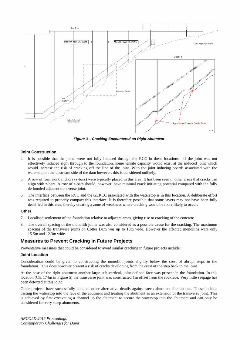
The cracks adjacent the joints at Ch. 217m and Ch. 205m were nine and four metres long respectively. Both of the cracks
were on the downslope side of the joints and extend sub-vertically back towards the monolith. The cracks were within
1m of the monolith joints and extended below the level of the monolith joint/foundation interface. Both joints were
estimated to be open up to 4mm wide. The location of the cracks found is shown in Figure 3.
Cause of Cracking
A change in the temperature of concrete leads to a change in its volume. The primary causes of temperature change in
large concrete dams are the heat of hydration of cement and supplementary cementitious materials (and the subsequent
dissipation of that heat) and changes in ambient temperature. Where restraint is present (either internal or external), this
leads to stresses and strains being developed in the concrete. When these exceed the tensile capacity of the concrete,
cracks develop.
This is a widely understood and well documented phenomenon in mass concrete structures (ACI, 2007). As a control
measure transverse joints are introduced into concrete dams to control the location and width of such cracking. For Cotter
Dam, the monolith joints were induced into the fresh RCC using a vibrating plate and plastic. It was intended for the
joints to extend the full thickness of the RCC. The upstream end of the joint was formed with rigid plastic boards which
were extended through the Grout Enriched RCC (GERCC) zone at the face of the dam and connected with the centrebulb
of the waterstop. The detail is shown in Figure 4.
The cracks are understood to have come about as a result of thermal shrinkage of the dam as it has cooled, however the
reason the cracks have occurred adjacent to the monolith joint rather than in the monolith joint itself is unclear. Possible
causes of the cracking are listed below. Any of these, or a combination, could have contributed to the cracking:
Joint Location
1. The position of the joint at Ch. 217m was at the top of an abrupt change in slope. This location was deliberately
selected as stress concentrations were anticipated in this location. It may be that the final joint location was slightly
beyond the crest of the slope; however this is not immediately apparent from site records (survey and photographs).
It also does not explain the cracking at Ch. 205m.
2. Subtle and/or localised irregularities in the foundation profile may have been present, leading to preferential cracking
of the concrete rather than opening of the monolith joint.
3. Shrinkage related movement of the concrete near the centre of the monolith may have led to a form of sympathetic
cracking.
ANCOLD 2015 Proceedings
Contemporary Challenges for Dams
Figure 3 – Cracking Encountered on Right Abutment
Joint Construction
4. It is possible that the joints were not fully induced through the RCC in these locations. If the joint was not
effectively induced right through to the foundation, some tensile capacity would exist at the induced joint which
would increase the risk of cracking off the line of the joint. With the joint inducing boards associated with the
waterstop on the upstream side of the dam however, this is considered unlikely.
5. A row of formwork anchors (z-bars) were typically placed in this area. It has been seen in other areas that cracks can
align with z-bars. A row of z-bars should, however, have minimal crack initiating potential compared with the fully
de-bonded adjacent transverse joint.
6. The interface between the RCC and the GERCC associated with the waterstop is in this location. A deliberate effort
was required to properly compact this interface. It is therefore possible that some layers may not have been fully
densified in this area, thereby creating a zone of weakness where cracking would be more likely to occur.
Other
7. Localised settlement of the foundation relative to adjacent areas, giving rise to cracking of the concrete.
8. The overall spacing of the monolith joints was also considered as a possible cause for the cracking. The maximum
spacing of the transverse joints on Cotter Dam was up to 18m wide. However the affected monoliths were only
15.5m and 12.3m wide.
Measures to Prevent Cracking in Future Projects
Preventative measures that could be considered to avoid similar cracking in future projects include:
Joint Location
Consideration could be given to constructing the monolith joints slightly below the crest of abrupt steps in the
foundation. This does however present a risk of cracks developing from the crest of the step back to the joint.
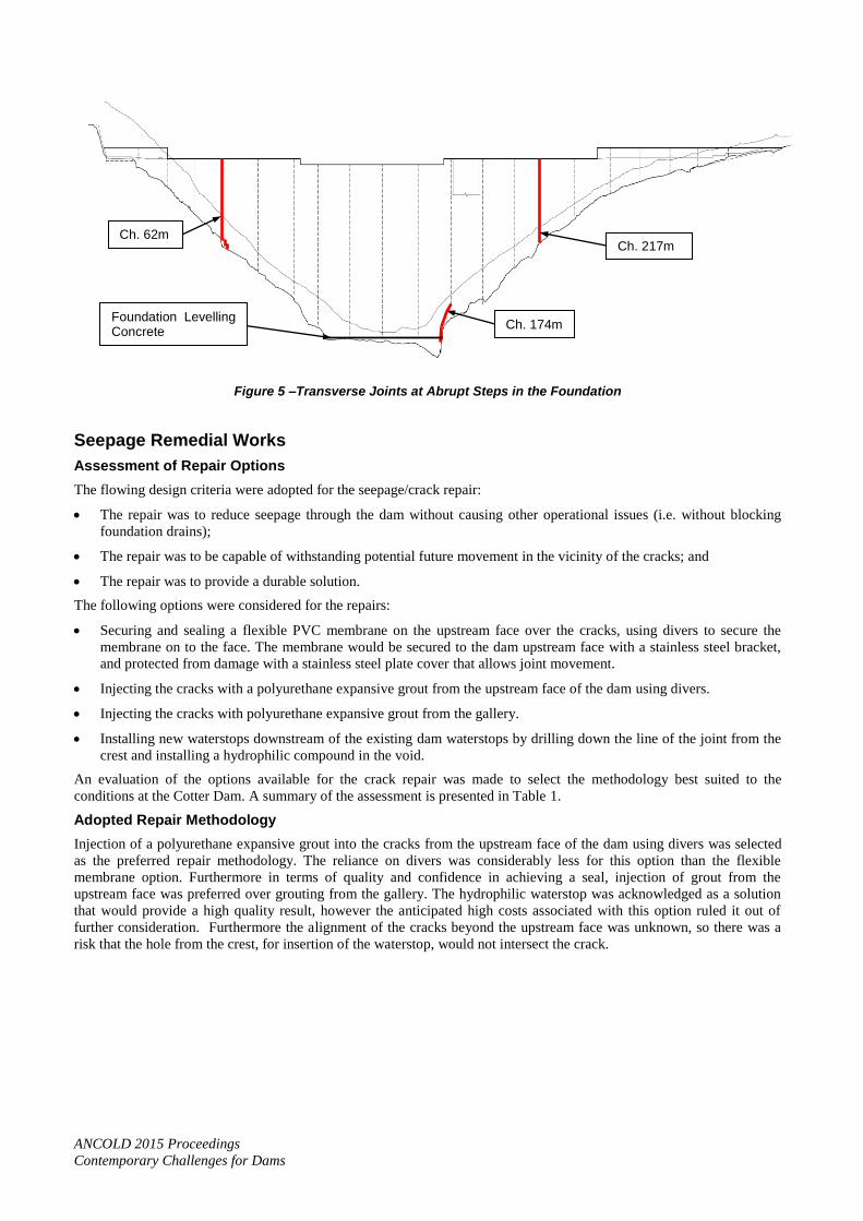
At the base of the right abutment another large sub-vertical, joint defined face was present in the foundation. In this
location (Ch. 174m in Figure 5) the transverse joint was constructed 1m offset from the rockface. Very little seepage has
been detected at this joint.
Other projects have successfully adopted other alternative details against steep abutment foundations. These include
casting the waterstop into the face of the abutment and treating the abutment as an extension of the transverse joint. This
is achieved by first excavating a channel up the abutment to secure the waterstop into the abutment and can only be
considered for very steep abutments.

ANCOLD 2015 Proceedings
Contemporary Challenges for Dams
Figure 4 – Transverse Joint Detail
Joint Spacing
In the vicinity of slope irregularities where a higher risk of unplanned cracking exists, consideration could be given to
reducing the transverse joint spacing in that location, effectively creating a narrower monolith. This reduces the
magnitude of any shrinkage in response to temperature change, which in turn limits the potential for unplanned cracking.
Slope Correction
Slope correction concrete can be used to eliminate abrupt foundation irregularities. This was adopted at Ch. 62m on
Cotter Dam as seen in Figure 5. Very little seepage has been detected at this joint. This work was also undertaken to
manage abutment seepage and as a non-critical path activity. Time and cost constraints may limit the use of this method
in other circumstances. In some cases slope correction can also be achieved through additional excavation, although the
orientation and extent of foundation defects may limit the potential for this form of treatment.
Reinforcement
Consideration could be given to adding reinforcement to the RCC and/or facing concrete in areas where residual risk is
considered to exist. Such contingency measures could be implemented with minor time and cost implications. This
technique was used successfully in other areas on Cotter Dam where the risk of cracking was identified (e.g. at conveyor
pedestals and other similar temporary works structures that were left in place and encapsulated within the dam).
Construction Process
If the risk of cracking in the vicinity of a particular waterstop is considered to be higher than usual, tighter construction
tolerances and increased supervision can be introduced to ensure additional care is taken in constructing the joint in that
location.
Induced Joint
Waterstop Drain
Waterstop
Plastic Board
ANCOLD 2015 Proceedings
Contemporary Challenges for Dams
Figure 5 –Transverse Joints at Abrupt Steps in the Foundation
Seepage Remedial Works
Assessment of Repair Options
The flowing design criteria were adopted for the seepage/crack repair:
The repair was to reduce seepage through the dam without causing other operational issues (i.e. without blocking
foundation drains);
The repair was to be capable of withstanding potential future movement in the vicinity of the cracks; and
The repair was to provide a durable solution.
The following options were considered for the repairs:
Securing and sealing a flexible PVC membrane on the upstream face over the cracks, using divers to secure the
membrane on to the face. The membrane would be secured to the dam upstream face with a stainless steel bracket,
and protected from damage with a stainless steel plate cover that allows joint movement.
Injecting the cracks with a polyurethane expansive grout from the upstream face of the dam using divers.
Injecting the cracks with polyurethane expansive grout from the gallery.
Installing new waterstops downstream of the existing dam waterstops by drilling down the line of the joint from the
crest and installing a hydrophilic compound in the void.
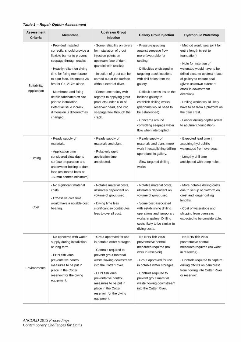
An evaluation of the options available for the crack repair was made to select the methodology best suited to the
conditions at the Cotter Dam. A summary of the assessment is presented in Table 1.
Adopted Repair Methodology
Injection of a polyurethane expansive grout into the cracks from the upstream face of the dam using divers was selected
as the preferred repair methodology. The reliance on divers was considerably less for this option than the flexible
membrane option. Furthermore in terms of quality and confidence in achieving a seal, injection of grout from the
upstream face was preferred over grouting from the gallery. The hydrophilic waterstop was acknowledged as a solution
that would provide a high quality result, however the anticipated high costs associated with this option ruled it out of
further consideration. Furthermore the alignment of the cracks beyond the upstream face was unknown, so there was a
risk that the hole from the crest, for insertion of the waterstop, would not intersect the crack.
Ch. 217m
Ch. 174m
Ch. 62m
Foundation Levelling Concrete
ANCOLD 2015 Proceedings
Contemporary Challenges for Dams
Table 1 – Repair Option Assessment
Assessment
Criteria Membrane
Upstream Grout
Injection Gallery Grout Injection Hydrophilic Waterstop
Suitability/
Application
- Provided installed
correctly, should provide a
flexible barrier to prevent
seepage through cracks.
- Heavily reliant on diving
time for fixing membrane
to dam face. Estimated 28
hrs for Ch. 217m alone.
- Membrane and fixing
details fabricated off site
prior to installation.
Potential issue if crack
dimension is different/has
changed.
- Some reliability on divers
for installation of grout
injection points on
upstream face of dam
(parallel with cracks).
- Injection of grout can be
carried out at the surface
without need of diver.
- Some uncertainty with
regards to applying grout
products under 40m of
reservoir head, and into
seepage flow through the
crack.
- Pressure grouting
against seepage flow
more favourable for
sealing.
- Difficulties envisaged in
targeting crack locations
with drill holes from the
gallery.
- Difficult access inside the
inclined gallery to
establish drilling works
(platforms would need to
be established).
- Concerns around
controlling seepage water
flow when intercepted.
- Method would seal joint for
entire length (crest to
foundation).
- Hole for insertion of
waterstop would have to be
drilled close to upstream face
of gallery to ensure seal
(given unknown extent of
crack in downstream
direction).
- Drilling works would likely
have to be from a platform on
the dam crest.
- Longer drilling depths (crest
to abutment foundation).
Timing
- Ready supply of
materials.
- Application time
considered slow due to
surface preparation and
underwater bolting to dam
face (estimated bolts at
150mm centres minimum).
- Ready supply of
materials and plant.
- Relatively rapid
application time
anticipated.
- Ready supply of
materials and plant, more
work in establishing drilling
operations in gallery.
- Slow targeted drilling
works.
- Expected lead time in
acquiring hydrophilic
waterstops from overseas.
- Lengthy drill time
anticipated with deep holes.
Cost
- No significant material
costs.
- Excessive dive time
would have a notable cost
bearing.
- Notable material costs,
ultimately dependent on
volume of grout used.
- Diving time less
significant so contributes
less to overall cost.
- Notable material costs,
ultimately dependent on
volume of grout used.
- Some cost associated
with establishing drilling
operations and temporary
works in gallery. Drilling
costs likely to be similar to
diving costs.
- More notable drilling costs
due to set up of platform on
crest and longer drilling
lengths.
- Cost of waterstops and
shipping from overseas
expected to be considerable.
Environmental
- No concerns with water
supply during installation
or long term.
- EHN fish virus
preventative control
measures to be put in
place in the Cotter
reservoir for the diving
equipment.
- Grout approved for use
in potable water storages.
- Controls required to
prevent grout material
waste flowing downstream
into the Cotter River.
- EHN fish virus
preventative control
measures to be put in
place in the Cotter
reservoir for the diving
equipment.
- No EHN fish virus
preventative control
measures required (no
work in reservoir).
- Grout approved for use
in potable water storages.
- Controls required to
prevent grout material
waste flowing downstream
into the Cotter River.
- No EHN fish virus
preventative control
measures required (no work
in reservoir).
- Controls required to capture
drilling offcuts on dam crest
from flowing into Cotter River
or reservoir.

ANCOLD 2015 Proceedings
Contemporary Challenges for Dams
Assessment
Criteria Membrane
Upstream Grout
Injection Gallery Grout Injection Hydrophilic Waterstop
Quality
- Some concerns with
sealing membrane
interface with:
Uneven upstream
dam surface;
Foundation interface.
- Grout would need
‘calibrating’ to ensure it
sets prior to being washed
through crack with
seepage flow.
- Grout would need
‘calibrating’ to ensure it
sets prior to being washed
through crack with
seepage flow.
- Concerns with regards to
difficulty in intercepting the
crack on the upstream
face when drilling from the
gallery.
- Alignment of drill holes
important to ensure
interception of seepage
through the monolith joint for
the full length of the hole.
Safety
- Management of safe
diving times and work over
and in water.
- Management of safe
diving times and work over
and in water.
- Safe measures for
mixing/pumping grout.
- Management of drilling
platform in gallery and
safe access to.
- Safe measures for
mixing/pumping grout.
- Management of drilling
platform on dam crest and
safe access to.
Application of Repair
Grouting of the cracks was to be undertaken in two stages. A hydrophobic polyurethane grout was to be injected first to
stem the seepage flow through the cracks. This grout reacts when in contact with water, producing a rigid foam.
Immediately after a hydrophilic polyurethane grout was to be injected; this reacts when in contact with water to form a
resilient flexible seal that accommodates ongoing crack movement.
The grouts to be applied rely on an accelerator to initiate expansion when they come into contact with water. The volume
of accelerator to be introduced into the grout depends on the environment in which the grouting works is being
undertaken, in terms of the temperature and the pressure. The grouting subcontractor undertook laboratory trials off site,
replicating the 9°C water temperature and 400 kPa pressure (approximate reservoir head at that time). This allowed a best
estimate of the accelerator dosage to be determined prior to mobilising to site.
The procedure for grout injection of the cracks at dam monolith Ch. 205m and Ch. 217m is summarised below:
1. Diver drills a 12mm diameter hole into the crack, offset by 150mm, as shown in Figure 6.
2. Diver inserts and secures injection packer into the drill hole.
3. Injection hose connected to the packer from the surface, and the hydrophobic polyurethane grout pumped from
surface.
4. Initial hydrophobic grouting discontinued when observed exiting the upstream face of the dam through the monolith
joint. Hydrophilic polyurethane grout then pumped into crack, at pressures up to 2,750kPa.
5. Once material observed coming out of the crack on the upstream face, or inside the dam gallery, grouting to cease.
6. Diver to move up or down crack 0.5m and start new injection point, repeating the above process until the length of
crack grouted.
7. Joint tested by spraying dye on upstream face for signs of residual seepage flow, additional injection points may be
required depending on outcome.

ANCOLD 2015 Proceedings
Contemporary Challenges for Dams
Figure 6 – Crack Grout Injection Hole Detail
Result and Lessons Learnt
The crack grouting operations at Cotter Dam were undertaken over a seven day period in October 2014. The success of
the treatment is demonstrated by the seepage reduction achieved. Prior to commencing grouting works the seepage
collected in the dam gallery totalled at approximately 1,900L/min. At demobilisation from site the total seepage had
reduced to 800L/min. In the months that followed, the seepage continued to decrease, to a low of 220L/min in mid-April
2015. The reduction in seepage is shown in Figure 7.
In undertaking the grouting works, some components of the work were more time consuming that originally anticipated.
With this knowledge some recommendations with regards to improvements can be made for future application of this
approach to sealing leaking cracks in concrete dams.
The short drill holes for insertion of the injection packer for grouting the cracks were drilled by the divers with a
hydraulic power drill. The time required to drill the holes ranged from five minutes up to fifteen minutes, depending on
the diver’s ability to achieve resistance to the drilling action. A means of supporting the divers against the upstream face
of the dam would have greatly improved the efficiency of the drilling works.
The primary time consuming component of the works was the grouting. During initial applications of the hydrophilic
polyurethane grout, the seepage flowrate through the cracks was such that the grout did not have time to react prior to
being washed through into the gallery. Increasing the accelerator dosage assisted, but ultimately a means of reducing the
flow through the cracks was sought. A flexible building putty was applied along the length of the crack on the dam
upstream face to reduce the inflow. This slowed the flow of the grout through the crack, thereby allowing the grout
expand and set within the crack as intended.
The advantage of grouting from the upstream face was the flexibility it offered. The crack observed at monolith joint Ch.
205m was approximately 5m longer at the time of grouting than when it was measured two months prior using the ROV.
Had alternative methods (such as the upstream PVC membrane) been adopted, significant downtime would have
occurred prior to installation for the dimensions of the bracket and membrane to be modified to suit the final dimensions
of the crack. Worst still, depending on the timing of the works, the patch could have been installed only to find that the
crack propagated beyond the extent of the repair soon thereafter.
Conclusions
Temperature change, thermal stresses and the potential for cracking is a widely understood phenomenon associated with
construction of large concrete dams. The forces at play are however complex and despite attempts to predict and manage
cracking by the spacing and strategic placement of transverse joints, on occasion unplanned cracking occurs. This was
the case at Cotter Dam. The unplanned cracking at Cotter Dam lead to excessive seepage developing in the gallery,
primarily from two of the monolith joints on the right abutment.
Several possible contributing factors have been identified as to why the cracking occurred including the exact positioning
of the transverse joints, the joint construction and other reasons.

ANCOLD 2015 Proceedings
Contemporary Challenges for Dams
Figure 7 – Cotter Dam Gallery Seepage
Alternative joint locations, targeted reduced joint spacing, slope correction treatment and reinforcement have been
identified as possible treatment measures to limit the risk of similar cracks occurring in future projects.
The use of both ROV technology coupled with divers enabled a cost effective means of investigation and treatment to be
achieved.
A range of possible treatment methodologies exist, each of which have their advantages and disadvantages. The optimum
solution is likely to vary from project to project. In the case of the Cotter Dam, where significant uncertainty existed with
cracking at considerable depth and with difficulties associated with access from other locations; grouting from the
reservoir offered the flexibility required. One of the cracks had propagated an additional 5m in length from when it was
initially inspected to when the repairs were undertaken, two months later. Had an alternative treatment methodology been
adopted this could have significantly impacted on the cost, time and effectiveness of the repair.
Ultimately the cracks were grouted from the reservoir using a combination of modern hydrophilic and hydrophobic
polyurethane grouts. The current technology is such that the chemistry can be adjusted to suit the intended application
and modifications can be made in the field depending on performance. This coupled with other simple measures allowed
for successful treatment to be achieved. The adopted methodology also allows for subsequent applications to be
undertaken, in the unlikely event this is required.
Ultimately the seepage from the dam has been reduced to approximately one tenth of what it was prior to grouting, a very
successful outcome. The total seepage through the dam is currently approximately 300L/min which is considered to be
well within acceptable limits for an 87m high RCC dam.
Acknowledgements
The authors acknowledge the permission granted by Icon Water for permitting publication of this paper.
References
American Concrete Institute, 2007. Report on Thermal and Volume Change Effects on Cracking in Mass Concrete.
ACI 207.2R-07. American Concrete Institute.