COTS Ceramic Capacitors: An Evaluation Report of the Parts ... · MIL-PRF-55681, as well as several...
13
Capacitor and Resistor Technology Symposium (CARTS) 2004 – San Antonio, TX COTS Ceramic Chip Capacitors: An Evaluation of the Parts and Assurance Methodologies Jay A. Brusse QSS Group, Incorporated NASA Goddard Space Flight Center Greenbelt, MD 20771 Phone: 301-286-2019 Fax: 301-286-9778 [email protected] Michael J. Sampson NASA Goddard Space Flight Center Greenbelt, MD 20771 Phone: 301-286-3335 Fax: 301-286-1667 [email protected] Abstract Commercial-Off-The-Shelf (COTS) multilayer ceramic chip capacitors (MLCCs) are continually evolving to reduce physical size and increase volumetric efficiency. Designers of high reliability aerospace and military systems are attracted to these attributes of COTS MLCCs and would like to take advantage of them while maintaining the high standards for long-term reliable operation they are accustomed to when selecting military qualified established reliability (MIL-ER) MLCCs (e.g., MIL- PRF-55681). However, MIL-ER MLCCs are not available in the full range of small chip sizes with high capacitance as found in today's COTS MLCCs. The objectives for this evaluation were to assess the long-term performance of small case size COTS MLCCs and to identify effective, lower-cost product assurance methodologies. Fifteen (15) lots of COTS X7R dielectric MLCCs from four (4) different manufacturers and two (2) MIL-ER BX dielectric MLCCs from two (2) of the same manufacturers were evaluated. Both 0805 and 0402 chip sizes were included. Several voltage ratings were tested ranging from a high of 50 volts to a low of 6.3 volts. The evaluation consisted of a comprehensive screening and qualification test program based upon MIL-PRF- 55681 (i.e., voltage conditioning, thermal shock, moisture resistance, 2000-hour life test, etc.). In addition, several lot characterization tests were performed including Destructive Physical Analysis (DPA), Highly Accelerated Life Test (HALT) and Dielectric Voltage Breakdown Strength. The data analysis included a comparison of the 2000-hour life test results (used as a metric for long-term performance) relative to the screening and characterization test results. Results of this analysis indicate that the long-term life performance of COTS MLCCs is variable -- some lots perform well, some lots perform poorly. DPA and HALT were found to be promising lot characterization tests to identify substandard COTS MLCC lots prior to conducting more expensive screening and qualification tests. The results indicate that lot- specific screening and qualification are still recommended for high reliability applications. One significant and concerning observation is that MIL- type voltage conditioning (100 hours at twice rated voltage, 125°C) was not an effective screen in removing infant mortality parts for the particular lots of COTS MLCCs evaluated. Introduction Multilayer ceramic chip capacitors (MLCCs) are found in essentially every class of electronic product application, including consumer, industrial, telecommunication and automotive. Historically, designers of high reliability aerospace and military electronic systems have selected military established reliability (MIL-ER) MLCCs from MIL-PRF-55681 or MIL-PRF-123 because of their stable construction, rigorous performance test requirements and quantified reliability. As in other industries, hi-rel MIL/Aerospace designers are striving to reduce the size, weight and cost of the electronic assemblies with little or no sacrifice to the long-term performance of the electronic components. Since their introduction, Commercial-Off-The-Shelf (COTS) MLCCs have continually evolved to reduce physical size and increase volumetric efficiency (capacitance per volume). Today, COTS MLCCs are readily available as small as 0402 (i.e., 40 mils by 20 mils) and 0201 chip sizes with 01005 (10 mils by 5 mils) chips now finding their way to market 1 . To accommodate low voltage applications, COTS MLCCs are also available with voltage ratings as low as 6.3 volts. One way COTS MLCC suppliers have increased volumetric efficiency is by reducing the dielectric thickness, which in turn provides space for additional dielectric layers/electrodes. With the increase in electrode count, the cost of the electrode materials becomes a more significant factor in the overall cost of the MLCCs. To remain cost competitive, many COTS suppliers have switched to lower cost Base Metal
Transcript of COTS Ceramic Capacitors: An Evaluation Report of the Parts ... · MIL-PRF-55681, as well as several...
Capacitor and Resistor Technology Symposium (CARTS) 2004 – San Antonio, TX
COTS Ceramic Chip Capacitors: An Evaluation of the Parts and Assurance Methodologies
Jay A. Brusse
QSS Group, Incorporated NASA Goddard Space Flight Center
Greenbelt, MD 20771 Phone: 301-286-2019 Fax: 301-286-9778
Michael J. Sampson NASA Goddard Space Flight Center
Greenbelt, MD 20771 Phone: 301-286-3335 Fax: 301-286-1667
Abstract Commercial-Off-The-Shelf (COTS) multilayer ceramic chip capacitors (MLCCs) are continually evolving to reduce physical size and increase volumetric efficiency. Designers of high reliability aerospace and military systems are attracted to these attributes of COTS MLCCs and would like to take advantage of them while maintaining the high standards for long-term reliable operation they are accustomed to when selecting military qualified established reliability (MIL-ER) MLCCs (e.g., MIL-PRF-55681). However, MIL-ER MLCCs are not available in the full range of small chip sizes with high capacitance as found in today's COTS MLCCs. The objectives for this evaluation were to assess the long-term performance of small case size COTS MLCCs and to identify effective, lower-cost product assurance methodologies. Fifteen (15) lots of COTS X7R dielectric MLCCs from four (4) different manufacturers and two (2) MIL-ER BX dielectric MLCCs from two (2) of the same manufacturers were evaluated. Both 0805 and 0402 chip sizes were included. Several voltage ratings were tested ranging from a high of 50 volts to a low of 6.3 volts. The evaluation consisted of a comprehensive screening and qualification test program based upon MIL-PRF-55681 (i.e., voltage conditioning, thermal shock, moisture resistance, 2000-hour life test, etc.). In addition, several lot characterization tests were performed including Destructive Physical Analysis (DPA), Highly Accelerated Life Test (HALT) and Dielectric Voltage Breakdown Strength. The data analysis included a comparison of the 2000-hour life test results (used as a metric for long-term performance) relative to the screening and characterization test results. Results of this analysis indicate that the long-term life performance of COTS MLCCs is variable -- some lots perform well, some lots perform poorly. DPA and HALT were found to be promising lot characterization tests to identify substandard COTS MLCC lots prior to conducting more expensive screening and
qualification tests. The results indicate that lot-specific screening and qualification are still recommended for high reliability applications. One significant and concerning observation is that MIL-type voltage conditioning (100 hours at twice rated voltage, 125°C) was not an effective screen in removing infant mortality parts for the particular lots of COTS MLCCs evaluated.
Introduction Multilayer ceramic chip capacitors (MLCCs) are found in essentially every class of electronic product application, including consumer, industrial, telecommunication and automotive. Historically, designers of high reliability aerospace and military electronic systems have selected military established reliability (MIL-ER) MLCCs from MIL-PRF-55681 or MIL-PRF-123 because of their stable construction, rigorous performance test requirements and quantified reliability. As in other industries, hi-rel MIL/Aerospace designers are striving to reduce the size, weight and cost of the electronic assemblies with little or no sacrifice to the long-term performance of the electronic components. Since their introduction, Commercial-Off-The-Shelf (COTS) MLCCs have continually evolved to reduce physical size and increase volumetric efficiency (capacitance per volume). Today, COTS MLCCs are readily available as small as 0402 (i.e., 40 mils by 20 mils) and 0201 chip sizes with 01005 (10 mils by 5 mils) chips now finding their way to market 1. To accommodate low voltage applications, COTS MLCCs are also available with voltage ratings as low as 6.3 volts. One way COTS MLCC suppliers have increased volumetric efficiency is by reducing the dielectric thickness, which in turn provides space for additional dielectric layers/electrodes. With the increase in electrode count, the cost of the electrode materials becomes a more significant factor in the overall cost of the MLCCs. To remain cost competitive, many COTS suppliers have switched to lower cost Base Metal
Capacitor and Resistor Technology Symposium (CARTS) 2004 – San Antonio, TX
Electrode (BME) constructions (e.g., Nickel electrodes) as opposed to the traditional Precious Metal Electrode (PME) constructions (e.g., Palladium or Palladium/Silver electrodes).2 In contrast, MIL-ER MLCCs are only available with PME constructions, have been limited to the 0805 case size for the smallest footprint for many years and the lowest voltage rating available is 50 volts. There are no indications that BME constructions, smaller sizes and/or lower voltage ratings will become MIL-qualified in the foreseeable future. As such, consideration and/or incorporation of COTS MLCCs are becoming more prevalent in hi-rel designs that call for smaller, lighter, or lower voltage rating capacitors.
Attributes of COTS vs. MIL-ER MLCCs
Table 1 compares attributes of COTS vs. MIL-ER MLCCs highlighting those attributes for which COTS are more attractive. In addition to their availability in smaller sizes with higher capacitance per volume, COTS MLCCs offer shorter delivery times and lower procurement costs. However, it is important to note that these last two attributes, can increase substantially if the end-user requires the COTS MLCCs to be subjected to MIL-type screening and qualification tests. In fact, this added testing can quickly raise the overall "cost of ownership" for COTS to levels higher than buying MIL-ER parts3. Table 2 lists some attributes of COTS vs. MIL-ER MLCCs, highlighting why selection of COTS MLCCs for high-reliability applications can pose a challenge. In order to achieve higher volumetric efficiency, the
construction attributes of COTS MLCCs tend to follow more aggressive design rules (e.g., thinner dielectrics, narrower end margins) compared to MIL-ER MLCCs. The methods used by manufacturers to qualify their COTS MLCCs and assess long-term reliability are non-standardized and may vary substantially from supplier to supplier or even from lot to lot within a single supplier's product portfolio. Finally, published failure rate levels and the details of qualification protocols are often not available for external review and may be subject to change without notice to the end-user. MIL-ER MLCCs, on the other hand, have a long-standing history of stable and conservative product designs/voltage ratings with qualification based upon rigorous and routine test and inspection. Material and process changes for MIL-ER MLCCs are reviewed by the military qualifying activity who then, in conjunction with the supplier, assesses what appropriate re-qualification measures are necessary before allowing the changes to be introduced for fielded products. Hi-rel users are generally afforded the opportunity to participate in audits, qualification reviews and specification revisions. Furthermore, product reliability levels of MIL-ER products are established, published and maintained through routine submissions of product to long-term life testing (2000 hours). From this overview it can be seen that COTS MLCCs offer both advantages and challenges to designers of hi-rel systems.
Table 1: Typical Benefits of COTS vs. MIL-ER MLCCs Attributes COTS MIL-ER (e.g., MIL-PRF-55681)
Capacitance per Volume Higher Lower
Smallest Chip Sizes 0201, 0402 (Common) 01005 (New to Market) 0805 (Smallest Available)
Lowest Voltage Ratings 6.3 Volts 50 Volts # of Sources Numerous Few Delivery-Time Days to Weeks** Weeks to Months Procurement Costs Pennies/Part** Dollars/Part
**Note: Delivery-Time and Procurement Costs for COTS May Increase Substantially if End User Requires MIL-Type Screening and Qualification
Table 2: Challenges of COTS vs. MIL-ER MLCCs Attributes COTS MIL-ER (e.g., MIL-PRF-55681)
Vendor Design Rules Variable Aggressive Stable Conservative
Qualification Basis Non-Standardized / Varies by Vendor & Product
Standardized / User Involvement through audits and specification
changes & coordination
Process / Material Change
More Frequent / Without Notice to User
Less Frequent / Requires Re-Qualification /
User Notification
Reliability ??? Published Failure Rates / Established Reliability (ER) as low as 0.001%/1000 Hrs

Capacitor and Resistor Technology Symposium (CARTS) 2004 – San Antonio, TX
Purpose of Evaluation A comprehensive evaluation has been performed to better understand COTS MLCCs and methodologies for their assurance. The primary objectives of this evaluation were to: 1. Assess the long-term performance of COTS
MLCCs intended for high reliability Military and Aerospace applications
2. Identify effective, lower-cost product assurance methodologies for COTS MLCCs capable of providing equivalent confidence as MIL-ER parts
In addition, COTS MLCCs with BME and PME designs were included in this investigation to explore potential differences between these two technologies in terms of long-term performance and effectiveness of assurance methodologies.
Experimental Procedure The basic concept used in this evaluation is shown in Figure 1. First, a total of 17 MLCC lots (15 COTS and 2 MIL-ER) were procured through authorized distributors. Samples from each lot were screened via 100-hours of voltage conditioning with survivors subjected to 2000-hours of life test as a formal measure of long-term performance. Test conditions for voltage conditioning and life test were in
accordance with the requirements of MIL-PRF-55681 (i.e., twice rated voltage @ 125°C). Life test performance was chosen as the primary reliability "metric" for this evaluation not only because of its use in MIL-PRF-55681, but also because three suppliers interviewed in detail confirmed its use for evaluating many of their COTS products. Other samples from each lot were subjected to a complete array of qualification tests also based upon the requirements of MIL-PRF-55681 (e.g., thermal shock, moisture resistance, resistance to solder heat, low voltage 85/85). Finally, samples were subjected to various "lot characterization" tests (not required by MIL-PRF-55681) including Highly Accelerated Life Test (HALT), Destructive Physical Analysis and Ultimate Voltage Breakdown Strength (UVBS). The results of all tests were analyzed and compared to the results of the 2000-hour life test. This comparison was done to judge whether any of these tests could be used as effective, lower-cost reliability "indicators" in lieu of performing the more costly, time-consuming life test. At the time of writing of this report, data from the voltage conditioning, life test, HALT, DPA and UVBS tests have been analyzed and are presented herein. Data from other MIL-PRF-55681 based qualification tests will be analyzed and reported in future technical reports.
Figure 1. MLCC Evaluation Approach

Capacitor and Resistor Technology Symposium (CARTS) 2004 – San Antonio, TX
Description of MLCCs Chosen for Evaluation Table 3 provides a description of the MLCCs evaluated. Fifteen (15) lots of X7R dielectric COTS MLCCs were procured from four different manufacturers. X7R dielectric was chosen because its temperature characteristic is suited for a wide range of military and aerospace environments (-55°C to 125°C) and general-purpose applications. All lots were procured from authorized distributors using vendor catalog part numbers defining standard commercial products (i.e., strictly COTS with no additional testing beyond the manufacturer's standard practices for COTS). For comparison purposes, two lots of BX dielectric MIL-ER MLCCs were procured from two Military qualified manufacturers (who are also represented among the four COTS suppliers).
Two MLCC chip sizes, 0805 (80 mils by 50 mils) and 0402 (40 mils by 20 mils), were included from each supplier. Also, two voltage ratings (50 volts and the lowest available from each supplier) were chosen for each chip size. In all cases (COTS and MIL), the MLCCs were representative of the maximum capacitance available from each supplier for the chosen chip size/voltage rating. Lots having the above attributes were selected because they likely represent the most difficult construction designs; thus presenting a worst-case assessment. At the same time, such lots are also among the most attractive to designers because they maximize volumetric efficiency. All lots procured were manufactured in 2001 or 2002 except for one lot that was made in 1999.
Table 3. Description of MLCCs Chosen for Evaluation
Mfr Lot # Cap (uF)
Rated Voltage
(V) Size Dielectric
Type
1 0.0039 50 04022 0.1000 50 08053 0.0220 16 0402
A
4 0.4700 16 0805
X7R
5 0.0056 16 04026 0.0039 50 0402B 7 0.1000 50 0805
X7R
8 0.0390 6.3 04029 0.0047 50 0402
10 1.0000 10 0805C
11 0.1200 50 0805
X7R
12 0.0100 6.3 040213 0.0015 50 040214 1.0000 6.3 0805
COTS
D
15 0.1000 50 0805
X7R
E 16 0.0180 50 0805MIL
F 17 0.0180 50 0805BX
*Note: Only three lots were tested from manufacturer B due to a distributor error in supplying the incorrect part for the fourth lot.

Capacitor and Resistor Technology Symposium (CARTS) 2004 – San Antonio, TX
Description of Test Methods
The evaluation test program was based upon the complete screening and qualification requirements of MIL-PRF-55681, as well as several non-standard lot characterization tests. Of the screening and qualification tests, Voltage Conditioning and Life Test have been analyzed and are discussed herein. For these two tests, parametric measurements of capacitance, dissipation factor (DF) and insulation resistance (IR) at room temperature were used to assess pass or fail. Limits for capacitance and DF were selected in accordance with the limits and tolerances per the manufacturer data sheets. Limits for IR were standardized across all manufacturers to the limits of MIL-PRF-55681 (e.g., 100 Gohms or 1 Gohm–uF, whichever is less). In all cases, the parts were inspected for capacitance, DF and IR to ensure they were within the manufacturer’s specified limits prior to screening or qualification testing. Destructive Physical Analysis (DPA), Highly Accelerated Life Test (HALT) and Ultimate Voltage Breakdown Strength (UVBS) were performed as lot characterization tests. Each of these tests is destructive in nature and should not be used for 100%
screening. A survey of the manufacturers found that the conditions for HALT and UVBS shown in Table 4 were commonly used. In particular, for HALT, a test temperature of 140°C in conjunction with either 6x rated voltage (parts rated <50V) or 8x rated voltage (parts rated at 50V) applied. Parts were monitored during test and the time to catastrophic short circuit failure was recorded as indicated by the interruption of a low amperage rated fuse in series with each part. Mounting of parts for voltage conditioning, life test and HALT was accomplished using a common commercial assembly practice. Test boards were constructed of 0.125-inch thick polyimide with EIA recommended pads for 0805 and 0402 chip sizes. Eutectic tin-lead solder paste (Sn63Pb37) with water-soluble flux was screened onto the boards using a 4-mil stencil. MLCCs were picked and placed onto the test boards directly from the manufacturer's original tape and reel. The solder reflow process was accomplished using an inline convection oven with 220°C pre-heat zones and a 310°C peak reflow zone. The parts and boards were cleaned with a deionized water washer to complete the process.
Table 4: Test Methods/Conditions Used in Evaluation Test Name Conditions Acceptance Criteria**
Screening and Qualification Tests (per MIL-PRF-55681) Voltage Conditioning
Voltage: 2x VRated Temp: 125°C Time: 100 Hours Sample Size: 162 parts
Capacitance Tolerance Dissipation Factor IR at Room Temp (100 Gohms or 1 Gohm – uF)
Life Test Voltage: 2x VRated, Temp: 125°C Time: 2000 Hours Sample Size: 90 parts
Delta Capacitance Dissipation Factor 30% of Initial IR at Room Temp
Lot Characterization Tests (per manufacturer guidance) Highly Accelerated Life Test (HALT)
Voltage: 6x VRated (when VRated < 50V) or, 8x VRated (when VRated = 50V), Temp: 140°C Time: 240 Hours Sample Size: 30 parts
# of Catastrophic Failures vs. Time
Destructive Physical Analysis (DPA)
EIA RS-469 or equivalent 5 parts
Measure Design and Construction Features Identify Defects
Voltage Breakdown Strength
Voltage: Ramp to Destruction Ramp Rate: 10 V/sec Temp: Room Ambient Sample Size: 20 parts
Record Breakdown Voltage
** Parametric limits per Vendor Data Sheet except for IR limits per MIL-PRF-55681

Capacitor and Resistor Technology Symposium (CARTS) 2004 – San Antonio, TX
Results and Discussion The following sections discuss the results obtained during this evaluation test program. The tabular results are presented in a manner conducive to comparing the results of screening and lot characterization testing with the results of 2000-hour life test in order to illuminate potential benefits of each test as an indicator of long-term performance. The term "Parametric" is used to identify lots containing one or more parts that failed to meet room temperature IR limits. Catastrophic failures are labeled as "# Short" to indicate the number of short circuit failures.
Voltage Conditioning and Life Test Results Table 5 shows the results of the voltage conditioning screen and the 2000-hour Life Test including interim results at 500 and 1000 hours of test. From each lot, 162 parts were tested to 100-hours of voltage conditioning as a screening inspection prior to life test. Of these 162 parts, 90 survivors were then subjected to the 2000-hour life test. Capacitance, DF and IR at room temperature were measured before and after test to judge pass or fail. Five (5) of the 15 COTS MLCC lots experienced at least one part failure (parametric and/or catastrophic) during voltage conditioning. Two (2) of these five (5)
lots experienced either one or two catastrophic shorts (as noted) while the other three (3) lots contained slight parametric rejects only. These results were not considered to be very significant when reviewed independent of the subsequent life test results. However, when compared to life test performance, some disturbing observations were made. During the 2000-hour life test, eight (8) of the 15 COTS MLCC lots were considered rejectable due to excessive parametric and/or catastrophic failures. Five (5) of these lots experienced catastrophic shorts at test durations ranging from 500 through 2000 hours. These results were particularly disturbing because failures were observed at all stages of life test despite attempts to screen out substandard parts via 100-hours of voltage conditioning. Furthermore, life test failures were observed for at least one lot from each of the four COTS suppliers evaluated. This observation suggests that 100-hours of voltage conditioning is not an effective screening inspection for COTS MLCCs. The two MIL-ER MLCC lots experienced no failures (parametric or catastrophic) during either voltage conditioning or life test. These results were expected because the parts “as-received” had already been voltage conditioned by the manufacturer.
Table 5: Voltage Conditioning vs. Life Test Results
Mfr Lot # Cap
(uF)
Rated Voltage
(V) Size
100 Hrs Volt
Condition
500 Hrs Life Test
1000 Hrs Life Test
2000 Hrs Life Test
Life Test Disposition
1 0.0039 50 0402 Parametric Parametric Parametric Parametric Borderline2 0.1000 50 0805 Pass Pass Pass Pass Pass 3 0.0220 16 0402 Pass Pass Parametric Parametric Borderline
A
4 0.4700 16 0805 Pass Pass Pass Pass Pass
5 0.0056 16 0402 Pass Pass Pass Pass Pass 6 0.0039 50 0402 Pass Pass Pass Parametric BorderlineB 7 0.1000 50 0805 1 Short Pass Pass 1 Short Fail
8 0.0390 6.3 0402 Pass Pass Pass Pass Pass 9 0.0047 50 0402 Parametric Parametric 1 Short 12 Shorts Fail
10 1.0000 10 0805 2 Shorts 1 Short Parametric Parametric Fail C
11 0.1200 50 0805 Pass 1 Short 1 Short 1 Short Fail
12 0.0100 6.3 0402 Pass Pass Pass Pass Pass 13 0.0015 50 0402 Pass Pass Pass Pass Pass 14 1.0000 6.3 0805 Parametric 1 Short 2 Shorts 1 Short Fail
COTS
D
15 0.1000 50 0805 Pass Pass Pass Pass Pass
E 16 0.0180 50 0805 Pass Pass Pass Pass Pass MIL
F 17 0.0180 50 0805 Pass Pass Pass Pass Pass
NOTE: Failures shown on this table refer to room temperature IR failures only. Shorts counted at each segment of the test are not counted again nor carried over to the next segment. For example, Lot D-14 had a total of four (4) shorts through 2000 hours of life test.

Capacitor and Resistor Technology Symposium (CARTS) 2004 – San Antonio, TX
Highly Accelerated Life Test (HALT) Results Figure 2 and Table 6 show the results of the highly accelerated life test (HALT). Thirty (30) parts from each lot were subjected to the HALT conditions described in Table 4. In Figure 2, the cumulative percentage of failures vs. time on HALT is plotted. To facilitate a comparison of HALT performance with standard life testing, the five (5) lots that experienced one or more shorts on standard life test are highlighted with a circle in the figure. In Table 6, the HALT performance of each lot has been assessed as either “good”, “moderate” or “poor” based upon their performance relative to all other lots tested. For example, Lots C-9, C-10, C-11 and D-14 were judged to be “poor” HALT performers due to the relatively high percentage of failures during test. “Poor” performance during HALT provided a good predictor of lots having rejectable 2000-hour life test performance (i.e., Lots C-9, C-10, C-11 and D-14). While lots having “good” HALT performance (i.e., zero or very few failures) tend to “pass” the standard
life test, the correlation was not perfect. For example, Lots A-3, B-6 and especially B-7 all had very “good” HALT results, but their standard life test performance was judged to be “borderline” to “failing”. Note that there were no lots that were considered poor for HALT that passed life test. Computation of acceleration factors for HALT based upon this evaluation were attempted, but the results were deemed to be inconclusive due to the insufficient number of failures produced across all lots. Nevertheless, the qualitative comparison of results suggests that HALT can be a useful lot characterization test to predict poor life test performance. HALT’s small sample size, short duration, and relatively low cost (except for non-recurring engineering costs) make it an attractive tool to consider for pre-qualification assessment to eliminate substandard lots from further consideration. More experimentation and analysis is necessary in order to refine the test conditions and assign appropriate accept/reject criteria.
Lots W
Figure 2: Highly Accelerated Life Test (HALT) Results
ith Shorts During Std Life Test
=

Capacitor and Resistor Technology Symposium (CARTS) 2004 – San Antonio, TX
Table 6: Highly Accelerated Life Test (HALT) vs. Life Test Results
Mfr Lot # Cap (uF)
Rated Voltage
(V) Size Highly Accelerated
Life Test (HALT) Life Test
Disposition
1 0.0039 50 0402 Moderate Borderline 2 0.1000 50 0805 Good Pass 3 0.0220 16 0402 Good Borderline
A
4 0.4700 16 0805 Good Pass
5 0.0056 16 0402 Good Pass 6 0.0039 50 0402 Good Borderline B 7 0.1000 50 0805 Good Fail
8 0.0390 6.3 0402 Good Pass 9 0.0047 50 0402 Poor Fail
10 1.0000 10 0805 Poor Fail C
11 0.1200 50 0805 Poor Fail
12 0.0100 6.3 0402 Good Pass 13 0.0015 50 0402 Good Pass 14 1.0000 6.3 0805 Poor Fail
COTS
D
15 0.1000 50 0805 Good Pass
E 16 0.0180 50 0805 Good Pass MIL
F 17 0.0180 50 0805 Good Pass
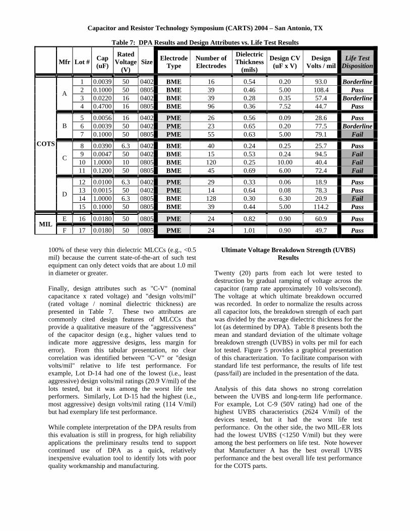
Destructive Physical Analysis (DPA) Results Each MLCC lot was sampled for DPA and construction analysis. Five capacitors per lot were randomly selected and cross-sectioned with inspection based upon EIA-469. Note that the DPA was done on only one plane, so the “quality” of the ceramic was based solely on that plane. Inspection consisted of optical microscopy to measure critical design features such as the thicknesses of the dielectric, cover plate, end margins and electrodes. Checks were made to identify workmanship defects such as delaminations, voids, cracks and inclusions. Optical microscopy was augmented by scanning electron microscopy (SEM) with energy dispersive spectroscopy (EDS) to identify lots manufactured using BME vs. PME materials and processes. No attempt was made to characterize the lots or to look for defects outside of the single plane of cross-section. Table 7 provides some of the findings of the DPA and construction analysis along with the lot disposition for life test. Some general discussion of the DPA observations is provided below, but a comprehensive understanding of these observations may not be possible until failure analysis of life test failures can be completed.
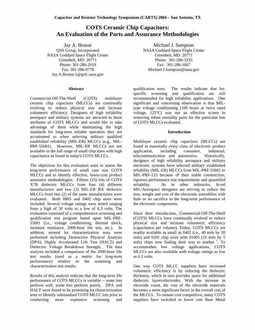
Generally speaking, the DPA found the COTS MLCC lots to be of good quality with consistent construction features. The ceramic dielectric, for the most part, looked dense and uniform. The electrodes were continuous, and contact between electrodes and terminations were solid. Voids were observed in the terminations of several COTS lots. As expected, the DPA showed the MIL-ER lots to be of sound quality (both dielectric and termination) with no defects observed. Figure 3 shows cross-section images to illustrate the general observations for COTS and MIL-ER MLCCs.
Capacitor and Resistor Technology Symposium (CARTS) 2004 – San Antonio, TX
Lot A-2
Lot E-16
Figure 3: Typical DPA Observations for COTS (Mfr "A" Lot 2) and MIL-ER (Mfr "E" Lot 16) MLCCs
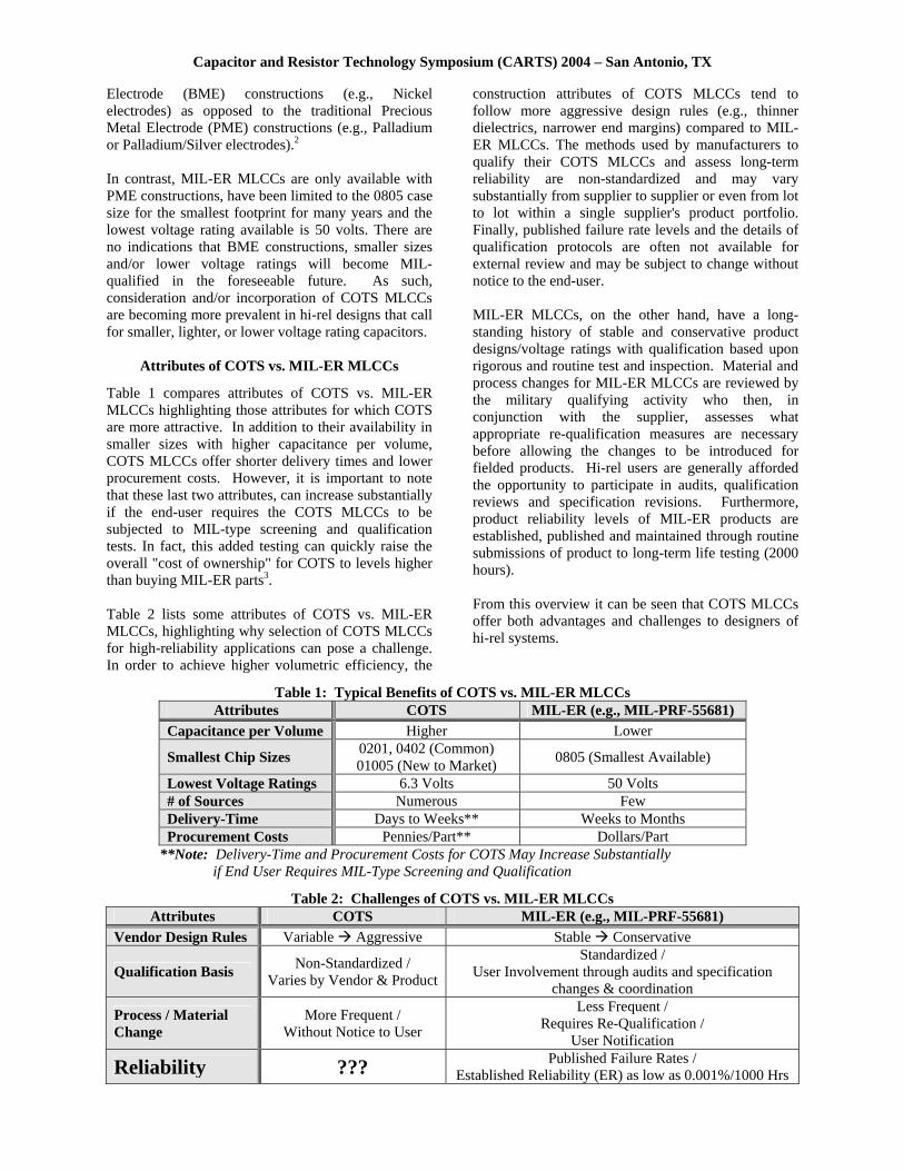
Figure 4. Delamination found during DPA of Lot C-9
One significant exception to the above general findings was observed during DPA of Lot C-9 where a significant delamination was found (Figure 4). As noted in Table 5, Lot C-9 also had the worst overall life test performance of the lots tested as shown by 13 short circuits out of 90 parts tested (12 shorts occurred between 1000 and 2000 hours of test). Although failure analysis of parts from Lot C-9 has not yet been performed, indications from other COTS MLCC testing programs have shown internal defects as the predominant cause of catastrophic shorting.4 Direct failure analysis of life test failures is planned to assess root cause. The SEM/EDS revealed that ten (10) of the fifteen (15) COTS MLCC lots were made using BME technology. The remaining five (5) COTS lots plus the two (2) MIL-ER lots were made using PME technology. Note: Direct analysis of construction was required to identify BME vs. PME lots since catalog and part number schema for all four suppliers provide no indication of this construction feature. In fact, of the four (4) COTS lots from Manufacturer D, two were BME and two were PME. A simple comparison of electrode technology vs. life test disposition for the COTS lots shows that 4 out of
10 BME lots failed life test compared to 1 out of 5 PME lots. This comparison alone does not appear to indicate any significant differences between BME vs. PME regarding long-term life performance. The authors intend to perform failure analyses in part to assess whether the different electrode technologies/processing may be important factors affecting long-term performance. Table 7 shows various design attributes quantified during the DPA of the MLCCs evaluated. As expected, the COTS MLCCs were found to have thinner dielectrics and higher electrode counts compared to the MIL-ER MLCCs in order to achieve the high capacitance values offered in the 0402 and 0805 chip sizes. For example, the thinnest 50 volt rated COTS lot (A-15) had a dielectric thickness of 0.44 mil compared to 0.82 mil for the thinnest 50 volt MIL-ER lot (Lot E-16). The thinner dielectrics did not necessarily translate to unreliability as indicated by the life test results. However, with thinner dielectrics, the margin for errors (in this case manufacturing defects) is not high; hence, internal defects may present unpredictable latencies as reflected in the life test results. In addition, conventional non-destruct testing such as ultrasonic scanning will not be useful in identifying lots containing voids that span even
Capacitor and Resistor Technology Symposium (CARTS) 2004 – San Antonio, TX
Table 7: DPA Results and Design Attributes vs. Life Test Results
Mfr Lot # Cap
(uF)
Rated Voltage
(V) Size Electrode
Type Number of Electrodes
DielectricThickness
(mils)
Design CV (uF x V)
Design Volts / mil
Life Test Disposition
1 0.0039 50 0402 BME 16 0.54 0.20 93.0 Borderline2 0.1000 50 0805 BME 39 0.46 5.00 108.4 Pass 3 0.0220 16 0402 BME 39 0.28 0.35 57.4 Borderline
A
4 0.4700 16 0805 BME 96 0.36 7.52 44.7 Pass
5 0.0056 16 0402 PME 26 0.56 0.09 28.6 Pass 6 0.0039 50 0402 PME 23 0.65 0.20 77.5 BorderlineB 7 0.1000 50 0805 PME 55 0.63 5.00 79.1 Fail
8 0.0390 6.3 0402 BME 40 0.24 0.25 25.7 Pass 9 0.0047 50 0402 BME 15 0.53 0.24 94.5 Fail
10 1.0000 10 0805 BME 120 0.25 10.00 40.4 Fail C
11 0.1200 50 0805 BME 45 0.69 6.00 72.4 Fail
12 0.0100 6.3 0402 PME 29 0.33 0.06 18.9 Pass 13 0.0015 50 0402 PME 14 0.64 0.08 78.3 Pass 14 1.0000 6.3 0805 BME 128 0.30 6.30 20.9 Fail
COTS
D
15 0.1000 50 0805 BME 39 0.44 5.00 114.2 Pass
E 16 0.0180 50 0805 PME 24 0.82 0.90 60.9 Pass MIL
F 17 0.0180 50 0805 PME 24 1.01 0.90 49.7 Pass
100% of these very thin dielectric MLCCs (e.g., <0.5 mil) because the current state-of-the-art of such test equipment can only detect voids that are about 1.0 mil in diameter or greater. Finally, design attributes such as "C-V" (nominal capacitance x rated voltage) and "design volts/mil" (rated voltage / nominal dielectric thickness) are presented in Table 7. These two attributes are commonly cited design features of MLCCs that provide a qualitative measure of the "aggressiveness" of the capacitor design (e.g., higher values tend to indicate more aggressive designs, less margin for error). From this tabular presentation, no clear correlation was identified between "C-V" or "design volts/mil" relative to life test performance. For example, Lot D-14 had one of the lowest (i.e., least aggressive) design volts/mil ratings (20.9 V/mil) of the lots tested, but it was among the worst life test performers. Similarly, Lot D-15 had the highest (i.e., most aggressive) design volts/mil rating (114 V/mil) but had exemplary life test performance. While complete interpretation of the DPA results from this evaluation is still in progress, for high reliability applications the preliminary results tend to support continued use of DPA as a quick, relatively inexpensive evaluation tool to identify lots with poor quality workmanship and manufacturing.
Ultimate Voltage Breakdown Strength (UVBS) Results
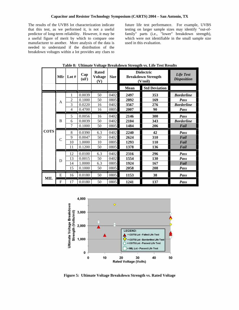
Twenty (20) parts from each lot were tested to destruction by gradual ramping of voltage across the capacitor (ramp rate approximately 10 volts/second). The voltage at which ultimate breakdown occurred was recorded. In order to normalize the results across all capacitor lots, the breakdown strength of each part was divided by the average dielectric thickness for the lot (as determined by DPA). Table 8 presents both the mean and standard deviation of the ultimate voltage breakdown strength (UVBS) in volts per mil for each lot tested. Figure 5 provides a graphical presentation of this characterization. To facilitate comparison with standard life test performance, the results of life test (pass/fail) are included in the presentation of the data. Analysis of this data shows no strong correlation between the UVBS and long-term life performance. For example, Lot C-9 (50V rating) had one of the highest UVBS characteristics (2624 V/mil) of the devices tested, but it had the worst life test performance. On the other side, the two MIL-ER lots had the lowest UVBS (<1250 V/mil) but they were among the best performers on life test. Note however that Manufacturer A has the best overall UVBS performance and the best overall life test performance for the COTS parts.
Capacitor and Resistor Technology Symposium (CARTS) 2004 – San Antonio, TX
The results of the UVBS lot characterization indicate that this test, as we performed it, is not a useful predictor of long-term reliability. However, it may be a useful figure of merit by which to compare one manufacturer to another. More analysis of the data is needed to understand if the distribution of the breakdown voltages within a lot provides any clues to
future life test performance. For example, UVBS testing on larger sample sizes may identify "out-of-family" parts (i.e., "lower" breakdown strength), which were not identifiable in the small sample size used in this evaluation.
Table 8: Ultimate Voltage Breakdown Strength vs. Life Test Results
Mfr Lot # Cap (uF)
Rated Voltage
(V) Size
Dielectric Breakdown Strength
(V/mil)
Life Test Disposition
Mean Std Deviation
1 0.0039 50 0402 2497 353 Borderline 2 0.1000 50 0805 2892 169 Pass 3 0.0220 16 0402 3567 276 Borderline
A
4 0.4700 16 0805 2007 90 Pass
5 0.0056 16 0402 2146 300 Pass 6 0.0039 50 0402 2104 343 Borderline B 7 0.1000 50 0805 1484 206 Fail
8 0.0390 6.3 0402 2240 42 Pass 9 0.0047 50 0402 2624 310 Fail
10 1.0000 10 0805 1293 110 Fail C
11 0.1200 50 0805 1378 136 Fail
12 0.0100 6.3 0402 2316 296 Pass 13 0.0015 50 0402 1554 130 Pass 14 1.0000 6.3 0805 1924 167 Fail
COTS
D
15 0.1000 50 0805 2058 208 Pass
E 16 0.0180 50 0805 1153 38 Pass MIL
F 17 0.0180 50 0805 1241 137 Pass
Figure 5: Ultimate Voltage Breakdown Strength vs. Rated Voltage

Capacitor and Resistor Technology Symposium (CARTS) 2004 – San Antonio, TX
Conclusions For the multilayer ceramic chip capacitors (MLCCs) tested, this evaluation supports the following conclusions based upon the needs and expectations of high reliability military and aerospace applications: 1. Long-term performance of the MIL-ER MLCCs
was excellent. 2. Long-term performance of the COTS MLCCs was
variable. Eight (8) of 15 lots had unsatisfactory 2000-hour life test results despite having been screened via 100-hours of voltage conditioning prior to life test. Of these 8 lots, five (5) experienced one (1) or more catastrophic short circuit failures out of 90 parts tested at time intervals ranging from 100 to 2000 hours of test.
3. Destructive Physical Analysis (DPA) was found to be a useful indicator of very poor quality lots. It's quick turnaround and relative low-cost makes it an attractive test to eliminate substandard lots from further consideration prior to conducting expensive screening/qualification.
4. Highly Accelerated Life Test (HALT) was found to be a useful lot characterization tool to identify substandard MLCC lots prior to screening and qualification testing. More experimentation is needed to refine test conditions and develop quantitative lot accept/reject criteria.
5. Traditional MIL-type Voltage Conditioning (twice rated voltage, 125°C for 100 hours) was NOT an effective screen for the COTS MLCCs. Eight (8) of 15 lots subjected to this screen had unsatisfactory 2000-hour life test results.
Recommendations For high reliability military and aerospace applications that are considering the use of COTS MLCCs, the authors recommend the lot acceptance test flow of Figure 6. If MIL-ER MLCCs (e.g., MIL-PRF-55681 or MIL-PRF-123) are procured, the results of this test evaluation program support the recommendation to procure, then "use as-is", except in extremely critical applications where unique screening and/or qualification testing may be warranted. If COTS MLCCs are being considered, then following Steps 1 and 2 of the flow is encouraged. To maximize cost and time-saving benefits, the lot characterization tests of Step 1 should be completed prior to committing any resources to Step 2. In Step 1, lot characterization testing via both DPA and HALT is recommended in order to eliminate substandard lots from further consideration. Only lots that successfully pass both DPA and HALT should be processed via Step 2 screening and qualification. In Step 2, all parts should be 100% screened via voltage conditioning with a mandatory sample submitted to long-term life test. Lots failing life test should be rejected regardless of the results of voltage conditioning. For lots that pass life test, the parts surviving the voltage conditioning screen may be considered for use. In Step 2, other qualification tests may be warranted in addition to life test. Analysis of results from tests such as thermal shock, resistance to solder heat, moisture resistance and low voltage 85/85 could not be completed in time for incorporation in this report.
Figure 6. Recommended Lot Acceptance Test Flow for MLCCs Intended for Hi-Rel Applications

Capacitor and Resistor Technology Symposium (CARTS) 2004 – San Antonio, TX
The authors suggest that further experimentation be conducted to assess the following: 1. Alternate conditions for voltage conditioning
(e.g., higher or lower voltages and/or different durations) to determine a more effective screening test for COTS MLCCs
2. Refinement of test conditions and accept/reject conditions for HALT
3. Derating principles applicable to COTS vs. MIL-ER MLCCs
Future Work
Analysis of the test results from this evaluation is continuing. In future technical reports, the authors plan to: 1. Perform failure analysis (FA) on various parts
evaluated during this investigation. In particular, FA on Lot C-9 will be performed to identify potential reasons for poor life test performance of this lot despite having one of the highest voltage breakdown strength characteristics of the lots examined.
2. Review the performance of COTS Base Metal Electrode (BME) vs. COTS Precious Metal Electrode (PME) MLCCs
3. More closely analyze the design/construction attributes of COTS MLCCs vs. long term performance
4. Analyze other qualification and characterization tests such as thermal shock, resistance to solder heat, moisture resistance, low voltage 85/85, terminal strength and acoustic microscopy
Acknowledgments This work was performed under contract to the NASA EEE Parts Assurance Group (NEPAG). All testing services were expertly provided by NAVSEA Crane. We acknowledge Mike Rader (NAVSEA-Crane), Jocelyn Siplon (The Aerospace Corporation) and Ron Herin (Jet Propulsion Laboratory) for their technical contributions throughout the course of this evaluation. We also express our gratitude to the capacitor manufacturers for their cooperation and guidance. References 1) "Commercialization of 01005 Size Chip
Monolithic Ceramic Capacitors", Murata Press Release NR0392E, October 2, 2003, http://www.murata.com/ninfo/nr0392e.html
2) H. Park, D. McBrayer, "Base Metal Electrode Multialyer Ceramic Capacitors", Kemet TechTopics, Vol. 7, No. 4, November 1997
3) M. Sampson, "Cost/Benefit of Using COTS EEE Parts in Space", 2003 Commercialization of Military and Space Electronics (CMSE) Conference
4) Private Communications, J. Siplon, The Aerospace Corporation, January 2004