Cost-effective single-hub WDM ring networks: A proposal and … · Cost-effective single-hub WDM...
24
Cost-effective single-hub WDM ring networks: A proposal and analysis Nizar Bouabdallah a, * , Harry Perros b a INRIA, Campus Universitaire de Beaulieu, 35042 Rennes Cedex, France b Computer Science Department, NC State University, Raleigh, NC 27995-8206, United States Received 22 September 2006; received in revised form 19 February 2007; accepted 20 April 2007 Available online 6 May 2007 Responsible Editor: A. Kamal Abstract In this paper, we study a new concept of traffic grooming in wavelength-division multiplexing (WDM) ring networks that aims at eliminating both the bandwidth underutilization and the scalability concerns that are typical of all-optical wavelength routed ring networks. Our objective is to reduce the network cost while preserving the benefits of all-optical WDM ring networks. In order to assess the efficiency of our proposal, all underlying network costs are compared. These costs include that of the transceivers required at node level, as well as the number of wavelengths. Our results show that the proposed aggregation technique can significantly improve the resource utilization while reducing the network cost. Ó 2007 Elsevier B.V. All rights reserved. Keywords: Traffic grooming; Optical networking; All-optical and opaque ring networks; Network dimensioning; Cost evaluation 1. Introduction During the last decade, we have witnessed a con- tinuous growth in data traffic. This growth, driven primarily by the proliferation of the Internet, has created a rising demand for robust networks, with increasingly high-link capacity and node through- put. Due to the new incumbent challenges, opera- tors are progressively migrating towards optical core networks thus taking advantage of the tremen- dous transmission capacity offered by the optical technology. Thanks to the wavelength-division mul- tiplexing (WDM) in core networks, the need for more capacity may be satisfied. However, there is a need for an efficient solution for transporting and switching huge amounts of data at the bound- aries of backbone networks, especially at metropol- itan and local area networks. In metropolitan area networks, infrastructures are generally organized over a ring topology (Fig. 1). Typically, a metro network consists of a feeder ring network and multiple access nodes. Each node serves one or more access networks. Most of the traffic from the access networks is destined to 1389-1286/$ - see front matter Ó 2007 Elsevier B.V. All rights reserved. doi:10.1016/j.comnet.2007.04.014 * Corresponding author. Tel.: +33 2 99 84 74 71. E-mail addresses: [email protected] (N. Bouabdal- lah), [email protected] (H. Perros). Computer Networks 51 (2007) 3878–3901 www.elsevier.com/locate/comnet
Transcript of Cost-effective single-hub WDM ring networks: A proposal and … · Cost-effective single-hub WDM...
Computer Networks 51 (2007) 3878–3901
www.elsevier.com/locate/comnet
Cost-effective single-hub WDM ring networks: A proposaland analysis
Nizar Bouabdallah a,*, Harry Perros b
a INRIA, Campus Universitaire de Beaulieu, 35042 Rennes Cedex, Franceb Computer Science Department, NC State University, Raleigh, NC 27995-8206, United States
Received 22 September 2006; received in revised form 19 February 2007; accepted 20 April 2007Available online 6 May 2007
Responsible Editor: A. Kamal
Abstract
In this paper, we study a new concept of traffic grooming in wavelength-division multiplexing (WDM) ring networksthat aims at eliminating both the bandwidth underutilization and the scalability concerns that are typical of all-opticalwavelength routed ring networks. Our objective is to reduce the network cost while preserving the benefits of all-opticalWDM ring networks. In order to assess the efficiency of our proposal, all underlying network costs are compared. Thesecosts include that of the transceivers required at node level, as well as the number of wavelengths. Our results show that theproposed aggregation technique can significantly improve the resource utilization while reducing the network cost.� 2007 Elsevier B.V. All rights reserved.
Keywords: Traffic grooming; Optical networking; All-optical and opaque ring networks; Network dimensioning; Cost evaluation
1. Introduction
During the last decade, we have witnessed a con-tinuous growth in data traffic. This growth, drivenprimarily by the proliferation of the Internet, hascreated a rising demand for robust networks, withincreasingly high-link capacity and node through-put. Due to the new incumbent challenges, opera-tors are progressively migrating towards opticalcore networks thus taking advantage of the tremen-
1389-1286/$ - see front matter � 2007 Elsevier B.V. All rights reserved
doi:10.1016/j.comnet.2007.04.014
* Corresponding author. Tel.: +33 2 99 84 74 71.E-mail addresses: [email protected] (N. Bouabdal-
lah), [email protected] (H. Perros).
dous transmission capacity offered by the opticaltechnology. Thanks to the wavelength-division mul-tiplexing (WDM) in core networks, the need formore capacity may be satisfied. However, there isa need for an efficient solution for transportingand switching huge amounts of data at the bound-aries of backbone networks, especially at metropol-itan and local area networks.
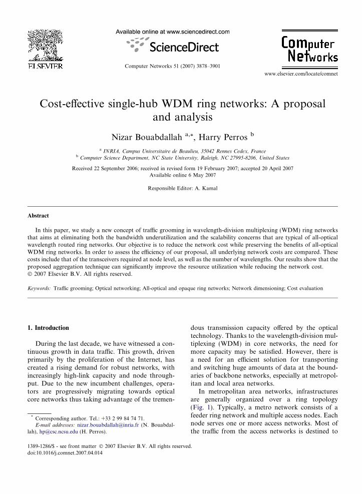
In metropolitan area networks, infrastructuresare generally organized over a ring topology(Fig. 1). Typically, a metro network consists of afeeder ring network and multiple access nodes. Eachnode serves one or more access networks. Most ofthe traffic from the access networks is destined to
.
To/from core network
Ring node
To/from access networks
Hub node
WDM link
Fig. 1. Single-hub WDM ring.
N. Bouabdallah, H. Perros / Computer Networks 51 (2007) 3878–3901 3879
nodes outside of the ring network. Such traffic,carried to the core via the hub node, is calledhubbed traffic. In this paper, we consider hubbedtraffic since it is an important class of traffic and isoften observed in access ring networks.
One of the main issues when designing metronetworks is cost-effectiveness. Minimizing costbecomes the main concern in network design, sincesuch a network handles much smaller group of endusers compared to long-haul networks. For metronetworks, we can save cost in two ways: by sharingbandwidth efficiently and by reducing usage ofexpensive network equipment.
In optical networks, a significant portion of thenetwork cost is due to the equipment used to con-vert signals from the electrical to the opticaldomain. In view of this, the optical layer is migrat-ing from an opaque network, consisting of WDMlinks with electrical processing at the ends of thelink, to an all-optical network, where traffic isswitched at intermediate nodes in the opticaldomain. The optical layer here provides circuitswitched lightpaths to the higher layer equipmentsuch as SONET and IP boxes.
Using optical pass-through instead of electricalprocessing, can lead to an order of magnitude sav-ings in the cost. Nonetheless, the rigid routing gran-ularity entailed by such an approach can lead tobandwidth waste. In order to use the link bandwidthefficiently, we have to allow different access nodes toshare a single wavelength. In addition, routing atthe wavelength level puts a serious strain on thenumber of wavelengths required in the network.For full connectivity, an N node all-optical ring suf-fers from the N-squared problem, since each noderequires N � 1 lightpaths. Even for moderate valuesof N, the total ring capacity is quickly exhausted.
In contrast, an opaque ring has the advantage ofbeing able to use efficiently the link bandwidth.Nonetheless, this results in a maximum transceivercost since nodes do not have an optical bypass. Inthe long term, optical packet switching (OPS)appears as a promising solution. In fact, a majoradvantage of electronic packet switching is its band-width efficiency achieved through statistical multi-plexing. However, OPS is not ready yet and it ishampered by major technology limitations due tothe issues related to the fine switching granularityadopted at high bit rate [1].
To alleviate the aforementioned problems, wepropose a new solution, which combines the advan-tage of the optical bypass in transparent wavelengthrouted networks with statistical multiplexing gain.In this technique, a lightpath, which remainsentirely in the optical domain, is shared by thesource node and all the intermediate nodes up tothe destination. So, in essence, a single lightpath isused to establish a multipoint-to-point (MptoP)connection. We refer to this technique as the distrib-uted aggregation scheme.
To a certain degree, the approach proposed inthis paper can be seen as an extension of an earlierproposal called the Dual Bus Optical Ring Network(DBORN). The DBORN architecture is describedin this paper. For more details please see Ref. [2].
In this study, we provide a typical design of ringnetworks that function according to the distributedaggregation scheme. This new architecture is calledthe MptoP all-optical ring network. Moreover, weassess the cost savings introduced by the MptoParchitecture with respect to DBORN, all-opticaland opaque ring networks. To achieve this, allunderlying network costs are evaluated. These costsinclude that of the transceivers required at the nodelevel and the number of wavelengths. Note that inpractice, the transceiver cost dominates the cost ofthe number of wavelengths in a network.
The rest of the paper is organized as follows. InSection 2 we give a literature review and point outour position relative to previously published papers.A detailed description of this new approach is givenin Section 3. The DBORN architecture and its mainfeatures are given in Section 4. The general problemstatement is presented in Section 5, and in Section 6,all underlying network costs are evaluated. In Sec-tion 7, a cost comparison between our proposaland existing solutions is drawn based on a mathe-matical model. Finally, the conclusions are givenin Section 8.
3880 N. Bouabdallah, H. Perros / Computer Networks 51 (2007) 3878–3901
2. Related work
In optical network literature, several studies dealwith traffic grooming in WDM ring networks [3,4].The trend is towards switching packets directly inthe optical domain, as this can take advantage ofboth packet flexibility and optical transparency.Currently, widely deployed all-optical wavelengthrouted networks are not based on packet switching.However, in the next-generation networks, packet-based data traffic of bursty nature will become pre-valent. Hence, the lack of packet switching in thecurrent optical networks may lead to underutiliza-tion of critical resources. Consequently, two majorenabling factors are identified as crucial for the evo-lution process of next-generation networks architec-ture: packet switching and optical transparency.
Packet switching provides the necessary ingredi-ent needed for building bandwidth efficient and flex-ible networks [1]. Asynchronous transmission,which is more suitable for bursty traffic in compar-ison with slotted WDM networks, must be jointlyaddressed in the future. Moreover, a finer granular-ity than a full wavelength must be achieved whiletrying to preserve the optical transparency propertyin order to avoid extra expensive electronicconversions.
To cope with these requirements, many interest-ing solutions have been proposed in the literature,see [5–12]. These solutions fall into two categories:optical packet switching (OPS) and optical circuitswitching (OCS). In what follows, we review thesenew technologies, pointing out how they reconcileoptical transparency and sub-wavelength groom-ing.
2.1. Optical packet switching-based solutions
A lot of research is currently focusing on how toimplement packet switching in the optical domain.However, OPS is hampered by major technologybottlenecks, such as the lack of optical processinglogic, optical memories, and cost-effective fastswitching and synchronization technologies. Twopromising solutions: have been identified that by-pass some of these technological problems, namely,photonic slot routing (PSR) [5] and optical burstswitching (OBS) [6].
2.1.1. Photonic slot routing
In this technology [5], time is slotted and data istransmitted in the form of photonic slots which are
fixed in time and span across all the wavelengths ofa fiber link. Each wavelength in the photonic slotcontains a single packet and all the packets in thephotonic slot are destined to the same node. Byrequiring the packets to have the same destination,the photonic slot may be routed as a single inte-grated unit without the need for demultiplexingwavelengths at intermediate nodes. The basic aimof such approach is the use of wavelength-insensi-tive components at each node, resulting in less com-plexity, faster routing and lower cost with regard toclassical OPS concept.
As such, the PSR approach relieves some typicalissues of OPS. But, it still requires high-speed con-figurable optical packet switches, where the dataprocessing and switching is done on a slot basis.In addition, the implementation of PSR in a meshenvironment is an even more challenging key issue,as it involves maintaining the synchronization ofphotonic slots at each node.
2.1.2. Optical burst switching
Optical burst switching (OBS) [6] avoids the veryshort switching time required by OPS. A burst is anaggregation of many packets with the same egressnode, and the same class of service. Using largebursts of data, the processing on the network canbe reduced compared to OPS. Optical burst switch-ing can be considered therefore as a hybridapproach between coarse-grained circuit switchingand fine-grained packet switching. The bursts areaggregated by edge nodes and transmitted all-opti-cally towards their destination. Each burst is pre-ceded in time (offset time) by a control packetwhich is used to reserve resources at each switchin the core network. The offset time must be largeenough so that each switch has the time to config-ure its switch fabric prior to the arrival of theburst.
In this regard, compared to the wavelength rou-ted switches (i.e., OCS), the OBS edge routers needcomplex interfaces to implement burst assembly,disassembly, and queue fairness algorithms. Thus,the access unit design may become challenging athigh data rates. Furthermore, in OBS, there is noguarantee that a burst will be successfully transmit-ted without being dropped by intermediate nodesdue to contention of bursts going to the same outgo-ing port. Depending upon the nature of thetransmitted data, a dropped burst may have to beretransmitted, which of course decreases thenetwork’s throughput.
N. Bouabdallah, H. Perros / Computer Networks 51 (2007) 3878–3901 3881
2.2. Optical circuit switched-based solutions
OPS, and in particular PSR, is a solution thatmay become feasible in the future. Meanwhile, thetrend is to improve the efficiency of existing matureall-optical networks. In this regard, recently, therehas been much emphasis on circuit switched all-optical networks, where the goal in this context isshifted more toward the improvement of opticalresource usage by means of new traffic aggregationschemes, rather than toward the attempt to realizeoptical packet switching.
2.2.1. The multi-hop approach
The key idea behind multi-hop (MH) networks isto allow electronic processing at some intermediatenodes of the all-optical circuit switched network inorder to increase its grooming capacity [7]. Accord-ingly, a packet may undergo electronic processing atsome intermediate nodes before reaching its finaldestination. Hence, lightpaths can be seen as chainsof physical channels through which packets aremoved from a router to another toward their desti-nations. At intermediate nodes, the transit light-paths are switched transparently through an OXCthat does not process transit data. Instead, incominglightpaths destined to the current node are termi-nated and converted to the electronic domain, sothat packets can be extracted, processed, and possi-bly retransmitted on outgoing lightpaths, if the cur-rent node is not the final destination of the data.
Although the significant cost that may be intro-duced by such electronic processing operation atintermediate nodes, it enables a better use of the net-work resources and can reduce the total networkcost compared to the all-optical circuit switched net-works [7]. The main challenge, in this case, is toidentify the optimal logical topology that minimizesthe total network cost, while accommodating all thetraffic requests. It has been demonstrated that theidentification of the optimal logical topology iscomputationally intractable for large size networks[13]. In view of this, several heuristic approacheswere proposed in literature [7].
2.2.2. The super-lightpath and lightpath dropping
approaches
The super-lightpath concept [8] and the lightpathdropping [9] approach increase the grooming capac-ity of a regular all-optical circuit switched network,as they transform the concept of the lightpath froma point-to-point (PtoP) pipe to a point-to-multi-
point (PtoMP) pipe. In other words, the sourcenode of a super-lightpath or a multiply dropped-lightpath does not limit its transmission to the endnod node of that lightpath; instead, it can transmitits traffic to all the intermediate nodes along theroute. This allows the super-lightpath or the multi-ply dropped-lightpath to carry multiple connec-tions, resulting in better wavelength utilization.
The super-lightpath technique uses a simple Opti-cal Time Division Multiplexing (OTDM) method,which permits splitting the bandwidth of a wave-length among several traffic flows. Accordingly,each bit in a given position of the fixed-size TDMframe, called bit slot, identifies a particular sub-channel. Using a bit interleaver, the transmittermultiplexes sub-channels into the frame, and trans-mits the resulting stream into one lightpath. Withregard to reception, each intermediate node splitsthe transit signal, synchronizes its receiver to a par-ticular bit slot, and only receives data in that partic-ular sub-channel.
The super-lightpath and the lightpath droppingtechniques present many advantages. First, theyreduce the number of transmitters per node sincethe same transmitter will be used to send data tomore than one receiver. Moreover, they improvethe lightpath utilization. Specifically, in [9], theauthors show that the lightpath dropping approachleads to better performance in terms of blockingprobability when compared to the MH approach[7]. The main concern with these PtoMP methodsis related to the limited length of the super-lightpathor dropped-lightpath. Specifically, a significant por-tion of the passing-through optical signal is tappedat each receiving intermediate node, and therefore,due to power limitations the number of traversednodes is limited.
2.2.3. The TWIN (time-domain wavelength
interleaved networking) approach
Unlike the super-lightpath concept, which uses aPtoMP approach to improve the traffic groomingcapacity in a traditional OCS network, the TWINtechnique adopts a MptoP approach [10]. Specifi-cally, TWIN makes use of optical MptoP trees thatare overlaid on the top of the physical topology. InTWIN, a particular wavelength is attributed to eachegress node, and it is used to receive data. Doing so,sources that have information to transmit to a par-ticular destination, tune their transmitters to theparticular wavelength. As such, the optical signalsfrom various sources to a particular destination
3882 N. Bouabdallah, H. Perros / Computer Networks 51 (2007) 3878–3901
may be merged at the intermediate nodes. Thus,TWIN technology requires special OXCs, whichare able to merge incoming signals of the samewavelength to the same outgoing wavelength.
Despite the complex scheduling algorithmsentailed by such an approach, the MptoP conceptis in itself interesting. It avoids the limitations onthe length of a super-lightpath introduced by thePtoMP approach, since no splitting operations areperformed.
Nevertheless, the MptoP concept as described inTWIN suffers from scalability issues. The assign-ment of multiple wavelengths to each egress node(according to the volume of its destined traffic)makes a serious stress on the number of wavelengthchannels required on each fiber link. Moreover,TWIN may lead to fiber link underutilization dueto the lack of wavelength reuse, since a particularwavelength, wherever the link that belongs to, canonly be used to transmit to a specific egress node.
2.2.4. The optical light-trails approach
The light-trail (LT) is an OCS-based technologythat minimizes active switching, maximizes wave-lengths utilization, and offers protocol and bit ratetransparency [11,12]. So far, we have presented aPtoP approach (i.e., MH), a PtoMP approach(i.e., super-lightpath) and a MptoP approach (i.e.,TWIN), which aim at achieving these goals. TheLT solution is a MPtoMP approach where interme-diate nodes can both receive and transmit data onthe pass-through channel.
The basic operation of this scheme is as follows.Each intermediate node i of the LT taps a sufficientamount of optical power from the incoming signal,using a splitter, in order to recover its correspondingpackets sent by the upstream nodes. On the otherside, with regard to transmission, the original transitsignal is coupled with the local signal, by means of acoupler, before it continues its path to serve theremaining downstream nodes of the LT.
The main concern with this method is the designof a MAC protocol that avoids collisions betweentransit and locally inserted packets. A simpleMAC protocol based on intra-band signaling wassuggested in the original LT proposal [11]. Accord-ingly, each intermediate node i, wishing to transmita packet, first sends a beacon signal to order down-stream nodes to stop their activities on the sharedmedium. Then, after a guard band, it transmits itsdata packet. Note that, node i may receive a beaconsignal from upstream nodes during its transmission
of a beacon signal or a data packet. In this case, itpreempts instantaneously its transmission and thetruncated packet is lost.
Due to the above scheme, the performance of theLT method is questionable. This is because, such aMAC scheme may result in low resource utilizationdue to the guard band, extra signaling packets andwasted truncated packets. In this regard, many stud-ies are now focusing in the development of moreefficient MAC schemes adapted to the LT technol-ogy [14]. Also, additional protocols are required toavoid fairness issues among the sharing LT nodes[15]. Furthermore, since a significant portion ofthe signal is tapped at each intermediate node, theLT length may be limited. This limitation, however,can be overcome using a power compensator, suchas a semiconductor optical amplifier (SOA). Finally,we note that packets received by an intermediatenode are not removed from the LT, which preventsbandwidth reutilization by downstream nodes. Thisfeature becomes interesting only when dealing withmulticast applications.
As explained before, methods based on multiplenode reception, such as super-lightpath and LT,suffer from power limitations due to the requiredmultiple splittings. Moreover, the multiple nodesreception feature in LT, is effective only when deal-ing with multicast applications due to the lack ofbandwidth reutilization of the shared lightpath. Inview of this, the MptoP strategy appears as the bestchoice to improve the grooming capacity of a light-path. In this context, TWIN technology is a goodcandidate. However, this technique suffers frominherent scalability and lack of wavelength reuse.In order to ameliorate this situation, we proposea new MptoP OCS-based solution, called thedistributed aggregation scheme.
3. Distributed aggregation scheme
The key idea underlying our proposed scheme isto allow sharing of a lightpath among several accessnodes. Instead of limiting the access to the lightpathcapacity at the ingress point, each node along thepath can fill the lightpath on the fly according toits availability. In this case, a lightpath can beshared by multiple connections with a common des-tination (i.e., MptoP lightpaths). Wavelength rout-ing is performed in a similar way as in all-opticalnetworks, i.e., signals remain in the optical domainfrom end to end and are optically switched byintermediate nodes. Since the lightpath remains
N. Bouabdallah, H. Perros / Computer Networks 51 (2007) 3878–3901 3883
transparent at intermediate nodes, a MAC (Med-ium Access Control) protocol is required to avoidcollision between transient optical packets and localones injected into the lightpath. In [16], we havealready proposed a simple MAC protocol basedon void/null detection. This mechanism, describedbelow, guarantees collision-free packet insertionon the transient wavelength at the add port levelof an intermediate node.
3.1. The distributed aggregation scheme: an example
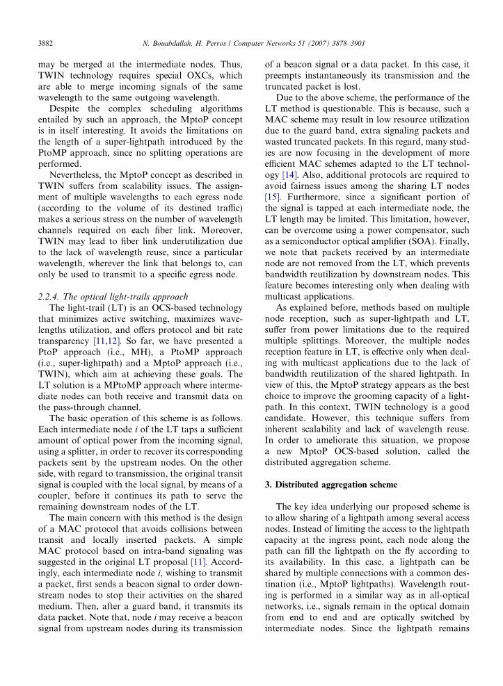
To illustrate the distributed aggregation mecha-nism, we consider the simple three-node networkexample shown in Fig. 2. We assume that each fiberhas one wavelength and each node is equipped witha fixed transmitter and a fixed receiver. Two connec-tion requests are to be served: (0, 2) with a band-width requirement equal to half of the wavelengthcapacity; and (1,2) with a bandwidth requirementequal to quarter of the wavelength capacity.
In the classical wavelength routed all-optical net-work case (Fig. 2a), only the connection (0,2) willbe served. The connection (1, 2) between nodes 1and 2 will be rejected even if the wavelength betweenthese two nodes is not being fully used by the (0,2)connection. Hence, an extra wavelength betweennodes 1 and 2, and a new receiver at node 2 arerequired in order to satisfy the two connectionrequests.
In the case of the distributed aggregation scheme(Fig. 2b), the traffic demand could be satisfied byestablishing one lightpath from node 0 to node 2,which will be shared by both connections. The sec-ond connection (1, 2) would be carried using thespare capacity of the existing lightpath. Note thatthe lightpath 0! 1! 2 is still routed opticallythrough node 1, thus preserving the benefit of opti-cal bypass.
The merit of distributed aggregation is that mul-tiple connections with fractional demands can be
Demand matrix :
Connection 1 : 0 Connection 2 : 1-Unit : wavelength ch
Receiver Transmitter
Lightpath (0,2)
1
0 2
aFig. 2. A simple demonstration network. (a) All-optical wavelengt(b) Distributed aggregation scheme. All connection requests are satisfie
multiplexed onto the same lightpath. As a result,the wasted bandwidth problem associated withpure wavelength routed networks is alleviated. Inaddition, due to the sharing of lightpaths, the num-ber of admissible connections in the network isincreased. Furthermore, the destination node han-dles fewer lightpaths as connections from differentnodes to the same destination are aggregated ontothe same lightpath. In view of this, fewer physicalcomponents, such as wavelengths and transceivers,are used, resulting in savings on equipment. More-over, in order to provide connections between allaccess node pairs using MptoP lightpaths, a totalnumber of O(N) lightpaths is required since onlyone lightpath per individual egress node could besufficient. Thus, we alleviate the scalability issueencountered in classical all-optical wavelengthrouted networks.
3.2. The MptoP ring network architecture
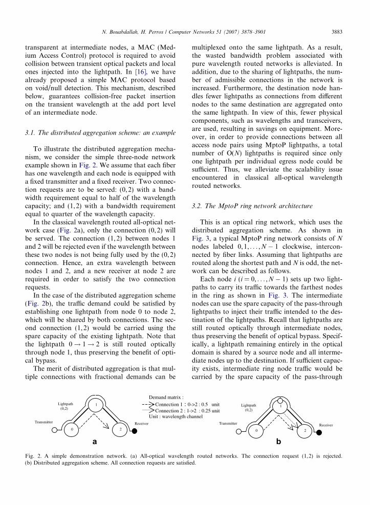
This is an optical ring network, which uses thedistributed aggregation scheme. As shown inFig. 3, a typical MptoP ring network consists of N
nodes labeled 0,1, . . . ,N � 1 clockwise, intercon-nected by fiber links. Assuming that lightpaths arerouted along the shortest path and N is odd, the net-work can be described as follows.
Each node i (i = 0, . . . ,N � 1) sets up two light-paths to carry its traffic towards the farthest nodesin the ring as shown in Fig. 3. The intermediatenodes can use the spare capacity of the pass-throughlightpaths to inject their traffic intended to the des-tination of the lightpaths. Recall that lightpaths arestill routed optically through intermediate nodes,thus preserving the benefit of optical bypass. Specif-ically, a lightpath remaining entirely in the opticaldomain is shared by a source node and all interme-diate nodes up to the destination. If sufficient capac-ity exists, intermediate ring node traffic would becarried by the spare capacity of the pass-through
->2 : 0.5 unit >2 : 0.25 unit annel
Receiver Transmitter
Lightpath (0,2)
1
0 2
bh routed networks. The connection request (1,2) is rejected.d.
To/from core network
Ring node 1
Hub node (# 0)
Ring node N-1
Ring node i
Destnationnodes
MptoPlightpath
Fig. 3. MptoP WDM ring: lightpaths initiated by node i.
3884 N. Bouabdallah, H. Perros / Computer Networks 51 (2007) 3878–3901
lightpaths. Otherwise, the intermediate ring nodehas to create new lightpaths to handle the remaininglocal traffic destined to the destination node of thepass-through lightpath (see Fig. 3: case of ringnode 1).
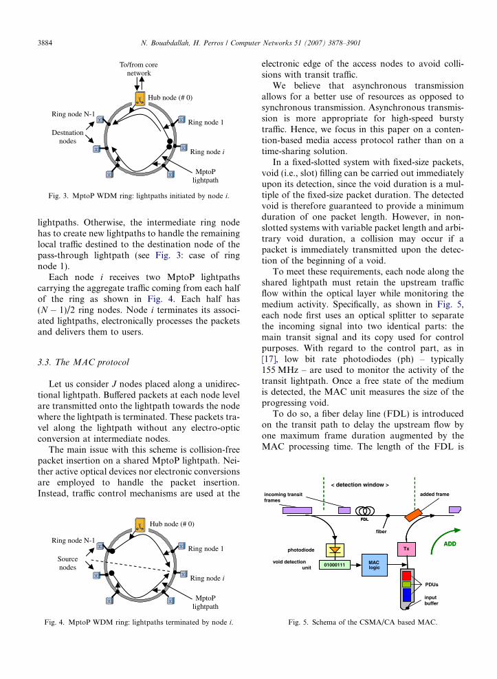
Each node i receives two MptoP lightpathscarrying the aggregate traffic coming from each halfof the ring as shown in Fig. 4. Each half has(N � 1)/2 ring nodes. Node i terminates its associ-ated lightpaths, electronically processes the packetsand delivers them to users.
< detection window >
incoming transit added frame
3.3. The MAC protocol
Let us consider J nodes placed along a unidirec-tional lightpath. Buffered packets at each node levelare transmitted onto the lightpath towards the nodewhere the lightpath is terminated. These packets tra-vel along the lightpath without any electro-opticconversion at intermediate nodes.
The main issue with this scheme is collision-freepacket insertion on a shared MptoP lightpath. Nei-ther active optical devices nor electronic conversionsare employed to handle the packet insertion.Instead, traffic control mechanisms are used at the
Ring node 1
Hub node (# 0)
Ring node N-1
Ring node i
Sourcenodes
MptoPlightpath
Fig. 4. MptoP WDM ring: lightpaths terminated by node i.
electronic edge of the access nodes to avoid colli-sions with transit traffic.
We believe that asynchronous transmissionallows for a better use of resources as opposed tosynchronous transmission. Asynchronous transmis-sion is more appropriate for high-speed burstytraffic. Hence, we focus in this paper on a conten-tion-based media access protocol rather than on atime-sharing solution.
In a fixed-slotted system with fixed-size packets,void (i.e., slot) filling can be carried out immediatelyupon its detection, since the void duration is a mul-tiple of the fixed-size packet duration. The detectedvoid is therefore guaranteed to provide a minimumduration of one packet length. However, in non-slotted systems with variable packet length and arbi-trary void duration, a collision may occur if apacket is immediately transmitted upon the detec-tion of the beginning of a void.
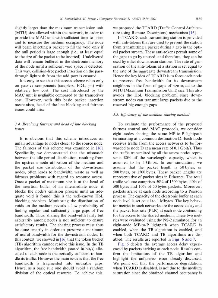
To meet these requirements, each node along theshared lightpath must retain the upstream trafficflow within the optical layer while monitoring themedium activity. Specifically, as shown in Fig. 5,each node first uses an optical splitter to separatethe incoming signal into two identical parts: themain transit signal and its copy used for controlpurposes. With regard to the control part, as in[17], low bit rate photodiodes (ph) – typically155 MHz – are used to monitor the activity of thetransit lightpath. Once a free state of the mediumis detected, the MAC unit measures the size of theprogressing void.
To do so, a fiber delay line (FDL) is introducedon the transit path to delay the upstream flow byone maximum frame duration augmented by theMAC processing time. The length of the FDL is
FDL
inputbuffer
PDUs
ADDphotodiode
fiber
01000111void detection
unit
frames
Tx
MAClogic
FDL
ADD
01000111
Tx
MAClogic
Fig. 5. Schema of the CSMA/CA based MAC.
N. Bouabdallah, H. Perros / Computer Networks 51 (2007) 3878–3901 3885
slightly larger than the maximum transmission unit(MTU) size allowed within the network, in order toprovide the MAC unit with sufficient time to listenand to measure the medium occupancy. The nodewill begin injecting a packet to fill the void only ifthe null period is large enough (i.e., at least equalto the size of the packet to be inserted). Undelivereddata will remain buffered in the electronic memoryof the node until a sufficient void space is detected.This way, collision-free packet insertion on the pass-through lightpath from the add port is ensured.
It is easy to see that this access scheme relies onlyon passive components (couplers, FDL, ph) withrelatively low cost. The cost introduced by theMAC unit is negligible compared to the transceivercost. However, with this basic packet insertionmechanism, head of the line blocking and fairnessissues could arise.
3.4. Resolving fairness and head of line blocking
issues
It is obvious that this scheme introduces anunfair advantage to nodes closer to the source node.The fairness of this scheme was examined in [16].Specifically, we demonstrated that the mismatchbetween the idle period distribution, resulting fromthe upstream node utilization of the medium andthe packet size distribution of the downstreamnodes, often leads to bandwidth waste as well asfairness problems with regard to resource access.Once a packet of maximum size is at the head ofthe insertion buffer of an intermediate node, itblocks the node’s emission process until an ade-quate void is found: this is the well-known HoLblocking problem. Monitoring the distribution ofvoids on the medium reveals a low probability offinding regular and sufficiently large gaps of freebandwidth. Thus, sharing the bandwidth fairly butarbitrarily among nodes is not sufficient to ensuresatisfactory results. The sharing process must thusbe done smartly in order to preserve a maximumof useful bandwidth for the downstream nodes. Inthis context, we showed in [16] that the token bucket(TB) algorithm cannot resolve this issue. In the TBalgorithm, the free bandwidth (stated in bit/s) allo-cated to each node is theoretically sufficient to han-dle its traffic. However the main issue is that the freebandwidth is fragmented into unusable gaps.Hence, as a basic rule one should avoid a randomdivision of the optical resource. To achieve this,
we proposed the TCARD (Traffic Control Architec-ture using Remote Descriptors) mechanism [16].
In TCARD, each transmitting station is providedwith anti-tokens that are used to prevent the stationfrom transmitting a packet during a gap in the opti-cal packet stream. These anti-tokens permit some ofthe gaps to go by unused, and therefore, they can beused by other downstream stations. The rate of gen-eration of the anti-tokens at a station is set equal tothe rate of the aggregate downstream transmission.Hence the key idea of TCARD is to force each nodeto preserve free bandwidth for its downstreamneighbors in the form of gaps of size equal to theMTU (Maximum Transmission Unit) size. This alsoavoids the HoL blocking problem, since down-stream nodes can transmit large packets due to thereserved big-enough gaps.
3.5. Efficiency of the medium sharing method
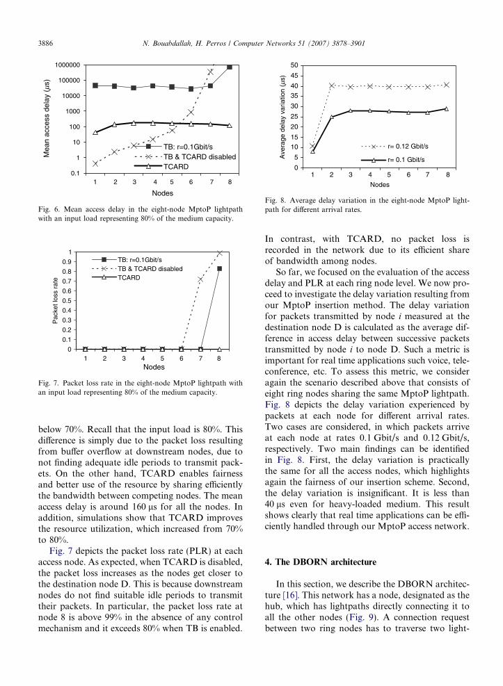
To evaluate the performance of the proposedfairness control and MAC protocols, we considereight nodes sharing the same MP-to-P lightpathterminating at a common destination D. Each nodereceives traffic from the access networks to be for-warded to node D at a mean rate of 0.1 Gbit/s. Thusthe traffic transmitted by all the access nodes repre-sents 80% of the wavelength capacity, which isassumed to be 1 Gbit/s. In our simulation, weassume that the packet length is 50 bytes, or500 bytes, or 1500 bytes. These packet lengths arerepresentative of packet sizes in Ethernet. The totaltraffic volume comprises 50% of 1500 bytes, 40% of500 bytes and 10% of 50 bytes packets. Moreover,packets arrive at each node according to a Poissonprocess. The capacity of the electronic buffer at eachnode level is set equal to 1 Mbytes. The key behav-ior metrics in such networks are the access delay andthe packet loss rate (PLR) at each node contendingfor the access to the shared medium. These two met-rics were evaluated using the NS-2 simulator, for aneight-node MP-to-P lightpath when TCARD isenabled, when the TB algorithm is enabled, andwhen both TCARD and TB algorithms are dis-abled. The results are reported in Figs. 6 and 7.
Fig. 6 depicts the average access delay experi-enced by packets arriving at each node. Results con-firm the limitations of the TB algorithm andhighlight the unfairness issue already discussed.We point out that the performance degradation,when TCARD is disabled, is not due to the mediumsaturation since the obtained channel occupancy is
0.1
1
10
100
1000
10000
100000
1000000
1 2 3 4 5 6 7 8
Nodes
Mea
n ac
cess
del
ay (
ms)
TB: r=0.1Gbit/sTB & TCARD disabledTCARD
Fig. 6. Mean access delay in the eight-node MptoP lightpathwith an input load representing 80% of the medium capacity.
1 2 3 4 5 6 7 8Nodes
Pac
ket l
oss
rate
TB: r=0.1Gbit/sTB & TCARD disabledTCARD
1
0.9
0.8
0.7
0.6
0.5
0.4
0.3
0.2
0.1
0
Fig. 7. Packet loss rate in the eight-node MptoP lightpath withan input load representing 80% of the medium capacity.
0
5
10
15
20
25
30
35
40
45
50
1 2 3 4 5 6 7 8
Nodes
Ave
rage
del
ay v
aria
tion
(ms)
r= 0.12 Gbit/s
r= 0.1 Gbit/s
Fig. 8. Average delay variation in the eight-node MptoP light-path for different arrival rates.
3886 N. Bouabdallah, H. Perros / Computer Networks 51 (2007) 3878–3901
below 70%. Recall that the input load is 80%. Thisdifference is simply due to the packet loss resultingfrom buffer overflow at downstream nodes, due tonot finding adequate idle periods to transmit pack-ets. On the other hand, TCARD enables fairnessand better use of the resource by sharing efficientlythe bandwidth between competing nodes. The meanaccess delay is around 160 ls for all the nodes. Inaddition, simulations show that TCARD improvesthe resource utilization, which increased from 70%to 80%.
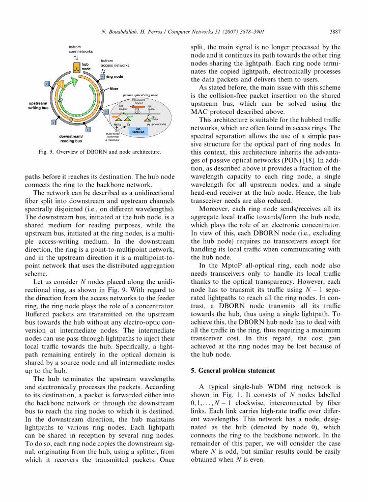
Fig. 7 depicts the packet loss rate (PLR) at eachaccess node. As expected, when TCARD is disabled,the packet loss increases as the nodes get closer tothe destination node D. This is because downstreamnodes do not find suitable idle periods to transmittheir packets. In particular, the packet loss rate atnode 8 is above 99% in the absence of any controlmechanism and it exceeds 80% when TB is enabled.
In contrast, with TCARD, no packet loss isrecorded in the network due to its efficient shareof bandwidth among nodes.
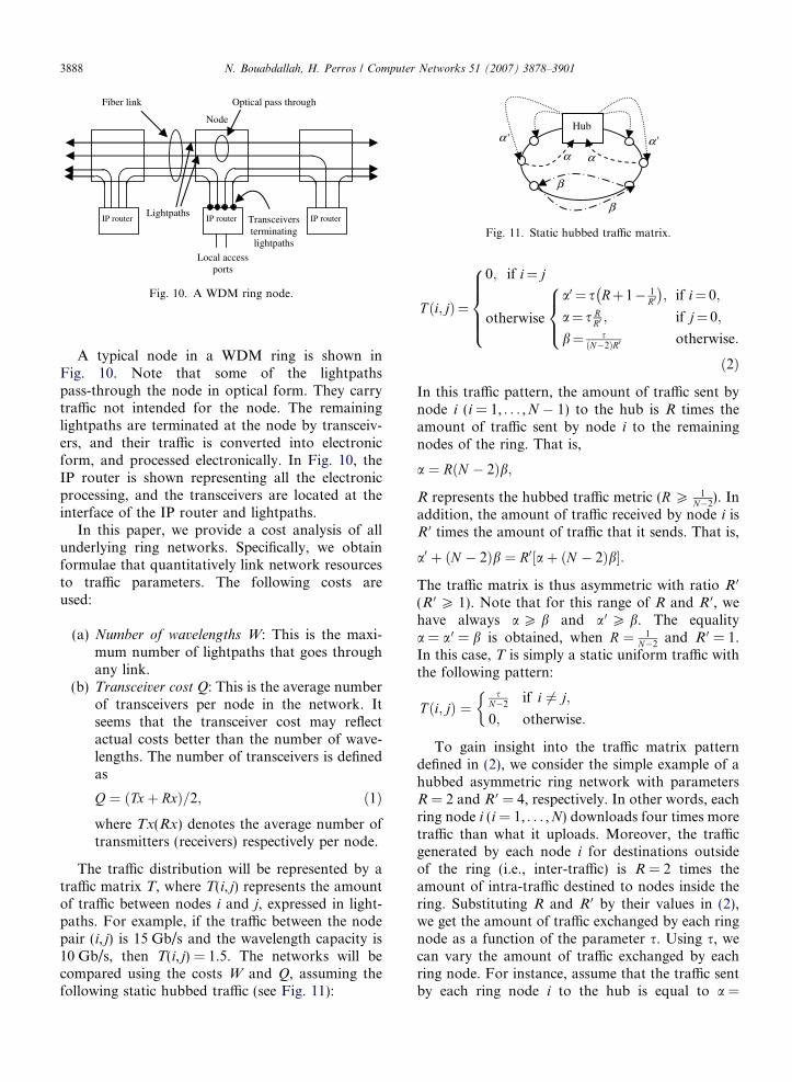
So far, we focused on the evaluation of the accessdelay and PLR at each ring node level. We now pro-ceed to investigate the delay variation resulting fromour MptoP insertion method. The delay variationfor packets transmitted by node i measured at thedestination node D is calculated as the average dif-ference in access delay between successive packetstransmitted by node i to node D. Such a metric isimportant for real time applications such voice, tele-conference, etc. To assess this metric, we consideragain the scenario described above that consists ofeight ring nodes sharing the same MptoP lightpath.Fig. 8 depicts the delay variation experienced bypackets at each node for different arrival rates.Two cases are considered, in which packets arriveat each node at rates 0.1 Gbit/s and 0.12 Gbit/s,respectively. Two main findings can be identifiedin Fig. 8. First, the delay variation is practicallythe same for all the access nodes, which highlightsagain the fairness of our insertion scheme. Second,the delay variation is insignificant. It is less than40 ls even for heavy-loaded medium. This resultshows clearly that real time applications can be effi-ciently handled through our MptoP access network.
4. The DBORN architecture
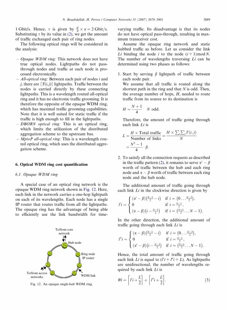
In this section, we describe the DBORN architec-ture [16]. This network has a node, designated as thehub, which has lightpaths directly connecting it toall the other nodes (Fig. 9). A connection requestbetween two ring nodes has to traverse two light-
hubnode
ring node
fiber
downstream/ reading bus
upstream/writing bus .
l
t u
drop
passive optical ring node
to/fromcore networks
to/fromaccess networks
Fig. 9. Overview of DBORN and node architecture.
N. Bouabdallah, H. Perros / Computer Networks 51 (2007) 3878–3901 3887
paths before it reaches its destination. The hub nodeconnects the ring to the backbone network.
The network can be described as a unidirectionalfiber split into downstream and upstream channelsspectrally disjointed (i.e., on different wavelengths).The downstream bus, initiated at the hub node, is ashared medium for reading purposes, while theupstream bus, initiated at the ring nodes, is a multi-ple access-writing medium. In the downstreamdirection, the ring is a point-to-multipoint network,and in the upstream direction it is a multipoint-to-point network that uses the distributed aggregationscheme.
Let us consider N nodes placed along the unidi-rectional ring, as shown in Fig. 9. With regard tothe direction from the access networks to the feederring, the ring node plays the role of a concentrator.Buffered packets are transmitted on the upstreambus towards the hub without any electro-optic con-version at intermediate nodes. The intermediatenodes can use pass-through lightpaths to inject theirlocal traffic towards the hub. Specifically, a light-path remaining entirely in the optical domain isshared by a source node and all intermediate nodesup to the hub.
The hub terminates the upstream wavelengthsand electronically processes the packets. Accordingto its destination, a packet is forwarded either intothe backbone network or through the downstreambus to reach the ring nodes to which it is destined.In the downstream direction, the hub maintainslightpaths to various ring nodes. Each lightpathcan be shared in reception by several ring nodes.To do so, each ring node copies the downstream sig-nal, originating from the hub, using a splitter, fromwhich it recovers the transmitted packets. Once
split, the main signal is no longer processed by thenode and it continues its path towards the other ringnodes sharing the lightpath. Each ring node termi-nates the copied lightpath, electronically processesthe data packets and delivers them to users.
As stated before, the main issue with this schemeis the collision-free packet insertion on the sharedupstream bus, which can be solved using theMAC protocol described above.
This architecture is suitable for the hubbed trafficnetworks, which are often found in access rings. Thespectral separation allows the use of a simple pas-sive structure for the optical part of ring nodes. Inthis context, this architecture inherits the advanta-ges of passive optical networks (PON) [18]. In addi-tion, as described above it provides a fraction of thewavelength capacity to each ring node, a singlewavelength for all upstream nodes, and a singlehead-end receiver at the hub node. Hence, the hubtransceiver needs are also reduced.
Moreover, each ring node sends/receives all itsaggregate local traffic towards/form the hub node,which plays the role of an electronic concentrator.In view of this, each DBORN node (i.e., excludingthe hub node) requires no transceivers except forhandling its local traffic when communicating withthe hub node.
In the MptoP all-optical ring, each node alsoneeds transceivers only to handle its local trafficthanks to the optical transparency. However, eachnode has to transmit its traffic using N � 1 sepa-rated lightpaths to reach all the ring nodes. In con-trast, a DBORN node transmits all its traffictowards the hub, thus using a single lightpath. Toachieve this, the DBORN hub node has to deal withall the traffic in the ring, thus requiring a maximumtransceiver cost. In this regard, the cost gainachieved at the ring nodes may be lost because ofthe hub node.
5. General problem statement
A typical single-hub WDM ring network isshown in Fig. 1. It consists of N nodes labelled0,1, . . . ,N � 1 clockwise, interconnected by fiberlinks. Each link carries high-rate traffic over differ-ent wavelengths. This network has a node, desig-nated as the hub (denoted by node 0), whichconnects the ring to the backbone network. In theremainder of this paper, we will consider the casewhere N is odd, but similar results could be easilyobtained when N is even.
IP router IP router IP router
Fiber link
Lightpaths
Optical pass through
Transceiversterminating lightpaths
Node
Local access ports
Fig. 10. A WDM ring node.
Hub
α α
'α 'α
β
β
Fig. 11. Static hubbed traffic matrix.
3888 N. Bouabdallah, H. Perros / Computer Networks 51 (2007) 3878–3901
A typical node in a WDM ring is shown inFig. 10. Note that some of the lightpathspass-through the node in optical form. They carrytraffic not intended for the node. The remaininglightpaths are terminated at the node by transceiv-ers, and their traffic is converted into electronicform, and processed electronically. In Fig. 10, theIP router is shown representing all the electronicprocessing, and the transceivers are located at theinterface of the IP router and lightpaths.
In this paper, we provide a cost analysis of allunderlying ring networks. Specifically, we obtainformulae that quantitatively link network resourcesto traffic parameters. The following costs areused:
(a) Number of wavelengths W: This is the maxi-mum number of lightpaths that goes throughany link.
(b) Transceiver cost Q: This is the average numberof transceivers per node in the network. Itseems that the transceiver cost may reflectactual costs better than the number of wave-lengths. The number of transceivers is definedas
Q ¼ ðTxþ RxÞ=2; ð1Þ
where Tx(Rx) denotes the average number oftransmitters (receivers) respectively per node.The traffic distribution will be represented by atraffic matrix T, where T(i, j) represents the amountof traffic between nodes i and j, expressed in light-paths. For example, if the traffic between the nodepair (i, j) is 15 Gb/s and the wavelength capacity is10 Gb/s, then T(i, j) = 1.5. The networks will becompared using the costs W and Q, assuming thefollowing static hubbed traffic (see Fig. 11):
T ði;jÞ¼
0; if i¼ j
otherwise
a0 ¼ s Rþ1� 1R0
� �; if i¼ 0;
a¼ s RR0 ; if j¼ 0;
b¼ sðN�2ÞR0 otherwise:
8><>:
8>>><>>>:
ð2Þ
In this traffic pattern, the amount of traffic sent bynode i (i = 1, . . . ,N � 1) to the hub is R times theamount of traffic sent by node i to the remainingnodes of the ring. That is,
a ¼ RðN � 2Þb;
R represents the hubbed traffic metric (R P 1N�2
). Inaddition, the amount of traffic received by node i isR 0 times the amount of traffic that it sends. That is,
a0 þ ðN � 2Þb ¼ R0½aþ ðN � 2Þb�:
The traffic matrix is thus asymmetric with ratio R 0
(R 0 P 1). Note that for this range of R and R 0, wehave always a P b and a 0 P b. The equalitya = a 0 = b is obtained, when R ¼ 1
N�2and R 0 = 1.
In this case, T is simply a static uniform traffic withthe following pattern:
T ði; jÞ ¼s
N�2if i 6¼ j;
0; otherwise:
�
To gain insight into the traffic matrix patterndefined in (2), we consider the simple example of ahubbed asymmetric ring network with parametersR = 2 and R 0 = 4, respectively. In other words, eachring node i (i = 1, . . . ,N) downloads four times moretraffic than what it uploads. Moreover, the trafficgenerated by each node i for destinations outsideof the ring (i.e., inter-traffic) is R = 2 times theamount of intra-traffic destined to nodes inside thering. Substituting R and R 0 by their values in (2),we get the amount of traffic exchanged by each ringnode as a function of the parameter s. Using s, wecan vary the amount of traffic exchanged by eachring node. For instance, assume that the traffic sentby each ring node i to the hub is equal to a =
N. Bouabdallah, H. Perros / Computer Networks 51 (2007) 3878–3901 3889
1 Gbit/s. Hence, s is given by R0
R � a ¼ 2 Gbit=s.Substituting s by its value in (2), we get the amountof traffic exchanged each pair of ring nodes.
The following optical rings will be considered inthe analysis:
– Opaque WDM ring: This network does not havetrue optical nodes. Lightpaths do not pass-through nodes and traffic at each node is pro-cessed electronically.
– All-optical ring: Between each pair of nodes i andj, there are dT(i, j)e lightpaths. Traffic between thenodes is carried directly by these connectinglightpaths. This is a wavelength routed all-opticalring and it has no electronic traffic grooming. It istherefore the opposite of the opaque WDM ring,which has maximal traffic grooming capabilities.Note that it is well suited for static traffic if thetraffic is high enough to fill in the lightpaths.
– DBORN optical ring: This is an optical ring,which limits the utilization of the distributedaggregation scheme to the upstream bus.
– MptoP all-optical ring: This is a wavelength rou-ted optical ring, which uses the distributed aggre-gation scheme.
6. Optical WDM ring cost quantification
6.1. Opaque WDM ring
A special case of an optical ring network is theopaque WDM ring network shown in Fig. 12. Here,each link in the network carries a one-hop lightpathon each of its wavelengths. Each node has a singleIP router that routes traffic from all the lightpaths.The opaque ring has the advantage of being ableto efficiently use the link bandwidth for time-
To/from core network
Ring node IP router
To/from access networks
Hub node
WDM link
Fig. 12. An opaque single-hub WDM ring.
varying traffic. Its disadvantage is that its nodesdo not have optical pass-through, resulting in max-imum transceiver cost.
Assume the opaque ring network and statichubbed traffic as before. Let us consider the linkLi binding the node i to the node (i + 1)mod N.The number of wavelengths traversing Li can bedetermined using two phases as follows:
1. Start by serving b lightpath of traffic betweeneach node pair.We assume that all traffic is routed along theshortest path in the ring and that N is odd. Then,the average number of hops, H, needed to routetraffic from its source to its destination is
H ¼ N þ 1
4N odd:
Therefore, the amount of traffic going througheach link Li is
L ¼ H � Total traffic
Number of links¼
H �P
i
PjT ði; jÞ
N
¼ N 2 � 1
4� b:
2. To satisfy all the connection requests as describedin the traffic pattern (2), it remains to serve a 0 � bworth of traffic between the hub and each ringnode and a � b worth of traffic between each ringnode and the hub node.
The additional amount of traffic going througheach link Li in the clockwise direction is given by
l0i ¼ða0 � bÞ N�1
2� i
� �if i ¼ 0 . . . N�3
2
� �;
0 if i ¼ N�12;
ða� bÞ i� N�12
� �if i ¼ Nþ1
2. . . N � 1
� �:
8><>:
In the other direction, the additional amount oftraffic going through each link Li is
l00i ¼ða� bÞ N�1
2� i
� �if i ¼ 0 . . . N�3
2
� �;
0 if i ¼ N�12;
ða0 � bÞ i� N�12
� �if i ¼ Nþ1
2. . . N � 1
� �:
8><>:
Hence, the total amount of traffic going througheach link Li is equal to (l 0i + l00i + L). As lightpathsare unidirectional, the number of wavelengths re-quired by each link Li is
Wi ¼ l0iþ L2
� �þ l00iþ L
2
� �: ð3Þ
Hub
Link L0 : additional wavelengths
βαα )1(' −++ K
The two new nodes divide the ring into two parts. Old node
[ [[ [
Fig. 14. Setting up lightpaths for two new nodes (Step k).
3890 N. Bouabdallah, H. Perros / Computer Networks 51 (2007) 3878–3901
It is easy to see that both L0 and LN � 1 are themost loaded links, since a P b and a 0 P b. Thusthe number of wavelength is simply:
W ¼ W 0 ¼ WN � 1: ð4ÞAlso recall that the number of transceivers per nodeis
Q½i� ¼ Tx½i� ¼ Rx½i� ¼ Wi2þ W ði� 1ÞmodN
2: ð5Þ
The average number of transceiver per node istherefore:
Q ¼PN�1
i¼0 WiN
: ð6Þ
6.2. All-optical ring
In this network dT(i, j)e lightpaths have to be setup between each source and destination nodes. Thistype of network has been considered in [19], butassuming full duplex lightpaths and static uniformtraffic. Let us consider the static hubbed matrixand unidirectional (half duplex) lightpaths asbefore. Assume all traffic is routed along the short-est path in the ring. The most loaded links are L0
and LN � 1. W is, therefore, the number of wave-lengths traversing L0, and it can be determinedrecursively as follows:
1. Start with three nodes on the ring including thehub node (see Fig. 13). Two lightpaths need tobe set up between each pair of nodes. The linkL0 will require (dae + da 0e) wavelengths.
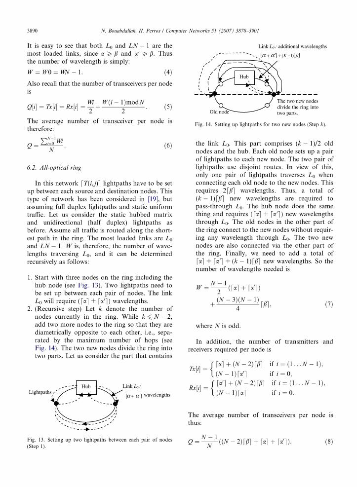
2. (Recursive step) Let k denote the number ofnodes currently in the ring. While k 6 N � 2,add two more nodes to the ring so that they arediametrically opposite to each other, i.e., sepa-rated by the maximum number of hops (seeFig. 14). The two new nodes divide the ring intotwo parts. Let us consider the part that contains
LightpathsHub Link L0 :
']αα + wavelengths[
Fig. 13. Setting up two lightpaths between each pair of nodes(Step 1).
the link L0. This part comprises (k � 1)/2 oldnodes and the hub. Each old node sets up a pairof lightpaths to each new node. The two pair oflightpaths use disjoint routes. In view of this,only one pair of lightpaths traverses L0 whenconnecting each old node to the new nodes. Thisrequires 2dbe wavelengths. Thus, a total of(k � 1)dbe new wavelengths are required topass-through L0. The hub node does the samething and requires (dae + da 0e) new wavelengthsthrough L0. The old nodes in the other part ofthe ring connect to the new nodes without requir-ing any wavelength through L0. The two newnodes are also connected via the other part ofthe ring. Finally, we need to add a total ofdae + da 0e + (k � 1)dbe new wavelengths. So thenumber of wavelengths needed is
W ¼ N � 1
2ðdae þ da0eÞ
þ ðN � 3ÞðN � 1Þ4
dbe; ð7Þ
where N is odd.
In addition, the number of transmitters andreceivers required per node is
Tx½i� ¼dae þ ðN � 2Þdbe if i ¼ ð1 . . . N � 1Þ;ðN � 1Þda0e if i ¼ 0;
�
Rx½i� ¼da0e þ ðN � 2Þdbe if i ¼ ð1 . . . N � 1Þ;ðN � 1Þdae if i ¼ 0:
�
The average number of transceivers per node isthus:
Q ¼ N � 1
NððN � 2Þdbe þ dae þ da0eÞ: ð8Þ
N. Bouabdallah, H. Perros / Computer Networks 51 (2007) 3878–3901 3891
6.3. The DBORN optical ring
As stated earlier, an intermediate node i
(i = 2, . . . ,N � 1) can use the traversing lightpathsto inject its local traffic intended to the hub node.If sufficient capacity exists, the ring node i trafficwould be carried by the spare capacity of the pass-through lightpaths. Otherwise, node i has to createnew lightpaths to handle the entire amount of itslocal traffic destined to the hub node. Here, we sup-pose that the traffic injected by the different ringnodes is perfectly multiplexed in the upstreamwavelengths.
Two algorithms can be used to realize the assign-ment of the network resources. The first minimizesthe number of wavelengths, whereas the secondminimizes the number of required transmitters ateach ring node.
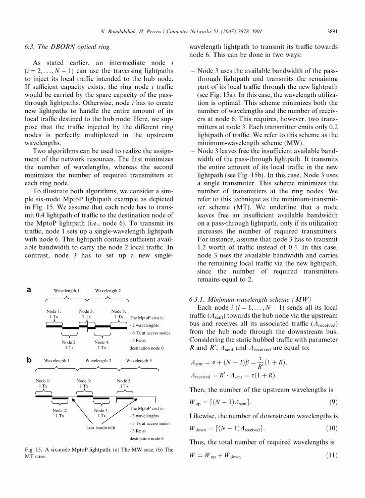
To illustrate both algorithms, we consider a sim-ple six-node MptoP lightpath example as depictedin Fig. 15. We assume that each node has to trans-mit 0.4 lightpath of traffic to the destination node ofthe MptoP lightpath (i.e., node 6). To transmit itstraffic, node 1 sets up a single-wavelength lightpathwith node 6. This lightpath contains sufficient avail-able bandwidth to carry the node 2 local traffic. Incontrast, node 3 has to set up a new single-
Wavelength 1 Wavelength 2 Wavelength 3
Node 1: 1 Tx
Node 3: 1 Tx
Node 5: 1 Tx
Node 2: 1 Tx
Node 4: 1 Tx
The MptoP cost is:
- 3 wavelenghts
- 5 Tx at access nodes
- 3 Rx at
destination node 6
Lost bandwidth
Wavelength 1 Wavelength 2
Node 1: 1 Tx
Node 3: 2 Tx
Node 5: 1 Tx
Node 2: 1 Tx
Node 4: 1 Tx
The MptoP cost is:
- 2 wavelenghts
- 6 Tx at access nodes
- 2 Rx at
destination node 6
a
b
Fig. 15. A six-node MptoP lightpath: (a) The MW case. (b) TheMT case.
wavelength lightpath to transmit its traffic towardsnode 6. This can be done in two ways:
– Node 3 uses the available bandwidth of the pass-through lightpath and transmits the remainingpart of its local traffic through the new lightpath(see Fig. 15a). In this case, the wavelength utiliza-tion is optimal. This scheme minimizes both thenumber of wavelengths and the number of receiv-ers at node 6. This requires, however, two trans-mitters at node 3. Each transmitter emits only 0.2lightpath of traffic. We refer to this scheme as theminimum-wavelength scheme (MW).
– Node 3 leaves free the insufficient available band-width of the pass-through lightpath. It transmitsthe entire amount of its local traffic in the newlightpath (see Fig. 15b). In this case, Node 3 usesa single transmitter. This scheme minimizes thenumber of transmitters at the ring nodes. Werefer to this technique as the minimum-transmit-ter scheme (MT). We underline that a nodeleaves free an insufficient available bandwidthon a pass-through lightpath, only if its utilizationincreases the number of required transmitters.For instance, assume that node 3 has to transmit1.2 worth of traffic instead of 0.4. In this case,node 3 uses the available bandwidth and carriesthe remaining local traffic via the new lightpath,since the number of required transmittersremains equal to 2.
6.3.1. Minimum-wavelength scheme (MW)
Each node i (i = 1, . . . ,N � 1) sends all its localtraffic (Ksent) towards the hub node via the upstreambus and receives all its associated traffic (Kreceived)from the hub node through the downstream bus.Considering the static hubbed traffic with parameterR and R 0, Ksent and Kreceived are equal to:
Ksent ¼ aþ ðN � 2Þb ¼ sR0ð1þ RÞ;
Kreceived ¼ R0 � Ksent ¼ sð1þ RÞ:
Then, the number of the upstream wavelengths is
W up ¼ dðN � 1ÞKsente: ð9Þ
Likewise, the number of downstream wavelengths is
W down ¼ dðN � 1ÞKreceivede: ð10Þ
Thus, the total number of required wavelengths is
W ¼ W up þ W down: ð11Þ
Both nodes share a common band of 3 wavelengths
3892 N. Bouabdallah, H. Perros / Computer Networks 51 (2007) 3878–3901
Let us consider ring node i (i = 1. . .N � 1). Node i
has to transmit Ksent lightpaths of traffic to thehub node. The available bandwidth seen by node i
on the traversing lightpaths coming from upstreamnodes (i.e., nodes 1, . . . , i � 1) is
BwðiÞ ¼ dði� 1ÞKsente � ði� 1ÞKsent:
The required number of transmitters at node i isthen:
Tx½i� ¼ dKsent � BwðiÞe þ dBwðiÞe:It can be demonstrated that the total number oftransmitters at all ring nodes (excluding the hubnode) is provided by the expression:
XN�1
i¼1
Tx½i� ¼ N � 2þ W up �XN�2
i¼1
1jdiKsente � iKsent ¼ 0:
The number of required transmitters at the hubnode is
Tx½0� ¼ W down:
Hence, the average number of transmitters per nodeis
Tx ¼ 1
N
XN�1
i¼0
Tx½i� ¼ 1
þ W � 2�PN�2
i¼1 1jdiKsente � iKsent ¼ 0
N:
ð12Þ
Similarly, we obtain the average number of receiversper node
Rx ¼ 1
N
XN�1
i¼0
RxðiÞ ¼ 1
þ W � 2�PN�2
i¼1 1jdiKreceivede � iKreceived ¼ 0
N:
ð13Þ
The average number of transceivers per node isthus:
Q ¼ Txþ Rx2
: ð14Þ
Wavelength 1 Wavelength 8
Node 1: 2 Tx
Node 3: 2 Tx
Node 5: 2 Tx
Node 2: 2 Tx
Node 4: 2 Tx
Lost bandwidth
Fig. 16. A six-node MptoP lightpath: the MT case.
6.3.2. Minimum-transmitter scheme (MT)
This scheme minimizes the number of requiredtransmitters at ring nodes. It is easy to see that eachnode i (i = 1, . . . ,N � 1) requires dKsente transmit-ters. As stated before, node i uses the availablebandwidth of a pass-through lightpath, as long asthe resulting number of required transmitters
remains equal to dKsente. In view of this, the numberof upstream wavelengths can be calculated as below.
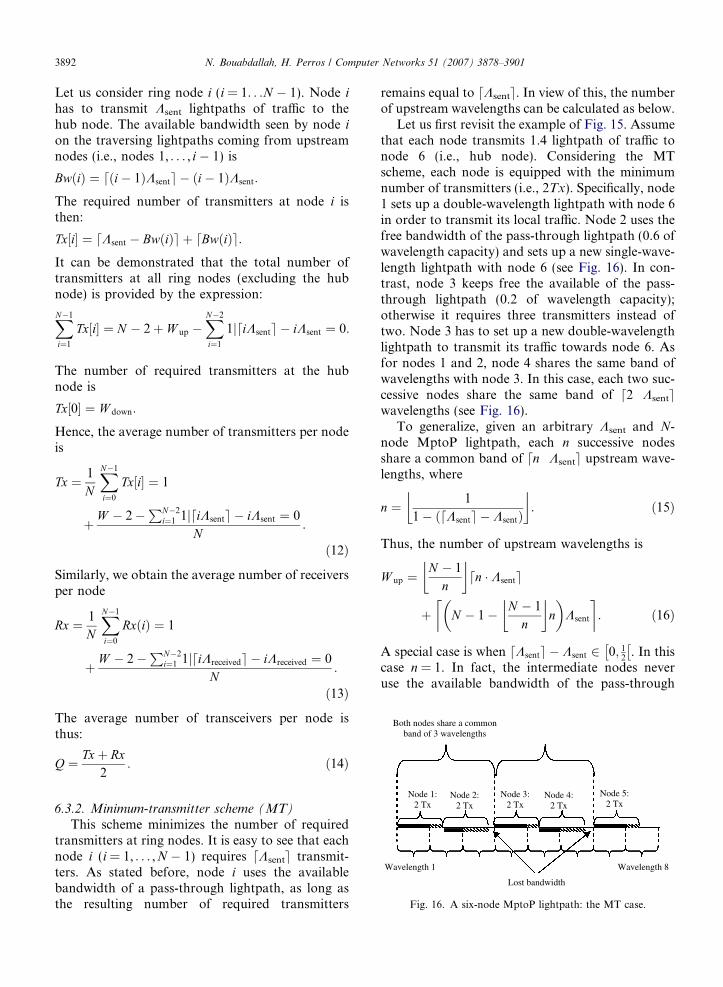
Let us first revisit the example of Fig. 15. Assumethat each node transmits 1.4 lightpath of traffic tonode 6 (i.e., hub node). Considering the MTscheme, each node is equipped with the minimumnumber of transmitters (i.e., 2Tx). Specifically, node1 sets up a double-wavelength lightpath with node 6in order to transmit its local traffic. Node 2 uses thefree bandwidth of the pass-through lightpath (0.6 ofwavelength capacity) and sets up a new single-wave-length lightpath with node 6 (see Fig. 16). In con-trast, node 3 keeps free the available of the pass-through lightpath (0.2 of wavelength capacity);otherwise it requires three transmitters instead oftwo. Node 3 has to set up a new double-wavelengthlightpath to transmit its traffic towards node 6. Asfor nodes 1 and 2, node 4 shares the same band ofwavelengths with node 3. In this case, each two suc-cessive nodes share the same band of d2 Æ Ksentewavelengths (see Fig. 16).
To generalize, given an arbitrary Ksent and N-node MptoP lightpath, each n successive nodesshare a common band of dn Æ Ksente upstream wave-lengths, where
n ¼ 1
1� ðdKsente � KsentÞ
� �: ð15Þ
Thus, the number of upstream wavelengths is
W up ¼N � 1
n
� �dn � Ksente
þ N � 1� N � 1
n
� �n
Ksent
� �: ð16Þ
A special case is when dKsente � Ksent 2 0; 12
� �. In this
case n = 1. In fact, the intermediate nodes neveruse the available bandwidth of the pass-through
N. Bouabdallah, H. Perros / Computer Networks 51 (2007) 3878–3901 3893
lightpaths. The number of upstream wavelengths istherefore:
W up ¼ ðN � 1ÞdKsente:
Likewise, we derive the number of downstreamwavelengths:
W down ¼N � 1
n0
� �dn0 � Kreceivede
þ N � 1� N � 1
n0
� �n
Kreceived
� �; ð17Þ
where
n0 ¼ 1
1� dKreceivede � Kreceivedð Þ
� �:
Thus, the total number of required wavelengths is
W ¼ W up þ W down: ð18Þ
Recall that the number of transmitters and receiversrequired per node is
Tx½i� ¼dKsente if i ¼ ð1 . . . N � 1Þ;W down if i ¼ 0;
�
Rx½i� ¼dKreceivede if i ¼ ð1 . . . N � 1Þ:W up; if i ¼ 0:
�
The average number of transceivers per node istherefore:
Q ¼ ðN � 1ÞðdKsente þ dKreceivedeÞ þ W2N
: ð19Þ
6.4. The MptoP all-optical ring
In this network, each node i(i = 0, . . . ,N � 1)has to set up two lightpaths with the farthestnodes of the ring (i.e., nodes iþ N�1
2
� �mod N and
i� N�12
� �mod NÞ. To reach the remaining ring
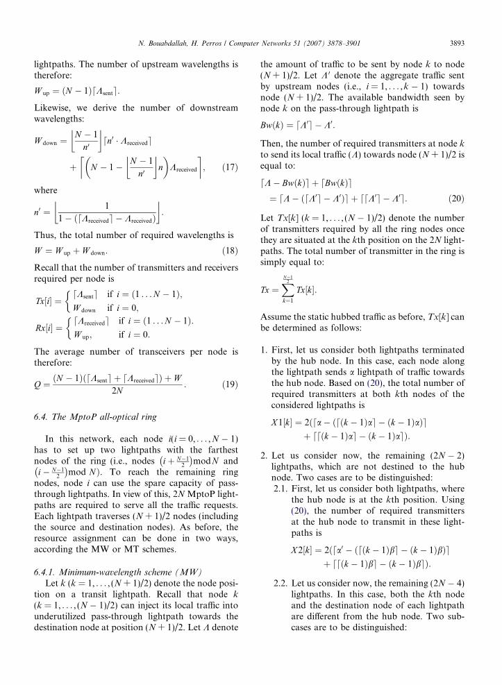
nodes, node i can use the spare capacity of pass-through lightpaths. In view of this, 2N MptoP light-paths are required to serve all the traffic requests.Each lightpath traverses (N + 1)/2 nodes (includingthe source and destination nodes). As before, theresource assignment can be done in two ways,according the MW or MT schemes.
6.4.1. Minimum-wavelength scheme (MW)
Let k (k = 1, . . . , (N + 1)/2) denote the node posi-tion on a transit lightpath. Recall that node k
(k = 1, . . . , (N � 1)/2) can inject its local traffic intounderutilized pass-through lightpath towards thedestination node at position (N + 1)/2. Let K denote
the amount of traffic to be sent by node k to node(N + 1)/2. Let K 0 denote the aggregate traffic sentby upstream nodes (i.e., i = 1, . . . ,k � 1) towardsnode (N + 1)/2. The available bandwidth seen bynode k on the pass-through lightpath is
BwðkÞ ¼ dK0e � K0:
Then, the number of required transmitters at node k
to send its local traffic (K) towards node (N + 1)/2 isequal to:
dK� BwðkÞe þ dBwðkÞe¼ dK� ðdK0e � K0Þe þ ddK0e � K0e: ð20Þ
Let Tx[k] (k = 1, . . . , (N � 1)/2) denote the numberof transmitters required by all the ring nodes oncethey are situated at the kth position on the 2N light-paths. The total number of transmitter in the ring issimply equal to:
Tx ¼XN�1
2
k¼1
Tx½k�:
Assume the static hubbed traffic as before, Tx[k] canbe determined as follows:
1. First, let us consider both lightpaths terminatedby the hub node. In this case, each node alongthe lightpath sends a lightpath of traffic towardsthe hub node. Based on (20), the total number ofrequired transmitters at both kth nodes of theconsidered lightpaths is
X 1½k� ¼ 2ðda� ðdðk � 1Þae � ðk � 1ÞaÞeþ ddðk � 1Þae � ðk � 1ÞaeÞ:
2. Let us consider now, the remaining (2N � 2)lightpaths, which are not destined to the hubnode. Two cases are to be distinguished:2.1. First, let us consider both lightpaths, where
the hub node is at the kth position. Using(20), the number of required transmittersat the hub node to transmit in these light-paths is
X 2½k� ¼ 2ðda0 � ðdðk � 1Þbe � ðk � 1ÞbÞeþ ddðk � 1Þbe � ðk � 1ÞbeÞ:
2.2. Let us consider now, the remaining (2N � 4)lightpaths. In this case, both the kth nodeand the destination node of each lightpathare different from the hub node. Two sub-cases are to be distinguished:
3894 N. Bouabdallah, H. Perros / Computer Networks 51 (2007) 3878–3901
2.2.1. The hub node is one of the upstreamnodes traversed by the lightpath beforepassing-through node k. That is, thehub node has the position i on the light-path where i = 1. . .k � 1. This is the caseof 2(k � 1) lightpaths. Using (20), thetotal number of required transmitters atall the nodes situated at the kth positionto transmit in the considered lightpaths is
X 3½k� ¼ 2ðk�1Þ db�ðdðk�2Þbþa0eð�ððk�2Þbþa0ÞÞeþddðk�2Þbþa0e�ððk�2Þbþa0ÞeÞ:
2.2.2. In this case, all the nodes at the ith posi-tion (i = 1. . .k) of a lightpath are differ-ent from the hub node. This is the caseof the remaining 2(N � 1 � k) lightpaths.Based on (20), the total number ofrequired transmitters at all the nodes sit-uated at the kth position to transmit inthe considered lightpaths is
X 4½k�¼2ðN�1�kÞ db�ðdðk�1Þbeð�ðk�1ÞbÞeþddðk�1Þbe�ðk�1ÞbeÞ:
Ring node 1
Hub node (# 0)
Ring node N-1 Link L0
Ring node
(N-1)/2
Ring node
(N+3)/2
Ring node
(N+1)/2
Fig. 17. MptoP WDM ring: lightpaths passing through link L0.
Finally the total number of transmitters neededin the ring is
Tx ¼XN�1
2
k¼1
X 1½k� þ X 2½k� þ X 3½k� þ X 4½k�: ð21Þ
With regard to the reception part, each nodei(i = 0, . . . ,N � 1) receives two MptoP lightpathscarrying the aggregate traffic coming from both halfof the ring as shown in Fig. 4. Each half has(N � 1)/2 ring nodes. The number of receivers atnode i is simply:
Rx½i� ¼dN�3
2bþ a0e þ dN�1
2be if i ¼ ð1 . . . N � 1Þ;
2dN�12
ae if i ¼ 0:
(
Hence, the total number of required receivers in thering is
Rx ¼XN�1
i¼0
Rx½i�: ð22Þ
The average number of transceivers per node istherefore:
Q ¼ Txþ Rx2N
: ð23Þ
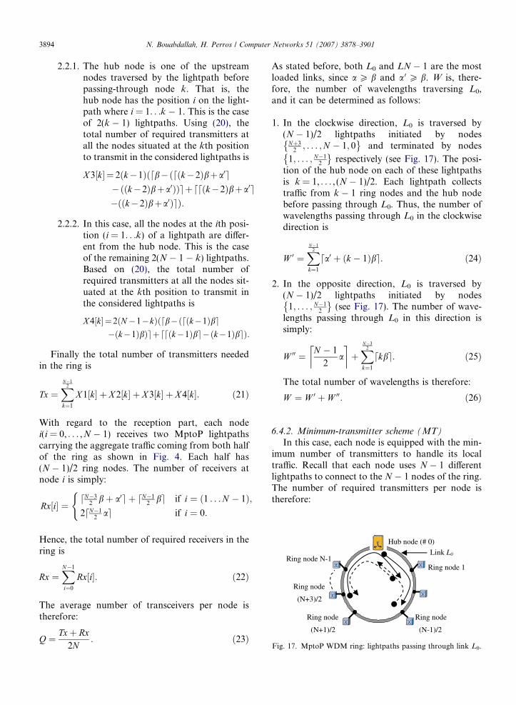
As stated before, both L0 and LN � 1 are the mostloaded links, since a P b and a 0 P b. W is, there-fore, the number of wavelengths traversing L0,and it can be determined as follows:
1. In the clockwise direction, L0 is traversed by(N � 1)/2 lightpaths initiated by nodes
Nþ32; . . . ;N � 1; 0
� and terminated by nodes
1; . . . ; N�12
� respectively (see Fig. 17). The posi-
tion of the hub node on each of these lightpathsis k = 1, . . . , (N � 1)/2. Each lightpath collectstraffic from k � 1 ring nodes and the hub nodebefore passing through L0. Thus, the number ofwavelengths passing through L0 in the clockwisedirection is
W 0 ¼XN�1
2
k¼1
da0 þ ðk � 1Þbe: ð24Þ
2. In the opposite direction, L0 is traversed by(N � 1)/2 lightpaths initiated by nodes
1; . . . ; N�12
� (see Fig. 17). The number of wave-
lengths passing through L0 in this direction issimply:
W 00 ¼ N � 1
2a
� �þXN�3
2
k¼1
dkbe: ð25Þ
The total number of wavelengths is therefore:
W ¼ W 0 þ W 00: ð26Þ
6.4.2. Minimum-transmitter scheme (MT)
In this case, each node is equipped with the min-imum number of transmitters to handle its localtraffic. Recall that each node uses N � 1 differentlightpaths to connect to the N � 1 nodes of the ring.The number of required transmitters per node istherefore:
N. Bouabdallah, H. Perros / Computer Networks 51 (2007) 3878–3901 3895
Tx½i� ¼dae þ ðN � 2Þdbe if i ¼ ð1 . . . N � 1Þ;ðN � 1Þda0e if i ¼ 0:
�
Hence, the total number of required transmitters inthe ring is
Tx ¼XN�1
i¼0
Tx½i�: ð27Þ
With regard to the reception part, each nodei(i = 1, . . . ,N � 1) (excluding the hub) receives twoMptoP lightpaths carrying the aggregate trafficcoming from both half of the ring as shown inFig. 4. Each half has (N � 1)/2 ring nodes. Thenumber of required receivers at node i can be deter-minated as follows:
1. First, let us consider the half that does not con-tain the hub node. In this case, each node alongthe MptoP lightpath sends b worth of traffic tonode i. According to the MT scheme (16), eachn successive nodes share a common band of dnbewavelengths, where:
n ¼ 1
1� ðdbe � bÞ
� �:
Hence, the number of required receivers at node i
to terminate the wavelengths coming from thishalf of the ring is
Rx1 ¼ N � 1
2n
� �dnbe
þ N � 1
2� N � 1
2n
� �n
b
� �: ð28Þ
2. Let us consider now, the half that contains thehub node. In this case, the number of receiversat node i depends on its relative position withrespect to the hub node. To simplify the analysis,we suppose that the hub node always creates itsown da 0e-wavelength lightpath to connect tonode i. That is, the MptoP lightpath travelingto node i is shared by the remaining (N � 3)/2ring nodes. Note that this approximation willincrease the real number of required receivers atnode i at most by a factor one. The number ofrequired receivers at node i to terminate thewavelengths coming from this half of the ring istherefore:
Rx2 ¼ da0e þ N � 3
2n
� �dnbe
þ N � 3
2� N � 3
2n
� �n
b
� �; ð29Þ
where n ¼ 11�ðdbe�bÞ
j k.
Thus, the number of required receivers at eachnode i(i = 1, . . . ,N � 1) is
Rx½i� ¼ Rx1þ Rx2: ð30Þ
Likewise, the hub node receives two MptoP light-paths coming from both parts of the ring. EachMptoP lightpath is shared by (N � 1)/2 ring nodes.Each node along the lightpath transmits a worth oftraffic towards the hub node. Thus, the number ofrequired receivers at the hub node is
Rx½0� ¼ 2N �1
2n
� �dnaeþ N �1
2� N �1
2n
� �n
a
� � ;
ð31Þ
with
n ¼ 1
1� ðdae � aÞ
� �:
Hence, the total number of required receivers in thering is
Rx ¼XN�1
i¼0
Rx½i�: ð32Þ
The average number of transceivers per node istherefore:
Q ¼ Txþ Rx2N
: ð33Þ
As before, W is the number of wavelengths travers-ing L0, and it can be determined as follows:
1. In the clockwise direction, L0 is traversedby (N � 1)/2 lightpaths initiated by nodes
Nþ32; . . . ;N � 1; 0
� and terminated by nodes
1; . . . ; N�12
� respectively (see Fig. 17). The posi-
tion of the hub node on each of these lightpathsis k = 1, . . . , (N � 1)/2. Let lightpath k refer toeach of these lightpaths according the hub nodeposition. Lightpath k collects traffic from k � 1ring nodes and the hub node before passingthrough L0. To simplify the analysis, we supposethat the hub node sets up its own da 0e-wavelength
3896 N. Bouabdallah, H. Perros / Computer Networks 51 (2007) 3878–3901
lightpath to connect directly to each ring node.Thus, the number of wavelengths passingthrough L0 and required by lightpath k is
W 0½k� ¼ da0e þ k � 1
n
� �dnbe
þ k � 1� k � 1
n
� �n
b
� �;
with
n ¼ 1
1� ðdbe � bÞ
� �:
The total number of required wavelengths in theclockwise direction through L0 is therefore:
W 0 ¼XN�1
2
k¼1
W 0½k�: ð34Þ
2. In the opposite direction, L0 is traversed by(N � 1)/2 lightpaths initiated by nodes
1; . . . ; N�12
� (see Fig. 17). The position of the
hub node on each of these lightpaths isk = 2, . . . , (N + 1)/2. Let lightpath k refer to eachof these lightpaths according the hub node posi-tion. Lightpath k collects traffic from k � 1 ringnodes before passing through L0. As before, thenumber of wavelengths passing through L0 andrequired by lightpath k is simply:
W 00½k� ¼
k�1n
� �dnbe þ k � 1� k�1
n
� �n
� �b
� �;
if k ¼ 2; . . . ; N�12
N�12n0
� �dn0ae þ N�1
2� N�1
2n0
� �n0
� �a
� �;
if k ¼ Nþ12;
8>>><>>>:
with
n ¼ 1
1� ðdbe � bÞ
� �and n0 ¼ 1
1� ðdae � aÞ
� �:
0 2 4 6 8 10 12 14 16 18 200
5
10
15
20
25
30
The entire amount of local traffic handled by each ring node
Ave
rage
num
ber
of tr
ansc
eive
rs p
er n
ode
(Q)
OpaqueAll-opticalDBORN-MTMptoP-MT
OpaqueAll-opticalDBORN-MTMptoP-MT
0 2 4 6 8 100
5
10
15
20
25
30
35
The entire amount of local traffic
Ave
rage
num
ber
of tr
ansc
eive
rs p
er n
ode
(Q)
Fig. 18. The transceiver requirement per node in the WDM ring netwo(b) case R 0 = 2 and (c) case R 0 = 4.
The total number of wavelengths passingthrough L0 in this direction is therefore:
W 00 ¼XNþ1
2
k¼2
W 00½k�: ð35Þ
The total number of wavelengths is therefore:
W ¼ W 0 þ W 00: ð36Þ
7. Cost comparison
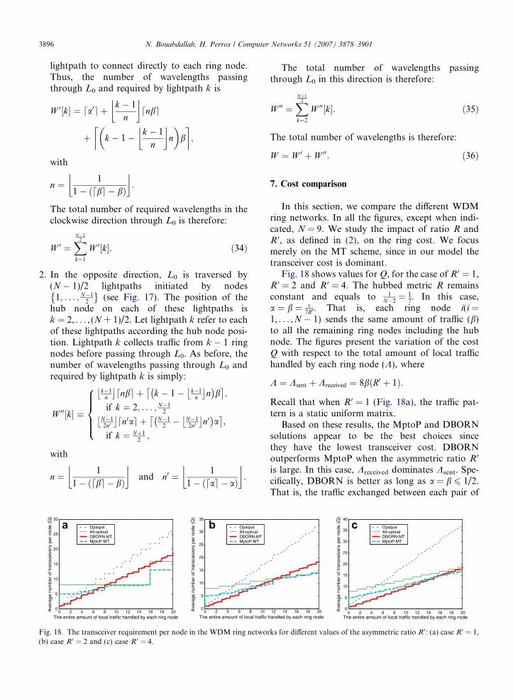
In this section, we compare the different WDMring networks. In all the figures, except when indi-cated, N = 9. We study the impact of ratio R andR 0, as defined in (2), on the ring cost. We focusmerely on the MT scheme, since in our model thetransceiver cost is dominant.
Fig. 18 shows values for Q, for the case of R 0 = 1,R 0 = 2 and R 0 = 4. The hubbed metric R remainsconstant and equals to 1
N�2¼ 1
7. In this case,
a ¼ b ¼ s7R0. That is, each ring node i(i =
1, . . . ,N � 1) sends the same amount of traffic (b)to all the remaining ring nodes including the hubnode. The figures present the variation of the costQ with respect to the total amount of local traffichandled by each ring node (K), where
K ¼ Ksent þ Kreceived ¼ 8bðR0 þ 1Þ:
Recall that when R 0 = 1 (Fig. 18a), the traffic pat-tern is a static uniform matrix.
Based on these results, the MptoP and DBORNsolutions appear to be the best choices sincethey have the lowest transceiver cost. DBORNoutperforms MptoP when the asymmetric ratio R 0
is large. In this case, Kreceived dominates Ksent. Spe-cifically, DBORN is better as long as a = b 6 1/2.That is, the traffic exchanged between each pair of
OpaqueAll-opticalDBORN-MTMptoP-MT
12 14 16 18 20handled by each ring node
0 2 4 6 8 10 12 14 16 18 200
5
10
15
20
25
30
35
40
The entire amount of local traffic handled by each ring node
Ave
rage
num
ber
of tr
ansc
eive
rs p
er n
ode
(Q)
rks for different values of the asymmetric ratio R 0: (a) case R 0 = 1,
N. Bouabdallah, H. Perros / Computer Networks 51 (2007) 3878–3901 3897
nodes is relatively small. For instance, this isachieved as long as K 6 8 when R 0 = 1. Recall thata DBORN node transmits all its traffic (Ksent = 8b)towards the hub node, thus using a single lightpath.Instead, a MptoP ring node has to set up N � 1lightpaths in order to transmit its local traffic tothe remaining nodes of the ring. In view of this,the traffic grooming in DBORN nodes is higherthan in the MptoP nodes. To achieve this, theDBORN hub node has to deal with all the trafficin the ring, thus requiring a maximum transceivercost. In this regard, the cost gain achieved byDBORN at the ring nodes level is lost at the hubnode when b becomes relatively large.
The all-optical ring is also a reasonable choiceonly if the traffic between each pair of nodes is highenough to fill in the entire lightpaths capacity. Opa-que rings typically have the highest transceiver costsince the nodes do not have optical pass-through.
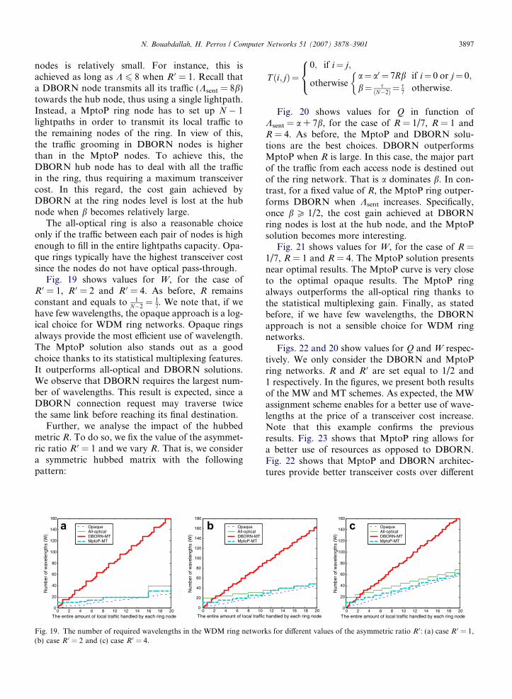
Fig. 19 shows values for W, for the case ofR 0 = 1, R 0 = 2 and R 0 = 4. As before, R remainsconstant and equals to 1
N�2¼ 1
7. We note that, if we
have few wavelengths, the opaque approach is a log-ical choice for WDM ring networks. Opaque ringsalways provide the most efficient use of wavelength.The MptoP solution also stands out as a goodchoice thanks to its statistical multiplexing features.It outperforms all-optical and DBORN solutions.We observe that DBORN requires the largest num-ber of wavelengths. This result is expected, since aDBORN connection request may traverse twicethe same link before reaching its final destination.
Further, we analyse the impact of the hubbedmetric R. To do so, we fix the value of the asymmet-ric ratio R 0 = 1 and we vary R. That is, we considera symmetric hubbed matrix with the followingpattern:
OpaqueAll-opticalDBORN-MTMptoP-MT
OpaqueAll-opticalDBORN-MTMptoP-MT
0 2 4 6 8 10 12 14 16 18 200
20
40
60
80
100
120
140
160
The entire amount of local traffic handled by each ring node
Num
ber
of w
avel
engt
hs (
W)
0 2 4 6 8 100
20
40
60
80
100
120
140
160
180
The entire amount of local traffic
Num
ber
of w
avel
engt
hs (
W)
Fig. 19. The number of required wavelengths in the WDM ring networ(b) case R 0 = 2 and (c) case R 0 = 4.
T ði;jÞ¼0; if i¼ j;
otherwisea¼ a0 ¼ 7Rb if i¼ 0 or j¼ 0;
b¼ sðN�2Þ ¼ s
7otherwise:
�8<:
Fig. 20 shows values for Q in function ofKsent = a + 7b, for the case of R = 1/7, R = 1 andR = 4. As before, the MptoP and DBORN solu-tions are the best choices. DBORN outperformsMptoP when R is large. In this case, the major partof the traffic from each access node is destined outof the ring network. That is a dominates b. In con-trast, for a fixed value of R, the MptoP ring outper-forms DBORN when Ksent increases. Specifically,once b P 1/2, the cost gain achieved at DBORNring nodes is lost at the hub node, and the MptoPsolution becomes more interesting.
Fig. 21 shows values for W, for the case of R =1/7, R = 1 and R = 4. The MptoP solution presentsnear optimal results. The MptoP curve is very closeto the optimal opaque results. The MptoP ringalways outperforms the all-optical ring thanks tothe statistical multiplexing gain. Finally, as statedbefore, if we have few wavelengths, the DBORNapproach is not a sensible choice for WDM ringnetworks.
Figs. 22 and 20 show values for Q and W respec-tively. We only consider the DBORN and MptoPring networks. R and R 0 are set equal to 1/2 and1 respectively. In the figures, we present both resultsof the MW and MT schemes. As expected, the MWassignment scheme enables for a better use of wave-lengths at the price of a transceiver cost increase.Note that this example confirms the previousresults. Fig. 23 shows that MptoP ring allows fora better use of resources as opposed to DBORN.Fig. 22 shows that MptoP and DBORN architec-tures provide better transceiver costs over different
OpaqueAll-opticalDBORN-MTMptoP-MT
12 14 16 18 20 handled by each ring node
0 2 4 6 8 10 12 14 16 18 200
20
40
60
80
100
120
140
160
The entire amount of local traffic handled by each ring node
Num
ber
of w
avel
engt
hs (
W)
ks for different values of the asymmetric ratio R 0: (a) case R 0 = 1,
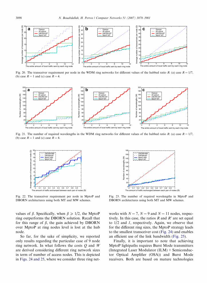
0 2 4 6 8 10 120
5
10
15
20
25
30
The entire amount of local traffic sent by each ring node
Ave
rage
num
ber
of tr
ansc
eive
rs p
er n
ode
(Q)
OpaqueAll-opticalDBORN-MTMptoP-MT
OpaqueAll-opticalDBORN-MTMptoP-MT
OpaqueAll-opticalDBORN-MTMptoP-MT
0 2 4 6 8 10 120
5
10
15
20
25
30
35
40
45
The entire amount of local traffic sent by each ring node
Ave
rage
num
ber
of tr
ansc
eive
rs p
er n
ode
(Q)
0 2 4 6 8 10 120
5
10
15
20
25
30
35
40
45
50
The entire amount of local traffic sent by each ring node
Ave
rage
num
ber
of tr
ansc
eive
rs p
er n
ode
(Q)
Fig. 20. The transceiver requirement per node in the WDM ring networks for different values of the hubbed ratio R: (a) case R = 1/7,(b) case R = 1 and (c) case R = 4.
0 2 4 6 8 10 120
20
40
60
80
100
120
140
160
180
200
The entire amount of local traffic sent by each ring node
Num
ber
of w
avel
engt
hs (
W)
0 2 4 6 8 10 12
The entire amount of local traffic sent by each ring node
Num
ber
of w
avel
engt
hs (
W)
0 2 4 6 8 10 120
20
40
60
80
100
120
140
160
180
200
0
20
40
60
80
100
120
140
160
180
200
The entire amount of local traffic sent by each ring node
Num
ber
of w
avel
engt
hs (
W)Opaque
All-opticalDBORN-MTMptoP-MT
OpaqueAll-opticalDBORN-MTMptoP-MT
OpaqueAll-opticalDBORN-MTMptoP-MT
Fig. 21. The number of required wavelengths in the WDM ring networks for different values of the hubbed ratio R: (a) case R = 1/7,(b) case R = 1 and (c) case R = 4.
0 0.1 0.2 0.3 0.4 0.5 0.6 0.7 0.8 0.9 10
2
4
6
8
10
12
14
16
18
20
The amount of traffic exchanged between each pair of nodes (B)
Ave
rage
num
ber
of tr
ansc
eive
rs p
er n
ode
(Q)
DBORN-MWDBORN-MTMptoP-MWMptoP-MT
Fig. 22. The transceiver requirement per node in MptoP andDBORN architectures using both MT and MW schemes.
0 0.1 0.2 0.3 0.4 0.5 0.6 0.7 0.8 0.9 10
20
40
60
80
100
120
140
160
180
The amount of traffic exchanged between each pair of nodes (B)
Num
ber
of w
avel
engt
hs (
W)
DBORN-MWDBORN-MTMptoP-MWMptoP-MT
Fig. 23. The number of required wavelengths in MptoP andDBORN architectures using both MT and MW schemes.
3898 N. Bouabdallah, H. Perros / Computer Networks 51 (2007) 3878–3901
values of b. Specifically, when b P 1/2, the MptoPring outperforms the DBORN solution. Recall thatfor this range of b, the gain achieved by DBORNover MptoP at ring nodes level is lost at the hubnode.
So far, for the sake of simplicity, we reportedonly results regarding the particular case of 9 nodering network. In what follows the costs Q and W
are derived considering different ring network sizesin term of number of access nodes. This is depictedin Figs. 24 and 25, where we consider three ring net-
works with N = 7, N = 9 and N = 11 nodes, respec-tively. In this case, the ratios R and R 0 are set equalto 1/2 and 1, respectively. Again, we observe thatfor the different ring sizes, the MptoP strategy leadsto the smallest transceiver cost (Fig. 24) and enablesan efficient use of the link bandwidth (Fig. 25).
Finally, it is important to note that achievingMptoP lightpaths requires Burst Mode transmitters(Integrated Laser Modulator (ILM) + Semiconduc-tor Optical Amplifier (OSA)) and Burst Modereceivers. Both are based on mature technologies
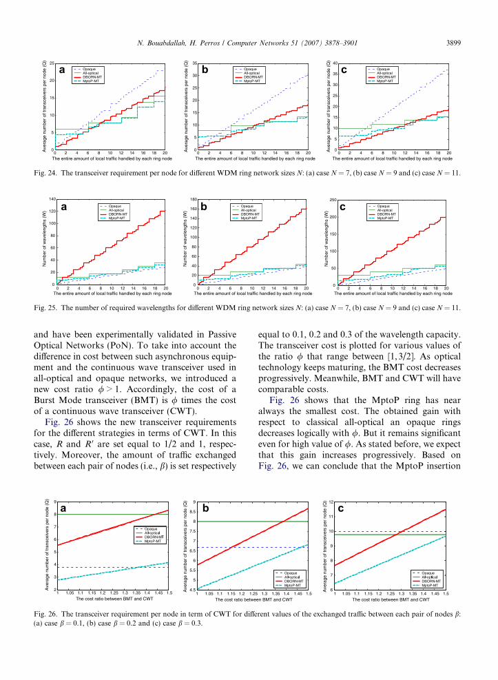
0 2 4 6 8 10 12 14 16 18 200
5
10
15
20
25
The entire amount of local traffic handled by each ring node0 2 4 6 8 10 12 14 16 18 20
The entire amount of local traffic handled by each ring node The entire amount of local traffic handled by each ring node
Ave
rage
num
ber
of tr
ansc
eive
rs p
er n
ode
(Q)
Ave
rage
num
ber
of tr
ansc
eive
rs p
er n
ode
(Q)
Ave
rage
num
ber
of tr
ansc
eive
rs p
er n
ode
(Q)
OpaqueAll-opticalDBORN-MTMptoP-MT
OpaqueAll-opticalDBORN-MTMptoP-MT
OpaqueAll-opticalDBORN-MTMptoP-MT
0
5
10
15
20
25
30
35
0 2 4 6 8 10 12 14 16 18 200
5
10
15
20
25
30
35
40
Fig. 24. The transceiver requirement per node for different WDM ring network sizes N: (a) case N = 7, (b) case N = 9 and (c) case N = 11.
0 2 4 6 8 10 12 14 16 18 200
20
40
60
80
100
120
140
The entire amount of local traffic handled by each ring node0 2 4 6 8 10 12 14 16 18 20
The entire amount of local traffic handled by each ring node0 2 4 6 8 10 12 14 16 18 20
The entire amount of local traffic handled by each ring node
Num
ber
of w
avel
engt
hs (
W)
Num
ber
of w
avel
engt
hs (
W)
Num
ber
of w
avel
engt
hs (
W)
OpaqueAll-opticalDBORN-MTMptoP-MT
OpaqueAll-opticalDBORN-MTMptoP-MT
OpaqueAll-opticalDBORN-MTMptoP-MT
0
20
40
60
80
100
120
140
160
180
0
50
100
150
200
250
Fig. 25. The number of required wavelengths for different WDM ring network sizes N: (a) case N = 7, (b) case N = 9 and (c) case N = 11.
N. Bouabdallah, H. Perros / Computer Networks 51 (2007) 3878–3901 3899
and have been experimentally validated in PassiveOptical Networks (PoN). To take into account thedifference in cost between such asynchronous equip-ment and the continuous wave transceiver used inall-optical and opaque networks, we introduced anew cost ratio / > 1. Accordingly, the cost of aBurst Mode transceiver (BMT) is / times the costof a continuous wave transceiver (CWT).
Fig. 26 shows the new transceiver requirementsfor the different strategies in terms of CWT. In thiscase, R and R 0 are set equal to 1/2 and 1, respec-tively. Moreover, the amount of traffic exchangedbetween each pair of nodes (i.e., b) is set respectively
1 1.1 1.15 1.2 1.25 1.3 1.35 1.4 1.45 1.52
3
4
5
6
7
8
9
The cost ratio between BMT and CWT
Ave
rage
num
ber
of tr
ansc
eive
rs p
er n
ode
(Q)
Ave
rage
num
ber
of tr
ansc
eive
rs p
er n
ode
(Q)
OpaqueAll-opticalDBORN-MTMptoP-MT
4.5
5
5.5
6
6.5
7
7.5
8
8.5
9
1.05 1 1.1 1.15 1.2 1.25
The cost ratio betwe1.05
l- lT
Fig. 26. The transceiver requirement per node in term of CWT for diffe(a) case b = 0.1, (b) case b = 0.2 and (c) case b = 0.3.
equal to 0.1, 0.2 and 0.3 of the wavelength capacity.The transceiver cost is plotted for various values ofthe ratio / that range between [1, 3/2]. As opticaltechnology keeps maturing, the BMT cost decreasesprogressively. Meanwhile, BMT and CWT will havecomparable costs.
Fig. 26 shows that the MptoP ring has nearalways the smallest cost. The obtained gain withrespect to classical all-optical an opaque ringsdecreases logically with /. But it remains significanteven for high value of /. As stated before, we expectthat this gain increases progressively. Based onFig. 26, we can conclude that the MptoP insertion
Ave
rage
num
ber
of tr
ansc
eive
rs p
er n
ode
(Q)
OpaqueAll-opticalDBORN-MTMptoP-MT
6
7
8
9
10
11
12
OpaqueAll-opticalDBORN-MTMptoP-MT
1.3 1.35 1.4 1.45 1.5
en BMT and CWT 1 1.1 1.15 1.2 1.25 1.3 1.35 1.4 1.45 1.5
The cost ratio between BMT and CWT 1.05
l- l l- ti l
rent values of the exchanged traffic between each pair of nodes b:
3900 N. Bouabdallah, H. Perros / Computer Networks 51 (2007) 3878–3901
enables great cost savings despite the relatively highcost of the needed BMT.
In summary, most of the time, the MptoP ringhas the smallest transceiver cost and leads to an effi-cient use of the wavelength resources. This architec-ture combines the merits of optical pass-through,leading to great savings on the transceiver cost,and statistical multiplexing gain, which allows anefficient use of the wavelengths. The DBORN archi-tecture is also a good choice if the wavelengths areplentiful. In this case, the transceiver savings overthe MptoP solution increase with the increase of Rand R 0, and decreases with the increase of b.
8. Conclusion
In this paper, we considered single-hub WDMring networks. We proposed a new architecturefor such ring networks. This approach combinesthe merits of both the optical bypass of all-opticalwavelength routing and the multiplexing gain ofsub-wavelength routing. A cost comparison forour proposed scheme and existing solutions wasgiven. Results show that our proposal always hasthe smallest transceiver cost and provides an effi-cient use of the wavelength resources.
References
[1] Mike J. O’ Mahony et al., The application of optical packetswitching in future communication networks, IEEE Com-mun. Mag. (March) (2001) 128–135.
[2] N. Bouandallah, E. Dotaro, L. Ciavaglia, N. Le Sauze, G.Pujolle, Resolving the fairness issue in bus-based opti-cal access networks, IEEE Commun. Mag. 42 (11) (2004)2–8.
[3] E. Modiano, P.J. Lin, Traffic grooming in WDM networks,IEEE Commun. Mag. 39 (7) (2001) 124–129.
[4] O. Gerstel, R. Ramaswani, G.H. Sasaki, Cost-effective trafficgrooming in WDM rings, IEEE/ACM Transactions onNetworking 8 (5) (2000) 618–630.
[5] H. Zhang, J.P. Jue, B. Mukherjee, Capacity allocation andcontention resolution in a photonic slot routing all-opticalWDM mesh network, IEEE/OSA J. Light. Tech. 18 (12)(2000).
[6] T. Battistilli, H. Perros, An introduction to optical burstswitching, IEEE Commun. Mag. 41 (8) (2003) S10–S15.
[7] K. Zhu, B. Mukherjee, Traffic grooming in an optical WDMmesh network, IEEE J. Select. Areas Commun. 20 (January)(2002) 122–133.
[8] M. Mellia, E. Leonardi, M. Feletig, R. Gaudino, F. Neri,Exploiting OTDM technology in WDM networks, in:Proceedings of the IEEE INFOCOM’ 2002, New York,USA, June 2002, pp. 1822–1831.
[9] F. Farahmand, X. Huang, J.P. Jue, Efficient online trafficgrooming algorithms in WDM mesh networks with drop-and-continue node architecture, in: Proceedings, BroadNets2004, San Jose, CA, October 2004, pp. 180–189.
[10] I. Widjaja, I. Saniee, R. Giles, D. Mitra, Light core andintelligent edge for a flexible, thin-layered, and cost-effectiveoptical transport network, IEEE Opt. Commun. (May)(2003) S30–S36.
[11] A. Gumaste, I. Chlamtac, Light-trails: a novel conceptualframework for conducting optical communications, Wksp.High Perf. Switch. Rout. (June) (2003) 251–256.
[12] A. Gumaste, Light-Trails and Light-Frame Architectures forOptical Networks, Ph.D. Thesis, Fall 2003, UT-Dallas.<www.cotrion.com/light-trails>.
[13] B. Mukherjee, Optical Communication Networks, Mc-Graw-Hill, New York, 1997.
[14] S. Balasubramanian, A. Kamal, A.K. Somani, Mediumaccess control protocols for light-trail and light-bus net-works, in: Proceedings of the 8th IFIP Working Conferenceon Optical Networking Design and Modeling (February),2004.
[15] N.A. VanderHorn, M. Mina, A.K. Somani, Light-trails: apassive optical networking solution for wavelength sharingin the metro, Wksp. High Capacity Opt. Net. and EnablingTechnologies (December) (2004).
[16] N. Bouandallah, A.L. Beylot, E. Dotaro, G. Pujolle,Resolving the fairness issues in bus-based optical accessnetworks, IEEE J. Select. Areas Commun. 23 (8) (2005)1444–1457.
[17] R. Gaudino, et al., RINGO: a WDM ring optical packetnetwork demonstrator, in: Proceedings of ECOC ’01, vol. 4,Amsterdam, Netherlands, September 2001, pp. 620–621.
[18] G. Kramer, G. Pesavento, Ethernet passive optical network(EPON): building a next-generation optical access network,IEEE Commun. Mag. (February) (2002) 66–73.
[19] O. Gerstel, R. Ramaswami, Cost effective traffic grooming inWDM rings, Proceedings of IEEE Infocom 1998 1 (1998)69–77.
Nizar Bouabdallah received the B.S.degree in Telecommunications Engi-neering from Ecole Superieur des Com-munications (Sup’Com), Tunis, Tunisia,in 2001, and the M.S. and Ph.D. degreesin network and computer science fromthe University of Paris VI, Paris, France,in 2002 and 2004, respectively. He joinedAlcatel Research Laboratories, Mar-coussis, France, in 2002, while workingon his Ph.D. degree. In 2005, he was with
the North Carolina State University, Raleigh, NC, USA, as aPostdoctoral Fellow.
He is currently a researcher at INRIA (Institut National deRecherche en Informatique et en Automatique). Since February2007, he is a Visitor Researcher at the School of Computer Sci-ence, University of Waterloo, Waterloo, ON, Canada. Hisresearch interests include optical networking, wireless and sensornetworks, performance evaluation, network planning and model-ing, as well as control and management architectures.
N. Bouabdallah, H. Perros / Computer Networks 51 (2007) 3878–3901 3901
Harry G. Perros is a Professor of Com-puter Science, an Alumni DistinguishedGraduate Professor, and the ProgramCoordinator of the Master of Sciencedegree in Computer Networks at NCState University.
He received the B.Sc. degree inMathematics in 1970 from Athens Uni-versity, Greece, the M.Sc. degree inOperational Research with Computingfrom Leeds University, England, in 1971,
and the Ph.D. degree in Operations Research from Trinity Col-lege Dublin, Ireland, in 1975. He has held visiting faculty posi-
tions at INRIA, Rocquencourt, France (1979), NORTEL,Research Triangle Park, North Carolina (1988–1989 and 1995–1996), University of Paris 6, France (1995–1996, 2000, and 2002),University of Paris 13, France (2005–2006), and Victoria Uni-versity, Wellington, New Zealand (2006).He has published extensively in the area of performancemodelling of computer and communication systems, and he has
organized several national and international conferences. He hasalso published three print books: Queueing Networks with
Blocking: Exact and Approximate Solutions, Oxford UniversityPress 1994, An Introduction to ATM Networks, Wiley 2001,Connection-Oriented Networks, Wiley 2005, and an e-bookComputer Simulation Techniques – The Definitive Introduction,2002.
In 1995 he founded the IFIP Working Group 6.3 on the Per-
formance of Communication Systems, and he was the chairmanfrom 1995 to 2002. From 2004 to 2006, he was the chairman ofthe IFIP Working Group 6.10 on Optical Networks. He is also amember of IFIP Working Groups 6.2 and 7.3, a member of theNational Lambda Rail Network Research Council, and an IEEESenior Member. He is also an associate Editor for the Perfor-
mance Evaluation Journal, and the Telecommunications Systems
Journal.His current research interests are in the areas of optical net-
works, grids, and service engineering.