
Options for Renal Replacement Therapy: Comparison of Modalities
Cost Comparison between Different Joining
Options for Cooling Water Pipelines on On-site
Installation
Svante Lindholm
Degree Thesis for Bachelor of Engineering
Degree Programme in Industrial Management and Engineering
Vaasa 2015
BACHELOR’S THESIS
Author: Svante Lindholm
Degree Programme: Industrial Management
Supervisors: Peter Bergqvist
Mikael Ehrs, Novia UAS
Title: Cost comparison between different joining options for cooling water pipelines
on on-site installation
_________________________________________________________________________
Date: 27.4.2015 Number of pages: 31 Appendices: 1
_________________________________________________________________________
Summary
The purpose of this thesis is to create a cost comparison on behalf of Wärtsilä Power Plants.
In this cost comparison three different pipeline designs for cooling water is compared. There
are three different options for the pipeline design, one that is in use, welded, and two new
ones, prebended and couplings.
The comparison was done by gathering knowledge from Wärtsilä personnel and suppliers for
information and prices for the different options. All information was gathered and then the
alternatives were compared to each other. Each option has its own section where the
advantages and disadvantages are shown.
The result of this thesis is a cost comparison between the different options. Based on this
comparison it can be concluded that the two new options are both better than the original
option if the installation is done in Finland. Of the new options the couplings option was
better than the prebend option. As for further research this comparison is also applicable to
other pipelines on the power plant as long as the required standards are met. The standards
are different depending on what kind of pipeline system it is.
_________________________________________________________________________
Language: English Key words: Cost comparison, pipeline, cooling water
_________________________________________________________________________
EXAMENSARBETE
Författare: Svante Lindholm
Utbildningsprogram och ort: Produktionsekonomi, Vasa
Handledare: Peter Bergqvist
Mikael Ehrs
Titel: Cost comparison between different joining options for cooling water pipelines
on on-site installation
_________________________________________________________________________
Datum: 27.4.2015 Sidantal: 31 Bilagor: 1
_________________________________________________________________________
Abstrakt
Syftet med detta slutarbete var att skapa en kostnads jämförelse. I denna kostnads
jämförelse jämfördes olika designer för kylvattenrör. Slutarbetet gjordes på uppdrag av
Wärtsilä Power Plants. Det var tre olika alternativ som jämfördes, en som är i användning,
svetsnings lösning, och två nya lösningar, för-böjda rör och kopplings system.
Detta gjordes genom att samla in kunskap från Wärtsilä personal och dess leverantörer för
information och priser för de olika lösningarna. Den insamlade informationen jämfördes
sedan med varandra. Varje alternativ har en del där dess fördelar och nackdelar är visad.
Resultatet av detta slutarbete är en kostnadsjämförelse mellan de olika lösningarna. I denna
jämförelse kan det konstateras att de två nya lösningarna är båda bättre än originalet om
installationen är gjord i Finland. Lösningen för kopplingar var bättre än det för-böjda
röralternativet. För framtida utveckling kan sägas att denna jämförelse kan anpassas till
andra rörsystem på kraftverket, så länge alla standarder uppfylls eftersom dom är olika
beroende på rör systemets uppgift.
_________________________________________________________________________
Språk: Engelska Nyckelord: kostnads jämförelse, rör, kylvatten
_________________________________________________________________________
Contents 1. Introduction ........................................................................................................................ 1
1.1. Purpose ........................................................................................................................ 1
1.2. Delimitation ................................................................................................................. 2
1.3. Research plan .............................................................................................................. 2
1.4. Thesis structure ........................................................................................................... 2
2. The Company ...................................................................................................................... 3
2.1. Wärtsilä in brief ........................................................................................................... 3
2.2. Power Plants ................................................................................................................ 4
2.3. EPC Project ................................................................................................................... 4
3. Theory................................................................................................................................. 6
3.1. Presentation of solutions ............................................................................................ 6
3.2. Advantages and disadvantages of welded pipes......................................................... 7
3.3. Advantages and disadvantages of prebended pipes ................................................... 8
3.4. Advantages and disadvantages of couplings ............................................................... 9
3.5. Requesting for a quotation ........................................................................................ 11
3.6. Packing and installation procedure ........................................................................... 12
3.7. Transportation ........................................................................................................... 12
3.8. Importance of choosing the right supplier ................................................................ 13
3.9. Weight differences between options ........................................................................ 14
3.9.1. For welded pipes ................................................................................................ 15
3.9.2. For prebended pipes .......................................................................................... 15
3.9.3. For the couplings option .................................................................................... 16
3.10. Installation procedure ............................................................................................ 17
3.10.1. Installation ...................................................................................................... 17
3.10.2. Cleaning .......................................................................................................... 17
4. Method ............................................................................................................................. 19
4.1. Interviews – qualitative research .............................................................................. 19
4.2. Quotations and prices ............................................................................................... 19
4.3. General comparison .................................................................................................. 19
5. Results .............................................................................................................................. 21
5.1. Confidentiality ........................................................................................................... 21
5.2. Comparison ................................................................................................................ 21
6. Conclusion ........................................................................................................................ 25
6.1. Summary .................................................................................................................... 25
6.2. Problems .................................................................................................................... 25
6.3. Further research ........................................................................................................ 26
6.4. Economic impact ....................................................................................................... 27
6.5. Final conclusion ......................................................................................................... 27
7. References ........................................................................................................................ 29
LIST OF FIGURES
Figure 1. Wärtsilä corporation structure (Wärtsilä u.d.) ........................................................... 3
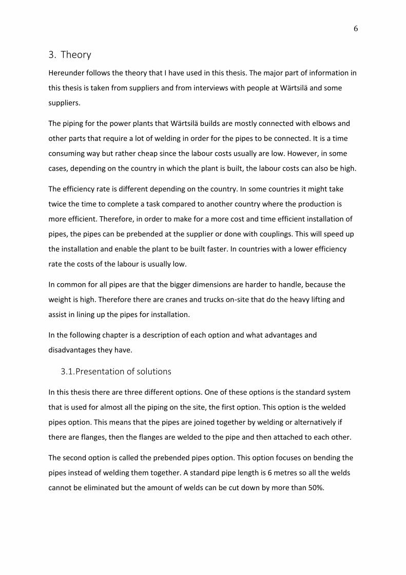
Figure 2. A welded pipe joint. (Morin u.d.) ................................................................................ 7
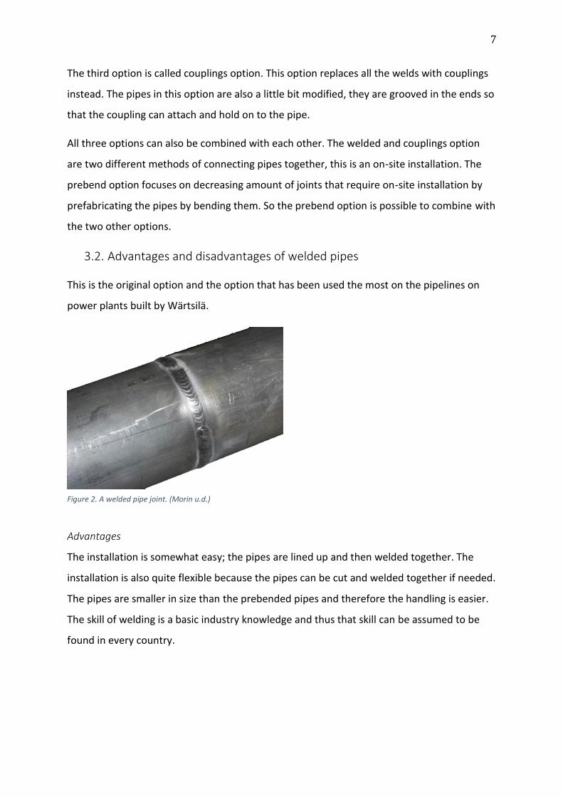
Figure 3. Prebended pipes. (Uwira u.d.) .................................................................................... 8
Figure 4. Coupling explained. (Quickcoup u.d.) ......................................................................... 9
Figure 5. Different bending measurements. (Own construction) ............................................ 16
Figure 6. Flare flange system. (GS-Hydro u.d.) ......................................................................... 26
LIST OF TABLES
Table 1. Container size ............................................................................................................. 12
Table 2. Cost comparison (Finland) .......................................................................................... 23
Table 3. Time comparison (Finland) ......................................................................................... 23
Table 4. Cost comparison (Country X) ...................................................................................... 24
Table 5. Time comparison (Country X) ..................................................................................... 24
APPENDICES
Appendix 1. Matrix for comparison
TERMS AND ABBREVIATIONS
RFQ – Request for quotation
EPC – Engineering, procurement and construction
SAP – Systems, Applications & Products in Data Processing
Fast track – fast delivery of a ready to launch power plant
TEU – Twenty foot equivalent unit
AWWA – American Water Works Association
WIMCE – cost and time estimation programme
DN – Diamètre nominal/nominal diameter
1
1. Introduction
Hereunder follows an introduction to the thesis with its objective, delimitations, research plan and
the structure for the thesis.
1.1. Purpose
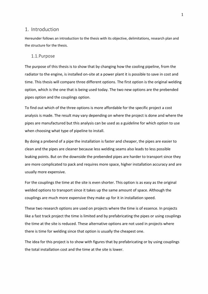
The purpose of this thesis is to show that by changing how the cooling pipeline, from the
radiator to the engine, is installed on-site at a power plant it is possible to save in cost and
time. This thesis will compare three different options. The first option is the original welding
option, which is the one that is being used today. The two new options are the prebended
pipes option and the couplings option.
To find out which of the three options is more affordable for the specific project a cost
analysis is made. The result may vary depending on where the project is done and where the
pipes are manufactured but this analysis can be used as a guideline for which option to use
when choosing what type of pipeline to install.
By doing a prebend of a pipe the installation is faster and cheaper, the pipes are easier to
clean and the pipes are cleaner because less welding seams also leads to less possible
leaking points. But on the downside the prebended pipes are harder to transport since they
are more complicated to pack and requires more space, higher installation accuracy and are
usually more expensive.
For the couplings the time at the site is even shorter. This option is as easy as the original
welded options to transport since it takes up the same amount of space. Although the
couplings are much more expensive they make up for it in installation speed.
These two research options are used on projects where the time is of essence. In projects
like a fast track project the time is limited and by prefabricating the pipes or using couplings
the time at the site is reduced. These alternative options are not used in projects where
there is time for welding since that option is usually the cheapest one.
The idea for this project is to show with figures that by prefabricating or by using couplings
the total installation cost and the time at the site is lower.
2
1.2. Delimitation
This thesis is limited to one project, for which the cost comparison has been done. The result
of this thesis can then be applied to other projects where the similar options apply. The
numbers that have been used in this research originate from quotations from suppliers of
the different pipe components. These prices can vary depending on the supplier, but it is
important that the quoted pipes have the same standard and requirements as the pipes
quoted for in this thesis. All the calculations are made based on one engine, so depending on
how many engines the power plant is having, the price has to be roughly multiplied with the
amount of engines in the installation. The amount of pipe meters will probably also change
since some of the pipelines differ from other, depending on the placement of the engine
along with the specific pipeline price for each engine.
1.3. Research plan
To achieve a good result in this thesis I intend to take information from a wide array of
sources. I am going to conduct interviews to get information for the three different options
and for the prices quotations will be sent to suppliers using the database that Wärtsilä has.
The result of these methods is displayed in a matrix and excel sheets where the options can
be compared to each other, enabling a decision that is most preferred for the project.
1.4. Thesis structure
In the second chapter I will present Wärtsilä, the company for which I have done my thesis.
The third chapter contains all the theory that I have based all my conclusions and
calculations on.
Fourth chapter is the method, which shows how I have done my research to acquire results.
In the fifth chapter is where I present the results of this thesis.
The sixth chapter contains the conclusion and the summary of my thesis.
3
2. The Company
Wärtsilä is a company, which originates from Finland but is spread across the world. The
company has a history stretching back for 180 years, starting from a small sawmill in
Tohmajärvi. Nowadays Wärtsilä is split into three sections; Ship Power, Services and Power
Plants. (Wärtsilä u.d.)
2.1. Wärtsilä in brief
According to Wärtsilä, Ship Power has their focus on the marine market. They provide
solutions for ships including machinery, propulsion and manoeuvring. The products they
deliver are engines and generating sets, reduction gears, propulsion equipment's, control
systems and sealing solutions both for vessels and offshore applications.
Services support Power Plants and Ship Power installations with solutions for the service and
running of the equipment including training. Wärtsilä has also extended its service to other
engine brands. Service provides of course maintenance for all Wärtsilä products.
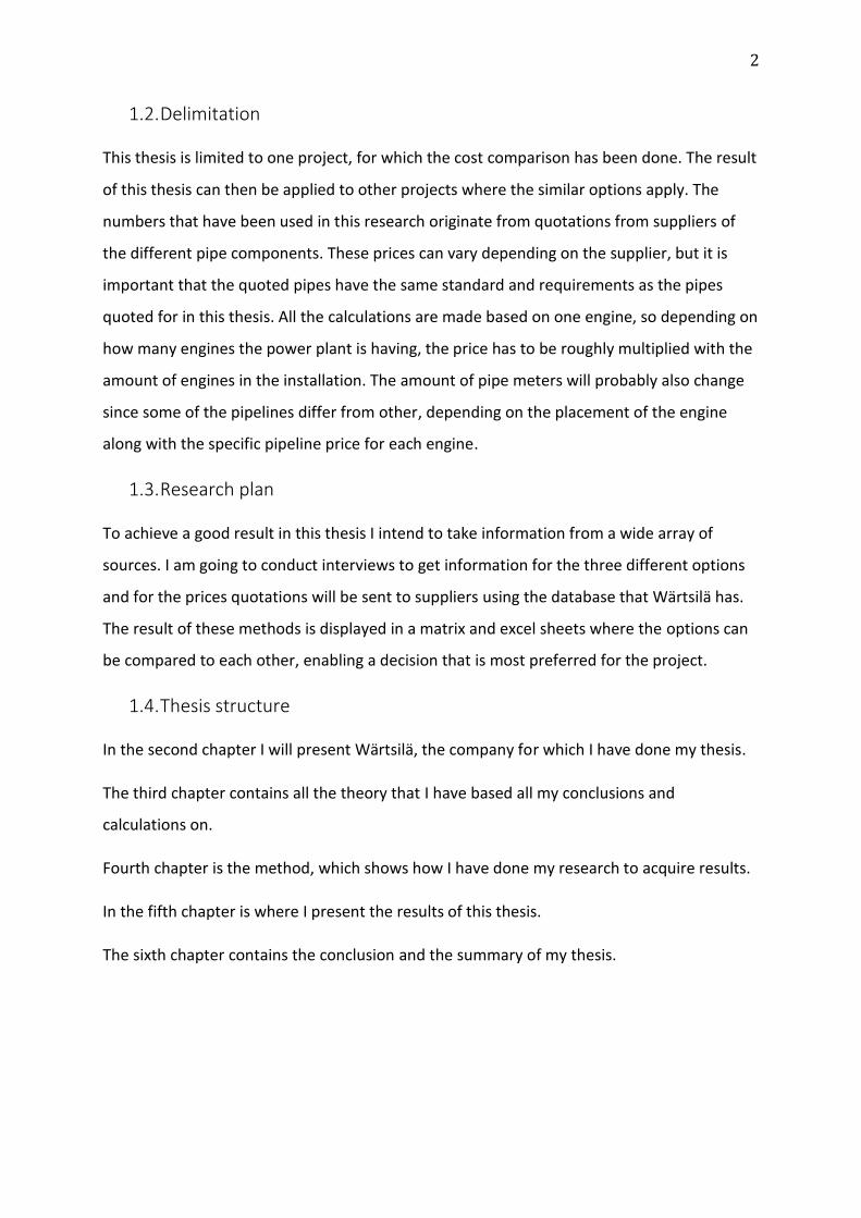
Figure 1. Wärtsilä corporation structure (Wärtsilä u.d.)
4
2.2. Power Plants
Wärtsilä Power Plants is a part of the Wärtsilä Corporation, which also contains Ship Power
and Services. Wärtsilä is a global leader in both the flexible base load power plant and
marine market.
In the year of 2014 Wärtsilä had a total capacity of 55 GW of installed power plants around
the globe. The power plants are located in 169 different countries. Power Plants offer three
different power solutions: peaking, reserve and load-following power.
The strengths for Wärtsilä’s power plants are flexible design, high efficiency and low
emission levels. Power Plants had a total NET sale of 1,138 million Euros for the year of 2014
and a total personnel of 978.
Wärtsilä Power Plants has been developed under several generations. They are more reliable
and more efficient than large power stations. The engines are excellent at adapting to power
peaks. The power plants have multiple modes and can be used as a dynamic complement
system to wind or solar power.
Several of the power plants are multi-fuel. Meaning that they can use different kinds of
fuels, both liquid and gas, depending on what is more optimal. By doing so the power plants
are able to be more feasible for the future where the use of natural gas is expected to grow.
The power plants are also small in size, which enables the placing of them on critical load
pockets, like in cities. Also the plants are low in emissions and noise levels, which makes
them suitable for placement close to population. (Wärtsilä u.d.)
2.3. EPC Project
EPC stands for Engineering, Procurement and Construction. An EPC project is a project
where the seller does all the work and basically hands over the keys to the buyer and then
everything is good to go.
In an EPC project the importance is on planning and the right cost estimation so that the
quotation of the project is done right and the seller makes profit from the project.
By purchasing an EPC project the customer does not need to interfere in the building of the
construction, or any other factor.
5
This cost comparison is only applicable for projects where Wärtsilä also is in charge of
building the power plant. (Project Auditors u.d.)
6
3. Theory
Hereunder follows the theory that I have used in this thesis. The major part of information in
this thesis is taken from suppliers and from interviews with people at Wärtsilä and some
suppliers.
The piping for the power plants that Wärtsilä builds are mostly connected with elbows and
other parts that require a lot of welding in order for the pipes to be connected. It is a time
consuming way but rather cheap since the labour costs usually are low. However, in some
cases, depending on the country in which the plant is built, the labour costs can also be high.
The efficiency rate is different depending on the country. In some countries it might take
twice the time to complete a task compared to another country where the production is
more efficient. Therefore, in order to make for a more cost and time efficient installation of
pipes, the pipes can be prebended at the supplier or done with couplings. This will speed up
the installation and enable the plant to be built faster. In countries with a lower efficiency
rate the costs of the labour is usually low.
In common for all pipes are that the bigger dimensions are harder to handle, because the
weight is high. Therefore there are cranes and trucks on-site that do the heavy lifting and
assist in lining up the pipes for installation.
In the following chapter is a description of each option and what advantages and
disadvantages they have.
3.1. Presentation of solutions
In this thesis there are three different options. One of these options is the standard system
that is used for almost all the piping on the site, the first option. This option is the welded
pipes option. This means that the pipes are joined together by welding or alternatively if
there are flanges, then the flanges are welded to the pipe and then attached to each other.
The second option is called the prebended pipes option. This option focuses on bending the
pipes instead of welding them together. A standard pipe length is 6 metres so all the welds
cannot be eliminated but the amount of welds can be cut down by more than 50%.
7
The third option is called couplings option. This option replaces all the welds with couplings
instead. The pipes in this option are also a little bit modified, they are grooved in the ends so
that the coupling can attach and hold on to the pipe.
All three options can also be combined with each other. The welded and couplings option
are two different methods of connecting pipes together, this is an on-site installation. The
prebend option focuses on decreasing amount of joints that require on-site installation by
prefabricating the pipes by bending them. So the prebend option is possible to combine with
the two other options.
3.2. Advantages and disadvantages of welded pipes
This is the original option and the option that has been used the most on the pipelines on
power plants built by Wärtsilä.
Advantages
The installation is somewhat easy; the pipes are lined up and then welded together. The
installation is also quite flexible because the pipes can be cut and welded together if needed.
The pipes are smaller in size than the prebended pipes and therefore the handling is easier.
The skill of welding is a basic industry knowledge and thus that skill can be assumed to be
found in every country.
Figure 2. A welded pipe joint. (Morin u.d.)
8
Disadvantages
Installation of a line with several welded seams takes time. One seam on a pipe can take up
to several hours to weld. The welding seams require a lot of cleaning in order to not
contaminate the pipe line and cause a malfunction of the system. (Mäki-Reini 2015)
3.3. Advantages and disadvantages of prebended pipes
Below follows a more detailed view of the benefits of a prebended pipe design and what
disadvantages also occurs when the pipe is prebended.
Advantages
Wärtsilä have done prebending on projects where the time and money has been of greater
importance, such as projects with short delivery time and when the labour costs for the site
have been high.
Prebended pipes also require some welding but a lot less compared to normal pipe design.
By prebending there are also several other benefits that can be taken into consideration.
By prebending the pipes instead of welding them together there will be less welding seams,
which make them cleaner compared to if they would have been welded.
The pipe doesn't need as much cleaning, less seams means the pipe is kept cleaner. Also by
having fewer seams the chance of a leakage is lower. By having a faster installation time the
installation will be cheaper.
Disadvantages
From production to the site the logistics of the pipe is more demanding. The pipes take up
more space and require more planning when they are packed for transportation. When the
Figure 3. Prebended pipes. (Uwira u.d.)

9
pipes are prebended they also require better accuracy when they are installed. The pipe
code needs to be written down on the pipe for clarification and to reduce the risk of
mistakes.
A prebended pipe is also fitted for the design. This means that if the design needs to be
altered, the pipe will be more likely not to fit in in the new system where a normal pipe
would be more flexible. However, the risk of a change of order is small. The prebended pipe
is also heavier, since there is only one pipe instead of two pipes, as it would be in the two
other options, making the handling of the pipe more difficult.
Lastly the price for the production of the pipe is higher. (Kuusisto, Re-routing of cooling
water pipeline 2011) (Björk 2015)
3.4. Advantages and disadvantages of couplings
Hereunder follows a more detailed view of the benefits of a coupling pipe design and what
disadvantages also occurs when the design is done with couplings. In case that the
contractor does not have the knowledge on how the couplings should be installed there is a
possibility to receive a half a day training to learn how to install the couplings correctly. This
training is done with a video clip. This option is used on firefighting equipment. On the
smaller dimensions of the couplings design the couplings are not applied, the pipes are
welded instead.
Figure 4. Coupling explained. (Quickcoup u.d.)
10
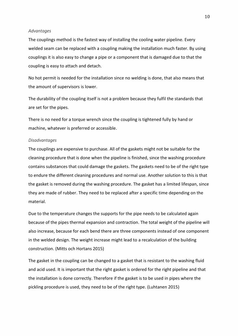
Advantages
The couplings method is the fastest way of installing the cooling water pipeline. Every
welded seam can be replaced with a coupling making the installation much faster. By using
couplings it is also easy to change a pipe or a component that is damaged due to that the
coupling is easy to attach and detach.
No hot permit is needed for the installation since no welding is done, that also means that
the amount of supervisors is lower.
The durability of the coupling itself is not a problem because they fulfil the standards that
are set for the pipes.
There is no need for a torque wrench since the coupling is tightened fully by hand or
machine, whatever is preferred or accessible.
Disadvantages
The couplings are expensive to purchase. All of the gaskets might not be suitable for the
cleaning procedure that is done when the pipeline is finished, since the washing procedure
contains substances that could damage the gaskets. The gaskets need to be of the right type
to endure the different cleaning procedures and normal use. Another solution to this is that
the gasket is removed during the washing procedure. The gasket has a limited lifespan, since
they are made of rubber. They need to be replaced after a specific time depending on the
material.
Due to the temperature changes the supports for the pipe needs to be calculated again
because of the pipes thermal expansion and contraction. The total weight of the pipeline will
also increase, because for each bend there are three components instead of one component
in the welded design. The weight increase might lead to a recalculation of the building
construction. (Mitts och Hortans 2015)
The gasket in the coupling can be changed to a gasket that is resistant to the washing fluid
and acid used. It is important that the right gasket is ordered for the right pipeline and that
the installation is done correctly. Therefore if the gasket is to be used in pipes where the
pickling procedure is used, they need to be of the right type. (Luhtanen 2015)
11
3.5. Requesting for a quotation
In this thesis the comparison is done based on the quotations that is received from supplier.
Therefore it is of importance that the supplier knows what to include in the quotation.
The RFQ should be as detailed as possible without revealing business secrets. The more
details given to the supplier the more information he can use to give a more reliable
quotation. Depending on how well you know the supplier you can give different amount of
information. There can be suppliers you have done business with during several years as well
as the new and untested supplier and thus the amount of information given should be
considered.
The information given should contain the following:
Specification sheets
Additional technical drawings and pictures, if needed
Sizes and dimensions
Material specifications
Packing requirements, if packing is done by supplier
Quality documentation
When dealing with a long-term supplier the information given would logically be increased
due to ease in production and delivery for the supplier. If there is a large annual order
volume from the same supplier you could negotiate better prices.
If you are looking for completely new suppliers you should never settle for only one
quotation. At least three quotations should be answered so that you can get the most
beneficial order.
When a new supplier has been established, good communication and cooperation is a key to
a successful relationship.
When receiving a quotation, it is important to go through it so that all the details are correct
and that there are no hidden fees. (China Performance Group u.d.) (Geoffrey 2014)
12
3.6. Packing and installation procedure
All the pipes are packed into containers at the supplier. Depending on what design that is
packed, there might be different amounts of containers needed for all the components. This
because the prebend design can take up to double the amount of space when packed. Also
for the couplings option there are a little more components packed.
For the prebended pipes each order is a little different from the other. This is because there
is no standard of how to pack the prebended pipes. That means that each time an order of
prebended pipes are packed, the supplier spreads all the pipes out on the floor and then
figures out how the pipes will be packed into the container. A factor that can make this
packing procedure even harder is if the pipes are done in a three-dimensional plane,
meaning that they have bends that stretch out of the two-dimensional plane. The supplier
prefers that all the pipes be bent only in a two-dimensional plane, however, several bends
can occur on the same pipe. (Lammi 2015)
For the couplings there are a little more components packed compared to the original
option, because for each elbow that would otherwise be welded there are two couplings
needed. Included in the container is also two grooving machines, one that is driven by hand
and the other that is driven by electricity. (Mitts och Hortans 2015)
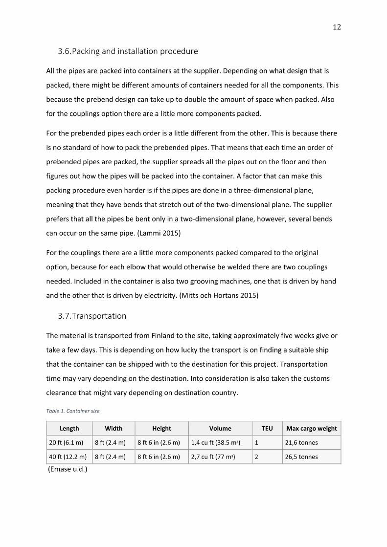
3.7. Transportation
The material is transported from Finland to the site, taking approximately five weeks give or
take a few days. This is depending on how lucky the transport is on finding a suitable ship
that the container can be shipped with to the destination for this project. Transportation
time may vary depending on the destination. Into consideration is also taken the customs
clearance that might vary depending on destination country.
Table 1. Container size
Length Width Height Volume TEU Max cargo weight
20 ft (6.1 m) 8 ft (2.4 m) 8 ft 6 in (2.6 m) 1,4 cu ft (38.5 m3) 1 21,6 tonnes
40 ft (12.2 m) 8 ft (2.4 m) 8 ft 6 in (2.6 m) 2,7 cu ft (77 m3) 2 26,5 tonnes
(Emase u.d.)
13
As can be seen in table 1 above the maximum weight does not differ so much from the 20
feet to the 40 feet container even if the volume is almost double the amount in the 40 feet
container. There are also other containers with similar size that allows more cargo weight,
but that is not needed for the pipes. The price difference between these solutions is almost
the same as the difference in cargo weight, making it much more valuable to use one 40 foot
container instead of two 20 foot containers. Assuming that the amount of normal piping
would fit into a 20-foot container, the prebended design would fit into a 40-foot container.
This means that the price to transport the prebended option is not double the normal cost
because the volume is doubled. The cost, for Wärtsilä, to transport a 40-foot container from
Finland to Senegal compared to a 20-foot container is only 35% more for the 40-foot
container.
When planning the time consumption for transporting the container across continents the
only a rough estimation can be made. Time spent on the sea transport and customs
clearance is a thing that influences the transportation time. They are factors that are more
or less hard to affect, however, the right documentation eases the customs clearance but
problems can still occur. (Granberg 2015)
During the transportation it is important to keep the pipes clean and dry. Moist and dirt
could get into the container. In order to protect the pipes from rust and other contamination
they are greased and a plug is inserted in both ends of the pipe. (Lammi 2015)
Wärtsilä has of course discount prices because they are a frequent transporter.
3.8. Importance of choosing the right supplier
When choosing a supplier Wärtsilä have criteria's that the supplier most fulfil. Wärtsilä has a
Suppliers Handbook with information and requirements that they demand from each
supplier. Depending on each department there might be specific things that are taken into
consideration when choosing the supplier. For the cooling water pipes there are some things
that need to be taken into account when choosing the supplier for the pipes and
components.
14
It is preferable that the supplier supplies all the components that are included in the order to
make the handling of the order easier and minimizing the risk that a part of that order would
be delayed.
3.9. Weight differences between options
In the case that there is a change in pipe design there is probably also a change of weight for
the pipes. The couplings option is heavier than the original welding option since, instead of
one component that will connect the pipes, there are three components that connect them,
two couplings and one elbow component, this leads to a weight increase.
For the prebended option the weight is going to decrease compared to the couplings option,
since there is no pipe component, just a pipe that is bent. Se calculation below.
If the radiators are on the roof the weight on the roof will increase if the coupling option is
used. Therefore the strength of the roof might need recalculation. In some cases the building
could be reinforced, but in case the increase is minimal and the maximum allowed weight is
not exceeded no further modification is required.
Below is an example for one bend, prebended option compared to the coupling option.
DN200, prebended = normal pipe weight for the distance that the pipe is bent.
DN200 bend length is 438mm (Uwira u.d.), weight for 1000mm is 23,80 kg (Wärtsilä
u.d.)
Then the weight for one bend is 10,42 kg
DN200, coupling = one joint/bend requires two couplings and a component (e.g. elbow).
2x DN200 Coupling weight = 3,83 kg
DN200 Elbow weight = 9,92 kg
Total weight for coupling joint is 17,58 kg (LVI-Dahl u.d.)
Weight difference between these two options for one bend is around 7 kg for DN200 pipes.
As a result the prebended option is lighter than the original option and the couplings option
is slightly heavier than the original option, which is 16 kg (Onninen u.d.).
15
3.9.1. For welded pipes
When choosing the supplier of the welded pipes there is not so much to take into
consideration other than that every pipe must fulfil all the standards and that the supplier
can provide all the parts for the order.
3.9.2. For prebended pipes
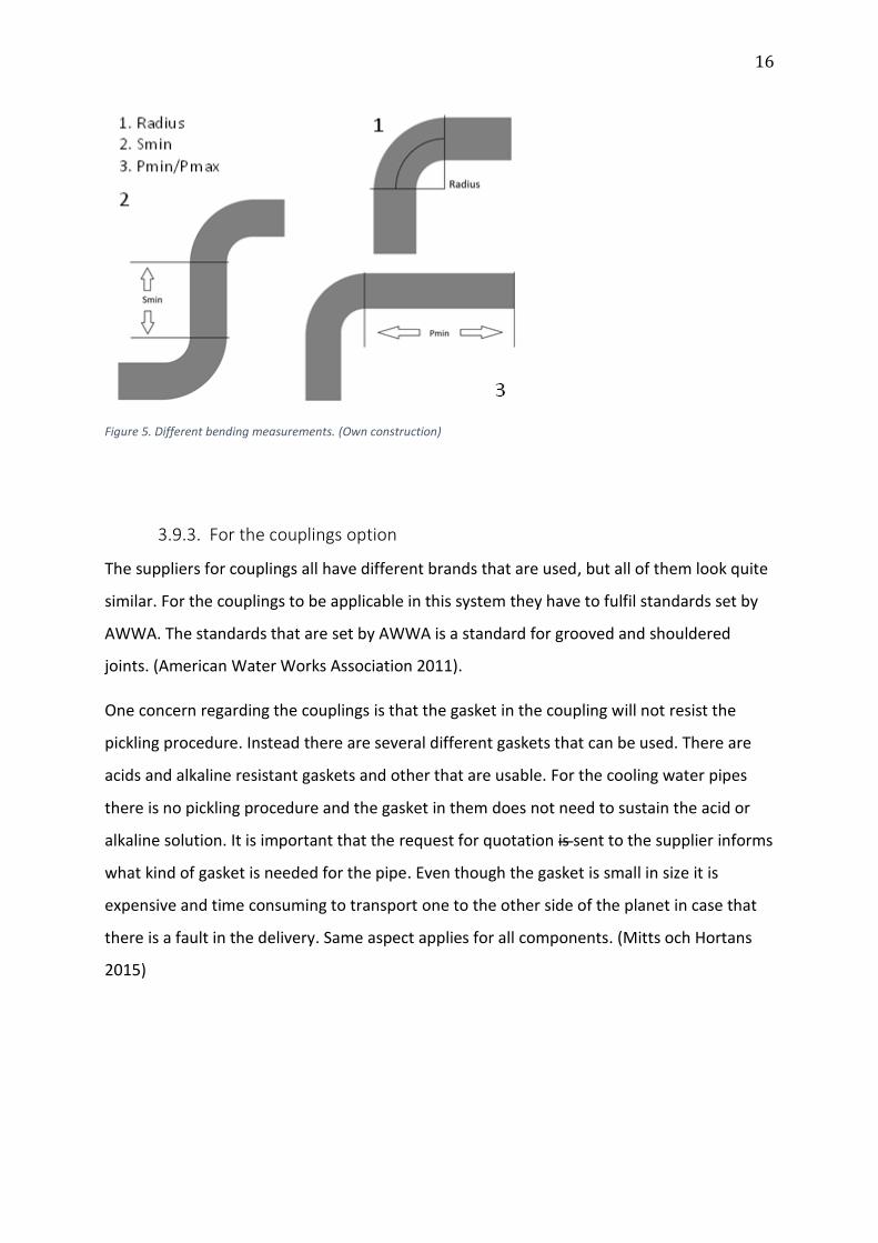
For the prebended pipes there are a four factors influencing on the pipe when it is bent.
The first thing that is of most importance is the bending radius, since there are several
different pipe dimensions in one design. The radius on the bend is depending on the
machine model that the suppliers have. The suppliers have different machines that they are
using and each machine model have a bending radius of their own. Therefore the design
needs to be custom made to a certain level, depending on the manufacturer. It is considered
that the lower the bending radius the better, since less space is needed for the bend.
For the pipe there is also a Smin, a Pmin and a Pmax value. The Smin value means the
minimum value in millimetres that it needs to be in-between two bends in order for the
machine to work if there are more than two bends on a single pipe. The Pmin and Pmax
value means the minimum and maximum value in millimetres that is needed on one of the
sides of the bend so that the machine can bend the pipe. In case the pipe need to be shorter,
the pipe can be cut after it has been bent in the machine. The standard pipe length for a
DN200 pipe is 600 mm so it is preferable that the whole pipe fits into the machine in order
to minimize the waste materials. If there is waste material those pipes are sent together
with the rest of the material in the container to and can be used on-site if they are needed.
Lastly there is the thickness of the pipe wall. The thicker it is the more pressure it can hold
and the more it can be bent. However, with a thicker pipe wall the more force is needed to
bend the pipe. Due to this, the bending machines at the supplier are a major factor for the
pipe manufacturing and specifications. (Grönkvist 2015) (Uwira u.d.)
An explanation to how the pipes are measured can be seen in figure 5.
16
3.9.3. For the couplings option
The suppliers for couplings all have different brands that are used, but all of them look quite
similar. For the couplings to be applicable in this system they have to fulfil standards set by
AWWA. The standards that are set by AWWA is a standard for grooved and shouldered
joints. (American Water Works Association 2011).
One concern regarding the couplings is that the gasket in the coupling will not resist the
pickling procedure. Instead there are several different gaskets that can be used. There are
acids and alkaline resistant gaskets and other that are usable. For the cooling water pipes
there is no pickling procedure and the gasket in them does not need to sustain the acid or
alkaline solution. It is important that the request for quotation is sent to the supplier informs
what kind of gasket is needed for the pipe. Even though the gasket is small in size it is
expensive and time consuming to transport one to the other side of the planet in case that
there is a fault in the delivery. Same aspect applies for all components. (Mitts och Hortans
2015)
Figure 5. Different bending measurements. (Own construction)
17
3.10. Installation procedure
In section 3.10 follows the procedure that is done when the pipeline is installed, from the
arrival of the container to the site until it is finalised and ready for operation. This installation
procedure is the same for all the options. The only difference is the joining method between
the welded option and the couplings option.
3.10.1. Installation
When the containers have arrived to the site and it is time for installation the parts are
unloaded and sorted out. If the pipes are prebended they are placed in groups, but all the
pipes are kept in the container until installation to protect them from dirt and damage. The
pipes are lined up and with the use of cranes or trucks the pipes are moved and lined up for
connection. The installation is done from two ends simultaneously, however, the method
may vary depending on the contractor. The two starting points are the engine and the
radiator; they meet up in the middle. For each option the same thing is done except the
joining method that is different depending on if the pipes are welded together or connected
with joints. The prebended option does not affect the way the pipes are connected, only the
amounts of joints that are needed for the pipeline to be complete.
This is done for each of the pipelines; there are two pipelines for each engine. In some cases
there are additional pipelines for each engine in case better efficiency of heat recovery is
preferred. When the pipeline is completely installed they are cleaned. (Kuusisto, Expert,
Performance and Technology 2015)
3.10.2. Cleaning
All the pipes that are installed on the plant are cleaned. Depending on what purpose they
serve they are cleaned differently. Some pipes demand more cleaning than others. In
common for all pipes are that they are cleaned from slag and rust by scaling with tools and
also grinding the welding seams, and that they are blown with compressed air. If the pipes
are greased they need to be washed with an alkaline solution with a water temperature of
80°C for degreasing. For cooling pipes there are four treatments that is done before the pipe
is ready for use.
In total there are six different cleaning methods that is used depending on what kind of
pipeline it is.

18
First the pipe is washed with the alkaline solution, this is only done if the pipe is greased.
Second treatment is removing of slag, rust and scaling with tools and grinding the welded
seams inside the pipe to receive a smooth surface and prevent contamination.
Thirdly the pipe is then blown with compressed air to remove any leftovers from inside the
pipe.
Lastly the pipe is treated by flushing it with water. (Wärtsilä 2014)
19
4. Method
For the specific information for this thesis I have interviewed people within Wärtsilä. For
each solution I have conducted interviews to achieve a good result where as much
information as possible is received. I also conducted Interviews to one of Wärtsilä's
subcontractor. To receive prices I have contacted Wärtsilä’s suppliers.
4.1. Interviews – qualitative research
The people I have interviewed have been pointed out by my supervisor. When I have had an
issue that I wanted to find out he named someone who knew more information about it.
Once or twice I got redirected to a second source. Questions asked during the interviews
were made in advance and were based on the topic for the interview. The interviews were
made both in person and over e-mail, whichever was easier to achieve. Language used when
performing the interviews was English, Swedish or Finnish depending on what was preferred
by the interview subject. The Wärtsilä personnel were quick and eager to answer my
questions and it seldom took more than one day for me to receive and answer on my
questions.
4.2. Quotations and prices
The prices I have used in this thesis originates from quotations from Wärtsilä's suppliers and
information within Wärtsilä for prices for work done by Wärtsilä personnel.
4.3. General comparison
In order to receive an exact time estimation from a contractor on-site there are several
factors that are taken into consideration and not only the time that it takes to weld one
seam. For all the options there are handling times, lining up times and installation times. I
have assumed the handling and lining up times are approximately the same for all the
options since the parts are similar in size. But it is on the installation time that time is saved
by using another option than the original welding option. Therefore the installation time and
the delivery time are the only timelines that are different depending on the option.
When Wärtsilä asks for a RFQ from the contractors, Wärtsilä gives out a form that describes
the amount of components, welds, pipe metres etc. in order for the contractor to quote for

20
the work that is needed. If there is a something that is not included in the quotation and that
needs to be done the contractor will do it but will charge extra as a change of order.
(Kivimäki 2015)
21
5. Results
In this chapter the result of this thesis is presented. A matrix where the prices are compared
and a matrix where the time is compared has also been made. These are confidential and
therefore a modified comparison is shown in this chapter and the matrix is shown in the
appendix. The matrix is a clarification tool to show the differences between the options. For
Wärtsilä the results have been handed over in the form of an excel file. The excel file
contains several sheets to show how the calculations have been done.
5.1. Confidentiality
Since the numbers that I have acquired are current and used by Wärtsilä, they are
considered confidential. Both the prices and the time consumption for the project are
confidential. To show the differences between the different options I have decided that the
easiest way to express the values is in percentages.
Wärtsilä have annual agreements with their suppliers, which means that they have a
discounted price when ordering from them. This discount is received because the volume
that Wärtsilä orders is so big so the profit margin for the supplier doesn’t need to be as high
as if they would sell to a smaller company that purchases a lower volume each year.
The labour times that I have received are confidential because they show the time table for a
project.
5.2. Comparison
Of these conclusions it can be stated that there are possibilities to save money by using the
prebend or the couplings option instead of the welded option. There are also possibilities to
combine the two solutions so that the amount of joints are minimized by prebending and
then the joints that are left are connected by couplings, thus leading to a much lower
installation time on-site.
The difference in price is shown as if the welded option would be 100 % and the other two
options are shown as a percentage of that, e.g. 75 % means that the cost is 75 % of 100 %.
This means that if the welded cost is 100 euros the 75 % option is 75 euros.

22
For the cost from the supplier it is assumed that they charge for the material and the packing
of the material and that Wärtsilä will purchase the containers. The contractor price is
calculated from Finnish hourly rates.
Hereunder follows two tables with the cost and time comparison of the different options,
the difference is shown in percentages compared to the welded option, since the real figures
are confidential.
23
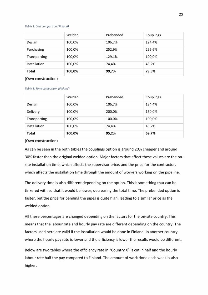
Table 2. Cost comparison (Finland)
Welded Prebended Couplings
Design 100,0% 106,7% 124,4%
Purchasing 100,0% 252,9% 296,6%
Transporting 100,0% 129,1% 100,0%
Installation 100,0% 74,4% 43,2%
Total 100,0% 99,7% 79,5%
(Own construction)
Table 3. Time comparison (Finland)
Welded Prebended Couplings
Design 100,0% 106,7% 124,4%
Delivery 100,0% 200,0% 150,0%
Transporting 100,0% 100,0% 100,0%
Installation 100,0% 74,4% 43,2%
Total 100,0% 95,2% 69,7%
(Own construction)
As can be seen in the both tables the couplings option is around 20% cheaper and around
30% faster than the original welded option. Major factors that affect these values are the on-
site installation time, which affects the supervisor price, and the price for the contractor,
which affects the installation time through the amount of workers working on the pipeline.
The delivery time is also different depending on the option. This is something that can be
tinkered with so that it would be lower, decreasing the total time. The prebended option is
faster, but the price for bending the pipes is quite high, leading to a similar price as the
welded option.
All these percentages are changed depending on the factors for the on-site country. This
means that the labour rate and hourly pay rate are different depending on the country. The
factors used here are valid if the installation would be done in Finland. In another country
where the hourly pay rate is lower and the efficiency is lower the results would be different.
Below are two tables where the efficiency rate in “Country X” is cut in half and the hourly
labour rate half the pay compared to Finland. The amount of work done each week is also
higher.
24
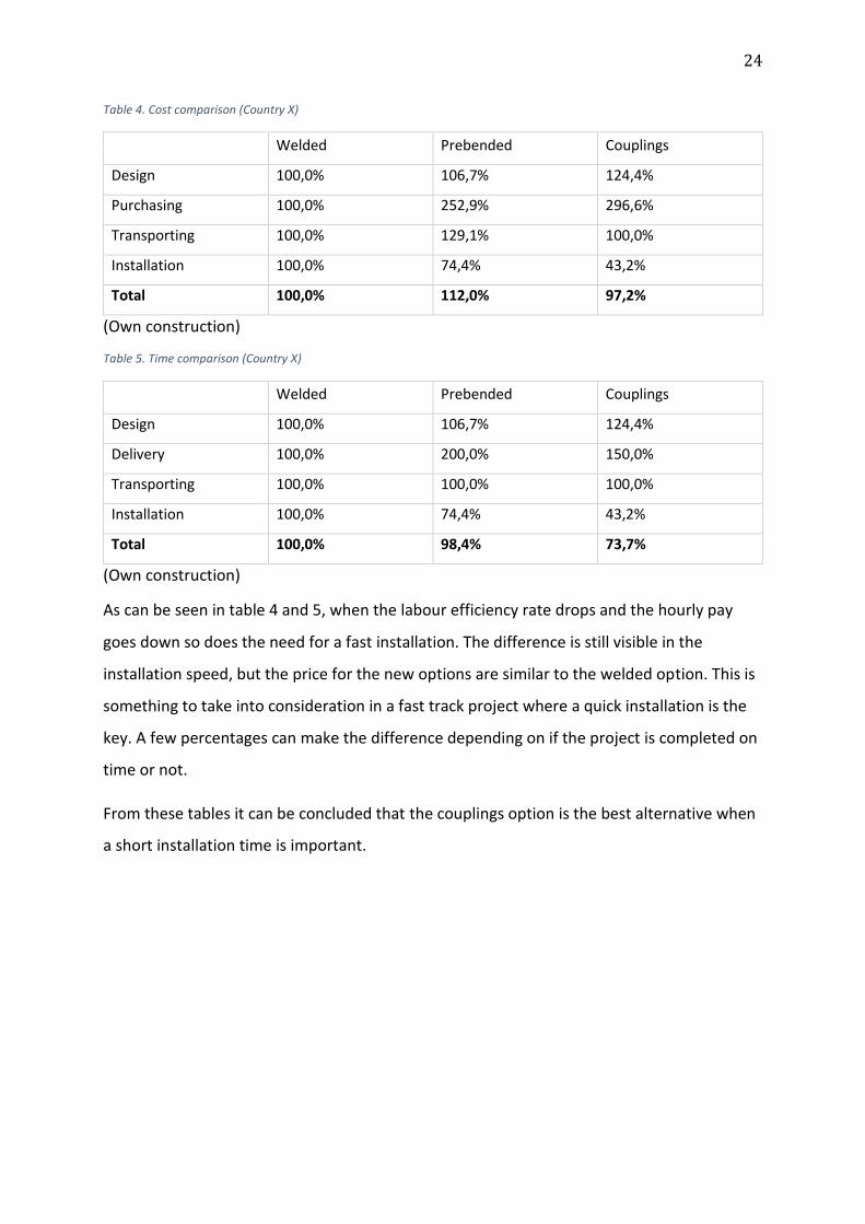
Table 4. Cost comparison (Country X)
Welded Prebended Couplings
Design 100,0% 106,7% 124,4%
Purchasing 100,0% 252,9% 296,6%
Transporting 100,0% 129,1% 100,0%
Installation 100,0% 74,4% 43,2%
Total 100,0% 112,0% 97,2%
(Own construction)
Table 5. Time comparison (Country X)
Welded Prebended Couplings
Design 100,0% 106,7% 124,4%
Delivery 100,0% 200,0% 150,0%
Transporting 100,0% 100,0% 100,0%
Installation 100,0% 74,4% 43,2%
Total 100,0% 98,4% 73,7%
(Own construction)
As can be seen in table 4 and 5, when the labour efficiency rate drops and the hourly pay
goes down so does the need for a fast installation. The difference is still visible in the
installation speed, but the price for the new options are similar to the welded option. This is
something to take into consideration in a fast track project where a quick installation is the
key. A few percentages can make the difference depending on if the project is completed on
time or not.
From these tables it can be concluded that the couplings option is the best alternative when
a short installation time is important.
25
6. Conclusion
In this chapter follows the conclusion and what the following steps, such as further research,
would be.
6.1. Summary
In this thesis I have compared three different solutions, one that is in use, and to new ones
that are to be implemented and used on projects where the on-site installation time is
crucial to be short. The options compared to each other were the welded option, the
prebended option and the couplings option.
The difference for purchasing the different options was big, the welded option being the
cheapest and the couplings option the most expensive. Then there was the transportation of
the parts from the supplier to the site, where the installation is done. The prebended option
takes up to twice the amount of volume when they are packed, because of the bends on the
pipe making it difficult to pack.
The options have been compared to each other in order to see which one of them have the
fastest on-site installation time and which one of them are the most economical. From the
cost and time calculation it can be concluded that by using the couplings option it is possible
to save on site costs and time.
In the end there were also additional new options that emerged and could be used alongside
the prebend and couplings options in order to make the design even more efficient.
Even though the welded option is the least favourable and welding is the most time
consuming way of joining two pipes, it is hard to completely eliminate the welds, since some
welding is always needed.
6.2. Problems
In order to achieve a very exact cost comparison between all the options a lot of factors
would have been needed to take into consideration. I have done the comparison by
comparing a few parts in each solution to each other. Regarding the differences in the
installation for the options, I have assumed that the time and handling cost on-site have
been the same for each option when comparing the biggest difference in installation time.
26
Another thing that might change the result are the prices from the suppliers; each quotation
had a final date when the price I received was viable. This means that next time a quotations
is asked for the price might differ from the one I received. A challenge in this thesis was also
to keep down the amount of factors taken into consideration in the cost comparison; factors
that did not influence the comparison too much were not taken into consideration.
6.3. Further research
For further research the possibilities to implement prebended and/or coupling options on
other pipelines could be investigated. It is proven that time could be saved by changing to
either one of these options, time that is valuable when there is a deadline for when the plant
must be operational and produce electricity.
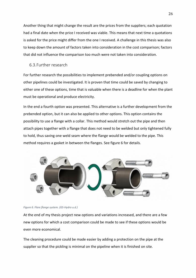
In the end a fourth option was presented. This alternative is a further development from the
prebended option, but it can also be applied to other options. This option contains the
possibility to use a flange with a collar. This method would stretch out the pipe and then
attach pipes together with a flange that does not need to be welded but only tightened fully
to hold, thus saving one weld seam where the flange would be welded to the pipe. This
method requires a gasket in between the flanges. See figure 6 for details.
Figure 6. Flare flange system. (GS-Hydro u.d.)
At the end of my thesis project new options and variations increased, and there are a few
new options for which a cost comparison could be made to see if these options would be
even more economical.
The cleaning procedure could be made easier by adding a protection on the pipe at the
supplier so that the pickling is minimal on the pipeline when it is finished on site.

27
When choosing a contractor to build the power plant, it should be preferred that they have
the skill to bend pipes with a small dimension, e.g. sizes below DN50, in order to save in on
welds.
6.4. Economic impact
In order to save time on the site installation and thus saving money, money must first be
spent in prefabricating pipes or procuring components that are fast to install but expensive
to purchase. This would lead to a higher cost and slightly longer production time in the
beginning but would save installation time in the end, hence saving money and time on-site.
The possibilities to change the way the pipe is installed are many and the possibilities to save
on installation costs on-site are big. All the calculations that I have done can also be made in
WIMCE when all the parts and information is entered into the system.
As seen in the tables the difference on location is a key to where each option is most
valuable. A high priced option is fast to install, but there is a threshold when it is no longer
beneficial to have a high installation speed. The costs of a plant being delayed from
operation are huge so if the time is important then the coupling option is the best option.
Costs are not only measurable in money, but also in credibility. By using couplings the
installation time is shortened by 30 % and costs are cut down by 20 % if the installation
would be done here in Finland. Abroad the cost difference is decreased in countries where
the labour costs are lower, but the time difference is not affected. Therefore by using
couplings the installation time is lowered.
6.5. Final conclusion
As a thesis this task was good. I had time to familiarize myself with the task, which felt hard
to grasp in the beginning but as time went by I learned more about the task and my
confidence grew stronger. Since this was my first work experience at Wärtsilä there was also
a lot of new information to take in, such as how the workplace functioned. In my opinion I
have learned it well. I have been in contact with a lot of different people within the company
when gathering information and this has been rewarding seeing how the system works. The
importance of delimitations is something that I have learned to respect. If my thesis would
not have been limited at all, the workload would have been huge.

28
I would like to thank my supervisors Mikael Ehrs at Novia University of Applied Sciences and
Peter Bergqvist at Wärtsilä for their support. I would also like to thank the people who have
helped me and answered my questions when I have been gathering information.
29
7. References
American Water Works Association. 2011. awwa.org. Accessed April 17, 2015.
http://www.awwa.org/store/productdetail.aspx?productId=6880.
Björk, Jan-Olof, interview by Svante Lindholm. 2015. “Interview regarding prebended pipes.”
Senior Chief Project Engineer. (19 march).
China Performance Group. n.d. 3 tips to get the right quote for your request of quotation.
Accessed March 20, 2015. http://www.chinaperformancegroup.com/2012/09/3-tips-
to-get-the-righte-quote-for-your-request-for-quotation-rfq/.
Emase. n.d. Shipping containers. Accessed March 31, 2015.
http://web.archive.org/web/20090420143514/http://emase.co.uk/data/cont.html.
Geoffrey, James. 2014. The Tricky Business of Giving Price Quotes . 27 March. Accessed April
15, 2015. http://www.inc.com/geoffrey-james/how-to-handle-request-for-price-
quote.html.
Granberg, Glenn, interview by Svante Lindholm. 2015. “Transportation time and costs.”
Coordinator. (26 March).
Grönkvist, Alf, interview by Svante Lindholm. 2015. “Prebending of pipes and design.” Cheif
Design Engineer. (6 March).
GS-Hydro. n.d. “GS-90° Flare flange system.” Accessed April 20, 2015.
http://www.gshydro.com/gs-hydro-products/gs-90deg-flare-flange-system.
Kivimäki, Timo, interview by Svante Lindholm. 2015. “On site costs and installations.” Senior
Installation Cost Estimator. (9 April).
Kuusisto, Tuomas, interview by Svante Lindholm. 2015. Expert, Performance and Technology.
(23 April).
Kuusisto, Tuomas. 2011. Re-routing of cooling water pipeline. Thesis, Vaasan
Ammattikorkeakoulu, Vaasa: Vaasan Ammattikorkeakoulu. Accessed March 2, 2015.
http://theseus.fi/handle/10024/26109.
Lammi, Otto, interview by Svante Lindholm. 2015. Quotation of prebended pipes (7 April).
30
Luhtanen, Pekka, interview by Svante Lindholm. 2015. “Durability of gaskets.” Development
Engineer. (1 April).
LVI-Dahl. n.d. Uraliittimet ja -osat. Accessed April 6, 2015. http://www.lvi-
dahl.fi/tuotteet/kategoria/teollisuus-uraliittimet-ja-osat-6130/#content.
Mäki-Reini, Raimo, interview by Svante Lindholm. 2015. “Properties for welded pipes.”
Inspection Manager. (7 April).
Mitts, Andreas, and Anders Hortans, interview by Svante Lindholm. 2015. Interview
regarding couplings (20 March).
Morin, Kevin. n.d. “Buttweld.” Accessed April 15, 2015.
http://s383.photobucket.com/user/kevinmorin_photo/media/24%20Open/controlsc
onduit_buttweld_2a.jpg.html.
Onninen. n.d. “Quote for pipes.” Accessed March 3, 2015.
Project Auditors. n.d. EPC Project. Accessed March 20, 2015.
http://www.projectauditors.com/Dictionary2/1.8/index.php/term/,62555a9cae535f
6f68555aaf5d5c5f.xhtml.
Quickcoup. n.d. “Grooved Coupling.” Accessed April 13, 2015.
http://www.quikcoup.eu/en/highlights.html.
Uwira. n.d. “Bent pipes and metal sections.” Bends for all metal pipes. Uwira. Accessed
March 20, 2015. http://www.uwira.fi/assets/Uploads/Uwira-tuotekortti-pipes-
www.pdf.
Wärtsilä. n.d. About Wärtsilä. Accessed March 20, 2015. http://www.xn--wrtsil-
buaf.com/about.
—. n.d. Annual report 2011 . Accessed April 23, 2015.
http://www.annualreport2011.wartsila.com/files/wartsila_2011/EN/Wartsila_AR11_
chart_EN-3.png.
—. 2014. “Quick guide for steel pipe pickling.” Wärtsilä internal webpage. 21 October.
Accessed April 2, 2015.

31
Wärtsilä. n.d. Typical Piping with Installation times and cost. Wärtsilä. Accessed April 7,
2015.
List of appendices
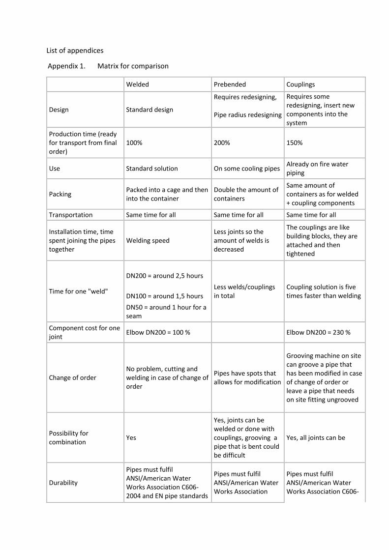
Appendix 1. Matrix for comparison
Welded Prebended Couplings
Design Standard design
Requires redesigning, Requires some redesigning, insert new components into the system
Pipe radius redesigning
Production time (ready for transport from final order)
100% 200% 150%
Use Standard solution On some cooling pipes Already on fire water piping
Packing Packed into a cage and then into the container
Double the amount of containers
Same amount of containers as for welded + coupling components
Transportation Same time for all Same time for all Same time for all
Installation time, time spent joining the pipes together
Welding speed Less joints so the amount of welds is decreased
The couplings are like building blocks, they are attached and then tightened
Time for one "weld"
DN200 = around 2,5 hours
Less welds/couplings in total
Coupling solution is five times faster than welding DN100 = around 1,5 hours
DN50 = around 1 hour for a seam
Component cost for one joint
Elbow DN200 = 100 % Elbow DN200 = 230 %
Change of order No problem, cutting and welding in case of change of order
Pipes have spots that allows for modification
Grooving machine on site can groove a pipe that has been modified in case of change of order or leave a pipe that needs on site fitting ungrooved
Possibility for combination
Yes
Yes, joints can be welded or done with couplings, grooving a pipe that is bent could be difficult
Yes, all joints can be
Durability
Pipes must fulfil ANSI/American Water Works Association C606-2004 and EN pipe standards
Pipes must fulfil ANSI/American Water Works Association
Pipes must fulfil ANSI/American Water Works Association C606-
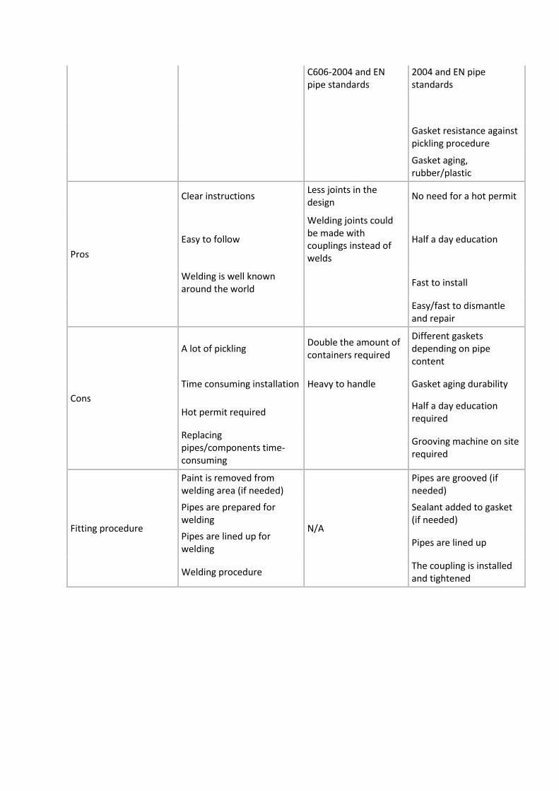
C606-2004 and EN pipe standards
2004 and EN pipe standards
Gasket resistance against pickling procedure
Gasket aging, rubber/plastic
Pros
Clear instructions Less joints in the design
No need for a hot permit
Easy to follow
Welding joints could be made with couplings instead of welds
Half a day education
Welding is well known around the world
Fast to install
Easy/fast to dismantle and repair
Cons
A lot of pickling Double the amount of containers required
Different gaskets depending on pipe content
Time consuming installation Heavy to handle Gasket aging durability
Hot permit required Half a day education required
Replacing pipes/components time-consuming
Grooving machine on site required
Fitting procedure
Paint is removed from welding area (if needed)
N/A
Pipes are grooved (if needed)
Pipes are prepared for welding
Sealant added to gasket (if needed)
Pipes are lined up for welding
Pipes are lined up
Welding procedure The coupling is installed and tightened