Cost Analysis Methodology of Spent Fuel Storage · algeria indonesia poland argentina iran,...
68
Direct disposal r T 1 Transportation 1 AFR storage Economics methodology I y Reprocessing TECHNICAL REPORTS SERIES No 361 Cost Analysis Methodology of Spent Fuel Storage ( ^ J INTERNATIONAL ATOMIC ENERGY AGENCY, VIENNA, 1994
Transcript of Cost Analysis Methodology of Spent Fuel Storage · algeria indonesia poland argentina iran,...

Direct disposal
r T 1
Transportation
1 AFR
storage
Economics methodology
I y
Reprocessing
TECHNICAL REPORTS SERIES No 361
Cost Analysis Methodology of Spent Fuel Storage
( ^ J INTERNATIONAL ATOMIC ENERGY AGENCY, VIENNA, 1994

COST ANALYSIS METHODOLOGY OF SPENT FUEL STORAGE

The following States are Members of the International Atomic Energy Agency: AFGHANISTAN ICELAND PERU ALBANIA INDIA PHILIPPINES ALGERIA INDONESIA POLAND ARGENTINA IRAN, PORTUGAL ARMENIA ISLAMIC REPUBLIC OF QATAR AUSTRALIA IRAQ ROMANIA AUSTRIA IRELAND RUSSIAN FEDERATION BANGLADESH ISRAEL SAUDI ARABIA BELARUS ITALY SENEGAL BELGIUM JAMAICA SIERRA LEONE BOLIVIA JAPAN SINGAPORE BRAZIL JORDAN SLOVAKIA BULGARIA KAZAKHSTAN SLOVENIA CAMBODIA KENYA SOUTH AFRICA CAMEROON KOREA, REPUBLIC OF SPAIN CANADA KUWAIT SRI LANKA CHILE LEBANON SUDAN CHINA LIBERIA SWEDEN COLOMBIA LIBYAN ARAB JAMAHIRIYA SWITZERLAND COSTA RICA LIECHTENSTEIN SYRIAN ARAB REPUBLIC COTE D'IVOIRE LITHUANIA THAILAND CROATIA LUXEMBOURG THE FORMER YUGOSLAV CUBA MADAGASCAR REPUBLIC OF MACEDON CYPRUS MALAYSIA TUNISIA CZECH REPUBLIC MALI TURKEY DENMARK MARSHALL ISLANDS UGANDA DOMINICAN REPUBLIC MAURITIUS UKRAINE ECUADOR MEXICO UNITED ARAB EMIRATES EGYPT MONACO UNITED KINGDOM OF EL SALVADOR MONGOLIA GREAT BRITAIN AND ESTONIA MOROCCO NORTHERN IRELAND ETHIOPIA MYANMAR UNITED REPUBLIC FINLAND NAMIBIA OF TANZANIA FRANCE NETHERLANDS UNITED STATES OF AMER GABON NEW ZEALAND URUGUAY GERMANY NICARAGUA UZBEKISTAN GHANA NIGER VENEZUELA GREECE NIGERIA VIET NAM GUATEMALA NORWAY YUGOSLAVIA HAITI PAKISTAN ZAIRE HOLY SEE PANAMA ZAMBIA HUNGARY PARAGUAY ZIMBABWE
The Agency's Statute was approved on 23 October 1956 by the Conference on the Statute of the IAEA held at United Nations Headquarters, New York; it entered into force on 29 July 1957. The Head-quarters of the Agency are situated in Vienna. Its principal objective is "to accelerate and enlarge the contribution of atomic energy to peace, health and prosperity throughout the world".
© IAEA, 1994 Permission to reproduce or translate the information contained in this publication may be
obtained by writing to the International Atomic Energy Agency, Wagramerstrasse 5, P.O. Box 100, A-1400 Vienna, Austria.
Printed by the IAEA in Austria August 1994
STI/DOC/OlO/361

TECHNICAL REPORTS SERIES No. 361
COST ANALYSIS METHODOLOGY OF SPENT FUEL STORAGE
INTERNATIONAL ATOMIC ENERGY AGENCY VIENNA, 1994

VIC Library Cataloguing in Publication Data
Cost analysis methodology of spent fuel storage. — Vienna : International Atomic Energy Agency, 1994.
p. ; 24 cm. — (Technical reports series, ISSN 0074-1914 ; 361) STI/DOC/OlO/361 ISBN 92-0-100594-6 Includes bibliographical references.
1. Spent reactor fuels — Storage — Cost effectiveness. I. International Atomic Energy Agency, n . Series: Technical reports series (International Atomic Energy Agency) ; 361.
VICL 94-00095

FOREWORD
An important aspect of the nuclear power programme is the nuclear fuel cycle, which is divided into two parts: the front end for the fuel supply to nuclear reactors, and the back end for all issues related to the spent fuel arising from these reactors after its use in producing electricity.
The back end of the nuclear fuel cycle includes all activities involving the spent fuel produced in the reactor cores. These operations can be conducted in three differ-ent ways, which define the fuel cycle:
(1) A closed cycle, with the reprocessing of the spent fuel, and the recovery and recycling of the remaining uranium and plutonium produced
(2) An open cycle, with the final disposal of the spent fuel occurring without any fuel recovery after preparation of the fuel for its final disposal
(3) Storage of the spent fuel so that it can be retrieved at a later time (perhaps tens of years), an option which defers choice of option (1) or option (2).
The concept of storage of spent fuel occurs in options (1) and (3). In the former, the fuel is stored for several years to permit the decay of radioactivity to more manageable levels; in the latter, storage takes place until a final decision is made about which fuel cycle is to be employed.
It is estimated that the capacity for reprocessing in the region formerly known as the World Outside the Centrally Planned Economies Area (WOCA) will be about 6500 t heavy metal (HM) in the year 2000, compared with a spent fuel generation of some 13 000 t HM/a. In addition, by the year 2000 about 70 000 t HM/a of cumulative spent fuel arisings will have been generated.
The report deals with the cost analysis of interim spent fuel storage; however, it is not intended either to give a detailed cost analysis or to compare the costs of the different options. This report provides a methodology for calculating the costs of different options for interim storage of the spent fuel produced in the reactor cores.
Different technical features and storage options (dry and wet, away from reac-tor and at reactor) are considered and the factors affecting all options defined. The major cost categories are analysed. Then the net present value of each option is cal-culated and the levelized cost determined. Finally, a sensitivity analysis is conducted taking into account the uncertainty in the different cost estimates.
Examples of current storage practices in some countries are included in the Appendices, with descriptions of the most relevant technical and economic aspects.
The report was prepared at three Advisory Group Meetings: in Vienna, at the Oskarshamn CLAB facility (Sweden) and at the Gorleben facility (Germany); a Consultants Meeting was held in Vienna for final revision of the text. The Agency wishes to express its appreciation to all those participants who attended the meetings and contributed valuable papers, notes, comments, etc.
The IAEA officers responsible for the project were J.L. Rojas and J.S. Finucane of the Division of Nuclear Fuel Cycle and Waste Management.

EDITORIAL NOTE
Although great care has been taken to maintain the accuracy of information contained in this publication, neither the IAEA nor its Member States assume any responsibility for consequences which may arise from its use.
The use of particular designations of countries or territories does not imply any judge-ment by the publisher, the IAEA, as to the legal status of such countries or territories, of their authorities and institutions or of the delimitation of their boundaries.
The mention of names of specific companies or products (whether or not indicated as registered) does not imply any intention to infringe proprietary rights, nor should it be construed as an endorsement or recommendation on the part of the IAEA.

CONTENTS
1. INTRODUCTION 1
2. SPENT FUEL MANAGEMENT 2
3. TECHNICAL FEATURES OF SPENT FUEL STORAGE 6
3.1. Wet storage 6 3.2. Dry storage 8
3.2.1. Metal cask 8 3.2.2. Concrete cask or silo 10 3.2.3. Vault H 3.2.4. Dry well 12
4. STORAGE OPTIONS AND COST CONSIDERATIONS 12
4.1. Identification of boundaries 12 4.2. Factors affecting all options 12 4.3. Storage options 13
4.3.1. Option 1: AR storage enhancement 13 4.3.2. Option 2: AR storage extension or
stand alone AR storage 14 4.3.3. Option 3: AFR storage 15
5. COST CONSIDERATIONS 16
5.1. Introduction 16 5.2. Identification of major cost categories 16
5.2.1. Development costs 16 5.2.2. Capital costs 17 5.2.3. Operational costs 17 5.2.4. Refurbishment costs 17 5.2.5. Decommissioning costs 20 5.2.6. Transport costs 20
5.3. Factors influencing costs 21 5.3.1. Design development 21 5.3.2. Industrial experience 21 5.3.3. Production management 21
5.4. Cost profile 22 5.5. Money value 22 5.6. Cost uncertainty 22

6. METHOD OF COST ANALYSIS 22
6.1. Expenditure analysis 22 6.2. Expenditure profile and discounting procedure
to determine the NPV 27
7. COST ANALYSIS 30
7.1. Use of the NPV 30 7.2. Levelized unit cost 31 7.3. Sensitivity and uncertainty analyses 32 7.4. Discount rate 33
8. FINANCING THE OPTIONS 34
8.1. Methods of financing the storage facility 34 8.2. Levying the charges on the consumer 36
APPENDIX I: AR STORAGE ENHANCEMENT: RERACKING WITH COMPACT STORAGE RACKS IN GERMANY 38
1.1. Introduction 38 1.2. Design 38 1.3. Experience 39 1.4. Investment costs 40 1.5. Operating costs 40
APPENDIX H: A STAND ALONE AR STORAGE FACILITY: THE TVO-KPA POOL STORAGE FACILITY AT OLKILUOTO IN FINLAND 41
n . l . Introduction 41 n .2. Design 41 n.3. Investment costs 41 n.4. Operating costs 42
APPENDIX EI: AN AFR STORAGE FACILITY: THE CLAB POOL STORAGE FACILITY AT OSKARSHAMN IN SWEDEN 43
m . l . Introduction 43 m .2 . Design 43 m .3 . Operation 43 m.4. Investment costs 45 ffl.5. Operating costs 46

APPENDIX TV: AN AFR STORAGE FACILITY: POOL STORAGE FACILITIES AT THE COGEMA REPROCESSING PLANT AT LA HAGUE IN FRANCE 47
IV. 1. Introduction 47 IV.2. Design 48 IV.3. Investment costs 49 IV.4. Operating costs 49
APPENDIX V: AN AFR STORAGE FACILITY: THE DRY CASK STORAGE FACILITY AT GORLEBEN IN GERMANY 50
V. l . Introduction 50 V.2. Design 51 V.3. Operation 51 V.4. Investment costs 51 V.5. Operating costs 52
BIBLIOGRAPHY 53
CONTRIBUTORS TO DRAFTING AND REVIEW 55

1. INTRODUCTION
There are currently two strategies to consider in the management of spent nuclear fuel: reprocessing (closed fuel cycle) and direct disposal (open fuel cycle). Reprocessing, which allows the uranium and plutonium contained in the spent fuel to be recovered for reuse, usually involves storage of the spent fuel for a period of time, typically 5-10 years, before reprocessing, followed by storage of the high level radioactive waste for several decades before disposal. The direct disposal strategy, in which the entire fuel assembly is viewed as waste, may involve storage of spent fuel for several decades before its disposal. Storage of spent fuel is an essential stage in each strategy. Some nations have not yet decided which strategy to follow; they have adopted a position of 'wait and see'. It is essential that these nations identify a spent fuel storage concept which permits the later selection and implementation of the selected spent fuel management strategy. The storage facility design may be affected by the spent fuel management strategy selected.
A spent fuel storage facility can be described by a combination of the following characteristics: heat transfer medium (i.e. wet or dry); location (i.e. at or away from the reactor); and size (i.e. the number of power stations that the facility can support). Clearly, several combinations of these characteristics exist to provide a number of options for the storage of spent fuel.
The choice of a particular storage option for a specific application will have to include consideration of the economic factors. Given the various types of facility that are available and the very different storage time-scales that could be involved, it is important to have a proper cost analysis methodology in order to compare competing storage options.
All too often comparisons of the relative costs of different spent fuel storage options are improperly presented because appropriate methodology has not been used. This erroneous analysis is sometimes compounded by attempts to compare assessments of the different spent fuel management strategies selected by different nations, using ground rules that are specifically applicable to these nations but are not necessarily applicable on a universal basis.
This report has been written for professionals involved in the development and implementation of policy decisions as well as for staff who may be technically aware of but not well experienced in the details of spent fuel storage matters. In addition, the report should act as a guide for experienced nuclear engineers.
The arrangement of the report is as follows:
Section 1 provides an introduction and overall perspective, of which this section is part. Section 2 describes the spent fuel management strategies generally being followed by most nations maintaining commercial nuclear power programmes, and identifies
1

the basic spent fuel storage options used throughout the remainder of this report to establish an appropriate methodology for cost analysis. Section 3 outlines the various spent fuel storage options chosen for development of the assessment methodology. Section 4 identifies the essential information required for each spent fuel storage option, and provides the basis for establishing the factors which enable the cost of any given storage option to be determined. Section 5 describes the important cost components relating to the factors described in Section 4. Section 6 sets out the treatment of costs involving the use of yearly cost profiles to permit discounted cost analyses. Section 7 shows how to undertake a cost analysis in terms of discounted cash flow and levelized unit costs, and includes discussion on the choice of discount rate, sensi-tivities and uncertainties. Section 8 discusses various methods of financing the storage option, and provides some country specific examples.
This report also contains five Appendices, which describe various spent fuel storage facilities currently in use or being planned for future implementation. Infor-mation on design features, construction time-scales, operational experience and costs is included in each description.
Appendix I deals with the method of increasing the spent fuel storage capacity by reracking the storage pool using compact storage racks in Germany. Appendix II describes the stand alone at reactor (AR) storage facility located at Olkiluoto, Finland. Appendix III provides a description of the away from reactor (AFR) interim spent fuel storage facility (CLAB) located near the Oskarshamn nuclear power station, Sweden. Appendix IV describes the AFR spent fuel storage facilities associated with the reprocessing plant at La Hague, France. Appendix K provides a description of the AFR spent fuel storage facility at Gorleben, Germany.
2. SPENT FUEL MANAGEMENT
Typically, fuel is discharged from a nuclear power reactor after it achieves its design burnup. The discharge normally occurs on an annual basis. In a modern light water reactor (LWR), the fuel remains in the reactor core for about 3-4 years. About 25-30 t U of spent fuel are discharged annually from a 1000 MW(e) pressurized
2

(Open fuel cycle)
I Direct disposal
Low/ Spent fuel intermediate disposal
level waste
disposal
1 1 1
AR storage
1 1 1 1
Transportation
1 1 1 l _ .
AFR storage
1 1 l _ . 1
' Spent fuel storage options considered for describing
• economics methodology
(Closed fuel cycle)
Reprocessing
Low/ intermediate
level waste
disposal
High level waste
disposal
U/Pu to reactor
energy utilization
FIG. 1. Stages of spent fuel management.
water reactor (PWR) after electricity sufficient to satisfy the needs of approximately 200 000 people has been generated. In a coal fired power station, 3.5 million tonnes of coal would have to be burned to produce the same amount of electricity.
Immediately after discharge from a reactor, spent fuel is extremely radio-active. It emits significant quantities of radiation and heat, and continues to do so for a long period of time. This spent fuel must be• managed safely until it is reprocessed or treated before final disposal. The- various stages of spent fuel management are shown diagrammatically in Fig. 1.
From this figure it can be seen that there are two spent fuel management strate-gies: reprocessing (closed fuel cycle) and direct disposal (open fuel cycle). In the reprocessing strategy, the spent fuel is chemically treated to separate the unused U (around 95 %) and Pu (around 1 % of the amount of U) from the small amount of. high level radioactive waste (up to 4% fission fragments) contained in the spent fuel. The recovered U and Pu are reusable, whereas the radioactive waste is not. In the direct disposal strategy, the entire spent fuel assembly is treated as a radioactive waste product which must be ultimately prepared for disposal. In both strategies, low and
3

Time after Decay heat (kW) 2 - irradiation AGR BWR PWR
18 GW-d/ 22 GW-d/ 33 GW-d/
io-1 (years) t U t U t U
io-1 io-1
0.25 11.2 17.8 27.5 1 4.2 6.3 10.2
5 _ 2 2.2 3.2 5.3 5 0.8 1.1 1.8
10 0.6 0.7 1.1 20 0.4 0.5 0.8
2 - 50 0.25 0.3 0.5
PWR 33 GW-d/t U
BWR 22 GW-d/t U AGR 18 GW-d/t U
10"1 10° 2 5 101
Cooling time (years) 102
F / G . 2. Thermal (decay heat) output of spent fuel with time.
intermediate level radioactive wastes are produced and must be properly conditioned for disposal. Each management strategy requires that spent fuel be stored for some period of time to permit the levels of radiation and heat being generated in the fuel to diminish, easing subsequent spent fuel handling operations. The heat emitted at various times of storage for several fuel types is illustrated in Fig. 2. From this figure it can be seen that, after discharge, a large reduction in the heat generated occurs over a relatively short period of storage time. Initial storage invariably takes place at the nuclear power station, thereby easing the task associated with the subse-quent spent fuel transport operations. Because of its good heat transfer and radiation shielding properties and because of its transparency, water is used (almost without exception) as the initial storage medium at the nuclear power station.
4

In the early years of nuclear energy production, power stations were designed and constructed with a limited spent fuel storage capacity. At that time it was antici-pated that supplies of U would be limited and that after a short initial cooling period (up to a few years) the spent fuel would be transported to a reprocessing facility so that the unused fuel could be recovered and reused. With the increasing discoveries of U and the delay in introducing large scale commercial reprocessing facilities, some nations have decided either to adopt a direct disposal strategy or to defer their decision on the final treatment of their spent fuel.
By the turn of this century around 240 000 t of spent fuel will have been dis-charged from the world's commercial nuclear power stations, with only about 20% having been reprocessed. The remainder will be located in some form of spent fuel storage. Thus, spent fuel storage over extended periods of time is now playing an increasingly important role in spent fuel management.
To avoid a shortfall in the spent fuel storage capability at a nuclear power sta-tion, the following storage options are considered:
Option 1: AR storage enhancement, to increase the storage capacity within the exist-ing AR spent fuel pool. Option 2: AR storage extension or standalone AR storage, to construct a new storage facility interconnected to the original pool or standing alone on the same site as the nuclear power station. Option 3: AFR storage, to use a storage facility that is located away from the nuclear power station site.
These three options are outlined in Fig. 3.
FIG. 3. Three options for the storage of spent fuel (arrowed lines are possible transport operations).
5

Section 3 provides a description of the technical features of the storage options defined above, dealing with both wet and dry storage concepts, and Section 4 sets out the major factors that affect the cost of each option.
3. TECHNICAL FEATURES OF SPENT FUEL STORAGE
Section 2 noted that spent fuel storage facilities must be designed to accommo-date the heat and radiation emitted by the spent fuel. In the reactor pool, water is used both for heat transfer and shielding. In spent fuel cooled for a longer period, sufficient heat transfer can be provided by a gaseous atmosphere, thus permitting dry storage. In this case, the storage facility must include adequate shielding to protect personnel. Further, the facility must be constructed of materials compatible with the spent fuel under normal operating and accident conditions. This section briefly describes the design concepts currently being used or considered for spent fuel storage. Further details may be obtained by referring to IAEA Technical Reports Series Nos 218, 240 and 290 (see Bibliography). Specific examples of a number of different storage concepts are presented in detail in Appendices I-V.
3.1. WET STORAGE
Because of its excellent heat removal characteristics, along with its good radia-tion shielding properties and optical transparency, water has historically been chosen as the preferred medium for spent fuel storage. More than 30 years of operational experience have been accumulated all over the world for spent fuel storage in water.
Most LWR fuel storage pools are of similar design, rectangular in horizontal cross-section and 12-13 m deep. Fuel assemblies are placed in storage racks or baskets located at the bottom of the pool. The racks hold the assemblies in a vertical position and maintain the prescribed spacing between assemblies to prevent critical-ity. The assemblies are normally inserted or removed vertically from above the racks, using mechanical handling systems. LWR fuel assemblies (typically about 4.5 m in length) remain submerged during all fuel handling operations. The mini-mum shielding requirement is about 3 m of water. Generally, LWR rack depths are about 4.5 m, therefore 12-13 m of water is ample for fuel insertion into stationary racks. Radiation levels at the pool surface from all stored fuel are very low because a total of about 8 m of water shielding is usually available (equivalent to about 3.5 m of concrete).
Pools are equipped with cooling systems and normally operate at 40°C or less. Cleanup systems are provided to maintain good water chemistry; these may be integral with the cooling system. An air cleaning system is also required. All these
6

É&3 F u e l
preparation machine
FIG. 4. Cross-section showing the relationship of the BWR core and the spent fuel pool.
Fuel encasement
pool
FIG. 5. Cross-section showing the relationship of the PWR core and the spent fuel pool.
7
systems give rise to radioactive waste (ion exchanger resins, particulate and air filters) which must be conditioned before disposal. The pool walls and floor are con-structed of reinforced concrete of a thickness sufficient to meet the radiation shield-ing and structural requirements. Pools are usually lined with welded stainless steel plates that are approximately 5 mm thick. The thickness of the concrete walls varies from 0.3 to 2 m, and the floor thickness from 1 to 2 m. Many pools have leak detec-tion and collection systems.
Normally, boiling water reactor (BWR) fuel storage pools are located inside the reactor containment. In early BWR designs, the pools were elevated approxi-mately 15-30 m above ground level, as shown diagrammatically in Fig. 4. More recent BWRs have ground level storage pools because the elevated position has higher seismic load design requirements, and therefore higher costs.
Basically, PWR systems use a storage pool located in an auxiliary structure outside the containment building, as shown diagrammatically in Fig. 5. In some cases, small storage pools inside the reactor containment provide further storage. The refuelling operations require opening the reactor vessel and raising the water level to that in the pool. Fuel is removed from the reactor core and placed on a strong metal frame, which reverts to a horizontal position for movement through the fuel transfer tunnel into the transfer canal. In this canal, the fuel is raised to a vertical position, picked up by the spent fuel pool handling machine, moved to the storage pool and placed in fixed storage racks. Often during these operations the fuel is moved to an inspection area for visual observation by either an underwater periscope or television equipment. Equipment must be provided to service the underwater storage facilities and to enable the spent fuel to be removed.
3.2. DRY STORAGE
Dry storage is complementary to wet storage, since dry storage requires initial cooling of the spent fuel in a pool prior to storage. Dry storage technology has been developed for the following design concepts: metal cask; concrete cask or silo; vault; and dry well. The dry well concept has been investigated but is currently not being developed actively. The concepts are distinguishable by their major characteristics, namely, the predominant heat transfer method; shielding; mobility; location with respect to the geological surface; degree of independence of the individual storage cells; and storage structure.
3.2.1. Metal cask
This is a massive metal container that may be used to transport as well as store spent fuel. It contains one or more storage cavities with a controlled environment. Storage cavities can be designed to hold several spent fuel assemblies. Shielding and
8

FIG. 6. Conceptual design for a typical metal storage cask.
Removable lifting lugs
Lifting embeds
Fuel storage cask lid
Inner shield plug
Axial neutron shielding
Concrete shielding
Decontaminatable coating
Fuel basket
Cask cavity liner
Fuel assemblies
Drain
FIG. 7. Conceptual design for an unventilated concrete storage cask.

radioactive particulate confinement is provided primarily by cask structural material such as steel or cast iron. Heat removal is by conduction through the structural material to the atmosphere. The conceptual design for this type of storage is shown in Fig. 6.
3.2.2. Concrete cask or silo
This is a large monolithic structure, usually of reinforced concrete. The con-crete provides shielding, but containment is usually provided by an inner steel vessel. The inner vessel is sealed after fuel loading. A silo is not portable. Figures 7 and 8 show diagrams of unventilated and ventilated casks, respectively. These are similar in design, with the exception that the ventilated type is equipped with inlet and outlet airflow ducts. This permits greater dissipation of heat per unit area, hence a greater heat load can be accommodated in a cask of this type.
10

1. Cooling air inlet duct 11. Transfer cask trolley 2. Fuel handling machine 12. Health physics control station 3. Fuel handling machine crane 13. Ventilation stack outlet 4. Shielded storage tubes 14. Fuel handling machine depression 5. Transfer cask system cubicle 6. Transfer cask preparation area 15. Charge face structure 7. Transfer cask load/unload port 16. Charge face slabs 8. TCRB electrical plant room 17. Subcharge face volume 9. Filter room 18. Collimators
10. Stairwell 19. MVDS entrance (personnel) 20. Nitrogen bottle store (nitrogen system)
FIG. 9. Cutaway view of the modular vault dry storage (MVDS) system.
3.2.3. Vault
A vault can be located above or below ground level; it is a reinforced concrete structure containing an array of storage cavities. Each storage cavity can be designed to contain one or more spent fuel assemblies. Shielding is provided by the surround-ing structure. Primary heat removal is by forced or natural convection of air over the exterior of the cavities. This heat is transferred to the atmosphere directly or indirectly, depending on the system design. Some systems also use a secondary cool-ing circuit. A typical design of the modular vault dry storage (MVDS) system developed in the United Kingdom is shown in Fig. 9.
11

3.2.4. Dry well
A dry well is a stationary, below ground, lined, individual cavity. Each storage cavity may be designed to contain several spent fuel assemblies. The actual number of fuel assemblies is determined by the fuel and storage media. Shielding is provided by the surrounding earth and closure shield plug. Primary heat removal is by conduc-tion into the earth. Each of the dry storage concepts has storage cavities. These cavi-ties contain a storage medium called a cover gas. The storage medium can be air, nitrogen, carbon dioxide or any of the inert gases — helium, argon or neon. Cover gas selection is based on the storage temperature and the various interactions between the gas and the cladding and fuel pellets.
4. STORAGE OPTIONS AND COST CONSIDERATIONS
The purpose of this section is to describe, for each option identified in Sec-tion 2, the various factors that have to be taken into consideration in establishing the cost of spent fuel storage. The discussion identifies the major cost components that comprise each option.
4.1. IDENTIFICATION OF BOUNDARIES
For the purpose of analysis it is assumed that each nuclear power station has been provided with a certain amount of spent fuel storage capacity (in the form of a pool) as part of the initial station installation. Only enhancement of this storage capacity and its associated costs are considered in this report. The process for disposal or treatment of the spent fuel subsequent to storage is not examined. Accordingly, the components to be considered start with measures that can increase the storage capacity beyond that of the existing pool and include all subsequent requirements for storage through to the delivery of the spent fuel to the final disposal or treatment facility.
4.2. FACTORS AFFECTING ALL OPTIONS
The characteristics of the spent fuel are of major importance and affect all the options, particularly the design of the storage facility and its subsequent operation. The characteristics that must be considered are: fuel type(s) (geometry, weight and enrichment); burnup (minimum to maximum range); cooling time (decay heat); radionuclide inventory; and the physical state of the clad (clad failure and external contamination).
12

The fuel type(s) to be stored determines the design of the fuel handling and storage equipment, including the dimensions of the facility, e.g. the depth of the fuel storage pool. Fuel burnup and cooling time determine the decay heat to be removed and the safety measures, including criticality control, that must be considered.
The basic parameters required to define the spent fuel storage scenario are: the quantity of fuel to be stored; delivery schedule; storage period; and retrieval schedule.
The size of the facility required to accommodate a given quantity of fuel could be influenced by consideration of 'economy of scale' factors, which may be different for each of the storage technologies involved.
The behaviour of each fuel type depends on the storage environment. The physical state of the clad at the start of the storage period and the maximum storage period must also be considered in selecting the design of the facility.
The delivery and retrieval schedule and, hence, the loading and unloading rates will affect the method of transporting the spent fuel to and from the facility. This will determine the type and design of the receiving and handling equipment needed.
4.3. STORAGE OPTIONS
4.3.1. Option 1: AR storage enhancement
Option 1 requires major modifications to the internals of the pool. The problems likely to be encountered include: where to place the spent fuel already present in the pool during these modifications; the possible additional dose commitment to plant personnel; and possible secondary radwaste production. AR enhancement can be achieved by reracking, double tiering or rod consolidation.
(1) Reracking enables the storage capacity of an existing pool to be increased by reducing the separation of the fuel assemblies by use of racks constructed of materials which have an enhanced neutron absorption capability. In this option, the original storage racks, usually made of stainless steel or aluminium, are replaced by racks made of borated steel, boron in aluminium or cadmium in stainless steel. Only minor modifications in the spent fuel transfer system are necessary, and the overall handling sequence of spent fuel in the storage pool is not changed. The main factors affecting the cost of reracking are: modification to the existing spent fuel pool design (weight loading, decay heat removal, etc.); design and purchase of the new racks (neutron absorption and structural requirements); removal, decontamination and disposal of the old racks; and installation of the new racks.
(2) Double tiering requires the addition of another level of storage racks above the racks already in place. Existing AR storage pools were originally designed for only
13
one level of storage racks. The pool depth must be sufficient to ensure acceptably low radiation doses to the operators. The structural design may limit the feasibility of adding another level of racks without major modification of the storage pool inter-nals. Major modification of the spent fuel transfer system may be required and the operational flexibility of spent fuel movements may be impaired. The main factors affecting the cost of double tiering are: modification to the existing spent fuel pool design (weight loading, decay heat removal, etc.); design and purchase of the new racks; and installation of the new racks.
(3) Rod consolidation involves the withdrawal of the fuel rods from the assembly grids and subsequent placement of these rods in a container, which is then sealed and returned to one of the original rack spaces. To date, a consolidation factor1
approaching 2 has been achieved. If consolidation is undertaken within the existing pool, it must be remembered that the equipment used will occupy some space that could otherwise be used for fuel storage. Also, the separated assembly grids and end fittings would again potentially occupy fuel storage space, unless they are removed from the pool. Use of an independent hot cell consolidation facility would overcome both of these potential difficulties but would incur its own specific costs. The main factors affecting the cost of rod consolidation are: modification to the existing spent fuel pool design (weight loading, decay heat removal, etc); possible rack redesign; container design and purchase; rod consolidation equipment and operation (in-pool or independent facility); management of the assembly grids and fittings; and implementation of IAEA safeguards requirements.
4.3.2. Option 2: AR storage extension or stand alone AR storage
Option 2 requires the construction of an AR storage facility, which can be accomplished through the utilization of either of the following alternatives:
(1) By building a new pool interconnected to the existing pool. In this case, there is the potential to use existing fuel handling and auxiliary support systems.
(2) By building an independent (stand alone) storage facility at the reactor site. From a technical point of view, this facility can be operated independently of the reactor, although an additional on-site spent fuel transfer system is required. In principle, such a store could use either wet or dry storage technology.
The main factors affecting the cost of extending the existing pool are: the design, construction and operation of the extension; the possible additional fuel
1 The consolidation factor is the ratio of the amount of spent fuel that can be fitted into a given space after consolidation to the amount of fuel that occupied the same space prior to consolidation.
14

handling and auxiliary support service equipment; and the impact on the operation of the existing pool. The main factors affecting the cost of building an independent, stand alone storage facility on the reactor site are: the design and construction of the storage facility (including land and infrastructure requirements); the design and implementation of the fuel transfer system between the reactor pool and the storage facility; and the impact on the operation of the storage facility beyond the end of reactor lifetime.
4.3.3. Option 3: AFR storage
Option 3 requires a completely independent spent fuel storage facility that is located away from the reactor site and is able to serve one or more nuclear power stations. This type of store permits phased development, perhaps with the use of a modular design, to meet storage demand. Such a facility could employ either wet or dry storage technology.
Use of AFR storage requires off-site transport of the spent fuel; this must com-ply with national/international standards. Licensed transport cask designs are avail-able that use either wet or dry technology. The design of the fuel and transport cask handling facilities must take into account the possibility of the fuel residing in both wet and dry environments.
AFR storage facilities may be built at a national level. For example, a country may build its own AFR storage facility, or a country may utilize a facility that is located outside the national boundary, as when such a facility is co-located with a reprocessing plant to which there is a contractual reprocessing commitment.
There are two main ways in which a utility may obtain the use of an AFR storage facility. The first would involve the utility buying a storage service under contract from an independent supplier. The second would involve the utility in an active role in developing and establishing such a facility. In the latter case, the main factors affecting the cost of providing an AFR storage facility are: the establishment of a new nuclear licensed site (including environmental assessment, local consultants and possible public inquiry procedures); the design and construction of the storage facilities (including land and infrastructure requirements); the design and implemen-tation of the fuel transport system between the AR and AFR facilities; and the possible impact on operational requirements if the AFR store is located on or close to an already licensed nuclear site, whereby some support services may be shared.
Where the active role in establishing an AFR facility involves a utility acting in collaboration with other parties, e.g. other utilities and/or developers, considera-tion will have to be given to the way in which costs will be allocated to the various participants. This is particularly important where a joint facility has been designed to accommodate different fuel types, possibly including fuel in consolidated form.
15

5. COST CONSIDERATIONS
5.1. INTRODUCTION
Section 4 identified the major factors that affect the costs of the storage options. This section focuses on identification of the appropriate cost categories and how these categories should be brought together in a consistent way to enable a proper comparison of storage options.
A number of factors will influence the overall cost of any storage option. These factors include the ability to manage the planning and development of a particular option, along with the capability to implement it subsequently. Lack of industrial experience can result in unrealistically low cost estimates in the planning stage and give rise to significant cost overruns during the development and construc-tion/implementation stages.
A proper cost analysis of the various options requires identification of the detailed costs. These costs may be grouped into different categories and described in such a way that they can be applied to all the options.
Consideration of cost uncertainties is essential in making proper comparisons of the competing storage options. Uncertainties need to be defined for each cost esti-mate when the detailed cost data are being assembled. Details of all these cost con-siderations are given in the following subsections.
5.2. IDENTIFICATION OF MAJOR COST CATEGORIES
This subsection identifies the major cost categories for each storage option so that a comprehensive checklist can be drawn up. These categories are: development costs; capital costs; operational costs; refurbishment costs (including any additional developments); and decommissioning costs. These are outlined in Table I to provide a comprehensive checklist for each of the storage options. This list can be used to ensure that all the cost categories have been considered and are included in the evalu-ation. It should be noted that, while not all the specific cost categories defined in Table I are equally weighted for each option, they must all be taken into considera-tion (apart from the exceptions noted).
5.2.1. Development costs
Development costs can be defined as those expenses incurred from the initial studies up to the decision to construct the spent fuel storage facility. Specific types of development costs include: initial feasibility studies to identify the storage options available; the conceptual design of the spent fuel storage facilities; and all other costs
16
required to analyse or evaluate each storage option before commencing construction (including site characterization). Except for the following, all spent fuel storage options require substantial development activities: double tiering; reracking; and metal casks. Double tiering and reracking are well developed and therefore entail relatively low development costs. Metal storage casks are now available commer-cially, therefore development costs may not be involved.
5.2.2. Capital costs
Capital costs can be defined as those expenses incurred from the time the owner decides to construct the facility up to the time the facility commences opera-tion. Specific components of capital costs include: land acquisition; site preparation; design and engineering; infrastructure and site improvements; building and construc-tion (including bulk materials and direct labour); process equipment (including mechanical, electrical and instrumentation equipment); services (water, steam, com-pressed air, electricity, etc.); commissioning; and all other expenses incurred during construction, including quality assurance, insurance, indirect labour costs, public relations and other overheads. Although capital costs are associated with each spent fuel storage option, the magnitude of these costs varies over a wide range, depending on the option selected. Relatively low capital costs are associated with double tiering, reracking and rod consolidation, whereas significant capital costs can be expected with the other options.
5.2.3. Operational costs
Operational costs can be defined as all those expenses associated with the utili-zation of the facility. These costs are usually specified on an annual basis and include: direct labour; indirect labour (including administration and overheads); materials and goods; on-site transport (transfer); maintenance; services (water, elec-tricity, fuel supplies, etc.); support requirements (environmental monitoring; physical protection, safeguards etc.); waste conditioning and disposal; insurance; taxes and duty costs; and quality assurance. Operational costs may be relatively low for those options that use facilities based on passive design principles such as the metal cask, vault, concrete cask or silo.
5.2.4. Refurbishment costs
Refurbishment costs are usually associated with major replacement of the existing plant when it becomes obsolete, when its licence has expired, or because of demands to upgrade the plant to satisfy the licensing authority. Refurbishment costs include those expenses which result from operational experience or are associated with the research and development normally initiated by the operator to
17

TABLE I. STORAGE OPTIONS AND RELATED COST CATEGORIES
Storage option Development Capital Operational Refurbishment Decommissioning Other
AR: Option 1
Double tiering NA A A A A
Reracking NA A A A A (a)
In-pool consolidation A A A A A
AR: Option 2
AR extension pool A A A NA A
Stand alone
Pool NA A A A NA A
Metal casks NA A A NA A
Concrete casks A A NA NA A
Horizontal concrete system A A NA NA A
Vault A A A A A
Transfer and handling A A A A A A
Site NA A A NA A

Storage option Development Capital Operational Refurbishment Decommissioning Other
Transportation A A
AFR wet storage
Pool A A
In-pool consolidation A A
AFR dry storage
Metal casks NA A
Concrete casks NA A
Horizontal concrete system A A
Dry wells A A
Vault A A
Site A A
(a) Treatment and disposal of the old racks.
NA = cost category not applicable to the storage option. A = cost category applicable to the storage option.
AFR: Option 3
A A A
A NA A
A A A
NA NA A
NA NA A
A A A
NA NA A
A A A
A NA A

improve the existing system. Refurbishment costs are more likely to be encountered in long term storage scenarios. Examples of refurbishment or continuing develop-ment costs include: replacement or improvement of plant instrumentation; replace-ment or improvement of the physical protection system; experimental studies on rod consolidation; improved capabilities for the handling of damaged fuel assemblies; and development of non-destructive testing techniques for evaluation of the spent fuel behaviour.
5.2.5. Decommissioning costs
This category of costs includes all those activities associated with final shut-down, decontamination and site restoration subsequent to spent fuel removal from the site. The costs may vary significantly, depending on the option initially selected for spent fuel storage. Specific decommissioning costs include those expenses associated with: facility shutdown; surveillance and maintenance (when applicable); decontamination of equipment and facilities; waste conditioning, transport and dis-posal; system dismantling; removal of buildings and structures; and site restoration. Each of these costs may have components of: labour cost; supervision and over-heads; administration; environmental monitoring; and personnel radiation monitor-ing and protection. Although decommissioning costs are associated with all the identified spent fuel storage options, these costs can be expected to be quite different, depending on the selected option. In general, it is expected that wet storage facilities will have higher decommissioning costs than dry storage facilities.
5.2.6. Transport costs
Although transport costs are not shown as a separate category in Table I, they are a feature common to all storage options. Figure 3 indicates the extent of possible transport operations, shown as arrowed lines. Transportation costs include the capi-tal costs of the transport casks, transport vehicles, associated operating costs and any necessary refurbishment. The magnitude of these costs will depend on the storage option considered, together with the transport mode. Transportation may be considered as an operational cost if the actual transport is carried out by an indepen-dent company under contract. Otherwise, the costs associated with transport will have to take into account the capital, operational and refurbishment costs shown in subsections 5.2.2, 5.2.3 and 5.2.4, respectively. In addition, it may be necessary to include costs for the construction or improvement of the transportation infrastruc-ture, including road improvements, extension of the existing transport network, har-bour facility improvements, etc.
20

5.3. FACTORS INFLUENCING COSTS
There are many variables that influence cost estimates, and experience has shown that the projected and actual costs associated with the development and production of material goods usually differ. There are common factors that influence most cost estimates. The most important factors are discussed in the following subsections.
5.3.1. Design development
Preliminary cost evaluations are normally performed to identify the merit of a concept before undertaking its development. These cost evaluations can be refined at each development stage and when modifications become necessary to the original design specification. All systems are developed to meet an original design specifica-tion. Modification of the specification could invalidate the original projected cost. Modification of one design variable such as the fuel type (with the associated burnup characteristics) could affect several design components, resulting in a cost change. Therefore, extreme care should be exercised in selecting and utilizing the parameters that define the specification. Preliminary design cost estimates are typically lower than subsequent, more detailed, cost evaluations, since they usually do not account for material details, exact labour requirements, institutional/regulatory costs and unanticipated problems associated with development, fabrication, production and operation.
5.3.2. Industrial experience
The accuracy of cost estimates also depends on actual experience in industrial production. Organizations that have maintained up to date expertise in manufacturing techniques can produce components with a higher degree of quality, usually at a lower cost, and always nearer the cost estimate than organizations that have not done so. Organizations with little or no individual production experience may be unable to secure a licence to manufacture nuclear components and, hence, their cost esti-mates may be subject to great uncertainty.
5.3.3. Production management
The form of management used to direct and control labour in design and production activities will have an effect on costs. Application of excessive manage-ment demands through the design, fabrication and production phases can result in cost escalations due to administrative, quality assurance and other support activities. Lack of appropriate management techniques could result in post-production costs to correct those inadequacies not identified during the design/production phase.
21

5.4. COST PROFILE
To be able to assess and compare the overall cost of storage options properly, it is necessary to provide, for each option, the underlying component cost on a yearly basis. At this stage, the costs used must exclude financing charges; these are dealt with in Sections 6, 7 and 8. The overall expenditure profile for each option is then determined by aggregation of all the component costs.
5.5. MONEY VALUE
It is essential that all costs in the expenditure profile are expressed in a consis-tent money value. For this purpose, the money value for each cost component must be identified clearly during cost data acquisition. All costs should then be converted to a common money base related to a convenient point in time. This will ensure that the costs are expressed consistently so as not to prejudge possible future inflationary trends. This latter point is considered in more detail in Section 7.
5.6. COST UNCERTAINTY
Invariably, any cost estimate has an uncertainty associated with it. For a com-plex system such as a storage facility, there are many factors which contribute to the overall cost uncertainty. It is desirable to estimate the cost uncertainty for each com-ponent and to take these into account in the overall assessment. For spent fuel storage, there will also be uncertainty in the design specification of the facility and the scenario being considered. The way in which uncertainties are taken into account is discussed in Section 7.
6. METHOD OF COST ANALYSIS
6.1. EXPENDITURE ANALYSIS
The costs (for each category described in Section 5) for each of the compo-nents for the various spent fuel storage options, together with the uncertainties relat-ing to these costs, are estimated. They should then be aggregated and analysed to permit a choice between the storage options. The widely approved and accepted way of doing this is based on discounted cost analysis. The principles underlying this approach are set out below.
22

The basis of this approach is that a time series of future costs may be represented by a sum of money which, if invested now, would, together with the interest earned, meet the costs as they arise, with no surplus remaining. The sum to be invested may be determined by discounting (at the assumed interest rate) the costs from their actual time of occurrence to an appropriate reference point in time. This procedure results in a single representative cost that is known as the net present value (NPV). Thus, if a number of options exist, each with its own sequence of costs, the most economic option is the one having the lowest NPV. In practice, this choice would not be made without due regard to the significance of cost uncertainties and non-economic factors, e.g. political, regulatory, technical and other factors. The NPV of a project is defined as the sum of the discounted cost stream associated with that project, that is
„ q NPV = ^
(1 + d ) '
where Q is the cost or expenditure in the i-th year; d is the appropriate discount rate; i is the year index; and the summation is over all years where there is a cost or expenditure on the project.
This formulation permits the analyst to account for the fact that a cost at a future time has a smaller 'present value' due to interest.
To see more clearly how this methodology operates, a specific example is provided. The first task is to define very clearly and explicitly exactly what an option entails. The next task is to construct the series of annual costs for each option,
Facility A
Facility B
J I I I I I I I I I I I I I I I I I I I 1 2 3 4 5 6 7 8 9 10 11 12 13 1 4 1 5 16 1 7 1 8 19 20
Years
Construction Operation Decommissioning
FIG. 10. Facility activities over time.
23

TABLE II. ASSUMED FACILITY PARAMETERS
Parameter
Facility
Parameter A B
Construction
Delay before start of construction (year) 0 4
Time to build (years) 3 4
Annual cost (currency) 10 15
Operation
Delay before start of operation (year) 0 0
Life (years) 5 5
Annual cost (currency) 1 2
Decommissioning
Delay until start of decommissioning (years) 4 4
Time to decommission (years) 3 3
Annual cost (currency) 2 3
excluding financing charges. To do this, it is necessary to build up the overall expen-diture profile for each storage option by combining the yearly component costs for each storage option. In the current context, Section 5 sets out the cost categories of each storage option. An overall expenditure profile is required for each storage option. One then discounts the expenditure profile to a convenient and consistent point in time. This could, for example, be the time at which the first cost is incurred for any option. In comparing the costs of storage options it is essential that the refer-ence point in time is the same in each case. The rate to be used depends on a number of considerations, particularly those of financing. Selection of an appropriate dis-count rate is discussed in Section 7.
It is convenient, but not essential, to express cost profiles in constant money terms that specifically exclude allowance for inflation. In this case, the discount rate should also be inflation free. Conversely, if the cost profiles allow for inflation, then the discount rate used should reflect that assumption. It is essential that the assump-tions are applied in a consistent way when analysing the costs of competing storage options.
A numerical example of the compilation of an expenditure profile and the dis-counting procedure to determine the NPV is set out in subsection 6.2.
24
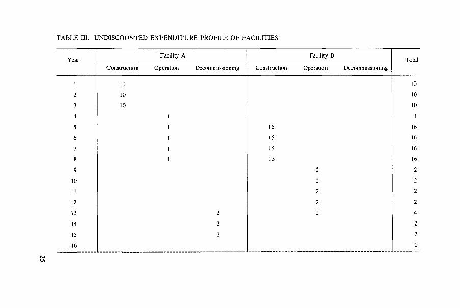
TABLE III. UNDISCOUNTED EXPENDITURE PROFILE OF FACILITIES
Year Facility A Facility B
Total Year Construction Operation Decommissioning Construction Operation Decommissioning
Total
1 10 10
2 10 10
3 10 10
4 1 1
5 1 15 16
6 1 15 16
7 1 15 16
8 1 15 16
9 2 2
10 2 2
11 2 2
12 2 2
13 2 2 4
14 2 2
15 2 2
16 0
N) LTi
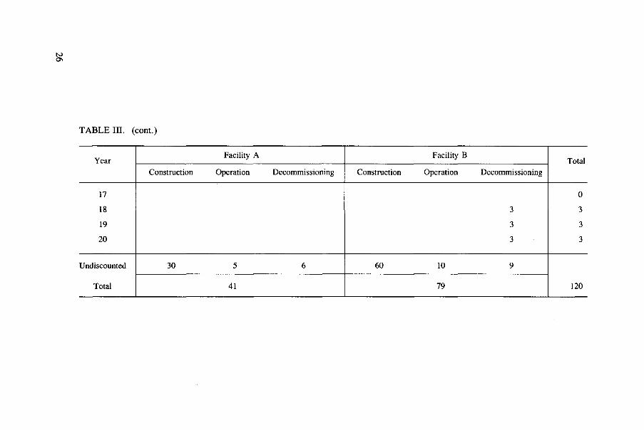
TABLE III. (cont.)
Year Facility A Facility B
Total Year Construction Operation Decommissioning Construction Operation Decommissioning
Total
17 0
18 3 3
19 3 3
20 3 3
Undiscounted
Total
30 5 6 60 10 9
120
Undiscounted
Total 41 79 120

6.2. EXPENDITURE PROFILE AND DISCOUNTING PROCEDURE TO DETERMINE THE NPV
The details of the option to be considered are defined in Fig. 10 and Table II. This example option includes two facilities, A and B. The benefits are not shown in this NPV example, but these would normally also be provided quantitatively to ensure that the option was capable of providing the required results (and, of course, all 'comparable' options must provide the 'required' results).
The next stage is the construction of an expenditure profile by determining the costs and when these will be incurred for each component. This example option again includes two facilities, A and B. For simplicity, only a limited number of items has been included for each facility: the delay before start of construction, the annual expenditures during construction, the delay before start of operation, the annual operating costs and, finally, the decommissioning timetable and costs. The costs are defined in a constant (first year's) money value. To ensure the correct timing of the costs of the various facilities for this option, the construction of a diagram, similar to that shown in Fig. 10, is valuable.
The expenditure profile for this simplified example is shown in Table III, first for each facility and then as an aggregate sum for both facilities (see Fig. 11). This overall spending profile represents the undiscounted total of yearly expenditures, in constant money terms, for the complete option. In a similar way, expenditure profiles may be constructed for other options.
I Facility A
I Facility B
10 11 12 13 14 15 16 17 18 19 20
Years
FIG. 11. Undiscounted expenditure profile of facilities.
27

TABLE IV. DISCOUNTED EXPENDITURE PROFILE OF FACILITIES (AT 5% PER ANNUM)
Year Facility A Facility B
Total Year Construction Operation Decommissioning Construction Operation Decommissioning
Total
1 10.00 10.00
2 9.52 9.52
3 9.07 9.07
4 0.86 0.86
5 0.82 12.34 13.16
6 0.78 11.75 12.54
7 0.75 11.19 11.94
8 0.71 10.66 11.37
9 1.35 1.35
10 1.29 1.29
11 1.23 1.23
12 1.17 1.17
13 1.11 1.11 2.23
14 1.06 1.06
15 1.01 1.01
16 0
17 0
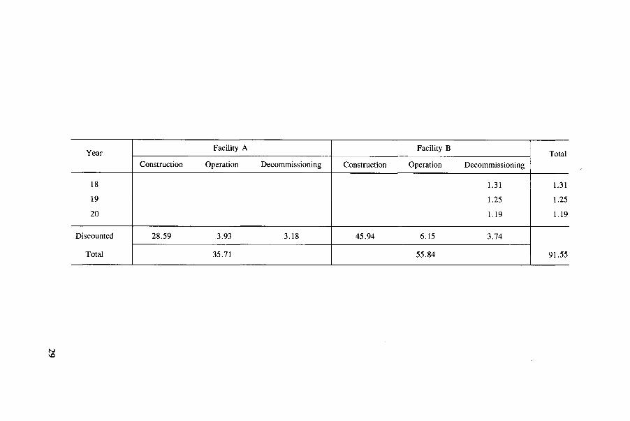
Year Facility A Facility B
Total Year Construction Operation Decommissioning Construction Operation Decommissioning
Total
18 1.31 1.31
19 1.25 1.25
20 1.19 1.19
Discounted
Total
28.59 3.93 3.18 45.94 6.15 3.74
91.55
Discounted
Total 35.71 55.84 91.55

14 I l Facility A
Facility B
1 2 3 4 5 6 7 8 9 10 11 12 13 14 15 16 17 18 19 20 Years
FIG. 12. Discounted expenditure profile of facilities (at 5% per annum).
The expenditure profile thus constructed represents the cost of the option in the year's money chosen with no allowance for inflation, financing, etc. The NPV of this option is derived by discounting the expenditure profile back to the selected point in time — in this case, the start of construction of Facility A. The discounted version of Table III is shown in Table IV, which is represented graphically in Fig. 12. For this example, all expenditures are assumed to occur at the end of each year; a 5% per annum discount rate has been used for demonstration purposes.
In the example shown, the option comprising Facilities A and B has an undis-counted cost of 120 currency units. When discounted at 5% per annum this becomes 91.55 currency units, which is the NPV for this option. This NPV could then be com-pared with the NPV of another option, which also would provide equivalent benefits.
Each storage option comprises different kinds of facility. The costs associated with these facilities occur on a particular schedule, which will vary from option to option (see example given in subsection 6.2). The NPV is the appropriate index of overall costs to compare competing options. Section 6 described the requirements
7. COST ANALYSIS
7.1. USE OF THE NPV
30

for determining the NPV for an option, particularly the need to compile expenditure profiles.
For any storage option, expenditures would consist of a series of costs if the required facilities are provided internally, or of a series of payments if the services are acquired from an external supplier. A mixture of costs and prices is possible. For example, reracking an existing storage pool would involve a series of costs, while later use of an AFR storage facility operated by an independent service company would entail a series of payments. The NPV can be derived for each of the competing options. The cost of each option will be represented by its NPV; the lower the NPV, the higher its ranking order.
7.2. LEVELIZED UNIT COST
Up to this point only the NPV has been discussed and suggested as a measure for economic evaluation of an individual option. Another economic measure, which may provide the analyst with an insight into the actual unit costs, can also be used. This alternative measure is the levelized unit cost (LUC) and is defined as the ratio of the sum of the discounted cost stream (NPV) to the sum of the discounted benefit stream net present benefit (NPB). The discounted benefit stream (NPB) is formed in exactly the same way as the discounted cost stream, that is
NPB = = E (1 + d)1
where Q; is the benefit to be derived in the i-th year (waste stored, electricity gener-ated, etc.); d is the discount rate; i is the year index; and the summation is over all years where the project provides a benefit.
This formulation permits one to express the fact that 'benefit' in the future is not as useful as 'benefit' now. In this case
L U C = ^ NPB
Levelized unit costs may be determined over various periods of time, for example, the operating lifetime or the economic lifetime of the storage facilities. It should be noted that if two options are comparable, they will have the same benefit stream (i.e. providing those benefits that are required). They will also, therefore, have the same NPB. Therefore, the ranking of options according to the NPV will be identical to the ranking of options by the LUC. However, since the LUC is formed as the ratio of costs to benefits (both discounted), the LUC will provide an estimate of the unit benefit cost (US $/MW-h; US $/t U stored, etc).
31

If costs are recovered from revenue, then the NPV of costs should equal the NPV of revenue. Thus
The NPV of costs = the NPV of revenue
y C' = y fy
i - , 0 + d ) ' j = i + d> j
where Q is the cost in year i; Rj is the revenue in year j; d is the discount rate per annum; and the summation is over all years where there is a cost (sum over i) or over all years where there is income or revenue (sum over j).
Great caution must be exercised in deriving and using costs given in unit terms. In the context of fuel storage, for example, in order to derive values that can be properly compared it is necessary to discount the amount of fuel placed in a storage facility (the benefits) in exactly the same way as the expenditures (the costs) were discounted. Clearly, use of LUC as a measure of comparison is specific to a given scenario. It should not be used to compare different fuel storage scenarios, particu-larly when the rates of fuel arising and the period of storage differ.
7.3. SENSITIVITY AND UNCERTAINTY ANALYSES
As noted in Section 6, cost uncertainties must also be considered. It may be that the choice between the two options depends less on the ranking order of the NPV than on the associated uncertainty. For example, it might be judged that in particular circumstances it is preferable to choose an option with a low uncertainty rather than one with a lower NPV but with a higher uncertainty. How to determine levels of risk is set out below.
It is necessary to establish the sensitivity of the NPV of the option to changes in assumptions about cost parameters, particularly those parameters which by inspec-tion are likely to have a dominant effect on the NPV. This can be done simply by changing the value of a parameter, say by +10%, which will affect the cost-time profile and produce a change in the NPV. The sensitivity is then simply expressed as the ratio of the change in the NPV to the change in the parameter value (e.g. US $ change in the NPV per year extension in facility lifetime). Sensitivities may also be expressed in terms of the LUC; these represent their normalized value relative to a unit of benefit.
The parameters that might be subjected to a sensitivity analysis include: dis-count rate, to reflect uncertainties in the macroeconomic environment; currency exchange rates, which have an effect on the prices of imported materials or services; filling rate of storage facilities; lifetime of facilities; operating lifetime of facilities;
32

economic lifetime of facilities; capital, operational, refurbishment and decommis-sioning costs; and time delays in project development (arising, for example, from construction and licensing delays).
The final stage involves the expression of judgement of the analyst on the level of uncertainty that is associated with the individual parameters. This is necessarily subjective and will depend largely on experience, which may vary from country to country. The combination of component uncertainties and the respective sensitivities noted above can then be used to come to a judgement on the overall uncertainty in the costs for a particular storage option. The total uncertainty is the sum of the individual uncertainties; the individual uncertainties are the product of the cost sensi-tivity to a particular parameter times the assumed uncertainty in that parameter. An overall view of uncertainty (risk) will additionally have to encompass non-economic factors, which may include political, regulatory and other considerations.
7.4. DISCOUNT RATE
The example given in Section 6 assumed, for illustrative purposes, a discount rate of 5% per annum. This section describes how an economic assessment could be carried out without specifying the appropriate value of discount rate to use. The following paragraphs discuss the factors that can be taken into account in deciding on the appropriate discount rate to be used in real situations. These factors should reflect the financing and economic background of the option and the time-frame over which it occurs. In Section 8, the approaches adopted for financing spent fuel storage in a number of countries are outlined to provide an indication of the different prac-tices currently in use.
It must be recognized that spent fuel storage may be prolonged, possibly for 50 years or more. Over such long periods of time it is extremely difficult to predict with accuracy the prevailing economic conditions and, hence, the discount rate that would be appropriate. In economic assessments it is possible to use discount rates that vary in time. If this is done, then such variations must be applied consistently to all the competing storage options. In all cases, the discount rate should be appropriate to the macroeconomic conditions of the framework (country, region, international financial markets, etc.), including the interactions between the different regions and countries.
The source of funds to finance the option could be domestic, public (govern-ment) or private, or loans from the international money markets (including the World Bank, the International Monetary Fund and other international institutions). Interna-tional money markets often provide funds at a low interest rate and long repayment periods to developing countries. In countries where economic conditions are adverse, where there is a limited amount of domestic capital or where there is a limited amount of foreign currency available, it would be appropriate to use a higher
33

discount rate than would be used if economic circumstances were more stable and predictable.
Where costs are to be recovered via revenue, the period of recovery may be short or long. If the recovery time is long, it could cover times of adverse economic performance leading to financial risk, and the discount rate might be chosen conser-vatively (higher) to reflect this. Factors which effect the period of cost recovery include the mechanisms of recovery, which might relate to the operating lives of plants, payment schedules and electricity tariffs. In the particular case of prepay-ments, the financial risk is reduced; this could lead to use of a less conservative, and even risk free, discount rate. If the cost recovery arrangements are required to achieve an element of profit, then this may be represented by an increase in the dis-count rate, which is then reflected in an increase in the LUC.
8. FINANCING THE OPTIONS
A number of examples of the financing of storage options are given with refer-ence to actual practice in specific countries. The financing method that is chosen takes into account the payments schedule for the storage facility or service and also the way in which the utility obtains the money from the electricity consumer.
8.1. METHODS OF FINANCING THE STORAGE FACILITY
In some cases, the storage requirements may be relatively small and involve only one utility. Such facilities may be financed in a similar way to the construction and operation of the power station, with the costs being recovered through the price of electricity. Extension of existing storage capacity attached to a power station is likely to be financed in this way. For example, reracking of station pools has been undertaken on this basis in Germany and Japan. In the United States of America, the utilities are responsible for the financing of all spent fuel storage requirements until such time as the US Department of Energy (DOE) takes title to the spent fuel. In Finland, the TYO-KPA-STORE facility is being financed in this manner during the operating period of the TVO I and II power stations.
Where the storage requirements are larger and reflect the needs of many utili-ties, a number of different schemes have been developed. Some have significant government involvement, some do not. Most provide for a series of advanced pay-ments and some mechanism for changing payments to account for actual costs differ-ing from costs projected far into the future. Specific examples to illustrate this process are given below.
34

One way of funding these larger scale facilities is for an independent service organization to seek a contractual commitment, including advance payment to cover the construction, operational and decommissioning costs, which may also provide a profit.
Multiple stage payments in reprocessing contracts are an example of this pay-ment method. Payments are made before the service is provided. This is typical of the contracts between British Nuclear Fuels pic (BNFL)/Compagnie générale des matières nucléaires (Cogéma) and their overseas customers. Such contracts involve the storage of spent fuel prior to reprocessing. Under these contracts, customers pro-vide money to the service suppliers in three stages of advance payments and a final payment. Advance payments include an initial payment of a pro rata share of the investment costs (including storage facilities) and payment of a part of the operating costs upon delivery of the spent fuel to the reprocessors. The final payment, which covers the remaining costs and adjustments, is made when the fuel is actually reprocessed.
Another way of funding these facilities is for the government to control the method and level of funding and to approve the payments that are made in accor-dance with agreed submissions by the service organization.
Examples of this type of payment are as follows. In the USA, the Nuclear Waste Policy Act authorizes programme expenditures for civilian radioactive waste management under three accounts. Two of these, the Interim Storage Fund and the Nuclear Waste Fund (NWF), are special funds established in the US Treasury. (There has been no request for Federal interim storage services, hence there are no funds in this account.) The DOE Office of Civilian Radioactive Waste Management (OCRWM) is responsible for the management of the NWF. This fund was estab-lished to ensure that the government recovers from the owners and generators of radioactive waste the full cost of the disposal services it provides. Nuclear utilities pay a fee to the NWF to cover the full cost for the disposal of commercial spent fuel. Funds are provided from the NWF to the DOE to support all OCRWM programme activities associated with the repository, monitored retrievable storage, transporta-tion, systems integration and programme management. In addition, utilities with a nuclear power station must store their own spent fuel until such time as the DOE takes title to it.
In Sweden, assessment of future costs is made by the Swedish Nuclear Fuel and Waste Management Company (SKB) on behalf of the utilities. This assessment has to be agreed to by the government agency, National Board for Spent Nuclear Fuel (SKN), before it is used for payment purposes.
A similar arrangement is used in Spain, where annually revised cost estimates are made by Empresa Nacional de Residuos Radiactivos, S.A. (ENRESA) and presented in the General Radioactive Waste Plan. These estimates are subsequently agreed to by the government.
35

In Finland, utilities provide the funds to cover the cost of continued operation and eventual decommissioning of the TVO-KPA-STORE facility after the TVO I and II power stations have been shut down. These future storage costs have to be secured by the utility in a method agreed to by the government.
In Germany, the Brennelementlager Gorleben (BLG) organization was founded to build and operate the interim storage facility at Gorleben. BLG is a sub-sidiary of the Deutsche Gesellschaft für Wiederaufarbeitung von Kernbrennstoffen (DWK), which is jointly owned by the 11 German electric utilities that have nuclear power stations. Annual operating costs, including depreciation, are borne by the customers, pro rata to their contractual shares. In return, they are entitled to storage capacity in the Gorleben interim storage facility according to their contractual extent. Storage casks are ordered when they are needed by each nuclear power station, the respective utility paying for its own casks.
Another example is the Japanese situation, where nuclear power utilities have decided to construct a large storage facility as part of the proposed new reprocessing plant at Rokkasho-Mura, which is to be constructed and operated by a joint venture company, the Japan Nuclear Fuel Service Company.
8.2. LEVYING THE CHARGES ON THE CONSUMER
Utilities seek to recover the cost of storage as part of the electricity price. They should recover such costs not as part of the electricity price during the period of storage but as part of the price charged when the fuel concerned was producing elec-tricity. In this way, intertemporal fairness among electricity consumers is achieved.
In Germany, all Entsorgung (German term for all back end fuel cycle activi-ties, including spent fuel storage) costs are recovered by a fee included in the price of nuclear generated electricity. The cost estimate for the Entsorgung is evaluated on the basis of contracts and other estimates, including risk coverage for the Entsorgung as well as for the nuclear wastes arising from the operation of the power plant and for the decommissioning of the plant itself.
In France, a provision is made in Electricité de France (EDF) accounts to cover the cost of reprocessing and waste disposal of all the spent fuel. The amount charged to customers is determined by estimating the price of reprocessing and the cost of waste disposal.
Japanese utilities have a similar financial arrangement to cover the back end of the fuel cycle. The utilities are authorized to keep reserve funds that are just suffi-cient to cover the estimated costs of spent fuel management based on the reprocessing of all the spent fuel (including that part of the fuel still in the reactor core at a speci-fied time in each fiscal year). The cost estimates are updated annually and adjust-ments are made for inflation. The reserve fund may be invested in the utilities'
36

business to earn a profit or it may otherwise be invested to earn interest. However, the profits or interest earned are not credited to the reserve fund.
The UK utilities follow a similar practice to that described for Germany and Japan. However, when making a provision in the accounts for expenditure that will occur well into the future, beyond the shutdown of the power station, a 2% per annum (real term) interest accrual is assumed in determining the annual level of pro-vision to be made.
The US utilities are responsible for providing sufficient resources to ensure the safe storage of spent fuel until such time as the DOE takes title to it. In the USA, nuclear utilities have so far been assessed a fee of 1 mill/kW • h on electricity sold to provide OCRWM funding for the recovery of the full cost for all those activities associated with spent fuel disposal.2 The money obtained through this fee is invested in US Treasury securities and earns interest (assumed 7% actual interest rate on a positive yearly balance). The OCRWM is responsible for providing a compre-hensive analysis of the total cost of the radioactive waste management system over its complete life-cycle each year as part of the required annual evaluation of the ade-quacy of the disposal fee to cover these costs.
A similar approach has been adopted in Sweden. Here, SKN makes a recom-mendation to the government concerning the fee to be levied in the coming years after examining SKB's annual cost assessment for total spent fuel management. The utilities levy this fee on the consumers and the resulting money is invested in an interest earning account in the Royal Bank of Sweden. The cost of spent fuel storage is identified as one of a number of separate items within the overall spent fuel management costs.
Spain also uses this type of approach for the funding of the back end of the nuclear fuel cycle. However, in this case the levy is calculated by spreading the money to be recovered from the consumer across all electricity sales, including non-nuclear generation. The rate of the levy is authorized by the government when approving the report submitted by ENRESA. This takes into account all the antici-pated spent fuel management costs according to estimates in the General Radioactive Waste Plan. Thus, the revenues resulting from the levy, when added to the accumulating, interest earning fund, are just sufficient to cover the projected future expenditure for all back end fuel cycle operations, including spent fuel storage.
2 mill = US $10"3 = 0.1 C.
37

Appendix III
AR STORAGE ENHANCEMENT: RERACKING WITH COMPACT STORAGE RACKS IN GERMANY
1.1. INTRODUCTION
In the past, most storage pools of a nuclear power station were designed to store a limited number of discharged fuel batches, together with the full core reserve. It was assumed that after a decay period of some months the fuel assemblies would be despatched in transport casks to a reprocessing plant or another storage facility. Experience has shown that operationally and economically it is useful and prudent to make maximum use of the reactor pool for extended storage of fuel assemblies. More intensive use of the reactor pool can be achieved by reracking with compact storage racks.
1.2. DESIGN
Installation of compact storage racks (Fig. 13) increases the capacity of existing pools by a factor of 2 to 2.5 by introducing neutron absorbers, thus enabling a reduction in the spacing between the stored fuel assemblies. By more effective use of the pool space, the pool can provide the capacity to store fuel assemblies from 10 additional years of operation (in some cases even for the entire design lifetime of 30 years).
Subcriticality is calculated using proven computer codes according to existing engineering regulatory guides such as the KTA 3602, ANS-57.2 or IAEA Safety Guide No. 50-SG-D10 (see Bibliography).3 In PWRs, the presence of boric acid in the pool water (and taking into account a minimum amount of burnup) allows an even greater reduction in the distance between assemblies. This does not apply to full core reserves, where minimum burnup may not have occurred.
Owing to the rapid decay of short lived radioactive isotopes after reactor shut-down, the decay heat and radioactivity in the fuel pool tend to be dominated by the newly discharged fuel assemblies. The decay heat generated after discharge of the entire reactor core of a 1300 MW plant, for example, is about 16 MW, whereas the decay heat of the ten preceding discharge batches totals only about 4.5 MW, of which 3.5 MW are generated by the most recent batch alone. The case is similar for the radioactivity. These considerations are of particular interest in the context of
3 KTA = Kerntechnischer Ausschuss, Cologne, Germany; ANS = American Nuclear Society, Hinsdale, IL, USA.
38

FIG. 13. Installation of compact storage racks at the Unterwieser nuclear power plant, Germany.
increasing the storage capacity of existing pools by reracking. Both the decay heat and radioactivity inventory increase only slightly (extra capacity is taken up by long discharged fuel), with the result that capacity increases can be implemented without changes to the cooling system.
The load on the pool floor and interference between the storage rack module and the pool liner have to be analysed in detail individually. The structure of the storage rack module itself is analysed with respect to static and dynamic behaviour.
1.3. EXPERIENCE
Increased storage capacities permit greater storage duration, which in turn requires that the fuel cladding remains leaktight and that the fuel assemblies are capa-ble of being handled throughout the storage period. The possible defect mechanisms that might give rise to loss of integrity of the cladding are known from reactor opera-tion and are prevented by suitable fuel assembly design and coolant chemistry con-trol. Operating experience, even under reactor service conditions (high temperatures
39

and pressures), has been shown to be very good. Experiments performed in laborato-ries and in post-irradiation examinations on fuel assemblies which have been in storage for long periods have confirmed that protracted storage for fuel assemblies poses negligible risk. Research programmes performed outside Germany have reached the same conclusion.
An important part of the compact storage racks is the neutron absorbing material. There are four main types on the market: (1) boron, silicon bount; (2) boron, dispersed within aluminium; (3) cadmium; and (4) borated stainless steel.
For types (1) and (2), periodic in-service inspection or a periodic surveillance programme is usually employed to demonstrate that adequate neutron absorber is being maintained. In Germany (and in some other countries such as Finland, Hungary, Spain and the USA), borated stainless steel is used as the neutron absorber without any necessity for in-service inspection.
1.4. INVESTMENT COSTS
The investment costs depend on: the type of fuel assembly; maximum 235U enrichment of the fuel assembly; design of the rack module and interference with the pool liner; and type of neutron absorber.
The costs for removal of the old racks are about US $0.3/kg U and for installa-tion of the new racks about US $0.5-0.7/kg U. The costs of high grade decontami-nation and subsequent conventional disposal of the racks are about Deutsche Mark (DM) 10/kg steel. Additional costs arise for the conditioning and disposal of the secondary waste. Costs for reuse of the material of the old racks (e.g. for castings used in the nuclear field) are about DM 7/kg steel. Additional costs arise for disposal of the slag. A third alternative for cutting and compaction of the racks costs about DM 6/kg steel. By compaction, approximately 50% of the theoretical density can be reached. Disposal costs are about DM 5300/m3.
1.5. OPERATING COSTS
These are not influenced by reracking.
40

Appendix III
A STAND ALONE AR STORAGE FACILITY: THE TVO-KPA POOL STORAGE FACILITY
AT OLKILUOTO IN FINLAND
11.1. INTRODUCTION
At the Olkiluoto nuclear power station the storage space in reactor pools was sufficient until about 1990. To ensure adequate space for spent fuel beyond that date, Teollisuuden Voima Oy (TVO) has built at Olkiluoto a pool type interim storage facility called the TVO-KPA-STORE. This facility started operation in 1987. It was built as a stand alone AR storage facility on the power station site. The storage facility is unmanned, apart from periods when fuel transfer from the reactor pools is taking place. The vital process systems of the facility are duplicated. The TVO-KPA-STORE will be a completely independent storage facility after the decommissioning of TVO I.
11.2. DESIGN
The storage capacity as constructed will be enough for all the spent fuel arising from 30 years of operation of TVO I and II, about 1270-1400 t U. The design of the store allows for enlargement of this capacity. The planned service life is 60 years. Fuel assemblies will cool off for at least 1 year in the reactor pools before being transferred to the TVO-KPA-STORE, where they will be kept for up to 40 years. Additionally, one design requirement is that it must be possible to handle and store practically all existing BWR and PWR fuels in racks or baskets.
The TVO-KPA-STORE utilizes some process systems of TVO I, including demineralization and fire extinguishing water supplies, pressurized air, hot and cold water systems and liquid and solid waste treatment systems. Spent fuel is transferred from the power plant to the TVO-KPA-STORE in a CASTOR-TVO cask. This modular cast iron cask can contain up to 41 BWR assemblies cooled, for. 3=5 -years, i.e. about 7.3 t U. The loaded cask weighs about 93 t without impact limiters. No cooling fins are used. Water coolant inside the loaded cask remains under 100°C, with a total permitted heat load of 22 kW.
11.3. INVESTMENT COSTS
The investment costs given in Table V are for Phase I of the TVO-KPA-STORE, having one storage pool with spent fuel racks and two empty pools (FIM = Finnish markka).
41

TABLE V. BREAKDOWN OF INVESTMENT COSTS, OLKILUOTO, FINLAND (FIM X 106 (1987 VALUE))
Design and administration 37
Construction 65
Fuel handling and storage 37
Process and mechanical systems 31
Instrumentation system 6
Electrical equipment 9
Total 185
The net present value of the total investment costs when using a 5 % per annum average construction cost index is FIM 198 x 106. It has been estimated that the total costs over the lifetime of the store will be roughly FIM 352 X 106.
II.4. OPERATING COSTS
The TVO-KPA-STORE is operated by TVOI personnel and is unmanned dur-ing normal operation, when spent fuel transfers are not being performed. The most important alarm systems are connected to the TVO I control room. Operational per-sonnel supervise the stores regularly. Essential services and maintenance operations are performed by nuclear power plant maintenance organizations. Thus, the operat-ing costs of the TVO-KPA-STORE cannot easily be separated out, since a large number of systems are integrated into those of TVO I (Table VI).
After the decommissioning of TVO I, the independent TVO-KPA-STORE will be operated by a staff of 14 persons, including security personnel. It is assumed that no spent fuel transfers willj)ccur. The operating costs have been estimated at less than FIM 6.6 x 10⁶/a. Personnel costs represent half of the operating costs.
TABLE VI. FACILITY CHARACTERISTICS/ OPERATING COSTS, OLKILUOTO, FINLAND (FIM X 106 (1987 VALUE))
Loading rate (t U/a)
Pool capacity (t U)
Total operating costs (FIM/a)
40-50
1200
2.6
42

Appendix III
AN AFR STORAGE FACILITY: THE CLAB POOL STORAGE FACILITY AT OSKARSHAMN IN SWEDEN
III.l. INTRODUCTION
The CLAB facility (Fig. 14) is located on the Simpevarp Peninsula near the Oskarshamn nuclear power station, which has three reactors (01, 02, and 03) and is owned by the Oskarshamnsverkets Kraftgrupp (OKG). This choice of site provides a number of advantages, for example, access to an existing harbour and use of OKG's interim storage facility for low and intermediate level wastes, central work-shops, and supply of water and electricity. OKG has also been contracted to operate CLAB and therefore part of its specialized staff can be utilized in the facility. CLAB is an example of a wet independent interim storage facility.
III.2. DESIGN
The present storage capacity is 3000 t U. In the near future, the capacity will be extended to 5000 t U by installing neutron absorbing borated fuel canisters in the existing pools. Both PWR and BWR fuels will be stored in CLAB.
The introduction of remote controlled maintenance in accordance with the design philosophy involves higher investment costs than those for the more tradi-tional pool design. On the other hand, the concept is expected to result in a safer facility, fewer shutdowns, efficient maintenance and low dose commitments. This will, in time, give a return on investment.
III.3. OPERATION
The performance of the CLAB facility has so far (1993) been satisfactory. Since start of operation, about 1200 t U, or 400 casks, have been received and unloaded. The activity release to the environment (water and air) has been less than 0.2% of the release limit valid for the site. The amount of intermediate level waste generated (mainly ion exchange resins) has been reduced to about one-third com-pared with the volumes generated during the first year of operation. The collective dose to personnel and contractors yearly has been in the range of 60-70 mman-Sv, which is a factor of 4 lower than that calculated in the final safety report.
43

FIG. 14. The Simpevarp Peninsula with the CLAB complex in the foreground and the three power units (OKG) in the background, Sweden.

TABLE VII. BREAKDOWN OF DEVELOPMENT COSTS, CLAB FACILITY, SWEDEN (%)
Project management, engineering and design 30
Civil engineering 40
Process, mechanical, electrical and control equipment 30
III.4. INVESTMENT COSTS
At the time the decision was taken to proceed with investment (March 1980), the overall investment costs were estimated to be about Swedish Krone (SK) 1300 x 106 (1980 value) for the period 1980-1985. In 1985, the final cost proved to be SK 1725 X 106. The development costs during this period can be seen in Table VII.
The 35 % increase in costs was mainly due to the fact that some basic assump-tions were changed during the design development and construction phases. The changes originated to a great extent from the experience gained from a foreign facil-ity and from new data on activity release from fuel surfaces. These factors entailed, for example, a greater ventilation capacity in the receiving hall, and the introduction of a waste treatment system that differed from the original one. Another important factor was the decision not to complete the storage section in two steps, as was origi-nally planned, but to proceed directly to a 3000 t U storage capacity.
TABLE VIII. BREAKDOWN OF OPERATING COSTS, CLAB FACILITY, SWEDEN (1989 VALUE)
SK x 106 % of total
Staff and labour 35.3 54.0
Maintenance and services 15.0 23.0
Electric power 6.0 9.0
Fuel storage countries 5.7 9.0
Assurance and authority 2.0 3.0
Miscellaneous 1.0 2.0
Total 65.0 100.0
45
III.5. OPERATING COSTS
The operational staff in the CLAB facility comprises 60 persons. As the facility is located near the Oskarshamn nuclear site, with its three power stations, a number of co-ordination advantages exist. These are access to an existing harbour and the availability of services (low and intermediate level waste management and interim storage facilities, central workshops and administration services) that are bought from OKG. Expressed in man-years, this support corresponds to some 30 to 40 persons. The operating costs are given in Table VIII.
46

Appendix III
AN AFR STORAGE FACILITY: POOL STORAGE FACILITIES
AT THE COGEMA REPROCESSING PLANT AT LA HAGUE IN FRANCE
IV. 1. INTRODUCTION
France has been reprocessing spent nuclear fuel since 1958 at the Marcoule UP1 plant.and the La Hague UP2-400 plant. In France, spent fuel is first stored for a short cooling period at the nuclear power station in a pool associated with each PWR unit. It is then transported (by rail or road) to the reprocessing plants. Two new reprocessing plants at La Hague (UP3 and UP2-800) are now operating. In these plants, spent fuel will be stored in a centralized pool storage facility before reprocessing. This storage arrangement is shown diagrammatically in Fig 15.
FIG. 15. Spent fiiel reception, unloading and storage complex at La Hague, France.
47

IV.2. DESIGN
This pool storage complex, the largest in the world, has a total capacity of 10 000 t U. For maximum flexibility in operations, the storage pools, unloading units and both the UP2-800 and UP3 reprocessing plants will be interconnected through the pools. Both PWR and BWR fuel will be stored at La Hague. About two-thirds of the fuel will be PWR and one-third BWR.
TABLE IX. BREAKDOWN OF INVESTMENT COSTS FOR THE STORAGE POOL COMPLEX, LA HAGUE, FRANCE (FF x 106 (1986 VALUE))3
Wet unloading NPH unit with a 2000 t U storage pool (NPH pool) 1350
Dry unloading TO unit with a 2400 t U storage pool (D pool) 1490
C pool with a 2400 t U capacity") E pool with a 4000 t U capacity)
880
Total 3720
a Maximum unloading rate = 1600 t U/a; total capacity of pools = 10 000 t U.
TABLE X. BREAKDOWN OF INVESTMENT COSTS, LA HAGUE, FRANCE(%)
Wet unloading Dry unloading Storage
NPH a TO" pools
Design development 16 22 24
Civil engineering 20 14 15
Piping, process equipment 47 47 45
Process, control instrumentation 7 8 12
Pre-operating 10 9 4
Total 100 100 100
a Including the 2000 t U pool associated with the NPH unit. b Including the 2400 t U pool associated with the TO unit.
48

TABLE XI. BREAKDOWN OF OPERATING COSTS, LA HAGUE, FRANCE (1986)a
FF x 106 % of total
Staff and labour 60 55.0
Maintenance and services 30 26.0
Fuel storage casks 9 8.0
Electric power ventilation 11 5.5
Insurance and authority 4 3.5
Fees and miscellaneous 1 1.0
Total 115 100.0
a Maximum unloading rate = 1600 t U/a; total capacity of pools = 4400 t U.
IV.3. INVESTMENT COSTS
The overall investment costs for the storage pool complex, including the NPH and TO unloading units and the NPH, C, D and E pools, are given in Table IX; these are broken down into component costs in Table X.
IV.4. OPERATING COSTS
The overall operating costs for the and TO unloading units and the NPH and the year 1986.
storage pool complex, including the NPH C storage pools, are given in Table XI for
49

Appendix III
AN AFR STORAGE FACILITY: THE DRY CASK STORAGE FACILITY AT GORLEBEN
IN GERMANY
V.l . INTRODUCTION
Power stations in Germany are equipped with compact racks, resulting in AR storage capacities of nine to twelve reloads with full core reserve. To meet the demand for spent fuel storage capacities in the long run, DWK decided in 1979 to make use of the dry storage of spent fuel in dual purpose transport/storage casks. The storage facility built at Gorleben in Lower Saxony is an independent facility serving all the nuclear power plants in Germany (Fig. 16).
FIG. 16. Storage for spent fuel elements in the AFR interim storage facility at Gorleben, Germany.
50

V.2. DESIGN
The storage capacity is 1500 t U held in a maximum of 420 transport/storage casks. Storage time will be up to 40 years. Both PWR and BWR fuels will be stored at the facility. The facility will also be used in the future for storing vitrified high level waste held in suitable transport/storage casks (Table XII).
TABLE XII. FACILITY CHARACTERISTICS, GORLEBEN, GERMANY
1500
9
40
Storage capacity (t U)
Cooling capacity (t U)
No. of operators
V.3. OPERATION
In September 1983, a storage licence was granted.
V.4. INVESTMENT COSTS
On the basis of existing construction experience, the characteristic cost figures shown in Table XIII are appropriate for a Gorleben type storage facility with a capacity of 1500 t U. This cost assumes that the site area is limited, so that the storage hall has sufficient wall thickness to provide additional shielding.
The costs for the casks are not included in these figures. The overall investment costs of DM 60 X 106 for a facility with a capacity of
1500 t U can~be broken down as shown in Table XIV.
TABLE Xm. BREAKDOWN OF INVESTMENT COSTS (EXCLUDING CASKS), GORLEBEN, GERMANY (DM X 106 (1988 VALUE))
30
30
Storage hall
Infrastructure, security, etc.
51

TABLE XIV. BREAKDOWN OF INVESTMENT COSTS, GORLEBEN, GERMANY (%)
Project management, design
Civil construction
Mechanical, electrical and control equipment
20
50
30
V.5. OPERATING COSTS
The storage facility requires about 40 persons for operation, including security guards, etc. The overall annual operating costs will consist almost exclusively of per-sonnel costs. Each cask costs about DM 2 X 10⁶. For cooling times of 2-3 years, such a cask can hold up to about 6 t U. Recently designed and manufactured casks for 5 year old spent fuel have a capacity of about 10 t U. Casks are now under development for spent fuel that has been cooled for longer periods. For 10 year old fuel, the capacity of the casks may even be increased to 14-16 t U. Casks are ordered by the utilities when they are needed. Cask manufacturing takes about 1 year.
52

BIBLIOGRAPHY
GUAIS, J .C. , "Economics of the back end of fuel cycle: Controversy, uncertainties and the industrial evidence", Waste Management (Proc. Conf. New York, 1987), American Society of Mechanical Engineers, New York (1987) 29-36.
INTERNATIONAL ATOMIC ENERGY AGENCY, Back End of the Nuclear Fuel Cycle: Strategies and Options (Proc. Symp. Vienna, 1987), IAEA, Vienna (1987).
INTERNATIONAL ATOMIC ENERGY AGENCY, Fuel Handling and Storage Systems in Nuclear Power Plants, Safety Series No. 50-SG-D10, IAEA, Vienna (1984).
INTERNATIONAL ATOMIC ENERGY AGENCY, Guidebook on Spent Fuel Storage, Second Edition, Technical Reports Series No. 240, IAEA, Vienna (1991).
INTERNATIONAL ATOMIC ENERGY AGENCY, Nuclear Power and Fuel Cycle: Status and Trends 1991, Part C, IAEA Yearbook, IAEA, Vienna (1991).
INTERNATIONAL ATOMIC ENERGY AGENCY, Nuclear Power, Performance and Safety (Proc. Conf. Vienna, 1987), Vol. 5, IAEA, Vienna (1988).
INTERNATIONAL ATOMIC ENERGY AGENCY, Nuclear Power, the Environment and Man, IAEA, Vienna (1982).
INTERNATIONAL ATOMIC ENERGY AGENCY, Projected Costs of Nuclear and Conven-tional Base Load Electricity Generation in Some IAEA Member States, LAEA-TECDOC-569, IAEA, Vienna (1990).
INTERNATIONAL ATOMIC ENERGY AGENCY, Review of Available Options for Low Level Radioactive Waste Disposal, IAEA-TECDOC-661, IAEA, Vienna (1992).
INTERNATIONAL ATOMIC ENERGY AGENCY, Storage of Water Reactor Spent Fuel in Water Pools: Survey of World Experience, Technical Reports Series No. 218, IAEA, Vienna (1982).
INTERNATIONAL ATOMIC ENERGY AGENCY, Survey of Experience with Dry Storage of Spent Nuclear Fuel and Update of Wet Storage Experience, Technical Reports Series No. 290, IAEA, Vienna (1988).
INTERNATIONAL MONETARY FUND, International Financial Statistics, IMF, Washing-ton, DC (Dec. 1991).
JONES, P.M.S., "The economics of the back end of the nuclear fuel cycle", Back End of the Nuclear Fuel Cycle: Strategies and Options (Proc. Symp. Vienna, 1987), IAEA, Vienna (1987) 223-235.
NUCLEAR ENERGY AGENCY OF THE OECD, The Economics of the Nuclear Fuel Cycle in OECD Member Countries, OECD, Paris (1984).
ORGANIZATION FOR ECONOMIC CO-OPERATION AND DEVELOPMENT, Decom-missioning of Nuclear Facilities — An Analysis of the Variability of Decommissioning Cost Estimates, OECD, Paris (1991).
53

ORGANIZATION FOR ECONOMIC CO-OPERATION AND DEVELOPMENT, Projected Costs of Generating Electricity from Power Stations for Commissioning in the Period 1995-2000, OECD, Paris (1990).
ORGANIZATION FOR ECONOMIC CO-OPERATION AND DEVELOPMENT, The Costs of Generating Electricity in Nuclear and Coal Fired Power Stations, OECD, Paris (1983).
ROGLANS-RIBAS, J. , SPINRAD, B.I., The back end of the nuclear fuel cycle: Technical and economic analysis, Nucl. Technol. (Mar. 1990).
SAEGUSA, T., MAKI, Y., et al., "Technical and economic assessment of storage systems for spent fuel from commercial LWRs" , Back End of the Nuclear Fuel Cycle: Strategies and Options (Proc. Symp. Vienna, 1987), IAEA, Vienna (1987) 353-360.
STOLL, W. , The economy of the nuclear fuel cycle, J. Nucl. Mater. (Jul. 1989).
SWEDISH NUCLEAR FUEL SUPPLY COMPANY, Plan 86, Costs for Management of the Radioactive Waste from Nuclear Power Production, Rep. SKB TR-86-12, SKB, Stockholm (1986).
54

CONTRIBUTORS TO DRAFTING AND REVIEW
Abreu, A.
Ay ala, L.C.
Baillif, L.
Caspar, G.
Closs, K.D.
Dodds, R.
Duchatelle, L.
Epstein, J.
Gravalos, J .M.
Groom, D.J. (Chairman)
Gustaffson, B.
Head, C.R.
Meiches, C.
Nöda, T.
Nokhamzon, J.G.
Ogawa, T.
Ortega Carmona, R.
Ospina, C.
Empresa Nacional de Residuos Radiactivos S.A.,
Spain
Comisión Nacional de Energía Atómica, Argentina
Société générale nucléaire, France
Compagnie générale des matières nucléaires,
(Cogéma), France
Kernforschungszentrum Karlsruhe, Germany
British Nuclear Fuels pic, United Kingdom
Commissariat à l'énergie atomique, France
United States Department of Energy,
United States of America
Empresa Nacional de Residuos Radiactivos S.A.,
Spain
Nuclear Electric pie, United Kingdom
Swedish Nuclear Fuel and Waste Management
Company, Sweden
United States Department of Energy,
United States of America
Empresa Nacional de Residuos Radiactivos S.A.,
Spain
Power Reactor and Nuclear Fuel Development
Corporation, France
Commissariat à l'énergie atomique, France
Science and Technology Agency, Japan
Comisión Federal de Electricidad, Mexico
Paul Scherrer Institute, Switzerland
55

Salo, J.P. Teollisuuden Voima Oy, Finland
Strahl, J .F. Roy F. Weston, Inc., United States of America
Yamaji, K. Central Research Institute of Electric Power Industry, Japan
Yano, S. Science and Technology Agency, Japan
Advisory Group Meetings
Vienna, Austria: December 1987 Oskarshamn, Sweden: August 1988
Gorleben, Germany: April 1989
Consultants Meeting
Vienna, Austria: October 1989
o o 56

HOW TO ORDER IAEA PUBLICATIONS
•ft -ft In the United States of America and Canada, the exclusive sales agent for IAEA publications, to whom all orders and inquiries should be addressed, is:
UNIPUB, 4611 -F Assembly Drive, Lanham, MD 20706-4391, USA
•ft "ft In the following countries IAEA publications may be purchased from the sources listed below, or from major local booksellers. Payment may be made in local currency or with UNESCO coupons.
ARGENTINA
AUSTRALIA BELGIUM
CHILE
CHINA
FRANCE
GERMANY
HUNGARY INDIA
ISRAEL ITALY
JAPAN NETHERLANDS
PAKISTAN POLAND
ROMANIA RUSSIAN FEDERATION
SLOVAK REPUBLIC SOUTH AFRICA
SPAIN
SWEDEN UNITED KINGDOM
YUGOSLAVIA
Comisión Nacional de Energía Atómica, Avenida del Libertador 8250, RA-1429 Buenos Aires Hunter Publications, 58A Gipps Street, Collingwood, Victoria 3066 Service Courrier UNESCO, 202, Avenue du Roi, B-1060 Brussels Comisión Chilena de Energía Nuclear, Venta de Publicaciones, Amunategui 95, Casilla 188-D, Santiago IAEA Publications in Chinese: China Nuclear Energy Industry Corporation, Translation Section, P.O. Box 2103, Beijing IAEA Publications other than in Chinese: China National Publications Import & Export Corporation, Deutsche Abteilung, P.O. Box 88, Beijing Office International de Documentation et Librairie, 48, rue Gay-Lussac, F-75240 Paris Cedex 05 UNO-Verlag, Vertriebs- und Verlags GmbH, Dag Hammarskjöld-Haus, Poppelsdorfer Allee 55, D-53115 Bonn Librotrade Ltd., Book Import, P.O. Box 126, H-1656 Budapest Oxford Book and Stationery Co., Scindia House, New Delhi-110 001 YOZMOT Literature Ltd., P.O. Box 56055, IL-61560 Tel Aviv Librería Scientifica Dott. Lucio di Biasio "AEIOU", Via Coronelli 6, 1-20146 Milan Maruzen Company, Ltd, P.O. Box 5050, 100-31 Tokyo International Martinus Nij'hoff International, P.O. Box 269, NL-2501 AX The Hague Swets and Zeitlinger b.v., P.O. Box 830, NL-2610 SZ Lisse Mirza Book Agency, 65, Shahrah Quaid-e-Azam, P.O. Box 729, Lahore 3 Ars Polona, Foreign Trade Enterprise, Krakowskie Przedmieácie 7, PL-00-068 Warsaw llexim, P.O. Box 136-137, Bucharest Mezhdunarodnaya Kniga, Sovinkniga-EA, Dimitrova 39, SU-113 095 Moscow Alfa Publishers, Hurbanovo námestie 3, SQ-815 89 Bratislava Van Schaik Bookstore (Pty) Ltd, P.O. Box 724, Pretoria 0001 Diaz de Santos, Lagasca 95, E-28006 Madrid Diaz de Santos, Balmes 417, E-08022 Barcelona Fritzes Information Centre, S-106 47 Stockholm HMSO, Publications Centre, Agency Section, 51 Nine Elms Lane, London SW8 5DR Jugoslovenska Knjiga, Terazije 27, P.O. Box 36, YU-11001 Belgrade
•ft -ft Orders (except for customers in Canada and the USA) and requests for information may also be addressed directly to:
f' ^ j O ^ Sales and Promotion Unit v r i P / ^ international Atomic Energy Agency
Wagramerstrasse 5, P.O. Box 100, A-1400 Vienna, Austria

ISBN 92-0-100594-6 ISSN 0074-1914