Corrosion Under Insulation and Fire Proofing Materials … · Corrosion Under Insulation and Fire...
36
Corrosion Under Insulation and Fire Proofing Materials V. P. Sastry TCR Arabia Company Ltd. www.tcr-arabia.com [email protected] Tel: +966-13-8475784/85 Seventh Middle East NDT Conference & Exhibition 2015, Bahrain 13-16 Sept, , 2015
-
Upload
phungtuong -
Category
Documents
-
view
258 -
download
5
Transcript of Corrosion Under Insulation and Fire Proofing Materials … · Corrosion Under Insulation and Fire...

Corrosion Under Insulation and
Fire Proofing Materials
V. P. SastryTCR Arabia Company Ltd.
[email protected]: +966-13-8475784/85
Seventh Middle East NDT Conference & Exhibition 2015, Bahrain 13-16 Sept, , 2015
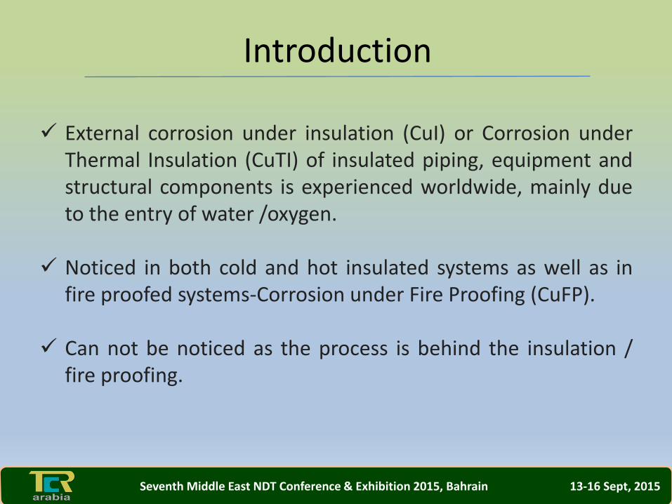
External corrosion under insulation (CuI) or Corrosion underThermal Insulation (CuTI) of insulated piping, equipment andstructural components is experienced worldwide, mainly dueto the entry of water /oxygen.
Noticed in both cold and hot insulated systems as well as infire proofed systems-Corrosion under Fire Proofing (CuFP).
Can not be noticed as the process is behind the insulation /fire proofing.
Introduction
Seventh Middle East NDT Conference & Exhibition 2015, Bahrain 13-16 Sept, 2015

Moisture into the insulation system may further• Carry the air borne pollutants/corrosive substances’• Water leaches out chlorides, other halides or sulphates leadingto corrosion.
• Punctures, slipped cladding, seal deterioration aid the easyentry of water into the insulation.
• Render the insulation ineffective. For example,1 vol.-% of waterin the insulation material leads to an approximate 4% increase inthe thermal conductivity. A water concentration of 5 vol.-% of theoverall insulation material’s volume, increases the l value by 20%.
Introduction
Seventh Middle East NDT Conference & Exhibition 2015, Bahrain 13-16 Sept, 2015
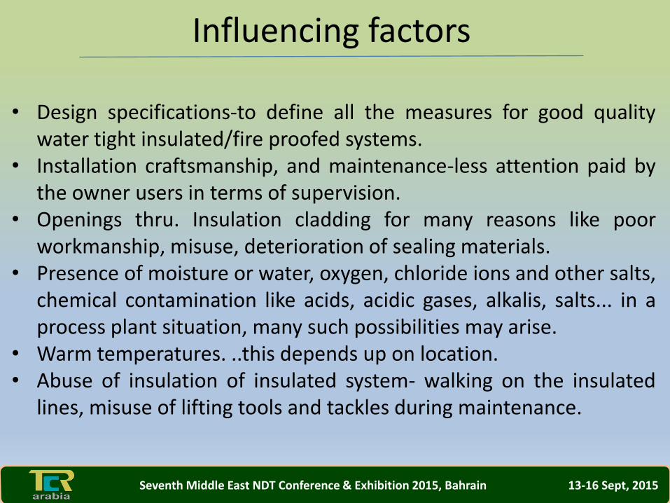
• Design specifications-to define all the measures for good qualitywater tight insulated/fire proofed systems.
• Installation craftsmanship, and maintenance-less attention paid bythe owner users in terms of supervision.
• Openings thru. Insulation cladding for many reasons like poorworkmanship, misuse, deterioration of sealing materials.
• Presence of moisture or water, oxygen, chloride ions and other salts,chemical contamination like acids, acidic gases, alkalis, salts... in aprocess plant situation, many such possibilities may arise.
• Warm temperatures. ..this depends up on location.• Abuse of insulation of insulated system- walking on the insulated
lines, misuse of lifting tools and tackles during maintenance.
Influencing factors
Seventh Middle East NDT Conference & Exhibition 2015, Bahrain 13-16 Sept, 2015
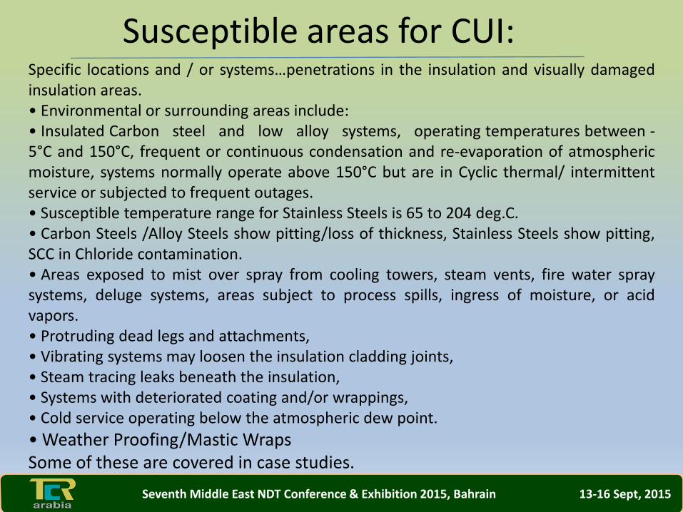
Specific locations and / or systems…penetrations in the insulation and visually damagedinsulation areas.• Environmental or surrounding areas include:• Insulated Carbon steel and low alloy systems, operating temperatures between -5°C and 150°C, frequent or continuous condensation and re-evaporation of atmosphericmoisture, systems normally operate above 150°C but are in Cyclic thermal/ intermittentservice or subjected to frequent outages.• Susceptible temperature range for Stainless Steels is 65 to 204 deg.C.• Carbon Steels /Alloy Steels show pitting/loss of thickness, Stainless Steels show pitting,SCC in Chloride contamination.• Areas exposed to mist over spray from cooling towers, steam vents, fire water spraysystems, deluge systems, areas subject to process spills, ingress of moisture, or acidvapors.• Protruding dead legs and attachments,• Vibrating systems may loosen the insulation cladding joints,• Steam tracing leaks beneath the insulation,• Systems with deteriorated coating and/or wrappings,• Cold service operating below the atmospheric dew point.
• Weather Proofing/Mastic WrapsSome of these are covered in case studies.
Susceptible areas for CUI:
Seventh Middle East NDT Conference & Exhibition 2015, Bahrain 13-16 Sept, 2015
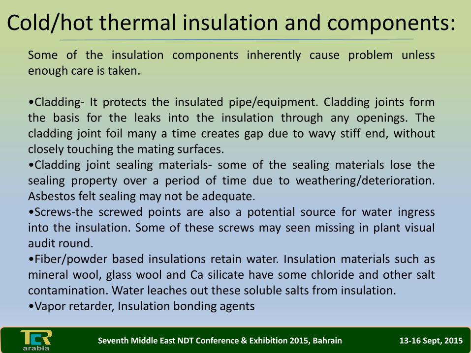
Some of the insulation components inherently cause problem unlessenough care is taken.
•Cladding- It protects the insulated pipe/equipment. Cladding joints formthe basis for the leaks into the insulation through any openings. Thecladding joint foil many a time creates gap due to wavy stiff end, withoutclosely touching the mating surfaces.•Cladding joint sealing materials- some of the sealing materials lose thesealing property over a period of time due to weathering/deterioration.Asbestos felt sealing may not be adequate.•Screws-the screwed points are also a potential source for water ingressinto the insulation. Some of these screws may seen missing in plant visualaudit round.•Fiber/powder based insulations retain water. Insulation materials such asmineral wool, glass wool and Ca silicate have some chloride and other saltcontamination. Water leaches out these soluble salts from insulation.•Vapor retarder, Insulation bonding agents
Cold/hot thermal insulation and components:
Seventh Middle East NDT Conference & Exhibition 2015, Bahrain 13-16 Sept, 2015
•Design aspectsspecification is the key to cover all the design aspects of InsulationMaterials, cladding, Heat-traced Systems, Protective Coatings andsealing, Shutdown/Mothballing, Quality Control/Quality Assuranceand follow.Some examples include:•Avoid creating inspection ports.•Select where possible insulation systems like Foam glass whichhold less water.•Old specifications did not call for protective coatings on thepipe/equipment/structural, before applying the insulation. Usecoatings to prevent corrosion due to the entry of moisture. CuTIresistant coatings are required for both cold and hot insulation7.Coatings for systems without insulation may not work for systemswith insulation
Prevention
Seventh Middle East NDT Conference & Exhibition 2015, Bahrain 13-16 Sept, 2015
InspectionOne of the important inspection requirements is to get the metalloss due to CuTI. For this first initial thickness is required.Baseline surveys are best carried out during the constructionphase, before applying coating and insulation. This helps in takingcorrective actions for components not meeting the specificationcan be readily done.
CuTI is difficult to identify and hence where to start is important.An account of susceptible areas can be used as a guide. Insulatedsystems are to be reviewed to identify periodic inspection forcritical areas to take corrective actions. The review is based on theprocess and mechanical data. Where possible, remove theinsulation on the critical areas for inspection.
Seventh Middle East NDT Conference & Exhibition 2015, Bahrain 13-16 Sept, 2015
Inspection
DP, Ultrasonic thickness measurements are commonly used,where the insulation is removed. In addition, advanced NDT isalso required.For CuTI inspection, Visual examination (for all cases ofwithout/local/full removal of insulation) helps in eliminatingmisinterpretation with other NDT.If inspection program is planned for multi plant complex, numberof insulated lines may be at least one lakh in addition tothousands of equipment.Removing insulation of all these lines even in small lengths, forinspection, would be highly laborious, time taking and costintensive.
Seventh Middle East NDT Conference & Exhibition 2015, Bahrain 13-16 Sept, 2015
Inspection
Large lengths of insulation removal mean that there is amaximum possibility of affecting the process. This restricts theinspection rate.Cryogenic insulation removal is not advisable during operationdue to ice formation.Hence, techniques to predict the condition of metal beneaththe insulation are required without its removal.
Seventh Middle East NDT Conference & Exhibition 2015, Bahrain 13-16 Sept, 2015

It is important to inspect insulated pipe work, equipment and structural to identifyCuTI/CuFP sites. One can detect hot/cold spots with at least 10 deg. C temperaturedifferential across the thickness of the Component.
It is a remote condition monitoring technique which identifies the presence ofmoisture through mapped surface temperatures. For some field applications, considerinfluencing factors such as changes in surface Emissivity, the affects of sunlight heat andother atmospheric effects.Ideally, Thermography should be done before rainy season and repeat at the endof the season and correlate.
Thermogram of carbon steel insulated line, showing wet patch
Advance NDT : Thermography
Seventh Middle East NDT Conference & Exhibition 2015, Bahrain 13-16 Sept, 2015
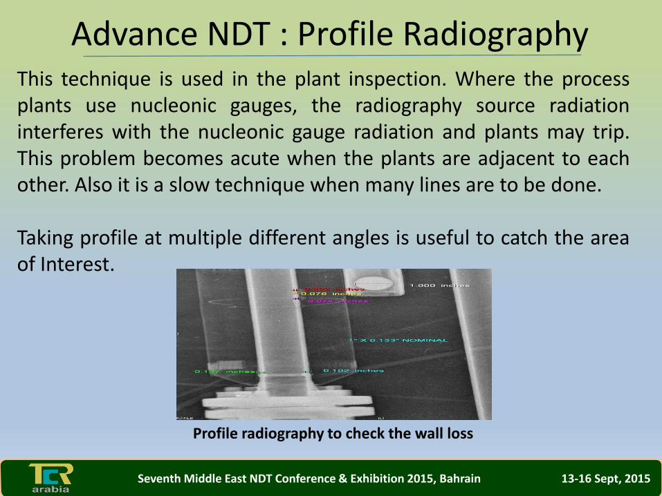
This technique is used in the plant inspection. Where the processplants use nucleonic gauges, the radiography source radiationinterferes with the nucleonic gauge radiation and plants may trip.This problem becomes acute when the plants are adjacent to eachother. Also it is a slow technique when many lines are to be done.
Taking profile at multiple different angles is useful to catch the areaof Interest.
Profile radiography to check the wall loss
Advance NDT : Profile Radiography
Seventh Middle East NDT Conference & Exhibition 2015, Bahrain 13-16 Sept, 2015
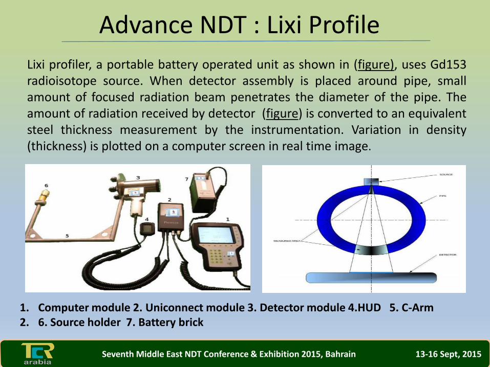
Lixi profiler, a portable battery operated unit as shown in (figure), uses Gd153radioisotope source. When detector assembly is placed around pipe, smallamount of focused radiation beam penetrates the diameter of the pipe. Theamount of radiation received by detector (figure) is converted to an equivalentsteel thickness measurement by the instrumentation. Variation in density(thickness) is plotted on a computer screen in real time image.
1. Computer module 2. Uniconnect module 3. Detector module 4.HUD 5. C-Arm 2. 6. Source holder 7. Battery brick
Advance NDT : Lixi Profile
Seventh Middle East NDT Conference & Exhibition 2015, Bahrain 13-16 Sept, 2015

Applications of Lixi Profiler include:
Pipe wall thinning, Corrosion under Insulation (CUI, PipeBlockages such as Bitumen, Ice, or any another foreign materialWet Insulation Cluster of Internal and external pitting, Wallthickness measurement on insulated or bare pipes w/ or w/oproduct, Wall thickness measurement on very hot pipes while in-service, Weld Identification on Insulated Piping Systems.The profiler can be used on hot permit system.
Advance NDT : Lixi Profile
Seventh Middle East NDT Conference & Exhibition 2015, Bahrain 13-16 Sept, 2015
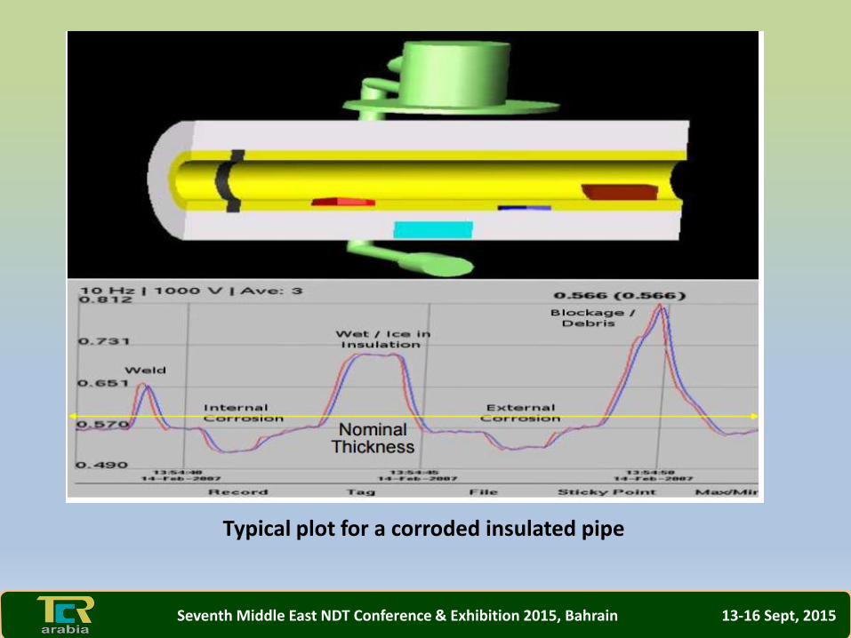
Typical plot for a corroded insulated pipe
Seventh Middle East NDT Conference & Exhibition 2015, Bahrain 13-16 Sept, 2015
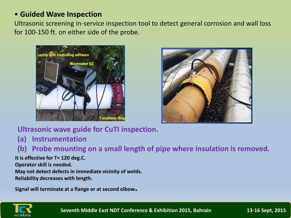
• Guided Wave InspectionUltrasonic screening in-service inspection tool to detect general corrosion and wall lossfor 100-150 ft. on either side of the probe.
Ultrasonic wave guide for CuTI inspection. (a) Instrumentation (b) Probe mounting on a small length of pipe where insulation is removed.
It is effective for T< 120 deg.C. Operator skill is needed. May not detect defects in immediate vicinity of welds. Reliability decreases with length.
Signal will terminate at a flange or at second elbow.
Seventh Middle East NDT Conference & Exhibition 2015, Bahrain 13-16 Sept, 2015

PEC is a noncontact type inspection technique for carbon steelobjects, such as pipes and vessels.It can measure % variations in steel thickness through any non-conductive and non-magnetic material between sensor and steelsurface such as air, insulation material, concrete, plastics,coatings, paint, sea water, marine growth deposits, oil etc.Electrical current flows through the transmitter coils of probe andgenerate a primary magnetic field. This field is unaffected by thepresence of any non-conducting and non-magnetic material andpenetrates undisturbed and magnetizes the top layer of the steelbeneath the transmitter coils.
Advance NDT : Pulsed Eddy Current (PEC)
Seventh Middle East NDT Conference & Exhibition 2015, Bahrain 13-16 Sept, 2015
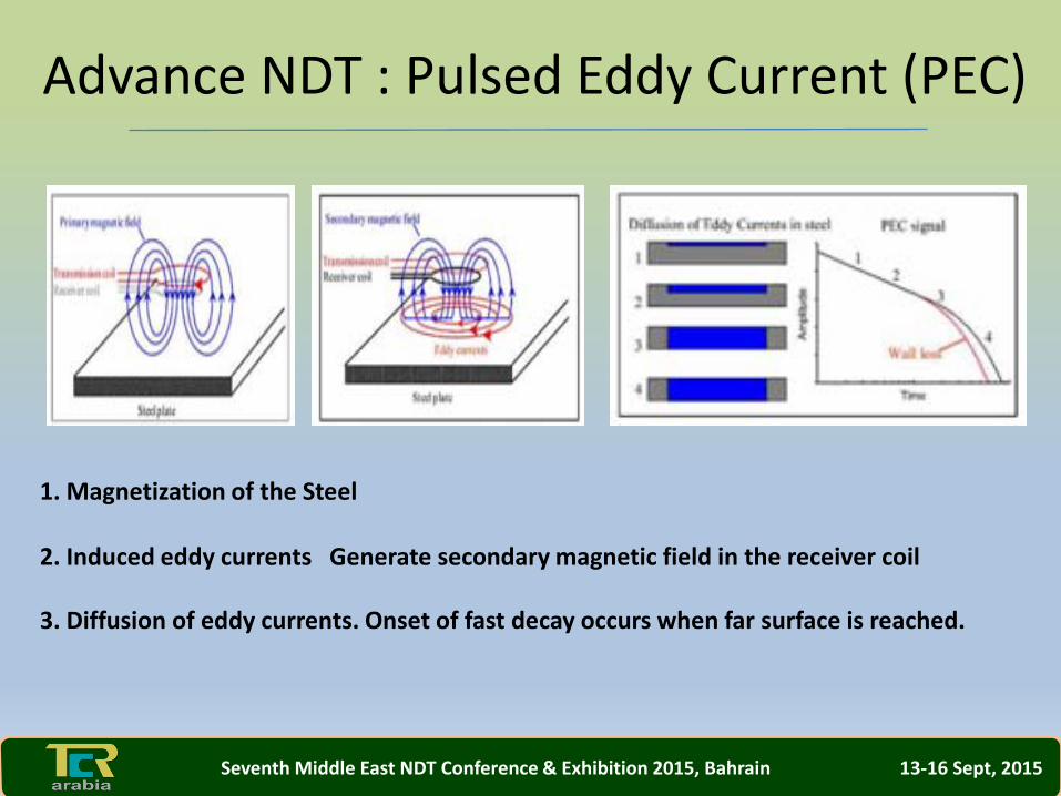
1. Magnetization of the Steel
2. Induced eddy currents Generate secondary magnetic field in the receiver coil
3. Diffusion of eddy currents. Onset of fast decay occurs when far surface is reached.
Advance NDT : Pulsed Eddy Current (PEC)
Seventh Middle East NDT Conference & Exhibition 2015, Bahrain 13-16 Sept, 2015

The current in the transmitter coil is switched off, collapsing the primary magnetic field.The changing magnetic field induces electrical ‘eddy’ currents in the surface of the steel.These eddy currents generate a secondary magnetic field and induces an electrical voltage,which in the receiver coils.The magnitude of this voltage as a function of the time is referred to as the ‘PEC signal’.
The PEC signal contains information about the thickness of the steel, as described below. Aspecimen has a near and a far surface. Initially the eddy currents are confined to the nearsurface (closest to the PEC probe) but, as time elapses, they travel (or ‘diffuse’) outwardstowards the far surface (figure 9). As long as the eddy currents experience free expansionin the wall, their strength decreases relatively slowly.
Advance NDT : Pulsed Eddy Current (PEC)
Seventh Middle East NDT Conference & Exhibition 2015, Bahrain 13-16 Sept, 2015
However, upon reaching the far surface, their strength decreases rapidly.The moment in time where the eddy currents first reach the far surface isindicated by a sharp decrease in PEC signal, known as ‘transition point’(figure 9). The time of the transition point is therefore a measure of wallthickness. For example, the earlier the transition point, the sooner theeddy currents reach the far surface and the thinner the wall must be. Inpractice, each time a PEC measurement is done; voltage across thereceiver coils of the PEC probe is amplified, sampled and digitized by thePEC instrument. This gives a digital record of the PEC signal over 3000sample moments in time. The digitized signals are stored in a connectedcomputer. Dedicated software is used to analyze the shape of all PECsignals and thereby determine wall thickness.
Advance NDT : Pulsed Eddy Current (PEC)
Seventh Middle East NDT Conference & Exhibition 2015, Bahrain 13-16 Sept, 2015
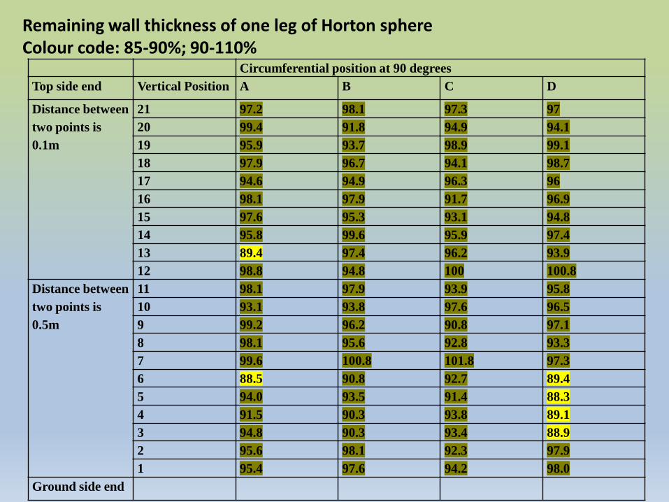
Circumferential position at 90 degrees
Top side end Vertical Position A B C D
Distance between
two points is
0.1m
21 97.2 98.1 97.3 97
20 99.4 91.8 94.9 94.1
19 95.9 93.7 98.9 99.1
18 97.9 96.7 94.1 98.7
17 94.6 94.9 96.3 96
16 98.1 97.9 91.7 96.9
15 97.6 95.3 93.1 94.8
14 95.8 99.6 95.9 97.4
13 89.4 97.4 96.2 93.9
12 98.8 94.8 100 100.8
Distance between
two points is
0.5m
11 98.1 97.9 93.9 95.8
10 93.1 93.8 97.6 96.5
9 99.2 96.2 90.8 97.1
8 98.1 95.6 92.8 93.3
7 99.6 100.8 101.8 97.3
6 88.5 90.8 92.7 89.4
5 94.0 93.5 91.4 88.3
4 91.5 90.3 93.8 89.1
3 94.8 90.3 93.4 88.9
2 95.6 98.1 92.3 97.9
1 95.4 97.6 94.2 98.0
Ground side end
Remaining wall thickness of one leg of Horton sphere Colour code: 85-90%; 90-110%
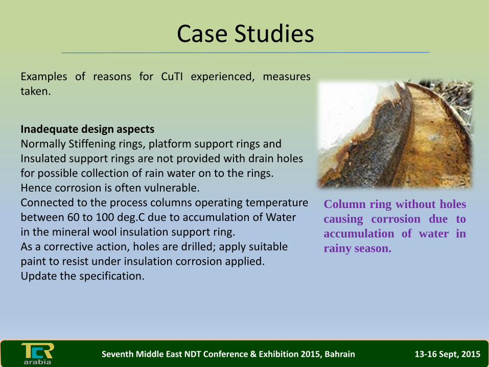
Examples of reasons for CuTI experienced, measurestaken.
Inadequate design aspectsNormally Stiffening rings, platform support rings andInsulated support rings are not provided with drain holesfor possible collection of rain water on to the rings.Hence corrosion is often vulnerable.Connected to the process columns operating temperaturebetween 60 to 100 deg.C due to accumulation of Waterin the mineral wool insulation support ring.As a corrective action, holes are drilled; apply suitablepaint to resist under insulation corrosion applied.Update the specification.
Column ring without holes
causing corrosion due to
accumulation of water in
rainy season.
Case Studies
Seventh Middle East NDT Conference & Exhibition 2015, Bahrain 13-16 Sept, 2015
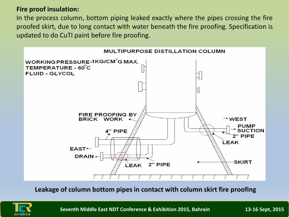
Fire proof insulation:In the process column, bottom piping leaked exactly where the pipes crossing the fireproofed skirt, due to long contact with water beneath the fire proofing. Specification isupdated to do CuTI paint before fire proofing.
Leakage of column bottom pipes in contact with column skirt fire proofing
Seventh Middle East NDT Conference & Exhibition 2015, Bahrain 13-16 Sept, 2015
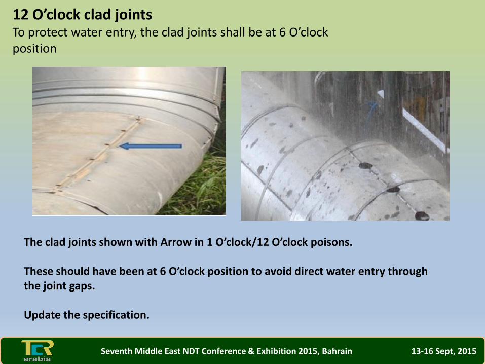
12 O’clock clad jointsTo protect water entry, the clad joints shall be at 6 O’clock position
The clad joints shown with Arrow in 1 O’clock/12 O’clock poisons.
These should have been at 6 O’clock position to avoid direct water entry through the joint gaps.
Update the specification.
Seventh Middle East NDT Conference & Exhibition 2015, Bahrain 13-16 Sept, 2015
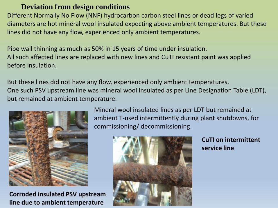
Deviation from design conditionsDifferent Normally No Flow (NNF) hydrocarbon carbon steel lines or dead legs of varied diameters are hot mineral wool insulated expecting above ambient temperatures. But these lines did not have any flow, experienced only ambient temperatures.
Pipe wall thinning as much as 50% in 15 years of time under insulation. All such affected lines are replaced with new lines and CuTI resistant paint was applied before insulation.
But these lines did not have any flow, experienced only ambient temperatures.One such PSV upstream line was mineral wool insulated as per Line Designation Table (LDT), but remained at ambient temperature.
Corroded insulated PSV upstream line due to ambient temperature
Mineral wool insulated lines as per LDT but remained at ambient T-used intermittently during plant shutdowns, for commissioning/ decommissioning.
CuTI on intermittent service line
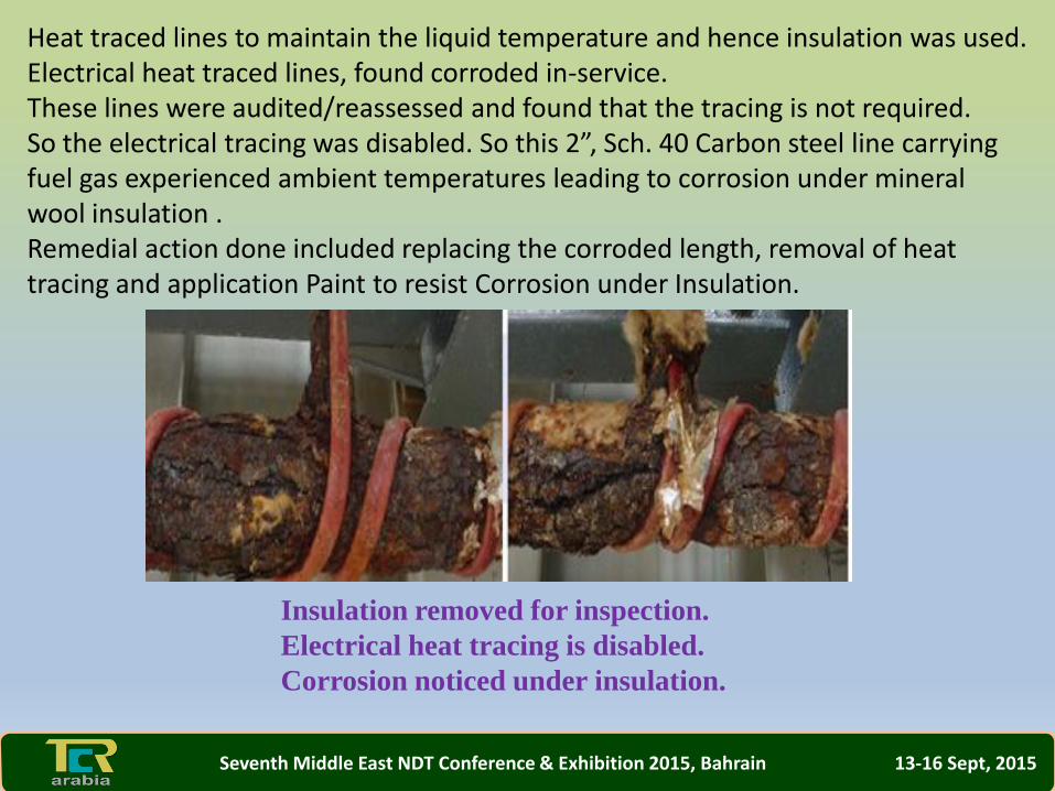
Heat traced lines to maintain the liquid temperature and hence insulation was used. Electrical heat traced lines, found corroded in-service. These lines were audited/reassessed and found that the tracing is not required. So the electrical tracing was disabled. So this 2”, Sch. 40 Carbon steel line carrying fuel gas experienced ambient temperatures leading to corrosion under mineral wool insulation . Remedial action done included replacing the corroded length, removal of heat tracing and application Paint to resist Corrosion under Insulation.
Insulation removed for inspection.
Electrical heat tracing is disabled.
Corrosion noticed under insulation.
Seventh Middle East NDT Conference & Exhibition 2015, Bahrain 13-16 Sept, 2015
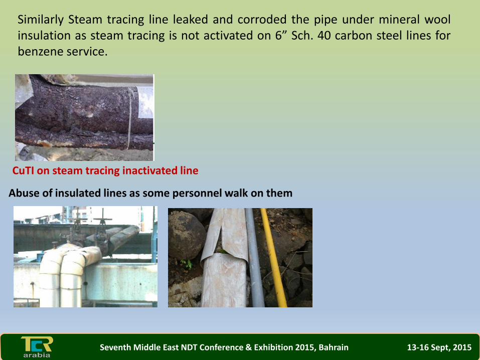
Similarly Steam tracing line leaked and corroded the pipe under mineral woolinsulation as steam tracing is not activated on 6” Sch. 40 carbon steel lines forbenzene service.
CuTI on steam tracing inactivated line
Abuse of insulated lines as some personnel walk on them
Seventh Middle East NDT Conference & Exhibition 2015, Bahrain 13-16 Sept, 2015
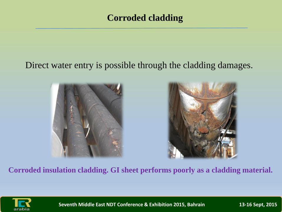
Corroded cladding
Direct water entry is possible through the cladding damages.
Corroded insulation cladding. GI sheet performs poorly as a cladding material.
Seventh Middle East NDT Conference & Exhibition 2015, Bahrain 13-16 Sept, 2015
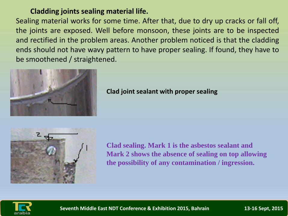
Cladding joints sealing material life. Sealing material works for some time. After that, due to dry up cracks or fall off,the joints are exposed. Well before monsoon, these joints are to be inspectedand rectified in the problem areas. Another problem noticed is that the claddingends should not have wavy pattern to have proper sealing. If found, they have tobe smoothened / straightened.
Clad joint sealant with proper sealing
Clad sealing. Mark 1 is the asbestos sealant and
Mark 2 shows the absence of sealing on top allowing
the possibility of any contamination / ingression.
Seventh Middle East NDT Conference & Exhibition 2015, Bahrain 13-16 Sept, 2015
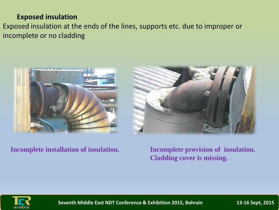
Exposed insulation Exposed insulation at the ends of the lines, supports etc. due to improper or incomplete or no cladding
Incomplete installation of insulation. Incomplete provision of insulation.
Cladding cover is missing.
Seventh Middle East NDT Conference & Exhibition 2015, Bahrain 13-16 Sept, 2015
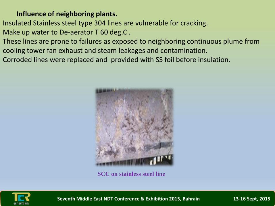
Influence of neighboring plants.Insulated Stainless steel type 304 lines are vulnerable for cracking.Make up water to De-aerator T 60 deg.C .These lines are prone to failures as exposed to neighboring continuous plume fromcooling tower fan exhaust and steam leakages and contamination.Corroded lines were replaced and provided with SS foil before insulation.
SCC on stainless steel line
Seventh Middle East NDT Conference & Exhibition 2015, Bahrain 13-16 Sept, 2015
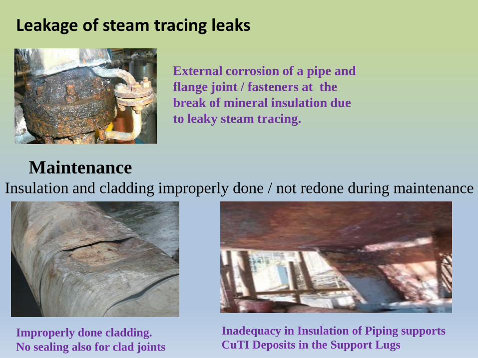
Leakage of steam tracing leaks
External corrosion of a pipe and
flange joint / fasteners at the
break of mineral insulation due
to leaky steam tracing.
MaintenanceInsulation and cladding improperly done / not redone during maintenance
Improperly done cladding.
No sealing also for clad joints
Inadequacy in Insulation of Piping supports
CuTI Deposits in the Support Lugs
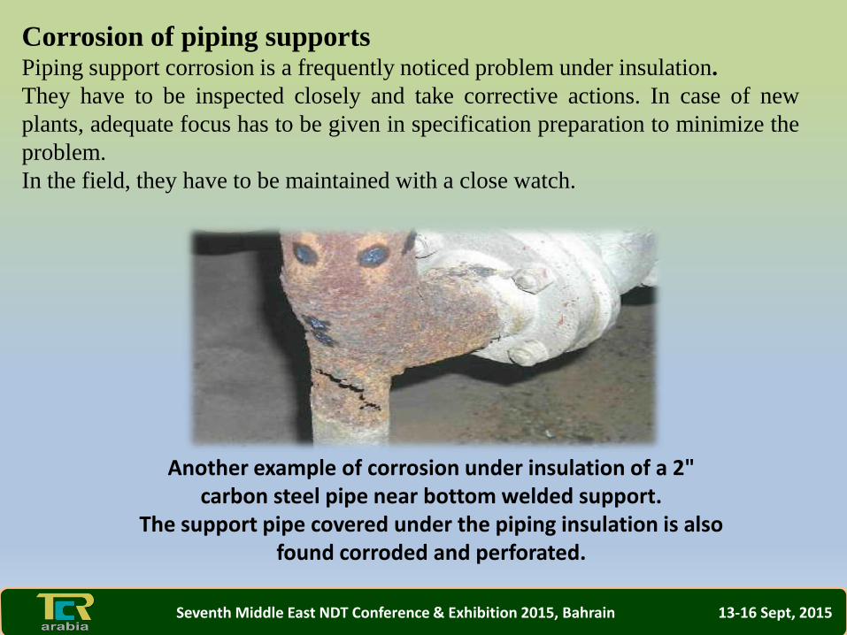
Corrosion of piping supportsPiping support corrosion is a frequently noticed problem under insulation.
They have to be inspected closely and take corrective actions. In case of new
plants, adequate focus has to be given in specification preparation to minimize the
problem.
In the field, they have to be maintained with a close watch.
Another example of corrosion under insulation of a 2" carbon steel pipe near bottom welded support.
The support pipe covered under the piping insulation is also found corroded and perforated.
Seventh Middle East NDT Conference & Exhibition 2015, Bahrain 13-16 Sept, 2015
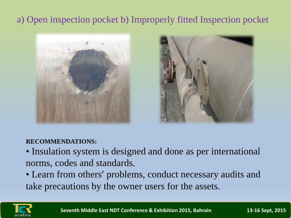
a) Open inspection pocket b) Improperly fitted Inspection pocket
RECOMMENDATIONS:
• Insulation system is designed and done as per international
norms, codes and standards.
• Learn from others’ problems, conduct necessary audits and
take precautions by the owner users for the assets.
Seventh Middle East NDT Conference & Exhibition 2015, Bahrain 13-16 Sept, 2015

Insulation system is designed and done as per international norms, codes and standards.
• Learn from others’ problems, conduct necessary audits and take precautions by the owner users for the assets.
Recommendations
Seventh Middle East NDT Conference & Exhibition 2015, Bahrain 13-16 Sept, 2015
The author thanks the organizers for accepting the paper for
presentation.
Acknowledgments
Seventh Middle East NDT Conference & Exhibition 2015, Bahrain 13-16 Sept, 2015