CORROSION PREVENTION AND CONTROL PLANNING...
74
CORROSION PREVENTION AND CONTROL PLANNING GUIDEBOOK (Spiral No. 1 – DECEMBER 2003) Issued by: PDUSD (AT&L) Director, Corrosion Policy and Oversight Downloaded from http://www.everyspec.com
-
Upload
truongphuc -
Category
Documents
-
view
241 -
download
3
Transcript of CORROSION PREVENTION AND CONTROL PLANNING...

CORROSION PREVENTION AND CONTROL PLANNING GUIDEBOOK
(Spiral No. 1 – DECEMBER 2003) Issued by: PDUSD (AT&L) Director, Corrosion Policy and Oversight
Downloaded from http://www.everyspec.com

Report Documentation Page Form ApprovedOMB No. 0704-0188
Public reporting burden for the collection of information is estimated to average 1 hour per response, including the time for reviewing instructions, searching existing data sources, gathering andmaintaining the data needed, and completing and reviewing the collection of information. Send comments regarding this burden estimate or any other aspect of this collection of information,including suggestions for reducing this burden, to Washington Headquarters Services, Directorate for Information Operations and Reports, 1215 Jefferson Davis Highway, Suite 1204, ArlingtonVA 22202-4302. Respondents should be aware that notwithstanding any other provision of law, no person shall be subject to a penalty for failing to comply with a collection of information if itdoes not display a currently valid OMB control number.
1. REPORT DATE 17 DEC 2003 2. REPORT TYPE
3. DATES COVERED 00-00-2003 to 00-00-2003
4. TITLE AND SUBTITLE Corrosion Prevention and Control Planning Guidebook
5a. CONTRACT NUMBER
5b. GRANT NUMBER
5c. PROGRAM ELEMENT NUMBER
6. AUTHOR(S) 5d. PROJECT NUMBER
5e. TASK NUMBER
5f. WORK UNIT NUMBER
7. PERFORMING ORGANIZATION NAME(S) AND ADDRESS(ES) Department of Defense,Principal Deputy Under Secretary of Defense,Acquisition, Technology and ,Logistics,Washington,DC,20301
8. PERFORMING ORGANIZATIONREPORT NUMBER
9. SPONSORING/MONITORING AGENCY NAME(S) AND ADDRESS(ES) 10. SPONSOR/MONITOR’S ACRONYM(S)
11. SPONSOR/MONITOR’S REPORT NUMBER(S)
12. DISTRIBUTION/AVAILABILITY STATEMENT Approved for public release; distribution unlimited
13. SUPPLEMENTARY NOTES
14. ABSTRACT
15. SUBJECT TERMS
16. SECURITY CLASSIFICATION OF: 17. LIMITATION OF ABSTRACT Same as
Report (SAR)
18. NUMBEROF PAGES
73
19a. NAME OFRESPONSIBLE PERSON
a. REPORT unclassified
b. ABSTRACT unclassified
c. THIS PAGE unclassified
Standard Form 298 (Rev. 8-98) Prescribed by ANSI Std Z39-18
Downloaded from http://www.everyspec.com

i
FORWARD
The purpose of this document is to provide acquisition program managers with guidance in developing and implementing a Corrosion Prevention and Control Program for DoD weapon systems and infrastructure, and corrosion related technical aspects that should be addressed for a viable design. This guidance is in accordance with DoD Corrosion Prevention and Control Policy Letter, signed by Acting USD (AT&L) and dated Nov 12, 2003 (Appendix A).
The cost of corrosion to the Department of Defense (DoD) is many billions of dollars annually. Congress has recognized this and enacted 10. U.S.C. 2228 which places added emphasis in the Department of Defense management and technical focus on corrosion prevention and control. DoD Directive 5000.1 , The Defense Acquisition System, states that corrosion prevention control and mitigation will be considered during life-cycle cost trade-offs. Operational capabilities such as readiness, reliability, sustainability, safety, etc. are already considered critical for an effective system and are usually addressed during conceptual design. This is also the point when the effects of corrosion on these capabilities should be addressed. Corrosion is a long term issue that usually impacts system operation some time after the system is procured, but the best time to effectively combat the effect of corrosion is early in system development. There is a false common belief that corrosion prevention and mitigation can be reverse engineered into the system later in the operational life cycle. The fact is that corrosion can have a significant impact on operational readiness and safety both by itself and in conjunction with other damage phenomena, and its interactions with these factors should be considered during the conceptual design phase.
National priorities dictate the need for much longer service lives for DoD systems. Since history indicates that the effects of corrosion increase with system age, this amplifies the need to consider corrosion prevention as a primary design parameter. As a consequence, the original design should include the best materials and manufacturing processes. The only way to assure effective, across-the-board response to this need to prevent or severely reduce corrosion and its effects is to establish a standard DoD corrosion control philosophy and methodology through which acquisition program managers can initiate and execute plans and actions that result in satisfactory materials and processes.
Downloaded from http://www.everyspec.com
ii
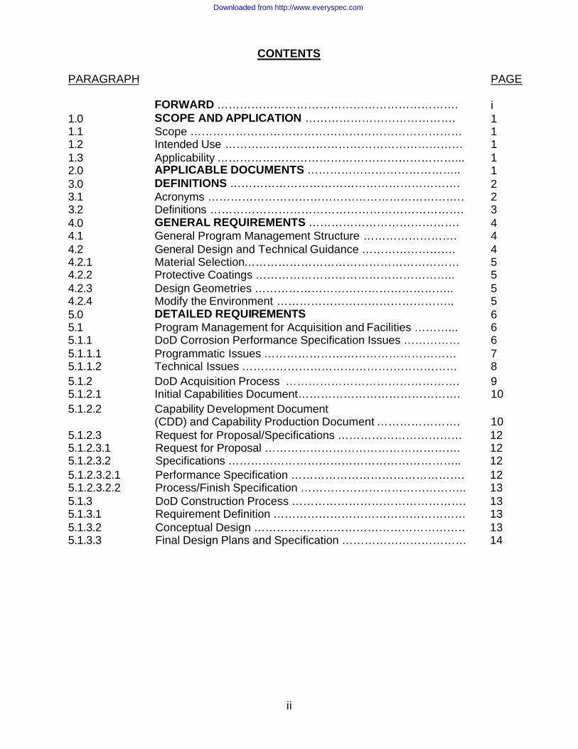
CONTENTS
5.1.2.3 5.1.2.3.1 5.1.2.3.2
Request for Proposal/Specifications …………………………… Request for Proposal ……………………………………………. Specifications ……………………………………………………..
12 12 12
5.1.2.3.2.1 5.1.2.3.2.2 5.1.3
Performance Specification ………………………………………. Process/Finish Specification …………………………………….. DoD Construction Process ……………………………………….
12 13 13
5.1.3.1 5.1.3.2 5.1.3.3
Requirement Definition …………………………………………… Conceptual Design ……………………………………………….. Final Design Plans and Specification ……………………………
13 13 14
PARAGRAPH PAGE 1.0 1.1 1.2 1.3
FORWARD ………………………………………………………. SCOPE AND APPLICATION …………………………………. Scope ……………………………………………………………… Intended Use ……………………………………………………… Applicability ………………………………………………………...
i 1 1 1 1
2.0 APPLICABLE DOCUMENTS ………………………………….. 1 3.0 3.1 3.2
DEFINITIONS ……………………………………………………. Acronyms ………………………………………………………….. Definitions ………………………………………………………….
2 2 3
4.0 4.1 4.2 4.2.1 4.2.2 4.2.3 4.2.4
GENERAL REQUIREMENTS …………………………………. General Program Management Structure ……………………. General Design and Technical Guidance ……………………. Material Selection………………………………………………… Protective Coatings …………………………………………….. Design Geometries …………………………………………….. Modify the Environment ………………………………………..
4 4 4 5 5 5 5
5.0 5.1 5.1.1 5.1.1.1 5.1.1.2
DETAILED REQUIREMENTS Program Management for Acquisition and Facilities ………... DoD Corrosion Performance Specification Issues …………… Programmatic Issues …………………………………………… Technical Issues …………………………………………………
6 6 6 7 8
5.1.2 5.1.2.1
DoD Acquisition Process ………………………………………. Initial Capabilities Document…………………………………….
9 10
5.1.2.2
Capability Development Document (CDD) and Capability Production Document ………………….
10
Downloaded from http://www.everyspec.com

iii
PARAGRAPH CONTENTS PAGE
5.1.3.4 5.1.3.5 5.1.4
Request for Proposal ………………………………………….. Specifications …………………………………………………… Corrosion Prevention and Control Planning ………………….
14 14 14
5.1.4.1 5.1.4.1.1 5.1.4.1.2 5.1.4.1.3 5.1.4.2 5.1.4.2.1 5.1.4.2.2 5.1.5 5.1.5.1 5.1.5.2 5.1.5.3 5.2.5.4 5.1.5.5 5.2
Corrosion Prevention Advisory Team (CPAT) ………………. Establishment and Scope ……………………………………… Membership ……………………………………………………. CPAT Duties ……………………………………………………. Contractor Corrosion Team (CCT) …………………………... Membership ……………………………………………………… CCT Duties………………………………………………………. Corrosion Prevention and Control Planning Documentation... Corrosion Prevention and Control Plan (CPCP) ……………. Process/Finish Specification or Equivalent Document in Acquisition ……………………………………………………… System Verification Plan in Acquisition ……………………… Construction Inspection Plan for Facilities ………………………………………………………… Corrosion Technical Manual Guidance and Corrosion Maintenance Concept ……………………….. Design of Facilities …………………………………………….. APPENDICES: A. PDUSD (AT&L) Policy Letter ……………………………….. B. Example of Corrosion Prevention and Control Plan for Systems/Equipment ………………………………………….. C. Example of Corrosion Prevention and Control Plan for Facilities/Infrastructure ……………… D. Example of Charter for Corrosion Prevention and Control Team (CPAT) ……………………………………………….. E. Facilities/Infrastructure Design Guidance …………………
14 14 14 15 15 15 15 16 16 17 17 18 18 18 19 20 21 41 63 67
Downloaded from http://www.everyspec.com

1
1.0 SCOPE AND APPLICATION 1.1 Scope This document establishes the requirements for materials, processes, techniques, and tasks required to integrate an effective corrosion prevention and control program during all phases of DoD weapon systems and infrastructure development. The intent is to minimize the impact of corrosion on life cycle cost, readiness, reliability, supportability, safety and structural integrity. 1.2 Intended Use This document provides tools and techniques for implementing sound materials/processes selection practices and finish treatments during all phases of DoD weapon systems and infrastructure development. The content of this document is based on broad, in-depth military and industry experience regarding protection of weapons systems and infrastructure from corrosion and its effects. The document provides guidance on program management that can be implemented in organizations to address corrosion issues and develop corrosion control plans. Specifically, it describes requirements and methods for establishing and managing a Corrosion Prevention Advisory Team (CPAT) that is appropriately integrated into all design Integrated Product Teams (IPTs) (where applicable); and for developing and implementing a Corrosion Prevention and Control Plan (CPCP) as described in this document. 1.3 Applicability This guide is applicable for use by all DoD procuring activities and their respective contractors involved in the design, procurement, and upgrades of DoD systems. The detailed CPCP and the process/finish specification apply to all elements of DoD systems, including spare parts. This guidance, when used in conjunction with supportability, reliability, maintainability, structural integrity programs and applicable specific technical guidance will result in reliable DoD systems having a good balance between acquisition costs and life cycle cost. 1.4 Policy/Guidance The CPC Policy (Appendix A) requires that the effects of corrosion are objectively evaluated as part of program design and development activities and the inevitable trade-offs made through an open and transparent assessment of alternatives. This requirement is to be specifically addressed during the earliest phases of the acquisition process and by decision authorities at every level. It also establishes the need for Corrosion Prevention and Control Planning for programs subject to Defense Acquisition Board (DAB) Review. 2.0 APPLICABLE DOCUMENTS There are many documents which define nearly every aspect of corrosion definition, prevention and control. Some are current documents, while others have been either cancelled or neglected for many years. Regardless of their status , corrosion-related documents from government, industry, other non-government, and standards organizations will be available on the DoD Corrosion Exchange website www.DoDcorrosionexchange.org .
Downloaded from http://www.everyspec.com

2
3.0 DEFINITIONS For terms not defined below, refer to http://www.dau.mil/pubs/glossary/preface.asp website. 3.1 Acronyms AFCESA Air Force Civil Engineering Support Agency AFI Air Force Instruction AFP Air Force Pamphlet AFPD Air Force Policy Directive AFRL Air Force Research Laboratory AMMTIAC Advanced Materials, Manufacturing, and Testing Information Analysis Center
(new name for AMPTIAC – change to occur approx. mid-CY04) AMPTIAC Advanced Materials and Processes Technology Information Analysis Center AS Allowable Standard CDD Capabilities Development Document CCT Contractor Corrosion Team CFR Code of Federal Regulations CPAT Corrosion Prevention Advisory Team CPC Corrosion Prevention and Control CPCP Corrosion Prevention and Control Plan CPD Capabilities Production Document DAB Defense Acquisition Board DID Data Item Description DoD Department of Defense DSN Defense Switching Network DTIC Defense Technical Information Center EM Engineering Manual ETL Engineering Technical Letters EPA Environmental Protection Agency ESCO Engineering Services Company ESPC Energy Savings Performance Contracting FOC Full Operational Capability FRP Full Rate Production HQ Headquarters ICD Initial Capabilities Document IIPT Integrating IPT IOC Initial Operational Capability IPT Integrated Product Team IWT Industrial Waste Treatment LRIP Low Rate Initial Production M&P Materials and Processes MRB Material Review Board MTBF Mean Time Between Failure MTTR Mean Time To Repair MNS Mission Needs Statement NACE National Association of Corrosion Engineers
Downloaded from http://www.everyspec.com

3
NDI Non-destructive Inspection NEPA National Environmental Policy Act ORD Operational Requirements Document OT&E Operational Test and Evaluation PM Program Manager QA Quality Assurance R&D Research and Development RCS Report Control Symbol RFP Request for Proposal RM&S Reliability, Maintainability, and Supportability RP Recommended Practice SDD System Development and Demonstration SSPC Society of Protective Coatings TM Technical Manual T.O. Technical Order TPC Technical Practices Committee TR Technical Report USAF United States Air Force U.S.C. United States Code UST Underground Storage Tanks 3.2 Definitions Corrosion – is the deterioration of a material or its properties due to the reaction of that material with its chemical environment. Corrosion Prevention and Control - the rigorous application of engineering design and analysis, quality assurance (QA), nondestructive inspection (NDI), manufacturing, operations and support technologies to prevent the initiation of corrosion, avoid functional impairment due to corrosion, and define processes for the tracking and repair of corrosion problems. Integrated Product Team (IPT) - IPTs are an integral part of the defense acquisition oversight and review process, and are the primary means for organizations to be involved in acquisition programs. The lowest level of IPT is the Program IPT and is usually formed to serve a program or project at the program office level. When the term IPT appears in this document, it refers to the Program IPT unless otherwise indicated. For ACAT I programs, there are generally two more levels of IPT: the Overarching IPT (OIPT) and at least one Working-level IPT (WIPT). WIPTs shall focus on a particular topic such as cost/performance, test, or contracting . An Integrating IPT (IIPT) is a WIPT that functions as an integrator across the multi-program, cross-cutting characteristics of corrosion prevention and control. The IIPT shall coordinate other WIPT efforts and cover all topics not assigned to another IPT.
Downloaded from http://www.everyspec.com

4
4.0 GENERAL REQUIREMENTS 4.1 General Program Management Structure Program managers and procuring agencies should consider corrosion prevention and control (CPC) as a key issue in designing, procuring and maintaining a DoD system or facility. CPC planning features two aspects: (1) management of the planning, and (2) technical and design considerations (requirements, tradeoffs, etc.) that lead to viable CPC planning. These two basic aspects should be embedded in any viable DoD CPC planning whether it is associated with a weapon system or infrastructure. While implementation methods and procedures will vary with the system being procured and the responsible service or agency, it is critical to respond to the intent of these two aspects of viable CPC planning. The Corrosion Prevention and Control Plan (CPCP) should be prepared as early in a program/project as possible, but in the case of weapons systems, no later than Milestone B – Program Initiation, at which time the Program Manager should generate the document. The plan should define CPC requirements; list applicable specifications and standards; and address facility or system definition, design, engineering development, production/construction and sustainment phases, consistent with the design life and affordability of the system. It should also establish the management structure to be used for the peculiar system/facility being designed, procured and maintained, including a Corrosion Prevention Advisory Team (CPAT). The CPCP will dictate the membership and organization of the CPAT, describe basic duties of team members, define operating procedures, and prescribe appropriate specifications and standards used in the systems/facilities. The service laboratories may be able to provide added technical guidance. Similarly, AMPTIAC, where appropriate, may be able to assist in the preparation of CPCPs and provide direct support through the CPAT. The Program Manager will implement the CPCP with an accompanying process/finish specification and organize the CPAT. The process/finish specification (materials and processes for corrosion prevention and control) will specify the detailed finish and coating systems to be used on the weapon system being procured, in accordance with CPCP approved process/finish specifications and standards. 4.2 General Design and Technical Guidance A primary consideration in the design and construction of DoD weapons systems or facilities is the proper blending of safety, affordability, and environmental needs with mission and operational requirements. DoD systems or facilities are expected to perform reliably, require minimum maintenance over a specified lifetime, and deteriorate at rate that permits maximum service life. Therefore, materials, manufacturing methods and protective treatments which reduce failures due to deterioration should be considered during the process of selecting suitable materials and appropriate manufacturing methods that will satisfy system requirements. Deterioration modes which contribute to failures include, but are not limited to, pitting corrosion, galvanic corrosion, exfoliation corrosion, stress corrosion, corrosion fatigue, thermal embrittlement, fretting fatigue, oxidation, hydrogen embrittlement, weathering and fungus growth. Much background information and directed research may be available through AMPTIAC. In the entire design phase, attention should be given to precautionary measures to minimize deterioration of individual parts and assemblies as
Downloaded from http://www.everyspec.com

5
well as the entire system. Precautionary measures are included in the following paragraphs. The CPCP and program/project specifications should detail specific requirements. Fundamentally, the design should attempt to eliminate corrosive contaminants. If materials are expected to be exposed to contaminants, select design geometries, materials, manufacturing processes, and coatings that prevent or control corrosion. Selected design disciplines should enable designers to evaluate the following general approaches to design: selecting the right materials and manufacturing processes, applying protective coatings as necessary, using proper corrosion preventative and control designs, and modifying the environment. 4.2.1 Material Selection If possible , avoid materials that are unsuitable to the operational environment. Consider compatibility when using multiple materials. If dissimilar materials cannot be avoided, isolate those materials from each other. 4.2.2 Protective Coatings Protective coatings should be considered to isolate vulnerable materials from the environment. 4.2.3 Design Geometries Avoid crevices when possible. Avoid design features that make it difficult for protective coatings to function (sharp corners, for instance). Avoid geometries that unnecessarily trap moisture. 4.2.4 Modify the Environment When it is necessary for a portion of the system to be exposed to the environment, consider a design which allows for the modification of the environment to which materials will be exposed. Dehumidification and sheltering can be effective means for modifying the environment.
Downloaded from http://www.everyspec.com
6
5.0 DETAILED REQUIREMENTS 5.1 Program/Project Management for Acquisition and Facilities Corrosion Prevention and Control Planning applies to systems covered primarily by the DoD 5000-series publications, and to the facilities and infrastructure community. The need for viable CPC planning in both communities is critical to program/project success. This section is applicable to both types of programs/projects. If specific procedures apply to only one type of program or project, clearly annotated guidance is provided for that particular community. The various aspects of effective and viable CPC planning should be smoothly and seamlessly integrated. The initial phases of the acquisition cycle should consider the effects of corrosion on the system and reflected in the appropriate documents. For the system acquisition community, the requirements need to be reflected in the Initial Capabilities Document (ICD), Capability Development Document (CDD) and Capability Production Document (CPD). The program manager and the prime contractor should translate the requirements into a Request for Proposal (RFP), Performance Specifications, and CPC planning. For the facilities community, the construction team, particularly the project manager and the prime contractor, should translate the requirements into a Request for Proposal (RFP), Final Designs and Plans, Contract Specifications, and CPC planning. CPC planning itself has several aspects. First and foremost, the Corrosion Prevention and Control Plan (CPCP) should be integral to and eventually the result of the contract. The CPCP describes how the particular program/project will implement CPC planning. When developing a system, the CPCP should reflect the establishment of the Corrosion Prevention Advisory Team (CPAT), the development of a process/finish specification, and environmental test and verification plans and regimens to assure corrosion prevention and control at the component and assembly levels as well as at the system level. It should also provide guidance for development of corrosion technical manuals and maintenance concepts. When developing a facility, the CPCP should reflect the formation of the Corrosion Prevention Advisory Team (CPAT), the integration of corrosion prevention into the project design and plans, and provisions for the inspection of coatings and cathodic protection during construction. 5.1.1 DoD Corrosion Performance Specification Issues For more than a decade, the Federal Government, and especially the Department of Defense (DoD), has attempted to streamline the acquisition process. Acquisition reform has caused a shift from application of traditional military specifications, standards and handbooks to more reliance on commercial and performance specifications. This shift presents opportunities and challenges for the Program/Project Managers and their engineers. One of the many challenges facing the Program/Project/Engineering Manager/Designer is the ability to develop a meaningful performance specification for corrosion.
Downloaded from http://www.everyspec.com

7
There are several issues to be considered for effective implementation of corrosion performance specifications in DoD acquisition/construction programs/projects. These issues can be broken into “programmatic” and “technical” categories. 5.1.1.1 Programmatic Issues Programmatic issues are those which arise as a result of the DoD acquisition process. These include:
a. Acquisition Cost – Implementing effective corrosion control which reduces lifecycle cost may increase the new unit procurement/construction cost. As a result, the program/project manager should balance the cost of improved design for corrosion against the life cycle costs for the system/facility. This may be difficult unless objective measures of effectiveness for corrosion control considerations are established.
b. Warranties – Warranties are widely used in commercial and private
procurements. Although the terms vary widely, essentially the seller assures the buyer that the product will perform as represented over a period of time. If the product fails to perform as represented, the seller may be required to provide a new product, to fix the existing product, etc. These agreements are typically hard to enforce (though there may be exceptions) with respect to corrosion in DoD procurements for three reasons. First, a warranty is of little value in a critical situation. If a fire control system fails in service due to corrosion in an electrical connector, the fact that it can be replaced or repaired by the manufacturer at little or no cost to the Government is of little consequence to the US or allied personnel under fire. Or if a deluge tank in a fire protection system fails due to the failure of a corroded valve or pump, the fact that it can be replaced or repaired by the manufacturer at little or no cost to the Government is of little consequence when the failure has resulted in property damage, personnel injury, or mission capability degradation. Second, the terms of such agreements are often complex. This may result in burdensome record keeping and may constrain DoD’s flexibility with respect to maintenance procedures. Finally, the terms can also be somewhat subjective. This is not an issue when an item or component fails to perform its intended function due to corrosion (such as the examples mentioned above). However, it is a significant issue when corrosion impacts appearance and objective measures of performance are not available. Unfortunately in the past, many corrosion maintenance actions were considered discretionary until system functionality was actually affected. However, maintenance concepts and reliability considerations do not allow for deterioration to the point of functional failure.
c. Priority of Corrosion Control in Acquisition/Construction – DoD
programs/projects typically focus on implementing a tactical or strategic capability, or meeting defined requirements within budgetary constraints. While logistics support has long been recognized as a critical aspect of any procurement, the life cycle costs incurred as a result of corrosion have only recently received substantial attention. Still, the significant life cycle cost reduction achieved by implementing strong CPC planning doesn’t often receive sufficient priority when the program/project manager must deliver a product within stringent budgetary constraints.
Downloaded from http://www.everyspec.com

8
5.1.1.2 Technical Issues Technical issues for consideration in the implementation of effective corrosion performance specifications include:
a. Variables Influencing Corrosion – Susceptibility to corrosion is influenced by the interrelationships between materials and their specific environments. These interrelationships are impacted by design (including configuration and coatings), manufacture or construction, operation, and maintenance. As a result, corrosion performance is both an attribute of an entire system or facility and the sum of the performance of components or individual items. Corrosion performance specifications for complex systems should be addressed beginning at the component or item level. Corrosion performance specifications for facilities should be addressed beginning at the conceptual design level. Since design and configuration also influence corrosion performance, these issues should be addressed as well.
b. Potential Solutions to Corrosion Problems – The large number of variables which influence corrosion performance lead to a large number of potential solutions, some of which might not be compatible. As emphasized earlier in this document, a thorough review of relevant technical literature is essential for making informed decisions when specifying corrosion performance requirements. Therefore, written corrosion specifications should be sufficiently flexible to allow the designer and manufacturer to consider the entire range of potential solutions.
c. Assessments of Corrosion Impacts In Acquisition – Accurate assessment of the impact of corrosion is difficult since corrosion affects both function and appearance. The potential loss of function due to corrosion can many times be quantified through physical measurements. These may include plating, thickness loss, pit depth measurements, torque measurements and conductivity measurements. However, quantitative assessments are costly and, as a result, are typically applied to critical items only. In addition, hidden corrosion is difficult to detect and is a major issue. Degradation in appearance is typically evaluated in very subjective terms through comparison with visual standards such as those specified in technical manuals and technical society standards. Thus, methods and equipment for corrosion monitoring and inspection should be considered in the development of design and maintenance concepts.
d. Accelerated Corrosion Tests in Acquisition – Although the corrosion science
and engineering community has been working on developing accelerated tests for a long time, corrosion is a time-based phenomena and correlations between accelerated corrosion tests and service performance cannot always be determined. Although some tests claim to be predictive in nature (i.e. exposure of X hours in test simulates Y years of service life), exact correlations cannot be made. Accelerated tests are therefore most useful for ranking the relative performance of materials, coatings, etc. in a specific environment and application in comparison to a known system. Many times they do not adequately reflect the effects of design changes, substantial material changes, and maintenance cycles. Environmental test and verification planning should be designed to duplicate both the levels and types of damage expected from the environmental spectrum defined for the system. This may be achieved by a combination of
Downloaded from http://www.everyspec.com
9
environmental tests which capture the critical aspects of the exposure such as wet/dry cycles, specific corrodents, geometric configurations, etc. Accelerated corrosion testing, in conjunction with mechanical testing, should provide insight into the capabilities of the protective systems as well as allowing projections of damage growth in order to facilitate corrosion management.
e. Inspection and Testing on Facilities – The inspection and testing of facility
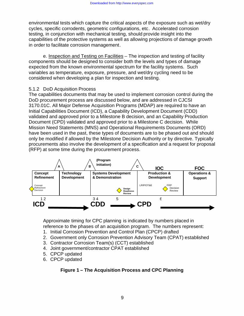
components should be designed to consider both the levels and types of damage expected from the known environmental spectrum for the facility systems. Such variables as temperature, exposure, pressure, and wet/dry cycling need to be considered when developing a plan for inspection and testing. 5.1.2 DoD Acquisition Process The capabilities documents that may be used to implement corrosion control during the DoD procurement process are discussed below, and are addressed in CJCSI 3170.01C. All Major Defense Acquisition Programs (MDAP) are required to have an Initial Capabilities Document (ICD), a Capability Development Document (CDD) validated and approved prior to a Milestone B decision, and an Capability Production Document (CPD) validated and approved prior to a Milestone C decision. While Mission Need Statements (MNS) and Operational Requirements Documents (ORD) have been used in the past, these types of documents are to be phased out and should only be modified if allowed by the Milestone Decision Authority or by directive. Typically procurements also involve the development of a specification and a request for proposal (RFP) at some time during the procurement process.
Approximate timing for CPC planning is indicated by numbers placed in reference to the phases of an acquisition program. The numbers represent: 1. Initial Corrosion Prevention and Control Plan (CPCP) drafted 2. Government only Corrosion Prevention Advisory Team (CPAT) established 3. Contractor Corrosion Team(s) (CCT) established 4. Joint government/contractor CPAT established 5. CPCP updated 6. CPCP updated
Figure 1 – The Acquisition Process and CPC Planning
Concept Refinement Concept Refinement Decision
Technology Development
Systems Development & Demonstration
Production & Development LRIP/OT&E FRP Decision Review
Operations & Support
IOC FOC
Design Readiness Review
(Program Initiation)
ICD CDD CPD
A B C
1 2 3 4 5 6
Downloaded from http://www.everyspec.com

10
5.1.2.1 Initial Capabilities Document The ICD establishes the need for a materiel approach to resolve a specific capability gap. The ICD defines the capability gap in terms of the of the functional area(s), the relevant range of military operations, time, obstacles to overcome and key attributes with appropriate measures of effectiveness, e.g., distance effect (including scale), etc,. The ICD proposes the recommended materiel approach(s) based on analysis of the relative cost, efficacy, sustainability, environmental quality impacts and risk posed by the materiel approach(s) under consideration. Once approved, an ICD is not normally updated. The Capability Development Document (CDD) and Capability Production Document (CPD) continue to refine the materiel approach to address the capability gap. Since these documents describe top level capability gaps and identify top level alternatives, corrosion-related wording should be kept at a similar level. Most importantly, the expected operational environment as it pertains to corrosivity should be clearly identified. This document should discuss whether corrosion (either through cost or impact on readiness) played a role in creating a deficiency. Consider the corrosion-related wording presented below:
• Existing systems have been unable to meet required maintenance periodicity as a result of corrosion;
• Corrosion occurring on existing systems places a large cost and labor-hour burden on the maintenance infrastructure;
• Excessive corrosion on existing systems has resulted in reduced readiness. • The system is expected to operate under severe operational and environmental
conditions. The system should be supportable within the current accepted maintenance concept. The system maintenance should be performed in compliance with Environmental Protection Agency guidelines in effect at the time of the procurement and with minimal use and generation of hazardous materials or ozone-depleting chemicals.
• The system should meet the operational, support, and readiness requirements stated herein in all types of climate and terrain where the system may be based or deployed. The system should be resistant to the corrosive effects of a severe (add appropriate environment, such as air, marine, desert, seawater splash and spray, and occasional seawater immersion during operation, transport, and storage, etc.) atmospheric environment.
5.1.2.2 Capability Development Document (CDD) and Capability Production Document (CPD) Guided by the ICD, the Analysis of Alternatives and technology development activities, the CDD captures the information necessary to develop the proposed program(s). It outlines an affordable increment of a capability, with an increment being a militarily useful and supportable operational capability that can be effectively developed, produced or acquired, deployed and sustained. Each increment will have its own set of attributes and associated performance values. The CDD will provide the operational performance attributes, including supportability, necessary for the acquisition community to design the proposed system. As such, corrosion-related wording should address how corrosion would impact system performance.
Downloaded from http://www.everyspec.com

11
The CPD addresses the production attributes and quantities specific to a single increment of an acquisition program. The CPD is finalized after the critical design review when projected capabilities of the increment in development have been specified with more accuracy. The performance values used in the CDD are superseded by the specific production values detailed in the CPD for the increment. The following describes suggested wording for use in the CDD and the CPD, with the expectation that a finer level of fidelity can be inserted as the program progresses through Milestones B and C:
• The system is expected to meet the operational, support, and readiness
requirements stated herein in all types of climate and terrain where the system may be based or deployed. The system will be resistant to the corrosive effects of a (define the operational, transport and/or storage environment).
• The system is expected to operate under severe operational and environmental conditions. It will be supportable within the current accepted maintenance and support concept. Common tools, standard maintenance practices, and Standard, Common, or General Purpose Support and Test Equipment will be used to the maximum extent possible. Maintenance of the system will be performed in compliance with the National Environmental Policy Act (NEPA) and other pertinent environmental and safety guidelines in effect at the time of the procurement.
• Existing systems have been unable to meet required maintenance periodicity as a result of corrosion.
• Corrosion occurring on existing systems places a large cost and labor-hour burden on the maintenance infrastructure.
• Excessive corrosion on existing systems has resulted in reduced readiness. • The system should meet readiness and logistics requirements in anticipated
corrosive environments: (provide specifics on the environment). • The system operational availability should be reduced by no more than 1% (0%
objective) from corrosion due to exposure to environmental conditions. • The system should have a mean time between failures (MTBF) for corrosion-
caused failures of greater than or equal to “XX” hours. • The system should have a mean time to repair (MTTR) for corrosion-related
damage of less than, or equal to one hour, throughout its lifetime (1/2 hour objective).
• The system will be supportable within the current accepted maintenance concept.
• The system should be designed for corrosion-related preventative maintenance (PM) to be accomplished at the organizational level.
• The system should not require the use of special tools, maintenance practices, nor test equipment for corrosion-related maintenance.
• The system should provide training for operators and trainers to perform their duties for corrosion prevention and repair.
• The system should provide Technical and Repair Manuals that describe the corrosion prevention measures used on the system and provide guidance for restoration, repair, and replacement.
Downloaded from http://www.everyspec.com

12
5.1.2.3 Request for Proposal/Specifications Requests for proposal (RFP) and specifications define in detail the desired performance of the system being procured. When initially acquiring a system, RFP’s are the precursor to the final system specification. Recurring procurements can then be made to the final system specification. 5.1.2.3.1 Request for Proposal When beginning the contracting process for a new system or system modification, it is critical to define what will be expected from the bidders in the development, implementation and management of CPC planning. The managerial and technical aspects of CPC planning should be described to assure the contractors fully realize the type of robust CPC planning they are expected to develop and implement. The CPC planning organization should be explained, to include how the government will participate in the planning, the contractor’s responsibilities, and the deliverable documents. Most of those aspects are explained later in this guide and can be reflected in the RFP. 5.1.2.3.2 Specifications Two types of specifications will be developed as part of CPC planning. The first is the performance specification that will be used with the RFP to award the initial contract, and to procure follow-on items. The second is the process/finish specification that is developed as the CPC planning is developed and implemented. 5.1.2.3.2.1 Performance Specification MIL-STD-961D provides a checklist of items to address in performance specifications. MIL-STD-961D suggests breaking the specification into six sections. Corrosion-related wording belongs in Sections 2, 3, 4, and 6 as follows:
Section 2: Applicable Documents – References to Government corrosion-related performance specifications (MIL-PRF), DoD adopted industry standards, and non-government standards used in Sections 3 and 4 should be placed in this section. Reference to these types of documents is made in Section 2 of this guide. Note that no document should be listed in Section 2 of your specification unless it is called out in Section 3 or 4 of your document.
Section 3: Requirements – Detailed requirements for materials, design, service environment, maintainability, and environmental compliance are contained in this section. These requirements should be stated in terms of quantifiable performance.
Section 4: Verification – This section provides details on tests that should be
conducted to verify conformance to requirements established in Section 3. First article inspection, sampling procedures, and inspection conditions are established in this section.
Section 6: Notes – This section establishes data item description (DID) and
technical manual requirements. The documentation prescribed in this section can be used to require the contractor to provide information regarding how corrosion control for the system will be achieved and to provide quality assurance data. When conducting CPC planning for a system, three key elements of the requirements and verification
Downloaded from http://www.everyspec.com

13
procedures should be established. First, corrosion tests are required for the basic constituents of the system. Second, corrosion tests are required for the full-scale system to evaluate the impact of design and fabrication practices on corrosion resistance. Finally, a process and supporting documentation in the form of a Corrosion Prevention Plan (CPP) and a Corrosion Prevention Quality Assurance Program is required of the manufacturer. 5.1.2.3.2.2 Process/Finish Specification The prime contractor should prepare a process/finish specification IAW the CPC Plan which is developed collaboratively between the government and the contractor. The content of the process/finish specification will be addressed in the section describing the Corrosion Prevention and Control Plan (CPCP). 5.1.3 DoD Construction Process Figure 2 reflects the process to implement corrosion control during a DoD construction project. Details are contained in the following paragraphs.
Figure 2 – Construction Process and CPC Planning 5.1.3.1 Requirement Definition The first step in the process is the definition of the requirement, or the approach to resolve a specific capability gap. This defines the capability gap in terms of the functional area(s), the relevant range of military operations, time, obstacles to overcome and key attributes with appropriate measures of effectiveness, e.g., distance effect (including scale). 5.1.3.2 Conceptual Design The engineers and architects assigned to the Integrated Product Team responsible for the design of the facility, utilities, or installation should ensure that the conceptual design includes corrosion prevention requirements. As early as possible in the conceptual design process, the IPT should incorporate the Corrosion Prevention and Control Plan.
Define Requirement
Conceptual Design
Final Design Plans and Specifications
Contract Award
Construction Operation and Maintenance
CPCP Prepared
RFP CPAT Formed
CCT Formed
Downloaded from http://www.everyspec.com
14
5.1.3.3 Final Design Plans and Specification The Project Manager shall ensure that the final design and specifications include corrosion prevention technologies where required and applicable, and that the corrosion prevention technologies comply with applicable Military Handbooks, Design Manuals, Engineering Technical Letters and Unified Facilities Criteria, as well as industry standards such as National Association of Corrosion Engineers (NACE) and the Society for Protective Coatings (SSPC). 5.1.3.4 Request for Proposal When beginning the contracting process for a construction project, it is critical to define what will be expected from the bidders in the development, implementation and management of CPC planning. The managerial and technical aspects of CPC planning should be described to assure the contractors fully realize the type of robust CPC planning they are expected to develop and implement. The RFP should explain the CPC planning organization and should describe government participation in the planning, contractor’s responsibilities, and deliverable documents. Most of those aspects are explained later in this guide and can be reflected in the RFP. 5.1.3.5 Specifications Final facility design plans and specifications will be provided along with the RFP when the construction contract is awarded. 5.1.4 Corrosion Prevention and Control Planning While CPC planning actually begins before an RFP or specification is developed, the majority of the activity associated with CPC planning occurs after contract award. The initial CPCP requirements should be developed before the creation of the RFP to guide the program/project in inserting a corrosion planning into the RFP. It will also guide the initial performance specification development. CPC planning consists of establishing of the CPAT which, along with the CCT, guides the direction of CPC planning; the documentation outlined above which implements and reflects the CPC planning; and the actual design, manufacture or construction, test and support of the system. 5.1.4.1 Corrosion Prevention Advisory Team (CPAT) 5.1.4.1.1 Establishment and Scope In an acquisition program, the initial CPAT should be formed as early as possible (See Figure 1), but certainly as soon as a Program Manager is assigned (shortly after “Milestone B - Program Initiation”). For a construction project, the Project Manager should establish the CPAT during the conceptual design phase of the project (See Figure 2). In either case, the CPAT will be actively involved in reviewing all design considerations, materials selection, costs, and documentation which may impact corrosion prevention and control throughout the life of the system or facility. The CPAT will advise the Program/Project Manager on corrosion related issues and elevate unresolved issues to the OSD Integrating IPT (IIPT). 5.1.4.1.2 Membership The team should be chaired by a representative of the procuring activity. The team should include members from the contractor’s organization and from the DoD as follows:
Downloaded from http://www.everyspec.com

15
a. Prime contractor members (once the contract is awarded). The contractor
members should be authoritative representatives of the contractor’s organizations assigned to insure that proper materials, processes, and treatments are selected and subsequently properly applied and maintained from the initial design stage to the final deliverable hardware or final construction.
b. DoD members. The DoD team will be as designated by the Program/project Manager to include all involved Services. Membership from those Services should include but not be limited to Program/Project Engineering and Support, individual Service Corrosion Program Office/Technical Authority or equivalent, Subject Matter Experts which may include individual Service laboratory materials engineers, user command corrosion personnel, Information Analysis Center personnel (such as AMPTIAC), and operational test personnel. 5.1.4.1.3 CPAT Duties The primary function of the DoD members should be to interface with the Contractor Corrosion Team (CCT) to insure the goals of this guidance document are attained. The CPAT should monitor all activity during design, engineering, test, and production. This team will advise the Program/Project Manager on corrosion related issues and identify risks/opportunities. The DoD member(s) should attend those CCT meetings deemed appropriate and advise the Program/Project Manager on technical issues to be resolved. The Program/Project Manager maintains authority to conduct scheduled periodic reviews of the contractor’s design and of contractor and subcontractor facilities where critical parts and assemblies are being fabricated, processed, assembled and readied for shipment in order to evaluate the adequacy of the contractor’s efforts in corrosion prevention and control. Discrepancies will be documented and submitted for review and resolved by the team. The reviews should be scheduled as frequently as deemed necessary by the chairperson. 5.1.4.2 Contractor Corrosion Team (CCT) 5.1.4.2.1 Membership The membership of the CCT should include representatives from the project design IPTs, materials and process engineering, operations/manufacturing, quality control, material (or subcontractor) procurement, and contracts. This representation is intended to be flexible and the recommended membership may be altered. A chairman of the CCT should be selected and will serve as the manager of the CCT and contractor focal point for the program/project. 5.1.4.2.2 CCT Duties The primary function of the CCT is to insure that adequate corrosion prevention and control requirements are being planned and implemented for systems during all phases of the system life-cycle, and for facilities during all phases of the design and
Downloaded from http://www.everyspec.com
16
construction process. CCT duties should be outlined in the CPCP, which should be part of the initial contract. Specific responsibilities include:
a. Assure that the appropriate documents outlined under section 5.1.5 are prepared and submitted in accordance with the required schedule.
b. Obtain the necessary design reviews, clarification, resolutions of any differences in technical position and final approval of the documentation on a timely basis.
c. The chairperson should establish periodic meetings as required to resolve problems as they occur. Other meetings should be convened should a critical or major problem arise which requires action by the team.
d. The chairperson will notify all DoD and contractor members of each meeting date, the topics to be discussed, and any decisions resulting from the previous meeting.
e. The chairperson or his designees should sign off on all production drawings after review of materials selection, treatments, and finishes.
f. The chairperson will maintain a continuing record of all action items and their resolutions.
g. The chairperson should establish the principal tasks to be accomplished to implement corrosion prevention and control procedures in all phases of construction, or in the system contractor and subcontractor manufacturing facilities. 5.1.5 Corrosion Prevention and Control Planning Documentation The following documents should result from the implementation of the Corrosion Prevention and Control Planning. 5.1.5.1 Corrosion Prevention and Control Plan (CPCP) Before a program’s Milestone B or as early as possible in the program/project, the initial draft of the CPCP should be completed, describing the specific CPC measures anticipated to be implemented. For facilities, as early as possible, the Project Manager should prepare the CPCP which describes the contractor’s specific corrosion prevention and control measures to be implemented. The initial purpose of this plan is to set up the CPC program/project management approach, document corrosion-related design needs, and identify materials and corrosion control methods for use in the manufacture/construction of the system/facility. The CPCP should address only those materials and processes intended to be used in the specific DoD system or facility being procured or constructed. The CPCP should also outline how the contractor will assure vendor and subcontractor compliance with the corrosion plan approved by the Program/Project Manager, including installation of government furnished equipment. After contract award, the CPCP should be maintained by the contractor (or contractor team) and approved by the CPAT and
Downloaded from http://www.everyspec.com
17
Program/Project Manager. Revision of this document should be accomplished as required to properly record changes to materials and processes being used for corrosion prevention and control. Through design studies, analysis of failure reports, and weapons systems inspections, data should be collected for analyses of required revisions to this document. Copies of the major revisions to the document should be formally submitted to the Defense Technical Information center (DTIC) so that the accomplishments of the CPAT are preserved, and so that future programs may benefit from legacy knowledge while preparing their respective CPCPs. At a minimum, the CPCP should provide the following information:
• The organization, procedures, and responsibilities for a CCT • Roles and responsibilities of Quality Assurance, Process Control, Production
Operations, Manufacturing Planning, Environmental Compliance, Personnel Safety and other contractor organizations for the CPC effort
• Discussion of corrosion prevention techniques employed in design and how the design will meet the projected environmental spectrum
• Specifications (process/finish specifications in systems) detailing application of coatings and other corrosion prevention compounds (if any). These process instructions should address personnel training and qualification, material inspection, surface preparation, and coating or compound application procedures per Para 5.1.3.2.2 below
• Any test data developed, or to be developed, for coatings or other corrosion related materials and processes
• Identification of coating/substrate combinations for which no testing is to be performed with assessment of risk levels in the absence of testing
• Recommended corrosion control-specific maintenance 5.1.5.2 Process/Finish Specification or Equivalent Document in Acquisition As early as possible after Milestone B but prior to Milestone C, the prime contractor(s) should prepare a process/finish specification or equivalent document IAW this guidance document and good engineering practices. This specification should identify the specific organic and inorganic surface pretreatments and coatings and other corrosion prevention and control materials and processes intended for use. After the document has been approved by the responsible DoD procuring activity, the requirements contained therein should be included in all applicable production drawings and maintenance documents. 5.1.5.3 System Verification Plan in Acquisition This plan should include and define the types and leve ls of corrosion testing which should be incorporated in the environmental test and verification plan. Operational environmental testing should be done at the component, subsystem and system levels, as appropriate. It should provide the rationale for verification of the corrosion design. This plan should reflect the environmental spectrum expected over the life of the weapon systems and the methodology for monitoring and tracking this exposure such that environmental effects on life may be evaluated. Standard government or industry test methods should be used where possible. The component/subsystem testing should reflect both the severity and duration of exposures. Success criteria should include both retention of functionality and freedom from required corrosion repair per specified performance requirements. Qualification should be by environmental
Downloaded from http://www.everyspec.com

18
exposure testing to the system requirements. Qualification by analysis or similarity should be on an exception basis only with the concurrence of the CPAT. Corrosion criteria should be included in full scale testing (reliability, environmental, etc.). 5.1.5.4 Construction Inspection Plan for Facilities Corrosion criteria should be included in Construction Inspection Plan. This plan should include and define the types and levels of corrosion testing which should be incorporated in the environmental test and verification plan. Standard government or industry test methods should be used where possible. The component/subsystem testing should reflect both the severity and duration of exposures. Success criteria should be both retention of functionality and freedom from required corrosion repair per specified performance requirements. 5.1.5.5 Corrosion Technical Manual Guidance and Corrosion Maintenance Concept Definition and Specifics The Corrosion Team should provide recommendations to the Program/Project Manager as to the adequacy of the corrosion maintenance documentation and guidance as they are developed. 5.2 Design of Facilities Refer to Section 4.2, General Design and Technical Guidance, for overarching guidance on design. For specific systems types, if guidance for a specific system has been developed and universally accepted, it has been included in the Appendices. Refer to the table of contents to determine if your system type is listed. Future spirals of this document will expand to include additional system types. Whether or not design guidance for a particular system is included in the Appendices, the Program/Project Management guidance contained in this document is still applicable.
Downloaded from http://www.everyspec.com

19
APPENDICES
Downloaded from http://www.everyspec.com

20
APPENDIX A
Downloaded from http://www.everyspec.com
21
APPENDIX B
EXAMPLE OF CORROSION PREVENTION AND CONTROL PLAN FOR SYSTEMS/EQUIPMENT
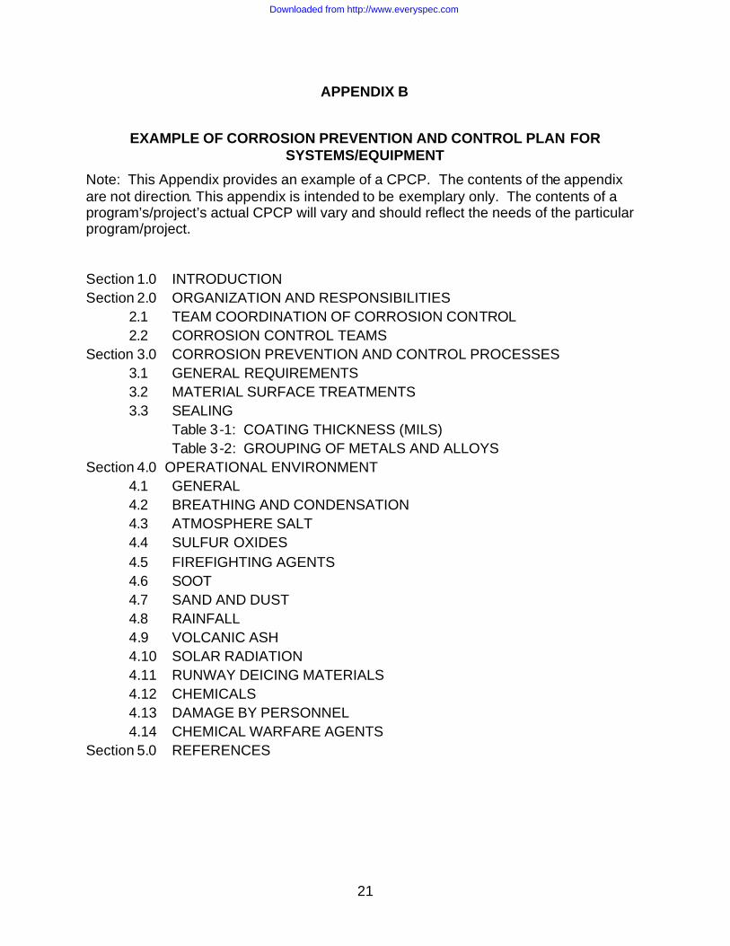
Note: This Appendix provides an example of a CPCP. The contents of the appendix are not direction. This appendix is intended to be exemplary only. The contents of a program’s/project’s actual CPCP will vary and should reflect the needs of the particular program/project. Section 1.0 INTRODUCTION Section 2.0 ORGANIZATION AND RESPONSIBILITIES 2.1 TEAM COORDINATION OF CORROSION CONTROL 2.2 CORROSION CONTROL TEAMS Section 3.0 CORROSION PREVENTION AND CONTROL PROCESSES 3.1 GENERAL REQUIREMENTS 3.2 MATERIAL SURFACE TREATMENTS 3.3 SEALING Table 3-1: COATING THICKNESS (MILS) Table 3-2: GROUPING OF METALS AND ALLOYS Section 4.0 OPERATIONAL ENVIRONMENT 4.1 GENERAL 4.2 BREATHING AND CONDENSATION 4.3 ATMOSPHERE SALT 4.4 SULFUR OXIDES 4.5 FIREFIGHTING AGENTS 4.6 SOOT 4.7 SAND AND DUST 4.8 RAINFALL 4.9 VOLCANIC ASH 4.10 SOLAR RADIATION 4.11 RUNWAY DEICING MATERIALS 4.12 CHEMICALS 4.13 DAMAGE BY PERSONNEL 4.14 CHEMICAL WARFARE AGENTS Section 5.0 REFERENCES
Downloaded from http://www.everyspec.com

22
SECTION 1: INTRODUCTION The purpose of the Corrosion Prevention and Control Plan is to describe the corrosion control tasks and responsibilities for the <system and support equipment>. Corrosion prevention and control (CPC) is defined as the rigorous application of engineering design and analysis, quality assurance (QA), nondestructive inspection (NDI), manufacturing, operations and support technologies to prevent the initiation of corrosion, avoid functional impairment due to corrosion, and define processes for the tracking and repair of corrosion problems. Corrosion prevention and control requires the coordinated efforts of numerous disciplines and organizations across the contractor teams and the Government Program Office. A Contractor Corrosion Team (CCT) will be established at each team company to oversee the Corrosion Control System and to provide a forum for the coordination of the CPC tasks assigned to each organization. Suppliers/vendors who have been granted design authority will actively participate in the CPC process by formulating their own CPC plans that meet the intent of this document and by participating in CCT meetings on an as-required basis. Team uniformity and coordination of CPC will be assured by a corrosion control group consisting of the chair of each CCT. The CCT will follow the Integrated Product Team (IPT) philosophy by ensuring that all decisions are properly coordinated and implemented with the full knowledge of the appropriate design IPT. Section 2 of this Corrosion Prevention and Control Plan (CPCP) defines the CCT, and assigns each corrosion control task to the responsible organization or discipline. The flow of these tasks is illustrated in Figure 1.1. Section 3 details specific CPC practices to be implemented through the Process/Finish Specification or Engineering Dataset. Section 4 provides background information and general design information for the interrelation of corrosion with the operating environments.
Downloaded from http://www.everyspec.com

23
Figure 1.1: Flow of Corrosion Prevention and Control Tasks
Downloaded from http://www.everyspec.com

24
SECTION 2: ORGANIZATION AND RESPONSIBILITIES This section defines the team organization to establish and implement the corrosion prevention and control system, and assigns task responsibilities. 2.1 Team Coordination of Corrosion Control A Contractor Corrosion Team (CCT) will be formed consisting of at least one Program representative from each of the team companies, chaired by the company IPT Corrosion Control Specialist. This team will provide and coordinate a consistent Corrosion Prevention and Control (CPC) policy. The responsibilities of this team are the following:
• Develop, document, and maintain the Corrosion Prevention and Control Plan. • Establish regular meetings and call special meetings if required. • Coordinate and document material selection guidelines for corrosion
protection/avoidance • Coordinate the documentation of corrosion design guidelines. • Coordinate Corrosion Prevention policies and procedures with other Team
policies and practices. • Review corrosion test results for process/finish material qualifications • Establish corrosion test requirements for procured items in conjunction with the
cognizant IPTs • Establish and maintain team-common process/finish requirements • Establish criteria for identification of corrosion specialists within IPTs • Resolve any impasse in determining the preferred process/treatment method for
corrosion control at any team site • Maintain a log of problems, action items, corrective actions, and status of each
for all sites • Coordinate and interface with government program office on the above
The CCT will meet as needed to resolve Team corrosion control issues and to assure coordination of the CCT and their activities. Meetings, whether formal, informal, electronic, or in person, will be documented by minutes distributed to all Corrosion Team members. The lead company CCT chairman will be the primary contact with government personnel on matters relating to corrosion control. All CCT members will participate in Corrosion Prevention Advisory Team (CPAT) meetings. CCT members will support CPAT and CCT meetings on an as required basis. 2.2 Contractor Corrosion Teams (CCT) A CCT will be established at each of the team companies that have design responsibilities to provide coordination among the organizations and technical disciplines responsible for or involved in corrosion control tasks. Each company will have a team chairman to manage the respective corrosion control team and to represent the company on the CCT. The CCT chairman will be a member of the applicable IPTs and an expert in the area of corrosion. Each CCT will provide a forum, through the representatives of the affected disciplines, to establish engineering,
Downloaded from http://www.everyspec.com

25
manufacturing, and quality requirements that will be implemented by the responsible organizations at that company consistent with CCT direction. The Teams are responsible to support the writing of the Corrosion Prevention and Control Plan (CPCP) and thereby to establish requirements for the generation of design guidelines, material specifications, process specifications, and quality control guidelines. Each CCT will consist of knowledgeable personnel representing, at a minimum, the following disciplines necessary to implement this corrosion prevention and control plan:
• Materials and Processes • Design • Reliability, Maintainability, and Supportability • Production Operations • Quality Assurance • Manufacturing • Hazardous Materials • Affected IPTs
2.2.1 Contractor Corrosion Team Responsibilities The CCT will guide, direct, and instruct the contractor(s) on corrosion prevention and control measures and verify that all measures implemented on the program are necessary, adequate, timely, and cost effective. The CCT principal responsibilities are as follows:
a. Review internal controls to ensure that corrosion prevention and control
techniques are established, implemented, and maintained. b. Review procedures for interim protection during all phases of manufacture and
during preparation for storage/packaging for shipment. c. Review training programs to ensure that the required corrosion prevention and
control techniques (i.e. finishing, sealing, and drainage systems, etc.) are properly addressed.
d. Provide technical input to corrosion control and other related technical
publications and review/approve the documents. e. Review and recommend approval of cleaning materials, solutions, and chemicals
not covered by approved specifications for use on the system, parts, and components.
f. Conduct failure analyses and provide corrective action for corrosion problems.
These analyses will be conducted and documented by the appropriate Failure Analysis Group, reported to the Material Review Board, and recorded in the corresponding corrosion control engineer’s log. A summary of this log from each Team Leader will be given to the CCT chairperson.
Downloaded from http://www.everyspec.com

26
g. Conduct quarterly CCT meetings to ensure implementation of this plan and to coordinate solutions for problems which arise during the development, design, and manufacturing phases. Additional CCT meetings will be conducted as required. Close communication of the CCT chairperson, company team leaders, and CPAT chairperson is to be maintained.
h. Maintain a log of problems and solutions/actions covered in Item 2.1.2f. i. Ensure that periodic reviews are made at all facilities to evaluate the adequacy of
corrosion prevention and control measures. j. Make field site inspections of systems when requested by the CPAT or on a
schedule as established by the CPAT. k. Incorporate environmental resistance requirements and verification methods into
the testing and selection of materials. Environment is defined as natural and man-made or operational environments. Materials include metallic and non-metallic materials.
l. Incorporate corrosion prevention and control measures into avionics, electro-
magnetic environmental effects, low observable technology, biological/chemical vulnerability and other related technologies.
m. Monitor and investigate industrial developments for processing and/or
process/finish improvements related to corrosion prevention and for cost effectiveness or compliance with environmental regulations.
n. Notify the CCT Chairperson of each CCT meeting date, meeting topics, and any
decisions resulting from the previous CCT meeting. o. Ensure that a balance is maintained between electrical bonding/grounding needs
and corrosion control approaches.
2.2.2 Corrosion Control Team Functional Tasks
The CCT is responsible for assuring that the following functional tasks are accomplished in accordance with this plan.
2.2.2.1 Materials and Processes
a. Write and maintain a Process/Finish Specification for the engineering and manufacturing development and production models to ensure compliance with the JMS.
b. Serve as design consultants for the selection of materials, processes, and
finishes.
Downloaded from http://www.everyspec.com

27
c. Review and approve Engineering drawings, system, and component specifications, and technical order manuals related to corrosion prevention and control.
d. Assist in disposition of parts whose surface finish is damaged or defective.
e. Initiate changes to material and process specifications and design as
required.
f. Assist Procurement in the evaluation of subcontractor capabilities.
g. Assist Procurement in the review of subcontractor specifications which may be used in lieu of those previously approved for the system, subject to final approval by the procuring activity.
h. Submit logs of corrosion problems and solutions/actions to the CCT
Chairperson
i. Maintain records of all inputs from the CCT.
j. Resolve disagreements by the CCT with actions taken by the CCT during the SDD and production phases.
k. Monitor developments in processing and/or finish requirements relative to
corrosion prevention for design incorporation.
l. Provide shop/manufacturing surveillance and support to assure compliance with specification requirements.
m. Provide Engineering Material Review Board participation and/or
assistance, as applicable, for materials and processes technical disciplines
2.2.2.2 Design
a. Recognize CCT decisions and incorporate these decisions into the product designs
b. Coordinate corrosion related design problems with the CCT.
Downloaded from http://www.everyspec.com

28
2.2.2.3 Reliability, Maintainability, and Supportability
a. Review drawings for conformance to standard corrosion prevention design practices.
b. Ensure the incorporation of RM&S considerations for materials and
finishes selection and development
c. Ensure corrosion related supportability design-to-requirements are current and available to the designers. This includes design reviews to ensure that hidden and/or inaccessible areas on the airplane are minimized.
d. Participate in design trade studies during all phases of design
development. Provide guidance on corrosion prevention based on experience from other aircraft programs,
e. Develop and recommend corrective and preventive procedures based on
Reliability and Maintainability analyses of field data on similar in-service equipment.
f. Document maintenance procedures and applicable logistics resources.
2.2.2.4 Production Operations
a. Review and analyze corrosion-related problems in all departments. Consultations with M&P corrosion engineers will be conducted as required during this process.
b. Request changes to engineering documentation to correct finishing
procedures or implement new procedures. 2.2.2.5 Quality Assurance
The CCT Quality Assurance authority consists of Process Control and Quality Control items as described below.
2.2.2.5.1 Process Control
a. Audit incorporation of engineering specification and/or design changes.
b. Perform tests on processing solutions and chemicals to monitor compliance of process parameters with applicable Engineering and/or Government specifications.
c. Maintain records of scheduled processing solution tests and prepare test
reports on specification compliance.
d. Initiate corrective action for nonconforming processes.
Downloaded from http://www.everyspec.com

29
e. Assist Procurement in evaluating processing capabilities of subcontractors upon request for such assistance.
f. Perform initial and subsequent subcontractor audits, as required, to verify
capability in applying the finish systems specified. 2.2.2.5.2 Quality Control
a. Verify that parts and assemblies are properly protected from corrosion during manufacture, while in stock, and when packaged for shipment.
b. Verify that parts are processed in accordance with the applicable
specifications/standards.
c. Verify that applied finishes conform to design and specification/standard requirements.
d. Reject any material or part that has been damaged or has not been
finished as required by applicable specification/standards. 2.2.2.6 Manufacturing (Planning)
a. Translate processing and finishing requirements of Engineering data on to planning documentation.
b. Provide planning requirements to ensure in-process corrosion protection
of the material or parts during manufacture.
c. Revise planning documentation when changes to Engineering design or specification requirements occur.
2.2.2.7 Hazardous Materials
a. Ensure that materials and processes comply with all federal and state regulations attempting to do so without compromising corrosion resistance.
b. Serve as focal point for coordination and distribution of new regulations
with the CCT, including new regulations regarding materials and processes.
SECTION 3: CORROSION PREVENTION AND CONTROL PROCESSES 3.1 General Requirements 3.1.1 The primary engineering document used to implement the CPCP is the
process/finish specification which should be incorporated into the released
Downloaded from http://www.everyspec.com
30
engineering dataset. The specification contains detailed finish instructions and guidelines which are incorporated by Design into engineering datasets and drawings. Materials and Processes will verify that these instructions and guidelines have been included in the datasets via the approval and sign off processes. The finish codes specify the material and process specifications which are used by Procurement to order material and by Manufacturing (Planning) to incorporate into the Manufacturing Operation sheets. For vendor designed parts and equipment, the vendor may elect to finish per the process/finish specification or may provide, through the CCT, alternate finish materials for approval by the CCT and cognizant IPT. All finishing materials should be used in conformance with Federal and State regulations.
3.1.2 Material Limitations 3.1.2.1 Aluminum Alloys - Mill product forms of aluminum alloys 2020, 7079, and
7178 should not be used for structural applications. The use of 7XXX-T6 aluminum alloys should be limited to thicknesses not to exceed 0.250 inches.
3.1.2.2 Corrosion Resistant Steel Alloys - Precipitation hardening steels should be
aged at temperatures not lees than 1000°F. Exception is made for castings which may be aged at 935°F ± 15°F, for fasteners which may be used in the 950 condition, and for springs which have optimum properties in the CH 900 condition. Corrosion resistant maraging steels should not be used in sustained load applications. Corrosion resistant 19-9DL and 431 steels should not be used for any applications. Series 400 martensitic grade corrosion resistant steels should not be used in the 700°F to 1100°F tempered condition. Unstabilized austenitic may be used up to 700°F. Only stabilized austenitic steels (321 and 347) should be used above 698°F. All welded or brazed austenitic steel should be solution heat treated after welding; however, welded 321 and 347, 304L and 316L may be used without heat treatment.
3.1.2.3 Magnesium alloys - Magnesium alloys will not be used for structural applications. All proposed non structural applications for components or subsystems should be submitted to the procurement activity for approval prior to incorporation into the design.
3.2 Material Surface Treatments
3.2.1 Aluminum Alloys
Surface treatments for aluminum alloys.
(1) Bare 2000 series and 7000 series - Chromic acid anodize per MIL -A-8625 Type 1B or thin film sulfuric acid anodize per MIL -A-8625, Type I C.
NOTE: Sulfuric acid anodize per MIL-A-8625, Type II, Class 1 or 2 may be used as an alternate to chromic acid anodize except on fracture or maintenance critical parts or those parts sized by fatigue requirements. Use of any other anodize treatments requires approval.
(2) Inherently corrosion resistant alloys of the 1000, 3000, 5000 and 6000
Downloaded from http://www.everyspec.com

31
series and aluminum casting alloys - Chemical conversion coat per MIL -C-5541 Class 1A using materials conforming to MIL-C-81706. Where a low resistivity contact is necessary for electrical bonding purposes, MIL -C-5541 Class 3 may be used.
(3) Exterior surfaces of adhesive bonded assemblies and spot welded or lap welded assemblies should be chemical conversion coated per MIL-C-5541 Class 1A using materials conforming to MIL-C-81706. The exterior surfaces of adhesive bonded assemblies may be coated with an approved corrosion-inhibiting adhesive primer in lieu of the MIL-C-5541 chemical conversion coating.
3.2.2 Titanium Alloys Titanium alloys do not require finishes for the purpose of corrosion protection. However surfaces contacting titanium should be protected from galling and dissimilar metal corrosion. Contact surfaces constituting dissimilar metal joints should have both surfaces coated with two coats of primer. As an alternative both surfaces may have one coat of applied primer and then be assemble wet with that primer. Similar metal contact points with titanium should have one coat of primer applied each surface in the joint to protect against galling. Prior to application of primer to titanium, the surface should be conversion coated in accordance with AMS 2486. Application of primer should begin within 16 hours after the application of conversion coating. Titanium alloys should not be cadmium or silver plated. Cadmium plated tools, clamps, fixtures and jigs should not be used for fabrication or assembly of titanium components. 3.2.3 Non-corrosion Resistant Alloy Steels Non-corrosion resistant alloy steels should be protected from corrosion as follows: 3.2.3.1 Non-corrosion resistant steel alloys whose maximum ultimate tensile strength is 180,000 psi or less should be IVD aluminum coated in accordance with MIL-DTL-83488, Class 3, Type II followed by Glass Bead Peening or cadmium plated in accordance with AMS QQ-P-416, Class 2 , Type II. Cadmium plate is allowable if and only if no suitable alternate is acceptable and each use of cadmium plating will require Materials & Processes approval. 3.2.3.2 Non-corrosion resistant steel alloys with ultimate tensile strength ranging from 180,000 to 220,000 psi should be IVD aluminum coated in accordance with MIL -DTL-83488, Class 3, Type II, Aluminum Ion Vapor Deposition, followed by Glass Bead Peening. 3.2.3.3 Non-corrosion resistant steel alloys whose ultimate tensile strength range is 220,000 psi or greater should be cleaned and cadmium plated per AMS-C-8837, Type II, Class 2 Vacuum Cadmium Plating; or coated per MIL -DTL-83488, Class 3, Type II, Aluminum Ion Vapor Deposition, followed by Glass Bead Peening. Cadmium plate is allowable if and only if no suitable alternate is acceptable and each use of cadmium plating will require Materials & Processes approval.
Downloaded from http://www.everyspec.com

32
3.2.3.4 When a wear-resistant coating is required on non-corrosion resistant alloy steels the surface should be nickel plated in accordance with QQ-N-290, Class 2, minimum thickness 0.002 inches or electroless nickel plated in accordance with MIL-C-26074 Class 1 or 2, Grade C, minimum thickness 0.0015 inch. This treatment is limited to steel alloy heat treated to 240,000 psi maximum. 3.2.3.5 Exceptions to the above requirements will be made for individual parts based on function and location as necessary. 3.2.4 Corrosion Resistant Steel Alloys
Corrosion resistant steels should be passivated in accordance with QQ-P-35 (or by methods approved by materials & processes engineering) except as noted in 3.2.4.1 through 3.2.4.5.
3.2.4.1 Carburized or nitrided surfaces or surfaces to be carburized or nitrided should not be passivated.
3.2.4.2 Corrosion resistant steel castings should not be passivated, but should be cleaned in accordance with Mil-S-5002.
3.2.4.3 Silver soldered joints and spot welded assemblies should not be passivated.
3.2.4.4 Assemblies containing crevices, slip joints and bellows which might trap cleaning and/or passivation solution should not be passivated without specific written approval from Materials and Processes Engineering.
3.2.4.5 Rough forgings, forged bar, and rolled plate should be descaled or machined on all surfaces prior to passivation. Descaling should be in accordance with AMS QQ-P-35 or methods approved by Materials & Processes Engineering. If acid etching is used to descale, the part should be baked for 4 hours at 350°F, within 8 hours, following the cleaning.
3.2.5 Graphite Reinforced Composites Surfaces of graphite composites in contact with aluminum or other dissimilar materials should incorporate a glass ply in the contact area. For epoxy-based laminates, the glass barrier ply should extend a minimum of 1 inch beyond the contact region. For condensation polyimide based laminates (e.g., bismaleimide, cyanate ester), the glass barrier ply should fully cover the laminate surface(s) in contact. In addition, a minimum of one coat of primer, or fuel tank coating should be used in the contact area. On assembly the joint between the composite surface and this dissimilar metal should be fay and fillet sealed sealant and fasteners wet installed using Mil-S-81733 or AMS 3276. Fasteners should be overcoated to the maximum extent practical using primer, fuel tank coating or sealant.
3.2.6 Other Coatings All structural materials exposed to fuel in fuel tanks will receive 1 coat of MIL -C-27725.
Downloaded from http://www.everyspec.com

33
Soft surface coatings such as nickel-cadmium, and aluminum should not be used for sliding or wear applications. Silver plated surfaces should not be used in applications where surface temperature exceeds 232°C (450°F). Cadmium should not be used without approval of the Hazardous Materials Team and review by the CCT. Cadmium plated fasteners should not be used. Protective systems to be used, specialty coatings for fuel tank interiors, rain erosion, crew compartment, anti-glare, etc., are defined in the engineering dataset and included in the process/finish specification. Refer to Tables 3-1 and 3-2 for guidance on these coatings. Dissimilar metals as defined in Table 3-3 are protected from galvanic corrosion in accordance with the requirements of the Process/Finish Specification.
Downloaded from http://www.everyspec.com
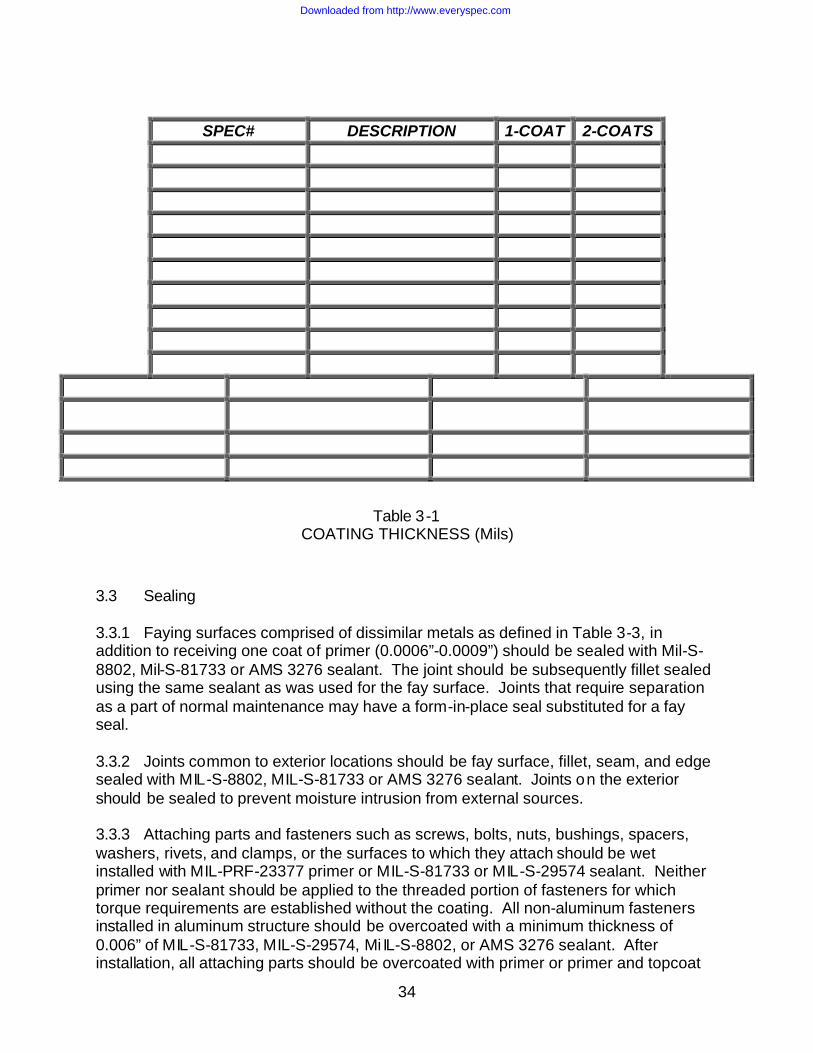
34
SPEC# DESCRIPTION 1-COAT 2-COATS
Table 3-1 COATING THICKNESS (Mils)
3.3 Sealing 3.3.1 Faying surfaces comprised of dissimilar metals as defined in Table 3-3, in addition to receiving one coat of primer (0.0006”-0.0009”) should be sealed with Mil-S-8802, Mil-S-81733 or AMS 3276 sealant. The joint should be subsequently fillet sealed using the same sealant as was used for the fay surface. Joints that require separation as a part of normal maintenance may have a form-in-place seal substituted for a fay seal. 3.3.2 Joints common to exterior locations should be fay surface, fillet, seam, and edge sealed with MIL-S-8802, MIL-S-81733 or AMS 3276 sealant. Joints on the exterior should be sealed to prevent moisture intrusion from external sources. 3.3.3 Attaching parts and fasteners such as screws, bolts, nuts, bushings, spacers, washers, rivets, and clamps, or the surfaces to which they attach should be wet installed with MIL-PRF-23377 primer or MIL-S-81733 or MIL-S-29574 sealant. Neither primer nor sealant should be applied to the threaded portion of fasteners for which torque requirements are established without the coating. All non-aluminum fasteners installed in aluminum structure should be overcoated with a minimum thickness of 0.006” of MIL-S-81733, MIL-S-29574, Mi IL-S-8802, or AMS 3276 sealant. After installation, all attaching parts should be overcoated with primer or primer and topcoat
Downloaded from http://www.everyspec.com

35
corresponding to the finish requirements of the surrounding area. Topcoat should match the color of the adjacent topcoat. Nuts and heads of bolts that are subsequently lubricated need not receive final finishing. 3.3.4 The exterior of electrical bond connections should be touched up to restore the finish in the surrounding area and subsequently sealed over with MIL-S-81733, MIL-S-8802, MIL-S29574, or AMS3276 sealant.
Downloaded from http://www.everyspec.com

36
GROUP I
Magnesium and its alloys (use requires approval), Aluminum alloy 5052, 5056, A356 (and other casting alloys), 6061 6013, and 6063 (and other 6000 series alloys)
GROUP II
Cadmium, zinc (use requires approval) 2000,7000 Aluminum alloys
GROUP III
Iron, Lead, and Tin and their alloys (except corrosion-resistant steel)
GROUP IV
Copper, Chromium, Nickel, Silver, Gold, Platinum, Titanium, Cobalt, and Rhodium and their alloys; Brass, corrosion-resistant steel, and Graphite
1. Metals classified in the same groups are considered as similar metals. 2. Materials classified in different groups are considered as dissimilar metals.
Table 3-2: GROUPING OF METALS AND ALLOYS
SECTION 4.0: OPERATIONAL ENVIRONMENT 4.1 General This section is presented as background information only. The operational environment is defined in the Environmental Criteria Document. Corrosion is defined as the environmental deterioration of any material, metallic, or non-metallic, and includes the environmental degradation of all materials. Ordinarily, corrosion is associated with metallic materials which are in the process of reverting to their natural states (oxides, carbonate, etc). Some metals and metalloids (graphite for example) are not corrosion prone but they will cause and accelerate corrosion on less noble metals in contact with them. For this reason, all vulnerable and metallic materials used on the system should be protected from the environment by the selection and use of the proper metallic materials; application of finish systems; faying surface sealing and wet installation of fasteners; and eliminating moisture traps or providing adequate ventilation. Designers should not depend upon interior equipment and interior surfaces to be adequately protected by sealing systems alone since it has been shown that, frequently, during paint stripping the sealant is also removed. More detailed information concerning solar radiation, humidity/rainfall, and icing temperatures may be found in the team Environmental Criteria Document. 4.2 Breathing and Condensation Breathing will occur in enclosures when a cyclic flow of air will go in and out of the enclosure primarily due to pressure changes during altitude variations and/or temperature fluctuations. In temperate and tropical zones, breathing will occur during
Downloaded from http://www.everyspec.com

37
daily temperature changes in the morning and evening hours when the outside air heats or cools, or when an airplane descends to warmer lower altitudes. For example, generally, the temperature will drop 3.5°F (1.95°C) per 1000 feet of ascent; therefore, at 85°F (29.4°C) at seal level, the temperature will be minus 20°F (-28.9°C) at 30,000 feet. The critical amount of moisture for corrosion initiation is 0.01 grams per square meter on unprotected metallic surfaces. By comparison, the amount of moisture on a metal surface in an outdoor atmosphere is 1.0 g/m2 when wet with rain. Depending upon design areas, breathing will vary; however, breathing most likely will occur in enclosed areas open to the outside through unsealed joints in unpressurized areas and in instruments and electronic equipment boxes. 4.3 Atmosphere Salt Normal sea breezes can carry from 10 to 100 pounds of salt per cubic mile of air. Although the salt-laden air may travel inland on sea breezes for a distance of up to 12 miles, the major amount of salt fallout occurs within the first one-half mile of the beach. Beyond about 10 miles inland, the fallout is insignificant. In the northern, cooler latitudes, the salt content of air is much less of a problem than in temperate and equatorial regions. Salt is also much more concentrated in air at lower altitudes than at higher altitudes. The heaviest concentrations are below 3000 feet over the water in areas of trade winds. Also, systems at bases on the sea coast in temperate areas are sometimes subject to fallout of corrosive iodine produced by masses of kelp floating along the coastline. 4.4 Sulfur Oxides Sulfur oxides are normally associated with industrial and large urban areas. In the past, sulfur-containing fuels, such as coal, produced enormous quantities of byproducts. Automobiles and volcanoes also emitted some of these same contaminants. Within the last ten or so years, there has been considerable reduction in emission output due to federal and state laws which require smoke stack scrubbers, catalytic converts, etc. Even through there have been reductions in sulfur oxides, the levels are still high enough that when mixed with moisture a strong sulfurous acid, principally sulfuric acid, is formed (acid rain) which can cause corrosion and also attack other materials, particularly rubber products which are the most vulnerable. 4.5 Firefighting Agents Some fire fighting agents used to extinguish fires pose no risk at all to metallic structure; however, many fire-extinguishing agents are corrosive and can very quickly produce severe corrosion. Foam and bromochloromethane and, to a slightly less degree, dibromochloromethane type agents are the most notable offenders in this regard. Some of the more commonly used dry powder agents, such as potassium bicarbonate (PKP) are in themselves only mildly corrosive, but after exposure to heat, the residue may convert to potassium hydroxide, a product which is very corrosive to aluminum. Both of these potassium salts are hygroscopic and will absorb moisture, creating a corrosive deposit on airplane surfaces.
Downloaded from http://www.everyspec.com
38
4.6 Soot Soot, generated by a fire or from normal engine operation is carbon, including a variety of combustion byproducts and sulfur oxides, depending on what has been burned. Soot is both corrosive and hygroscopic. It imbeds itself into painted surfaces and is very difficult to clean off. Severe corrosion will result where paint has been chipped on aluminum structure because of the small anode (aluminum) and very large cathode (soot) being in contact with each other in the presence of moisture. 4.7 Sand and Dust Blowing sand and dust can cause erosion of leading edges and settle into all accessible areas of the airplane. Impeding the function of oil and air filters and contaminate electrical and avionic equipment. When damp, a poultice is formed against the structure, resulting in corrosion. Furthermore, even though the climate may other wise be acceptable in some desert regions, many deserts are the sites of ancient sea beds and the sand often contains a significant amount of salt. 4.8 Rainfall Rainfall provides some benefit in corrosion prevention by washing away some contaminants. During periods of high acid rain activity, the beneficial effect of rain will be somewhat diminished. In either case, improperly sealed joints, open cavities, and trap areas will allow corrosion initiation within these areas. 4.9 Volcanic Ash The ash contains corrosive substances such as sulfur compounds, fluoride, and chloride salts, and strong inorganic acids. These chemical are often carried on the surface of ash particles, which are highly abrasive bits of pulverized rock and can cause erosion of leading edges and internal engine parts. Particle sizes usually range from 05. Microns to 100 microns and, since most airplane filters will remove material down to 15 microns, smaller material could impede air and fluid filters. The ash will most likely be encountered as a fine powder, similar to talcum powder and will be light gray in color. In the presence of moisture, the ash becomes a corrosive paste that tends to set up somewhat like concrete. Airplanes that may have accumulated this material during flight, or on the ground, may need special cleaning, both inside and out. Even when ash is not visible, airplanes that operate within the vicinity of volcanic activity can be contaminated with corrosive acids. Exposure to the acids can be checked with nitrizine paper. A pH of four (4) or below is an indication that cleaning is required. 4.10 Solar Radiation Although solar radiation (sunlight) is not corrosive, it will cause chalking of paint; it will cause hydrolysis of chlorinated organics; and it will degrade exposed plastics and elastomers. Degradation of these materials will allow an electrolyte, usually in the form
Downloaded from http://www.everyspec.com

39
of moisture and its corrosive constituents, free access to the underlying metallic surfaces. 4.11 Runway Deicing Materials There are several types of runway deicers. The glycol-based material is not considered to be a corrosion problem. Urea type deicers are the most commonly used. Calcium magnesium acetate can, when ingested into the engine or APU in conjunction with sea salt, initiate corrosion on turbine parts. Potassium acetate and sodium formate by their chemical nature have the potential, if ingested by the engine core, to cause hot corrosion on turbine parts. The level of hot corrosion, however, would probably be no worse than hot corrosion caused by airborne salt. Runway deicing salts can also cause chemical attack, especially in low areas. There materials should not be allowed to puddle, and joints and crevices should be sealed to prevent entry. 4.12 Chemicals Maintenance chemicals, such as cleaners, acids, paint strippers, solvents, etc., can present as many different problems as there are chemicals being used. Paint strippers, solvents, and some cleaning agents can, when improperly used, deteriorate paint, plastics and elastomers. Some paint strippers, some cleaners, and most acids are very corrosive to airplane structure. Designers should select materials or impose preventive measures to prevent or lessen damage from chemical attack. Additionally, maintenance personnel should be thoroughly familiar with the chemicals they use while performing maintenance on the airplane. 4.13 Damage by Personnel Maintenance personnel can greatly contribute to corrosion on the system. Walking on surfaces and dropped tools and equipment will sufficiently damage the paint to allow corrosion initiation in addition to possible structural damage. Removal of cast in place and mechanical seals and sealant, without proper reinstallation, will allow moisture to enter internal areas of the system. 4.14 Chemical Warfare Agents During periods of war, the system may be required to operate and be maintained in an environment of chemical agents. All removable equipment, unsealed compartments, etc. are susceptible to contamination. The system should be able to survive in the chemical threat environment and be capable of decontamination after exposure. Contaminants and the decontamination process should not cause corrosion of the exposed structure and equipment.
Downloaded from http://www.everyspec.com

40
SECTION 5: REFERENCES [1] Joint Services Specification Guide.
[2] “System Environmental Criteria Document”
[3] "Process/Finish Specification”
[4] MIL-A-8625: Anodic Coatings for Aluminum and Aluminum Alloys
[5] MIL-C-5541: Chemical Conversion Coatings on Aluminum and Aluminum Alloys
[6] AMS 2486: Conversion Coatings of Titanium Alloys
Downloaded from http://www.everyspec.com

41
APPENDIX C
EXAMPLE OF CORROSION PREVENTION AND CONTROL PLAN FOR FACILITIES Note: This Appendix provides an example of a CPCP. The contents of the appendix are not direction. This appendix is intended to be exemplary only. The contents of a program’s/project’s actual CPCP will vary and should reflect the needs of the particular program/project. 1.0 Objectives. The primary goals of the corrosion control planning are to develop and maintain dependable and long-lived structures, equipment, plants, and systems; conserve energy; reduce costs due to corrosion, scale, and microbiological fouling; and ensure compliance with Environmental Protection Agency, Department of Transportation, Occupational Safety and Health Administration, and other applicable regulations and guidance.
Downloaded from http://www.everyspec.com

42
2.0 Scope. Corrosion control keeps the effects of electrochemical or chemical attack on materials by the environment to a minimum. The planning includes: 2.1 Establishing a Corrosion Prevention Advisory Team (CPAT) 2.2 Establishing a Contractor Corrosion Team (CCT) 2.3 Corrosion control by design and materials selection. 2.4 Use of cathodic protection to eliminate electrochemical reactions (corrosion). 2.5 Use of industrial water treatment to reduce corrosion, scale -forming deposits, and biological growths in heating and cooling systems. 2.6 Use of protective coatings to reduce atmospheric corrosion or cathodic protection current requirements. 2.7 Analysis of logs and records for failure prediction and selection of corrective actions. 2.8 Incorporation of corrective actions in repair and construction projects when corrosion, scale, or material deterioration occur due to materials, design, construction, operation, or the environment.
Downloaded from http://www.everyspec.com

43
3.0 Responsibilities. 3.1 Headquarters Air Force Civil Engineer Support Agency. The Air Force Civil Engineer Support Agency (AFCESA) oversees the Air Force’s facility corrosion control planning in the Technical Support Directorate, Mechanical/Electrical Engineering Division (HQ AFCESA/CESM). The agency: 3.1.1 Assists HQ USAF (HQ USAF/ILE) in formulating corrosion control policy. 3.1.2 Maintains Air Force corrosion control technical publications and coordination on tri-service technical publications. Develops technical standards, criteria, and procedures with Department of Defense staff elements and other Federal agencies. 3.1.3 Provides specialized field assistance and consultation to Air Staff and major commands on special corrosion control problems, including designs, construction acceptance, and failure analysis. 3.1.4 Provides corrosion literature searches and deliver any publicly available, but difficult to find, engineering document. Through agreement between HQ AFCESA and the Air Force Research Laboratory, Airbase and Environmental Technology Division (AFRL/MLQ), contact the Technical Information Center as follows for literature or documents:
Technical Information Center AFRL/MLQ-TIC (FL 7050) 139 Barnes Drive, Ste 2 Tyndall AFB FL 32403-5323 Defense Switching Network (DSN) 523-6285 FAX: (904) 283-6286 FAX: DSN 523-6286
3.1.5 Approves corrosion control methods and equipment not specified in Air Force publications. 3.1.6 Maintains a list of all corrosion points of contacts at the major command level to include full name, complete mailing address, DSN and commercial telephone and fax numbers, training received, and assigned corrosion duties. 3.1.7 Compiles each fiscal year a summary of funded projects justified all or in part by corrosion control and a summary of leak records. Catalogs and analyzes these data for trends. 3.2 Major Commands. Major command civil engineers assist bases in developing and executing corrosion control planning (including aqueous, atmospheric, and underground corrosion) to ensure compliance with Department of Defense and Air Force policy; Environmental Protection Agency, Department of Transportation, and Occupational Safety and Health Administration regulations; and local (including host country) requirements. Major command civil engineers or designated representatives:
Downloaded from http://www.everyspec.com

44
3.2.1 Assign the office of primary responsibility for the planning. Appoint command corrosion engineers to act as the overall focal point in all corrosion control related matters. Appoint staff engineers as required to work with the command corrosion engineers as technical consultants in the three major areas of corrosion control: cathodic protection, industrial water treatment, and protective coatings. 3.2.2. Provide ins tallations with technical assistance and guidance on corrosion control. Develop a major command training policy for corrosion control to support budget requests. Past experience indicates that some type of annual contact with others involved in corrosion control maintains interest, allows networking on day-to-day problems, and cross-feeds new approaches and solutions. This is significant as most corrosion control positions are one-deep. 3.2.3 Regard corrosion control as a functional design requirement of all facilities exposed to the environment. Ensure data and justifications are part of each project. This applies to all phases, from planning, project definition, and programming through design and construction to final acceptance. Programming documents should include environmental and safety factors and associated costs. Ensure key corrosion control features of projects have separate design documentation, including drawings, specifications, and design analyses. 3.2.4 Ensure accomplishment of designs, design reviews, and construction inspection by qualified individuals according to major command policy for Military Construction Program and Operations and Maintenance projects. Past experience indicates design qualifications should include recognition by professional organizations, such as NACE International or state registration authorities, or 5 years’ experience in design and maintenance of the corrosion control measures under review. Consult HQ AFCESA for review support when necessary. 3.3 Corrosion Prevention Advisory Team (CPAT) will: 3.3.1 Ensure design according to publications referenced in attachment 1. 3.3.1.1 Accomplish surveys and design before construction contract advertisement or before construction in design-build contracts. 3.3.1.2 For design of corrosion control measures, ensure designer or design reviewer meets qualifications according to major command policy. For example, an experienced NACE International Accredited Corrosion Specialist, NACE International Certified Cathodic Protection Specialist, or a Registered Professional Corrosion Engineer accredited or registered in cathodic protection should perform contracted cathodic protection surveys and designs. 3.3.2 Not delete corrosion control measures from any design without the specific approval of the command corrosion engineer. 3.3.3 Coordinate with the command corrosion engineer and the base corrosion control engineer during preliminary design. This coordination will ensure compatibility of design
Downloaded from http://www.everyspec.com

45
with existing corrosion control systems and maintenance of successful techniques within craftspersons’ capability. Installation personnel will approve the updating of systems and equipment per designer’s recommendations. 3.3.4 Perform failure analysis for replacement projects that did not achieve life expectancy. Ensure complete understanding of the failure and include procedures in the specifications to prevent recurrence. This analysis shall be part of the preliminary design submittals. 3.3.5 Coordinate among design team members to ensure material selections and system designs are compatible with the corrosion control approach selected. 3.3.6 Not allow the construction contractor to continue with any work until approval of the corrosion control system shop drawings. The technical reviewer, usually the contracting officer’s technical representative, shall be knowledgeable in the installation of the corrosion control systems. 3.3.7 Ensure the contractor notifies the contracting officer a minimum of 24 hours prior to installation, testing, o r final acceptance of corrosion control systems. 3.3.8 Ensure the construction inspector understands the corrosion control system installation or will involve the base corrosion control engineer or craftsperson as technical advisor. This involvement includes construction surveillance during installation, testing, and final acceptance. If the construction agent cannot ensure the presence of an in-house inspector during cathodic protection work, the construction agent will use Title II Construction Inspection Services to obtain a full-time qualified inspector. 3.3.9 Ensure the specifications contain acceptance testing to ensure achievement of design criteria and the contractor performs this acceptance testing with installation representatives in attendance. 3.3.10 As-built drawings shall provide the location of corrosion control system equipment, testing points, sampling points, and items requiring periodic maintenance. 3.3.11 Use field surveys, field tests, and experience of installation personnel in the design. 3.3.12 Specify the testing necessary for the final acceptance of the corrosion control system. Target values of system operating parameters will be part of this testing to ensure the facility will function within design limits. Ensure the acceptance testing protocol includes procedures if acceptance testing differs from target values. Consult operations personnel, equipment manufacturers, and the construction contractor to determine solutions and set new equipment operating points. 3.3.13 Incorporate operability and maintainability into the overall design of the corrosion control systems. Designs will provide minimum life cycle cost over the facility life expectancy.
Downloaded from http://www.everyspec.com

46
3.3.14 Provide detailed calculations and one-line diagrams at the preliminary design stage to show the magnitude and layout of the corrosion control system. For example, validate the use of pre-engineered tanks with factory installed cathodic protection through appropriate calculations and field tests. 3.3.15 Provide corrosion control system drawings to show location of equipment, test points, sampling points, potential cathodic protection interference, items requiring periodic maintenance, and installation details. 3.3.16 Ensure appropriately qualified and trained personnel develop and execute a comprehensive corrosion control planning, encompassing the three areas of corrosion control. Ensure compliance with applicable Federal, state, local, and host nation laws and regulations, particularly those related to public safety and environmental protection. The planning will include applying and maintaining effective corrosion control methods in design, operations and maintenance, quality assurance, and acceptance testing. 3.3.17 Publish a squadron operating instruction for the corrosion control planning. Ensure civil engineer squadron craftspersons receive annual training on the requirements of the squadron operating instruction. 3.3.18 Develop and manage the base corrosion control planning. 3.3.19 Assist programmers in narrative and cost estimates for corrosion control line items on DD Forms 1391. 3.3.20 Participate in project design and design review related to corrosion control. Sign all project drawings when corrosion control measures, operability, and maintainability are adequate. 3.3.21 Provide technical advice to the construction inspector during installation, testing, and final acceptance of corrosion control systems. 3.3.22 Coordinate operations and maintenance of corrosion control systems with the operations flight, including preventive maintenance scheduling. Ensure control charts for industrial water treatment detail the frequency and actions for testing and adjustment of each system. 3.3.23 Review corrosion control records and take action to correct deficiencies. 3.3.24 Investigate leaks from corrosion, tuberculation, and scaling in heating and cooling systems, and premature failure of protective coatings. Take corrective action in each case, other than simple repair by replacement. 3.4 The Contractor Corrosion Team (CCT) will: 3.4.1 Assure that adequate corrosion prevention and control requirements are being implemented in accordance with the project contract, plans, and specifications.
Downloaded from http://www.everyspec.com

47
3.4.2 Assure that the implementation of corrosion prevention and control is documented and that documents are submitted in accordance with the required schedule. 3.4.3 Establish periodic meetings, as required, to resolve problems as they occur. Other meetings should be convened should a critical or major problem arise which requires action by the CCT or CPAT. 3.4.4 Notify all DoD and contractor members of each meeting date, the topics to be discussed, and any decisions resulting from the previous meeting. 3.4.5 The chairperson or his designees should sign off on all construction d rawings after review of materials selection, treatments, and coatings. 3.4.6 The chairperson will maintain a continuing record of all action items and their resolutions.
Downloaded from http://www.everyspec.com

48
4.0 Requirements: 4.1 Environmental. Consult AFPD 32-70, Environmental Quality, and associated Air Force Instructions (AFI) to understand the impact of corrosion and corrosion control activities on the environment. 4.1.1 The primary environmental impact of cathodic protection is in the prevention of petroleum, oil, and lubricants corrosion-induced leakage into the environment from underground and on-ground tanks and underground piping. Cathodic protection is already a requirement on new tank installations. The goal is to prevent all notices of violation due to corrosion. Ensure compliance with AFI 32-7044, Storage Tank Compliance; Title 40, Code of Federal Regulations, Part 280; and applicable state and local requirements. 4.1.2 The primary environmental concern of industrial water treatment is the proper disposal of chemically treated water. Consult AFI 32-1067, Water Systems. Also consult environmental engineering and bioenvironmental engineering prior to selecting any industrial water treatment chemical. 4.1.3 The following environmental laws apply to industrial water treatment. Consult with bioenvironmental engineering and environmental engineering to determine methods of compliance with laws and local practices. 4.1.3.1 Toxic Substances Control Act (15 U.S.C. 2601) authorizes the U.S. Environmental Protection Agency to control existing and new chemical substances determined to cause unreasonable risk to the public health or environment. 4.1.3.2 Clean Water Act (33 U.S.C. 1251) includes the Federal Water Pollution Control Act and amendments. This act establishes limits for the discharge of pollutants to navigable waters, regulations on specific toxic pollutants in wastewater discharges, and control of oil and hazardous substance discharges. 4.1.3.3 Safe Drinking Water Act (42 U.S.C. 300) provides for protection of underground sources of drinking water and establishes primary and secondary drinking water standards. 4.1.3.4 Federal Insecticide, Fungicide, and Rodenticide Act (7 U.S.C. 136-136y) requires the U.S. Environmental Protection Agency to register all pesticides. 4.1.3.5 Resource Conservation and Recovery Act (42 U.S.C. 690) addresses the control of solid and hazardous waste. The act defines hazardous waste and controls it by a complex manifest system designed to track a waste from its generation to final disposal. 4.1.3.6 Comprehensive Environmental Response, Compensation, and Liability Act (42 U.S.C. 9601), also commonly referred to as "Superfund," defines procedures for responding to existing uncontrolled hazardous waste sites, establishes the National
Downloaded from http://www.everyspec.com

49
Priorities List and the National Contingency Plan, and requires the reporting of hazardous substance releases into the air, land, and water. 4.1.3.7 Clean Air Act (42 U.S.C. 7401) regulates air emissions from stationary and mobile sources to protect public health and welfare. State and local governments have the primary responsibility to prevent and control air pollution. 4.1.4 Do not use chromates in any industrial water treatment application. 4.1.5 The environmental concerns of protective coatings center upon metal content in the dried paint and volatile organic compounds that evaporate from solvent-based paint. 4.1.5.1 Lead-containing paint has a lead content of more than 0.06 percent lead by weight (calculated as lead metal) in the total nonvolatile content of liquid paint or in the dried film of the paint already applied. Do not use lead-containing paint on any Air Force facility. Note that nonlead-containing paint must still pass a Toxicity Characteristic Leaching Potential Test or be considered hazardous waste during disposal. 4.1.5.2 The U.S. Environmental Protection Agency restricted the use of mercury-containing fungicides in solvent-thinned, oil-based paint. Exterior water-thinned paints may contain a maximum of 0.2 percent mercury (calculated as metal) in the total weight of the paint. Clear markings indicating the mercury content must be on the container. The U.S. Environmental Protection Agency banned the use of mercury in interior paint applications. 4.1.5.3 The U.S. Environmental Protection Agency identified six major pollutants that may harm the public health and welfare. Ozone is one of these pollutants. Since the presence of organic materials in the air directly relates to the ozone concentration in the air, volatile organic compounds used in the drying and curing of coatings have environmental impact. Volatile organic compound limits vary by region of the country and the end-use surface coating operation. 4.2 Safety. Consult AFPD 91-2, Safety Programs, and AFPD 91-3, Occupational Safety and Health, as well as their associated AFIs, for guidance to minimize the risk of corrosion and corrosion control activities on facility and worker safety. 4.2.1 For cathodic protection, consult AFI 32-1064, Electrical Safe Practices. The Department of Transportation regulates flammable utilities. The Natural Gas Pipeline Safety Act of 1968, as amended, and the Hazardous Liquid Pipeline Safety Act of 1979, as amended, provide the minimum criteria to ensure safe operation. 4.2.2 Many of the chemicals used to treat industrial water may be harmful to the health of the operator and other base personnel. They range from highly toxic to mildly irritating to the persons handling them. Handle water treatment and testing chemicals with care, following guidance in Occupational Safety and Health Administration directives, manufacturer’s recommendations, and the material safety data sheets. Install eye wash stations and safety showers according to ground safety requirements. Consult
Downloaded from http://www.everyspec.com

50
with wing safety, bioenvironmental engineering, and environmental engineering on potential safety issues and the use of less hazardous substitutes. 4.2.2.1 A cross-connection is a physical connection between a potable water supply system and a non-potable system (such as an industrial water system) through which contaminated water can enter the potable water system. Consult AFI 32-1066, Plumbing Systems. Permit only Class III backflow prevention devices (air gap or reduced pressure principle) to provide makeup from a potable water system to an industrial water treatment system. 4.2.2.2 Morpholine, cyclohexylamine, and similar chemicals added to protect condensate lines from corrosion make the steam and condensate unfit for consumption or other uses normally reserved for potable water. Do not use treated steam in direct contact with food or for any direct steam humidification, such as in a gymnasium steam room or humidity control for electronic equipment. 4.2.3 Most paint and protective coatings are hazardous to some degree. All except water-thinned paints are flammable; many are toxic; and others can irritate the skin. By following simple precautions, most paints are quite safe during application. Surface preparation also has intrinsic hazards. For example, sandblasting operations generate clouds of blasting media, paint, and substrate material. Dry sanding on lead-containing paint and on certain types of non-lead-containing paint can generate excessive amounts of airborne lead dust. The Occupational Safety and Health Administration controls the permissible exposure limit of these airborne particulates and the personal protective equipment required. Consult wing safety and bioenvironmental engineering for specific information. 4.3 Design 4.3.1 Design, construction, and application of cathodic protection, indus trial water treatment, and protective coatings are functional requirements for almost all projects. Designs shall achieve the minimum life cycle cost for the overall facility. Base personnel must be able to operate and maintain the final facility design, i ncluding the corrosion control systems, without extensive training or equipment investment, unless this is the best approach to achieve minimum life cycle cost. 4.3.2 Corrosion resistance is not the only criterion for material selection. When selecting a material, investigate all aspects of its physical properties in the application environment, during both normal operation and typical system failure. 4.3.3 Clearly and distinctly document corrosion experience for future reference. This experience should refer to design, material selection, selection of corrosion control technique, or decisions of no requirement for corrosion control. Document all design and selection decisions in project design analyses. Pass this information to the operations and maintenance elements to assist future decisions. 4.3.4 Revisit the design and selection decisions when a system malfunctions or leaks due to corrosion, scaling, or premature failure of the corrosion control system. This is
Downloaded from http://www.everyspec.com
51
especially important for the rare case when a designer justified no corrosion control being needed. 4.3.5 Ensure new or supplemental corrosion control systems are compatible with existing systems. The construction contractor shall not select the warranty period industrial water treatment. 4.3.6 Construct pipelines in a manner that facilitates use of in-line inspection tools. 4.3.7 Cathodic protection and coatings work together. Ensure these items are part of the design. Do not design submerged or buried coated metallic facilities without cathodic protection and do not design cathodic protection on bare metallic facilities. Recommend fiberglass-clad underground storage tanks be installed with galvanic anodes. This recommendation is made even though many such tanks are EPA-approved for installa tion without cathodic protection. 4.3.8 Do not use unbonded coatings, such as loose polyethylene wraps. Use of unbonded coatings is a direct violation of Department of Transportation regulations and Air Force criteria for pipelines. 4.3.9 Provide both cathodic protection and protective coatings for buried or submerged metallic facilities, regardless of soil or water corrosivity, when the facility:
• Carries flammable product • Is mission critical • Would be expensive to maintain • Would waste energy or impact the environment if corroded • Requires corrosion control as identified by major command
4.3.10 For other buried utilities, generally provide cathodic protection and protective coatings if the soil resistivity is below 10,000 ohm-centimeters. Follow the documented recommendations of a qualified corrosion engineer when the soil resistivity is above 10,000 ohm-centimeters. 4.3.11 Provide both cathodic protection and protective coatings for the following aboveground tanks based upon qualified analysis: 4.3.11.1 All ferrous tanks in contact with the earth, unless built on an oil-filled sand pad with plastic liner underneath. 4.3.11.2 Interiors of steel water distribution storage tanks. 4.3.12 Consider the need for lightning and fault current protection at isolating devices (dielectrically insulated unions and flanges) when designing cathodic protection systems. Consult AFI 32-1065, Grounding Systems. 4.3.13 Installed cathodic protection systems shall provide protective potentials meeting criteria in NACE International Standard RP0169, Control of External Corrosion on Underground or Submerged Metallic Piping Systems, Section 6, Criteria and Other
Downloaded from http://www.everyspec.com
52
Considerations for Cathodic Protection. Structure-to-soil potentials are to be potential drop (current times resistance) free. 4.3.14 Special conditions sometimes exist where cathodic protection is ineffective or only partially effective. Corrosion personnel may deviate from this instruction after documenting the achievement of objectives and receiving command corrosion engineer approval. 4.3.15 Industrial water treatment designs or decisions begin with an analysis of the system makeup water. Consult bioenvironmental engineering and AFI 48-119, Medical Service Environmental Quality Programs, for sampling potable water sources that feed industrial systems. Use AF Form 2752A, Environmental Sampling Data, for complete analyses to identify the quantity and relationship of water constituents for industrial water treatment purposes. 4.3.16 Acceptance testing of new heating and cooling systems will ensure the industrial water treatment system meets design and operation parameters. Boiler steam purity tests will determine total dissolved solids limits. Correlate the total dissolved solids level selected for boiler operation to the conductivity reading of a typical sample. The Water or Wastewater Laboratory at associated plants or Base Supply’s Fuels Laboratory usually can measure total dissolved solids using American Society for Testing and Materials standard methods. Verify the selected condensate treatment meets design parameters by testing for copper, iron, and pH at near, medium, and far points from the boiler throughout the system. 4.3.17 Indicate locations to install corrosion coupon racks following American Society For Testing and Materials Standard Test Methods for Corrosivity of Water in Absence of Heat Transfer (Weight Loss Methods), D26888-92, Test Method B. The coupons are the best confirmation of industrial water treatment effectiveness. 4.3.18 Do not use nonchemical industrial water treatment devices on Air Force systems either regularly or on a test evaluation basis except as indicated below. This includes the Management and Equipment Evaluation Program. 4.3.18.1 Basic research and application development of nonchemical industrial water treatment devices has been underway since before 1935. However, many variables affect performance, and no criteria and standards have been developed which may be incorporated into guide specifications or statements of work. Such criteria and standards are necessary for standard Air Force contracting methods to ensure devices will perform as advertised. Additionally, due to downsizing and outsourcing, the technical capability to perform installation-specific test evaluations is not available at installation level. 4.3.18.2 Battelle Memorial Institute is researching applications of nonchemical industrial water treatment under the Department of Energy’s Federal Energy Management Program. Various Energy Services Companies (ESCO) are investigating use of these devices for energy and water conservation measures under Energy Savings Performance Contracting (ESPC). Under ESPC, the ESCO provides guaranteed savings that are validated each year to reconcile payments, using an agreed-upon
Downloaded from http://www.everyspec.com

53
measurement and verification methodology. As the ESCO has the responsibility for measuring and verifying performance, problems cited in paragraph 4.3.18.1 are overcome. Currently, HQ AFCESA/CESM is developing measurement and verification standards to allow nonchemical devices to be available for use under ESPC. 4.3.19 Light reflective floor coatings include chemically resistant urethane for existing hangar floors and dry shake metallic floor topping applied to the top layer of freshly poured concrete for new floors. Ensure electrostatic discharge and slip resistance are part of the design. Include the daily cleaning requirements to cover equipment, supplies, and frequency as part of the maintenance instructions provided to the using agency. 4.3.20 Avoid using chemical strippers. If specified, perform effectiveness tests prior to award of any contract. This is especially necessary for removing lead-based paint from wood. Also, specify procedures to confirm neutralization of alkaline paint stripper through chemical testing. Alkaline residue left on the substrate is a recurring paint failure mechanism. 4.4 Maintenance 4.4.1 Perform routine maintenance checks, surveys, and inspections of cathodic protection, industrial water treatment, and protective coating systems. Each installation must have the basic equipment and training to perform tests and measurements of installed corrosion control systems. Consult associated manuals and tables of allowances for the minimum required field inspection instruments. 4.4.2 Investigate when corrosion control actions do not achieve results. This information provides the basis for selecting corrective actions and ensuring future projects do not continue the same problems. 4.4.3 Select and apply methods for determining voltage drops during cathodic protection testing using sound engineering practices, such as contained in NACE International Technical Report 10A190, Measurement Techniques Related to Criteria for Cathodic Protection of Underground or Submerged Steel Piping Systems (see attachment 1). 4.4.4 Cathodic protection situations involving stray currents and stray electrical gradients require special analysis. For additional information, see MIL-HDBK 1136, Maintenance and Operation of Cathodic Protection Systems, Section 7; and NACE International Standard RP0169, Section 9, Control of Interference Currents. 4.4.5 Industrial water treatment requires testing at a frequency that ensures the prevention of scale, corrosion, and biological formation in the heating and cooling systems. The time between testing depends on system integrity and operations. A mechanically sound system will require less frequent testing as less chemical leaves the system over time. 4.4.6 Develop and post, in appropriate locations, control charts for each boiler, cooling tower, and closed system showing the treatment chemicals used, the amount to add per operating parameter, the testing required, the limits to maintain in the system, what to
Downloaded from http://www.everyspec.com

54
do if the chemical levels are above or below the limits, and any other information peculiar to the system. 4.4.7 Perform periodic surveys to ensure effective industrial water treatment. 4.4.7.1 Annually check the capacity of ion exchangers. Do not rely on a timed regeneration cycle. 4.4.7.2 Once at the start of heating season and once at the end of heating season, test the condensate throughout the return system to identify potable water leakage into the condensate return system at heat exchangers. This identifies leaks at the earliest stages. 4.4.7.3 When adding or deleting buildings to a steam system or significantly changing industrial water treatment chemicals, perform the design acceptance tests for the boiler total dissolved solids limit and verify the total protection of the condensate return system.
Downloaded from http://www.everyspec.com

55
5.0 Recordkeeping. Corrosion control logs and reports are valuable in any failure analysis when problems arise. They provide the facts to make decisions. They also provide managers the status of the systems and the ability to make incremental improvements to achieve the expected life cycle of facilities, equipment, and piping. The goal is to solve the small problems at the operational level before they become so large that a major project is the only solution. 5.1 Cathodic protection recordkeeping, using prescribed forms as explained in MIL-HDBK 1136, includes the following: 5.1.1 Initial close interval, anode bed, and annual corrosion surveys of installed impressed current and sacrificial systems. Use AF Form 491, Cathodic Protection Operating Log for Impressed Current Systems; AF Form 1686, Cathodic Protection Operating Log for Sacrificial Anode System; and AF Form 1688, Annual Cathodic Protection Performance Survey, to record these tests. 5.1.2 Impressed current system checks every 60 days. Use AF Form 491 to record these checks. 5.1.3 Initial and annual water tank calibrations of installed systems. Use AF Form 1689, Water Tank Calibration, to record these tests. 5.1.4 Annual update of the Cathodic Protection Annual Performance Booklet, sent to major command. For the ANG, booklets will be maintained at the installation and made available upon request. 5.1.5 Leak investigation using AF Form 1687, Leak/Failure Data Record. Use the information captured on AF Forms 1687 to provide justification for system repair or replacement, for installation of corrosion control measures, and for the project narrative on DD Forms 1391. Consult AFI 32-1069, Gas Supply and Distribution; MIL-HDBK 1164, Operation and Maintenance of Water Supply Systems; and MIL HDBK 1022, Petroleum Fuel Facilities, for leak detection and survey requirements on these systems. 5.2 Industrial water treatment records should reflect the minimum entries needed to effectively manage the control of the industrial water treatment program and indicate the need for additional testing. A future publication will update treatment, testing and reporting procedures previously contained in rescinded AFP 91-41, Industrial Water Treatment Procedures (will be replaced by MIL HDBK 1149). The reverse of prescribed forms explains their use. Associated recordkeeping includes the following: 5.2.1 Accomplish industrial water treatment operating logs based upon one log for each individually treated system (each boiler, each cooling tower bank, and each closed system). 5.2.2 Use AF Form 1457, Water Treatment Operating Log for Cooling Tower Systems, as a minimum.
Downloaded from http://www.everyspec.com
56
5.2.3 Use AF Form 1459, Water Treatment Operating Log for Steam and Hot Water Boilers, as a minimum. 5.2.4 Keep other industrial water system records on modifications of these forms or a log developed locally for the specific tests required. 5.2.5 Keep the maintenance and history of industrial water treatment, other than that contained in the logs, in a historical record for each system. This book should contain a record (including dates) of occurrences of corrosion and scale, major maintenance and surveys performed on the system, replacements of piping and equipment, accidents, outages, changes in methods of operation and treatment used, and other pertinent data to assist troubleshooting and provide facts for management decisions on process improvement. 5.2.6 Use AF Form 3222, Centrifugal/Reciprocating Operating Log, and AF Form 3221, Absorption Operating Log, to evaluate the mechanical aspects of the equipment and determine the efficiency of the Industrial Waste Treatment (IWT) program. 5.3 Maintain records following MIL HDBK 1110/1, Paints and Protective Coatings. Perform evaluations using these records after any paint failure and before any protective coatings contract. These records replace undocumented hearsay experience and allow fact-based decisions with costs and verified life expectancies of completed work to determine the following: 5.3.1 Effectiveness of a particular paint system on different surfaces or in varying environments. 5.3.2 Comparison of different paint systems under similar conditions. 5.3.3 Comparison of different equipment for surface preparation or application. 5.3.4 Frequency of spot painting and repainting.
Downloaded from http://www.everyspec.com

57
6.0 Forms Prescribed. AF Form 491, Cathodic Protection Operating Log for Impressed Current Systems AF Form 1457, Water Treatment Operating Log for Cooling Tower Systems AF Form 1686, Cathodic Protection Operating Log for Sacrificial Anode System AF Form 1687, Leak/Failure Data Record AF Form 1688, Annual Cathodic Protection Performance Survey AF Form 1689, Water Calibration AF Form 3221, Absorption Operating Log AF Form 3222, Centrifugal/Reciprocating Operating Log
Downloaded from http://www.everyspec.com

58
Attachment 1 (to Appendix C)
GLOSSARY OF REFERENCES AND SUPPORTING INFORMATION
References
Public Laws
Clean Air Act, Title 42, U.S.C., Section 7401
Clean Water Act, Title 33, U.S.C., Section 1251
Comprehensive Environmental Response, Compensation, and Liability Act, Title 42, U.S.C., Section 9601
Federal Insecticide, Fungicide, and Rodenticide Act, Title 7, U.S.C., Section 136-136y
Hazardous Liquid Pipeline Safety Act of 1979, Public Law 96-129, title II, 30 Nov 79, 93 Stat. 1003, (49 U.S.C. 1811, 2001 et. seq.), as amended
Natural Gas Pipeline Safety Act of 1968, Public Law 90-481, 12 Aug 68, 82 Stat 720 (49 U.S.C. 1671 et. seq.), as amended
Resource Conservation and Recovery Act, Title 42, U.S.C., Section 690
Safe Drinking Water Act, Title 42, U.S.C., Section 300
Technical Standards and Corrective Action Requirements for Owners and Operators of Underground Storage Tanks (UST), Title 40, Code of Federal Regulations (CFR), Part 280, Environmental Protection Agency
Toxic Substances Control Act, Title 15, U.S.C., Section 2601
DoD Publications
Air Force
AFPD 32-70, Environmental Quality
AFPD 91-2, Safety Programs
AFPD 91-3, Occupational Safety and Health
AFI 21-105, Aerospace Equipment Structural Maintenance
AFI 32-1064, Electrical Safe Practices
AFI 32-1065, Grounding Systems
AFI 32-1066, Plumbing Systems
AFI 32-1067, Water Systems
AFI 32-1069, Gas Supply and Distribution
AFI 32-7044, Storage Tank Compliance
AFI 48-119, Medical Service Environmental Quality Programs
AFP 91-41, Industrial Water Treatment Procedures
AFH 32-1290(I), Cathodic Protection Field Testing
Military Handbooks
Downloaded from http://www.everyspec.com

59
MIL HDBK 1022, Petroleum Fuel Facilities
MIL HDBK 1110/1, Paints and Protective Coatings
MIL-HDBK 1136, Maintenance of Operation of Cathodic Protection Systems
MIL-HDBK 1164, Operations and Maintenance of Water Supply Systems
Commercial Standards, Recommended Practices (RP) and Technical Reports (TR)
D26888-92, Standard Test Methods for Corrosivity of Water in Absence of Heat Transfer (Weight Loss Methods), Test Method B
American Society for Testing and Materials
1916 Race Street
Philadelphia PA 19103-1187
Phone: Comm (215) 299-5400
RP0169-92, Control of External Corrosion on Underground or Submerged Metallic Piping Systems
TR 10A190, Measurement Techniques Related to Criteria for Cathodic Protection of Underground or Submerged Steel Piping Systems (as defined in NACE International Standard RP0169-83)
NACE International
PO Box 218340
Houston TX 77218
Phone: Comm (713) 492-0535
Additional References
Public Laws
Lead-Based Paint Exposure Reduction Act, Public Law 102-550, Title X, Subtitle B, 28 Oct 92, 106 Stat. 3924 (29 U.S.C. 671, 42 U.S.C. 4853 et. seq.)
Lead-Based Paint Poisoning Prevention Act, Public Law 91-695, 13 Jan 71, 84 Stat. 2078 (42 U.S.C. 4801 et. seq.), as amended
Air Force Publications
Engineering Technical Letters (ETLs)
ETL 88-4, Engineering and Services Reliability and Maintainability (R&M) Design Checklist, June 1988,
Section 14, "Corrosion Prevention and Control"
ETL 87-2, Volatile Organic Compounds, March 1987
Technical Reports
ENM-TR-01, Industrial Water Treatment Primer, March 1992 (Available from HQ AFCESA/CESM)
Allowable Standards (AS)
AS 464, Civil Engineer– Operations Flight Support Equipment
Downloaded from http://www.everyspec.com

60
Army Publications
Technical Manuals
TM 5-811-7, Electrical Design, Cathodic Protection, April 1985
Corps of Engineers Engineers Manuals
EM 1110-2-3400, Painting: New Construction and Maintenance, April 1995
Engineer Technical Letters
ETL 1110-3-474, Engineering and Design, Cathodic Protection, July 1995
ETL 1110-9-10 (FR), Engineering and Design, Cathodic Protection System Using Ceramic Anodes, 5 January 1991
Corps of Engineers Guide Specifications for Construction
UFGS 09900, Painting, General, July 1992
CEGS 16640, Cathodic Protection System (Sacrificial Anode), December 1988 (Rev Jun 97)
CEAGS 16640A, Cathodic Protection System (Sacrificial Anode), June 1990 (Rev Jun 97)
CEGS 16641, Cathodic Protection System (Steel Water Tanks), February 1989 (Rev Jun 97)
CEGS 16642, Cathodic Protection System (Impressed Current), October 1994 (Rev Jun 97)
Navy Publications
Maintenance and Operation Manuals
MO-225, Industrial Water Treatment, August 1990
MO-307, Corrosion Control, September 1992
Naval Facilities Guide Specifications
NFGS-09900J, Paints and Coatings, March 1997
NFGS-13110A, Cathodic Protection by Galvanic Anodes, June 1996
NFGS-13111A, Cathodic Protection by Impressed Current, June 1996
NFGS-13112, Cathodic Protection System (Steel Water Tanks), December 1995
Military Handbooks, Tri-Service
MIL-HDBK-1004/10, Electrical Engineering, Cathodic Protection, January 1990
NACE International Recommended Practices (RP) and Technical Reports (TR)
Cathodic Protection
RP0177-83, Mitigation of Alternating Current and Lightning Effects on Metallic Structures and Corrosion Control Systems
RP0186-86, Application of Cathodic Protection for Well Casings
Downloaded from http://www.everyspec.com

61
RP0285-85, Control of External Corrosion on Metallic Buried, Partially Buried, or Submerged Metallic Liquid Storage Systems
RP0286-86, The Electrical Isolation of Cathodically Protected Pipelines
RP0387-90, Metallurgical and Inspection Requirements for Cast Sacrificial Anodes for Offshore Applications
RP0388-90, Impressed Current Cathodic Protection of Internal Submerged Surfaces of Steel Water Tanks
RP0572-85, Design, Installation, Operation, and Maintenance of Impressed Current Deep Anode Beds
RP0675-88, Control of External Corrosion on Offshore Steel Pipelines
TPC (Technical Practices Committee) 11, A Guide to the Organization of Underground Corrosion Control Coordinating Committees
NACE International Item No. 54276, Cathodic Protection Monitoring on Buried Pipelines
NACE International Item No. 54277, Specialized Surveys for Buried Pipelines
Industrial Water Treatment
RP0189-89, On-Line Monitoring of Cooling Waters
RP0281-86, Initial Conditioning of Cooling Water Equipment
Protective Coatings
RP0172-72, Surface Preparation of Steel and Other Hard Materials by Water Blasting Prior to Coating or Recoating
RP0188-90, Discontinuity (Holiday) Testing of Protective Coatings
TR 1E171, Performance Survey of Coatings Used in Immersion Service in Conjunction with Cathodic Protection
TR 6D161, Specification and Format for Surface Preparation and Material Application for Industrial Maintenance Painting
TR 6D163, A Manual for Painter Safety
TR 6D170, Causes and Prevention of Coating Failures
Abbreviations and Acronyms
AFI—Air Force Instruction
AFP—Air Force Pamphlet
AFPD—Air Force Policy Directive
AFRL/MLQ-TIC—Air Force Research Laboratory, Airbase and Environmental Technology Division, Technical Information Center
ESCO—Energy Services Companies
ESPC—Energy Savings Performance Contracting
HQ AFCESA/CESM—Headquarters Civil Engineer Support Agency, Mechanical/Electrical Engineering Division
Downloaded from http://www.everyspec.com

62
HQ USAF/ILE—Headquarters US Air Force, The Office of the Civil Engineer
MIL HDBK—Military Handbook
NACE—National Association of Corrosion Engineers
RCS—Report Control Symbol
Downloaded from http://www.everyspec.com

63
APPENDIX D
EXAMPLE OF CHARTER FOR CORROSION PREVENTION ADVISORY TEAM (CPAT)
Note: This Appendix provides an example of a CPAT Charter. The contents of the appendix are not direction. This appendix is intended to be exemplary only. The contents of a program’s/project’s actual CPAT Charter will vary and should reflect the needs of the particular program/project. 1.0 INTRODUCTION Past experience has shown that corrosion in systems can impede operational readiness, impact life cycle cost, and jeopardize system effectiveness. Corrosion defined as the environmental deterioration of any material, metallic or nonmetallic, includes the operating environmental degradation of all materials. DoD Corrosion Prevention and Control Guidelines define the objectives and responsibilities aimed at minimizing these threats throughout all phases of a weapons sys tem life cycle. The guidance recommends that a Corrosion Prevention Advisory Team (CPAT) be established for each system. The intention is to bring the designer, maintainer, and the user together so that they may contribute their unique experience to problem definition, the formulation of recommendations for solution, and track final resolution. This charter defines the purpose, membership, responsibilities, and procedures of the Weapon System. 2.0 PURPOSE The purpose of the CPAT is to provide assistance and advice to the Program/Project Manager on the most current methods of providing and maintaining an effective corrosion prevention and material compatibility planning for the weapon system. 3.0 MEMBERSHIP The following organizations constitute the CPAT membership. Each organization will identify, in writing, any changes to their primary and alternate representatives on the CPAT (reference Appendix A). This charter will be reviewed annually by the CPAT to update content and membership, as required. Program Engineering (Chairperson) Other concerned Program Elements Prime Contractor (Co-Chairperson) Other Major Contractor Participants User Representatives Test and Evaluation Representatives Service Program Office Representatives Service R&D Laboratory Representatives Defense Contract Management Representatives
Downloaded from http://www.everyspec.com
64
4.0 RESPONSIBILITIES The specific responsibilities of CPAT members are summarized below. These responsibilities are derived from the DoD guidance in addition to contractor support requirements. 4.1 The PM Chairperson, as the PM’s representative, the Contractor Team Co-Chairperson, as the prime contractor, and the Service Corrosion Prevention and Control Office, as corrosion prevention and control program managers will: 4.1.1 Organize the CPAT effort to: 4.1.1.1 Establish and chair a CPAT to evaluate the adequacy of corrosion prevention/material compatibility measures included in the design, review the program’s approach to corrosion prevention, and provide advice on corrosion prevention and control for inclusion in specifications and technical data. 4.1.1.1.1 Make sure the engineering effort conducted by the Integrated Product Teams (IPT) during design and fabrication focuses on the prevention and control of corrosion and the compatibility of composites/materials with the system operating environment. This will be done during the Technology Development, Systems Development and Demonstration (SDD), and Production and Demonstration phases. 4.1.1.1.2 Evaluate compliance with applicable standards, specifications, design handbooks, and related technical documentation. 4.1.1.1.2.1 Direct Contractor Corrosion Team (CCT) Quality Assurance members to conduct spot inspections during manufacturing to make sure that manufacturing and fabrication processes do not include practices that would eventually cause corrosion and material degradation problems and that approved techniques adopted by the Air Vehicle IPTs early in SDD are being followed. 4.1.1.1.2.2 Direct CCT Quality Control members to inspect preservation and packaging procedures at the contractor facilities of all materials being delivered to Air Force activities to ensure practices adopted by the IPTs are being followed. 4.1.1.1.3 To the extent that they support structural requirements, use standard materials for weapon system sustainment for corrosion prevention. 4.1.1.1.4 Make sure that each proposed redesign/modification is evaluated for potential corrosion, material and environmental compatibility effects and requirements for the prevention and control of corrosion and material are addressed. 4.1.1.1.5 Interface with the chairperson of the major subsystem CPATs to ensure data exchange and resolution of mutual concerns. 4.1.1.1.6 Interface with all team members to ensure data exchange and incorporation of technical advancements into the system.
Downloaded from http://www.everyspec.com

65
4.1.1.2 Make sure that the results of testing to environments outlined in MIL -STD-810 are reviewed by the CPAT to identify future potential corrosion and material compatibility problems. 4.2 Service Program Office members will: 4.2.1 Co-Chair the CPAT and assist PM and user in tracking/resolving action items. 4.2.2 Ensure the proper requirements for corrosion prevention and control are included in specifications, tailored standards, and procedures; cite newly approved materials in updating specification revisions, design handbooks, and technical data. 4.2.3 Evaluate the CPC Plan to see that it covers the proper steps for preventing corrosion and ensuring material compatibility. 4.2.4 Identify and help solve corrosion and material compatibility problems in the design, maintenance, and use of the system. 4.2.5 Periodically review and update technical data; send pertinent information to appropriate training organizations for use in its training courses. 4.2.6 Review modification proposals to ensure proper requirements for corrosion prevention and control are included. 4.2.7 Review and validate Corrosion maintenance facility requirements documents. 4.3 User members will: 4.3.1 Serve on the CPAT. 4.3.2 Take part in contractor reviews and other actions to identify potential corrosion and material compatibility problems 4.3.3. Assist in review of the contractor’s effectiveness in preventing corrosion through the design, production, and sustainment phases of acquisition. 4.3.4 Ensure recommendations fo r corrective actions and/or CPAT action items are submitted as early as possible and followed up. 4.3.4 Ensure field level support capabilities for corrosion prevention is evaluated by CPAT. 4.4 Test and Evaluation Organization members will: 4.4.1 Have same responsibilities for corrosion prevention and control as the user during Test and Evaluation. 5.0 PROCEDURE
Downloaded from http://www.everyspec.com

66
The CPAT will: 5.1 Convene annually as a minimum or as often as required throughout the life cycle of this system at the times and places arranged by the Chairperson. During the SDD phase, the interval will normally be semiannually unless the chairperson determines that more or less frequent sessions are necessary. 5.2 Review corrosion prevention/material compatibility contract requirements and prepare the appropriate design guidance tailored to the unique aspects of this program. 5.3 Advise the CCT to conduct plant site inspections, as appropriate, at contractor and subcontractor facilities to evaluate the adequacy of the design as it relates to corrosion prevention and to assess the manufacturing, fabrication, engineering liaison, and quality control procedures for corrosion prevention and materials compatibility. 5.4 Advise the CCT to conduct field site inspections at flight test ground test, demonstration facilities, and operational facilities to evaluate the effectiveness of the corrosion prevention/material compatibility considerations/designs. Discrepancies will be defined and possible solutions proposed. 5.5 Lead Contractor prepares and distributes minutes (no later than 60 days after the date of the CPAT) which assign action items to the responsible agencies for resolution. Maintain a continuing agenda or log of specific efforts, problems, action items, discrepancies, etc. with the following for each item: 5.5.1 Definition/Description 5.5.2 Alternatives 5.5.3 Team Recommendation 5.5.4 Responsible Action Individual or Agency 5.5.5 Final disposition 5.6 Make recommendations to the Program Manager for all changes, corrections, or improvements which would require action by a Government agency or a contractor. Note: The CPAT has no authority to direct any Government agency or contractor to take any action as a result of its finding. The Team Chairperson will make clear the nonbinding advisory nature of the opinions, findings, suggestions, and recommendation of the Team to all parties at all Team meetings and other activities.
Downloaded from http://www.everyspec.com

67
APPENDIX E
FACILITIES/INFRASTRUCTURE DESIGN GUIDANCE
This Appendix provides design guidance for DoD facilities and infrastructure. a. Design, construction, and application of cathodic protection, industrial water
treatment (IWT), and protective coatings are functional requirements for almost all projects. Designs should achieve the minimum life cycle cost for the overall facility. Base personnel should be able to operate and maintain the final facility design, including the corrosion control systems, without extensive training or equipment investment, unless this is the best approach to achieve minimum life cycle cost.
b. Corrosion resistance is not the only criterion for material selection. When
selecting a material, investigate all aspects of its physical properties in the application environment, during both normal operation and typical system failure.
c. Clearly and distinctly document corrosion experience for future reference.
This experience should refer to design, material selection, selection of corrosion control technique, or decisions of no requirement for corrosion control. Document all design and selection decisions in project design analyses. Pass this information to the operations and maintenance elements to assist future decisions.
d. Revisit the design and selection decisions when a system malfunctions or
leaks due to corrosion, scaling, or premature failure of the corrosion control system. This is especially important for the rare case when a designer justified no corrosion control being needed.
e. Ensure new or supplemental corrosion control systems are compatible with
existing systems. The construction contractor shall not select the warranty period industrial water treatment.
f. Construct pipelines in a manner that facilitates use of in-line inspection tools. g. Cathodic protection and coatings work together. Ensure these items are part
of the design. Do not design submerged or buried coated metallic facilities without cathodic protection and do not design cathodic protection on bare metallic facilities. Recommend fiberglass-clad underground storage tanks be installed with galvanic anodes. This recommendation is made even though many such tanks are EPA-approved for installation without cathodic protection.
h. Do not use unbonded coatings, such as loose polyethylene wraps. Use of
unbonded coatings is a direct violation of Department of Transportation regulations and Air Force criteria for pipelines.
i. Provide both cathodic protection and protective coatings for buried or
submerged metallic facilities, regardless of soil or water corrosivity, when the facility:
• Carries flammable product • Is mission critical
Downloaded from http://www.everyspec.com

68
• Would be expensive to maintain • Would waste energy or impact the environment if corroded • Requires corrosion control as identified by decision authorities
Other buried utilities, generally provide cathodic protection and protective coatings if the soil resistivity is below 10,000 ohm-centimeters. Follow the documented recommendations of a qualified corrosion engineer when the soil resistivity is above 10,000 ohm-centimeters.
j. Provide both cathodic protection and protective coatings for the following
aboveground tanks based upon qualified analysis:
• All ferrous tanks in contact with the earth, unless built on an oil-filled sand pad with plastic liner underneath
• Interiors of steel water distribution storage tanks
k. Consider the need for lightning and fault current protection at isolating devices (dielectrically insulated unions and flanges) when designing cathodic protection systems. Consult in design Air Force Instruction 32-1065, Grounding Systems.
l. Installed cathodic protection systems shall provide protective potentials
meeting criteria in NACE International Standard RP0169, Control of External Corrosion on Underground or Submerged Metallic Piping Systems, Section 6, Criteria and Other Considerations for Cathodic Protection. Structure-to-soil potentials are to be free from potential drop (current times resistance).
m. Special conditions sometimes exist where cathodic protection is ineffective or
only partially effective. Corrosion personnel may deviate from this instruction after documenting the achievement of objectives and receiving command corrosion engineer approval.
o. Industrial water treatment designs or decisions begin with an analysis of the
system makeup water. Consult bioenvironmental engineering and AFI 48-119, Medical Service Environmental Quality Programs, for sampling potable water sources that feed industrial systems. Consider using AF Form 2752A, Environmental Sampling Data, for complete analyses to identify the quantity and relationship of water constituents for industrial water treatment purposes.
p. Acceptance testing of new heating and cooling systems will ensure the
industrial water treatment system meets design and operation parameters. Boiler steam purity tests will determine total dissolved solids limits. Correlate the total dissolved solids level selected for boiler operation to the conductivity reading of a typical sample. The Water or Wastewater Laboratory at associated plants or Base Supply’s Fuels Laboratory usually can measure total dissolved solids using American Society For Testing and Materials standard methods. Verify the selected condensate treatment meets design parameters by testing for copper, iron, and pH at near, medium, and far points from the boiler throughout the system.
Downloaded from http://www.everyspec.com

69
q. Indicate locations to install corrosion coupon racks following American Society for Testing and Materials Standard Test Methods for Corrosivity of Water in Absence of Heat Transfer (Weight Loss Methods), D26888-92, Test Method B. The coupons are the best confirmation of industrial water treatment effectiveness.
r. Do not use nonchemical industrial water treatment devices on DoD systems
either regularly or on a test evaluation basis except as indicated below. This includes the Management and Equipment Evaluation Program.
s. Light reflective floor coatings include chemically resistant urethane for existing
hangar floors and dry shake metallic floor topping applied to the top layer of freshly poured concrete for new floors. Ensure electrostatic discharge and slip resistance are part of the design. Include the daily cleaning requirements to cover equipment, supplies, and frequency as part of the maintenance instructions provided to the using agency.
t. Avoid using chemical strippers. If specified, perform effectiveness tests prior
to award of any contract. This is especially necessary for removing lead-based paint from wood. Also, specify procedures to confirm neutralization of alkaline paint stripper through chemical testing. Alkaline residue left on the substrate is a recurring paint failure mechanism.
Downloaded from http://www.everyspec.com