Corrosion Inhibitors NACE Publication
284
description
Book published by National Association of Corrosion Engineers on Topic Corrosion Inhibition
Transcript of Corrosion Inhibitors NACE Publication


CORROSIONINHIBITORS
Edited by
c. C. NATHAN
Betz Laboratories, Inc.Philadelphia, Pa.
NATIONAL ASSOCIATION of CORROSION ENGINEERSHouston, Texas

{I
CONTENTS
I
(Scope and Importanceof Inhibitor TechnologyNorman E. Hamner
Page
Inhibitors for Potable WaterGeorge B. Hatch
......... 1
Page
114
Theoretical Aspects ofCorrosion Inhibitors and Inhibition
Olen L. Riggs, Jr 7
Inhibition of Cooling WaterGeorge B. Hatch 126
Inhibitors in Desalination SystemsBilly D. Oakes 148
Methods of Evaluation and Testingof Corrosion InhibitorsE. Schaschl . . . . . .28
Inhibitors in Acid SystemsGeorge Gardner .. 156
Corrosion Inhibition in Secondary RecoveryA. K. Dunlop 76
Control of Internal Corrosionof Pipelines Carrying
Refined Petroleum Products 89
Corrosion Inhibitors inPetroleum Production Primary RecoveryAl Nestle 61
Application of Inhibitors in Automobilesand Their Environment
Leonard C. Rowe 173
220
224
. . . . 196
..... 190Inhibitors in Organic Coatings
Norman E. Hamner
Inhibition and Corrosion ControlPractices for Boiler WatersJ. H. Metcalf .
Inhibitors for Temporary ProtectionPart I-Oil and Grease CoatingsPart 2- Vapor Phase CorrosionInhibitors .D. F. Knaack and D. Brooks
.42
.55
Corrosion Inhibitors in Refineriesand Petrochemical PlantsPart I .Part 2-Control of Fouling
C. C. Nathan
i
i
Control of Internal Corrosionof Pipelines Carrying Crude Oil .95
Microbiological Corrosion and Its ControlJ. M. Sharpley 228
Inhibition of TankshipsTransporting RefinedPetroleum Products 100
Inhibition of Tanks andOther StructuresHandling Crude PetroleumIvy M. Parker 98
,
I
J
J
Inhibition of Natural Gas Pipelines .96 Controlling Corrosion inPulp and Paper MillsA. J. Piluso 236
Inhibition of A1uminumA. H. Roebuck 240
Inhibition of CorrosionFrom Caustic AttackA. H. Roebuck 245
Controlling Corrosion inPetroleum Drillingand in Packer Fluids
H. E. Bush 102
Application of Inhibitors inMiscellaneous EnvironmentsNorman E. Hamner 251
Index 261

Scope and Importance of Inhibitor Technology
NORMAN E. HAMNER*
IntroductionInformation about inhibitors is scattered throughout thecorrosion literature and frequently is concealed under a
poultice of semantics so thick that only the most vigorousdigging brings it to light. Also, like many other technicalwords, "inhibitor" labors under the difficulty that noteveryone agrees on exactly what an inhibitor is and fewagree on all aspects of the manner in which inhibitorsfunction.
The definition of inhibitor favored by the NationalAssociation of Corrosion Engineers is:
A substance which retards corrosion when added toan environment in small concentrations.l
While this is not a perfect definition, it will be one of thebases on which this book on inhibitors is oriented. There
are temporary excursions around the limits of this description, but most discussions will center on this defmition.
The subject of mechanisms by which inhibitors workwill be discussed elsewhere in this work, but it is useful to
paraphase a statement about the fundamentals of inhibitormechanisms found in a recent publication.2 The statementis that inhibitors function:
I. By adsorption as a thin film onto the surface of acorroding material.
2. By inducing formation of a thick corrosion product.3. By changing characteristics of the environment
either by producing protective precipitates or removing orinactivating an aggressive constituent so that it does notcorrode the material.
Sometimes more than one of these effects takes place.These mechanisms cover most of the observed effects
and form the bases for experimental work leading to thedevelopment of inhibitors as well as schemes for their use.It also is the main premise of the book "CorrosionInhibitors," by J. I. Bregman, which this volume attemptsto succeed.
It will be useful also to consider the contents of Dr.
Bregman's book and to understand the philosophy of thepresent work. Because Dr. Bregman's book has been out ofprint for some time, there has been some urgency to get asuccessor volume into circulation for those involved in
inhibitor technology.
*Staff, National Association of Corrosion Engineers, Houston, Tx.
1
Contents of Predecessor BookBy agreement with J. 1. Bregman, the National Associa
tion of Corrosion Engineers has prepared a successor to hisbook for publication. The association's aims, set forth ingreater detail later in this chapter, were to bring his bookup to date with technology developed since its preparationand to increase the scope of this work to cover many areasof inhibitor importance that he did not cover.
Dr. Bregman's book was limited intentionally to"problems caused by water in certain aqueous and petroleum systems." As a result, many of the industrial areas inwhich inhibitors are commonly used either are not mentioned or are discussed only superficially by him. Becausethe scope of the present work is broader, it is obvious that anumber of persons must contribute to this volume becauseno one person could expect to have sufficient competencein the diverse areas in which inhibitors are used to do
justice to all of them.Active work on this book began late in 1969. Its
comprehensiveness is a tribute to the editor and a credit tonumerous collaborators, not all of whom are listed in theauthor index.
Objectives of This EditionThe main objectives of this edition are, in approximate
ly the order of their importance:1. To produce a book essentially comprehensive of the
whole field of inhibition.
2. To bring up to date the excellent work of Dr.Bregman.
3. To provide a base on which improved editions ofthis book may be issued in the future.
If these aims are met to a significant degree, it shouldbe possible for both newcomers and experienced practitioners alike to use this edition to advantage. The opportunityhas been taken to set down in one place a large volume ofinformation which, although available elsewhere, is scattered among a large number of sources. Some of thesesources are not readily available and others are availableonly at great expenditure of time, expense and effort.
Not the least of the aims of NACE is the provide agood summary of the subject matter and a large number ofreferences to other works for those who wish to go into asubject in greater depth. Even in this aim it will benecessary to limit the information given, because in NACEmagazines alone, there are hundreds of references toinhibitors and inhibitor technology.
The numerous developments since 1963 in the technology of inhibitor related to the petroleum field will beconsidered under several headings. In some cases, such as inconnection with oilwell sucker rods, existing informationon inhibitor protection has been collected into a reporepublished by NACE. Other similar data will be included
among the several chapters relating to petroleum.Among the references in this and other chapters and in
the bibliography following this chapter, a considerablevolume of additional information on many inhibitor applications will be found.
History of InhibitionAs is the case with other technology, there is no cer
tain way to determine exactly when inhibition began tobe considered as a separate technology. It has beenobserved for many years that the calcareous coating formedinside pipes carrying certain natural waters is protective ofthe pipes. It is common practice for water supply operatorsto so adjust the mineral content of their water that this
beneficial coating is deposited to protect them.This coating is so common in potable water piping that
it and its benefits often are overlooked. This leads to such
consequences as the multiple leaks that occurred in thewater system of a city into whose mains the low solidswater derived from a desalination plant was introduced.The high purity water dissolved the calcareous lining fromthe inside of the pipes, thus exposing numerous holes whichpreviously had been blocked by the lining. It was necessaryto treat the desalination plant water with calcium toprotect the piping.4 Lime treatment was a well knownpractice over 65 years ago. Current practice is described in abook.s
H. E. Waldrip in an article in 1948 Corrosion6 referredto a 1943 report in his discussion of the inhibition of
oilwells. Treatments using hexametaphosphates in water,inhibitors in coatings, in product pipelines, in acid systemsand elsewhere were well established practices before NACEwas founded in 1945.
The lQ-Year Index to Corrosion covering 1945-54,contains references to inhibition in aircraft, aluminum
process equipment, boilers, diesel engines, cooling water,street deicing salt, petroleum refineries, tankships andnumerous others. The articles published during these yearsindica te a highly developed technology.
Extent to Which Inhibitors Are UsedThere is little question that inhibitors are widely used.
There is some evidence that their use is growing and there isample reason to believe that sophisticated methods areavailable for the evaluation, application and assessment ofthe merits of inhibitors in a wide range of environments.While the nature of inhibitors is such that they are far morecommon in aqeuous environments, extensive use in hydrocarbon, high temperature, gaseous, liquid metal and otherenvironments is evident.
As pointed out by Or. Bregman, it is difficult, if notimpossible, to determine the dollar value of inhibitors used
in the United States. This is so not only because many
2
products used as inhibitors are not necessarily so classed,
but also because financial information is not readilyobtained from either producers or users. In some cases thedollar value of the material used as an inhibitor is
unimportant, if not trivial, as is the case of 0.5 percentwater that passivates titanium exposed to cWorine.7
Dr. Bregman estimated some large installations mayspend as much as $100,000 annually for inhibitors. There is
no reliable way to determine how accurate this is nor anyway to extrapolate it to an overall figure for all industrytoday. It is sufficient and probably accurate to say thatmany millions of dollars are spent annually not only for theinhibitor materials themselves, but also for the equipmentused to apply them and for the labor and supervisionrequired for their successful use.
To the extent that the statistics are significant, anexamination of the abstract literatureS shows that there hasbeen a gradual increase in the number of abstracts of
articles and books on inhibition during the past eight years.In 1962 there were 38 abstracts and in 1969, 91. Totalabstracts in the eight years was 647. By contrast, there were29 abstracts in the 1945 Bibliographic Survey of Corrosion.
If the NACE definition is accepted, the main types ofinhibition may be, from one point of view, substantially asfollows:
1. Adsorptive.2. Bulk film formers.
From another point of view, they can be classified as1. Anodic.2. Cathodic.3. Mixed.
In the latter schedule they are classed as to whether
they interfere with the corrosion reaction by preferentiallyattaching themselves to anodic or cathodic areas or whetherthey attach to both.
There is no completely satisfactory way to categorizeinhibitors. This is readily understood when one of the
mechanisms for protection of steel is considered: ChangingpH of the environment into the alkaline range in whichsteel does not corrode. The effect of alkaline mediaprobably is to stifle the corrosion reaction because iron'slower oxides are sparingly soluble in alkaline solutions.9
Conversely, tungsten and molybdenum, whose oxidestend to be stable in acid, are active in alkaline solutions.9Oxides of some metals such as zinc and aluminum are active
over a wide range of pH.There is no unimpeachable classification for water as in
the case of titanium cited except to say that oxygen inwater apparently forms a stable layer on titanium which isprotective against chlorine. Similarly, halides of fluorine,bromine, cWorine and iodine (usually corrosive1elsewhere,help to inhibit the corrosion of steel in sulfuric acid. 2 0
How Inhibitors are UsedIn liquid environments, inhibitors may be introduced:1. In slugs (that is, large quantities at once).2. Continuously (that is, in metered amounts).The choice of an application method usually is a
function of one of the main parameters of inhibitor

performance, persistence. An inhibitor is said to be persistent when it tends to resist detachment from the surface it
protects or to remain in the environment in sufficientconcentration to be protective.
Examples of slug treatment in oil wells, for example,include those in which a measured amount of inhibitor is
forced by pressure (squeezed into an underground producing formation from which it gradually is released tomaintain an effective film on surfaces subject to corrosion.Technique is important in the successful application ofinhibitors. In many oilwells, the surfaces to be protectedmust be coated with an effective film of inhibitor before
the "squeeze" into the formation. The squeezed inhibitorreemerges to replenish this film as it is gradually worn offby produced fluids.
Continuous application is used frequently in suchenvironments as those requiring large volumes of coolingwater. The complex environment of cooling water systems,especially when open to the atmosphere, involves the use ofbiological agents (which may be corrosive); pH adjustingchemicals (sulfuric acid, for example) and other chemicals,such as flocculants. In such systems, not only is there acontinuous application of the various chemicals, but oftenalso a continuous monitoring system permitting operatorsto check on the water condition. Among books in thebibliographic references at the end of this chapter areseveral that discuss water inhibition skillfully and in. greatdepth.
Materials Problems Associated With InhibitionBecause there are three principal avenues to solution of
a corrosion problem, or similarly three avenues to prevention of or control of corrosion before it occurs, it is
desirable to consider them separately. Although theseapproaches will be detailed in succeeding chapters, a fewobservations about them are appropriate.
The approaches are1. Change the materials in the system.2. Change the environment.3. Put a barrier between the materials and the environ
ment (a coating, for instance).One or more of the above can be combined.
Select Corrosion Resistant MaterialsMaterials in a system are obviously of primary impor
tance. Because of economics, however, freedom to select
noncorrosive materials, or those which are sparingly corrosive, is limited. More often than not as a consequence,prevention of corrosion or solution of a corrosion probleminvolves alterations in the environment, or more specificallyalteration of conditions at the interface between environment and material. It is at the interface-a zone of the
infmitely small-that many studies of inhibitor reactions aremade. These reactions are taken into account when
selecting an inhibitor for a specific function.
Nevertheless, in some circumstances, such as fO{atomicreactors and as in heat exchangers in electric power'plants,selection of the proper materials is the best way to preventcorrosion. A few examples will illustrate why this is so.
3
Stainless Steel in Nuclear ShipSeveral analyses of stainless steel were used in the
Nuclear Ship Savannah's main propulsion plant so that thevolume of corrosion and other foreign matter circulatingwould be kept to a minimum. 11 Selection of thesematerials did not entirely eliminate the necessity forchemical treatment of the circulating water, however.Timer-actuated feeder pumps metered injections of morpholine, di and tri-sodium phosphate and sodium sulfiteinto the secondary water system to control corrosion there.
The system was also charged with hydrazine to keep the pHat 8 to 9.5.
Cupronickel (consisting essentially of copper and nickel) alloys selected for tubing in heat exchangers used tocool exhaust steam from power plant turbines using saltwater contain a small percentage of iron (usually 0.40 to1.75) because the iron significantly improves their corrosion resistance to salt water and boiler feedwater. 12
Chemical Treatment of EnvironmentAs is apparent from the preceding discussions, inhibi
tion usually involves addition of chemicals to the environ
ment. It is useful, however, to avoid the misconception thataqueous environments are the only ones in which inhibitors
(or inhibiting practices) are employed. So, the followingexamples are in order.
Hot Salt Corrosion of Titanium
Various hot salts (sodium chlorides, sodium bromide,sodium iodide, among others at 650 to 750 F (343 to 399C) cause stress corrosion c~acking of titanium alloys. 13 Itwas discovered that water is a prime factor in making thesehot salts aggressive. Environments in which hot salt environ
ments are found include gas turbines, especially thoseoperating in aircraft over oceans where sodium chloride and
bromine can be concentrated from the atmosphere. In thiscase, where it is feasible to do so, excluding water willprevent or reduce corrosion damage from these hot salts.
Vanadium Pentoxide as Corrodent
Vanadium pentoxide, which by itself and in combination with other byproducts of the combustion of certainfuels, is aggressive at high temperatures, is amenable totreatment with certain chemicals (inhibition is one sense ofthe word) which limit its corrosivity. One method involvesabsorbing the pentoxide in a copper-magnesium oxide whenthe conditions are oxidizing and another involves usingreducing agents, such as ammonium ions when the condi
tions are reducing (Le., non-oxidizing.)14
Chemical Treatment in Aqueous Environments
The subject of chemical treatment in aqueous environments will be covered in detail under numerous headings inother chapters. The environments considered range fromthe very simple (Le., very pure water such as that used innuclear reactors) to heavily contaminated liquids, such asthose found in solutions of hydrocWoric acid used to cleanchemical equipment. Inhibitors markedly reduced thecorrosion rate of steels cleaned by hydrochloric acid

solutions, but the inhibition rate is strongly influenced bycorrosion products, such as hydrogen sulfide. 15
Because oxygen is the most common corrosive inaqueous environments, many inhibitors are designed tocounteract its attack. In a similar manner, such elements as
sulfur, because they combine readily with oxygen, aresoluble in water and are aggressive also, frequently aretargets for inhibitors. The Battersea and Bankside electricgenerating stations in England remove sulfur dioxide fromstack gases in a water scrubber then neutralize (inhibit) theresulting sulfurous acid with chalk. 1 6
Succeeding chapters will discuss inhibition by chemicals in detail, so no further treatment is needed here.
Bamers to Separate Materials From EnvironmentsAlthough it is outside the scope of this book, barriers
between the environment and the material are the third
control method. An example is the use of coatings insidepiping used to transport salt water, especially when thevolume of water is great and when it contains largequantities of dissolved oxygen. In this case, when anon-corroding material (such as a fiber reinforced plastic)cannot be substituted for steel and when the volume of
inhibitor that would be required to effectively controlcorrosion is prohibitively expensive, then a coating on thepipe surface may be a remedy.
Other Influences on PerformanceIn common with other reactions in the corrosion
process, the usefulness and efficiency of inhibitors isaffected by numerous other conditions of the environmentand of the materials. This discussion of these influences is
introductory only. Each of them is treated fully in otherchapters.
The most common conditions are temperature andvelocity. Conditions of pressure or vacuum are known tohave some influence on inhibitor performance in somecases. Instances when this is true apparently are infrequent,l}owever, because they are rarely mentioned in the literature. Consequently, neither of these latter effects ismentioned to any significant extent in this book.
Effect of TemperatureIt is generally conceded that the effectiveness of
inhibitors usually is adversely influenced by increases intemperature. This is true in inhibited cleaning acids15 andis usually true in other environments. The extent to whichtemperature affects inhibitor efficiency often can bedetermined only after tests in the actual corrosive mediumbeing studied. In some cases, the properties of organicinhibitors have been so fully explored that maximumoperating temperature limits for their use are well known.
The temperature factor is always important and alwaysis a design consideration.
Effect of VelocityBecause of the inherent properties of chemical com
pounds, velocity effects are important in inhibition, especially when they are considered in relation to performance.
4
While many effects at the metal-environment interface arecomparatively stable, many others are not. Performance ofinhibitors usually is affected adversely by high velocity. Onthe other hand, performance of certain inhibitors in someenvironments is adversely affected by low velocity.
An example of adverse influence by increased velocityis seen in tests with hot carbonate systems used to removecarbon dioxide from natural gas. Tests showed that themetavanadate ion improved the passivation of mild steel inhot carbonates at 100 C, but that this ion was ineffectivewhen the carbonate impinged on material at high velocity,as it did at an elbow.17
The reverse of this effect is reported in tests of a watersystem in which it was found that corrosion of coppertubing at 6 ft/sec was superficial, but that pitting andsurface attack occurred when the same solutions moved at
only 2 ft/sec. This effect may be attributed to well knowneffect of the presence or absence of oxygen in theenvironmen t.
Techniques for Inhibitor TestingTesting, to be considered in detail in a later chapter is
important in inhibitor technology. Various means havebeen developed by NACE and other organizations to testthe inhibitor efficiency before a selection is made. Theseare two main types of tests: Laboratory and on-site (orservice). Laboratory tests usually involve screening inhibitors to weed out those obviously unsuited. Laboratory testsalso permit a measure of judgment of relative merit wheninhibitors are compared to others of known efficiency andperformance.
NACE has published reports concerning static testingof inhibitors for oilfield service.1S ,19 Other organizations,notably the American Society for Testing and Materials,have published others.
A large volume of information about inhibitor testingwill be found in the NACE magazine Materials Protection.An example of this is an article concerning inhibition ofalkanolamine-carbon dioxide systems in which an effectiveinhibitor was reported to make substantial reduction incorrosion rates.2 0 Other reports concern special problemsand merit study by those who have similar problems. Thedata are located readily thorugh the subject indexes inDecember issues in NACE journals.
Scienfitic and Practical Inhibitor DevelopmentThe development of scientific methods of inhibitor
development have accelerated in recent years. These developments have been both by associations and scientificgroups such as the American Chemical Society, NACE,ASTM and by individuals and companies.
The scientific approach is exemplified by the work ofelectrochemists who pursue reactions at the materialenvironment interface with a number of sophisticatedinstruments, deriving data useful in the technology bothdirectly and indirectly. An example of the scientificapproach is found in an article recently published describing the concept of developing an inhibitor by designing themolecules of which it is composed.2 1 In these studies the

kinetics of the reaction and electric double layer areevaluated. They also permit considering the principal typesof inhibitor adsorption and the role of molecular architecture, nature of metal to be protected, corrosion solutioncompositon, mechanism of inhibitor action, moleculardesigning of corrosion inhibitors and other factors.
Indicative of another type of approach is the recentNACE report surveying quality control practices of majoroil field inhibitor manufacturers.2 2 This report is assumedto cover about 90 percent by volume of the inhibitorsmanufactured in the United States. The survey showed ahigh level of control over quality.
Individual 'companies also issue reports on tests ofinhibitors such as one recently published on the performance of 48 organic inhibitors designed for oilfield use.23 Inthis report the inhibitors are rated by one of threeclassifications: Superior, intermediate or dubious.
Other similar developments are occurring continuouslythroughout industry. The fmdings in these studies permit amore precise choice of materials for specific conditions andselection of the best among several inhibitors recommendedfor a given use. The economics of inhibitor application arecontinuously improving as more is learned about initialchoice, application techniques and testing for results.
Scope of This BookAs has been indicated, the scope of this book has been
expanded to cover essentially the whole field of inhibition.For the most part, the presentations will be industryoriented. In spite of the inevitable overlaps in such ascheme, it is believed that the method is useful and
practical. Cross indexing permits locating information onsubjects dispersed in a number of the chapters.
Authors chosen for the chapters are among thoseknown to be active in the specific fields on which they arewriting. The editor of this book and the National Association of Corrosion Engineers believe that this methodproduces the greatest volume of useful information on thesubject.
Authors used their own sources of information both
specified and otherwise. In addition, numerous referencesare listed for those who wish to pursue in greater depthsome topic that is not fully treated in the text.
NACE Activities in InhibitionFrom its beginning NACE has had a deep and con
tinuing interest in inhibition and inhibitors. Among theearly technical committee reports published by NACE wasa reference list of corrosion inhibitors.2 4 Technical com
mittee activity has continued to be comprehensive, withattention given to acid cleaning solutions, cooling waters,hydrocarbon streams, high temperature, high purity waterand numerous other environments.
NACE members will be found working on inhibitorproblems in many major industries, so their contributionsmake up the bulk of the literature published by NACE anda significant part of that published elsewhere. Inhibitortopics are a continuing feature of NACE meetings at everylevel and the data generated constitute a significant segment
5
of the total available. Because of membership is diverseindustries, there is a useful interchange of informationacross traditional lines. This is beneficial not only to NACEmembers, but to industry as a whole, which has free accessto N ACE technology.
References1. NACE Glossary of Corrosion Terms. Mat. Pro., 4, No. 1, 79-80
(1965) Jan.2. N. Hadarman. Chapter 9-Fundamentals of Inhibitors, NACE
Basic Corrosion Course, NACE, Houston, Texas.3. Recommendations for Corrosion Control of Sucker Rods by
Chemical Treatments a Report of NACE T-ID, Mat. Pro., 6,No. 5, 85-88 (1967) May.
4. U. R. Evans. Metallic Corrosion, PaS'livity and Protection,Longmans, Green & Co. New York, N. Y. p323.
5. W. A. Parsons. Chemical Treatment of Sewage and IndustrialWastes, National Lime Assoc., Wash., D. C.
6. H. E. Waldrip. Present Day Aspects of Condensate WellCorrosion, Co"osion, 4,611-618 (1948) Dec.
7. E. E. Millaway. Titanium: Its Corrosion Behavior and PaS'livation, Mat. Pro., 4, No. 1, 16-21 (1965) Jan.
8. Corrosion Abstracts Yearbook, 1963-69 incL NACE, 2400 W.Loop S., Houston, Tx, 77027.
9. U. R. Evans. op. cit. p.30.10. R. M. Hudson and C. J. Warning. Pickling Inhibitors in
H2 S04 - Tests With Inorganic Halides and Their Mixtures, Mat.Pro., 6, No. 2,52-54 (1967) Feb.
11. F. J. Pocock, C. P. Patter son and R. A. Benedict. N. S.Savannah Water Chemistry, Proc. NACE 24th Conference,NACE, p474 (1969).
12. F. L. LaQue. Corrosion Resistance of Cupronickel AlloysContaining 10 to 30 Percent Nickel. Co"osion, 10, No. 11,391-399 (1954) Nov.
13. S. P. Rideout, R. S. Ondrejcin, M. R. Louthan, Jr., and D. E.Rawl. Role of Moisture and Hydrogen in Hot Salt Cracking ofTitanium Alloys, Proc. Fund. Aspects, Stress Corrosion Cracking, NACE, Houston, Tex, p650 (1969).
14. G. J. Kalkabadse, B. Manohin and E. Vassiliou. High Temperature Reactions Involving Vanadium Oxides and Certain Salts,The Mechanism of Corrosion by Fuel Impurities, Johnson andLittler, Butterworths, London, p254-260 (1963).
15. K. R. Walston and A. Dravnieks. Corrosion of .RefmingEquipment During Acid Cleaning, Co"osion, 14, No. 12,57 It-577t (1958) Dec.
16. A. C. Stern. Air Pollution Il, Academic Press, New York p395(1962).
17. W. P. Banks. Corrosion in Hot Carbonate Systems, Mat. Pro., 6,No. 11,37-41 (1967) Nov.
18. Proposed Standarized Laboratory Procedure for ScreeningCorrosive Inhibitors for Oil and Gas Wells. NACE TlK 155.
19. Proposed Standarized Static Laboratory Screening Test forMaterials Used as Inhibitors in Sour Oil and Gas Wells. NACETlK 160.
20. B. D. Oakes and M. C. Hager. Corrosion Studies in Alkanolamine -C02 Systems, Mat. Pro., 5, No. 8, 25-27 (1966) Aug.
21. Z. A. Foroulis. Molecular Designing of Organic CorrosionInhibitors, Symposium on Coupling of Basic and AppliedCorrosion Research, NACE, Houston, p24-39 (1969).
22. Survey of Quality Control Procedures Used in the Manufactureof Oil Field Inhibitors, Mat. Pro., 6, No. 6, 82-84 (1967) June.
23. A. C. Nestle. Simulated Field Usage Testing-Organic Inhibitorsfor Oil and Gas Wells, Mat. Pro., 7, No. 1, 31-33 (1968) Jan.
24. Some Corrosion Inhibitors-A Reference List, NACE T3A-155.
Bibliography of Bookson Inhibition
P. Hamer, J. Jackson and E. F. Thruston. Industrial WaterTreatment Practice, Butterworths, London (1961).

L. I. Pincus. Practical Boiler Water Treatment-Including AirConditioning Systems, Mc Graw-Hill Book, Co., Inc., New York(1962).
G. V. lames. Water Treatment, Third Edition, Technical Press, Ltd.,London (1965).
2nd European Symposium on Corrosion Inhibitors. Comptes Rendus, Ferrara, 1965, University Degli Studi di Ferrara, Ferrara,Italy.
6
M. L. RiehL Water Supply and Treatment, National Lime Assoc.,Wash. D. C. (1962).
Betz Handbook of Industrial Water Conditioning, Sixth Edition,Betz Laboratories, Inc., Philadelphia, Pa. (1962).
I. N. Putilova, S. A. Balezin and V. P. Barannik. Metallic CorrosionInhibitors, Pergamon Press, New York (1960).

Il
t
Theoretical Aspects.of Corrosion Inhibitors and Inhibition
OLEN L. RIGGS, JR.*
*Kerr-McGee Corp., Oklahoma City, Okla.
Because corrosion reactions result from the inherent
thermodynamic instability of most metals (gold, platinum,iridium and palladium excepted) or as the result of stray
IntroductionWhen metals are reduced from their ores, one of nature'sfundamental reactions is reversed. In most environments,
metals are not inherently stable, but tend to revert tocompounds which are more stable; a process which is calledcorrosion. Corrosion is derived from the Latin "corrosus,"meaning gnawed away. Corrosion may be further defined asa gradual destruction of a material, a substance, or anentity, usually by solution or other means attributed to achemical process.!
Metallic corrosion reactions are so extensive it is
unlikely that a single set of mechanisms can explain allcases. Generally, the corrosion of metals in aqueousenvironments is caused by electrochemical processes. Theseprocesses occur on the metal surface and/or at themetal/solution interface. Organic corrosion inhibitors alsomay function by:
1. Chemisorption of the molecule on a metallic substrate;
2. Complexing of the molecule with the metal ionwhich remains in a solid lattice;
3. Neutralizing the corrodent; and4. Absorbing the corrodent.Corrosion is a heterogeneous reaction which is often
diffusion controlled. In order for the reaction to proceedelectrochemically, there are three necessary conditionswhich must be met simultaneously:
1. There must be a potential difference;2. Mechanisms for charge transfer between electronic
and electrolytic conductors must exist; and3. A continuous conduction path must be available.The corrosion reaction can be expressed as simply:
f
r
or.(Reduction Processes)
M + 2H +~ M +++ H2
and/or
(Oxidation Processes)M+02 +2H+~MO+H20
(1)
(2)
7
external electrical currents, a change in free energy satisfiesthe requirements of Condition 1. Whether the metal'scorrosion is controlled by the cathodic or anodic reaction,
the rate, in most cases, is limited by the first transfer step.The discrete oxidation and reduction reactions, typified byEquations 1 and 2, are the charge transfer mechanisms.While other reactions can occur, they usually will satisfyCondition 2 also.
Condition 3 is satisfied when metal ions discharged intoan electrolyte provide a conductive path through it tocomplete the electrical circuit.
Anodic and cathodic reactions occur as the result of
differences in free energy states between reacting sites whenall other conditions essential for a corrosion reaction are
met. This is typified by the situation created when a pieceof iron is partially immersed in brine, for example, whendifferences in the surface states of zones at the gas-liquidinterface and those deeper in the brine cause reactionsbetween these zones. Corrosion usually is accelerated at theinterface zone.
Differences in the oxygen content of liquid in a crevicebetween two metals and the bulk electrolyte outside thecrevice also can result in accelerated corrosion. An electro
chemically identical reaction occurs when scale producedby reactions on a metal surface is broken or removed, thusexposing zones differing in free energy states from theremainder of the undisturbed surface.
The Electrical Double LayerExhaustive theoretical treatment has been given by
electrochemists and others to the reactions that occur at
the metal-electrolyte interface. While the complexities ofthese studies are such that a full exposition is outside the main objectives of this chapter, nevertheless, ageneral description of what is presumed to take place at thecorroding interface is useful. Those who wish to investigatethese phenomena in detail are referred to the severaldiscussions about them, including the exhaustive treatmentby Delahay.2
For the purposes of this discussion, it is sufficient tosay that the reactions take place at what has been termedby Delahay and others as the "compact" double layer"comprised between the electrode and the plane of closestapproach," and the "diffuse" double layer extending "fromthe plane of closest approach to the bulk of the solution."The double, or Helmholtz layer, and some of the other

SOLUTION
FIGURE 2 - SchematiC representation of the electricaldouble layer with negative polarization. Note absence ofadsorbed ions and increased concentration of positive ions ascompared with Figure 1. The concentration of "ghosts" isalso increased. (D. Grahame)
SOLUTION
...J...J
et
et
t-
t-Z
ZLIJ x- L1JJI'x-t-
11 t- ,I0
11 0Cl.
1ICl.
II , .•..,
~'-b11\"-'\:!::I (~ ....
~ •.....'~ Q11'-'\ f:i:\ ~11 \ •••• ' \::..J
I' OUTER HELM HOLTZ PLANEINNER HELMHOLTZ PLANE
FIGURE 1 - Schematic representation of the electricaldouble layer at the potential of the electro-capillary maximum. Small circles represent adsorbed ions. Dotted circlesrepresent "ghosts", ions which would be present if thedouble layer were not there. (D. Grahame)
characteristics of this hypothesis are graphically displayedin Figures 1,2 and 3.
A simplified explanation of what happens is that ionsapproaching or entering the Helmholtz layer participate inreactions with the electrons of metal exposed to theelectrolyte. These concepts will be broadened by discussions of corrosion processes, inhibitors and inhibition interms of the metal-solution interface, the inhibitor mole
cule, corrosion inhibition and measurement techniques.In Figures I through 3,3 the large circles represent an
excess of solvated ions. The dotted circles representdeficiencies of an ion type. The small circles (InnerHelrnholtz Plane) represent the nonsolvated excess ions.The positive or negative signs on the metal represent eitherelectron deficiencies or electrons. The change in potentialas a function of distance is shown schematic ally in theboxes below each figure. Figure I diagrams the electricaldouble layer at zero charge potential of the metal surface.
Figures 2 and 3 show schematic ally the double layer, withnegative and positive polarization, respectively. Thisdescription of the composition of and states in or near theHelmholtz layer is more or less the same as that given by
Fouroulis4 discussing surface phenomena related to inhibitor action.
These comparisons are schematically presented inFigure 4, illustrating the relationship of both potentialposition and structure for the negative and positive surfaceswith respect to the zero charge potential surface. Theprocesses (electron discharge and ionization) are related tothe ion transition from a "hydrate" (aqua ion) to a surfaceadsorbed atom and the reverse. The electrical field within
the double layer controls these directional processes.Levine5 gave a detailed review of the electrical double layer,with attention focused on the discreteness of charge, ordiscrete ion effect.
Free EnergyAll changes in the nature of materials are caused by
their tendency to reach a state of maximum stability. Oncethis state of equilibrium has been reached, the tendency tochange further is reduced and the system is said to bestable. The tendency towards change is greater, the greaterthe difference between the free energy state of the materialand the equilibrium state.
8

0.3 M NACI
I
L'NNER HELMHOLTZ PLANE
L MERCURY SURFACE
0.4
0.20
Cl)
I-.J -0.2e
>~.J<[ -0.4I- zWI-e -0.6a.
-0.8-1.0
molecules, depending on the kind of solvent, i.e., hydroxyl,ammonia, sulfate hydrate, hypophosphite, cyano, andothers. The compressed solvation sheath is rigidly orientedabout the metal ion and in this manner tends to shield it
from further complexing ions. This is the type of metalsurface boundary that occurs during metallic corrosion and
SOLUTION
x-
OUTER HELMHOLTZ PLANEINNER HELMHOLTZ PLANE
-...l
<tIzUJIoQ.
FIGURE 3 - Schematic representation of the electrical
double layer with positive polarization. Note presence of
adsorbed anions. Diffuse double layer is identical with that
dipicted in Figure 2. (D. Grahame)
o 2 4 6 e 10
DISTANCE IN ANGSTROM UNITS
Considering that a chemical system and its constituentsare charged electrically (ions or electrons), any effort toeffect a change in the charge distribution will require work.The system can perform maximum work only when thechange is carried out reversibly. The force that causes thechange is the maximum work difference between the final
and initial states, which is the greatest energy available fromthe process .
Every chemical entity has chemical free energy, G. Theelectrically charged entity also contains electrical energy grp,so the total energy can be expressed as:
SUFACEOF
METAL
•
DISTANCE
FIGURE 4 - Potentia Is in the electrical double layer
between mercury and aqueous O.3M sodium chloride solu
tions at 25 C at various polarizing potentia Is. Note that the
potential of the inner Helmholtz plane reaches a maximum as
the polarizing potential is varied from one extreme to theother. (D. Grahame)
FIGURE 5 - A schematic Morse curve showing the chemical
free energy of ions pulled out of the metal (A) and
subsequently solvated (8). (From West)
(3)G = G + grp
The electrical potential, rp, is the work expended in movinga unity positive charge from infinity. The electrical chargeis g. The quantity, G, is the chemical free energy. Acomplete derivation is available from several sources.6~1 0
Morse curves effectively profile the chemical free energy ofions pulled out of the metal surface and then solvated.
Figure 5 illustrates the metal dissolution process whenan ion (M) is "pulled out" of the surface into a polarsolvent (water). The deep energy well for the metal ionbound to its lattice is shown wi th a second energy well forthe metal ion surrounded by the primary solvation sheath.The MZ+aq (aqua ion) can have up to six solvating water
ILI
9
represents the electrical charges which must be accommodated for polarization (inhibition).
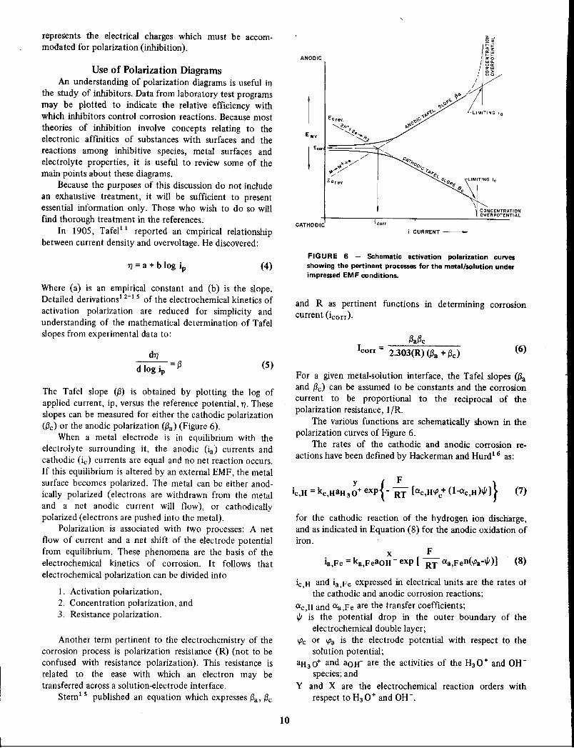
Use of Polarization DiagramsAn understanding of polarization diagrams is useful in
the study of inhibitors. Data from laboratory test programsmay be plotted to indicate the relative efficiency withwhich inhibitors control corrosion reactions. Because most
theories of inhibition involve concepts relating to theelectronic affinities of substances with surfaces and the
reactions among inhibitive species, metal surfaces andelectrolyte properties, it is useful to review some of themain points about these diagrams.
Because the purposes of this discussion do not include
an exhaustive treatment, it will be sufficient to presentessential information only. Those who wish to do so willfind thorough treatment in the references.
In 1905, Tafel11 reported an empirical relationshipbetween current density and overvoltage. He discovered:
ANODIC
CATHODIC icorr
II
/I
//1
L'TING '.
C4~
ItOOIC~4•.
~(
"(0 SIMITrNG ic
.o~.8c ~••••• \ CONCENTRATION
OVERPOTENTlAL
i CURRENT-
1) = a + b log ip (4)FIGURE 6 - Schematic activation polarization curvesshowing the pertinent processes for the metal/solution underimpressed EMF conditions.
Where (a) is an empirical constant and (b) is the slope.Detailed derivations1 2-15 of the electrochemical kinetics of
activation polarization are reduced for simplicity andunderstanding of the mathematical determination of Tafelslopes from experimental data to:
Another term pertinent to the electrochemistry of thecorrosion process is polarization resistance (R) (not to beconfused with resistance polarization). This resistance isrelated to the ease with which an electron may betransferred across a solution-electrode interface.
Stern 1 5 published an equation which expresses {3a,{3c
The Tafel slope ((3) is obtained by plotting the log ofapplied current, ip, versus the reference potential, 1). Theseslopes can be measured for either the cathodic polarization({3c)or the anodic polarization ({3a)(Figure 6).
When a metal electrode is in equilibrium with theelectrolyte surrounding it, the anodic (ia) currents andcathodic (ic) currents are equal and no net reaction occurs.If this equilibrium is altered by an external EMF, the metalsurface becomes polarized. The metal can be either anodically polarized (electrons are withdrawn from the metal
and a net anodic current will flow), or cathodicallypolarized (electrons are pushed into the metal).
Polarization is associated with two processes: A netflow of current and a net shift of the electrode potentialfrom equilibrium. These phenomena are the basis of theelectrochemical kinetics of corrosion. It follows that
electrochemical polarization can be divided into
I. Activation polarization,2. Concentration polarization, and3. Resistance polarization.
(6)(3a{3c
Icon = 2.303(R) ({3a+ (3c)
for the cathodic reaction of the hydrogen ion discharge,and as indicated in Equation (8) for the anodic oxidation ofiron.
x Fia,Fe = ka,FeaOH - exp [ RT aa,Fen('Pa-l/J)] (8)
ic,H and ia,Fe expressed in electrical units are the rates otthe cathodic and anodic corrosion reactions;
aC,H and aa,Fe are the transfer coefficients;l/J is the potential drop in the outer boundary of the
electrochemical double layer;'Pc or 'Pa is the electrode potential with respect to the
solution potential;
aH30+ and aOH- are the activities of the H30+ and OHspecies; and
Y and X are the electrochemical reaction orders with
respect to H3 0+ and OH-.
For a given metal-solution interface, the Tafel slopes ({3aand (3c) can be assumed to be constants and the corrosion
current to be proportional to the reciprocal of thepolarization resistance, I/R.
The various functions are schematic ally shown in thepolarization curves of Figure 6.
The rates of the cathodic and anodic corrosion re
actions have been defined by Hackerman and Hurd16 as:
and R as pertinent functions in determining corrosioncurrent (icorr).
(5)d1). = {3d log Ip
10

B
~ ,.•.••...
.•.••...
' F........*--------~------ "I .,------p I ,I ---~D---_1_----1-- -~
---~-----I-/:~II--- l- Gr I
~~/ I I~-Ai,:I Ai2i
Ai3---l
Ep
feorE
A
E
leorr icorr
FIGURE 7 - Anodic and cathodic polarization curves. A-Illustrates significant terms for freelycorroding metal. B-Schematic diagram showing relation of metallic corrosion, protection andinhibition.
•. f. A very useful review and derivation were published byMakrides.1 7 The chemical portion of the standard freeenergy of activation is included in terms ke and ka ofEquations (7) and (8).
Figure 7A illustrates the significant terms for a freelycorroding metal. The line EaD represents the anodicreactions; line EeD represents the cathodic reactions. Thepoint of intersection of anodic and cathodic reactions (D)establishes the open circuit corrosion potential (Eeorr) ofthe metal and indicates the magnitude of corrosion at ieorr(corrosion current).
Figure 7B is a schematic diagram showing the relationof metallic corrosion (D), protection (F and G) andinhibition (P). Generally, the immersed metal may becorroding by reactions under anodic control (Ea F) by useof anodic type inhibitors; under cathodic control (EcG) byuse of cathodic type inhibitors; or by mixed control(Ea-EeP) where the inhibitor controls both anodic andcathodic reactions. It is readily apparent that an inhibitorwhich can control both reactions is more effective. Note
that both anodic and cathodic type inhibitors reduce thecorrosion current (anodic: toil; cathodic: toi2), and that the"mixed" control inhibitor reduces the corrosion current
more effectively (toi3).
InhibitorsAn inhibitor is a chemical substance which, when
added in small concentrations to an environment, effectively checks, decreases, or prevents the reaction of themetal with the environment. Corrosion inhibitors are added
to many systems including: Cleaning pads, cooling sys-
tems, various refinery units, pipelines, chemical operations, steam generators, ballast tanks, oil and gas production units and many products that are marketed to thegeneral public. The corrosion inhibitor is of major significance for the preservation of metals. To be used effectively,the inhibitor must be compatible with the expectedenvironment, economical for the operation amenable totreatment, and one which will contribute the greatestdesired effect.
Inhibitors fall into several classes: 18 Passivators, precipitators, vapor phase, cathodic, anodic, neutralizing andabsorbants. While inorganic chemicals are certainly usefulfor controlling corrosion and can be classified as referenced
above, this discussion will be limited to organic chemicalsbecause of their primary importance as inhibitors and theirwide acceptance for preventing metallic corrosion.
An organic corrosion inhibitor can be classified as
anodic, cathodic, or both. Its classification dependsprimarily on its reaction at the metal surface and how thepotential on the metal is affected. The chemical structureof the inhibitor molecule plays a significant role and often
determines whether or not a compound will effectivelyinhibit a specific system.
Some organic inhibitor structures are presented in theAppendix as examples of several generic classifications.These are by no means comprehensive because the numberof inhibitor chemicals is legion. Even within this list,combinations of one structure with another (formation ofsaIt, or reaction product) can produce an inhibitor which iseven more effective than either chemical alone.
Effectiveness of inhibitors has been determined in
11);..,

FIGURE 8 - Constructions based on analine and thiobenzene.
Note: Same list as above replacing N with P, Sb, or As.Replace N in example aniline structure with P, Sb, or As.Also, aniline (N) could have these substitutions: HR, HX, R2'X2, or RX in place of H2.
All director groups apply to thiobenzene only, but positionsthey occupy on the aromatic structure are different. Thegroup listed under aniline as "ortho and para" now becomemeta directors attached to thiobenzene. Likewise, the metadirectors for aniline will be the ortho and para groups forthiobenzene. Also, the Sin thiobenzene can be replaced withselenium (Se), or tellurium (Te).
effective at very small concentrations and at a minimumsurface saturation.
Theoretical Aspects of Inhibition
Classifications
Corrosion inhibitors are not universally applicable, afact supported in some degree by the large number ofcompounds used and also by the fact that an inhibitoreffective in one system may not be effective in another.These complexities account in part for differing viewsabout types. One such division could be:
1. Those that form layers of considerable thickness.2. Those that form films by reactions with the
protected substrate, and3. Those which function by surface adsorption, with
no significant reaction with the substrate.The first two types are similar in that they may
describe reactions that occur naturally, as in the formationof rust on iron or oxides on aluminum of chromium. Inboth of these types, the protective layer involves anexchange of energy between the substrate and somecomponent in the electrolyte. For example, dissolvedoxygen in water combines readily with iron; iron may notcorrode at all in water with no dissolved oxygen. These tworeactions are concerned mainly with inorganic materials.Organic inhibitors usually are believed to inhibit byadsorption.
It is universally accepted that the organic moleculeinhibits corrosion by adsorbing at the metal-solutioninterface. However, the modes of adsorption are dependentupon:
1. The chemical structure of the molecule;2. The chemical composition of the solution;3. The nature of the met,!l surface; and4. The electrochemical potential at the metal-solution
interface.
NHR
NH2NR2
(CH2)n COOHn = 0,1,2,3
b. Meta
C2n02Rn = 1,2,3COX
CX2
CH2X
CH2CN
N02503HCHO
COR
Addition made with 0, m, p groupsuntil steric hindrance prevents!
R, C, thru C6, or 5NHCOR
NCOR
N(COR)2X(Halogen)
2. Thiobenzene
(CH)(2n_l)COOHn = 1,2,3C(2n-l)02Rn = 1,2,3CONH2
CONR2CONHR
5H (or 5e, Te in place of 5)
a. Ortho and/or P (Or'ara
1. Aniline
many ways and conclusions have been drawn as to thedetermining factors contributmg to effectiveness. Somegeneral concepts are:
1. The size of the organic molecule.2. The aromaticity and/or conjugated bonding.3. Carbon chain length.4. Bonding strength to metal substrate.5. The type and number of bonding atoms or groups in
the moledule (can be either 1r or a).
6. Ability for layer to become compact, or cross link(molecules effectively cover extra metal area throughshielding).
7. The ability to complex with the atom as a solidwithin the metal lattice, as recently learned.
Although all of these properties are important, none isas significant as one property which is a prerequisite if aninhibitor is to be effective: The structure must offerefficient solubility. In this way, the inhibitor can be
There are three principal types of adsorption associatedwith organic inhibitors:
1. 1r-bondorbital adsorption;2. Electrostatic adsorption; and3. Chemisorption
Adsorption of organic inhibitors usually involves at leasttwo types of adsorption simultaneously.
In addition to this classification is a recently discoveredmechanism by which an organic molecule prevents thecorrosion reaction: Organo metallic complex layer. Forexample, the inhibitor is an organic molecule which, whendissolved in hydrochloric acid, complexes with the steelsurface and forms a combination chemical-metal layerwhich provides both physical and chemical protection.
Inhibitor reactions are accomplished at low molecularconcentrations and may reduce steel corrosion in the rangeof 99%. This will be discussed further in inhibitor performance sections.
12

Influence of TemperatureLike most chemical reactions, the corrosion of iron and
steel by oxygen in aqueous solutions increases withincreased temperature in closed systems. In open systems,after an initial rapid increase the rate drops off after thesystem reaches about 90 C because of the reducedsolubility of oxygen in the water. Nevertheless, an increasein temperature will produce an increase in the corrosionrate in most systems. Sieverts and Lueg19 attributeddiminished effectiveness of inhibitors under the influence
of increasing temperatures to diminished coverage by theinhibitor. Their premise is based on the assumption thatmetal dissolution occurs on that part of the surface free ofadsorbed molecules. Riggs and Hurd20 took exception tothis premise and suggested that the measured corrosion rateis expressed more accurately as the sum of two rates:
(9)
Where
e is the fraction of the surface covered by the adsorbedinhibitor,
Kl is the rate constant for the uninhibited reaction, andKz is the rate constant for corrosion of the completely
covered surface.
They developed rate equations based on the Langmuiradsorption isotherm and used these as means of determining the temperature coefficient of corrosion inhibition.
Practical Application ConsiderationsPractical parameters to be considered before using the
organic molecule as an inhibitor include:1. Compatibility of the inhibitor molecule with the
system.2. A desirable, effective solubility.3. Temperature of system.4. The solution pH ,5. Diffusion rate through boundary layer.6. Various side effects.7. Economic analysis.Knowledge of the system's chemistry eliminates much
of the difficulty associated with the use of the organicinhibitor molecule. Following are abbreviated descriptionsof substances commonly found in many industrial environments which substances can affect the compatibility of the
organic inhibitor with its aqueous environment.
1. Metal Cations-Monovalent cations have nomeasurable effects on inhibitors. DIvalent cations may be
used with bicarbonates to form protective precipitates. Athigh concentrations, divalent cations interfere withinhibition by precipitating inhibitors such as phosphate(P04 =), silicate (Si03 =) and organic molecules such as thesulfonates (RS03 -).
2. Alkali, (OH-) - Corrosion of steel in alkalinesolutions is controlled by the rate of oxygen diffusion.Steel is easily passivated. Aluminum, zinc and lead corrodeslowly at low alkali concentrations, but above pH 9.0, theirrates are accelerated and inhibition is needed.
13
3. Chloride, (CI-) - Chloride ions are strongly adsorbed by steel, making it difficult to passivate. Therefore,the higher the concentration of the cWoride ion, the higherthe concentration of passivating inhibitor required.
4. Sulfate, (S04 =) - The effects of sulfate are not assevere and in many cases more beneficial than cWorides onpassivity. The sulfates may contribute to depassivation ifpermitted to concentrate (precipitate). Sulfates causecoagulation of certain aliphatic (long hydrocarbon chain)bactericides and corrosion inhibitors.
S. Bicarbonate, (HC03 -) - In hard waters, bicarbonates offer natural inhibition by forming mineralscales. In soft waters, corrosion inhibitors must be used dueto the acidic condition produced by excess carbon dioxide.
6. Sulfides, (S =) - Many metal ions are precipitated bysulfides. Oxidizing inhibitors are reduced by sulfide converting the sulfide to form free sulfur, so they can beeffective only if used in large concentrations. However,corrosion can be accelerated under these conditions.
7. Oxygen, (02) - If oxygen is lowered to less than0.1 ppm, this alone is sufficient corrosion control for mostsystems. Oxygen can support passivation of steel. Organicinhibitors are not generally effective against oxygen-causedcorrosion unless they contain passivating groups such asbenzoates or sulfonates.
8. Acid, (H+) - Corrosion rates are increased byincreased hydrogen ion concentration. Passivating inhibitorsare used in sulfuric (Hz S04) and phosphoric acids (H3 P04 )but not in hydrochloric (Hel). Nonpassivating organic orcathodic inhibitors (e.g., guanidine, propargyl alcohol andpyridines are preferred in pickling acids).
9. Naphthenic Acids, (R-COOH) - In basic waters,these substances can support natural inhibition. In acidicsystems, inhibitors are generally added to control m~talliccorrosion. They affect interfacial tensions.
Designing InhibitorsA careful examination of the literature (see bibli
ography) will inform anyone familiar with corrosionprocesses and organic chemistry as to pertinent factors indesigning an organic corrosion inhibitor. The theoreticalexplanations of inhibitor function are in common agreement that adsorption phenomena involve:
1. Proton acceptors;2. Electron acceptors; and3. "Mixed" molecules.
1. Proton Acceptors - The organic structures that fitthis group can be generally considered as cathodic siteadsorbers. Materials in this group accept the hydrogen ionor proton and migrate to the cathode. Organic inhibitorsused in various acidic environments are included. Examplesare: Anilines, quinolines, ureas and aliphatic amines.
2. Electron Acceptors - Materials in this group aregenerally effective at anodic sites. They function asinhibitors due to their ability to accept electrons, and aremost effective for corrosion reactions under anodic control.
In addition to anodic inhibitors, passivating inhibitors arefound within this group. Examples are: Organic peroxides,

organic thiols and selenols and the inorganic chromates andnitrites.
3. "Mixed" Molecules - These are organic moleculeswith more than one orienting group attached (i.e., -NH2and -SH). They have the following possible characteristics:
1. One basic molecule may contain structures commonto both orienting groups (i.e., amine benzenethiol),
2. Salt formed by proton and electron acceptororienting groups from two separate molecules (i.e., benzenethiol and aniline), and
3. The reaction product of organic structures whichcan form "organic ions" in acidic systems (i.e., pyridiniumbenzyl bromide).
Due to their ability to affect both anodic and cathodicprocesses of corrosion, these structures are classified as"ambiodic" inhibitors.
It appears likely then that the most effective organicinhibitor is one whose electron density distribution causesinhibitor to be attracted to both anodic and cathodic areas.
Riggs and Every21 determined why certain compounds, orgroups of compounds, were effective as anodic and/orcathodic inhibitors of metallic corrosion. Using the simplerstructures of aniline and benzenethiol, they developed themechanics for designing organic molecules which preventedcarbon steel corrosion in hydrochloric acid.
o. Anodic Function
Benzenethiol exhibits a high electron density about thesulfur and assumes a slight negative charge in acidicenvironments.
00O-
H 0S
00
00 0
@0-
o Denotes orbital electrons
Thiobenzene is a chemical which meets the requirement-source of available electrons. If the electron densitycould be enhanced in some manner, an increased anodic
inhibitory effect might be experienced. Some methods forpossibly increasing electron density follow:
(l) Use a di- or tri- thiol, assuming that utilization ofthe inhibitor electrons is not sterically limited to a singleposition.
(2) Addition of a cOnstituent to the ring to stabilizethe electron density about the sui fur (or sulfurs).
(3) Addition of a constituent to the ring to directpermanent electron inductive effect toward the benzenering and the suifur (or sulfurs).
(4) Addition of a constituent to the ring to aid theinductometric effect when the thiol is close to the metalsurface.
(5) Addition of a constituent to the suifur (or sulfurs)to: (a) stabilize the electron density of the thiol;(b) give a
14
permanent inductive effect; or (c) have an inductometriceffect on the suifur .
b. Cathodic Function
Aniline is an inhibitor for acid media. Assumptions forelectron attraction forces which cause a chemical to
function as a cathodic inhibitor may be exemplified withthis structure.
o Denotes orbital electrons
Aniline assumes a small positive charge in acid. Itfollows that if the acceptor characteristics of aniline couldbe increased, the inhibitory character of the structure couldbe made more effective at the same time. Some of the waysthis can be accomplished are:
(1) Use of di- or tri- amino groups, since an electronacceptor is probably not sterically limited to a singleposition.
(2) Addition of a constituent to the ring to stabilizethe electron acceptor characteristics of the amino group (orgroups).
(3) Addition of a constituent to the ring to give apermanent electron inductive effect away from the aminogroup (or groups).
(4) Addition of a constituent to the ring to cause aninductomeric effect away from the benzene ring and/oramino group (or groups).
(5) Addition of a constituent to the amino group (orgroups) to accomplish any (or all) of the above fourobjectives.
c. Ambiodic Function
In the third case, a single chemical (or combination ofselected chemicals) also may exist which could act as bothanodic and cathodic inhibitor (an ambiodic inhibitor). Suchan inhibitor would act in an inductomeric manner, with
either electron acceptor or donor characteristics beingpredominant, depending upon the properties of the system.A chemical exemplifying this property is 2-aminobenzenethiol.
o 0H 0 ·N 0 Ho 0o 0
H
o Denotes orbital electrons

FIGURE 9 - Polarization curves for 99.9% Fe wires in 6NHCI at 30 C. (Hackerman, Hurd and Annand. Corrosion,January, 19621.
FIGURE 10 - Polarization curves for uninhibited monomwand polymer solutions; b/Jr-o.1 M 4-ethylpyridine in 1N HQ;0.0-1 N HQ uninhibited; "e-o.031 M poly(vinylpyriclne)512 MW in 1N HCI. (Annand, Hurd and Hack.lNn. J.Electrochem. Soc., 112, 2, 19651.
-800
-060 -062H2 EVOLVES~
-700-600-500
-054 -056 -058POTENTIAL (V vs. SCE)
POTENTIAL vs. S.C.E.
-400
11 11
-300-200
10-048 -050 -052-- Fe DISSOLVES
10-11"""(5
10"
10
10009876500..
4:lE 0'-III...:lEC"- 2>-' •...0;z•••0
•...100z '"
9'"
8'" :::>70 6
5043I Ir I.
2
15
The 2-aminobenzenethiol seems appropriately designedto function as both anodic and cathodic inhibitor (anambiodic inhibitor). This structure or like structures would
also lend themselves to improvement by methods previously outlined.
Based on the assumptions made in these three cases, itwas predicted that the comparative inhibiting effectivenessof the relevant organic compounds would increase.
The orienting groups which effect the electron densityindicate the multitude of organic molecules which arepossible corrosion inhibitors. Considering the two ex
amples, one can produce "tailor-made inhibitors" byfollowing this pattern. Development of formulations based
on aniline and thiobenzene are indicated in Figure 8.
d. Inhibitor Performance
The theory of corrosion inhibition provides the logicfor making reasonable decisions for best solutions to
corrosion problems. However, as suggested previously,certain practical considerations are encountered when
actual corrosion treatment begins. In other words, theoryoffers excellent guidelines, but the value of the organicmolecule for corrosion inhibition is not proved until it isperformance tested. This section will demonstrate theperformance of several organic molecules, tested undervarious conditions by many corrosion scientists.
Hackerman,22-24 Hurd, Annand, and Aramaki published a series of papers on polymethyleneimines asinhibitors of steel corrosion in hydrocWoric acid. Initially,galvanostatic polarization curves were determined for steelin uninhibited hydrocWoric acid solutions and in hydrochloric acid which contained various amounts of the
polymethyleneimines. Figure 9 is representative of theinformation gained in their study. The 1% nonamethyleneimine effectively reduced the corrosion current (corrosionrate) by one order of magnitude. Significant to the surfaceeffect of polymethyleneimines were the well defined Tafelregions which extended well past the one decade.
These studies were extended to include polymericamines and the results justified their assumption thatsoluble polymeric molecules containing multiple repeatingunits identical in functionality were more efficient corrosion inhibitors than the corresponding monomers. Figure10 illustrates this. Poly (vinyl pyridine), O.031M wasconsiderably more effective than the 4-ethylpyridine, whichwas used at 3 times the concentration. Also noteworthy,was the greater effect polyvinyl pyridine exhibited on thereduction reaction (strong cathodic inhibitor).
The inhibitive effect of medium sized polymethyleneimines on the corrosion of iron in a hydrocWoric acidsolution was stated to be related to the angle C-N-C bondor to strain in the ring. The authors said that this organicstructure's effectiveness was caused by the donation of theunshared 1T-electron pair of its nitrogen atom to the metal.Further, they did not believe the primary cause ofimproved inhibition was due to molecular size. An exception to this position may be in the replot of data theyreported for dimethylpolymethylene ammonium cWoride

(Figure 11). The log of corrosion current was replotted as afunction of (n), the number of repeating methylene groupsin the molecule. The concentration of the various imines
was held constant. These data graphically support themolecular size concept for increased inhibitor effectiveness.However, they also support the electron density concept
FIGURE 11 - Effect of molecular size on inhibition of
dimethyl~lymethylene ammonium chloride,: (CH2)n~ +(CH3)2 Cl (Aramaki and Hackerman. J. Electrachem. ac.,116, May,1969).
54
pH
o 0.3
o 1.0
32
INHIBITOR CONCENTRATION (mMI
oo
FIGURE 13 - Langmuir adsorption isotherm for adsorptionof aminoazophenylene. (Chin and Nobel
2
3
4
5
which improves both the adsorption and/or complexingproperties of the imines.
Okamot025 reported results using rapid polarizationtechniques during the study of mild steel corroding ininhibited sulfuric acid. Dibutyl thioether displaced theanodic Tafel slope toward the noble potential direction.Figure 12 illustrates this effect. There are well-definedgalvanostatic polarization~urves for mild steel in 10%
sulfuric acid with molar concentrations of dibutylthioetherranging from 1.0 x 10⁻³ to 5.0 X 10⁻³. In both cases [(1)the imines, and (2) the thioethers), the data were consistent with the before-mentioned concept for designinginhibitors by selection of orienting director groups.
Interpretation of adsorbent type organic inhibitors'performance data can be enhanced by "fitting" these datato one of the three adsorption isotherms in Table 1. Chinand Nobe26 studied the electrochemical characteristics of
iron in sulfuric acid, determining the various inhibitorycharacteristics of aminoazophenylene. Their data wereconsistent with the slow proton discharge step for the ironreduction reaction. Surface coverages were determinedfrom capacitance measurements and were consistent withthe corrosion rates, which made extremely significant fitsto Langmuir adsorption isotherms. Figure 13 is the isotherm plot for the adsorption of aminoazophenylene oniron in sulfuric acid. These data correlated in systems at pH0.3 and at pH 1.0. The adsorption constant, K = 104 M-I,indicated that aminoazophenylene was strongly adsorbedon the iron surface. The inhibiting effectiveness of theaminoazophenylene could be increased by quaternizingwith dimethylbenzylbromide.
Meakins27 experimented with n-alkylquaternaryammonium compounds as inhibitors of sulfuric acid corrosion of steel. The inhibition effectiveness increased regularly with the lengthening of the alkyl chain. Generally, the
18
10
1512
o1.0x10-32.05.0
9n
6
0.1 1.0ClfRRENT DENSITY. mA/cm
3
1234
0.01
+2
-0.40
-0.70
-0.60
-a.so
-0.30,
FIGURE 12 - Polarization curves obtained by the rapidmethod for a mild steel in 10% sulfuric acid containingvarious concentrations of dibutylthioether; 30 C dibutylthioether (M). (Okamoto, Nagayama, Kato and Baba).
+1
N ~E0u.-'"0..J 0
16

LOG CONCENTRATION OF QUATERNARY AMMONIUM INHIBITOR (MOLAR)
-I-2-3-4-5-6
1-4
1- 21-00-80-6
Q; ~.•...• 0-4-'"0.J
0-2
0-0-0-2-0-4
FIGURE 14 - Dependence of log ((}!1-(}1 on concentration
of quaternary trimethyl-ammonium compound in N-H2S04at 20 C. (Meakins)
Recent data of the author's were obtained on the
inhibition of carbon steel corrosion by sulfuric acid. Hoarand Holiday28 reported on the inhibitor, quinoline and thecorresponding corrosion rate data as applied to theLangmuir equation. Quinoline was quaternized withdodecyl benzyl chloride and used at various concentrationsto inhibit carbon steel in sulfuric acid at 80 C (Figure 15).The quinolinium quaternary was far superior to thequinoline alone. The corrosion rate data fit the isothermvery well for inhibitor concentrations up to 10-3 M. Theshape of the isotherm for the quaternary indicates persistent adsorption at all concentrations.
Riggs and Hurd20 also reported on the inhibition ofsteel corrosion in hydrochloric acid by quaternary typeamines which used polar head-groups of pyridine and
quinoline. Figure 16 is representative of the Langmuir typeplots from their corrosion rate data. They were able toobtain Arrhenius plots and determine temperature coefficients and activation energies. It is recognized that everyeffective corrosion inhibitor may not provide data whichfitted the Langmuir adsorption isotherm. It is suggestedthat when this occurs, the inhibitor is generally:
1. Very strongly adsorbed,
2. Resistant to desorption, and3. Capable of service at higher temperatures.Based on these facts, low concentration effects often
outweigh the importance of "complete" inhibition. Corrosion rate data can be fitted to the Ternkin equation and theeffective inhibitors can be immediately "performance-
17
RT
qmQ: Log C
An invariable test for Temkin data is obtained by plotting ()against Log C.
RT
() = --LnAopqoa
qo is the heat of adsorptiona is a constant
equating Ln (}!11-8) to zero. the equation simplifies to:
RT RT
Log () = - Log ao +-- Log P.qm qm
Temkin
or
A set of experimental data can be tested to obey the Freundlich
isotherm by plotting Log () against Log p.
Freundlich
()
plotted Log 1-8 against Log C
Inhibited Rate
1-8 = 1 - U 0 hObo d R The Langmuir Isotherm is usuallyn1n lite ate
() = Degree of Inhibition (% Protection)
Langmuir
C = Inhibitor Concentration (Moles!literl
() q
Log ~ = Log A + Log C - 2.303 RT
TABLE 1 - Adsorption Isotherms
or
()
"1-8 = ACe -q!RT
quaternary amine was much more effective than the
primary amines, due to the better solubility of the higherhomologues. He reported the dependence of log (()/ 1-8) onthe concentration of quaternary trimethylammonium compounds in IN H2804 at 20 C [see Figure 14 and Table 1(Langmuir Isotherm)] . The relationships lose linearity withincreasing alkyl chain lengths, so the Langmuir adsorptionequation does not apply, neither can these data be used toobtain heats of adsorption for the inhibitors. However, theperformance data were significant and pointed not only tothe effective contribution of alkyl chain length but also tothe effect of varying the polar head-group.

40·C ~6000830 C
10-5
0.2
0.3
0.0
0.1
0.999
o.~o
0.09
0.99
0.90
-I-2-5 -4 -3LOG C OF INHIBITOR
-7
-,
+1
FIGURE 15 - Langmuir adsorption isotherm for quinolinecompounds on steel in 5% H2S04. O-Quinoline 70 C,H2S04, 5% (T. P. Hoar. J. Applied Chem., 3, November, 91953). b.-Oodecylbenzyl quinolinium chloride (0. L Riggs,Jr.)
eoJ
eoJ
lOG C
-5 -4 -, -2LOG MOLARITY
FIGURE 16 - Langmuir type plot of corrosion data.Quinoline in 2N HCI.
FIGURE 17 - Temkin adsorption isotherms of N-hexadecylpyridinium chloride on 1020 carbon steel in 2N HCI.
screened" at the lower concentrations. Corrosion rate data
for carbon steel in 2N hydrocWoric acid at 40, 60 and 83 Care fitted to the Temkin equation in Figure 17 andgraphically demonstrated effectiveness of low inhibitorconcentration. Also, these data suggest that N-hexadecylpridinium cWoride accelerates corrosion at the lowerlimiting concentrations.
The effectiveness of N-hexadecylpropylene diamine asan inhibitor for carbon steel corrosion in aqueous environments containing hydrogen sulfide and/or carbon dioxidecan be improved by the addition of ethylene oxide to theinhibitor molecule. Figure 18 shows the inhibition affordedat a concentration of 25 ppm of the aliphatic diamine as afunction of the number of moles of ethylene oxide added.The maximum inhibition was reached for steel in either
H2 S or CO2 environment with the addition only 2 molesethylene oxide. The effectiveness of the original diaminewas decreased when ethylene oxide was added in excess of5 mols.
The addition of benzoic acid with an orthohydroxy
group to the N-hexadecyl propylene diamine provides anorganic structure which was highly effective as a corrosioninhibitor for steel in hydrogen sulfide-saturated brine.29
Inhibitors in Hydrochloric AcidThe selection of inhibitors for use in hydrocWoric acid
baths for pickling steel is of substantial economic importance. It is generally accepted that the more effectiveorganic inhibitors retard mill scale removal during the acidpickling process. Riggs and Hurd30 found this to be truewith the major pickling acid inhibitor (Figure 19). Theyalso determined that certain additional benefits were gainedfrom the use of dodecyl benzyl aromatic amine typequaternaries. These types of organic structures not onlyremoved the mill scale in less time; they effectively cleanedthe steel surface at lower temperatures than normallyoperational and also succeeded in preventing the corrosionof the bare steel surface.
Compatibility of an organic molecule with the prospective environment is a prime factor in achieving inhibition.
18

FIGURE 18 - Effect of ethylene oxide addition on inhibition of an alkyl diamine (25 ppmconcentration). O-H2S, 5% NaCI brine; .6.-C02, 5% NaCI brine;
1614
97.194.592.387.086.187.2
1210
Li DB 503Na DB 503K DB 503Ca (DB 503)2Ba (DB 503)2Mg (DB 503)2
8
Length of Test - 168 HoursPercent
Protection
TABLE 2 - Inhibition of Carbon Steel
Corrosion in Sea Water by AlkalineEarth Dodecyl Benzene Sulfonates
(neutralizes only one sulfonic acid molecule) providedcorrosion inhibition greater than 90%. The divalent alkalineearths (neutralizes two sulfonic acid molecules) were largelyineffective. Coagulation was observed at the sea water-airinterface.
Certain organic molecules which exhibit all the electrondensity characteristics of ambiodic type inhibitors doindeed control the corrosion reaction, but do so bycomplexing with the metal atom while still in its solidlattice. These complexing reactions do not create a bulklayer phase, but remain at submicroscopic thicknesses. Theproduct cannot be removed by scraping because if this isattempted, the metal surface will be scratched. Thesurface complex is highly resistant not only to the acidenvironment from which it was formed, but provides anexcellent barrier to oxidation by moist air which cancontain various pollutants such as the oxides of nitrogen orsulfur.
The structures that exhibit this capability are similar tothat of 3,5-diaminobenzoic acid. 0
I C - OH
,...@...
19
95
6
Additional Mols of Ethylene Oxide
DodecylbenzylPyridinum Chloride
4
• 200ppm 0• 500ppm 0•. 1000ppm 6
-1- No Inhibitor
AlkylbenzylAmine Residuals
75Temperature
2
65
C16H33I
Inhibitor: HN-[CH2] 3 NH2
/"// ,,
/,//~
2055
60o
100
FIGURE 19 - Effect of inhibitor concentration on descalingof carbon steel in 10% HCt at various temperatures.
c> 0g .~.~ e.~ 0.•... ~.•... "-UJ •.• 80~ co Q)•.. ":0 ~:co...c ~- '"
60
The structure may be an effective corrosion inhibitor in onesystem and ineffective in a similar environment. Such is thecase for the N-hexadecyl propylene diamino salicylate. Aslong as the environment contains very low sulfate concentration, the inhibitor is effective. However, higher sulfateconcentrations render the inhibitor ineffective. The sulfatedisplaces the salicylic acid component complexes with theN-hexadecyl propylene diamine and separates from theaqueous phase as a coagulant.
Also, the organic structure may be designed so that itis too "large" to dissolve in the proposed system. Alkalineearth organic sulfonates are well known for inhibitingcorrosion of steel in aerated waters. Table 2 lists the testresults of carbon steel exposed 168-hours in sea waterswhich had been treated with I% dispersions of organicsulfonates. In each instance, the monovalent alkaline earth

TABLE 3 - Effectiveness of 3,5-Diaminobenzoic Acid
for Inhibiting Carbon Steel Corrosion by 10"10 Hydrochloric Acid at 25 C
and the Subsequent Corrosion Resistance of Formed Complex
Complexed Steel Surface3,5-diaminobenzoic
Moist Brine AtmosphereAcid
Percent Original wlowlo Concentration
InhibitionDays0.10.51.0
0.1
92.07ExcelExcelExcel0.5
93.014ExcelExcelExcel1.0
95.030GoodExcelExcel90
GoodExcelExcel
When carbon steel was exposed to a 10% hydrochloricacid solution with either 0.1, 0.5 or 1.0 wlo aminobenzoic
acid present, the surface complex formed in a matter ofseconds. Its thickness growth appears to be self-limiting.Table 3 lists the corrosion data both for carbon steel
exposure to the 10% hydrochloric acid and the subsequentcomplexed surface exposure to moist air. Excellent inhibition was experienced during acid testing. The evaluationof the complex was made visually. No rusting was observedfor the "excellent" ratings. Only minor surface discoloration (3 or 4 very small spots) was noted for the "good"ratings.
Many inhibitors for a wide range of metals andenvironments have been tabulated in a checklise 1 which
can serve as a guideline for doubtful treating situations.
e. Measuring Inhibition
Both corrosion and its inhibition have long beenevaluated by one of several techniques: Visual, solublemetal ion analysis, calipers and metal test strips. Recently,methods have been used which are based on electro
chemical concepts using instruments that provide corrosionrate values from test probes exposed in the environment.These rates are a function either of cross sectional
resistance or resistance to polarization.The corrosion process is recognized not to be con
trolled by both thermodynamic and kinetic factors, andso, is often rate dominated. The instruments havedesigned into their circuits a variable time sequence forsurface polarization and herein lies the problem. Allcorrosion processes do not proceed under the control of the
same reaction process or reaction rates. Many corrosivesystems in which the probes are exposed provide corrosionproducts which remain intimate to the test probe andcontribute to the measurement errors recorded by theinstrument. While the surface exposed to the environmentmay be slowly going into solution, the zone between thebase metal and the corrosion product can be very active.The reverse situation also may exist. This time factor canreadily be accommodated in laboratory experiments, but isa major handicap to field or plant measurements.
It has been suggested32 that these measurement errorscan be corrected by determining the value of the slopewhich results from plotting the reference potential change(while electrodes are under constant current conditions wellbelow the 10 mv polarization level) as a function of the logof time in minutes. This corrosion factor is used in the
electrochemical equation for corrosion rate calculations.Electrochemical instruments offer by far the most
convenient method known today for monitoring in-plantcorrosion. In spite of the above disadvantage, the advantages are numerous and have helped widen their use.Although specific values for rates of corrosion may beunavailable, relative performance of both materials andchemical inhibitors may be more important. The instruments register changes quickly, either upsets in operation,or inhibitor effects. They are extremely useful as tools formass screening of prospective treating compounds. Theyhave the capability of providing continuous rate values.This is most advantageous, in light of the long exposuretimes required to obtain a single corrosion rate value fromexposed metal strips.
CHIIICI
CHt>H
PROPARGYL ALCOHOL
Organic Inhibitor Structures
CH20HICIIICICH20H
2-BUTYNE-I, 4- DIOL
20
HZC-N(CZH5)ZICIIIC1
He-OHICH3
5- 01ETHYLAM I NO-4- PENTYNE-Z- OL

OH 0d-q~ ~ C,ONa
CH3IHC-N-CH2'~
I H -
CIIICH
SODIUM SALICYLATE
ACRYLIC ACID
n-VALERIC ACID
ALKENYL SUCCINIC ACID
3-BENZYLAMINO+BUTYNE
ACETIC ACID
PROPARGYL CAPROATE
21
#0~C,~ ONa
SODIUM BENZOATE
SUCCINIC ACID
n - CAPRYLIC ACID
n-BUTYRIC ACID
FURFURALDEHYDE
0-1C,O"HC
PROPARGYL QUINOLlNIUM BROMIDE
DIPROPARGYL THIOETHER
CH3 CH3I /H
HC-N-C,I H CH3CIIICH
9,1I-0CTADECADIENOIC ACID
(DIMER OF LINOLEIC ACID)
MALEIC ACID
PROPIONI C AC I 0
n- CAPROIC ACID
CINNAMIC ALDEHYDE
DIPROPARGYL ETHER
3-ISOPROPYLAMINO-I- BUTYNE

~O~ CH::;CH-C,~. ONa
SODlUM CINNAMATE
CH3-CH2- N H2
ETHYLAMINE
n- OCTYLAMINE
ALLYLAMINE
CH3-CH2-CH2-NH2
n - PROPYLAMINE
n - DECYLAMI NE
METHYLAMINE
n- BUTYLAMINE
n - TETRADECYLAMINE
n - OCTADECYLAMINE
METHYLPROPYLAMINE
DIAMYLAMINE
TRIPROPYLAMANE
HEXAMETHYLENEIMINE
N-HEXADYCYL PROPYLENEDIAMINE
DIETHYLAMINE
DI-n-OCTYLAMINE
CH3-(CH2)3 "CHr(CH2)3-N /CHr(CH2)3
TRI BUTYLAMI NE
22
N - DODECYL B - METHYLEN EDIAMINE
DIBUTYLAMINE
TRIETHYLAMINE
CH3 -(CH2)7 '\CH3-(CH2)7-N/CH3-(CH2)7
TRI-n -OCTYLAMINE
d-OXIMINO-~~VINYL QUINUCLIDIN E

DOoECYLBENZYLQUINOLlNIUM BROMIDE
DIOCTADECYLDIMETHYLAMMONIUMCHLORIDE
I-ETHYLAMINO2-0CTADECYLI MIDAZOLINE
HN N
V-)NHIC2H5
6-N-ETHYL PURINE
oECAMETHYLENE b;s-DIMETHYLHEXADECYL AMMONIUM BROMIDE
HEXAoECYLPYRIDINIUM IODIDE
9NH2
ANILINE
H2N-(CH2)2, H2N- (CH2 )2-NH '\..H2N- (CH2)2- NH- (CH2)2NH
(CH2)2~HH2N- (CH2)2/
H2N- (C H2)2 -NH/H2N- (CH2)2- NH-(CHz.>~
01ETHYLENETRIAMINE
TRIETHYLENETETRAMINET ETRAETH YLE NEPENTAMI NE
H2C- N(tJI 11
HOCH~H2NH2H2C, "c- CI8H:n NNI HCH2-CH2-0H
1- HYDROXYETHYL
BENZOTRIAZOLEMONOETHANOLAMINE2-0CTAoECYLlMIDAZOLlNE
HO-CHZ-CHZ'
HOCHlCH2"-./CH2-CH2NH
HOCH2CH2-No 'NH
/ HOCH2CH2/" /
HO-CHl-CH2 CH2-CH2
olETHANOLAMINE
TRI ETHANOLAMINEMORPHOLINE
H2N -CH2-CH2"",
HlN-CHl-CH2'\.<:::>......... NHNH
HlN-CHl-CH2- NHO-CH2-CH2//' /HO-CH2-CH2
HO-CH2-CH2
AMIN OETHYLETHANOLAMINE
DIAMINOETHANOLAMINEPHENYLETHANOLAMINE
23
TETRABUTYLAMMONI UM CHLORIDE
DOoECYLBENZYLolM ETHYL AM MONIUMCHLORI DE

OH
~-CH2-CH2-0H< ~NH2HO-<:>-NH2HO-CH2-CH~
PHENYLDI ETHANOLAM I N E
m-AMINOPHENOLP-AMINOPHENOL
0
0
?OH.
/
~
(/'\XiI B OH NH2N NH2
OH
3,~-DIAMINOBENZOIC ACID
NICOTINIC ACIDB- HYDROXYQUI NOLINE
HEXA METHYLENEI MINEBENZOATE
0 O-CH3o-CH3N
N N
PYRIDINE
2-PICOLlNE3-PICOLlNE
CH3
CH3
62-CH36 ~CH3N
N N
4-PICOLINE
2,4-LUTIDINE4 - ETHYLPYRI 01 NE
~~-CHZ-~-CH2-')
COH c-CO-~ !J
3 ~ rf CH3
N N n
N
POLY- (4-VI NYLPYRI 01 NE)
QUI NOLI NE2,6- DIMETHYLQUINOLINE
H
H
xgN
®fJ( - ~ ~IN ,,~ACRIDINE
IMIDAZOLE4,5-DIPHENYLI MIDAZOLE
(J;(Aj~S'-<~N
N IH CH3
BENZIMIDAZOLE
1- METHYLBENZ I M IDAZOLEI-PHENYLBENZIMIDAZOLE
24
DECAMETHYLENEI MI NE

BUTYLNITRITE
m-TOLUIDINE
DIPHENYLSULFIDE
01CYCLOHEXYLAM I NE
25
CYCLOHEXYLAMINE
o-TOLUIDINE
/CH2-CH2
H~, /CHCH2-CH2 "\
NH '·H-r.r04CH2-CH2 / ,,-/ "
H2C, /CHCH2-CH2
DICYCLOHEXYLAMINE CHROMATE
ETHYL-n-OCTYL SULFIDE
~/R~-,p N'R
CH3-(CH2)9,S
CH3-(CH2)9/
01DECYLSULFI DE
N, N-DIALKYLANILI NER=METHYL OR ETHYL
A-N\A}-< »NH
2-PHENYLBENZIMIDAZOLE
CH2-SH
CH3-(CH2)3-S H
CH3-(CH2)II-SHr;BUTYLMERCAPTAN
LAURYLMERCAPTANBENZYLM ERCAPTAN
SH
O'CH2-CH.-SH0Q-CH'
I' b SHPHENYLETHYLMERCAPTAN
THIOPHENOLo-THIOCRESOL
([CH.
CH3-CH2H3C
"S
)cH-CH2H3C "-/ C /SCH3-CH2
H3 'CH-CHSH H C..•..• 23m-THIOCRESOL
DIETHYLSULFIDE01- sec-BUTYLSULFI DE
/CH2-C~H2C /CH
"c: H2- CH2 '"NH·HN02
/CH2-C~ /
H2C", /CHCH2-CH2
DICYCLOHEXYLAMINE NITRITE

PHENYLBENZYL SULFIDE
DIMETHYSULFOXIDE
01PHEN YLSULFOXI DE
DIBENZYLSULFI DE
DI-n- BUTYLSULFOXIDE
DI-p-TOLYLSULFOXI DE
OH OH OH
H3C-{\- -s-0-S-1\CH3y H3C-VCH3 YCH n CH3
XYLENOL POLYSULFIDE
TETRAMETHYLENESULFOXIDE
o
«:>-CH2-~-CHrO
01 BENZYLSULFOXI DE
ETHYLENE6L YCOLbis-DI BENZYLXANTHATE
01METHY LOCTADECYLPHOSPHON IUMBROMIDE
TETRAPHENYLPHOSPHONIUM
CHLORIDE
TRIPHENYLBENZYLPHOSPHONIUMCHLORIDE
DIETHYL HUOPHOSPHATE
Se11
H2N-C-NH2
SELENOUREA
C>-~HC=SINH2
TETRAPHENYLARSONIUMCHLORI DE
DIOCTYLTHIOPHOSPHATE
SH2N-C-NH2
THIOUREA
TRI PHENYLBENZYLARSONIUMCHLORI DE
TRIBUTYLSELENOPHOSPHATE
CHZ=CH-CH2-NH IC=SINH2
ALLYL THIOUREA
I\-NV\;-SH
PHENYLTHIOUREA 1,3- DIPHENYLTHIOUREA
26
2-MERCAPTOBENZOTHIAZOLE

References1. The Van Nostrand Chemist's Dictionary. 3rd Printing, D. Van
Nostrand Co., Inc., Princeton, N. J., October, 1956.The Corrosion Handbook. H. H. Uhlig, ed. 2nd Printing, JohnWiley & Sons, Inc., New York, September, 1948.The Corrosion and Oxidation of Metals. J. R. Evans. 1stPrinting, Edward Arnold, London, 1960.Glossary of Conosion Terms. Materials Protection, 7, No. 10,68·71 (1968) October.Glossary of Terms Used in Maintenance Painting (NACET·60-12). Materials Protection, 4, No. 1, 73·80 (1965) January.Corrosion and Corrosion Control. H. H. Uhlig, 4th Printing,John WHey & Sons, Inc., New York, p. 224, March, 1967.
2. Double Layer and Electrode Kinetics. Paul Delahay, John WHey& Sons, Inc., New York, N. Y., p. 36, 1965.
3. D. C. Grahame. Chemical Reviews, 41,441 (1947).4. Molecular Designing of Organic Corrosion Inhibitors. Z. A.
Fouroulis. Symposium on the Coupling of Basic and AppliedResearch, 1966. NACE, Houston, Texas, p. 26.
5. S. Levine, J. Mingins, and G. M. Bell. J. Electroanal. Chem., 13,280·329 (1967).
6. J. A. V. Butler. Electrocapiliarity. Chemical Publishing Co.,1940.
7. J. M. West. Electrodeposition & Corrosion Processes. Chapter 1,D. Van Nostrand Co., London, 1965.
8. C. F. Pruton and S. H. Maron. Fundamental Principles of
Physical Chemistry. The MacMillan Co., New York, Chapter Xl,p. 309, 1947.
9. F. H. Getman and F. Daniels. Outlines of Physical Chemistry,7th Edition, John Wiley & Sons, Inc., New York, Chapter VII,p. 132, 1947.
10. S. Glasstone. Textbook of Physical Chemistry, 2nd Edition, D.Van Nostrand Co., Inc., New York, p. 229, 1948.
11. J. Tafe!. Z. Fur Physiki. Chemie., 641-712 (1905).12. Modern Aspects of Electrochemistry. J. O. M. Bockris, Butter·
worth Scientific Publications, London, p. 180, 1954.
27
13. J. A. V. Butler. Trans. Faraday Soc., 19,729-734 (1924).14. Electrochemical Kinetics. K. J. Vetter. Academic Press, New
York, 1967.15. M. Stern and A. L. Geary. J. Electrochem. Soc., 104, No. 1
(1957).16. N. Hackerman and R. M. Hurd. First International Congress on
Metallic Corrosion, Butterworths, London, p. 313, 1962.
17. A. C. Makrides. Corrosion, 18, 338t-349t (1962) September.18. E. S. Snavely and N. Hackerman. NACE Basic Corrosion
Course, NACE, Houston, Texas. Chaoter 9,1970
19. A. Sieverts and P. Lueg. Z. Anorg. Chem., 126, 192 (1923).
20. O. L. Riggs, Jr. and R. M. Hurd. Corrosion, 23, 8, 252-258(1967) August.
21. O. L. Riggs and R. L. Every. Corrosion, 18,7, 262t-269t (1962)July.
22. N. Hackerman, R. M. Hurd, and R. R. Annand. Corrosion, 18,(1962) January.
23. R. R. Annand, R. M. Hurd, and N. Hackerman. J. Electrochem.Soc., 112,2 (1965) February.
24. K. Aramaki and N. Hackerman. J. Electrochem. Soc., 116,5(1969) May.
25. G. Okamoto, M. Nagayame, J. Kato, and T. Baba. CorrosionScience, 2,21-27 (1961).
26. R. J. Chin and K. Nobe. J. Electrochem. Soc., 118,4 (1971)April.
27. R. 1. Meakins. 1. Appl. Chem., 13,339 (1963) August.28. T. P. Hoar and R. D. Holiday. J. Appl. Chem., 3, 502 (1953)
November.
29. O. L. Riggs, Jr. and F. 1. Radd. Corrosion, 19, 1 (1963)January.
30. O. L. Riggs, Jr. and R. M. Hurd. Corrosion, 24, 2 (1968)February.
31. M. Brooke. Chem. Eng., 69 (1962).32. O. L. Riggs, Jr. Corrosion, 26,8 (1970) August.

E. SCHASCHL*
Methods for Evaluation and Testingof Corrosion Inhibitors
IntroductionA corrosion inhibitor consists of a chemical added to a
system of interest at a very low concentration, at whichconcentration, it has a significant effect in slowing theprocess of corrosion. In order to determine the effect ofchemical additives on corrosion, an actual corrosion processmust be taking place, so that the inhibitor test and thecorrosion test are inseparable. The fact that many variablesaffect a corrosion process means that numerous differentinhibitor tests are available. Although additive concentration is generally low, the type of system, whether oncethrough or recirculating, or the method of treatment,continuous or batch-wise, will determine not only the testmethod, but also inhibitor concentration required.
Reasons for Inhibitor TestingInhibitors may be tested in many ways or for different
reasons, but basically, the objective is to determine theeffectiveness of a chemical additive in slowing down theoverall corrosion process. Evaluation of new additives isnecessary as chemicals are developed for new systems or forexisting applications. Then, when an inhibitor lookspromising or is ready for field use, it is necessary to judgeits performance under field conditions. Associated with theeffectiveness of an inhibitor, however, are other inherent
properties necessary to carry it to the metal surface whereit does its job. These properties, often directly contrary toproperties considered ideal for corrosion inhibitors, alsomust be included in an evaluation.
It is the purpose of this chapter to discuss the variablesthat affect the properties and performance of an inhibitorand the tools and techniques necessary to measure themboth in the relatively controllable conditions of a laboratory and in the practical, usually more difficult conditionsin the field.
Inhibitor PropertiesDesirable properties of a corrosion inhibitor formula
tion include:1. That the formulation stifle or reduce the corrosion
process;2. That transport of the active ingredient to the metal
surface be promoted and3. That no undesired side effect results.
*Union Oil Research Center, Union Oil of California, Brea, Ca.
28
Because effectiveness as well as many other physicalproperties must be considered for each application, evaluation may involve many unrelated tests. Since the effectiveness of the inhibitor in minimizing corrosion is of primaryinterest, the first part of this chapter will concentrate onthe evaluation of effectiveness; the important relatedproperties and methods of testing them will be discussedlater.
A corrosion inhibitor prevents attack by formation of abarrier on the surface of the metal. As illustrated in Figure1, the inhibitor may interfere with either the anodic orcathodic reaction. In an evaluation for effectiveness, one isinterested in the integrity or tightness of the barrier and theamount of additive necessary to form it. The effect ofinhibitor on the corrosion rate is essentially a measure ofthe integrity or tightness of the barrier formed on the metalsurface. In certain cases, when inhibitors are appliedbatchwise, the tenacity or permanence of the barrier film is
~ ~
11 I 11 I1I 11 1 I 11 I I 11000000000000000 00.........../// //~//////7y-7/~
e
A. Barrier at Cathodic Surface
B. Barrier at Anodic Surface
FiG URE 1 - A corrosion inhibitor forms a barrier at acathodic (A) surface or anodic (B) surface which interfereswith electrochemical reactions.

FIGURE 2 - Three forms of corrosion showing variations in the mode of attack.
Stress CrackingPitting
General Attack J-------V7!$~)/~~/kl
important. This property is called persistency. Persistencyinvolves a time factor; it is a measure of time between batchadditions over which the inhibitor maintains a protectivebarrier in the uninhibited environment.
Inhibitor concentrations vary from a few parts permillion in continuous injection applications to severalthousand parts per million in closed systems, to batchtreatments of the "neat" or undiluted inhibitor. Concentrations used influence test conditions and often determinewhether or not undesirable side effects are encountered.
The relationship between additive concentration and corrosion rate raises the question of just what can be accomplished in reducing corrosion. Should complete stifling ofcorrosion be the goal? If some small amount of corrosion isacceptable, is this then in the form of increased pitting,compared to the untreated system, thus making thesituation worse than without the inhibitor? This consider
ation is particularly important when working with anodictype inhibitors such as chromate.
Test ConditionsBefore undertaking a program of evaluating inhibitors
for effectiveness in mitigating corrosion, one must reviewthe overall problem and determine what is required of theinhibitor, that is, exactly what parameters are to be testedand what factors affect test results. These questions andtheir answers will help in obtaining meaningful data forselection of the most efficient inhibitor in the environment
of interest. The first step is to select the critical environmental conditions of interest and to incorporate them inthe test.
Corrosion may occur in several ways as shown in Figure2:
1. General or uniform,
2. Localized as in pitting, and3. In an intensely localized form such as stress crack-
ing.
If the corrosion problem is stress cracking, it is of littlevalue to design a test which mainly involves generalcorrosion. Unfortunately, many tests consider only theoverall loss of metal, a measure of uniform corrosion and
attempt to read into the data information that cannot be oris not measured.
In designing a laboratory test, it is important tosimulate physical field conditions and to select corrodent(s)important to the field conditions. Some important cor-
rodents dissolved in aqueous systems are listed below. Insome cases, combinations of these will be common.
1. Oxygen2. Carbon dioxide
3. Hydrogen sulfide4. Ammonia
5. Acids, bases6. Acid salts
7. Oxidizing agents8. Dissolved solids and scale formers.
The physical parameters of the test include thefollowing:
1. Temperature2. Pressure
3. Velocity or agitation4. Surface-to-volume ratio
5. Dual phase immersion6. Presence of crevices.7. Presence of stresses
Since the corrosion process directly involves a metal, themechanical and metallurgical properties of the metal areimportant. The content of alloying or secondary constituents, heat treatment and method of forming determinethe characteristics of the metal. If stress is involved, onemust keep in mind the applied and residual stress as well asthe effect of notches as stress raisers. If more than one
metal is involved, galvanic corrosion is a possibility and theratio of areas of the metals will dictate intensity of attackon the anodic metal. Surface preparation of the specimensmay be effected in different ways. Some investigatorssandblast coupons, while others polish them with 400 gritor other abrasives. In any case, the surface of the metalmust be clean, uniform, reproducible, and oil-free so thatmeaningful corrosion results may be obtained. This isnecessary even though the condition of the metal surfacemay not be typical of metals exposed under field conditions.
Detection of Co"osionOne of the most important aspects of an inhibitor test
is the actual measurement of changes that reflect the degreeof corrosion. In all cases, the metal of interest comprisesthe specimen, but the actual changes measured may notnecessarily involve the metal directly. The detection ofcorrosion can be described by the three classificationsillustrated in Figure 3:
1. Measurements directly related to actual metal lossoccurring during the corrosion process;
29

,/
committee T-3-P. This coupon, developed by and used formany years by NACE committees in testing inhibitors inproducts pipelines has the advantages of being made ofhomogeneous material of specific analysis, uniform surfacepreparation and controlled size and weight. Reproducibilityof either static or dynamic tests can be improved by usingthis coupon and it is especially valuable when comparisonsneed to be made among results achieved by several differentlaboratories.
The disadvantage of lengthy test times has beendecreased by the development of the Corrosometer,(I) adevice that measures metal loss directly in periods as shortas one hour. The Corrosometer detects the change inelectricall"~,'c' ''lce of a small specimen resulting from lossof metal. her advantage of the Corrosometer is thatthe electr :r! measurements can be made while the specimen is place, without disturbing the system or thecorrosio ;Jfoducts. The Corrosometer technique can beused ir:\ueous liquids, nonaqueous liquids, gaseous orsolid s: ns. Because specimens are small, pitting is notalways iected and if the specimen does pit, instrumentresponse is not linear with respect to the metal lost. Areview of the technique with a complete bibliography onmany applications has been published as a report by anNACE Task Group.4
The analytical measurement of iron or other solublemetal content in the corrodent streamS is another method
directly related to metalloss. This technique can give poorresults if the corrosion products are insoluble or adherent
(l)Magna Corp. registered trademark. U. S. Patent 3,104,355.
30
Methods Involving Loss of MetalMost direct measurements of corrosion utilize the
weight loss of metal over a period of time on a small samplesuch as a coupon, wire or strip. Dimensions of the couponare important for several reasons. The ratio of surface areato coupon weight should be as high as possible to facilitatedetection of small weight losses. This permits the shortestpossible exposure period between weighings. Selection ofthe maximum surface-to-weight ratio, however, may stillresult in a relatively long test.
A long time between weighings is disadvantageousbecause it averages weight loss over the interval so rate ofattack fluctuations are missed. However, a large specimenhas the advantage of being able to detect and measurepitting attack. Thus, in many cases, the coupon weight lossmethod must be a compromise between the length of test,the sensitivity of the weight measurements and the importance of observing pitting corrosion. The coupon techniqueis by far the most common and most inexpen_sive method incurrent use. The preparation of coupons is discussed insome texts in general terms, and some standards have beenset up for specific tests.1-3
FIGURE 3 - Three types of meesuremen1S of corrosion and their relationship to electrochemicalprocesses. A - Direct meesurements of metal loss. linear. volumetric or indirectly as by hydrogenevolution or film thickness. B - Indirect measuremen1S such as polarization and polarizationresistance. C - Measurements related to time. i.e.• time to break.
Standard Coupon ProjectedA standard coupon that may be used for many
inhibitor test programs is scheduled to be issued by NACE
Log I
.....................
E
---...•....•..••---
2. Measurements utilizing a related part of the overallelectrochemical corrosion process; and
3. Measurements not involved in the electrochemical
process, such as time, or surface film thickness.

31
.6.1: -
ment may be either acidic or basic. A technique using theeffects of diffused hydrogen on current flow betweenelectrodes in a vacuum has been used8 to study corrosionmechanisms and should be valuable for inhibitor studies,because sensitivity of this method is considerably betterthan that of the pressure buildup technique.
Cu"ent- Voltage RelationshipsCurrent-voltage relationships are commonly used as
measurements of corrosion and are consequently of value inevaluating inhibitors.9,1 0 The technique is used in twoways as illustrated in Figure 4. The first determines thepotential vs current curves for both the anodic and cathodicreactions. Data are plotted on a semi-logarithmic currentscale and are extrapolated backward toward the low currentdirection until the anodic and cathodic curves intersect, thecurrent density at that point representing the rate ofcorrosion. The second method uses polarization resistance,which is the slope of the polarization curves at the point ofcorrosion. This method has practical use both in thelaboratory and in the field. Instruments for polarizationresistance-type corrosion measurements are commerciallyavailable as the "Corrater,,(2) and the "Pairmeter" P) Theinstruments translate polarization resistance data into corrosion rates and are known as instantaneous corrosion ratemeters. The polarization resistance method is also reviewedin an NACE Task Group report with a complete bibliography.4
Another type of rate meter is one which uses thecomplete electrochernical circuit in the form of a galvanic
(2)Corrater is a registered trademark of Magna Corp., Santa Fe
3 Springs, Calif.( )Pairmeter is a registered trademark of Petrolite Corp., St. Louis,
Mo.
E
Log 1
FIGURE 4 - Measurements using current-voltage relationships. A - A polarization diagram plotted ona semi-logarithmic current scale. Data from the anodic and cathodic raactions are extrapolatedbackwards in the low current direction to an intersection. 8 -Plotting rates by using polarizationresistance plots. This technique is described in numerous references. 4
Hydrogen "EvolutionHydrogen evolution can be used where reduction of
hydrogen ions is the cathodic reaction, e.g., in acidicsolutions. The method can be cumbersome, because thesolubility of hydrogen in the solution and hydrogenabsorption into metals must be considered. The method canbe most practical at high rates of corrosion in acids, but isnot too commonly used. In one case, the technique hasbeen used for rapid screening of acid inhibitors.6 Aninteresting variation of the hydrogen evolution technique isthat in which hydrogen from corrosion enters the steel andis then measured. The buildup 'of hydrogen pressure in a"volumeless cell" is a measure of potential hydrogenblistering7 which may be caused by certain environmentscontaining chemicals such as sulfides or cyanides thatinterfere with the normal evolution of molecular hydrogenand make it enter the metal in atomic form. The environ-
Indirect Measurements for Corrosion DetectionIndirect methods of corrosion rate measurement in
volve aspects of the electrochemical process other thanmetal dissolution. These measurements involve cathodicreactions such as the evolution of hydrogen or considercurrent-potential relationships such as polarization curvesor polarization resistance values.
to the metal surface. If the method is used in a two-phasesystem, either both phases must be analyzed for metal ions,or particular care must be taken to put the dissolvedmetalinto the aqueous phase. Quantitative measurements ofdissolvedmetals are used frequently in acidic systems or inspecialcases where the corrosion products are known to besoluble. There are inexpensive colorimetric tests availablefor measuring iron, copper, and other metals in solution.

32
described in the recent literature.14-1 6 As with ellipsome
try, advantages are sensitivity in measurements but equipment requirements limit these techniques to laboratory useand there mostly for highly theoretical, mechanistic studies.
The copper ion displacement tese 7 is another methodwhich measures directly the barrier effect of an inhibitorfilm. In this technique, steel coupons are immersed in theinhibited solution to develop a protective film formedunder the conditions of the environment. Then on a
"go-no-go" basis, the coupon is removed and immersed inan acidified copper sui fate solution. If the inhibitor film isnot protective, copper plates out on the steel surface and isreadily seen. The method has some disadvantages in thatthe inhibitor film must be resistant to the acid conditions
of the plating solution and that correlations for eachparticular environment should be checked. One evaluationof the method indicates that it works well under strongfilming conditions where hydrogen sulfide is present butdoes not work well in a carbon dioxide environment. The
method has been used as a laboratory screening test fordetermining inhibitor persistence.! 8 When the method isapplicable, it can be a useful tool for field evaluation ofinhibitor treatment.
The last method in which the adsorbed film is involved
is one in which tagged radioactive molecules exposephotographic film and reveal a "picture" of the areas theycover.!9 The technique is qualitative and may be useful forlaboratory studies. In a more practical vein, radioactivelytagged molecules also can be a very useful field too1.2 0 Thistechnique has been used to measure areas covered by aninhibitor and the inhibitor persistency time.
cell.4,11 While the galvanic cell may not simulate the actualcorrosion cell, it does generate its own current and voltage;the cathodic and anodic reactants can be the same as those
of the corrosion cell and the current generated is proportional to the corrosion rate. This system forms an inexpensive qualitative instrument for field use and can be used tomonitor and evaluate corrosion inhibitors.
Instantaneous corrosion rate meters all have the advan
tages of detecting very rapid changes in the rate ofcorrosion without disturbing the corrosion process. Themeasurements can be made at locations distant from the
location of the electrodes. A disadvantage, as in the casewith all current-voltage methods, is that the measurementsmust be taken in a liquid, aqueous phase which has areasonable electrical conductivity.
FIGURE 5 - Two of the many configurations of specimlWlsfor corrosion tests. (Left) A jig that putstension on the tension bar (center is coated to prevent galvanic corrosion effects. (Right) A Coringtension specimlWl has micarta bushings electrically insulating the tension bolt from the specimen forthe same reason. (Figure 1 - Susceptibility of Aluminum Alloys to Stress Corrosion. D. O. Sprowlsand H. C. Rutemiller. Mat. Pro., 2, No. 6, 63-65 (1963) June.)
Utilization of Film MeasurementsA relatively new method of inhibitor evaluation
directly measures film thickness on the metal surface by atechnique known as ellipsometry.l 2 ,1 3 This method is anoptical one in which a change in the character of apolarized light beam reflected from a surface is used tomeasure film thicknesS:-.Refmed equipment is necessary togenerate and measure the reflected light beam. Surfaceconditions are also critical. Although this may be aninteresting tool for mechanistic studies in the laboratory, itis not presently useful for rapid laboratory or fieldevaluation of inhibitors.
Similar methods directly related to surface films are
involved in "double layer capacitance," "differential capacitance" and "nuclear magnetic resonance" techniques

Miscellaneous Corrosion TestsSeveral tests are not related to any particular part of
the corrosion process but involve only a specific testspecimen that responds to corrosion by complete failure.These tests are used in the measurement of certain forms of
corrosion involving factors such as stress. Examples are:Corrosion fatigue,21 stress corrosion cracking22 and hydrogen embrittlement. In designing such corrosion tests, thevariety of test specimens parallels the number of applications.
Stress corrosion tests may use a constant applied stressor one that changes as the crack progresses. Two commonlyused test specimens are shown in Figure 5. Corrosionfatigue tests may vary in the way cyclical stresses areapplied: Tensile only, or tension-compression. The commonly used test for caustic embrittlement employs anapplied stress along with a technique to concentratedissolved solids at the critical area.23 When complete
failure of the specimen is involved (e.g., breaking), themeasured variables can be:
1. Time to failure,2. Stress to cause failure, or3. Concentration of the corrodent to cause failure, all
other variables being held constant.In summary, any corrosion test can be used to evaluate
corrosion inhibitors as long as it detects a difference incorrosion with and without the inhibitor. The most
meaningful test is one that closely simulates field conditions. Sensitivity of measurements may not always producethe most useful results and requirements of the test methodcan vary widely depending on whether it is used in thelaboratory or in the field.
Results of the Test MethodDespi te strenuous efforts, duplicating field conditions
may be difficult or impossible, this objective being subjectto the additional difficulty that conditions actually areunknown. Many times, an evaluation test may be altered todevelop a more corrosive condition or to "accelerate" thetest. In such cases, the combination of corrodents shouldremain the same but it may be necessary to increaseconcentrations. The question then arises concerning interpretation of data. If the test is accelerated, the absolutecorrosion ra tes may be higher than those resulting underfield conditions.
However, it must be assumed that the same corrosionmechanism is taking place and if an inhibitor is effective athigh corrosion rates, it will be effective also under milderconditions. Testing using comparative data under accelerated conditions will permit identification of the betterinhibitors. Then, under field conditions, the actual dosageof the inhibitor may have to be determined in some othermanner.
In a laboratory test, the question always arises as towhen an inhibitor is effective. Must the corrosion rate be
stopped completely or can it be slowed to some degree andstill be effective? In the field, the decisive factor will bewhetheI" the inhibitor eliminates failures. A complicatingfactor in both laboratory and field is the fact that corrosion
33
products (or other surface-active particles) will adsorb theinhibitor and either keep it from the metal surface or lowerits available concentration. Still another factor to consider
in interpreting data is the wide statistical band over whichtest results will vary until a minimum necessary concentration of inhibitor is exceeded. Quite often, the individual
test method, while stimulating field conditions accurately,will not give reproducible results because of variables suchas surface preparation, velocity and adsorption of inhibitorson solid particles, and other factors, some of which areindeterminate. Several investigators have reported the useof statistical methods in the evaluation of test results.24,2 5
Field Testing of InhibitorsThe most reliable test apparatus is field equipment
itself. However, it is the most expensive because of the costof the equipment and because testing in fullscale equipmentis time consuming. No source of information should beignored, though, in evaluating additives or process variablesand much valuable data can be obtained if careful day-today records are kept on equipment performance. A simpletabulation of failures vs time can show improvementresulting from inhibitor treatment. The records can bemade even more sophisticated by identifying various partsof the equipment that fail and by deciding whether wear orstresses or other factors have been involved.
A method of record keeping that has been used intreated water systems is to plot logarithm of cumulativeleaks against time.26 A plot of this type will approximate astraight line, indicating that the number of leaks increaseswith time. As a treatment becomes effective, the slope ofsuch a line will be reduced.
Field testing usually is performed by means of couponsexposed to the test environment. The coupons can beinstalled on a holder in the full flow of a process line ofinterest. Another method is to use a test pipe nipple in theflow line to simulate more closely velocity conditions.When either of these techniques is used, however, inhibitortreatment of the complete stream is necessary for relativelylong times needed for coupon exposure. To minimize thetest times, electrical resistance probes, polarization resistance electrodes, or iron counts can be used when applicablereducing test times to days instead of weeks.
A further refinement is to use a slip stream off of theactual process lines. In this method, small amounts of theactual process fluids are passed over the metal specimen soonly small amounts of inhibitors are needed for evaluation.If electrical resistance probes or polarization resistanceelectrodes are used, many additives can be checked in ashort time.
Illustrations of Complex Testing ProceduresNecessary to Simulate Field Conditions
An inhibitor evaluation test often will involve more
than merely exposing a sample of metal to a corrosiveenvironment. In this section, four laboratory tests will bedescribed to illustrate the complex conditions or thespecific properties that can be encountered in designing atest to meet certain applications. Table 1 summarizes the

(I )Hydrocarbon may have high or low viscosity, may contain straight chains or aromatics, quite often taken from field installation. Aqueous phase may have high or low dissolved solids.
TABLE 1 - Summary of Conditions and Specific Requirementsof Four Different Test Examples
I 11IIIIV
"Wheel Test"Antifreeze for
ClearAlternate
Internal
Packer FluidImmersionRecirculatingCombustion
for Annulus offor TwoWater for
Engine
Oil or Gas WellsPhase SystemsCooling Towers
Reference to
ASTM 01884Bottle Tests forBottle TestsASTM 02688Standard Tests!
02570solubility andASTM 01935,0277601881
compatibility0255001121
NACE Tests: Ref.
28,29,30Environment
Water and freezeBrine, weightedTwo phases(l)Water, withpo int depressa nt
with high concen-- Saturated withmoderate dis-
- Low dissolvedtration of NaCl,Air, C02 or H2Ssolved solids
solidsCaCI2 or ZnCI2- Ambient to 200 F- Air-saturated
- Air-saturated
- Oeaerated- Mild agitation- 120 to 140 F- 160 to 180 F
- Contaminated - Agitated
- Agitatedwith H2 S or CO2
- 150 to 350 F- Static
Metal of
Steel, AI, CuSteelSteelSteel, Cu AlloysInterest
Brass, Cast Iron
Specific
1. galvanic 1. solubility at1. solubility1. heat transfer
Requirements
coupling elevated temp.2. dispersibility2. compatibility2. reserve
2. high surface3. water toler-with other
alkalinity
to volume ratioance in oiladditives
3. no foaming
3. no reaction with4. detergency3. non polluting4. high surface-
CO2 or H2S5. foaming4. nonfoamingto-volume
4. compatibility6. compatibilityratio
with bactericideswith other additives
7. pour pointMethod
Coupon CouponCouponHeat Excha ngerDetection
Galvanic Current CorrosometerCoupon (Tube)Polarization Resistance
dissolved chlorides and sui fates, this minimizes the problemof corrosion and the requirements of the inhibitor. In time,however, as makeup water is added, dissolved solids willincrease in concentration.
The main requirement of a test to evaluate inhibitorsfor such systems is providing several representative galvaniccouples exposed in an aerated, hot, agitated mixture ofwater and antifreeze. The ASTM D1384 test describes the
method, solution composition and coupon size andcoupling for a glassware test. Steel, cast iron, aluminum,solder, brass and copper coupons are galvanically coupled inthe test method as illustrated in Figure 6. Another paper27describes a test procedure on several common inhibitorsand their effectiveness on the various individual metals and
galvanic couples.Other properties of the inhibitor formulation are
important to insure optimum performance of the coolant.
34
conditions of each of the four tests and the other
requirements peculiar to the application. Tests also arediscussed below in detail to elaborate on the reasons whichmake them different from others.
Antifreeze for InterruJ/ Combustion Engines
The cooling system for an internal combustion enginecontains a variety of metals, plastics and rubber in contactwith the aqueous coolant. The coolant has a relatively lowvolume for the area contacted and remains essentiallyunaltered except for makeup over a period of one to fiveyears depending on the maintenance program. An additivemust not accelerate degradation of any of the structuralmaterials in the cooling system. The principal corrodentsare oxygen from the atmosphere and hydrogen ions fromdegradation of ethylene glycol, commonly used as anantifreeze. Because the system contains a minimum of

Hot
Static
Contaminants
Fluid
Casing
FIGURE 7 - Diagram showing environm •.•ts and characteristic materials in a producing oilwell. illustrating some of thefactors involved in devising an inhibitive system for petroleum production equipment.
Tubing
///w;,:z0-'/ ~I: III ~1~,AY'/hY~/~ I ~- I
-, 1
.-
measured even though localized pitting is quite often themode of failure in oil or gas well tubing. However, because
of its large area, the coupon can be inspected for pitting.Because the deaerated system alone does not produce avery high uninhibited corrosion rate, in this case anaccelerated test is achieved by adding carbon dioxide orhydrogen sulfide to the system.
Organic inhibitors are often used in a packer fluid athigh concentrations, so solubility becomes a problem.Solubility tests must be carried out at an elevated temperature because some organic inhibitors become less soluble as
temperature is increased. The pH value at the high
concentration should be checked because some highlysoluble formulations are acidic. Furthermore, other addi-
3S
Non-Insulating Spacer
Steel
Foaming should be prevented so heat transfer is notimpeded in any part of the engine. ASTM D-1881 testdescribes a technique for evaluation of foaming characteristics. Reserve alkalinity is a property required to provide areasonably long period of constant pH conditions. Degradation of glycol antifreezes can lower the pH to the acidrange. ASTM D-1121 test describes a method for determining reserve alkalinity of an antifreeze formulation.
FIGURE 6 - Test specimens assembled on spool forinsertion in flow stream. Note provision to evaluate galvaniceffects through use of non-insulating spacers and to preventgalvanic effects by insulating spacers.
ClearPacker Fluids for theAnnulus of an Oil or Gas Well
In a high pressure oil or gas well, the produced fluidsflow through a tubing string which is retrievable and ispositioned in a permanently installed casing. The annulusbetween the tubing and the casing is frequently filled with afluid to provide weight and to help seal the packer at thebottom of the annulus. The packer fluid may consist ofmud formulations, emulsions or a clear solution of soluble
salts. The clear solution or clear packer fluid is less.expensive and has some advantages over other fluids. Figure7 illustrates construction of a well using a packer fluid.
The packer fluid system, similar to the automotivecoolant, contains a large area of metal in relation to thevolume of fluid. However, the system differs in that the
packer fluid is deaerated, static and contains a highconcentration of dissolved solids. The undisturbed life of
the system may be as long as twenty years, althoughworkovers for other reasons can shorten it. The temperature level commonly is higher than that of an automotivecoolant system. If there is a possibility of contamination byleakage of hydrogen sulfide into the fluid, a chromateinhibitor cannot be considered.
The evaluation test requires a static system with theproper surface-to-volume ratio. Since the required temperature is high and air must be eliminated, a pressurized bombwith a glass liner makes a suitable test vessel. Because a
relatively large area is needed, coupons are the simplest andmost logical detection technique, although others can beused. The deficiency of the test is that uniform corrosion is
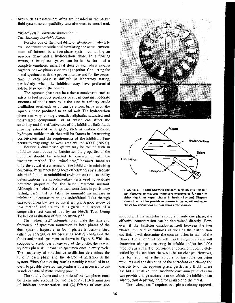
Oscillation\FIGURE 8 - (Top) Showing one configuration of a "wheel"test designed to evaluate inhibitors expected to function ineither liquid or vapor phases in both. (Bottom) Diagramshows how bottles provide exposures in water, oil and vaporphases for evaluations in these three environments.
products. If the inhibitor is soluble in only one phase, theeffective concentration can be determined directly. However, if the inhibitor distributes itself between the twophases, the relative volumes as well as the distributioncoefficient will determine the concentration in each of the
phases. The amount of corrodent in the aqueous phase willdetermine changes occurring in soluble and/or insolubleproducts as a result of corrosion. If corrosion is completelystifled by the inhibitor there will be no changes. However,the formation of either soluble or insoluble corrosion
products and the depletion of the corrodent can change thecorrosivity of the aqueous phase, particularly if this phasehas but a small volume. Insoluble corrosion products alsocan provide a large surface area on which the inhibitor canadsorb, thus depleting inhibitor available to the metal.
The "wheel test" requires two phases closely approxi-
36
tives such as bactericides often are included in the packerfluid system, so compatibility tests also must be considered.
"Wheel Test": Alternate Immersion in
Two Mutually Insoluble PhasesPossibly one of the most difficult situations in which to
evaluate inhibitors while still simulating the actual environment of interest is a two-phase system containing anaqueous phase and a hydrocarbon phase. In a flowingstream, a two-phase system can be in the form of acomplete emulsion, individual slugs of each phase movingtogether or two phases condensing together. Contacting themetal specimen with the proper mixture and for the propertime in each phase is difficult in laboratory testing,particularly when the inhibitor may have preferentialsolubility in one of the phases.
The aqueous phase can be either a condensate such asexists in fuel product pipelines or it can contain moderateamounts of solids such as is the case in refinery crudedistillation overheads or it can be strong brine as in theaqueous phase produced in an oil well. The hydrocarbonphase can vary among aromatic, aliphatic, saturated andunsaturated compounds, all of which can affect thesolubility and the effectiveness of the inhibitor. Both fluidsmay be saturated with gases, such as carbon dioxide,hydrogen sulfide or air that will be factors in determiningcorrosiveness and the requirements of the inhibitor. Temperatures may range between ambient and 400 F (205 C).
Because a dual phase system may be treated with aninhibitor continuously or batchwise, the properties of theinhibitor should be selected to correspond with thetreatment method. The "wheel test," however, measuresonly the actual effectiveness of the inhibitor in minimizingcorrosion. Persistency (long term effectiveness by a stronglyadsorbed film in an uninhibited environment) and solubilityde terminations are supplementary tests used to evaluatedesirable properties for the batch treatment method.Although the "wheel test" is used sometimes in persistencytesting, care must be taken to minimize an increase ininhibitor concentration in the uninhibited fluids throughcarryover from the treated metal sample. A good review ofthis method and its results is given in a report of acooperative test carried out by an NACE Task GroupT-1D-2 on evaluation of film persistency. 28
The "wheel test" attempts to simulate the time andfrequency of specimen immersion in both phases of thedual system. Exposure to both phases is accomplishedeither by rotating or by oscillating bottles containing thefluids and metal specimen as shown in Figure 8. With thecoupons or electrodes at one end of the bottle, the heavieraqueous phase will cover the specimen once in every cycle.The frequency of rotation or oscillation determines thetime in each phase and the degree of agitation in thesystem. When the rotating bottle assembly is installed in anoven to provide elevated temperatures, it is necessary to usevessels capable of withstanding pressure.
The total volume and the ratio of the two phases mustbe taken into account for two reasons: (1) Determinationof inhibitor concentration and (2) Effects of corrosion

Cooling Tower
FIGURE 9 - Diagram showing side stream technique forevaluation of inhibitors on heat transfer surfaces. Removable
tube can be weighed and examined to determine results.
uCondensate
=>'
Test Tube
used systems throughout industry, large and small. Thesystems are volumetrically static, in that a relativelyconstant volume of water is used. Since evaporation ofwater is used for cooling, losses must be made up from theavailable water source. Evaporation also causes a concentration of salts, the control of which requires removal ofsome water from the system. The surface-to-volume ratio isrelatively low in such systems so that little effect on the
bulk fluid can be expected from the corrosion process. Inmany cases, metals other than carbon steel are used for heat
exchanger tubing, including Admiralty brass, cupronickel,stainless steels and to some extent, aluminum and titanium.
The chapter on cooling water treatment elsewhere inthis book discusses many of the problems associated with
corrosion in these systems. Figure 9 shows one of several
ways to test the effectiveness of inhibitors in recirculatingcooling water systems.
Inhibitor Properties Other thanEffectiveness in Mitigating Corrosion
In many applications, properties of the inhibitor otherthan its effectiveness in inhibition are equally important inobtaining maximum efficiency with a minimum of un
desirable side effects. Some of these properties have beendiscussed in previous sections illustrating the importance ofsolubility, compatibility, potability and other characteristics in the four examples of inhibitor evaluation. In this
section, the properties listed in Table 2 will be discussed,showing their relationship to inhibitor effectiveness or theirundesirable side effects on the system. When known, amethod of evaluating the property of interest will bedescribed.
The properties of the "neat" inhibitor formulation
(Le., as received from the formulators) are importantmainly from the standpoint of handling the material. Lowviscosity is necessary to provide adequate pumping rates orflow rates. For example, when an oil well is treated
batchwise, the time to reach the bottom and the hangup onthe surfaces depends on viscosity which accordingly affectsthe shut-in period. Downtime costs money. Often, the
37
mating the actual environment of interest (the actual fluids,if possible) and a clean specimen of metal in the form of
coupons, Corrater electrodes or Corrosometer probes. Useof the Corrater or Corrosometer permits the use ofprerusted surfaces if these are necessary in the evaluation ofthe inhibitor. The inhibitor is added before the metal
contacts either phase and in some cases, the metal specimenis soaked for a short period in the inhibited hydrocarbonphase prior to alternate immersion. Quite often, the test isaccelerated by saturating the fluids with carbon dioxide orhydrogen sulfide, using a much higher concentration of theacid gases than is encountered in the field. While the use of
Corrater electrodes and Corrosometer probes in laboratorytesting is described in the literature, these sensing methodsare more useful under field conditions where rapid evaluation in the actual environment is desired rather than
laboratory testing under accelerated conditions.
NACE has committees continually reviewing testmethods for evaluation of inhibitors. Several methods for
evaluation of inhibitors in dual phase systems are presentedin the literature.2 8-30
Because of the wide variety of two-phase systems andbecause of the potential problems related to inhibitortreatment, other properties of the inhibitor formulationbecome quite important; each application will have itsspecific problems and requirements. Inhibitor solubility isan important factor and usually will be dictated by themajor phase present. In certain cases, such as in batchtreating oil wells, dispersibility of an oil-soluble inhibitorinto an aqueous phase is necessary merely to carry theinhibitor throughout the system. Dispersibility is alsonecessary for the same reason in using the relativelyinsoluble inhibitors for long-term persistency in batchwisetreatment.
The opposite effect (prevention of emulsion formation)is important in other applications where maximum separation of the phases is necessary. Emulsions can disruptrefining operations in which the residence time in separatingvessels is so short that there is carryover of each phase intothe other one. An extreme case is one in which the
emulsion is almost solid in consistency. A very mild form ofan emulsion, but perhaps even more intolerable than in anyother application is that of water retention in jet fuelswhereby small amounts of water can freeze and plug fuellines at extremely low temperatures. Foaming is just asdisruptive in refining operations as is emulsion formationand is prevalent where contact with gases or changes inpressure occur (See chapter on Refinery Inhibition).
In most applications involving dual phase systems,inhibition against corrosion is only one of the problems.Anti-scale inhibitors, bactericides or other additives may beadded along with the inhibitors. In such cases, supplementary tests must be carried out to determine their
mutual interaction. The different chemicals may be synergistic in their desired effects, but most likely they willinterfere with each other.
Recirculating Cooling Water Test
Cooling towers are probably one of the most widely
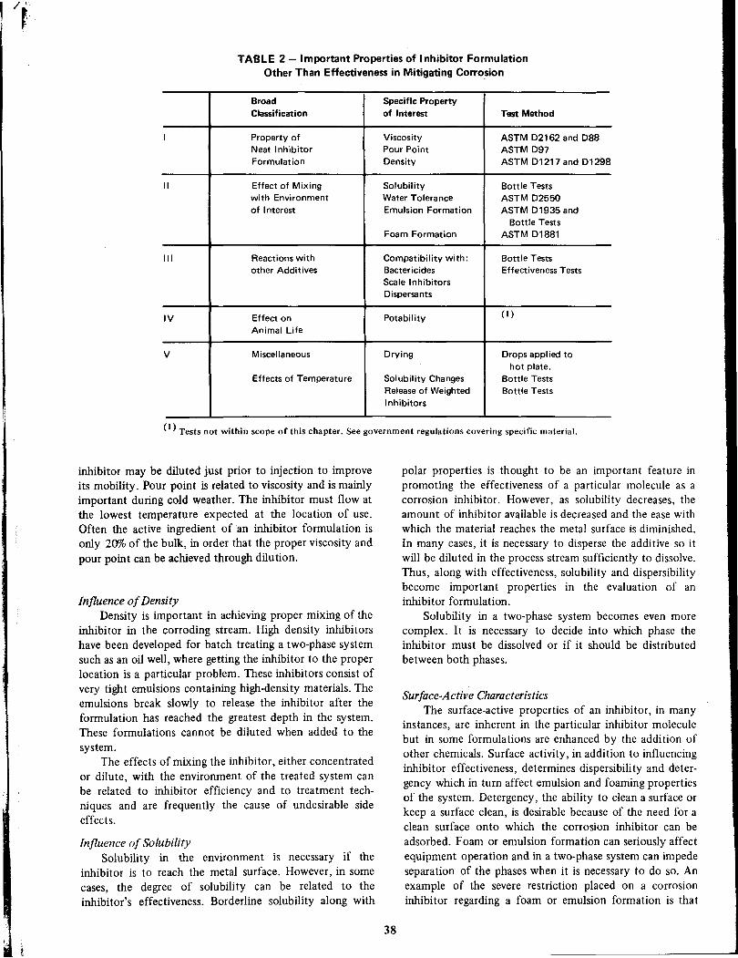
TABLE 2 - Important Properties of Inhibitor FormulationOther Than Effectiveness in Mitigating Corrosion
Broad Specific PropertyClassification
of InterestTest Method
I
Property ofViscosityASTM D2162 and D88Neat Inhibitor
Pour PointASTM D97Formulation
DensityASTM D1217and D1298
1I
Effect of MixingSolubilityBottle Testswith Environment
Water ToleranceASTM D2550of Interest
Emulsion FormationASTM D1935 andBottle TestsFoam Formation
ASTM D1881
III
Reactions withCompatibility with:Bottle Testsother Additives
BactericidesEffectiveness TestsScale Inhibitors Dispersants
IV
Effect on Potability(I)
Animal LifeV
MiscellaneousDryingDrops applied tohot plate.Effects of Temperature
Solubility ChangesBottle Tests
Release of Weighted
Bottle TestsInhibitors
(I) Tests not within scope of this chapter. See government regulations covering specific material.
inhibitor may be diluted just prior to injection to improveits mobility. Pour point is related to viscosity and is mainlyimportant during cold weather. The inhibitor must flow atthe lowest temperature expected at the location of use.Often the active ingredient of an inhibitor formulation isonly 20% of the bulk, in order that the proper viscosity and
pour point can be achieved through dilution.
Influence of DensityDensity is important in achieving proper mixing of the
inhibitor in the corroding stream. High density inhibitorshave been developed for batch treating a two-phase systemsuch as an oil well, where getting the inhibitor to the proper
location is a particular problem. These inhibitors consist ofvery tight emulsions containing high-density materials. Theemulsions break slowly to release the inhibitor after theformulation has reached the greatest depth in the system.These formulations cannot be diluted when added to the
system.The effects of mixing the inhibitor, either concentrated
or dilute, with the environment of the treated system canbe related to inhibitor efficiency and to treatment tech
niques and are frequently the cause of undesirable sideeffects.
Influence of Solubility
Solubility in the environment is necessary if theinhibitor is to reach the metal surface. However, in some
cases, the degree of solubility can be related to theinhibitor's effectiveness. Borderline solubility along with
38
polar properties is thought to be an important feature inpromoting the effectiveness of a particular molecule as acorrosion inhibitor. However, as solubility decreases, theamount of inhibitor available is decreased and the ease withwhich the material reaches the metal surface is diminished.
In many cases, it is necessary to disperse the additive so itwill be diluted in the process stream sufficiently to dissolve.Thus, along with effectiveness, solubility and dispersibilitybecome important properties in the evaluation of aninhibitor formulation.
Solubility in a two-phase system becomes even morecomplex. It is necessary to decide into which phase theinhibitor must be dissolved or if it should be distributed
between both phases.
Surface-Active CharacteristicsThe surface-active properties of an inhibitor, in many
instances, are inherent in the particular inhibitor moleculebut in some formulations are enhanced by the addition ofother chemicals. Surface activity, in addition to influencinginhibitor effectiveness, determines dispersibili ty and detergency which in turn affect emulsion and foaming propertiesof the system. Detergency, the ability to clean a surface orkeep a surface clean, is desirable because of the need for aclean surface onto which the corrosion inhibitor can be
adsorbed. Foam or emulsion formation can seriously affectequipment operation and in a two-phase system can impedeseparation of the phases when it is necessary to do so. Anexample of the severe restriction placed on a corrosioninhibitor regarding a foam or emulsion formation is that

concerning water tolerance of jet fuel. Water pickup in thefuel must be limited so that fuel lines will not freeze and
plug during low temperature operation. (See references inrefinery chapter.)
Testing for Solubility, Dispersibility, Emulsion FoamingSolubility, dispersibility and emulsion-forming proper
ties of an inhibitor can be determined in simple bottle tests.Either the actual fluids of interest or some closelysimulating them may be used. The inhibitor is added tobottles at varying concentrations and the bottles are shakenand then observed for total solubility or dispersibility andthe time for the dispersion to separate. If two-phasesystems are involved, both should be included in the bottleto find the effects of emulsion formation. For example, foroil field use, the bottle tests may include either high or lowmolecular weight hydrocarbons, aromatic or aliphatichydrocarbons, brine and mixtures of brine and hydrocarbons. (See also the effect of temperature at the end ofthis section.)
More elaborate equipment is required to determinecertain other properties. The ASTM D-2550 test describes amethod to determine water tolerance in jet fuels in whichthe fuel is emulsified, filtered, separated and the remainingentrained water is measured as turbidity by a photocell. Aless stringent test for water pickup is described in ASTM0-1935 where steam is sparged into the hydrocarbon phaseand time of cloudiness is measured. Detergency is difficultto evaluate in equipment other than that being treated. Inthe petroleum industry, detergency of fuels is evaluated insmall-scale engines.
Foaming occurs usually where gas evolution or pressurechanges occur. The ASTM D-1881 test describes a methodfor evaluating foaming characteristics in an automotiveantifreeze mixture in which a gas is bubbled at a fixed rate
through the fluid of interest and the height of the generatedfoam is measured. A similar test can be used for any single
fluid or mixed phase system.
Formation of Sludges or PrecipitatesThe use of corrosion inhibitors is often accompanied
by treatment with other additives such as scale inhibitors,dispersants, or bactericides. These additives may react withthe inhibitor to produce sludges or precipitates that have noprotective properties and which may consume the inhibitor,thereby reducing its concentration in the solution. Twokinds of tests should be carried out to determine the effects
of mixing if the chemical structure of each additive is notalready known. A bottle test should be carried out in whichrelatively concentrated solutions of the two additives aremixed and observed for gross reactions such as theformation of a precipitate. The second test is one in whicheach of the additives was originally evaluated. In this test,the additives are mixed at the low concentrations used in
treating and the test results of the mixture are comparedwith the results using the additive alone. If a significant lossof effectiveness is observed with the mixture, the materials
should be considered incompatible.
39
Ecological EffectsAlthough it is difficult to determine the effect of an
additive on the environment, it is necessary, nevertheless, tohave some information on this reaction. If the treated
system is to be ingested by human beings or animals, theadditives must have no toxicity. When disposal is to thesewer or to natural water streams, the effect on the
environment must be minimal. I t is beyond the scope ofthis book and of most people in the corrosion field toevaluate toxic effects, but suppliers of additives should havethe proper evaluations performed. It is also the responsibility of both the supplier and the user to be aware ofgovernment regulations regarding the use of specific chemicals in applications where potential pollution exists.
Effects of Temperature
The use of a corrosion inhibitor at elevated temperatures sometimes requires more tests than the evaluation ofinhibitor efficiency alone. Solubility may be affected in anunexpected way as the temperature increases. For example,some organic inhibitors have a lower solubility in brine atelevated temperatures than at ambient temperatures. In astatic system requiring relatively high concentrations of
FIGURE 10 - Showing autoclave used to test inhibitorsunder high temperature, pressure and velOCity conditions.Groups of specimens lright) are lowered into solutions lIeft)after solutions have been placed inside the autoclave. Atterpressures and temperatures are brought up, motors rotate thespecimens in the solutions. IFigure 3. Laboratory ApparatusTests Pressure and Velocity Effects on Corrosion of Oil FieldTubing in Inhibited Hydrochloric Acid. W. E. Billing, J. A.Knox and David Morris. Mat. Pro., 2, No. 8, 59-62 (1963)Aug.)

inhibitor (see description of packer fluid application), it isessential that the solubility of inhibitor be unaffected bytemperatures to which the solution is exposed. Bottle testscan easily evaluate these properties. Drying and theproperties of the resulting film can be important in hotgaseous systems where the carrier solvent will be evaporated. The film should flow at the temperature of thesystem, should not dry to form flakes which could beabrasive and should be readily soluble in some easilyavailable solvent. Simple tests can be devised to evaluatethese properties, e.g., by applying the neat inhibitor to ahot metal plate and observing the degree of evaporation,the degree of fluidity and the changes of the film withexposure time.
Figure 10 shows laboratory test equipment designed toevaluate inhibitors under heat, pressure and velocity conditions.
High density (weighted) inhibitors are designed toreach the bottom of oil wells by being heavier than oil orbrine phases in the well. Contact with brine at the elevatedtemperature at the bottom of the well causes the emulsioncarrying the inhibitor to break and release it to the system.It is of interest to know the time required for release of theweighted inhibitor or if it reaches the bottom of the wellbefore it is completely dispersed. A bottle test has beendevised in which the inhibitor is dropped through the hotbrine and the time for complete breakdown of the emulsionobserved. The characteristics of the released phase are alsonoted.
ASTM and NACE Test Methods
There are many test standards and recommendedpractices established by the American Society for Testingand Materials for corrosion testing or inhibitor evaluation.If a particular test is not available, variations of thoseincluded in the ASTM list often can be used to accomplishthe evaluation needed. A list of recommended practices andtest methods available from NACE and methods publishedannually by ASTM is given below.
NACE INHIBITOR TESTS1 K 155 - Proposed Standardized Laboratory Procedure for
Screening Corrosion Inhibitors for Oil and Gas Wells.1 K 160 - Proposed Standardized Static Laboratory Screening Test
for Materials to be Used as Inhibitors in Sour Oil and Gas Wells.TM-Ol-72 - NACE Standard Test Method, Anti-Rust Properties of
Petroleum Products Pipeline Cargoes.
INHIBITOR TEST METHODS DEVELOPEDby
American Society for Testing and Materials
Published annually, 1916 Race St., Philadelphia, Pa., 19103(Test Number is listed, followed by year of latest approval,with volume number in parenthesis).
Recommended PracticesG-I-67 (31) Preparing, Oeaning, and Evaluating Corrosion Test
Specimens.G3-68 (7,31) Conventions Applicable to Electrochemical Measure
ments in Corrosion Testing.
40
G4-68 (3,31) Conducting Plant Corrosion Tests.A262-68 (3) Detecting Susceptibility to Intergranular Attack in
Stainless Steels.
A393-63 (3) Conducting Acidified Copper Sulfate Test for Intergranular Attack in Austenitic Stainless Steel.
G5-69 (31) Standard Reference Method for Making Potentiostaticand Potentiodynamic Anodic Polarization Measurements.
G2-67 (7,31) Aqueous Corrosion Testing of Samples of Zirconiumand Zirconium Alloys.
Standard Methods of TestA279-63 (3) Total Immersion Corrosion Test of Stainless Steel.B380-65 (7) Corrosion Testing of Decorative Chromium Plating by
the Corrokote Procedure.
D665-68 (17) Rust-Preventing Characteristics of Steam-Turbine Oilin the Presence of Water.
D1743-68 (17) Rust Preventive Properties of Lubricating Grease.B117-64 (7,21) Salt Spray (Fog) Testing.B287-68 (7,21) Acetic Acid-Salt Spray (Fog) Testing.B368-68 (7,21) Copper-Accelerated Acetic Acid-Salt Spray (Fog)
Testing.D2059-63 (25) Resistance of Zippers to Salt Fog Test.D1748-62T (17) Rust Protection by Metal Preservatives in the
Humidity Cabinet.D2688-69 (23) Corrosivity of Water in the Absence of Heat Transfer
(Weight-Loss Method).D2776-69T (23) Corrosivity of Water in the Absence of Heat
Transfer (Electrical Methods).D807-65 (23) Corrosivity of Industrial Water (USBM Embrittlement
Detector).01384-65 (22) Corrosion Test for Engine Antifreezes in Glassware.02570-66T (22) Simulated Service Corrosion Testing of Engine
Antifreezes.
01616-68 (20) Copper Corrosion by Mineral Spirits (Copper StripTest).
0130-68 (17) Copper Corrosion by Petroleum Products (CopperStrip Test).
0849-66 (20) Copper Corrosion of Industrial Aromatic Hydrocarbons.
01838-68 (18,19) Copper Strip Corrosion by Liquefied Pctroleum(LP) Gases.
01261-68 (17) Effect of Grease on Copper.02649-67T (18) Corrosion Characteristics of Ory Solid Film
Lubricants.
C464-64 (14) Corrosion Effect of Thermal Insulating Cements onBase Metal.
01611-60 (15) Corrosion Produced by Leather in Contact withMetal.
F64-69 (28) Corrosive and Adhesive Effects of Gasket Matcrials onMetal Surfaces.
01275-67 (18,29) Corrosive Sulfur in Electrical Insulating Oils.01567-68 (22) Oetergent Oeaners for Evaluation of Corrosive
Effects on Certain Porcelain Enamels.
02251-67 (22) Metal Corrosion by Halogenated Organic Solventsand Their Admixtures.
01374-65 (22) Aerated Total Immersion Corrosion Test for MetalCleaners.
01280-67 (22) Total Immersion Coupon Test for Soak Tank MetalCleaners.
0930-67 (22) Total Immersion Corrosion Test for Water SolubleAluminum Cleaners.
References1. F. A. Champion. Corrosion Testing Procedures. John Wiley &
Sons, New York, N. Y. (1952).2. M. G. Fontana and N. O. Greene. Corrosion Engineering, p.
116, McGraw-Hill Book Co., New York, N. Y. (1967).3. ASTM G-1. Recommendcd Practice for Preparing, Cleaning and
Evaluating Corrosion Test Specimens. Book, Vo!. 7, AmericanSociety for Testing and Materials, Philadelphia, Pa. 19103.

4. NACE Publication 3D 170, National Association of CorrosionEngineers, 2400 West Loop South, Houston, Texas 77027.
5. A. C. Nestle. Corrosion Monitoring Method Reduces Effect ofVariables in Analyzing Oilfield Waters, Materials Protection, 8,49 (1969) May.
6. A. W. Coulter and C. M. Smithey. Rapid Screening TestDeveloped to Find Hydrochloric Acid Inhibitors for HighTemperature Service, Materials Protection, 8,37 (1969) March.
7. G. A. Marsh. Some Notes on Hydrogen Blistering, Corrosion,10,101 (1954).
8. F. J. Radd and D. H. Oertle. Getter Ion Probe Studies of
Hydrogen Entry into Iron from Liquid and Gaseous AmmoniaSystems. Presented at the National NACE Meeting, Chicago,111.,March, 1971.
9. E. H. Phelps. Electrochemical Techniques for Measurement andInterpretation of Corrosion, Corrosion, 18, 239t (1962).
10. N. Hackerman. Recent Advances in Understanding of OrganicInhibitors, Corrosion, 18, 332t (1962).
11. W. H. Chapman. Testing Corrosion Inhibitors, Materials Protection, 5, 12 (1966) March.
12. J. Kruger. Use of Ellipsometry in the Study of Corrosion,Corrosion, 22, 88 (1966).
13. B. J. Bornong and P. Martin, Jr. Ellipsometric-PotentiostaticStudies of Steel Corrosion Oxide Film Development and Effectof Inhibitors, Corrosion, 27,315 (1971) August.
14. B. Dus and Z. Szklarska-Smialowska. Double Layer CapacitanceMeasurements of Inhibitive Properties in HCI of Some Phosphoorganic Compounds, Corrosion, 25,69 (1969).
IS. B. Mosier and G. B. Farquhar. Use of Differential CapacitanceMeasurements to Predict the Inhibitive Behavior of OrganicNitrogen Compounds, Corrosion, 23,349 (1967).
16. P. F. Cox, R. L. Every, and O. L. Riggs, Jr. Study of AromaticAmine Inhibitors by Nuclear Magnetic Resonance, Corrosion,20, 299 (1964).
17. W. B. Hughes. A Copper Ion Displacement Test for ScreeningCorrosion Inhibitors, Journal of Petro. Tech., 54 (1958)January.
41
18. 1. A. Knox and R. Stout. Determination of Inhibitor FilmPersistency. Corrosion, 15, 544t (1959) October.
19. R. F. Overman. Using Radioactive Traces to Study ChlorideStress Corrosion Cracking of Stainless Steels, Corrosion, 22,48(1966).
20. R. R. Annand and M. J. Michnick. Tracer Experiments DuringBatch Treatment of Gas Wells with Corrosion Inhibitors,Materials Protection, 10,41 (1971) August.
21. C. C. Patton and B. M. Casad. Tests Determine Effect ofOrganic Inhibitors on Corrosion Fatigue, Materials Protection,8,56 (1969) September.
22. B. R. Keeney, R. M. Lasater, and J. A. Knox. New OrganicInhibitor Retards Sulfide Stress Cracking, Materials Protection,7, 23 (1968) April.
23. ASTM D807. Standard Method of Test for Industrial Water
(USBM Embrittlement Detector Method). Book, Vo!. 23,American Society for Testing and Materials, Philadelphia, Pa.19103.
24. R. A. Legault, S. Mori, and H. P. Leckie. An ElectrochemicalStatistical Study of the Effect of Chemical Environment on theCorrosion Behavior of Mild Steel, Corrosion, 26, 170 (1970).
25. C. C. Nathan and D. L. Dulaney. How Statistical ConceptsFacilitate Evaluation of Corrosion Inhibitors, Corrosion, 10, 21(1971).
26. S. A. Bradford. Corrosion Failure Expectancy -A CriticalExamination, Materials Protection, 9, 13 (1970) July.
27. L. C. Rowe. An Evaluation of Inhibitors for Corrosion
Prevention in an Engine Cooling System, Corrosion, 13, 750t(1957) November.
28. NACE T-ID-2 Task Group Report. Cooperative Evaluation ofInhibitor Film Persistency Test, Materials Protection,S, 69(1966) "October.
29. NACE T-IK Report. Proposed Standardized Laboratory Procedure for Screening Corrosion Inhibitors for Use in Oil and GasWells, Corrosion, 11, 143t (1955) March.
30. NACE T-IK Report. A Proposed Standardized Static Laboratory Screening Test for Materials to be Used as Inhibitors in
Sour Oil and Gas Wells, Corrosion, 16, 63t (1960) February.

C. C. NATHAN*
Corrosion Inhibitors in Refineries and PetroChemical Plants - Part 1
Bregman's 1963 edition of "Corrosion Inhibitors" devotesover thirty pages to problems of refinery corrosion andtheir solutions. The material is extensively referenced,
covering the technology since the beginning of the refiningindustry in both the United States and in Europe. Causes ofrefinery corrosion and solutions of corrosion problems bymetallurgical methods and by use of chemical inhibitors aregiven. Because most of Bregman's information is stillapplicable in today's plants, it will be summarized briefly inthis chapter which will primarily update the earlier work byreferences to literature of the past ten years. Specialemphasis will be given to topics such as the use of chemicalantifoulant agents, corrosion in gas processing plants and inhydrotreating operations because these topics have recentlybecome of increasing interest and importance in refiningand petrochemical processing. Solution of corrosionproblems by metallurigical approaches will be consideredonly slightly and greatest emphasis will be placed on the useof chemical inhibitors.
General ConceptsCorrosion in the hydrocarbon processing industries
may be conveniently divided into two types: "wet" and"dry". "Wet corrosion is that which occurs in presence ofliquid water. Corrosion in the absence of water isconsidered "dry". Wet corrosion normally implies lowtemperatures, Le., below the boiling point or dew point ofwater. This temperature will, of course, be a function of thesystem pressure as well as its composition. In practice, wetcorrosion is limited to about 450 F (232 C) as an uppertemperature. The lower temperature is set by fluidcomposition. For wet corrosion to occur at anytemperature there must exist either a discrete aqueousphase or sufficient water dissolved in a liquid phase toimpart electrical conducting or ionic properties to a liquidsuch as hydrocarbon, which does not possess these properties in the absence of water. Wet corrosion is an
electrochemical process, so concepts developed in otherchapters of this book, (Coqling Water, Petroleum Production, Water Flooding) are equally applicable. Wet corrosionmay be controlled by the use of passivating, neutralizing oradsorption type inhibitors, the use of which will bediscussed in detail in this chapter from theoretical, practicaland economic aspects.
*Betz Laboratories, Inc., Philadelphia, Pa.
42
Dry corrosion is of great importance in a number ofrefining processes. It includes the attack of hydrogensulfide and other sulfur compounds on steel and variousalloys at elevated temperatures (as distinguished from theattack of aqueous solutions of hydrogen sulfide andmercaptans). Solutions to this type of corrosion generallydepend on metallurgical approaches, such as variations incomposition and/or heat treatment of the selected metal oralloy. A partial list of recent articles supplementing thediscussion is given in References 1-12.
Other important examples of dry corrosion in refiningand petrochemical processes include attack by hightemperature combustion atmospheres on metal tubesconducting feed and products in cracking furnaces. Anotherexample is hydrogen attack at elevated temperatures andpressures such as encountered in hydrogenation or reforming operations in the production of synthesis gases bypartial oxidation of hydrocarbons. Because of the ex tremesof pressure and temperature involved, these problems arevery serious and their solution is costly. The solutionsdepend on metallurgical and design factors, some of whichare discussed in References 1-12. Corrosion inhibitors do
not offer solutions for such problems as high-temperatureoxidation, decarbonization, iron "dusting" and high temperature sulfur corrosion. Accordingly, these problems willnot be discussed further in this work.
Nature of Corrosive Fluids
Since the discussion of refinery and petrochemicalplant corrosion inhibiton will be restricted to attack takingplace in the presence of aqueous fluids, the composition ofthese· fluids is of interest insofar as their compositionaffects corrosion and its inhibition. Only fluids on theprocess side of equipment need be considered. As anexample, a heat exchanger in which naphtha vapors in theshell are being condensed by cooling water in the tubes mayexperience corrosion on both shell and tube side. Corrosion
by cooling water and attendant scaling and fouling problems are of great importance; however, the factors involvedin the corrosion and its solution are generally the same asthose covered in the section on cooling water and need notbe further considered in this chapter. Similarly, refineriesand petrochemical plants generally produce large quantitiesof steam both for primary power and other needs and in
waste heat steam generators. The I?roblems and treatment

of boiler feedwater and condensate are covered in the
chapter on boiler water corrosion inhibition.Generalizations concerning cooling water, boiler water,
etc. are subject to exceptions when various refinerywaste-water streams are used as boiler feed, desalter feeds,etc. in order to reduce demands for fresh or makeup waterto the boilers and cooling systems and/or to prevent
pollution of natural streams by refinery effluents. Thisproblem is becoming increasingly important with thegrowing interest in pollution prevention and control.
A further problem which may be encountered whenusing corrosion inhibitors, scale preventives, biocides, etc.,in either the process or cooling water side of the plant isthat of process equipment failure and the effect of onestream's leaking into the other. As an example, a smallleakage from a process stream containing hydrogen sulfidecan be very deleterious to a cooling water treatmentprogram using a chromate-based inhibitor. Reduction ofchromate not only makes a corrosion control programineffective but also may result in formation of harmfulsludges and scales on water-side equipment.
Restricting the discussion to process streams with anaqueous phase present, such streams may be considered asbeing composed of:
1. An aqueous phase,2. A hydrocarbon or non-aqueous liquid phase, and3. A gas phase.
The liquids and gas phases will be in dynamic equilibrium atall points in the system, the equilibria being determined bypressure, temperature and composition. It will be useful toexamine the general concepts of equilibria and composition:
Gas Phase
The gas phase consists of hydrocarbons vaporized bydistillation processes and/or formed by cracking or otherdecomposition of fluids. Sulfur compounds such as hydrogen sulfide and volatile mercaptans often present in the gasphase may be components of the original feed to the unitof interest, e.g., the crude still; they may be formed bythermal degradation of disulfides, thiophenes, etc., or theymay be the result of various hydrogenation processes suchashydrodesulfurizing, hydrocracking, etc.
Similarly, nitrogen compounds may be present in thefeed stock or result from thermal decomposition orhydrogenation of nitrogenous compounds to ammonia
.. and/or hydrocyanic acid. Oxygen compounds, such as fattyor naphthenic acids, occur in some crudes. Both carbondioxide and carbon monoxide are formed during variousreforming reactions as well as in the regeneration bycombustion and/or steaming of catalysts. Free oxygen maybe present due to leakage of air into the system, particularyin equipment at moderate pressure, when centrifugal pumpsare used. Air leakage also can occur when intermediate or
product streams are stored at atmospheric pressure beforefmal processing.
Prevention of air-leakage or other contamination is
highly desirable and is effected by proper equipment
43
maintenance, inert gas blanketing, etc. Prevention is rarelyone hundred percent effective in the practical sense. Thislimitation will be discussed further in the section on
fouling.
Liquid Hydrocarbon Phase
This phase will be in dynamic equilibrium under theconditions of temperature, pressure, etc. with the vaporphase described above as well as with the water phasecontacting it. In this connection, it is of interest that thesolubility of hydrogen sulfide and carbon dioxide inhydrocarbons is generally large as compared to that ofoxygen and nitrogen. Furthermore, hydrogen sulfide generally has higher solubility in hydrocarbons than in water,while the reverse is true of oxygen, carbon dioxide,ammonia, etc.
Liquid Aqueous PhaseBecause electrochemical corrosion reactions proceed
only in a liquid aqueous phase, the chemical composition andproperties determined by chemical composition of thisphase are most important to consider. This phase is largelywater and will be called water in the subsequent discussion.Water enters the various refinery process units in a numberof ways. Of prime importance is water which is entrainedand/or emulsified in the crude oil charge to the refinery,Le., feed to the crude still. This water is produced withcrude oil and remains with the crude, despite oil-fieldseparators, liquid traps in pipelines, etc. Although theamount of water is usually small in total volume, its effecton corrosion may be large, since it usually contains a highproportion of corrosive dissolved salts, mainly chlorides ofsodium, calcium and magnesium.
A second source of water is through injection of wateror steam to aid in the steam distillation of various
petroleum fractions. Condensation of overhead vapors ofboth steam and hydrocarbon results in separation of awater layer from the hydrocarbon product. This layerprobably will be reused in the refinery. The condensedaqueous phase contains various corrosives which attackdistillation and condensation equipment and which will bediscussed in detail in a later section.
A third important source of water is water-washing oraqueous solution contacting various intermediate and product streams in refining and petrochemical processes. Thisincludes the use of various extraction processes such asfurfural in production of lubricants, acetonitrile for butadiene purification, ethanolamines in gas purification, etc.All use an aqueous solution of the extractant.
The aqueous phase always will be dynamic equilibriumwith the other fluids it contacts. Because of its property asa "universal solvent", the water phase usually contains awide variety of dissolved liquids, gases and solids, bothorganic and inorganic. Dissolved materials in the wateressentially determine its corrosivity to plant equipment.Probably the most important property of the water phasefrom the corrosion standpoint is pH. With some exceptions,most industrial corrosion in refineries and elsewhere is acid
corrosion, that is, attack at low pH on active metals such as

iron, copper, zinc, aluminum and their alloys. Ordinarystructural steel may be considered to have the samecorrosion-resistant properties as iron in acid media, so thetwo terms will be used interchangeably. Also, since the bulkof industrial process equipment is steel, the corrosionproperties of steel are of greatest interest and unlessotherwise specified in the subsequent discussion of attackon process equipment, steel will be implied.
Corrosion of SteelSteel is very unstable in acids, as might be expected
from the position of iron in the electromotive force series.In the absence of inhibitors, corrosion rates increase sharplyas pH falls below neutrality. At pH values above seven, steelis generally stable with increasing pH, up to values as highas 13 or greater. (At higher pH's, particularly at elevatedtemperatures, attack results because of the weakly amphoteric properties or iron.) From the practical standpoint,neutralization of acid solutions to pH 6-8 normally isadequate to stifle direct attack on steel; however, whenneutralization is augmented by inhibitors, adequate corrosion protection can be effected at pH values between 5 and6. (The discussion above refers to reducing or oxygen freesystems, which refmery process streams usually are.)
Acidity is imparted to refinery fluids by solution in thewater phase of various acid gases such as hydrogen sulfide,hydrocyanic acid, carbon dioxide; by organic fatty andnaphthenic acids, as described in detail by Bregman; and bymineral acids, chiefly hydrochloric acid. Hydrochloric acidis formed in refmery operations by thermal decompostionand hydrolysis of magnesium and calcium chlorides notremoved in desalting operations. It also may appear as aconstituent or by-product in various petrochemical processes of chlorination and alkylation. In general, acid attackincreases with the quantity of total dissolved acid orinversely as the pH of the environment; however, there areimportant exceptions, and weak acids such as hydrocyanic,hydrogen sulfide and carbon dioxide are more corrosive tosteel than would be expected from the pH-corrosivitygeneralization discussed above.
There are also important exceptions, such as inhydrocracking and in ethanolamine units, where steel maycorrode at high pH. In these cases the normally protectiveiron sulfide or oxide film is destroyed, presumably bycomplexing of the iron with nitrogen compounds such ascyanides fromed by hydrogenation of crude or by breakdown products of ethanolamines.
Corrosion of Copper AlloysAfter steel, probably the most important metal in
refinery use at low (i.e. less than furnace) temperature iscopper, usually in the form of such alloys as CopperDevelopment Association alloys No. 443445 (Admiralty)or CDA 715 (MoneI) etc. In addition to higher heatconductivity, copper and its alloys are considered to besuperior in corrosion resistance to steel in media such asdilute acids, saline and brackish waters and in the presenceof sulfur compounds. Because copper and its alloys havelower strength and versatility and cost more than low
44
carbon steels, substitution of steel by copper alloys must bejustified in materials savings and/or process improvement.
Although copper is generally more resistant to acid refinerystreams than is steel, the effect of pH on corrosion ofcopper is more involved than on steel. Close pH control isnecessary because of the dissolution of copper and its alloysat elevated pH under some conditions. At low pH,secondary factors such as presence of oxygen and fluidvelocity are quite important in the corrosion of copper. Athigh pH, in the presence of ammonia and some amines,soluble copper complexes form which effect copper dissolution. Special precautions are required as described below.
Neutralizing Corrosion InhibitorsBecause corrosion is known to result from acid attack
on metals, the removal or neutralization of acids is an
obvious solution to the corrosion problem. In theory, anymaterial sufficiently basic to neutralize the acid and raisepH to the desired level should be satisfactory. In practice,the situation is complicated by other factors.
This is illustrated by operation of the desalter, which isusually the first processing unit in the refinery proper. Itsfunction is to redlJce the content of bottom sediment and
water (B.S.&W.) from the crude charge to the crude still. Asexplained above, water (generally brine) causes corrosion inunits downstream of the desalter as a result of decomposition of chlorides to hydrochloric acid at the elevatedprocessing temperatures. Addition of alkali to the desalterwas shown by Samuelson1 3 to reduce hydrolysis of calciumand magnesium chloride and consequently result in lesshydrocWoric acid being formed in the crude still overheads,etc.
Inexpensive neutralizers such as lime, calcium carbonate and soda ash often may cause scaling problems due toprecipitation of insoluble hydroxides and/or carbonates ofMg and Ca by reaction with these ions in water entrainedfrom the desalter. Bregm an describes a number of neutralizing materials which have been used in the past with varyingsuccess. Sodium hydroxide is still used in desalting, forwhich it is added in amounts approximating the chloridecontent of the desalter water.
Some plants today are attempting to establish alkalinity in the desalter by using high pH boiler blowdown asdesalter feed. Others use high pH effluents from sour waterstrippers.14 The dangers of this practice as described in arecent National Petroleum Refiner's Association panel,lsinvolve the problems of scale formation of Mg and Ca saltsat high pH and foaming at high alkalinity and/or in thepresence of surfactants. This foaming causes poor waterdrawoff from the desalter, etc. A good summary of moderndesalter practice and the effects of de salting operationvariables on subsequent crude still corrosion and fouling isgiven by Fisher, et al. I 6
The first operating unit in a refinery after the desalteris the crude still, which effects a rough separation byboiling range of several refinery streams such as naphtha,kerosene, diesel oil, etc. Distilled vapors are condensed atone or more points and products are taken off with desiredreflux ratios, etc. The condensed liquids may contain

45
copper forms the soluble cuprammonium complex anddeterioration of such materials as CDA 443-445 (Admiralty) can be expected. Similarly, some of the low
molecular amines also can form soluble copper complexes.Control of pH is not an unusual industrial operation and
can be effected with automated measuring, recording andfeeding equipment now available. The expense of suchequipment can often be justified to plant management bysavings in chemicals injected and in increased efficiency ofcorrosion control. Alternative approaches to such close pHcon trol are discussed in Reference 19.
An additional drawback to the use of ammonia is the
formation of ammonium chloride deposits, which causefouling problems, resulting in reduced flow-rates and heattransfer. Intermittent or preferably continuous water washing can remove the deposits. The problem is described in a
number of industrial case histories including that byCarlton.17
Carlton's article, as does that of Backenstol8, pointsou t an additional complication-corrosion of base metalunder the deposits. Carlton also discusses how this corro
sion can take place in the absence of an aqueous liquidphase, an unusual occurrence under refinery conditions. Arecent article by Nathan19 describes the development anduse of higher molecular weight amines, which do not formchloride deposits from either the hydrocarbon or water
phase and which also have good buffering capacity compared to ammonia and morpholine. Such material permitseasier pH control and largely eliminates the danger ofcopper corrosion at high pH (above 7.5 in presence ofammonia or amines). This is shown in Figure I.
Filming Inhibitors
Refineries and petrochemical processes employ a variety of film forming inhibitors under varying conditions.Bregman describes a number of inhibitors and others havebeen developed in the past ten years.
The mechanism by which all materials function is the
same and requires their adsorption onto the metal throughtheir polar group or head. The nonpolar tail of the inhibitor
molecule is oriented in a direction generally vertical to themetal surface. It is believed that the hydrocarbon tails mesh
with each other in a sort of "zipper" effect to form a tightfilm which repels aqueous fluids, establishing a barrier tothe chemical and electrochemical attack of the fluids on the
base metal. A secondary effect is the physical sorption ofhydrocarbon molecules froin·· the process fluids by thehydrocarbon tails of the adsorbed inhibitor molecules. Thisincreases both the thickness and effectiveness of thehydrophobic barrier to corrosion.
Based on the above explanation, it may be understoodwhy such inhibitors are generally more effective in thepresence of an oil phase. In fact, it is often difficult to use
filming inhibitors effectively and economically in theabsence of an oil phase. Selection of the proper inhibitorfor a specific application is generally a practical rather thana theoretical problem. Inhibitors are available with a wide
range of solubilities and other physical properties. Theconcentrations at which they are used generally is about ten
200016001200
ppm Hel Titrated
800
/'/'///
III
IIII
II
//
/""-/ Intermediate
// Molecular Weight
/ Oil-Soluble Neutralizing/ Amine///////
//
//
I/
/////'/,,/'
400
80
70
9.0
60
5.0
4.0
30
2.0
FIGURE 1 - Crude unit-atmosphere tower overhead water.(Betz Laboratories)
dissolved acidic components such as hydrochloric acid andhydrogen sulfide and will be corrosive to metals contacted
by the liquids. Corrosion may be expected as soon as thedew point of the water is reached, so treatment chemicals
must be added at or up-stream of the points of initialcondensation. Although various neutralizers were usedformerly, modern practice for overhead streams has beenessentially limited to ammonia and other low-molecular
weight amines such as morpholine or cyclohexylaminewhich are added either as undiluted liquids or vapors or asaqueous solutions.
Ammonia is the most common material because of its
high neutralizing power, low unit cost, easy availability andconvenience of handling. It may be injected as a liquidunder cylinder pressure and flashed into the vapor phase ofthe crude still. Upon condensation of the vapors, ammoniawill dissolve into the condensate water to effect an increasein its pH. As additional water condenses downstream of the
initial point, it will be in equilibrium with ammonia gas inthe condensing hydrocarbon and water vapors.
Despite the advantages mentioned above, using ammonia has several drawbacks .. Addition of ammonia beyondneutralization, i,e,. pH to >7 is a dangerous practice ifcopper alloys are present in the condensing system ordownstream of it in the water drawoff. At pH values in
excess of 7.0 to 8.5 (depending on the source quoted),

parts per million (ppm) based on the hydrocarbon phase, sothe economics is generally quite favorable.
Although many polar types of inhibitors are describedin the literature, those most widely used in petroleumrefining contain nitrogen bases such as amines, diamines,imadazolines, pyrimidines and their salts or complexes withfatty acids, naphthenic acids and sulfonates. Inhibitors varyin solubility, etc., as mentioned above and also must bechosen in consonance with pH range and other fluidproperties.
In general, it is more economical to reduce all or aportion of the acid content of treated stream with ammoniaor other neu tralizer and augment this by use of afilm-forming inhibitor. As an example, five ppm of afilming inhibitor applied at pH of 5.5 is often an effectiveand economical treatment. At lower pH, several times asmuch inhibitor would be required, while at higher pH, theproblems of ammonium chloride deposits would have to beconsidered. Specific applications are given in the casehistories of various units.2 0
Film-forming inhibitors, as distinguished from ammonia and other volatile amines, are considered to benonvolatile; accordingly, in any gas-liquid separation process, they remain with the liquid and so may be concentrated in the heavy fractions of a refinery process. Thismeans that the inhibitors must be injected by suitable
equipment at the point of use. If another corrosionproblem occurs at a down-stream unit, it may be necessaryto inject additional inhibitor to protect the second unit.The efficacy of an inhibitor treatment or other processchanges in controlling corrosion is easily followed inrefinery work by use of corrosion test coupons or spools,corrosion rate meters, corrosion resistance probes and byanalysis of process streams for dissolved metal. While thesemethods are explained in more detail in this book in thechapter on Corrosion Measurements, a few general conceptsapplied to refineries will be given here.
Methods of Measurement
Irrespective of the method, it should be rememberedthat the relative corrosion rate before and after treatment is
used as a basis of comparison. This is generally easier todetermine and of more use than the absolute rate. It is also
important to consider that the build-up, breakdown andrepair of films formed by adsorption-type inhibitors are notinstantaneous processes but may require times of the orderof several days. Accordingly, the limitations of spotreadings as determined by electrical corrosion rate metersand "grab" samples of fluids for metal ion analysis must beconsidered. In addition, because a corrosion rate metergives readings only in electrically conducting media, readings are dependent on the conductivity of the medium andsuitable corrections must be made for stream compositionand/ or conductivity.
Process stream analyses for dissolved metals such asFe2+, Cu2+ among others, can be carried out quickly andcheaply, but are of questionable value in streams containing
hydrogen sulfide, because its corrosion products usuallywill be insoluble sulfide~.
46
Obtaining a representative and reliable sample of thestream is difficult under such conditions. In addition,because of their detergent action, many inhibitors oftencause an initial increase in the amount of sludges and scalegoing into the process stream as old deposits are loosenedby the detergent-inhibitor and slough off equipment. Thisincrease must be recognized for what it is and not beassumed to signify an increased corrosion rate.
Test CouponsTest coupons are the most widely used tool in
monitoring refinery corrosion and its treatment becausethey may be easily prepared, inserted, removed andevaluated. Coupons are composed of metals similar to thoseof interest and exposed to conditions similar to those ofinterest. An exception is that "clean" coupons withreproducible surface characteristics are always used, whilethe surfaces being corroded are frequently dirty, scaled, orroughened in a manner difficult to categorize or reproduce.For this reason, corrosion rates on coupons often are highinitially but drop off with time to a steady-state value asthe coupon surface approaches the condition of the actualplant equipment surface. A fresh coupon placed in aninhibited system also will show a high corrosion rateinitially until the inhibitor film has had time to build up onthe coupon surface.
Accordingly, coupon exposure times are generally 2 to4 weeks for determination of "before" and "after" con
ditions. Exposure time will be limited and data questionable if process changes are made during the exposureperiod. Such variations as changes in feed stocks, processingcharge rates, temperatures and the like may affect corrosionrates sufficiently to negate the effects caused by changes inthe inhibitor program under investigation.
Application Equipment
The practical aspects of equipment used in inhibitor injection cannot be neglected. As previously emphasized, the inhibitor cannot be effective unless it is in
intimate contact with the metal surface being attacked atthe desired concentration and at the point(s) of attack.Because of the very small concentrations of inhibitor
required, even streams of thousands of barrels per dayrequire but a few gallons of inhibitor. The material, diluted
with a suitable solvent, is injected into the stream at desiredlocations by a small chemical injector pump which canovercome the pressure of the operating unit. However,usually it is convenient to dilute the inhibitor with the
product stream into which it is being injected. An adequatepump can be used, or a side stream from the operating unitis employed. Also, the larger the volume of inhibitorsolution injected, the better its mixing efficiency in theprocess stream and the more uniform the treatment is.
Special equipment such as "quills" also are obtainablefor injection of the inhibitor as fine droplets or mist into agas stream and for effecting more uniform distribution. Thisis necessary when it is desired to treat a gas rather than aliquid. In recent years the trend has been to purchaseinhibitors in tank truck quantities. The inhibitors are put

effective levels. Nathan21 discusses the problem in somedetail
If iron content is used to measure results of inhibitor
treatment, the initial rise when treatment is begun, usuallyattributable to cleaning of scaled surfaces, will soon fall to arate less than that before treatment. If it does not, theneither too little inhibitor is being used, or the inhibitor isnot being added in such a way that it reaches the corrodingequipment.
In actual plant practice, the inhibitor is normally addedat concentrations of 5 to 10 times the final desired
recommended value.(2) The high concentration reduces thetime needed for sloughing of old deposits and alsoaccelerates the attainment of a good film on the cleanedmetal. The concentration is gradually reduced after this,until the desired inhibition level (as shown by coupons,resistance probes, water analyses) is attained at an economical cost.
Surfactant Properties of Inhibitors
The effectiveness of film-forming inhibitors, as alreadystated, depends upon strong adsorption of inhibitor mole
cules at the interface between the process liquid(s) and themetal surface to be protected. It is not at all unusual formaterials active at a solid-liquid interface to be active alsoat a liquid-liquid and/or liquid/gas interface. The formermay cause emulsification problems, the latter may result infoaming. (Foaming problems will be discussed in a later
section on corrosion in gas processing units.) Emulsionproblems are evidenced in water drawoffs in retlneryequipment and in petrochemical plants, e.g., separation ofoils and tars from ethylene quench water systems.
Of great importance when refining products such as jetfuels is emulsification of small quantities of water in to theproduct. The water may enter the system because ofstorage tanks which "breathe" humid atmospheres or carrywater bottoms or by contamination or careless handling.Water that does get into the jet fuel storage system often isdifficult to remove with settlers or coalescers when surfac
tants are present in the system.Because of the deleterious action of emulsified water in
promoting bacterial growths in storage and in freezing andclogging of fuel injection nozzles during operation, jet fuelpurchasers have strict requirements concerning such wateras well as fuel response to it. This is usually determined bythe ASTM Water Separometer Index, Modified or WSIMTest. 22 Essen tially the test correla tes the presence ofemulsified and/or entrained water droplets injet fuels withturbidity of fuel measured under closely controlled andstandardized conditions. The effect of various surfactants
such as corrosion inhibitors can be determined by this test.No generalizations can be given abou t the effect of a given
dosage le 1\
B
time
A
time
(2)Start-up Programs
A - If dirty.B - If cleaned.
47
into bulk storage tanks before use. This practice offers theadvantages of savings from quantity buying and reduceslabor costs for inhibitor storage, dilution and handling.
Other recent innovations include formulation of neu
tralizing and film-forming inhibitors in a single drum ortank and the combination of inhibitors and antifoulants.
Antifoulants are discussed in a later section. Again, the
purpose is to simplify treating programs by reducing costsof lab or, storage facilities and handling.
(I )See the discussion on antifouJants in Part 2 of this chapter.
Special Concepts in Useof Corrosion Inhibitors to Refineries
Film-forming and/or neutralizing inhibitors in refineriesoffer no panaceas. Chemical treatment for prevention ofcorrosion is one of several tools used by competentengineering and management personnel as approaches tocorrosion control alternative to other measures such as
special resistant materials, protective coatings, designchanges and the like. Before discussing the relative advantages and disadvantages of the various protective andcorrective measures, some limitations, as well as pitfalls toavoid in using inhibitors will be mentioned.
Temperature LimitationsFilm-forming inhibitors contain organic molecules with
carbon-carbon, carbon-hydrogen, carbon-nitrogen bondsand so on. In common with other organic molecules, they
decompose at elevated temperatures. It was pointed out atthe beginning of this chapter that inhibitors are recommended only for "low" temperatures, by which is meantcorrosion in the presence of water. Furthermore, filmforming inhibitors act through an adsorption process, whichgenerally becomes less effective at elevated temperatures,requiring larger treatment dosages to maintain effectivefllms on metal surfaces. This increases expenditures for thetreating chemicals. Above about 450 to 500 F (230 to 260C) it may be said that film forming inhibitors have limitedapplication, although they may be used at higher temperatures.
Fouling reactions occurring in the range of about 300to 700 F (ISO to 370 C) present problems, many of whichart amenable to use of chemical antifoulants.( 1) Above about
700 to 800 F, there is little experience to draw on in use ofeither film-forming or neutralizing corrosion inhibitors oruse of antifoulants, although some work along these lines isbeing pursued.
Insufficient Concentration
Many corrosion inhibitors of both the passivating andthe film-forming types (as explained in the chapter oninhibitor types) are classified as "dangerous", because theyactually may produce increased localized corrosion andpitting compared to untreated systems if they are used inquanti ties insufficient to form an effective corrosionresistant film. For this reason, it is not advisable to attemptreduction of inhibitor costs by reducing dosage below safe,

material on a given fuel, because the fuels themselves oftenhave traces of polar materials which may act as surfactants,such trace materials being present in the original crude feedstocks.
Testing of emulsions and demulsifiers is a very empirical field and requires that the given emulsion be evaluatedwith specific materials of interest required to break and tomake it. Because there are many commercial refineryinhibitors on the market, usually it is possible to find onewhich is effective as a corrosion inhibitor but producesminimal emulsification or which can be modified by ademulsifying agent without losing its corrosion inhibitiveproperties.
The WSIM Test is involved and the equipment is fairlyexpensive. In addition, the procedure has poor (butpredictable) reproducibility as pointed out by Nathan andDulaney2 3,24 who discuss the test's limitations. Despitethese limitations, the WSIM test is widely used and will
probably be relied on for some time.
Economic Aspects of Chemical InhibitionAnd Other Measures for Corrosion PreventionIn discussing various corrosion preventive measures, it
is useful to consider that corrosion of the type describedhere, that is, attack by an aqueous liquid on a metal, hasthree prerequisites:
1. An aggressive or corrosive liquid,2. An active or corrodible metal, and
3. Intimate contact between the metal and the liquid.
Control measures available are altering the metal or theenvironment or placing a barrier between them to preventtheir contact. Of course, combinations of two or more ofthese methods also may be applied for better results.
Altering the MetalThe activity of a metal may be altered somewhat by
variations in its heat treatment or slight changes in
composition; however, for marked differences in corrosionresistance, a completely different metal generally will berequired. Thus, carbon steel may be replaced by copper orone of its brass or bronze alloys or by one of severalstainless steels or other alloys. Cost of such substitution ishigh. The least expensive stainless steel will be an order ofmagnitude more expensive than carbon steel. When themore "exotic" metals and alloys, such as titanium, tantalum and zirconium are considered, costs may be several
orders of magnitude more than for carbon steel.Despite the higher costs of alloys and "exotic" metals,
there are many conditions such as elevated or cryogenictemperatures, high pressure hydrogenation, high-temperature oxidation environments and others where the superiority of expensive materials is so great that the added costsare justifIed. Generally, expensive materials are not installedwithout thorough laboratory evaluation of chemical, physical and corrosion properties as well as field experience inpilot-plant units. Nevertheless, failures are known to occurusually because of inability to duplicate field exposureconditions in the laboratory and pilot-plant.
48
Such failures can be very expensive and in many casesthey are catastrophic, Le., give no warning of theirimminence and result in heavy loss of products, equipment,production time and even of life.
Co"osion Preventive Barriers
Various protective coatings, linings, claddings andpaints, all are examples of corrosion control by means ofbarriers separating the aggressive environment from thecorrodible metal. While the cost of such systems is high
(although rarely as high as resistant alloys) their life islimited. As with metals, coatings and linings are evaluatedin the laboratory and~ field under conditions as close as
possible to service conditions. A principal cause of barrierfailures is not lack of innate resistance of the barrier itself,
but defects in application, such as pinholes, holidays, orother discontinuities. These defects are caused by improperapplication or by unavoidable mechanical damage afterapplication. They allow attack not only at the isolatedspots on bare or unprotected metal, but also on the coatingitself, by undercutting around the defects.
Protective coatings are usually applied over externalsurfaces or to internal surfaces of vessels of such size that
the condition of the coating can be observed visually atintervals and defects patched or replaced. Accordingly,coating failures rarely result in catastrophic failure inrefmery applications. Furthermore, coatings, particularlyorganic-based, are not used under such extremes of temperature, pressure and chemical environment as are refmeryalloys.
Alterations of Co"osive EnvironmentThe use of neutralizing amines for acid corrosion in
refinery processing is an example of alteration of environment. The use of f1lming amines may be thought of as acombination of environmental alteration and protectivebarrier, for example, the adsorbed inhibitor film supplemented by the sorbed oil fIlm. Chemical treatmentsemploying neutralizers and/or f1lming inhibitors arescreened in the laboratory and tested in the plant to verifylaboratory indications. Such tests are no more error-proofthan are those on metals or coatings.
In this respect, the advantage of chemical treatments isthat efficacy of treatment may be followed easily andcheaply in the plant and modifications quickly made if theoriginal treatment is inadequate. Because of the sensitivity,rapidity and ease of the methods used for monitoringinhibitor treatments in the field, there is a small likelihood
of substantial loss of equipment, performance or ofcatastrophic failure. In general, all that is required is the useof a nominal volume of chemical, with appropriate feeding
equipment and corrosion-measuring devices.Probably one of the greatest economic advantages of
chemical treatment over other methods is that the costs of.
chemicals which must be added continuously are treated
for tax and accounting purposes as expensed items similarto maintenance and other operating coast. On the otherhand, alloy and coatings systems usually call for capitaloutlays of considerable magnitude. These expenses are not

deducted directly from operating income and hence bear aless favorable tax position. Such generalizations, of course,may vary with individual companies and their accounting
systems.Economic analyses such as discounted cash flow,
present values, payout times and other ways to evaluate theeconomics of a system cannot be covered in this article;nevertheless, their importance should be emphasized, because the success or failure of a corrosion prevention
program depends on economic feasibility as well as ontechnical performance. The plant engineer who recommends a preventive treatment to his management should beconversant with these methods of economic evaluation and
justification. (3)
In modern refineries and chemical plants with highly
complex and interrelated processes and equipment, downtime because of corrosion failure with concomitant loss in
production and product sales and profits, may be muchmore important than direct costs of equipment replacementor repair and labor to effect them. Such losses can easilyexceed the cost of continuous treatment by corrosioninhibitors and antifoulants.
Special Refinery ProcessesAmenable to Corrosion Inhibitors
The foregoing discussion has purposefully been kept asgeneral as possible in order to illustrate the basic criteria ofwet refinery corrosion and its solution by chemical treatment with neutralizers and film-forming inhibitors. Use ofneutralizers and inhibitors has been described in the crude
still and overheads. The same concepts are being applied inother systems where there is a hydrocarbon product incontact with liquid water containing corrosive constituents,usually hydrochloric acid and hydrogen sulfide.
Corrosion by naphthenic acids is descirbed by Bregman, based on early references of Tandy2 5 and Derungs2 6
Naphthenic acids can be neutralized with NaOH to formoil-soluble salts and the acid number of a crude containing
naphthenic acids often gives an indication of its corrosivityduring processing. In a report by NACE Committee T_S27
(Refinery Corrosion) in 1963, it was concluded that theproblem is no longer of major importance in refineryoperations because of the widespread use of resistant alloyssuch as Type 316 stainless steel. However, further work onthe problem was indicated.
Hydrogen Blistering ProblemsHydrogen blistering problems are well known and
several studies of this problem and its solution have beenreported by Bregman. The basic cause of hydrogen blistering is the trapping of atomic hydrogen in the intersticesbetween grains of metal or at inclusions or laminationswhere the atomic hydrogen combines to form molecularhydrogen. When the molecular hydrogen cannot escapethrough the metal surface, it causes blisters, cracking and
(3)A collection of 15 articles on the economics of corrosion controlis the NACE publication: Corrosion Control Makes Dollars andSense.
49
failure, etc., due to the increased pressure resulting from itsformation.
Under most conditions of acid corrosion, the equilibrium between atomic and molecular hydrogen is displacedessentially completely in the direction of molecular hydrogen .. However, in the presence of a number of catalyticagents, H atoms are kept from combining at the surface.Important catalysts are cyanides and sulfur compounds,including hydrogen sulfide. Experience in handling sourcrudes and sour waters was described by Wachter and hiscolleagues28 and by Ehmke29 and others. An early paperby Effinger30 points out that high nitrogen content in thefeedstock appears to increase the probability of hydrogenattack in gas plants following catalytic cracking because ofCN increase brought about by hydrogenation of nitrogencompounds.
In a recent paper describing corrosion in the hydrocracking of West Coast crudes, Piehl31 found that corrosionof aqueous effluents increased with the mathematicalproduct of nitrogen and sulfur contents of the water,expressed as an equivalent content of ammonium sulfide.Total water volume as well as fluid velocity were alsofactors determining corrosion rates. Gutzeit32 has summarized the various parameters involved in corrosion in suchsystems and extended the earlier work of Wachter, et al.
Gutzeit explains the effect of pH, sulfide content andcyanide content as competition between the formation of aprotective iron sulfide film and its dissolution as solubleferrocyanide. Figure 2 shows some of the results reportedby Gutzeit.
This type of corrosion is becoming more common ashydrogen treating processes proliferate. It is noteworthy topoint out that corrosion occurs at basic pH values, where itwould be expected that iron and its alloys would beprotected, as explained in the beginning of this chapter. Ablue deposit of the ferro and ferricyanides of iron in fouledor corroded equipment often is evidence of this sort ofcorrosion.
Gutzeit mentions the use of filming amines for amelio
ration of the problem. Recently, Nathan, et al33 haveextended Gutzeit's work in systems containing an oil phaseand filming inhibitors in additon to the corrosive hydrogensulfide-ammonia-hydrocyanic acid constituen ts.
They show that both overall attack and hydrogenblistering may be effectively reduced by the use of"proper" film-forming amines. These amines are similar tothose used for other refinery corrosion prevention services.It is very important that the "proper" inhibitor be used, asdetermined by preliminary laboratory and plant evaluation.This is because overall attack may be reduced, whileblistering or hydrogen embrittlement is not if an "improper" inhibitor is used. In fact, hydrogen adsorptionproblems may even increase, as is pointed out in an earlypaper by Zappfe34 on organic film-forming inhibitors andby many other authors since.35 Samans36 has recentlymentioned the successful use of organic film-forminginhibitors for prevention of hydrogen blistering in refineryvessels.
~ I'
I:

deducted directly from operating income and hence bear aless favorable tax position. Such generalizations, of course,may vary with individual companies and their accountingsystems.
Economic analyses such as discounted cash flow,
present values, payout times and other ways to evaluate theeconomics of a system cannot be covered in this article;nevertheless, their importance should be emphasized, because the success or failure of a corrosion prevention
program depends on economic feasibility as well as ontechnical performance. The plant engineer who recommends a preventive treatment to his management should beconversant with these methods of economic evaluation and
justification. (3)
In modern refineries and chemical plants with highly
complex and interrelated processes and equipment, downtime because of corrosion failure with concomitant loss in
production and product sales and profits, may be muchmore important than direct costs of equipment replacementor repair and labor to effect them. Such losses can easilyexceed the cost of continuous treatment by corrosioninhibitors and antifoulants.
Special Refinery ProcessesAmenable to Corrosion Inhibitors
The foregoing discussion has purposefully been kept asgeneral as possible in order to illustrate the basic criteria ofwet refinery corrosion and its solution by chemical treatment with neutralizers and film-forming inhibitors. Use ofneutralizers and inhibitors has been described in the crude
still and overheads. The same concepts are being applied inother systems where there is a hydrocarbon product incontact with liquid water containing corrosive constituents,usually hydrocWoric acid and hydrogen sulfide.
Corrosion by naphthenic acids is descirbed by Bregman, based on early references of Tandy2s and Derungs2 6
Naphthenic acids can be neutralized with NaOH to formoil-soluble salts and the acid number of a crude containing
naphthenic acids often gives an indication of its corrosivityduring processing. In a report by NACE Committee T_827
(Refinery Corrosion) in 1963, it was concluded that theproblem is no longer of major importance in refineryoperations because of the widespread use of resistant alloyssuch as Type 316 stainless steel. However, further work onthe problem was indicated.
Hydrogen Blistering ProblemsHydrogen blistering problems are well known and
several studies of this problem and its solution have been
reported by Bregman. The basic cause of hydrogen blistering is the trapping of atomic hydrogen in the intersticesbetween grains of metal or at inclusions or laminationswhere the atomic hydrogen combines to form molecularhydrogen. When the molecular hydrogen cannot escapethrough the metal surface, it causes blisters, cracking and
(3)A collection of IS articles on the economics of corrosion controlis the NACE publication: Corrosion Control Makes Dollars andSense.
49
failure, etc., due to the increased pressure resulting from itsformation.
Under most conditions of acid corrosion, the equilibrium between atomic and molecular hydrogen is displacedessentially completely in the direction of molecular hydrogen .. However, in the presence of a number of catalyticagents, H atoms are kept from combining at the surface.Important catalysts are cyanides and sulfur compounds,including hydrogen sulfide. Experience in handling sourcrudes and sour waters was described by Wachter and hiscolleagues28 and by Ehmke29 and others. An early paperby Effinger30 points out that high nitrogen content in thefeedstock appears to increase the probability of hydrogenattack in gas plants following catalytic cracking because ofCN increase brought about by hydrogenation of nitrogencompounds.
In a recent paper describing corrosion in the hydrocracking of West Coast crudes, Piehl31 found that corrosionof aqueous effluents increased with the mathematicalproduct of nitrogen and sulfur contents of the water,expressed as an equivalent content of ammonium sulfide.Total water volume as well as fluid velocity were alsofactors determining corrosion rates. Gutzeit32 has summarized the various parameters involved in corrosion in suchsystems and extended the earlier work of Wachter, et al.Gutzeit explains the effect of pH, sulfide content andcyanide content as competition between the formation of aprotective iron sulfide film and its dissolution as solubleferrocyanide. Figure 2 shows some of the results reportedby Gutzeit.
This type of corrosion is becoming more common ashydrogen treating processes proliferate. It is noteworthy topoint out that corrosion occurs at basic pH values, where itwould be expected that iron and its alloys would beprotected, as explained in the beginning of this chapter. Ablue deposit of the ferro and ferricyanides of iron in fouledor corroded equipment often is evidence of this sort ofcorrosion.
Gutzeit mentions the use of filming amines for amelio
ration of the problem. Recently, Nathan, et al33 haveextended Gutzeit's work in systems con taining an oil phaseand filming inhibitors in additon to the corrosive hydrogensulfide-ammonia-hydrocyanic acid constituen ts.
They show that both overall attack and hydrogenblistering may be effectively reduced by the use of"proper" film-forming amines. These amines are similar tothose used for other refinery corrosion preven tion services.It is very important that the "proper" inhibitor be used, asdetermined by preliminary laboratory and plant evaluation.This is because overall attack may be reduced, whileblistering or hydrogen embrittlement is not if an "improper" inhibitor is used. In fact, hydrogen adsorptionproblems may even increase, as is pointed out in an earlypaper by Zappfe34 on organic film-forming inhibitors andby many other authors since.3 5 Samans36 has recentlymentioned the successful use of organic film-forminginhibitors for prevention of hydrogen blistering in refineryvessels.

Corrosion in Gas Processing UnitsCorrosion in gas sweetening and other gas processing
units has become of increasing importance with the growthof the natural gas industry and with the increase in volumeof refinery and petrochemical plant off-gasses and lightproducts such as ethylene and with the number of processfor treating such gases. Acid constituents such as carbondioxide and hydrogen sulfide ordinarily are removed fromnatural gas in central field treating plants before transmission of the gas for sale. Similarly, these constituents mustbe removed from plant gas streams, as in stream cracking ofhydrocarbons for ethylene production, before the gases aresubjected to low-temperature fractionation. In the production of synthesis gas for subsequent conversion to ammoniaor methanol, for example, it is usually necessary to removecarbon dioxide formed either by partial combustion ofhydrocarbons or by the water gas shift reactions.
Many gas purification processes have been developedduring the past ten years to compete with the olderethanolamine sweetening processes as described by Breg-
New Processes Developed
Among the processes recently developed to competewith ethanolamines is the Sulfolane process (Shell Oil). Thesolvent is an aqueous solution of di-isopropylamine (DIPA)and sulfolane and is described in articles by Dunn etal41 by Goar42 and by McNab and Treseder.43 Holder44discusses the use of "Diglycolamine" which consists of p, p'
hydroxyaminoethyl ether and is purported to be comparablein performance to MEA but to require lower capital costs.
Franckowiak and Nitscke45 discuss the Estosolvan
process, employing tri-n-butylamine phosphate as the solvent-extractant. This process is said to selectively removehydrogen sulfide from carbon dioxide and to require alower heat demand than MEA because of physical ratherthan chemical adsorption of the acid gases. Hegwer andHarris46 describe the Selexol process, employing as asolvent polyethylene glycol dimethyl ether, which isclaimed to selectively remove carbon dioxide from hydrogen sulfide and to have low initial plant costs and reducedutility costs, with minimum maintenance.
man. These various processes are claimed to have greaterefficiency, economy, or versatility than the monoethanol
amine and diethanolamine processes. The principle of allthese processes is the same and involves the adsorptionextraction equilibria between the gases, carbon dioxide andhydrogen sulfide and the various treating liquids. Equilibrium favors the formation of a salt, or of increased
solubility of gas in the liquid at low temperatures and highpressures.
The salt is decomposed and/or the gas liberated fromsolution as pressure is lowered and/or temperature is raised.This renews the solvent-extractant for reuse and liberates
the gases for disposal, burning or further processing, e.g.,sulfur manufacture. Gas treating plants have been bothered
with corrosion problems from the beginning. These problems have been described in early papers by Polderman etal,37 Lang and Mason38 and Moore,39 as well as by others.Much of the trouble is caused by the breakdown of the
solvents, e.g., monoethanolamine, at the elevated temperatures of the reboiler regenerator. It is postulated that thebreakdown products can chelate with iron and prevent theformation of an insoluble protective ftlm at the high pHofoperation, which pH should preclude corrosion of iron
(according to fundamental electrochemical theory as previously described in the paper). In this respect, there is asimilarity between the corrosion of iron in amine solutions
in gas regereration, for example, and that in the effluentsfrom hydrocracking plants described earlier.
According to Butwell,40 corrosion and other operational problems can be greatly reduced by proper plantoperation. He recommends that the gas loading (ratio ofmoles acid gases per mole of MEA) be kept to 0.45 or less,monoethanolamine concentration be kept at 20% and thatdegradation products be removed by use of a side-streamreclaimer. Most of the authors quoted recommend maintaining reboiler temperatures at the lowest practical valuesin order to reduce solvent degradation and subsequentcorrosion of equipment.
so
-2
••
•.I
•
•.,
•
HS-/CN1-10
10-100100-1000
1000- 10.000
o
PROBES
oo••
86V
-4 -3 ~ -2 Q --T CD 0Log Bisulfide Concentration (g moles/I)
COI.IPONSVo••
o-5
20
FIGURE 2 - Corrosion rates for test runs with cyanideplotted against the logarithm of bisulfide ion concentration.Three regions of attack can be identified: A region of sulfidecorrosion (typical pH values below 8.01; a noncorrosiveregion because of formation of protective ferrous sulfidescale (typical pH values between 8.0 and 9.0); and a region ofsulfide corrosion because of complete dissolution of theprotective sulfide scale by cyanide ions at pH values above9.0 (extreme rightl.32
200
110160140ii: 120
E~'"a: 100c:0'e0
80U
60

FIGURE 4 - Reboiler tube failure resulting from concentration of heat load at top section of tubes because steam trapswere flooded with condensate and water was in the tubes.5 3
FIGURE 3 - Exchanger tube from MEA plant showingcorrosion attack near baffle. Failure occurred because inhibitor could not reach dead areas next to the tube sheet andbaffles. 53
jt~.~; .•",;,,f!..,,,, AI'-er-
~\.i.:.'~, -.&..
&,1.,..,.,.,~.~
". ' .•"4.••../, ;Y; .
is low. The addition of oxygen to the system increases
passivation of mild steel but increases corrosion of coppernickel alloys.
The catalytic removal of carbon dioxide with potassium carbonate (Catacarb Process) is described by Eickmeyer61 and by Morse.62 Corrosion inhibition in thissystem by using soluble trivalent oxides of As, Sb and Bihas been patented by Negra.63 The toxic effect of thesematerials and the pollution problems encountered in the
disposal of spillages and waste streams con taining themmust be considered in evaluating their applicability.
Similarly Fischer64 has patented the use of antimonytricholoride in conjunction with tartaric acid as an MEA
inhibitor. The Giammarco process65,66 employs aqueousalkaline carbonates supplemen ted with amino acids forcarbon dioxide adsorption and alkaline arseni te-arsenatesolution for hydrogen sulfide absorption. Jenette67 has
reviewed the performance of the process in practice,including the corrosion problems, which were stated to beminor.
A recent article by Goar68 compares the relative
advantages and disadvantages of currently used sweeteningprocesses in the U.S.
51
Comparison of the various gas treating processesinclude recent articles by Dingman and Moore,47 Maddoxand Burns,48 and Blake.49
Corrosion and its prevention and solution in gastreating plants are described in a number of articles. A staffreport by the Natural Gasoline Producer's Association in
196750 is a good summary of the problem. Grafr 1 reportson the unsuccessful use of a number of a materials tested ascorrosion inhibitors in MEA plants.
Sudbury et al52 early recognized the corrosion problem in MEA plants and recommended an organic inhibitorknown as T-52 (a reaction product of an acetylenic alcohol
and polyamine) to deal with the problem. Mottley andFincher53 successfully used this material in all but the
"dead" areas of heat exchangers, etc., in a sour gasprocessing plant in East Texas. They said the material
reduced foaming of the MEA solutions. They also reportedon the use of sodium sulfite and hydrazine for removal of
oxygen and reduction of the corrosion loading in thesystem. The inhibitor T-52 was subsequently licensed to a
refinery service company and its use is described byNathan.19 It is probably the most commonly used inhibitorfor MEA and other gas sweetening processes and isformulated with antifoaming agents for optimum field
utilization. Foaming, a common problem in many gas-liquidseparation or extraction processes, may be aggravated bysurfactants, particularly in MEA systems and by fme'particles, such as corrosion products, which act as foamnuclei or stabilizers. Use of a side-stream filter to remove
these particles often is an effective supplement to the
proper corrosion inhibition in solving such foaming problems.
Oakes and Hager5 4 discuss laboratory corrosion studies
in MEA systems and favorable results obtained by use of anexperimental compound developed as a result of their
study. They do not report on any field or plant results. Thematerial was effective with carbon dioxide as the corrosivegas, but not with hydrogen sulfide. Williams and Leckie55report on the use of sodium metavanadate as a successful
corrosion inhibitor in an MEA system removing carbondioxide from hydrogen streams. Use of the inhibitor above
225 F (108 C) is believed to produce a highly protectivefIlm of Fe3 04, Hawkes and Mag056 have recently described a three component inorganic additive claimed to behighly effective in MEA systems for carbon dioxideabsorption.
Use of hot potsssium carbonate for gas sweetening andcorrosion problems encountered in these systems has beendescribed in several articles by Bienstock and Field et
al. 5 7-59 They found that both potassium nitrite (0.5%)and potassium chromate (0.2%) were very effective incarbon dioxide systems but not with hydrogen sulfide.Various other organic and inorganic compounds wereevaluated with negative or questionable results as corrosioninhibitors in these systems. Figures 3 and 4 show someconsequences of corrosion in MEA units.
Banks60 reports on the use of metavanadate in hot
carbonate systems and states that metavanadate passivatessteel in a carbonate solution only when bicarbonate content

Miscellaneous Refinery Corrosion ProblemsMany miscellaneous corrosion problems in refinery and
petrochemical plants not discussed already involve metalcontact with strong acids such a sulfuric used in alkylationand acid washing, hydrofluoric in alkylation, nitric fromammonia oxidation and so on. Generally these corrosion
problems are solved by means other than the use ofcorrosion inhibitors, e.g., by changes in process design (suchas assuring water-free systems, or by maintaining sulfuricacid at sufficiently high concentrations to be noncorrosiveto steel); by metallurgical approaches and selection ofresistant alloys; by use of protective coatings and linings; orby anodic protection. Thornton69 gives as keys to corrosion control for corrosion-free HF alkylation: "good
engineering design, appropriate materials of construction,diligence in keeping equipment and feedstocks dry andcareful and intellignet adherence to prescribed maintenance
practices." Carvalho and Alvarenga 70 report on corrosionproblems caused by sulfuric, hydrochloric and nitric acidsin Brazilian refining and petrochemical operations. Geerlings and Jongebreuer 71 discuss the whole range of refinerycorrosion problems and their solutions. Included are problems in handling strong caustic solu tions, phosphoric acidand the other mineral acids mentioned above. They also
discuss corrosion problems in furfural units brought aboutby oxidation of the furfural to furoic acid, etc.
Corrosion prevention by chemicals is not ordinarilypractical in refinery work for acids which are eitherconcentrated or strong. However, dilute acid streams oftenmay be rendered noncorrosive by use of inexpensiveneutralizers and/or filming inhibitors. Examples include themixed condensate composed of water and hydrocarbon
liquids from dehydrogenation of ethyl benzene to styrenein the presence of steam, various acidic wash streams, etc.
In using inexpensive and easily available alkalies forneutralizing acidic streams, washing out vessels, etc., thechloride content of the commercially available soda ash orcaustic must be carefully controlled, as also must thechloride content of the plant or source water used to make
up the neutralizing and wash solutions. This is because ofthe deleterious effect of chloride ion in destroying passive
films on normally corrosion-resistant alloys such as thevarious types of stainless steels, resulting in stress corrosioncracking (SCC) of these materials. A recent NACE publication 72 discusses this problem and gives detailed recommendations, which should be followed.
With increasing use of stainless steels under a widevariety of services, the problem of stress cracking hasreceived a great amount of deserved attention. The corrosion literature abounds with discussions of the problem andits solutions, both from the theoretical and the practical
points of view. Various parameters influencing SCC havebeen reported by Kohut and McGuire 73 in systems wherehydrogen sulfide is a principal causative factor. Otherimportant factors in their systems were strength of steel,stress level and acidity or alkalinity of the environment.Treseder and Swanson 74 report on the SCC of high
strength steels exposed to a wide range of hydrogen sulfideconcentrations, chloride concentration and pH. They con-
52
clude that low pH is very detrimental, with considerableincrease in resistance to SCC as pH is raised from 2 to 5.
Heller and Prescott 75 discuss refinery problems of SCCin hydrodesulfurizer units, etc., in presence of hydrogensulfide and poly thionic acids formed by reaction betweenhydrogen sulfide and sulfur dioxide. They point out theeffect of air in increasing susceptibility to SCC in thesesystems, as it is also known to do in systems where chlorideis the principal causative factor. The above examplesillustrate several ways that chemical agents can be used forprevention of stress cracking by alteration of the environment, e.g., by changing the pH or by use of antioxidants forremoval of oxygen.
Although the principal means of preventing SCC are bycontrolling the environment as described above or byalteration of the metal, protection by barriers can be used,provided they can be kept intact. As was discussed in aprevious section, this is usually difficult with protectivecoatings; however, it may be effected by use of filmsformed by inhibitors, which are in dynamic equilibriumwith liquids containing inhibitor and in contact with themetal to be protected. Hence, the film can be repairedcontinuously. Patton and Casad76 report on the use offilm-forming inhibitors in reducing failure by corrosionfatigue, a phenomenon similar to stress corrosion cracking,in systems simulating corrosive oil field fluids and containing hydrogen sulfide. Fatigue life was increased by a factorof as much as ten, depending upon the inhibitor used andthe conditions of filming. The efficacy of the varioustreatments described was attributed to the strength of thefilm and its insolubility in the filming and contacting fluids.This would appear to indicate the potential of applyingfilm-forming inhibitors for prevention of stress cracking andcorrosion fatigue in refinery as well as down-hole applications.
ReferencesI. C. M. Huggins, Jr. A Review of Sulfide Corrosion Problems in
the Petroleum Industry. Mat. Pro., 41, (1969) Jan.2. A. S. Couper and A. Dravnieks. High Temperature Corrosion by
Catalytically Formed Hydrogen Sulfide, Corrosion, 29 It,(1962) Aug.
3. A. S. Couper. High Temperature Mercaptan Corrosion of Steels,Corrosion, 396t, (1963) Nov.
4. C. L. Easton and B. G. Jameson. High Temperature OrganicSulfur Corrosion in Crude Processing Units, Proc. NACE 25thCong, Houston, Tx. p.572-577,(l969).
5. J. D. McCoy and F. B. Hamel. Effect of HydrodesulfurizingProcess Variables on Corrosion Rates, Mat. Pro., 17 (1971)
April.6. A. S. Couper and J. W. Gorman. New Computer Correlations to
Estimate Corrosion of Steels by Refinery Streams ContainingHydrogen Sulfide, Proc. NACE 26th Conf., Houston, Tx.p.431-437.
7. J. E. Guthrie and R. D. Merrick. Resistance of FurnaceReformer Tubes in a Sulfur Environment, Mat. Pro. 32 (1964)Nov.
8. D. M. McDowell, Jr. Refinery Reactor Design to Prevent HighTemperature Corrosion, Mat. Pro., 45 (1966) Nov.
9. C. A. Robertson and Hugh L. Meyers. Application and Use ofAluminum Coatings in Oil Refinery Processes, Mat. Pro., 23(1967) Sept.
10. 1. R. Schley and F. W. Bennett. Destructive Accumulation of

Nitrogen in 30 Cr-20 Ni Cast Furnace Tubes in HydrocarbonCracking Service at 1100 C, Corrosion, 276 (1967) Sept.
11. F. A. Hendershot and H. L. Valentine. Materials for CatalyticCracking Equipment, (A survey of 20 petroleum refineries).Mat. Pro., 43 (1967) Oct.
12. J. F. Kaufman. Sulfide Corrosion Attack on Heater Tubes,Chem. Pro., 29 (1971) April.
13. G. J. Samuelson.Proc. Am. Pet. Inst., 34, III, 50 (1954).14. R. 1. Annessen and G. D. Gould. Sour-Water Processing Turns
Problems into Payout, Chem. Eng., 67 (1971) March.15. Natural Petroleum Refiners Association. Phila. Meeting, Fall
(1970).16. L. E. Fisher, G. C. Hall, R. W. Stenzel. Crude Oil Desalting to
Reduce Refinery Corrosion Problems, Mat. Pro., 8 (1962) May.17. R. H. Carlton. Refinery Condenser and Exchanger Corrosion by
Ammonium Chloride, Mat. Pro., 15 (1963) Jan.18. E. B. Backensto and A. N. Yurick. Chloride Corrosion and
Fouling in Catalytic Reformers with Naphtha Preheaters,Corrosion, 17, 133t, (1961) March.
19. C. C. Nathan. Use of Chemicals for Solution of RefineryCorrosion and Related Problems, Mat. Pro., 15 (1970) Nov.
20. J. A. Biehl and E. A. Schnake. Corrosion in Crude-OilProcessing-Low pH vs. High pH, Oil Gas l., 57, 125-8 (1959).
21. C. C. Nathan and C. L. Dulaney. How Statistical ConceptsFacilitate Evaluation of Corrosion Inhibitors, Mat. Pro., 21(1971) Feb.
22. ASTM Method D-2550-66T, Water Separation Characteristics ofAviation Turbine Fuels, ASTM Standards, Part 17, p.965,American Society for Testing and Materials, Philadelphia,Penna. (1961).
23. C. L. Dulaney and C. C. Nathan. Jet Fuel Tests ProvokeReevaluation, Oil Gas l., 68, 89 (1970) April.
24. C. C. Nathan and C. L. Dulaney. Water Separometer Test isTricky, Hydro. Proc., 50, 129 (1971) August.
25. E. H. Tandy. Inspection of Petroleum Refinery Equipment.Corrosion, 10,160 (1954) May.
26. W. A. Derungs. Naphthenic Acid Corrosion-An Old Enemy ofthe Petroleum Industry, Corrosion, 12, 617t (1956) Dec.
27. NACE Technical Committee T-9, Task Group J-8-3, Mat. Pro..J. J. Heller, et ai, 90 (1963) Sept.
28. T. Skei, A. Wachter, W. A. Bonner, H. D. Burnham. HydrogenBlistering of Steel in Hydrogen Sulfide Solutions, Corrosion, 9,163 (1953) May.
29. E. F. Ehmke. Hydrogen Diffusion Corrosion Problems in aFluid Catalytic Cracker and Gas Plant, Corrosion, 16, 246(1960) May.
30. R. T. Effinger. Hydrogen Blistering in Cat Cracker Gas Plants,Oil Gas l., 41, 222 (1957) Oct.
31. R. L. Piehl. Corrosion by Sulfide Containing Condensate inHydrocracker Effluent Coolers, API-33rd Annual MidyearMeeting, Philadelphia, Penna., (1968) May.
32. J. Gutzeit. Corrosion of Steel by Sulfides and Cyanides inRefinery Condensate Water, Mat. Pro., 17 (1968) Dec.
33. C. C. Nathan, C. L. Dulaney and M. 1. Leary. Prevention ofHydrogen Blistering and Corrosion by Organic Inhibitors inHydrocarbon-Aqueous Systems of Varying Composition, -74thAnnual Meeting of ASTM, Atlantic City, N. J. (1971) June.
34. C. A. Zapffe and M. E. Haslem. Evaluation of PicklingInhibitors from the Standpoint of Hydrogen Embrittlement,Wire and Wire Prod., 23, (1948) Oct., Nov., and Dec.
35. B. G. Goar. Today's Gas Treating Processes, Oil Gas l., 75(1971) July.
36. C. H. Samans. Hydrogen Blistering of Refinery Vessels, Presented to API Operating Practices Committee (1969) May.
37. L. D. Polderman, C. P. Dillon, A. B. Steele. Degradation ofMonoethanolamine in Natural Gas Treating Systems, Oil Gas l.,(1955) May.
38. F. S. Lang and J. F. Mason, Jr. Corrosion in Amine GasTreating Solvents, Corrosion, 14, 105t (1958) Feb.
39. K. L. Moore. Corrosion Products in a Refinery DiethanolamineSystem, Corrosion, 16, 503t (1960) Oct.
53
40. K. F. Butwell.Hydro. Proc., 47, III (1968) April.41. C. L. Dunn, E. R. Freitas, E. S. Hill, J. E. R. Sheeler, Jr. Shell
Records Commercial Data on Sulfolane Processing, Oil Gas l.,89, (1965) March 29.
42. B. G. Goar. Sulfinol Process Has Several Key Advantages, OilGasJ., ll7 (1969) June 30.
43. A. J. McNab and R. S. Treseder. Materials Requirements for aGas Treating Process, Mat. Pro. & Pert, 21 (1971) Jan.
44. H. L. Holder. Diglycolamine-A Promising New Acid GasRemover, Oil Gas l., 83, (1966) May 2.
45. S. Francowiak and E. Nitsche. Estosolvan: A New Gas TreatingProcess, Hydro. Proc., 145, (1970) May.
46. A. M. Hegwer and R. A. Harris.Solexol Solves High H2S/C02Problem, Hydro. Proc., 107, (1970) April.
47. J. C. Dingman and T. F. Moore. Compare DGA and MEASweetening Processes, Hydro. Proc., 138 (1968) July.
48. R. N. Maddox and M. D. Burns. How to Choose a TreatingProcess, Oil Gasl., 131 (1967)Aug 14.
49. R. J. Blake. How Acid-Gas Treating Process Compare, Oil Gasl., (1967) Jan. 9.
50. NGPA Staff Report. Where to Expect Processing Plant Corrosion, Oil Gas l., 74 (1967) July 17.
51. K. A. Graff. Corrosion in Amine Type Gas Processing Units,Refining Engineer, C-12, (1959) March.
52. J. D. Sudbury, O. L. Riggs and J. F. Leterle. Lab InhibitorStops DEA Corrosion, Petro. Ref, 37, 183 (1958) May.
53. J. R. Mottley and D. R. Fincher. Inhibition of MEA Solutions,Mat. Pro., 26 (1963) August.
54. B. D. Oakes and M. C. Hager. Corrosion Studies in Alkanolamine - CO2 Systems, Mat. Pro., 25, (1966) August.
55. E. Williams and H. P. Leckie. Corrosion and Its Prevention in aMonocthanolamine Gas Treating Plant, Mat. Pro., 21 (1968)July.
56. E. N. Hawkes and B. F. Mago. Stop MEA CO2 Corrosion,Hydro. Proc., 109 (1971) August.
57. D. Bicnstock and J. H. Field. Corrosion Inhibitors for HotCarbonate Systems, Corrosion, 571t (1961) Dec.
58. D. Bienstock, J. H. Field and J. G. Myers. Corrosion Study ofthe Hot Carbonate System, Bu Mines RI 5979, (1962).
59. D. Bienstock and J. H. Field. Corrosion of Steels in BoilingK2C03 Saturated with CO2 and H2S, Corrosion, 337t (1961)July.
60. W. P. Banks. Corrosion in Hot Carbonate Systems, Mat. Pro., 37(1967) November.
61. A. G. Eickmeyer. Catalytic Removal of CO2, Chem. Eng.Progress, 89 (1969) April 22.
62. R. J. Morse. Catacarb C02 Cuts Cost, Enjoys Big Growth, OilGasJ., 184 (1968) April.
63. J. S. Negra. Inhibiting Corrosion by Use of Soluble TrivalentOxides of As, Sb, Bi, U.S. Patent No. 3,087,778 to ChemicalConstruction Comapny.
64. Paul W. Fisher. Method of Gas Purification Utilizing an AmineSolution and an Anti-Corrosion Agent, U.S. Patent 2,869,978.Assigned to Union Oil of California, L.A., Cal.
65. G. Giammarco. Method of Separating Carbon Dioxide fromGaseous Mixtures, U.S. Patent No. 2,993,750, Assigned toS.p.a. Vetrocoke, Turin, Italy.
66. G. Giammarco. Method of Removing Hydrogen Sulfide fromGaseous Mixtures, U.S, Patent No. 2,943,910.
67. E. Jenette. Six Cases Throw Light on the Giammarco Vetrocoke Process, Oil Gas l., 60,72 (1962) April 30.
68. B. G. Goar. Today's Gas Treating Processes, Oil and Gas l.,(1971) July 12 and 19.
69. D. P. Thornton, Jr. Corrosion-Free HF Alkylation, Chem. Eng.,108 (1970) July.
70. P. de Cunha Cavalho and M. de Alvarenga. Corrosion Caused byMineral Acid in Oil Refineries-Its Causes and Prevention, 2ndInternational Congress on Metallic Corrosion, NACE, Houston,Tx. 319 (1963).
71. H. C. Geerlings and J. C. Jongebrcur. Corrosion in Oil Refinery
Equipment, Proc. 1st International Congress on Metallic Corrosion, 573 (1961).
72. L. T. Overstreet. Recommendations for the Use of NeutralizingSolutions to Protect Against Stress Corrosion Cracking ofAustenitic Stainless Steels in Refineries, Report of NACECommittee T-8-6, Proc. NACE 25th ConL, NACE, Houston,TX.578-582 (1969).
73. G. B. Kohut and W. J. McGuire. Sulfide Stress Corrosion
S4
Cracking Causes Failure of Compressor Components in Refinery Services, Mat. Pro., 17 (1968) June.
74. R. S. Treseder and T. M. Swanson. Factors in Sulfide CorrosionCracking of High Strength Steels, Corrosion, 31 (1968) Feb.
75. J. J. Helier and G. R. Prescott. Cracking of Stainless Steels, Mat.Pro., 14 (1965) Sept.
76. C. C. Patton and B. M. Casad. Tests Determine Effect ofOrganic Inhibitors on Corrosion Fatigue, Mat. Pro., 56 (1969)Sept.
Part 2 - Control of Fouling
In 1963, Bregman1 stated "protection by inhibitors dropsoff rapidly and 450 F appears to be the limit of effectiveinhibitor usage. Corrosion, as apparent in intermediatetemperature units, can drop off rapidly and be replaced byfouling of the equipment. The fouling due to productdegradation becomes a very serious problem as it interferesmarkedly with heat transfer. In general, one may say thatabove 450 F, corrosion inhibitors are replaced by eitherantifouling agents or else by the use of special alloys." Thecorrectness of Bregman's statement has been borne out to alarge extent by the experience of petroleum and petrochemical processors. In the last two decades, an increasingvariety of fouling problems has been encountered, many ofwhich have been solved economically by the use ofchemical antifoulants. Furthermore, corrosion inhibitorshave been used under increasingly varied and severeconditions as explained in the previous section.
Because of the close relation between fouling andcorrosion problems in such processes, this section onantifoulants has been added.
Scope of FoulingDespite long use, the meaning of the word "fouling"
remains nebulous. In the following discussion, fouling isconsidered to relate to the presence of solid materials,without respect to origin and nature, which are insoluble inthe process streams of interest. These materials causeoperating difficulties by deposition onto surfaces of equipment contacted by the process streams either in zoneswhere the insolubles are formed and/or in downstreamunits. Such deposits interfere with mass and heat transfer,as evidenced by reduced heat transfer coefficients and flowrates and by increased pressure drops.
Accordingly, throughputs are reduced, while pumpingcosts and heating or cooling requirements are increased. Inextreme cases, fouling may result in complete plugging, orburning out or rupturing of critical process units. Thus, thescope of fouling problems is seen to be quite broad.
Inorganic Fouling DepositsIt is sometimes useful to classify fouling deposits as to
their inorganic or organic nature, because such a classification may point to the cause of the fouling and indicatepossible methods of prevention or alleviation. Weinland2 etal point out that corrosion products such as metallic oxidesand sulfides may deposit on equipment downstream of the
area of corrosive attack, causing fouling problems. Accordingly, use of corrosion inhibitors to solve the corrosionproblem is a possible solution to the fouling problem and
55
an interdependence is indicated between fouling andcorrosion in process equipment.
Another common fouling problem due to inorganicdeposits may occur when ammonia is used to neutralizeHCI formed by hydrolysis of cWorides remaining aftercrude desalting. Increasing the pH in order to reducecorrosive potential results in formation of the oil-insolublesalt, N~ Cl. This may result in a fouling problem which canbe alleviated by adding water either continuously orintermittently to affected units.(I) Another approach, asdescribed by Biehl and Schnake3 is to reduce the amountof ammonia added for neutralization and operate at a lowerpH and instead use organic film-forming inhibitors tocontrol corrosion. Frequency of this approach has increasedbecause of the development of inhibitors active over awider pH range than those originally used in refinery work.A third solution to the problem employs neutralizers otherthan ammonia, e.g., morpholine, cyclohexylamine or otherhigh molecular weight amines, which combine with mineralacids to give salts having higher oil solubility and/ordispersibility than does NH4 Cl.(2)
Organic Fouling DepositsOrganic fouling is much more prevalent but less well
understood than inorganic fouling. Organic foulants usuallyare high molecular weight materials formed by oxidation,polymerization or other reactions of constituents in the
process streams. These constituents may be the principalcomponents of the streams or impurities in them. Depositsrange in consistency from rubbery-like solids to "pop-corn"and coke. Deposit as well as stream analyses may be ofvalue in determining the composition of the deposit toindicate its origin and remedy. However, sllch analyses areoften time-consuming, expensive and do not yield a greatdeal of useful information. While it is desirable to predictthe fouling potential of a stream from its analysis, this hasbeen possible only in a few cases such as those reported byTaylor and Wallace.4 Nevertheless, some useful generalizations can be made on factors influencing fouling andpossible methods of prevention as illustrated by Gonzalez.5Several examples will be discussed below.
It should be emphasized that although the termparaffin (low affinity) implies that such materials arenonreactive, this is not necessarily the case at the elevatedtemperatures and pressures involved in petroleum processing and in the presence of certain contaminants. Paraffinsare relatively nonreactive, compared to other more active
(I )See References 17 and 18 in Part 1.(2)See Reference 21 in Part I.
components such as olefins, aromatics and heterocyclichydrocarbons encountered in petroleum refineries andparticularly in petrochemical operations. The presence ofsuch reactive materials, even in the range of parts permillion (often beyond the scope of conventional streamanalyses) can lead to severe fouling. Consideration must begiven to the effect of concentrations of ppm multiplied bystream volumes of thousands of barrels per day andcontinuous operations of months to give large quantities ofdeposits from streams containing only minute concentrations of foulants.
Operating parameters such as temperature, pressure andcontact time, all of which increase fouling reaction rates,ordinarily are set by processing conditions. Additionalfactors are stream contamination effects, which mayor
may not be amenable to process changes. Many foulingreactions proceed through free-radical oxidation and polymerization routes, so that the elimination of free-radicals or
their precursors is desirable. Because oxygen is effective inmany free-radical reactions, as described by Taylor, prevention of air contamina tion in a system is desirable. This is
accomplished by "tightening up" the system, minimizingtransfer and storage times and/or by such procedures asinert gas blanketing of storage vessels. Many materials are sosensi tive to traces of oxygen, however, that even thesemeasures allow some fouling to occur. Consequently,antioxidants may be used to negate the effect of air asdescribed by Gonzalez, by Nixon and Minor6 and byMahoney.7
Another factor which increases fouling is the presence
in the process streams of trace quantities of certain activemetals such as iron, nickel, vanadium and particularly
copper (Nixon and Minor). These metals are presentbecause of original occurrence in the crude streams or fromcorrosion of process equipment constructed of the metalsor their alloys. Surfaces of these metals are also activecatalysts for fouling reactions. Here again, the interdependence of corrosion and fouling is illustrated, sincemetal contaminants resulting from corrosion in up-streamunits may be reduced by use of corrosion inhibitors.
An alternative and supplementary method of combatting metal contamination has been described by Luvisiand Chenicek8 and involves the use of chemicals effective
in complexing the undesirable metal, either on the equipment surface or in the stream, to prevent acceleration of
fouling reactions. Such chemicals may be formulated incombination with an antioxidant, corrosion inhibitors
and/or dispersant as described by Gonzalez.Oil-soluble dispersants are widely used to alleviate both
organic and inorganic fouling problems. The object is not toprevent the initial formation of coke nuclei and otherinsoluble particles in the stream, but to reduce theirtendencies to agglomerate into larger precipitates which cansettle out of the process stream and deposit on and invarious places in the equipment. Numerous dispersants aredescribed in the patent literature and a number of typicalexamples are included in the attached list of patents.9
The principles involved in development of surfactanttype materials or dispersants are similar to those relating to
56
the use of film-forming corrosion inhibitors. The dispersantmolecule must possess a polar end which adsorbs onto thegrowing particles of coke and prevents their growing intolarger precipitates. A nonpolar tail is also necessary and isoriented away from the growing nucleus. The nature of thepolar end and the length and other properties of thenon polar tail are important in determining the solubility ofmaterial in the process stream as well as its adsorption fromthe stream. Nathan and Dulaney! 0 have described a test foreffectiveness of materials as antifoulants based on their
ability to disperse carbon black in hydrocarbons.Commercial materials used as antifoulants in process
industries contain combinations of dispersants, antioxidants, metal deactivators and/or corrosion inhibitors.The choice of the best material for a given application isdetermined by effectiveness and cost. Screening tests todifferentiate between alternative materials have been
developed and will be described below. Because of the widevariety of streams requiring treatment, many commercialantifoulants have been developed for different applications.The situation is similar to that in corrosion inhibition and
no universal remedy is available.An additional important property of antifoulants is
high temperature stability. Temperatures above 400 F (200C) are common and applications in the range of 600 to 650F (315 to 345 C) are not unusual, as stated by Couper!! inthe 1970 NACE T-8 Committee Report on Fouling.
Higher temperatures also may be possible for very shortcontact times. Applications of antifoulants are beingattempted under extreme conditions such as in ethylenesteam-cracking pyrolysis units. Here it is postulated that thesurface of the pyrolysis furnace tubes may be altered by theantifoulant so as to reduce the catalytic effect of thesurface in promoting coke formation.
Use of AntifoulantsThe previous discussion has covered the rather limited
theory involved in the development of antifoulants. Duringthe past ten years, use of these materials has increased and
many successful applications have been reported in thetechnical literature. Although the technological andeconomic aspects have been covered amply in the T-8report just cited, several of the more important aspectsbrought out in that report as well as in a few othertechnical articles will be summarized.
Additional details in the form of case histories may befound in the T-8 Committee minutes for the past ten yearsand in the round table discussions on corrosion and foulingheld by the National Petroleum Refiners' Association.! 2
Good summaries of plant experiences have been reportedby Smith! 3 and Port.!4 Numerous additional case historiesare available from service companies engaged in this field aswell as from patent literature and other sources. Table 1shows some results of pH control.! 4 Figure 1 shows foulingon a tube bundle.! 4
According to the T-8 report, principal uses of antifoulants are in hydrodesulfurizers (for naphthas, gas andlubricating oils), in naphtha reformers, in crude andcatalytic cracking units. Other units include cokers, vis-

TABLE 2 - Effect on Corrosion in Using Antifoulantsl 1
Evaluation of AntifoulantsThe two examples cited above illustrate magnitudes
(which are by no means unusual) of losses caused byfouling and of costs for alleviation. Despite the effectiveness of antifoulants used in relatively small concentrations(5 to 20 ppm) and the modest unit cost of the chemicals,total costs can be appreciable because of the large volumeof streams treated. It is desirable to optimize the cost versus
21II
48
13212
AfterAntifoulant
48
132
Io
72
16821
BeforeAntifoulant
Method of EvaluatingCorrosive Effect
No Change After Using AntifoulantCorrosion Increased After Using AntifoulantCorrosion Decreased After Using Antifoulant
None
Under Deposit AttackPittingStress Corrosion CrackingFurnace Tube Oxidation
By AntifoulantHigh Temperature
Sulfur Corrosion
Corrosion Probes
Visual CouponsObservationCalculated Corrosion Rates
Metallographic ExaminationRadiography
Types ofCorrosion
breakers, alkylation units, ethylene units, deethanizers,solvent recovery units, etc. While fouled equipment consistsprimarily of heat exchangers, furnace tubes, piping anddistillation towers also have been affected. Use of anti
foulants in gas compressors has also been mentioned byMoellerl5 et al in NACE Technical Group Committee T-8-1(1968).
The economic justification for using an antifoulant isusually based on how it increases on-stream time, improvesheat transfer efficiency, reduces fuel costs, improves fluidthroughputs and the like. Costs of cleaning, repairing andreplacing fouled equipment are generally of secondaryimportance. 1 6 ,I 7 All direct and indirect costs must bebalanced against the cost of the treatment program used forfouling prevention or alleviation. The economics are usuallyquite favorable. Smith described the use of an antifoulantin an ethylene unit depropanizer tower where the expenditure of $10,000 per year resulted in an annual saving of$150,000 from increased on-stream time and decreasedmaintenance. Nathanl 8 reported that the use of $44,000 ofchemicals in a combination corrosion inhibitor and anti
foulant treatment resulted in an increase of throughputequivalent to $351,000 additional revenue in a refinerycatalytic hydrodesulfurizer unit. Other specific cases, sometimes with economic data, are given in the references citedabove. The T-8 report lists chemical outlays of $0.28 to$37.50 per thousand barrels of fluid. In general, a payoutof five to one can be considered as quite favorable whencontemplating any type of ameliorative treatment. Table 2presents some results reported after the use of antifoulants.
57
Selected List of Antifoulant Patents
(Reference No. 9)
TABLE 1 - Bundle Life Comparisons ofDistilling Unit at an Oil Refineryl4
(I )Service life predicted on basis of four years of operation.
FIGURE 1 - Showing fouling of carbon steel heat exchangerbundle after operation at high pH.14
Average Servicelife, MonthsTubular
BundlesHigh pH~:rfMEquipment
No.Oper.
SecondaryTops/Crude
448115
SecondaryTops Con-densers
437140
PrimaryCondensers
828140
See also: NACE Standard RP-0l-70: Recommended Practices forthe Protection of Austenitic Stainless Steels by Use of NeutralizingSolutions During Shutdown, NACE, Houston, Texas.
U. S. Patent No. Patented byAssigned to
2,508,624
C. E. JohnsonNalco Chemical Co.
3,017,343
E. L. Pollitzer et alUniversal Oil Prod.
3,023,161
J. A. ChenicekUniversal Oil Prod.
3,062,744
R. B. ThompsonUniversal Oil Prod.
3,105,810
R. M. Miller et alNalco Chemical Co.
3,224,957
E. KentNalco Chemical Co.
3,235,484
J. M. ColferLubrizol
3,271,295
G. A. GonzalezBetz Lab., Inc.
3,271,296
G. A. GonzalezBetz Lab., Inc.
3,328,283
R. L. GodarPetrolite Corp.
3,328,284
R.L.GodarPetrolite Corp.
3,328,285
R. L. GodarPetrolite Corp.
3,364,130
R. E. Barnum et alEsso Res. and Eng. Co.
3,437,583
G. A. GonzalezBetz Lab., Inc.

N
FIGURE 3 - Liquid-vapor phase fouling apparatus to selectantifoulants, based on comparisons of the annular heatertube's condition after a specified test period.11
Cooler
Jet Fuel Thermal Oxidation Tester (JFTOT) developed by aSan Antonio, Texas firm. The device operates on the sameprinciples as the Erdco coker developed in 1965 by Amocoand according to the Erdco Aviation Fuel Testing Procedure (ASTM D-1660). One of the main advantages of theJFTOT tester is that it uses only one quart of fuel. Thedevice was developed after a 3-year competitive program.
Because JFTOT and Erdco produce much the same sortof data, data from JFTOT can be posted on Erdco datasheets. Enjay's experience with the device is reported byGillespie.20
In equipment described by Gonzalez, fluids flow inside
Feed
5 Micron/Prefilter
Rotameter
PorousMetalFilter
FIGURE 2 - Schematic diagram of Erdco coker usedfrequently to evaluate the coking tendencies of jet fuels. Theapparatus can be modified to evaluate antifoulants fromincreases in the pressure drop across the heated porousfilter.11
~ ~/--. ~ubular Preheater ~~ )
Sample FlowControlValve
Receiver& Scale
Waste
58
effectiveness of the treatment by selecting the additive(s)best for the specific application under consideration.Because of the wide diversity of refinery and variouspetrochemical streams, no single approach or chemical maybe expected to be a universal solution to all foulingproblems.
Due to the cost as well as time involved in testingantifoulants in plant applications, considerable effort hasbeen made by several refiners and service companies todevelop laboratory test methods to determine the foulingpotential of process streams and evaluate the effects of
alternative additives and treatment levels. These laboratorytests are always of relatively short duration-from severalminutes to several days-and require intensification of thecausative factors to increase fouling rates and thus providemeasurable changes in the system parameters during thetest times which are short relative to the weeks or months
of actual field fouling problems. Temperatures may behigher, contact times longer, or contaminant levels greater(as by blowing air into the test fluids).
Because of the more severe conditions of the tests,additive levels are usually higher than under plant conditions. Several screening tests described below illustratethese concepts. It is more important to remember thatthese tests are for screening rather than for prediction ofadditive performance under actual field conditions whichmay be very much different from the test conditions.Accordingly, the screening test· should be used only toobtain preliminary information on materials which appearpromising on a cost-performance basis. Promising materialsshould then be evaluated in the field for optimization ofthe antifoulant treatment.
JFTOT Device Developed
Better correlation between test results and refineryexperience with antifoulants is claimed with data from the
Erdco CFR Coker
Frazier19 et al described a modification of the Erdco
jet fuel testing procedure (ASTM D-1660). In this unit, thetest fuel is pumped at a controlled rate over a heatedsurface (400 F) which is designed to simulate feed preheatexchanger conditions. Decomposition of materials in theprocess stream on the hot surface causes deposition ofpolymers and coke, some of which adhere to the surface.However, some decomposition products also are carried insuspension by the fluid stream. The stream is then pumpedthrough a metal filter having 2011 pores. These capturemuch of the suspended matter from the stream.
Because suspended matter plugs the filter, the pressureacross the filter rises exponentially with time. The slope oflog pressure drop versus time is used as a measure of thefouling index which the authors have correlated with plantfouling conditions for both treated and untreated conditions. In ASTM D-1660, the physical appearance of theheat transfer surface, i.e., blackening and coking, is expressed in a quantitative manner to correlate with foulingtendencies of heated jet fuels, etc. Figure 2 shows a schematic of the Erdco coker.
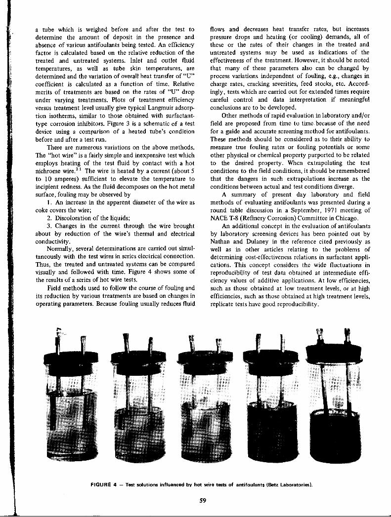
a tube which is weighed before and after the test todetermine the amount of deposit in the presence andabsence of various antifoulants being tested. An efficiencyfactor is calculated based on the relative reduction of the
treated and untreated systems. Inlet and outlet fluidtemperatures, as well as tube skin temperatures, aredetermined and the variation of overall heat transfer of "U"coefficient is calculated as a function of time. Relative
merits of treatments are based on the rates of "U" dropunder varying treatments. Plots of treatment efficiencyversus treatment level usually give typical Langmuir adsorption isotherms, similar to those obtained with surfactant
type corrosion inhibitors. Figure 3 is a schematic of a testdevice using a comparison of a heated tube's conditionbefore and after a test run.
There are numerous variations on the above methods.
The "hot wire" is a fairly simple and inexpensive test whichemploys heating of the test fluid by contact with a hotnichrome wire.21 The wire is heated by a current (about 5to 10 amperes) sufficient to elevate the temperature toincipient redness. As the fluid decomposes on the hot metalsurface, fouling may be observed by
1. An increase in the apparent diameter of the wire ascoke covers the wire;
2. Discoloration of the liquids;3. Changes in the current through the wire brought
about by reduction of the wire's thermal and electricalconductivi ty .
Normally, several determinations are carried out simultaneously with the test wires in series electrical connection.Thus, the treated and untreated systems can be comparedvisually and followed with time. Figure 4 shows some ofthe results of a series of hot wire tests.
Field methods used to follow the course of fouling andits reduction by various treatments are based on changes inoperating parameters. Because fouling usually reduces fluid
flows and decreases heat transfer rates, but increases
pressure drops and heating (or cooling) demands, all ofthese or the rates of their changes in the treated anduntreated systems may be used as indications of theeffectiveness of the treatment. However, it should be notedthat many of these parameters also can be changed byprocess variations independent of fouling, e.g., changes incharge rates, cracking severities, feed stocks, etc. Accordingly, tests which are carried out for extended times requirecareful control and data interpretation if meaningfulconclusions are to be developed.
Other methods of rapid evaluation in laboratory and/orfield are proposed from time to time. because of the needfor a guide and accurate screening method for antifoulants.These methods should be considered as to their ability tomeasure true fouling rates or fouling potentials or someother physical or chemical property purported to be relatedto the desired property. When extrapolating the testconditions to the field conditions, it should be remembered
that the dangers in such extrapolations increase as theconditions between actual and test conditions diverge.
A summary of present day laboratory and fieldmethods of evaluating antifoulants was presented during around table discussion in a September, 1971 meeting ofNACE T-8 (Refinery Corrosion) Committee in Chicago.
An additional concept in the evaluation of antifoulantsby laboratory screening devices has been pointed out byNathan and Dulaney in the reference cited previously aswell as in other articles relating to the problems ofdetermining cost-effectiveness relations in surfactant applications. This concept considers the wide fluctuations inreproducibility of test data obtained at intermediate efficiency values of additive applications. At low efficiencies,such as those obtained at low treatment levels, or at highefficiencies, such as those obtained at high treatment levels,replicate tests have good reproducibility.
FIGURE 4 - Test solutions influenced by hot wire tests of antifoulants (Betz Laboratories).
S9

However, poor reproducibility at intermediate concentrations and efficiencies limits the ability to differentiatebetween the cost-effectiveness of alternative additives.
Similar difficulties have been reported with respect to theevaluation of corrosion inhibitors in refinery processes andother applications22 and in testing the effect of surfactantsemployed as corrosion inhibitors and/or antifoulants on thewater tolerance of jet fuels (WSIM Test). The limitations ofscreening tests emphasize the inadvisability of unduereliance on them and the need for following such tests withcareful plant studies to obtain reliable technical andeconomic data on antifoulant applications.
References1. J. 1. Bregman. Corrosion Inhibitors, p. 257, The MacMillan Co.,
New York (1963).2. B. W. Weinland, R. M. Miller, and A. J. Freedman. Reduce
Refinery Fouling, Materials Protection, 6, 41-43 (1967)February.
3. J. A. Biehl and E. A. Schnake. What Ohio Oil Learned in 5
Years of Procession Crude Oil at Low pH, Oil and Gas J., 57,No. 23, 125 (1959).
4. W. F. Taylor and T. J. Wallace. Kinetics of Deposit Formationfrom Hydrocarbons, I & E.C. Prod. Res. Dev., 6, No. 4, 258(1967) December and 7, No. 3, 198 (1968) September.
5. A. Gonzalez, D. 1. Hagney, and N. E. Sumner. The Evaluationand Application of Metal Coordinating Antifoulants, NACESouth Central Region Conference, New Orleans, La., October18-21,1965.
6. A. C. Nixon and H. B. Minor. Effect of Additives on Jet FuelStability and Filterability, Ind. and Eng. Chem., 48, 1909(1956) October.
7. L. R. Mahoney. Antioxidants, Angew Chem. InternationalEdition. 8, No. 8,547 ff (1969).
8. J. P. Luvisi and J. A. Chenicek. U. S. Patent No. 3,023,161.9. See list hereunder.
10. C. C. Nathan and C. L. Dulaney. Statistical Concepts in Testingof Dispersants, I. & E.C. Prod. Res. and Dev. (1970) December.
11. A. S. Couper and F. B. Hamel. Process Side Antifoulants in
60
Petroleum Refineries, Report of Work Group T-8-2a, MaterialsProtection, 9, 29-33 (1970) June.
12. Oil and GasJ., 118 ff (1961) April 17; 115 ff (1967) March 13;114 ff (1968) March 25; 77 ff (1969) February 17; 115 ff(1969) March 3; 69 ff (1970) February 16; 74 ff (1970) April13; 67 ff (1970) March 9; 202 ff (1970) March 16.
13. D. M. Smith. Antifouling Agents in Refinery Equipment,Materials Protection,S, 51-52 (1966) June.
14. G. R. Port. Antifoulants and Inhibitors Reduce Fouling andCorrosion of Refinery Equipment, Materials Protection, 7,29-32 (1968) September. See also: G. R. Port. Mitigation ofFouling and Corrosion in Refinery Processes Utilizing Antifoulants and Inhibition, Proc. NACE 24th Cont., pp. 653-659,National Association of Corrosion Engineers, Houston, Texas.
15. Corrosion, Metallurgical and Mechanical Experiences of Petroleum Refinery Compressors. Interim Report of NACE Technical Group T-8-1, Proc. NACE 24th Cont., pp. 660-673,National Association of Corrosion Engineers, Houston, Texas.
16. W. F. McFatter. Reliability Experiences in a Large Refmery,Chem. Eng. Prog., 68,52 (1972).
17. K. E. Coulter and V. S. Morello. Improving Onstream Time inProcess Plants, Chem. Eng. Prog., 68,56 (1962).
18. C. C. Nathan. Use of Chemicals for Solution of RefmeryCorrosion and Related Problems, Materials Protection, 9,15-18(1970) November.
19. A. W. Frazier, J. G. Huddle, and W. R. Power. New FastApproach to Reduced Preheat Exchanger Fouling, Oil and GasJ., 117, (1965) May 3.
20. B. G. Gillespie. A New Process AntifouIant Test CorrelatesBetter with Refinery Experience, Paper 40, NACE 27thConference, March, 1971. Sce also Mat. Pro. & Pert., 10, No. 8,21-25 (1971) Aug.
21. Anon. Simple Device Tests for Foulants, Oil and Gas J., 96(1969) February 3.
22. C. C. Nathan and C. L. Dulaney. How Statistical ConceptsFacilitate Evaluation of Corrosion Inhibitors, Materials Protection, 10,21-25 (1971) February.
23. C. C. Nathan and C. L. Dulaney. Statistical Aspects ofSurfactant Evaluation Applied to Water Tolerance of Jet Fuels,AIChE 68th National Meeting and 6th Petroleum Conference,Houston, Texas, February 28-March 4, 1971. See also WaterSeparometer Test Is Tricky. Hydro. Proc., SO, No. 8, 129,(1971) Aug.

AL NESTLE*
Corrosion Inhibitors inPetroleum Production Primary Recovery
The discovery of the inhibitive properties of long chain,high molecular weight polar materials about 25 years agodramatically altered the pattern of inhibition practices onprimary production oilwells and gas wells. It permitted longterm operation of wells which otherwise might not havebeen economical to keep in production. The inhibitors alsohelped to increase the percentage of the total fluids thatcould be taken from reservoirs.
During the past decade, the principal improvements ininhibition practices have been in the refinement of formula
tions and the development of better ways to applyinhibitors and to evaluate their performance during use. Alarge share of the attention given to inhibitors used forprimary production has been to determine with greaterprecision their probable effects when used in wells.
The economics of inhibition have been materiallyimproved by new methods of application. Benefits achievedhave been especially important to the industry because ofthe increased costs of producing from offshore zones andthe deeper drilling required to get production. Ecologicalconsiderations have emphasized the importance of maintaining the integrity of production equipment, especiallythat located in coastal waters and rivers.
Characteristics of Oil and Gas WellsWhile there are many other ways to categorize oil and
gas wells, this chapter considers them in the followingbroad categories:
1. Oil-that is, producing mainly liquid hydrocarbons.2. Gas-that is, producing mainly gaseous hydro
carbons.
3. Condensate-that is, producing significant quantitiesof liquid hydrocarbons along with gas at high pressures andtemperatures.
Each of these may be divided into "sweet" or "sour",designations which are a function of the amount of
hydrogen sulfide produced. Because there is no unqualifieddividing line between sweet and sour with respect to thequantity of hydrogen sulfide produced, there are somewells that may be classified in either category. lt is usuallyaccepted that even a trace of hydrogen sulfide may besufficien t to categorize a well as "sour".
Other gases, including carbon dioxide, and formic,
*Houston, Tx. Formerly Corrosion Technologist, Production Chemistry Group, Texaco Research Laboratories, Houston, Tx.
61
acetic or other short-chain aliphatic acids may be producedto a greater or lesser extent. These gases and acidscomplicate the problem of inhibiting corrosion of wells inwhich they are present.
Furthermore, because corrosivity frequently is proportional to the ratio of produced water to hydrocarbons, thevolume and composition of produced water influence theperformance of inhibitors. Another major influence is theproduction mode of the well, that is, whether it is flowing,pumped or produced by gas lift.
Influence of Well Depth, Completion MethodAs well depth increases, bottom hole temperature rises.
For this reason it has been necessary to develop inhibitorsthat will function at higher temperatures than wereprevalent a decade ago.
Other aspects of the cost of drilling, such as thetechnique of producing from more than one stratum in onecasing also influence inhibitor practices. High labor andequipment costs offshore introduce a factor of economic
risk in the application of inhibitors, making the effect offailure more important than heretofore. This had made it
necessary to carefully screen inhibitors for anticipatedperformance and to select application methods with care.Increasing the duration of inhibition is important so thatintervals between treatments can be lengthened.
Economics of InhibitionThe economics of inhibition as discussed in J. I.
Bregman's book1 are probably more favorable now thanthey were a decade ago when he said that inhibitors showed
a 7 to I payout in oil wells and better than 4 to 1 in highlycorrosive condensate wells, in spite of the increased cost oflabor, equipment and taxes. The cost of inhibitors has notshown a marked increase.
An estimate by Phenicie2 of petroleum productioncorrosion costs in 1966 indicated that the oil industry inthe United States spent 16 cents per barrel of producedcrude for corrosion losses and control measures or about
$450 millions a year. About $25 millions annually wasspent for corrosion control chemicals. He estimated that$10 millions of the estimated $12 millions cost of
condensate well corrosion (1951) could have been saved byproper corrosion control measures. There is reason to
believe savings would be greater today than they were then.

Well pulling jobs of Huntington Beach, Ca!. wells werereduced from an average of 5.7 per well per year to 1.6 byan effective inhibitor, program.(1) Cost of the chemicalcontrol program was only 5 percent of subsurface maintenance costs for·these wells.
Numerous other instances of substantial savings havebeen repeatedly reported in technical journals.
Data on possible savingsin producing operations weregiven in a survey published by Robinson and Waldrip.3Theratio of savingsfrom corrosion control varied from less than4 to over 8 to one, both substantial benefits, althoughprofit calculations may have been partial or incomplete inmost of the cases reported.
Continuing work by NACE T-IH Unit Committee onEconomics of Corrosion Control resulted in an article titled"Economics of Petroleum Production," by Park and Roberson.4 The article covers the application of "time value ofmoney" and "federal, state and local income taxes," toexpenditures or income and makes it easier to compare cashoutlays to extended payments. This material is scheduled tobe used in forthcoming edition of a book on oil and gaswell corrosion.
To assist in the economic appraisal of corrosion controlmeasures, NACE has published its Standard RP-02-72:Recommended Practice-Direct Calculation of EconomicAppraisalsof Corrosion Control Measures.
Factors Influencing Corrosivityof Produced Fluids
Characteristics of Fluids
Produced fluids vary from non-corrosive liquid orgaseous hydrocarbons to severely corrosive waters andbrines. Produced mixtures of gas, liquid or solid hydrocarbons and waters also vary from non-corrosive to severelycorrosive, not necessarily in proportion to the waterfraction, which may vary from less than one to over 99percent.
Methods of monitoring the severity of corrosion arecovered elsewhere in this book. Predictive methods basedon information from produced fluids, samples, well tests,experience with similar wells are readily available in theliterature. Some of the principles governing the corrosivityof produced fluids are discussed below.
Temperature, Pressure Velocity
The effect of temperature on corrosion of petroleumproduction equipment is similar to its effect on otherchemical reactions. Because rates of many corrosion reactions increase with temperature, doubling with each rise of20 F (11 C), temperature effects should be taken intoaccount.5
Secondary pressure effects may have more influence oncorrosion reactions than primary effects of pressure orreaction rates. Acid gas solubility changeswith temperature
(I)H. 1. Kipps. The Practice of Corrosion Control in a California OilField-Four Case Histories. Proc. 1971Western States CorrosionSeminar. NACE, Houston, Tx. (1972).
62
and pressure are two significant possibilities. Pressures inwells may exceed 12,000 psi6 and temperatures may beover 400 F (200 C). Many corrosion inhibitors loseeffectiveness at high temperatures.
Cyclic Loading, Stress, WearCorrosion inhibitors especially suited to control corro
sion accelerated by stress, cyclic loading or hydrogenembrittlement have been reported in the literature byChittum,7 Bates,8 Hudgins,9 and Patton.1 0 Control requires preliminary investigations of candidate materials intest simulating the environment created by the accelerants.The extra expense usually is more than repaid by theresulting safe operating conditions.
Wear occurs in pumping wells and others in whichconditions are conductive to rubbing contacts. These canoccur at many places in the long "strings" which sometimesgo down over 4 miles. Few wells are vertical throughout.Pumping rods moving vertically as many as 60 strokes aminute have slidingcontacts at many places. Couplings thatjoin the 25-foot segments rub against the tubing, so, ifcorrosion inhibitors are not also superior lubricants, metalloss can be seriOUs.Also, tubing strings in pumping wellsoften slide against the outer casing or other structures (forexample, packers).ll Figure 1 illustrates the consequencesof poor practices in a pumping well and benefits of goodinhibition.
Ero~on,Abraswn,cavftanon
"Sand control" measures are designed to prevent f'mesolids from being produced with the hydrocarbons andwater. These measures reduce the harmful effect of theseparticles on moving parts. Cavitation effects may occur onthe trailing surfaces of rapidly moving parts as the result ofthe formation and collapse of vacuum bubbles in the liquidat the metal-liquid interface. Inhibitors sometimes nelpreduce cavitation attack.
Recommenaations are often made that corrosion control measures be used on all wells beginning with theirinitial production because it is more economical to treatinitially and continue treating than to monitor and delaycorrosion control until the need is positively demonstrated.Frequently, delay causes expensive failures which couldhave been prevented. These usually are followed byadditional failures, no matter how effective the controlmeasures initiated.
Determining Well Fluid Co"osivity"It has been found that wells often become corrosion
problems when total water cut passes 85 percent, althoughthere seem to be occasional exceptions. Amount ofemulsion carried in the well fluids will affect the fluid'sresistivity and thereby the effectiveness of fluids as anelectrolyte. In general, therefore, wells producing largevolumes o~ water with little emulsion should be relativelymore corrosive than lower-cut wells with emulsion pres·ent."12
Early studies made by the National Association ofCorrosion Engineers and Natural Gas Producer's Associ-

FIGURE 1 - (Top) Polished rod couplings after severalmonths' service in a crooked holed well producing severelycorrosive fluids shows the advantage of inhibitor treatmentwhich reduced corrosion and wear. (Bottom) Corrodedcouplings from a well exposed to severely corrosive wellfluids without proper inhibition. (Bottom: Figure 1 "Corrosion Control in the EastTexas Field. B. W. Cato. Mat. Pro., 1,
No. 5, 58-67 (1962) May).
ation committees resulted in designating two types ofcorrosion:
1. "Water-independent" corrosion that occurs in sweetor sour oil and gas wells when as low as 0.1 percent water isproduced. Corrosion activity (severe) begins at initial waterproduction in this class of well.
2. "Water-dependent" corrosion develops in oil and gaswells that produce high percentages of brine. Corrosionactivity may not begin in this class of well until after severalyears of production.! 3
Bregman! summed up prediction of corrosivity in thesewells: "Gas condensate wells are a major corrosion problem. These wells have high gas-to-oil ratios under very highpressure. The condensation of large volumes of hydrocarbons is accompanied by the formation of a small amount ofwater which contains carbon dioxide and low molecular
63
weight fatty acids. This situation results in an aggressiveacid attack which may include severe pitting."
The relationship of pressure and corrosion in gascondensate wells has been described in the NGPA condensate well corrosion book! 4 as follows:
1. A partial pressure of carbon dioxide in the gas above30 psi usually indicates corrosion.
2. A partial pressure of carbon diodide between 7 and30 psi may indicate corrosion.
3. A partial pressure of carbon dioxide below 7 psi isconsidered non-corrosive.
This breakdown is widely accepted and is the onlystatement of its kind in the literature on corrosion.
An examination by Shock and Sudbury!5 of therelative influence of carbon dioxide and the fatty acids oncorrosion of gas condensate wells showed that carbondioxide was the primary causative agent. Organic acidscause general, rather than a pitting type corrosion associated with carbon dioxide. The corrosion rate of steel due to
organic acids decreases with time; the reaction is self·stifling. Fatty acids cause carbon dioxide attack to occur atlower concentrations than would be the case otherwise.
Results of additional work on predicting corrosion aresummed up as follows by Farrar!6: "Approximately 30percent of the country's low-pressure, sweet-oil wells are"economically affected" (annual corrosion cost $200 ormore) by water-dependent corrosion. The annual cost ofcorrosion is $960 per well, even with remedial measures.
The average low-pressure well experiences 11 years ofrelatively trouble free operation before corrosion sets in.After corrosion starts, tubing life is reduced to an averageof 3 years and may be as low as 6 months.
The average low pressure corrosive well is producedfrom a depth of 5050 feet, with average bottom holepressure of 2275 psi. Average bottom hole temperature is160 F (70 C).
Previous papers have summarized water-independentcorrosion which occurs at high pressures, usually from thebeginning of the well's production history.! 7-20 Relationship to water production ... only a small proportion oflow-pressure wells producing less than 40 bbl of water a dayare corrosive, while 75 percent of those making greater than100 bbljday are corrosive. However, there is no directrelationship between volume of water produced and corrosion.
"Wells making large amounts of water usually have highlifting costs and the added burden of corrosion expenditure can result in operation at a loss. Water-oil ratio has aprimary influence on whether a given well in a corrosionsusceptible field is corrosive. Figures on a number ofcorrosive fields show: 0 to 20% water- 0% of wells
corrosive; 20 to 40% water-O% of wells corrosive; 40 to60% water-74% of wells corrosive; 60 to 80% water-I 00%corrosive and 80 to ]00% water-l 00% corrosive."! 6
Similar information came from GreenweIl2!: "The
ratio of water in the produced fluids may vary from lessthan 1 to over 99 percent water. Corrosion in oil wellsgenerally increases (with the water cut) according to fieldexperience." Low pressure oil wells producing gas contain-

ing carbon dioxide were "corrosive" according to thepercentage of water produced. The water is usually brinefrom less than 1% to over 10% sodium chloride.
It is believed that characteristics of produced fluidsaffect corrosivity. However, estimates of the percentage ofsour wells producing corrosive fluids varied widely and sourproduction was not necessarily corrosive in all cases. AnNACE committee in 1952 surveyed over 8000 sour oil wellsand found 44 percent to be economically affected bycorrosion.22 This percentage undoubtedly has increasedbecause of the growing use of secondary recovery methods.
Bass23 said in an article that corrosion inhibitors were
needed in 80 percent of all crude producing wells.Sour fluids may cause more severe corrosion than
sweet, but there are exceptions. Organic inhibitors suitablefor good continuous treating and good persistent filmingappear to work better with sour fluids than with sweet.While percent protection obtained by these effectivematerials is higher in sour environments, this is due usuallyto the greater unprotected corrosion rates common in sourenvironments. Nevertheless, absolute corrosion rates with
good inhibitors are as low as or lower in sour environmentsthan they are in sweet environments.
Some of the bad reputation sour fluids have for severecorrosion is justified because, without protection, moresevere types of corrosion of the harder steels are possible inthem. Accelerated and localized corrosion which occurs
also in sweet fluids and especially in improperly orimperfectly inhibited sweet fluids, can be more severe thanin similarly handled sour fluids. Sour fluids may causehydrogen blistering and stress corrosion cracking but mayor may not be worse than sweet fluids in causingaccelerated wear or corrosion fatigue. An analysis of thefacts might show that corrosion by sour fluids is notnecessarily more difficult to control than is corrosion bysweet fluids. 2 4,25
Regardless of the merits of the various means to predictcorrosivity, it is perhaps safer to agree with the following:"1t is good insurance to assume that corrosion conditionswill exist ... and act to control them effectively by one ormore of the excellent corrosion control methods available
as applicable to the assumed corrosion conditions." (page 3,Reference 6).
Hydrogen Sulfide AttackThe solution of hydrogen sulfide stress corrosion
cracking is mainly in metallurgy. Experimen tal and practical evidence shows that the tendency of steels to stresscorrosion crack under the influence of hydrogen sulfide isrelated to alloying elements in the steel and to phasestructures and hardness. The most recent guidance on theselection of materials for sour service is contained in NACE
Publication 1 F 166 (1973 Revision): Sulfide CrackingResistant Metallic Materials for Valves for Production and
Pipeline Service. This is a report of NACE Unit CommitteeT-l F on Metallurgy of Oil Field Equipment.
Inhibition has a secondary role in reducing theamount of corrosion and thereby reducing the quantity ofhydrogen produced at the electrolyte-metal interface. This
64
FIGURE 2 - Typical electron micrographs of 4340 steelshowing results of heat treatment to reduce stress crackingsusceptible martensite. A = Treated 1 hr at 1400 F (760 Cl; B= Treeted 1 hr at 1400 F plus tempered at 1200 F (649 Cl.E. Snape. F. W. Schaller. R. M. Forbes-Jones. A Method ofImproving Sulfide Cracking Resistance of Low Alloy Steels,Proc. NACE 25th Conf., NACE Houston, Tx. p116.

hydrogen is usually assigned a major role in stress corrosioncracking due to hydrogen sulfide attack.
Figure 2 shows the results of heat treatment of highstrength steel to reduce marten site content. Martensitecontent is believed to be a factor in hydrogen sulfideattack. This is only one of the ways that metals can beadapted to corrosive oil well environments.
Methods of Inhibitor Application
Continuous Treatment
In the continuous treatment mode, inhibitors areapplied in oil wells in the same way that demulsifiers are,by a chemical proportioning pump or by frequent batching.When continuous treatment is practiced, adsorption of theinhibitor is slow and desorption rapid whenever concentration in the well fluids drops to a level inadequate forprotection. Treatment often is begun at high concentrationsto produced a fast initial film. Continued treatment at highconcentrations, however, may not improve results and mayeven reduce protection. Maintaining excessive protectionmay be prohibitively expensive.
Protection obtained using continuous treatment maybe over 95 percent and may reduce uniform corrosion ratesto less than 1 mil a year. An inadequate inhibitor orinsufficient concentration may increase average corrosionrates or change uniform corrosion to a pitting type.Inhibitors must mix or dissolve in well fluids, stay withindefmite concentration limits and try to contact all metalsurfaces to be protected.2 6 ,2 7
. Treatment levels usually vary from less than 25 to over100 parts per million (0.0025 to 0.01 percent) based on thefluids carrying the treatment. At these low levels, solubility,dispersability or miscibility may be obtained easily.
It is essential to check zones where stream velocity islow to be sure that concentrations of inhibitor in these
zones are sufficient to give adequate protection.
Droplets of inhibitor in the 30 to 40 micron range asshown in Figure 3 have been prepared using weightedamines encapsulated in a water-soluble sheath. Their smallsize permits them to move freely through the producingsystem and their weight causes them to drop through thefluids to low levels. When the capsule is dissolved, theinhibitor is released into the fluids. Two tests with this
material showed satisfactory results.
Intermittent Treating
Intermittent treating achieves persistent filming byinfrequent batching of large quantities of inhibitor. Smallerquantities of chemicals may be used overall than incontinuous treatment. More economical and better protection often is possible with intermittent treating than withcontinuous treating.
The inhibitor may be used undiluted, as a uniform
special mix with diluents or mixed with a portion of thewell fluids.
Treating mixes should quickly form protective andpersistent films. Protection achieved may exceed 99 percentwith uniform corrosion rates of less than 0.1 mil per year.
65
FIGURE 3 - Droplets of encapsulated amine inhibitordesigned to be introduced into oil wells. The large black dotis an agglomeration of several capsules. X625. J. E. Haughnand B. Mosier. Micro-Encapsulation-A Method of LongTerm Inhibition for Oil Wells. Mat. Pro., 3, No. 5, 42-50(1964) May.
Essentially all the metal to be protected must be contacted.The inhibitor preferably should be a fast-filmer and be
insoluble both in any diluent used to aid in injecting themixture and also in produced fluids. Neither the treatingmix nor the well fluids should dissolve the film. Retreat
ment must be done at sufficiently frequent intervals to avoidoverextended intervals between treatings. The penalty fordelay may be accelerated and/or pitting corrosion.2 8
Economical use of inhibitors to produce longlastingand highly protective films depends upon infrequent batchtreating, supplemented by interim applications to repair thefilm or protect untreated metal inserted into the system.Most corrosive wells are amenable to a regime based onearly initial application, preferably long before critical needis manifest. Interim applications should follow at conservatively spaced intervals.
Regular treating intervals under optimum conditionsrange from 3 to 6 and even as much as 12 months in some
cases, not necessarily on low corrosivity systems. Application methods include all means of coating the metal to beprotected.
Concentrations range from undiluted to less than 0.2volume percent dispersed into diluen ts. Contact with the
metal may be assisted by pipeline scrapers, pigs or otherdevices.
Weighting agents are used to get the inhibitor down to

the bottom of the well. Riggs and Shock29 describe acorrosion inhibitor heavy enough to sink through the liquidcolumn in an oil well. The formulation consists of an
oil-soluble inhibitor, an immiscibilizing agent and a mutualsolvent. The mixture has a specific gravity of 1.1 (9.2 Ib/gal('" 1100 g/1). A typical example consists of a dimeric acid(polymerized linoleic acid), polyethoxylated sorbitanmono oleate and C6H4 Ch. These materials are now made
without chlorinated hydrocarbons and use either inorganicor organic weighting agents to give densities of over 14Ib/gal (1680 g/l). They are described in detail as toapplications, fall rates and other attributes by Bundrant,30Michnick, Annand and Farquhar31 and Patton, Deemer andHilliard.32
It is evident that a great deal of trouble is taken tomake certain that the inhibitor is available at needed
locations. Dramatic results are obtained using stick-typeinhibitors in wells not previously susceptible to protectionby liquid inhibitors. Substitution of the same inhibitor instick form often results in a sharp reduction of a well'scorrosion rate and a considerable savings in maintenancecosts.
Even weighted inhibitor sticks do not always reachbottom, so some operators have pushed them down withwire line tools. Others are trying bottom-hole injection, but,because of gelling of diluents in wells with high bottomhole temperatures, problems are being encountered.
Squeeze Treating Techniques
Squeeze treating is applicable to any well with sufficiently porous strata. It will result in essentially continuoustreatment as inhibitor is slowly released with producedfluids from the strata. True intermittent treating can beachieved by using persistent ftlming inhibitors to ftlm themetal as they go toward or are removed from the porousstrata. Film repair may be accomplished subsequently by ashort-time application of high concentrations. Inhibitorreturn from porous strata probably does not occur at auniform rate.
In this widely favored technique, a drum (50 to 55 gal.189 to 2661) or more of inhibitor is injected under pressureinto the producing formation so that the chemical willpenetrate and be adsorbed on the strata and then graduallydesorb as fluids are produced. This procedure often leads tocontinuous feedbacks lasting anywhere from three monthsto a year. An "over flush" of oil or brine consisting of a fewto more than 350 barrels is used to push the inhibitorfurther into the formation. 33,34 A primary advantage ofthis method is that it successfully treats many wells whichare packed off or have high fluid levels are are thereforedifficult to treat by other methods. In addition, treatmentfrequency is drastically reduced and a steady supply ofinhibitor assured over a long time. The technique requiresless manpower and is more reliable than other methods.The entire length of tubing is treated; treating and shut-intime are reduced and wear and tear on equipment minimized. These advantages are especially important in off·shore wells.34
The method is not without disadvantages, however.
66
The economic hazard is considerable because costs are highand the operator runs the risk of losing a great deal ofmoney at one time if something goes wrong or if badweather causes operations to be delayed.
The major concern is probably the possibility of thedevelopment of emulsion blocks or reverse-wetting in theformation which would reduce well production rates. Thisproblem has not been as formidable as first anticipated,although "tight" formations are still considered risky. 33The plugging effect of inhibitors on cores has been studiedin the laboratory by Kerver and Morgan.3 5,36
Squeeze treatments often can be completed in arelatively short time. For example, 2 to 4 hours may besufficient to treat a 10,000-ft gas condensate well at 5000psi.34
Squeeze treatments usually can be repeated indefinitelyand the consensus is that the second and succeedingtreatments have longer lives than the first, 37 possiblybecause some of the chemical used in the first squeeze istrapped in the formation and cannot return to the wellbore.
During the treating process, some of the inhibitor canbe squeezed into or adsorbed into low-permeability poresand fractures from which the fluid does not pass while thewell is working. These pores are saturated during the firsttreatment. The initial treatment also can alter the wettabil
ity of the formation to enhance adsorption on subsequenttreatments. Poetker and Stone38 describe how treatingcosts in the Placedo Field in Victoria County, Texas werecut about 50 percent and treating efficiency increasedabout 17 percent.
Squeeze treating was first tried in the mid fifties andrapidly gained widespread acceptance.3 9-4 5 Many inhibitors, undiluted or diluted with crude or rermed oils, lease
condensate, produced brine or fresh water were pumpedinto wells. Difficulties encountered can be considered due
either to side effects or excess well pressures that preventedsqueezing all of the desired volume into the formation.Success was reported and long-time, good corrosion controlwas achieved in most cases when the inhibitor was forced
successfully into the formation.
Tubing Displacement Results
Sometimes a squeeze treatment was successful whennone of the inhibitor was forced into the formation. This
"non-squeeze" variation came to be known as "tubingdisplacement." Based on later experience, it was claimedthat success from tubing displacements resulted because theinhibitor ftlmed the metal sufficiently to give lastingprotection. It is obviously impossible to obtain protectionequivalent to continuous treatment from this procedureunless a tight persistent, protective film is formed on themetal surfaces of the well. This mm had to withstand the
effects of flow, abrasion. contaminants and the corrosive
environment for the times reported. which oftenapproached those obtained from total squeezes.
Kerver and Morgan35 ,36 showed that some formationsresisted the flow of some types of squeeze mixtures. Theyalso studied cores and found that adsorption characteristics

FIGURE 4 - Gamma logs showing distribution of inhibitor
on tubing wall. Log 1 - 5 hr after start of injection. Log 2
2-21 hr after injection, well shut in. Log 3 - 26 hr after
injection, well flowing for 4 hr at 30 million cubic feet a
day.31
Importance of Inhibitor PropertiesWhen Treating Gas Wells
Information that should influence the choice between a
heavy liquid inhibitor or an inhibitor-diluent mixture whentreating gas wells is presented by Michnick, Annand andFarquhar,31 in "Batch Treatment of Gas Wells WithCorrosion Inhibitors: Tracer Experiments." Some of theirdata should be helpful also in estimating treating considerations involved in controlling corrosion in other types ofwells.
Data in Table I on the fall rates of inhibitors in six
wells can be used as a guide in selecting inhibitor type.Figure 4, from the same source, shows distribution ofinhibitor on tubing walls and the effect of time andresumption of flow reflected by measurements of gammarays from an isotope-tagged inhibitor. These data can beused as a guide to treatment selection.
LOG 3
o 2 4
LOG 1
c: 8
5
11 •..•._ •.•...•~ _02468 02468
Film Thickness in Mils
4
3
2
b 7oo
.c0.9'"o
10
o
'"
Lf6
'0
Treatment of Pumping WellsOther treatments producing effects similar to the
squeeze have been applied to pumping wells. They oftenrequire small volumes of fluid and less equipment than dosqueeze treatments. They do not call for unseating thepump and are called by various terms including "slug,circulate and park." The procedure calls for an appropriatevolume of chemical to be injected into the tubing-casingannulus instead of into the flowline. This causes the
chemical to be forced down the annulus into the pumpinlet and up the tubing. When the residue reaches thesurface, it is "parked" in the annulus and then theproduction is returned to the flow line. The residue reachesthe surface as a high concentration band or slug in wellfluids. Residual material is used to continue treatment byconstant concentration simulation or intermittent film
repairing and refilrning, similar to the manner in which thesqueeze treatment functions with its stored-in-theformation excess. Good results attained with these treat
ments are described by Fincher44 and in a report by Parkand Riley.47
Another method of treating pumping wells accomplishes approximately the same results as the slug-circulatepark treatment if the well has a high fluid level in thetubing-casing annulus. Called the "extended period batchtreatment," it introduces or circulates a large inhibitorvolume down the annulus at fixed intervals.
of various sandstones differed and that the adsorptioncharacteristics of limestones differed markedly from thoseof sandstones. Their work was extended and reported laterby Kerver and Hanson.46 Field studies with tracers werereported by Raifsnider, et al.47
Squeeze treatments have been successful with all kindsof wells. Pumping wells have been squeezed by injecting theinhibitor down the tubing after unseating the pump topermit fluids to pass the valves in the pump. Pumping wellsalso have been treated by injecting the inhibitor down thetubing-casing annulus. When using the latter method, agreater volume of fluid is required and the inside of tubing,rods and pump parts do not receive treatment initially butare filmed later by the inhibitor when it retums mixed withthe production. Treatment durations effective for ninemonths have been reported.4 7
TABLE 1 - Fall Rate of Corrosion Inhibitors in Gas Wells31
Depth
TubingInhibitorDiluentPumpingTypeFall RateViscosityWell
FeetinODGallonsGallonsgpmInhibitorfphcps
A·l
10,00023/827.500.5Normal2000105A-2
10,00023/827.527.50.5Normal300035B
11,60031/2553784.3Normal290013C
9,70023/827.501.2Heavy6002650
10,50031/2100 Heavy110026545
13(1 )3Heavy1300105(2 ) 10,000
23/85301.1Heavy1100265
(I )Five gal lease condensate and 8 gal water.(2)C. C. Patton, D. A. Deemer, and H. M. Hilliard, Jr., Oil Well Liquid Inhibitor Effectiveness, Materials Protection, 9, 37-41 (1970) February.
67

It may be better from the standpoint of improvingresults and minimizing shutin time to use low viscosityinhibitor mixtures that have greater volume but do notnecessarily cost more than heavy liquid inhibitors fortreating gas wells that empty on shutin. Similar treatmentsmight be used on other wells also except those which canbe killed when excess amounts of fluid are injected into thetubing.
Treatment With Heavy Liquid InhibitorsThe problem of getting corrosion inhibitors to the
metal surfaces by either constant concentration or persistent filming methods is comparatively easy to solve. Complications in addition to those resulting from mechanicaloperations include side effects such as formation of tightemulsions as thick as cold cream which may kill the well. Asqueeze treatment, still the most successful and economicalmethod, has similar problems in addition to complicatedlogistics involving large volumes to be pumped. This oftenrequires waiting on weather in inland and offshore waters.
Advantages of heavy liquid inhibitors offset some ofthese side effects by reducing the volume of fluid to beinjected so that wells are seldom killed and thick emulsionsformed less frequently. Twenty to fifty gallons of inhibitordropped down into the well usually require longer shutin(production off) times than either the squeeze or tubingdisplacement methods. Treatment cannot be expected to beas effective or to last as long as either of these lattermethods. Objections may be raised in some cases to the useof zinc chloride or other soluble zinc salts as weightingagents, reminiscent of the taboo on the use of chlorinatedhydrocarbons, the original weighting agents. Glycol orother organic weighting agents also are well tested andprobably more acceptable, provided a proper filming
TABLE 2 - Effectiveness of Heavy InhibitorTreatments as Reflected in Iron Contents
of Produced Water3 0
After Treatment
Field
WeeksMonthsppm
Puckett, Tx. before treatment
1622
412
19
Venice, La. before treatment
2501
405
258
25
Bateman Lake, La. before treatment
873
153
36
5
Sweet Bay Lake, La. before treatment
1856
83
45
6
68
mixture can be made compatible with the well fluids andwithout harmful side effects.
Heavy liquid inhibitors are used in treating pumpingwells. Their non-miscibility with hydrocarbons enablesthem to fall more easily through static columns ofhydrocarbons than most treating mixes. Less fluid volumeper injection is required. Continuous treating can beeffected by using frequent, small-volume batch additions.
True intermittent treating using persistent fIlming requireslarger volumes and reduced frequency. Additional information is in Bundrant's excellent article.3o Table 2 showssome of the results achieved in four fields.
Treating Special Types of Wells andMiscellaneous Types of Treatment
Heavy liquid inhibitor slugs are not the only means thatcan be used on wells that are easily killed, that is, wellswhich will not resume flowing without being swabbed,having the column lightened, etc., if production is stopped.Treating these wells imposes extra requirements such asmixes which lighten the column, foams, gases and the like.The use of reeled "macaroni" tubing (or running a string ofsmall diameter pipe to the bottom for treating pruposes)and/or gas lift to revive the well are some expedients. Thesmall diameter strings can either be left in the well or pulledout between treatments.
Wells that kill can be treated by forcing the inlubitorinto the formation or positively forcing the fluids intocontact with the metal and perhaps squeezing inhibitor intothe formation in the process by gas pressure (for example,dry gas, plant gas), liquefied petroleum gas or an inert gassuch as nitrogen. Then the well can easily be returned toproduction. Use of nitrogen to force fluids down and ofatomized treating mixes is described by Nunn and Hami!ton.48
Summary of Oil and Gas WellInhibition Practices
Many methods are used to protect oil field metal withcorrosion inhibitors including continuous or intermittenttreating and other more specialized methods to produce aconstant concentration or persistent inhibitor film. Application methods depend on the physical setup of the well, theavailability of inhibitors, labor, services and other factors.
For continuous treating, the inhibitor must be mixed
into well fluids, often with chemical pumps to inject therequired quantities. Maintenance problems have plaguedthese pumps, particularly when they are in locations visitedinfrequently, for example, once a day or less.
Inhibitior mixtures have been forced (squeezed) intoformations to feed back into produced fluids.
Inhibitors formulated into slow-dissolving solids, sticks,pellets, encapsulated droplets and as weighted liquids andother configurations have been used successfully for continuous treating.
Also, downhole dump bailers, chemical treatment
valves in tubing to feed inhibitor into the productionstream from annuli, concentric tubing of small diameterand special diffusing devices have been proposed or used.

Control of Acid Cleaning SolutionsAcids and acid inhibitors may be used to clean lines
and vessels in the oil field just as they are used in industry.They are described in this book in the chapter on acidinhibitors.
Acids and acid inhibitors are used downhole in the oilfield. Corrosion inhibitors for use with well stimulation acid
treatments or formation cleanouts for restoring injectivity
of disposal wells are specialized chemicals preferably chosenthrough simulated field operation tests. The specific metals,formations and contaminants should be tested under
operating temperature and pressure for the probable treatment times.
Billings, Knox and Morris describe these tests.49 Figure5 shows some of the equipment required for laboratorytests of inhibitors used to control corrosion by well
acidizing fluids. (Work is under way on standards applyingto the use of acid inhibitors by a joint NACE-AmericanPetroleum Institute committee). An excellent treatment onwell acid treatment mechanisms is found in Tedeschi, Nataliand McMahon's article.49a
FIGURE 5 - Top view of test unit to measure velocity andtemperature effects on inhibitors. The three container jarscan be rotated at speeds up to 190 rpm at temperatures up to250 F (120 Cl. Tests with the device showed velocity hadlittle or no effect if the inhibitor was arsenic compounds orpropargyl alcohol.49
69
Acid treatments downhole interrupt producing operations in several ways. Corrosion control programs, particularly those involving chemical corrosion inhibitors, may bedisrupted. The treating program in effect has to bemodified to accomodate the after-effects of acidizing.These modifications include stopgap treating with inhibitors to restore protective films removed by the acid.Standard inhibitors may not give good protection againstacid treatment. A special post-acidizing program with theregular corrosion inhibitor should be planned to followacidizing as soon as possible. A prerequisite is having alltraces of acid removed from the system.
Bactericides as InhibitorsThe life processes or the residues of the growth of
living organisms may aggravate corrosion or produce corrodents. Bacteria and algae as well as other organisms oftenare found in produced fluids. Consequently germicides,bactericides, bacteriostats, algaecides and similar compounds may influence corrosion rates if they reduce effectsof living matter. Physical conditions in a system may bechanged by organic growths to aggravate corrosion.
Sulfate reducing bacteria produce tubercles underwhich corrosion may be severe and highly localized andlead to pitting. They also produce hydrogen sulfide to makesweet systems sour. These examples and others are discussed by Jorda and Shearer,s 0 Baumgartners 1 and Sharpley.s2
Characteristics of Organic InhibitorsMost of the inhibitors used now are long chain
nitrogeneous materials. The most common, all long chainhydrocarbons (usually Cl 8 ) include
1. Aliphatic fatty acid derivatives.2. Imidazolines and derivatives.
3. Quarternaries.4. Rosin derivatives.
The first of these, aliphatic fatty acid derivatives can befurther broken down into:
1. Primary, secondary and tertiary monoamines.2. Diamines.3. Amides.
4. Polyethoxylated amines, diamines or amides.5. Salts of these materials.
6. Amphoteric compounds.Commercially available inhibitors which fall into these
various classifications are as follows, where R = C 18 H3 7
unless otherwise specified.1. Monoamines:
a. Primary: R-NH2.b. Secondary: R2-NH.c. Tertiary: R-N(CH3)2'
2. Diamines: R-NHCH2CH2CH2NH2.3. Amides: R-CONH2.
4. Polyethoxylated materials:a. Amines (where x + y varies from 2 to 50):
..•..(CH2 CH2 O)xHR-N,
(CH2 CH2 O)yH

b. Diamines (where x + y + Z varies from 3 to 10):
R-NCH2CH CH N.-CCH2CH20hHI 22,
(CH2CH20)zH (CH2CH20)yH
c. Amides (where x + y varies from 5 to 50):
o11 .....(CH2CH20)XH
R-C-N......{CH2CH20)yH
5. Acetic, oleic, dimeric, naphthenic, or phosphate acidsalts.
6. Amphoteric compounds:
CH3 CHCH2 COOH.I
R-NH
PfoW and Gregory5 3 patented the diamines RHN(CH2 )xNH2 in which R is an aliphatic or alicyclic carbonchain of 8 to 22 atoms and x is 2 to 10. The alicyclic oraliphatic group is preferably a resin acid (or high fatty acidresidue containing 18 carbon atoms) which can be obtainedfrom resin or tall oils, soybean of coconut oil or tallow. Inthe same patent Pfohl and Gregory say that oleic acid saltsof these diamines are still better inhibitors.
The reaction of the diamines with acids obtained by
partial oxidation of certain liquid hydrocarbons waspatented by Jones.54,55 A typical example is the salt ofDuomeen- T and Alox 425.(2 )
Laboratory Testing of CorrosionInhibitors
The litera ture on corrosion control in the petroleum
industry has many references to testing methods designedto simulate field conditions. Ingenuous procedures attempt
analog methods to study corrosion control with actual wellfluids and metal, or the best available synthetic fluids.Variables encountered in the field are simulated within
practical limits by a variety of measures aimed at quantifi-cation of results. ,
Because corrosion fluids sometimes are quiescent, theycan be simulated by static tests, without the necessity ofcorrelating fluid flow effects. Oilfield examples of quiescentfluids are packer fluids and others left in tubing-casing orcasing-formation annuli. Shut-in wells or intermittent flowconditions in producing wells impose static conditions also.
Cooperative work done by NACE on testing is described below:
NACE Static and Dynamic Test Methods
Screening tests for both static and dynamic conditionshave been documented by NACE as the culmination of
»~
(2)Ouomeem-T, A tradename belonging to Armour Chemical Co.,Chicago, 111.(Amino Trimethylene Stearyl Amine). Alox 25, atradename belonging to Alox Corp., Niagara Falls, N. Y. (Fattyacid prepared by oxidation of selected petroleum fractions).
70
many investigations by laboratory workers. More than twodecades ago varieties of test methods designed to discriminate among inhibitors were developed and reported inNACE journals.
In 1960, a static test was formalized out of the work
done by Spalding and Grec05 6 as a "Proposed StandardizedStatic Laboratory Screening Test for Materials to be Usedas Inhibitors in Sour Oil and Gas Wells." This was identifiedas NACE Publication 60-2.57 It used chemicals at concen
trations equivalent to cost of 100 ppm of $2 a galloninhibitors, based on total fluids. Mild steel, cold rolled
coupons were exposed for about a week and were evaluatedon a weight loss basis. Static tests produce results applicableto static conditions and also are useful as a preliminaryscreening before the more time consuming and detaileddynamic tests. Dynamic testing reported by many workersinvolved a wide array of methods including rotated andtumbled bottles, coupons exposed on the perimeter of arotating wheel, shaking machines, stirring devices andothers. Various sizes and configurations of flat, rectangularor circular coupons as well as sections of rods and pipe wereused. Evaluation was by weight loss, pitting, film persistence, fIlm resistivity, hydrogen evolution, drop-size ratioand electrical resistance. In 1970 NACE published StandardTM-02-70: Test Method-Method of Conducting ControlledVelocity Laboratory Corrosion Tests, which is applicable toinhibitor evaluation.
NACE also developed a standard coupon(3) which canbe used in a wide variety of tests.
Tables 3 and 4 show some of the results obtained byvarious companies making dynamic tests. Figure 6 is adiagram of the criteria applicable to the drop size ratioevaluation method. Figure 7 shows results of tests toevaluate the influence of temperature on inhibitor performance.
(3)A standard coupon is available from NACE for use in monitoringinhibitor effectiveness or making screening tests. It allowsreplication studies in individual laboratorie.s and later comparisons of results among various laboratories. The coupon is madeof 1020 steel, measures 4314 x 1/2 x 1/8-inch with a 5/16-inchhole on a 3/8-inch center from one end. It is normalized aftercutting and stamping. Coupons can be obtained from TechnicalCommittee Secretary, NACE, P. O. Box 1499, Houston, Tx.77001.
TABLE 3 - Summary of Resultsof Multilaboratory Tests
on Inhibitor Film Persistence(1)
Effectiveness RankingInhibitor
FirstSecondThirdFourth
D
12(2)000B
101101A
0066
, C
0165
(1)Summary from Table 4. O. R. Fincher. Cooperative Evaluation of Film Persistency Tests.
( )Mat. Pro., 5, No. 10,69-73 (1966) Oct.2 Number of reporting laboratories.

TABLE 4 - Description of Test Procedures of Various Companies(1)
CouponTotalType
Area, Fluid,Company
Type ApparatusCouponssq cmRPMml
A
Rotating wheel· ....Rod 9.215175B
Rotating wheel· ....Strip 41.030450C
Rotating mounting boardRod10.426180Strip
11.7
D
Rotating coupon on plasticspindle
......... Strip52.5350350E
Rotating mounting boardRod9.3730175F
Short-arc horizontal shakerLong strip42170(2)350
G
Rotating wheel· ....Fixed strip4533250H
Rotating wheel· ....Long strip33434175I
Rotating mounting boardRod10.955120
(1)C. C. Nathan. Correlations of Oil-Soluble, Water-Dispersible Corrosion Inhibitors inOilField Fluids, Corrosion, 18, No. 8, 282t-28St (1962) Aug.
(2)Shaker movement in cycles per minute.
I
I ~ ~ .,.,.,.,.,."".,.,.,.,"",.,.,
• 2 3 4IFIGURE 6 - Configurations of drops used in evaluating themerits of oilwell inhibitors using the "drop size ratio"technique. Numbers 1 through 4 indicate order of increasingperformance. Drop 1 produces no wetting; 2 and 3 have a 0.5rating while 4 produces almost perfect wetting. (H. E.Waldrip and J. E. Rowe. Variables Influencing the Corrosivityof Oil and Gas Wells, Corrosion, 14. No. 2, 108-120 (1958)Feb.).
Applications of StatisticsThe statistical nature of the protection obtained from
continuous treating of oil field fluids with inhibitors wasthe subject of investigations reported by N athan andEisner.2 6,58 They showed that some inhibitors give poorprotection and even accelerate corrosion at low concentrations, but that data from replicate tests allow predictions ofvariations from the statistical mean. At optimum concentrations, the scatter is low when the protection is high. In theconcentration region between too little and enough, thedata are extremely variable, making it difficult to determinewhat protection can be obtained unless sufficient rcplicatc
100
Z0i=u
80w I-0Cl::~I-
60
z wUCl::w 40~ wCl«Cl::w20
> «0
...
I-
III
IIII IIII
I
III
IIIIIIIII
IIIII III I
IIIIIIIIIII
I
III
III III I
~
I III
IIII III I
-
IIIIIIIIIIII
-
IIIIIIIIIIIII
IIII: IIIIIII
I
IIIII
I II IIIII
I.
LKJ
231231231232 3
H
1 2 3G."
~NHIBITORS
2312312312312312A B C D E F
FIGURE 7 - Results of temperature on inhibitor performance. Numbers represent: Farenheittemperatures as follows: 1 = Room; 2 - 150; 3- 220. (Centigrade 21, 66, 1041. Figure 6. Corrosioninhibitor Evaluation at Elevated Temperatures. V. W. Maxwell, Corrosion, 16, No. 4, 201t-204t (1960)April.
71

(4)"Refined Oil 300" is a high-flash, low viscosity (42 SUS at 30 C(100 F) paraffin distillate oil. Brine = 10 percent sodium chlorideand 0.5 percent calcium chloride in distilled water.
Persistent FilminK TreatmCllt
I. To simulate persistent filming intermittent treatment, several coupon filming fluids were used. Usual
Iron Content Measurement
Results of tests on squeeze treatment of two condensate wells and two oil wells in South Louisiana and a gas liftoil well in South Texas were reported by C. C. Nathan.26Using iron content of produced fluids as a criterion for theLouisiana well squeezes, it was concluded that one condensate well had about six months' protection, but thatprotection of the others was questionable.
The South Texas well was a gas lift well producing 300barrels of gross fluid, 93 percent salt water. This well wassqueezed with a drum of "oil soluble, water-dispersable"inhibitor mixed with three barrels of oil and overflushed
with 8 barrels of oil. Success of the squeeze was measuredusing iron content.
Coupons A Iso Exposed
Downhole coupons were placed in this well prior to asqueeze and were removed at intervals until the last pairwas removed after six months. Short-term down hole
coupons were those exposed for the short interval betweenpulling the long-term coupons. The long-term couponsindicated that a squeeze treatment was giving 98 percentprotection; whereas, the short term coupons showed 98percent protection for the tIrst three weeks only. After thatthe rate steadily decreased to 35 percent for the last periodof exposure, which was 5 to 6 months after treatment.
The other methods showed that no protection wasbeing obtained by the squeeze after three weeks. Itappeared that corrosion protection was being obtained asthe result of persistence of the film on the tubing and/orfrom the initial slug of inhibitor that was produced whenthe well returned to production.
Monitoring Results of Inhibition
coupon filming time is one hour. Bottles containingcoupons and filming fluids were rotated on a wheel. Thefollowing combinations were used:
a. Refined 300 oil containing 2.3 percent inhibitor (Igal inhibitor to I bbl oil).
b. Fresh water containing 2.3 percent inhibitor.c. To simulate conditions after filming, coupons are
transferred to fluids containing 10 percent 300 oil and 90percent 10.5 percent brine.
2. To simulate conditions after filming, coupons aretransferred to fluids containing 10 percent 300 oil and 90percent brine (with no inhibitor) and run on a dynamicwheel for one hour. After this, coupons were transferred tofresh fluids consisting of 10 percent 300 oil and 90 percent10.5 percent brine (no inhibitor) and returned to thedynamic wheel for a 72 hour run.
Radio tracer Methods
Notable work using radioactive tracers has been doneby Raifsnider, et ai, in relating results from laboratory testsof the squeeze method to field results. Figure 9 shows theirresults. This study permitted identification of an application method Get stream) which produced benefits muchgreater than were achieved from dump bailer applications.
72
1.0.80.60.40
_ Inhibitor 1• Inhibitor 2+ Inhibitor 3• Inhibitor 4
Fraction Inhibition'" f.20
•
FIGURE 8 - Fraction inhibition vs fraction scatter forinhibitors 1, 2, 3 and 4.26
How to Make Simulated Field TestsIn a 1968 article, NestleS 9 reported on screening tests
of 48 commercial organic inhibitors used to control
corrosion in oil and gas wells. His methods were designed tosimulate field use and to gather data permitting a reductionof the number of formulas in inventory. Inhibitors wereevaluated in sweet and sour environments using simulationsof continuous treatment and persistent filming applicationmethods. Laboratory prepared fluids used were 300 oil( 4)
with 10.5 percent brine and 300 oil with fresh water.Details of the tests follow:
Colltinuous Treatment
I. An inhibitor concentration of 15 parts per million(ppm) was used. This is in the 10 to 100 ppm range (basistotal fluids), consti tu ting a severe test for many inhibitors.
1. More than one concentration should be tested if
possible.3. The inhibitor was mixed in and tested in fluids
consisting of ]0 percent 300 oil and 90 percent 10.5percent brine. Coupons were run on a dynamic wheel for72 hours. Before and after weight differences were compared with weight losses for similar coupons run 72 hoursin fluids containing no inhibitor.
4. Fluids from wells producing hydrocarbons andwater should be used also when possible.
tests are carried out. This may mean that each separateconcentration in any series of tests should have at least four
duplicate tests. This should be kept in mind when workingwith this kind of laboratory testing. Figure 8 graphicallyillustrates some results of Nathan and Eisner, showing howthe data deviate at different inhibitor efficiencies.
o
o
.30
::t"
~~ .20'"c
.~et

300
"1ii~c.s"or-8 100U
-- Instantaneous Daily Corrosion Rate--- - Cumulative mils (Daily Sampling)
Cumulative mils (Weekly Sampling)
Well Shut-in(Proration)
~-oil- -"1-
1. Installed Specimen2. Dump Bailed 5 qts. Diamine Salt3. Dump Bailed 5 qts. Diamine Salt4. Applied 30 qts. Imidazoline Salt
with Jet Stream5. Ran Caliper Survey6. Dump Bailed 5 qts. Imidazoline Salt7. Commenced Sampling Weekly8. Ran Caliper Survey
No
Samples
~ H ~
30
i20 §.;;;orroU~o
o
50 100 150 200 250Time. days
300 350 400
FIGURE 9 - Chart of corrosion data from 9600-ft gas lift well producing a mixture of 88 bbl oil and110 bbl brine daily. Data were taken using a cobalt-60 isotope source located in the producing stringof the well. Radioactivity of effluent was compared satisfactorily with concurrent weight loss data.Inhibitor was applied three times during 500 days by dump bailer and once'(70 days after start of test)by jet stream application. This method uses an applicstor which squirts inhibitor onto the walls of thetubing and wipes it over the surface with a felt pad. Low corrosion rates following this treatmentlasted almost a year. (Figure 1-Corrosion Monitoring in Oil Wells With a Radioactive Specimen. B. E.Gordon, P. J. Raifsnider and D. L. Lilly, Mat. Pro., 5, No. 11,21-3 (1966) Nov.
Techniques Applying to Coupons
Assessing the life of films produced by intermittenttreating (persisting fIlming) requires special techniques.Unless coupons have the same treating history as the metalin the well and are materials the same or essentially similarto well metals, coupon corrosion rates will not be equivalent to metals in the system. Coupons must be in thesystem when it is fIlmed or must be given a treatmentsimulating the filming. Under the heading "New IdeaTried," Smith37 reported in an article titled "CorrosionChecked in West Texas by Inhibitor Squeeze," the following:
"The probe installed on May 4, 1959 was submerged ina concentrated inhibitor solution before it was installed and
the data are much more in line with what was expectedfrom the treatment."
Inhibitor Optimizing NeededEven poor quality inhibitors sometimes give economi
cal protection when used according to good applicationpractices. This often confuses the issue to the extent thatno effort is made to determine how much better results
could have been obtained if better materials were employedwith the same care and precision.
Causes and effects in continuous treating are closelycoupled, while in persistent filming the lag between causeand effect can be lengthy. Squeeze treatments with goodinhibitors have been known to last for two years and aresuspected of lasting much longer. This means that longexposure times and many wells are needed along with
73
special types of monitoring to evaluate fully the results ofthese types of application.
Continual monitoring of results is more difficult whenthe persistent film technique is used than it is withcontinuous treating. While coupons, dissolved iron analysis,hydrogen probes, electrical resistance and polarizationinstrumentation all can be used, a more reliable coupon orother device is needed than is presently in common use tofollow the progress of intermitten t inhibitor effectiveness.
Quality Control and SpecificationsOilfield inhibitors usually sell for about $2 a gallon.
While there are many exceptions, in spite of inflation, theaverage price of most inhibitors will be close to this amountor even slightly less. Materials used in most inhibitors are
by-products of petroleum refining and other industries.
Although inhibitor formulators and vendors usuallyadhere to fairly rigid manufacturing specifications, most ofthem do not provide data from corrosion testing under fieldconditions. Quality variations from batch to batch have not
been controlled carefully by some compounders. While thecompounder relies on tests which may indicate significantdifferences in raw materials from batch to batch, these datahave little or no bearing on the performance of theinhibitor in the field. Since inhibitors may contain three ormore active ingredients in addition to solvents which canmaterially affect performance, considerable variations infield results can occur.
Many inhibitors are odorous, dark-brown materials
with color and/or odor caused by impurities not removed

when the inhibitors were synthesized and formulated. Thismakes it difficult to attach significance to what are called"active" materials. Even listing materials other than solvents or diluents does not help. A 1967 report of NACETask Group T-ID-S6o on quality control procedures usedin inhibitor manufacture revealed that less than half of the
27 manufacturers that supplied information regularly makecomposition analyses of raw materials going into theirproducts, while 64 percent tested physical properties andonly 18 percent checked performance. The survey alsoshowed that with respect to finished products, 40 percentmade composition analyses, 72 percent checked physicalproperties and 27 percent evaluated performance. Thesurvey covered what was believed to be about 90 percent ofthe volume of inhibitors used in oil fields.
Computer Aids in ControlsComputer oriented records permit faster, more ac
curate analysis of results from oilfield corrosion control
programs. Some of the systems now in use are described inan article by Hamner.61 Detailed reporting of events, whichinclude in some instances the exact identification of failed
equipment, the kind and cost of repair parts and laborexpense make it possible to closely monitor results ofinhibitor programs.
In another article by Bucuram and Sullivan,62 failuredata entered into a computerized system have provided ameans of predicting probable corrosion failures, thuspermitting corrective measures to be taken in advance.
Real time computer access makes machine evaluationof chemical treating programs economical. Treating manywells for corrosion and scale control requires constantupdating of treatment quantities on an individual well basis.This technique is discussed by Frye and Canaday.6 3
References1. J. I. Bregman. Corrosion Inhibitors, The MacMillan Company,
New York, (1963).2. J. W. Phenicie. Increased Petroleum Production Demands
Increased Corrosion Control, Mat. Pro., 5, No. 3, 23-4 (1966)Mar.
3. R. M. Robinson and H. E. Waldrip. Review of Survey Made onOil and Gas Well Corrosion Costs. NACE T-IH on Economics ofCorrosion Control (1963) June.
4. B. D. Park and G. R. Roberson. Economics of PetroleumProduction, Draft of chapter intended for Corrosion of Oil andGas Well Equipment, Division of Production, American Petroleum Institute.
5. V. W. MaxwelI. Corrosion Inhibitor Evaluation at ElevatedTemperatures, Corrosion, 16, No. 4, 20It-204t (1960) Jan.
6. D. R. Fincher, W. F. Oxford, Jr. and E. H. SulIivan. WellCompletion and Corrosion Control of High Pressure Gas Wells,Status Report, NACE T-IB-l, Corrosion, 15, No. 2, 73t (1959).
7. J. F. Chittum. Corrosion Fatigue Cracking of Oilwell SuckerRods, Mat. Pro., 7, No. 12, 37-8 (1968) Dec.
8. J. F. Bates. Sulfide Cracking of High Strength Steels in SourCrude Oils, Mat. Pro.• 8, No. 1,33-9 (1969) Jan.
9. C. M. Hudgins. A Review of Sulfide Corrosion Problems in thePetroleum Industry, Mat. Pro., 8, No. 1,41-7 (1969) Jan.
10. C. C. Patton. Corrosion Fatigue Problems in Petroleum Production, Corrosion 71 Paper 61, Petroleum Production-StringentCorrosion Control Procedures Key to Extended Fatigue Life,Mat. Pro. & Per!., 11, No. I, 17-8 (1972) June.
74
1I. A. Lubinski and K. A. Blekharn. Buckling of Tubing inPumping Wells, Its Effects and Means of Controlling It, AIMETrans., 210,73-88 (1957).
12. R. J. Villagrana and W. W. Messick. Economics of Oil WellCorrosion Control, Oil & Gas J., 48, No. 11,58-94 (1949) July.Also: APl Drilling and Production Practice, p391 (1949).
13. J. T. Martin. South Louisiana Operators Wage Fight on FourTypes of Corrosion, Oil & Gas J., 52, No. 7, 308-20 (1953)June 22.
14. Condensate Well Corrosion. Natural Gasoline Association ofAmerica, Tulsa, Okla (1953).
15. D. A. Shock and J. D. Sudbury. Corrosion Control in Gas LiftWells, Corrosion, 8, No. 9, 296-299 (1952) Sept.
16. G. L. Farrar. Combatting Corrosion in Oil and Gas Wells, Oil &GasJ., 51, No. 49,106-9, 111, 113 (1953) Apr. 13.
17. H. L. Bilhartz. Sweet Oil Well Corrosion, World 0iI,134, 208-16(1952) Apr.
18. H. L. Billiartz. How to Predict and Control Sweet Oil Well
Corrosion, Oil & Gas J., 50, No. 50,116-18,151,153 (1952)Apr. 21.
19. H. L. Bilhartz. Sweet Oil Well Corrosion, API Drilling andProduction Practice, p54 (1952).
20. H. L. Bilhartz. High Pressure Sweet Oil Well Corrosion,Corrosion, 7, No. 8, 256-64 (1951) Aug.
21. H. E. GreenwelL Studies on Water-Dependent Corrosion inSweet Oil Wells, Corrosion, 9, No. 9, 307-12 (1953) Sept.
22. J. A. CaldwelL Sour Oil Well Corrosion, Corrosion, 8, No. 8,292-94 (1952) Aug.
23. D. Bass. Preventing Corrosion by Crude: The Use of SurfaceActive Agents, Petroleum, 20,139-42 (1957) Apr.
24. C. M. Hudgins. A Review of Sulfide Corrosion Problems in thePetroleum Industry,Mat. Pro., 8, No. 1, 41-7 (1969) Jan.
25. C. M. Hudgins. Hydrogen Sulfide Corrosion Can Be Controlled.Petro. Eng., 13, No. 13, 33-6 (1970) Dec.
26. C. C. Nathan and E. Eisner. Statistical Concepts in the Testingof Corrosion InhIbitors, Corrosion, 14, No. 4, 193t-20It (1958)Apr.
27. C. C. Nathan. Correlations of Oil-Soluble, Water-DispersibleCorrosion Inhibitors in Oil Field Fluids, Corrosion, 18, No. 8,282t-285t (1962) Aug.
28. C. C. Nathan. Minutes of Record, NACE T-l Meeting, Oil andGas Well Corrosion, Oklahoma City, Okla. (1957) Oct. 1,Summary Corrosion, 14, No. 4, 27-30 (1966) Nov.
29. O. L. Riggs and D. A. Shock. Oil-Well Corrosion Inhibitor, U. S.2,822,330, (1958) Feb. 4.
30. C. O. Bundrant. High Density Corrosion InhIbitors Simplify OilWell Treatments, Mat. Pro., 8, No. 9, 53-5 (1969) Sept.
31. G. B. Farquhar, M. J. Michnick and R. R. Annand. TracerExperiments During Batch Treatment of Gas Wells WithCorrosion Inhibitors, Mat. Pro. & Per!., 10, No. 8,41-5 (1971)Aug.
32. C. C. Patton, D. A. Deemer and H. M. Hilliard, Jr. Field Studyof Fall Rate-Oilwell Liquid Inhibitor Effectiveness, Mat. Pro.,9, No. 2, 37-41 (1970) Feb.
33. J. A. Stanton. A Digest of the Proceedings of the CorrosionControl Short Course, The University of Oklahoma, (1959)Mar. 31-Apr. 2.
34. R. H. Poetker, P. C. Brock and S. A. Huckleberry. Petro. Eng.,(1957) Dec.
35. J. K. Kerver and F. A. Morgan, Ill. Corrosion Inhibitor SqueezeTechnique-Laboratory Study of Formation PermeabilityDamage, Mat. Pro., 2, No. 4,10-20 (1963) Apr.
36. J. K. Kerver and F. A. Morgan, Ill. Corrosion Inhibitor SqueezeTechnique-Laboratory Adsorption-Desorption Studies, Mat.Pro., 10, No. 4,10-20 (9163) April
37. R. L. Smith. Corrosion Checked in West Texas by InhIbitorSqueeze. Oil & Gas J., 57, No. 43, 117-20, 124-6 (1959) Oct.19.
38. R. H. Poetker and J. D. Stone. Squeezing InhIbitor IntoFormation, Petro. ElIg.• 28, B29-34 (1956) May.

39. R. H. Poetker and J. D. Stone. Inhibition Improved 17 PercentWhile Cost Dropped 50 Percent. Oil & Gas 1., (1956) July 9.
40. R. H. Poetker. Inhibitor Squeeze Treatment. SPE Paper1129-G, Houston, Tx. (1958) Oct. 5-8.
41. D. R. Fincher. Corrosion in Gas Wells and Gas GatheringSystems, 1. Petro. Tech., 13, No. 9, 847 (1961) Sept. SPE Paper29.
42. W. B. Bleakley. Inhibitor Squeeze Treatment Is Promising, Oil& Gas 1., 57, No. 7, 114 (1959) Feb. 9.
43. E. B. Norwood. Corrosion Control by Inhibitor Squeeze. APIPaper 925-4-A: Spring Meeting, (1959) Mar. 25-27, APISouthern District, New Orleans, La.
44. D. R. Fincher. Special Techniques Cut Corrosion Costs, Petro.Eng., B-30, (1961) Feb.
45. W. B. Bleakley. Inhibitor Solves Corrosion Problem, Oil & Gas1., 66, No. 52, 151 (1968) Dec. 30.
46. J. K. Kerver and H. R. Hanson. Corrosion Inhibitor Squeeze
Technique-Field Evaluation of Engineered Squeezes, 1. Petro,Tech., 17,50 (1965) Jan.
47. B. D. Park and A. R. Riley. Recommendations for CorrosionControl of Sucker Rods by Chemical Treatment, Mat. Pro., 6,No. 5, 85-9 (1967) May. NACE Pub. 10167. NACE T-lD-3,Also Sec. 2, API Recommended Practice for Care and Handlingof Sucker Rods, APR RP 11 BR, Fifth Edition, (1969) Mar,p5-7, 11, Corrosion Control by Chemical Treatment, Also APIRP-ll-BR, 4th Ed., (1968) Apr., p4-7, Corrosion Control byChemical Treatment.
48. G. L. Nunn and B. E. Hamilton. Well Treatment With InertGas-Inert Gas Squeeze for Corrosion Control, Mat. Pro., 6, No.5, 37-40 (1967) May.
49. W. E. Billings, J. A. Knox and D. Morris. Laboratory ApparatusTests Pressure and Velocity Effects in Inhibited HydrochloricAcid, Mat. Pro., 2, No. 8, 59-62 (1963) Aug.
49a. R. J. Tedeschi, P. W. Natali and H. E. McMahon. The Role ofthe Triple Bond in Acid Corrosion Inhibition, Proc. NACE 25thConference, 1969, NACE, Houston, Tx. pI73-9.
7S
50. R. M. Jordan and L. T. Shearer. Aqualin Biocide in InjectionWaters. SPE Paper 280 (SPE of AIME) Research Meeting, Tulsa,Okla. (1962).
51. A. E. Baumgartner. Microbiological Corrosion-What Causes Itand How It Can Be Controlled. 1. Petro. Tech., 14, No. 10,1074 (1962) Oct.
52. J. M. Sharp1ey. Elementary Petroleum Microbiology. BuckmanLab., Inc., Short Course on Petroleum Microbiology.
53. F. W. Pfohl and V. P. Gregory. Corrosion Inhibitors, U. S.2,736,658, (1956) Feb. 28.
54. L. W. Jones. Corrosion Inhibitors, Especially for Oil Wells, U. S.2,840,525, (1958) June 24.
55. L. W. Jones. Corrosion Inhibitors for Oil Wells, U. S. 2,840,584,(1958) June 24.
56. NACE T-IK. A Proposed Standardized Laboratory Procedurefor Screening Inhibitors for Use in Sour Oil and Gas Wells, Pub.55-2, Corrosion, 11, No. 3, 143t (1955) Mar.
57. NACE T-IK. A Proposed Laboratory Screening Test forMaterials to Be Used as Inhibitors in Sour Oil and Gas Wells,Pub. 60-2. Corrosion, 16, No. 2, 63-64t (1960) Feb.
58. C. C. Nathan. Statistical Aspects of the Corrosion Process andIts Inhibition, 3rd European Symp on Corrosion Inhibitors,Ferrara, Italy, Sept. 14-17, p829-850 (1970).
59. A. C. Nestle. Simulated Field Usage Testing-Organic Inhibitorsfor Oil and Gas Wells, Mat. Pro., 7, No. 1,31-3 (1968) Jan.
60. Survey of Quality Control Procedures Used in the Manufactureof Oil Field Inhibitors, Report of NACE T-ID-5, NACE Pub.ID267,Mat. Pro., 6, No. 6, 82-4 (1965) June.
61. N. E. Hamner. NACE Investigations Into Computerization ofCorrosion Control Information, NACE W. Canadian RegionConf., Calgary, Alb., Canada (1971) Feb.
62. S. M. Bucuram and J. G. Sullivan. Data Gathering andProcessing System to Optimize Producing Operations, J. Petro,Tech .. 24. No. 2, 185-192 (1972) Feb.
63. G. A. Frye and P. G. Canaday. Computation of Well TreatingPrograms Utilizing Time Sharing System, W. States NACERegional Conf., San Diego, Ca., (1969) Sept. 26.

A. K. DUNLOP*
Corrosion Inhibition in Secondary Recovery'"
iI
it.!',j,,I
IntroductionPrimary oil production is not a very efficient process, evenwhen aided by such techniques as pumping and gas lifting.Depending on viscosity, formation permeability, pressure,depth and numerous other factors, primary recovery canrange from something on the order of 25 to 40 percent ofthe oil initially in a formation down to essentially zero.
Because the cost of discovering the oil and developingthe field has already been expended, there is a greateconomic incentive (and certainly a conservational one aswell) to recover from the formation as high a percentage ofthe oil as possible. This incentive has led to development ofsecondary, tertiary and other methods of recovery. All ofthese will be discussed under the heading of secondaryrecovery.
The principal secondary recovery methods are:1. Water flood (ambient temperature),2. Hot water flood,3. Steam flood,4. Miscible flood, and5. Fire flood (in situ combustion).Each has its own sphere of greatest applicability.
However, there is considerable overlap both in the utility ofthese methods and in the corrosion problems encounteredin their utilization.
The main hazard encountered in shifting from primary
production to secondary recovery is in the possibility thatforeign materials may be introduced into the productionsystem. From the corrosion standpoint, the most importantof these materials is oxygen. Oxygen is rarely present in
primary production environments below a few hundredfeet. Oxygen is a potent corrosive-even at very lowconcentrations. Furthermore, oxygen corrosion cannotnormally be controlled by the 'inhibitors usually applied inprimary production. Other materials with less significantinfluence on corrosion rates are incompatible brines whichcan cause scaling and bacteria, some of which can generatehydrogen sulfide or cause plugging. Another factor involvedin floods injecting water in some form is an increase in thefraction of water in the produced fluids. This can aggravatecorrosion problems, but does not really introduce any newfeatures unique to secondary recovery.
*Bellaire Researdl Center Publication No. BRC·-CORP-15.
*Shell Development Company, Houston, Tx.
76
Corrosion Problems in Water Floods
The water flooding process entails a number of steps:1. Locating a satisfactory source of water;2. Treating it, if necessary, to prevent corrosion 1 or
improve water quality;3. Raising the pressure enough to overcome the forma
tion pressure by use of either centrifugal or positivedisplacement pumps; and
4. Moving the high pressure water through distributionlines to wellheads of the injection wells; thence
5. Down the tubing to the formation.The volume of water handled (as much as ten times the
oil produced) may be on the order of tens or hundreds ofthousands of barrels a day. The cost of corrosion failures inrepairs and lost production can be substantial.
Corrosion encountered in water floods is due primarilyto either oxygen contamination or acidity of the water. Theoxygen causes pitting, while the acidity results in generalattack. Oxygen may be present initially if the water comesfrom sources open to the atmosphere (rivers, lakes, theocean,2 or even some source shallow wells) or it may enterthe system through vents in storage tanks, along the shaftsor the suction side of centrifugal pumps or even throughsuch equipment as diatomaceous earth fIlters.
Acidity in injection water is more likely when produced water (water produced from the formation alongwith the oil) is used for flooding. This acidity is generallycaused by residual acidic gases (carbon dioxide or hydrogensulfide), but also may be due in part to low molecularweight organic acids.3
If waters containing significant amounts of dissolvedsolids are to be transported through bare steel pipe, oxygenmust be excluded (or removed).4 Inorganic inhibitors usedin aerated water (as in cooling towers or radiators) areusually too expensive to be applied to waters on aonce-through basis as would be the case in a water flood.Concentrations of the usual amine type organic inhibitorssufficient to prevent oxygen corrosion are too expensivealso. However, successful inhibition of brines with up to7800 parts per million chloride have been claimed recen tlyby Hatch and Ralston,5 who used a newly introducedaminomethylenephosphonate-zinc sulfate formulation.
Alternatives to oxygen removal are the use of organicinhibitors developed especially to control oxygen corrosion,internally coating steel piping with either an organic or

cement lining, or substituting corrosion-resistant alloys ornonmetals for the steel.
Oxygen removal and inhibition are discussed below butthe other approaches to control are outside the scope ofthis chapter.
Acid corrosion, as is true also in primary production, isusually controlled by filming amine or imidazoline inhibitors. In water floods, however, water soluble or dispersablemodifications of these materials are employed.
Co"osion in Other Fluid
Flood Systems
Hot Water and Steam-In hot water and steam floods,the potential for oxygen corrosion is even greater than inconventional water floods. For this reason, it is imperativeto remove oxygen completely from the flood water beforeit is fed to the field heater or boiler. At higher temperatures, other approaches to corrosion control are ruled outby ineffectiveness or by scaling problems. A comprehensivediscussion of corrosion problems in steam injection systemshas been written by HaseItine and Beeson.6
Other problems which may occur in high temperaturesecondary recovery systems can arise from the presence ofcalcium and magnesium ion hardness and/or bicarbonateions in the feed water. Hardness must be controlled to
prevent precipitation of suifates and/or carbonates on heatexchanger surfaces. This is ordinarily accomplished by ionexchange in which resins give up sodium ions equivalent tothe calcium and magnesium ions removed. However, because the ion exchange process is seldom 100 percentefficient under practical operating conditions, a smallamount of a chelating agent such as ethylene diaminetetraacetic acid (EDT A) is often added. The EDT A complexesthe residual hardness and lowers the concentration of
"free" calcium and magnesium ions below the level whereprecipitation of solids can occur. While this takes care ofthe scaling problem, it can create two other quite differentcorrosion problems.
If the chelating agent were added to the flood waterbefore the oxygen scavenging step, the necessary catalyst(usually cobaltous ion) could be complexed and thusinactivated so that the scavenging reaction would not takeplace. As a consequence, unreacted oxygen could be fed tothe field heater or boiler and cause severe corrosion there.
Another problem may result from the use of excessiveamounts of chelating agent. If chelant concentration ismore than a few parts per million in excess of that requiredto complex the hardness leaking through the ion exchangebeds, it may dissolve the protective layer of magnetite fromthe interior surfaces of the boiler or heater. Without this
magnetite layer, the bare underlying metal of the water-sideheat exchanger surfaces would be susceptible to rapidattack. The reaction would be simply that of iron withwater to produce hydrogen and hydroxide and ferrous ions.Such attack, if encountered, would be expected to be mostacute in regions where rates of mass transfer are high, as atreturn bends.
The principal reaction due to the bicarbonate ion inheated water is the shift of the bicarbonate equilibrium
77
caused by increased temperature. As temperature increases,the equilibrium
(1)
shifts to the right and the resultant carbon dioxideconcentrates in the vapor phase if pressure, temperatureand pH are such that one can form. If, as is taught byWallace , Bradley, Holliday and Pryor, 7,8 the resultantcarbon dioxide-containing steam and liquid phases areinjected together into the formation, no difficulty will beexpected. However, if the steam is separated from the basicblowdown and injected by itself, condensate corrosion dueto carbon dioxide (as encountered in steam plant condensate return lines) can occur. (See further, the chapter onboiler corrosion.)
Carbon dioxide corrosion (due in fact to acidity ofcarbonic acid formed when carbon dioxide partiallyhydrates during dissolution in water) can arise also inmiscible floods using high pressure carbon dioxide toreduce the viscosity of the liquid phase to increase sweepefficiency.9 Inhibition may be used when carbon dioxidebreaks through into producing wells, but drying below thedew point is being used to prevent corrosion in transmissionand injection lines.
Co"osion in In Situ Combustion
In situ combustion processes (or fire floods, as they arealso called) face still other corrosion problems. Theseinclude the necessity of handling fluids containing theoxygen necessary to sustain the downhole combustion.Oxygen may also be found in the produced fluids, if it isnot completely consumed in the combustion process.
Carbon dioxide and organic acids also are produced andtend to complicate corrosion control in the productionwells. High temperatures created when the combustionzone nears a producing well can further aggravate thesituation.
A recent general appraisal of in situ combustion fieldtests has been written by S. M. Farouq Ali;lo an extensivebibliography is included.
Fundamentals of Secondary RecoveryCorrosion and Inhibition
Essentially all corrosion problems encountered insecondary recovery systems are electrochemical in nature.As pointed out in Riggs' chapter on theoretical aspects andelsewhere,1 1 an electrical circuit must be established be
fore electrochemical corrosion can take place. Thus, forsuch a corrosion cell to operate, the two locations ofpotential electrochemical reaction, the surface of the metaland the surface where the corrosive may be reduced, mustbe electrically connected by both an electronic and an ionicconductor. This is illustrated in Figure I where theelectronic conductor transports the electrons released in theanodic dissolution reaction to the surface where the
electrons are utilized in reduction of the corrosive, here,oxygen dissolved in an aqueous salt solution. Ionic conduction through this electrolyte completes the circuit.
\
- ~..

When carbon steel is attacked by weak acids, mmingamine· type inhibitors will affect both anodic and cathodicreactions. The only other alternative to the amines in thissituation is the use of coatings (which may be unreliable) orexpensive alloys in place of steel. When oxygen causes theattack, cathodic control by excluding or removing it is oneof the most widely used techniques. In this situation also,the alternatives are coatings or alloys. ,
Acid Corrosion-When weak or, dilute acids (which
would seldom give a pH below 3 or 4) are responsible forcorrosion, neutralization is the most obvious and sometimes
the simplest approach. However, a stoichiometric amountof caustic, ammonia or other base is required. In a wellbuffered water, this could be economically prohibitive.Furthermore, to prevent precipitation or other subsidiaryeffects, pH adjustment may be undesirable. Inhibition isthen the most likely solution.
The tWo steps in hydrogen ion reduction mostamenable to inhibition are the adsorption and electronuptake reactions. Since the hydrogen ion must be adsorbedon the metal surface before the cathodic reaction can
occur, materials which compete effectively for adsorptionsites on the surface can block out the hydrogen ions andthus preclude their reaction. Long chain amines and othersimilar compounds (described in detail later) can have asubstantial effect on corrosion rates as a result of their
ability to occupy adsorption sites on the surface.Materials used to influence the electron uptake reaction
include arsenic compounds such as sodium arsenite. Understrongly acidic conditions, elemental arsenic, which is avery inefficient substrate for the electron uptake reaction,can be plated out on the metal surface to slow the reactionrate by several orders of magnitude. This method is,.however, seldom, if ever, used in secondary recovery
operations.Plastic lined pipe is the principal alternative to cathodic
control. This approach is effective as long as the lining isperfect and some satisfactory method is found to protectjoints. In actual practice, it is difficult to maintain a perfectlining-particularly in injection tubing. When wireline toolsare used, the coating can be damaged to expose bare metalwhich can then be rapidly attacked.
Corrosion by Oxygen-In oxygen carrying waters en-·countered in secondary recovery systems, most controlmeasures involve some form of cathodic control. Anodic
control techniques are important also, however, as detailedbelow.
Usually, when carbon or low alloy steels are exposed toneutral oxygenated water, the corrosion rate is limited bythe rate of the cathodic reaction-the reduction of oxygen.Furthermore, in most practical situations, the oxygenreduction rate is limited by the rate of arrival of oxygenmolecules at the electrolyte-cathode interface (i.e., the steelsurface). This means that the corrosion rate is mass transferlimited and that any factor influencing the transfer ofoxygen in the system will affect the corrosion rate also.Hence, changes in flow velocity and oxygen concentrationaffect the corrosion rate because both influence the mass
transfer rate of oxygen.
78
t•/-------
Cathodic Reactions
In most secondary recovery corrosion problems, control of metal loss (which is the result of the anodicreaction) is achieved, at least to some degree, by controllingthe cathodic reaction.
From the nature of this electrochemical circuit, it canbe seen to consist of a chain of events in which all must go
for anyone to go. This situation makes for flexibility in theapplication of inhibition. When any step in the reactionchain is stopped or drastically slowed, the whole corrosionreaction is stopped or slowed. Consequently, when acorrosion problem is approached, the basic steps should bekept in mind: The two electrochemical reactions (anodicand cathodic) and the two conduction processes (ionic andelectronic). Anyone of the four can be controlling. Theproblems are to know under what circumstances the variouspossible steps are apt to be controlling and thereforevulnerable to inhibition and then what measures to take to
inhibit the vulnerable steps.The first and most important step in seeking to control
corrosion is to find out what the corrosive is. Despite the
fact that only two corrosives cause nearly all the damage insecondary recovery systems, this task can often be afrustrating one. It is essential to know whether the cause isoxygen or acidity, because markedly different techniquesare appropriate for each. Sometimes both corrosives arepresent, so a combination of measures is necessary.
Parenthetically, for those new to this field, the
general approach to uncovering the cause (or causes)of corrosion can be briefly stated. First, look at the
pH of the aqueous phase. If the pH is 6 or above,there is little liklihood that acidic type corrosion isinvolved. However, one must guard against being
mislead by nonrepresentative samples. Loss of acid
gases from solution can easily give rise to a pHincrease of several units. This can make a high
pressure acidic environment appear nearly neutralwhen a sample is tested after standing at ambientconditions. Where appreciable bicarbonate or sulfideresiduals are found, the presence of carbon dioxide or
hydrogen sulfide can be suspected.If the possibility of acidic corrosion has been
ruled out, oxygen will be the prime suspect. This canthen be confirmed by analysis, use of "spark plug
probes" ,38 or through examination of equipment forpossible sources of oxygen entry.
FIGURE 1 - Simple electrochemical cell. Proc. NACE W.StatesCorrosion Seminar (1970).
_ CI-- -CI-_ -•.•OH·- -OH- + ++ ••••••
Cl Na+ _ .Na - - Fe "" _ l\
~ 'F:"~i 0,+2H,0+4' -40H.~Fe = Fe ++ + 2e -

I
'i
III
(9)
(8)
(6)
(7)
(10)
(11)2 RS'~ RSSR
and suIfate is formed by the reaction
Subsequently, two mercaptan radicals can dimerize to form
a disulfide molecule which is thus formed at the expense oftwo of the radical ion chain propaga ting species. ' 7
Most practical problems with low scavenging ratesinvolve the initiation step. Usually, a metallic ion catalystis used in Reaction (4). However, all transition metal ionsare not equally effective and pH affects the various possibleions differently. These effects are illustrated by Snavely andBlount' 4 in their work on the hydrazine scavengingreaction.
The two most common complications responsible forlow scavenging rates arise from inactivation of the catalyst.This may be casued by its precipitation as an insoluble (andcatalytically inactive) solid due to sulfide in the water,15 orby complexing with a chelating agent such as EDTA. Thislatter problem can arise if EDT A is added to the floodwater before scavenging to handle residual hardness asmight be required in a steam or hot water flood.
A further possible source of difficulty can arise fromthe presence of readily oxidizable impurities in the water.Such materials as alcohols, phenols and/or amines'6 canslow the overall reaction by destruction of the reactive freeradicals required to propagate the chain reaction involved inoxygen scavenging. Side reactions due to the presence of amercaptan illustrate the point. First, the mercaptan readilyundergoes hydrogen abstraction to destroy an active radicalion
Some step such as (9) is also needed to regenerate thecatalyst if step (4) is used for initiation
where M is the metal atom and R· is an organic radical.Chain propagation then proceeds in the following steps
Corrosion inhibitors also can interfere with rapidscavenging either by reactions such as (10) or by catalystcomplexing.
Hydrazine is a practical scavenging agent only atelevated temperatures such as in boilers. Only the cupricion has been reported to have a significant catalytic activityin the hydrazine-oxygen reaction at ambient temperaturesand near neutral pH, and even this activity is not great.Several parts per million of Cu2+ are required to achieve
79
(2)
does not proceed at a measurable rate at ambient temperatures. Rather, the reaction must be initiated by one of thefollowing steps: ' 3
S03= + hv ~ 'S03- + e - (3)
S03= + M3+ ~ 'S03- + M2+ (4)
S03= + R· ~ 'S03- + R- (5)
On the other hand, filming amines have little effect atthe concentrations normally used to control acid corrosionbecause the adsorption and electron exchange steps inoxygen corrosion are rapid and films of molecular dimensions do not significantly affect mass transfer of oxygenmolecules. Thicker films approaching macroscopic dimensions, such as are produced by exceeding inhibitor solubility limits can, however, substantially reduce the rate ofcorrosion by oxygen.! 2 Normally, the concentrationsrequired render this approach impractical.
Oxygen Scavenging is the term used to describe oxygenremoval by chemical reaction. Scavenging permits reducingoxygen concentrations to the parts per billion range, a levelwhich is (with few exceptions) insignificant from thestandpoint of practical corrosion problems. Only threedifferent reactants are used to a significant extent foroxygen scavenging:
1. The sulfitel ion (either from a salt such as sodium sulfiteor from sulfur dioxide),
2. Hydrazine, or3. Sodium hydrosulfite (dithionite).
The reactions of all of these scavengers involve a free radicalchain mechanism necessitating some form of initiating step.This need is usually met by adding a transition metal ioncatalyst at concentration levels in the fraction of a part permillion range.
A wide range of variables affects the rate of oxygenscavenging, which is an important parameter in designing awater flood system. Fortunately, when sulfite, the mostcommon scavenging agent, is used in conjunction with 0.1ppm cobalt catalyst, a modest stoichiometric excess at
ambient temperatures usually effects complete oxygenremoval in minutes. However, when such a rate is notsatisfactory or is unattainable, an investigation of theoxygen scavenging mechanism and the effects of variablesthereon should uncover the source of the difficulty.
To understand the possible complications which canlead to insufficient oxygen scavenging rates, it is importantto appreciate the need for a reaction initiator. This will bediscussed first in terms of the sulfite-oxygen reactionbecause it is by far the most widely used. Furthermore, ithas been the most thoroughly studied technique and alsotypifies the considerations applicable to the hydrazineoxygen reaction. The hydrosulfite (dithionite) reaction is,on the other hand, quite different. Breakdown products ofthe unstable dithionite ion, itself, act as reaction chaininitiators, so that hydrosulfite is the only one of the threecommon oxygen scavenging agents which is self-sufficient.
As indicated, the overall reaction for sulfite scavenging,as written,
scavenging times approximating a few minutes. 1 4 Becauseof the possibility of copper plating out on steel lines (dueto the replacement reaction) and leading to pitting, it is notan attractive catalyst. A possible, untried alternative forwater flood use, is hydrazine "activated" by addition of aquinone as patented by H. Kallfass.1 8
Hydrosulfide (dithionite) is also recommended only fora specialized use. In polymer floods(1) it is said to scavengeoxygen with much less polymer degradation than is causedby sulfite.
Phosphites are also possible oxygen scavengers. Theiruse in boilers is discussed on page 31 t of a bibliography oncorrosion inhibitors for high purity water by NACECommittee T-3F/9 but no use in secondary recovery isknown.
Inhibition of Oyxgen Co"osion is different frominhibition of acid corrosion. This is true on a fundamental
basis as well as on a practical one. However, this is notsurprising in view of the differences in the reactants (one isa neutral molecule, the other an ion), their redox potentials(oxygen is a much stronger oxidizing agent), their ratelimiting steps (mass transfer vs adsorption or electronexchange) and the often marked differences in corrosionproduct solubility. The fact that the same operational term"inhibition" is used in describing techniques for impedingboth types of corrosion should not lead to the misconception that what is good for treating one should suffice forthe other also.
Effective inhibition of oxygen corrosion usually involves passivating inhibitors such as chromates or nitrites(really anodic inhibitors), or inorganic barrier formers suchas calcium plus bicarbonate, zinc salt phosphate combinations or the silicates. For water floods, however, thesematerials are not usually satisfactory. The concentrationsrequired for passivating inhibitors-particularly in thepresence of a significant chloride content-tend to beprohibitive for once-through use.
The controlled scaling technique whereby a calciumcarbonate precipitate is formed at the more alkalinecathodic areas is reliable only in potable waters and potablewaters are not normally used in flooding. The straightzinc-salt phosphate combinations do not seem to beeconomical either in once-through applications even thoughthey are effective in brines. Current interest in oxygencorrosion inhibition appears to be centered on variations ofthe zinc phosphate approach involving organic componentsand in other materials of a completely organic nature.
Anodic ReactionsIn anodic control of corrosion, passivation is by far the
most important phenomenon. It is this phenomenon that isresponsible for the corrosion resistance of stainless steelsand innumerable other alloys. While metals such as iron andsteel may also be passivated, the conditions required for
(1)rnjection of water containing a few percent weight of a highmolecular weight polyacrylamide which alters the viscosityproperties is used with the intent of creating a more effectivedistribution of flood water into the formation.
80
producing passivation are much more critical than with-inherently corrosion resistant materials. Although inhibitorssuch as chromates and nitrites can greatly broaden therange over which passivation may be obtained, passivatinginhibitors find little use now in water floods. Cathodic
control by oxygen scavenging is usually a superior method.Anodic stifling, whereby corrosion products or by
products build up on the metal surface and interfere withthe dissolution process, also can produce a measure ofcorrosion control.
When filming amines are used to inhibit corrosion ofsteel by weak acids, the anodic effects appear to be themost significant ones. However, the cathodic reaction isaffected also. The relative influence of the two effects
changes with the degree of inhibitor adsorption? 0
Inhibition of Corrosion by AcidsAcids normally encountered in secondary recovery
systems are usually weak. In injection facilities, hydrogensulfide and carbon dioxide predominate. Both acid gasesmay be brought into the system in produced water used forflooding.
Hydrogen sulfide also may be formed in the systemitself, by sulfate-reducing bacteria growing there. Purecarbon dioxide or a carbon dioxide-water mixture9 mayalso be used for miscible flooding. Combustion gasescontaining carbon dioxide can be similarly used.
Other acids may be encountered in producing wells. Inin situ combustion projects, significant amounts of carboxylic acids or even strong acids can be produced. Ifsignificant amounts of nitrous or sulfurous oxides areformed, nitric and sulfurous or sulfuric acids can be
produced.Acid corrosion problems of producing wells in second
ary recovery systems are substantially like those of wells inprimary production discussed in the chapter on primaryproduction inhibition. Hence, attention will be focused oninjection facility corrosion. Furthermore, because waterfloods presently account for the greatest use of inhibitors insecondary recovery production, discussion will cent er oninhibition of water floods.
Generally, techniques applicable to water flood corrosion inhibition are the same as those for primary production-to establish, on the metal surfaces, an adsorbed filmof an organic compound or compounds which willmoderate the attack. In addition, because the same weak
acids are found in both environments, it is logical to assumethat the same kinds of compounds should be effective inboth applications. To a degree, this is true. However,absence of an oil phase in waterfloods introduces twosignificant differences. In a water flood, the most persistentinhibitors (high molecular weight, oil-soluble, filming, polarorganics) cannot be used because they are insoluble in theflood water. Secondly, the effectiveness of the inhibitorfilm cannot be augmented by formation of an overlying oillayer as is the case when an oil phase is present.(2) Both of
(2)For instance, Briggs and Radd60 found that the addition of ahydrocarbon phase to sour brine lowered the required inhibitorconcentration from 25 to 5 ppm.

these factors tend to reduce inhibitor effectiveness in the
single phase aqueous systems of water floods.These effects, however, tend to be offset by the lower
temperatures and generally lower acid concentrations prevailing in water floods. Acid concentrations are usuallyreduced by venting acid gases before produced water is fedinto the repressuring system. The net effect is that inhibitorconcentrations in water floods often are lower than those in
producing wells. A review of recommendations by anumber of suppliers of inhibitors shows that recommendedinhibitor concentrations for water floods range from 5
ppm, or more generally, 10 to 25 parts per million.Recommendations for oil production inhibitors range fromabout 5 or 10 ppm to as much as 50 to 60 ppm. Onesupplier recommends two inhibitors for both oil production
and water floods. This manufacturer suggests that eithermaterial should be used in water floods at concentrations of
10 to 20 ppm and for oil production, at 5 to 40 ppm. All ofthese recommendations are, of course, based on total fluidshandled. To put on the basis of oil produced, flood sweepefficiency or gas oil ratio and other factors discussed by C.C. Nathan22 would have to be taken into account.
In an inhibitor to be used in aqueous systems tocontrol attack by weak acids, a balance must be reachedamong a number of competing influences. These includesolubility-or at least dispersibility-so that the inhibitorcan be effectively transported from injection points to thesurfaces needing protection. On the other hand, manytechniques used to achieve good transport properties tendto lessen inhibitor effectiveness and/or persistence. Forinstance, use of shorter alkyl chain lengt11s<3)and ethoxylation( 4) can lead to descreased inhibition.
Effects of Chemical Structure
Water solubility of the basic filming amine type ofinhibitor molecule consisting of a carbon chain and a polargrou p can be increased in a number of ways. Shortening thehydrocarbon chain length reduces resistance to the solubilization of the hydrophobic portion of the molecule. (5)
Introduction of branching or unsaturation into the hydrocarbon chain usually lowers the compound's melting pointand thereby increases its ideal solubility.(6) The polar partof the molecule offers further possibilities. Multiple polargroups (e.g., diamines or imidazolines instead of mono
amines) and alkoxylation increase hydrophilicity. Similarly,introduction of a charge-carrying group as occurs byquaternization of an amine has a like effect.
(:)see References 20, 24, 26.( )Personal communication, O. L. Riggs.
(5)Thus, the activity coefficient correlations of G. J. Pierotti, C. A.Deal and E. L. Derr61 show a regular four-fold decrease in watersolubility per additional methylene group in the inhibitor rangeof alkyl chain lengths. This follows from the reciprocal nature ofthe relationship between solubility and activity coefficient andthe magnitude of the "8" term experimentally determined at 25 C.
(6)Since the (log of the) solubility of a solid in a perfect solution isapproximately inversely proportional to the degree of coolingbelow its melting point, the lower the melting point, the less
cooling (for a given temperature), and hence, the hillher thesolubility will be. See, for instance, Lewis and Randall.6 2
81
The tendency of an inhibitor to adsorb is affected bythe nature of its polar group21 or groups,23 but not asmuch as might be expected. Thus, in IN sulfuric acid,adsorption of C6 amines > C6 carboxylic acids> C6alcohols at low degrees of coverage. However, at highercoverages and with higher molecular weight homologues, noconsistent pattern is maintained?4 For a more detaileddiscussion of these effects, the reader is referred to thechapter on fundamentals.
Inhibitor film stability is determined by the interplayof a number of factors involving both the hydrophobichydrocarbon chain and the polar portion or portions of theinhibitor molecule. In general, changes in the hydrophobicportion of the molecule that promote water solubility, tendto decrease film stability also. Thus, branching25 andreducing chain lengths20,2 4,26 reduce inhibitor effectiveness. This conflict between solubility and film stability isone of the basic obstacles to be overcome in formulating aneffective water soluble inhibitor. On the other hand, use ofa strongly adsorbing polar group or more than one suchgroup per molecule, tends to promote inhibitor filmstability. So does polymerization of an inhibitor molecule.2 7-29 Hydrogen bonding or other interactions amongadjacent adsorbed molecules also can be used to enhancefilm stability.
Water compatibility problems arise when ions in theflood water combine with the inhibitor to form inactive
precipitates. This problem may arise, for instance, whendiamines are used to inhibit waters high in sulfates andrelatively low in chlorides. In this instance, insolublediamine sulfates precipitate.3o When higher molecularweight fatty acids are used to form amine salts, alkalineearth soaps may precipitate in hard water. However, this isnormally avoided by using acetic or another short chainacid for neu tralization in water flood inhibitors.
Commercial Water Flood Inhibitors
A wide variety of inhibitor formulations is available forcorrosion control in water flood and brine disposal systems.However, most of these inhibitors are produced from only afew types of starting materials. Fatty acids or rosin acids,some form of basic nitrogen precursor and ethylene oxideare the active ingredient sources. After transformation intothe final product, the resulting ingredien ts are usuallydissolved in an alcohol (often isopropyl)-water solution.Actual inhibitor content ranges from 20 to as much as 65or 70 percent. Due to solubility limitations or otherconsiderations, inhibitor content can vary easily by a factorof 2 among products of a given supplier. Thus, purchases onthe basis of cost effectiveness rather than the lowest priceper gallon is indicated.
The range of molecular structures in a large sample ofcommercial waterflood inhibitors manufactured over the
past decade or so is given in Table I. A number of patentson particular manifestations of these structures and variousembellishments thereon have been issued during this period.They will be discussed below under the appropriateheadings.
Few, if any, of the commercial inhibitors consist of a

2. Derivatives
tion. A. Ostroff,3 1 patented ethoxylated (n = 5 waspreferable) cocoamine plus, in the preferred embodiment,sodium tripoly or hexametaphosphate. In a sour brine (100ppm hydrogen sulfide) saturated with carbon dioxide at 3
psig, 75 ppm of the prepared polyethoxylated amine gaveabout 90 percent inhibition in flowing laboratory tests at50 C (120 F).
PoIysubstituted Monoamines appear in one formulationas dibasic acid salts of a mixture of polyalkyl and polyarylamines. A surfactant is present also.
Diamines derived from coconut, oleic and other fattyacids are used in commercial inhibitors. Some are used
apparently in the free base form while others are neutralized with acetic or other low molecular weight fatty acids.One formulation includes a C12 quarternary.
Acid salts of ether diamines were patented by W. M.Budde, Jr. et ap2 for water flood inhibition and a number
of related applications. Specific examples of the etherdiamines are N-isooctoxy- and N-tridecoxy-propyl-l,3propylene diamines. Acids used were hydroxyacetic, sunaptic (naphthenic acids) and benzoic. Claimed acids included a variety of other organic acids as well as most ofthe common inorganic acids. The exemplified etherdiamines, as salts of saturated acids, gave about 95 percentinhibition at 25 ppm in a laboratory flowing test.3 3 Thebenzoic acid salt gave about 75 to 80 percent inhibition.
Novel diamine (and monoamine) salts of boric acidpolyol complexes having both biocidal and corrosioninhibitive properties have been patented by L. W. Jones.34These materials inhibit both oxygen and hydrogen sulfidecorrision. However, as would be expected, much higherconcentrations are required to achieve significant oxygencorrosion inhibition. In an air saturated 1 percent sodiumcWoride brine, 1000 ppm of the most effective complexgave 75 percent inhibition in a 24 hour test at 130 F. Onthe other hand, in a deaerated 5 percent sodium chloridebrine containing 666 ppm of H2S, 25 ppm of a similarcomplex gave 95 percent inhibition in a 5-day test. In thesetests, the principal active ingredient was the coco diaminesalt of the boric acid-glycerine complex.
Polyamines commonly are used after partial amidization with fatty acids. The unreacted amine group in suchintermediates may be treated in a number of ways.Neutralization with a low molecular weight acid and
quarternization (e.g., with benzyl cWoride) are both used.In another instance involving a triamine amidized with
two soya acid groups, the remaining amine group isethoxylated.
J. R. Stanford3s patented an interesting formulationwhich appears to favor the use of heavy polyalkylenepolyamines in its preferred embodiment. although a widerange of mono and other amines are claimed. The aminesare used to react with an intermediate which is a sub
stituted polyethoxylated alcohol made by reacting a C6 toC24 aliphatic alcohol with 1 to 5 moles of epichlorohydrin.Reaction between the amine nitrogens and the pendantchloromethyl groups of the intermediate forms the primary
82
R - NH2
R - NH3+ R'COO-R - NH - ~ - R,)(l)
R - N [(C2H40)n H] 2
Primary Monoamines1. Unmodified
2. Salts
(Amides
3. Ethoxylates
Quaternary Ammonium Compounds+ -
1. Trimethylalkyl R Me3 N X2. Other
Polyamines1. Unmodified
2. Derivatives
(I)Not known to occur as monoamine derivatives but
shown here for ease of comparison with otherinhibitor molecule modifications.
(2) ,R often C2H4 - NH2
Diamines
1. Unmodified
2. Derivatives
Polysubstituted Monoamines
1. Secondary R R' - NH
2. Tertiary R R' RH - N
Imidazolines
1. Unmodified
TABLE 1 - Molecular Structures Occurringin Commercial Waterflood Inhibitors
for Weak Acid Corrosion
single chemical compound. Due to the nature of the rawmaterials, there usually will be a range of molecular weightsin the alkyl chains, even if only one type of inhibitormolecule is present. Often, more than one type of inhibitormolecule will be used. In this connection, it is interesting tonote that most of the patents on individual types ofinhibitor molecules claim only a rather poor degree ofinhibition. This may point to the need for a complementarymixture to produce optimum results. In addition tomolecules which are primarily inhibitors, a surfactant mayalso be included.
Primary Amines are broadly represented in commercialwaterflood inhibitors. Of the various classes of sources for
the oleophilic portions, Le., the "R" groups, few of thetypes shown in Table 2 are missing. Several inhibitorscontain rosin amines. Ethoxylation and neutralization withacetic or other short-chain carboxylic acids are variously
used to promote water solubility. Other amines are derived
from coconut or soya oils (see Table 2) and one contains acyclic amine. These, also, are present as salts of acetic orsimilar carboxylic acids, or alternatively, they are ethoxylated.
Of recently issued patents in this area, one contains amonoamine plus a glassy polyphosphate for scale inhibi-

Remaining Resin Acids are Abietic Acid Derivatives Shown Below
,
The polyamines in these mixtures patented by P. W. Wolkand F. T. Bobalek36 are N, N"-(hexachlorobisphenylene)bis(diethylenediamine) and I, I' -(hexachlorobiphenylene)-bis(diethylenetriamine). In an 18 hour test at 80 C (175F), 20 ppm of a 5 to 20 percent bis-amine content mixturegave 70 percent inhibition in a sour 5 percent sodiumchloride brine containing 0.25 percent acetic acid.
In a German patent by E. Haarer, E, Fuerst and G.Nottes,37 two partially amidized polyamines are used. One,
the diamide from oleic acid and methyldipropylenetriamine, is ethoxylated (30 to 60 ethoxy units per mole ofamide) and then neutralized with phthalic anhydride. Theother, from sperm oil acid and diethylene triamine, isneutralized with propionic acid. The ethoxylated productwith an oil-soluble acetylenic compound(e.g., ethynylcyc1ohexanol) inhibits acid corrosion, but in the preferredembodiment, the diamide propionate accounts for about 90percent of the active ingredients.
Imidazolines with both straight and branched alkylchains are usually employed as their acetate salts. Often theR' group (see Table I) is C2H4NH2.
60-70% Fatty Acids, 30-40% Rosin Acids
Composition % by Gas Chromatographic Analysis(1)
uu,~ u'';: u'c
>-u,~:~'j§.~ 'QjIII.. ';:
~E~
u"0"0Co Co >- 'QjccFatty Acid
aa :2~en0:.;j:.;j
Carbon No.
81012141618181818Double Bonds
000000123Source Coco
874818955--Soya
---114 624505Tallow
---327174741
Tall Oil
Modification
Double BondDehydrogena-Methyla-
Abietic Derivatives
%Isomerizat ionHydrogenationtiontion
Palustric acid
12-17xNeoabietic
7-13x
Dehydroabietic10-14 x
Dihydroabietic
2-12 x
Tetrahydroabietic
2-12 x
Levopimaric
1x
Dextropimaric3-13x x
Isodextropimaric3-13x x
TABLE 2 - Compositions of Fatty and Rosin Acids
R-O-I C-?-O- J HL C-NR'R" 1-5
wheren = 7 to 13
X = S or 0 andm = 2 or 3.
Rosin ACids(2)
(I)Emery industries, Specifications and Characteristics of Fatty Acids.(2)See Reference 63.
Abietic Acid 25-35%
The primary inhibitor was effective when used alone ina rotating bottle test in a sour 5 percent sodium chloridebrine. Ten parts per million gave 80 to 85 percentinhibition in a 24 hour test at 38 C (100 F). To match thisperformance in a sweet brine, it was necessary to add apolyethoxylated carboxylic acid (Tall oil acids with 10 to25 ethoxy groups per molecule are an example). A smallamount (I to 10 percent) of free fatty acids (C 16 -C18
preferably) was added to complete the final formulation.Substitu ted polyamines have been used in synergistic
mixtures with compounds of the formula
CH3(CH2)n X (CH2)mNH2
corrosion inhibitor which can be represented schematicallyas follows:
83

Quaternaries appear in a variety of guises in waterfloodinhibitor formulations. Common combinations are dicoco
dimethyl quaternary ammonium chlorides mixed with soyaor tallow trim ethyl quaternaries. In another Instance, abenzyl-containing quaternary chloride is mixed with anonionic dispersant and a polyethoxylated isooctyl phenoltype of surfactant.
Quaternaries of partially amidized polyamines havebeen discussed previously where these compounds appear asa part of formulations containing other types of nitrogencompounds.
Oxygen Corrosion ControlAs discussed earlier, prevention of oxygen corrosion of
steel lines carrying flood waters is usually effected byremoving the oxygen. When oxygen levels are low, as can bethe case when produced water is imperfectly protected, asimple oxygen scavenging step will usually be the mosteconomic route. However, when surface or other waters
with oxygen concentrations approaching saturation (6 to 8mg/I) are used, it is often advantageous to reduce theoxygen concentration to 0.3 to 0.5 mg/l by gas strippingbefore the oxygen scavenging step.
Inhibition is a competing technique for controllingoxygen corrosion. It was investigated at length in earlywaterfloods bu t was generally eclipsed by oxygen scavenging alternatives. However, interest in inhibition has beenrenewed recen tly.
In analyzing a corrosion problem where oxygen issuspected, a reliable analytical technique is necessary. Testsfor traces of oxygen can be made by something as simple asa partially shielded wire in an electrical circuit used todetect crevice corrosion.38 However, diagnostic work andoxygen monitoring usually call for something more sophistica ted. Polarographic type probes widely used for thesetests have a number of advantages over chemical analysessuch as the Winkler method. First, errors due to leakageduring sampling can be avoided by putting the probedirectly in the flowing stream or in a sidestream. Whendealing with fractions of a part per million, in situmeasurement is almost mandatory. Secondly, response of
polarographic type oxygen probes is essentially instantaneous and, being electrical, it can be readily observed andconverted into a permanent record. Finally, sensitivity inthe range of a few parts per billion can be achieved;however, 10 ppb (0.01 ppm) is more normal.
Oxygen probes available from a number of manufacturers(7) operate according to a common set of principles:
I. Oxygen diffusing through an inert membrane isreduced electrochemically as fast as it arrives at an inertelectrode.
2. With the oxygen concentration thus kept at zeroinside the membrane, the rate of oxygen diffusion isproportional to its concentration outside the membrane.
3. Because the membrane is a considerable diffusion
(7)EqUipment manufactured by Magna Corp., Santa Fe Springs,Ca!.; Petrolite Corp., SI. Louis, Mo.; Beckman Instruments, Inc.,Fullerton, CaI.; and possibly others.
84
barrier, only a modest amount of mixing is required toassure that the oxygen concentration at the membraneexterior is representative of that in the bulk solu tion.
4, Thus, the electrical current required to reduce theoxygen on the inert electrode is proportional to the bulkoxygen concentration.
Calibration by measuring the current at a known oxygenconcentration (usually achieved by saturation with air) canthen be used to put the readings on an absolute basis.
Probes of this type are usually rugged and reliable butdo require a certain amount of care such as periodicrenewal of electrolyte and intelligent application. Withrespect to application precautions, it is necessary to makesure that the principles involved in the operation of theseinstruments are not being interfered with in some manner.Thus, traces of residual oil or sludge can build up on probemembranes, blocking oxygen diffusion and causing erroneously low readings. Also, exposure to a sulfide environmentcan lead to such a reduction in sensitivity that grossly lowreadings will result in a matter of hours.
Gas Stripping
Gas stripping is a simple operation wherein the floodwater is brought into intimate contact with an oxygen-freegas in such a way that most of the oxygen is removed withthe exit gas stream.39,40 Countercurrent contacting (usually in a packed column of rubber lined steel) is the mostefficient way to use the stripping gas. However, concurrentcontacting has also been used.41 Using this method, LakeMaraicaibo, Venezuela water was stripped to about 0.5 mg/lin gas lifting. 4 2
Gas stripping can also be used to reduce the concentration of dissolved acid gases and their precursors. Doscherand Tuttle43 have discussed removal of hydrogen sulfidefrom sour brine. Slight acidification will convert the ionicsulfide and carbonate species into their respective molecularforms which then can be readily stripped from the solution.Neutralization is then normally used to prevent subsequentacid corrosion.
The two commonly used stripping gases are natural gasand its combustion products. The latter, made either by aspecial burner arrangement leaving no residual oxygen or inan inert gas generator, has the advantage of providing aboutnine times the volume of stripping gas as its natural gasprecursor.
The reaction is
A further advantage of the combustion product gas overnatural gas is that natural gas purchased from a transmissionline may contain air. Such air is sometimes added to naturalgas before delivery to gain maximum volume while maintaining the minimum fuel value specified in sales contracts.
Oxygen Scavenging
Sulfite is presently the most common oxygen scavenging agent for water and stream floods. It is available in a

number of chemical forms that may be used interchangeably if their differences in equivalent weight and solutionpH are taken into account. A choice among the three mostcommon forms-sodium sulfite, sodium metabisulfite
(Na2S2 05) and sulfur dioxide-is usually based on cost andavailability. However, other considerations do enter intothe decision.
Sulfur dioxide may be fed directly into the flood waterwhile with the salts, concentrated solutions must be made
up and metered in. These sulfite solutions must be isolatedfrom the atmosphere to prevent their being depleted beforeuse. When using metabisulfite, a further precaution isnecessary. When it is dissolved in water as indicated in thefollowing reaction,
S20t + H20 = 2HS03- = 2H+ + 2S03= (13)
it hydrolyzes to bisulfite ion, a relatively strong acid. Anorganic coating is usually used to prevent acid attack onbisulfite storage tanks.
The stoichiometry of the overall scavenging reactionwith anhydrous sodium sulfite
(aq)Na2S03 + 1/2 O2 = Na2S04 (14)
shows 8 parts by weight of sodium sulfite are needed perpart of oxygen. However, an excess is needed to aid inremoving the last traces of oxygen at a practical rate, tocompensate for fluctuations in flow rates and reactantconcentrations and to take care of oxygen leakage subse
quent to the initial scavenging. Because of these effects, therecommended sulfite excess varies with initial oxygenconcentration. With a fully saturated brine that could haveon the order of 8 mg/l of oxygen, 80 mg/l of sodium sulfite(an excess of 25 percent) would normally suffice. On theother hand, waters with oxygen concentrations on theorder of 0.5 mg/l could easily require 10 mg/l of sulfite, ora 150 percent excess. Normal oil field practice is tomaintain an excess of 10 ppm sodium sulfite.
In instances when both general corrosion due to acid
and pitting due to oxygen are simultaneously encountered,both a filming amine inhibitor and an oxygen scavengermay be required. One approach is to utilize an amine (orimadazoline) salt of sulfurous acid to do both jobs. Such amaterial may be formed in situ by adding the basic nitrogeninhibitor and sulfite to the flood water separately asrecommended by P. J. Raifsnider and L. K. Gatzke44 whosuggest 10 to 100 ppm inhibitor plus 5 to 150 ppm of alkalimetal sulfite. AIternatively, a concentrate may be preparedfrom a cyclic amidine(imidazoline or pyrimidine4S)or froma straight chain polyamine46 prepared in an alcohol solventand conveniently added as a single, easily handled solution.Successful application of such a material compounded fromoleyl diamine to brine disposal wells has been reported byDunlop, Raifsnider and Howard.3 0
Catalysts required for the oxygen·sulfite reaction mayvary considerably from flood to flood. In any case, someform of catalyst is necessary at ambient temperatures.(8) In
(8)This can be demonstrated easily by adding EDT A to a naturallycatalyzed water; this chelant will tie up the catalytic ions andhalt the reaction.
8S
some cases, sufficient catalytic metallic ions are presentinitially in the brine, but more typically, a catalyst must beadded to achieve a satisfactory scavenging rate. Normally,0.1 mg/l of cobaltous ion derived from either the sulfate orchloride salt is adequate. The ion may be incorporatedconveniently into the concentrated sulfite scavenging solution either by addition of the appropriate salt or by using aproprietary product that includes the catalyst.
If a nominal 0.1 mg/l Co2+ does not provide completeoxygen scavenging in a few minutes, some interfering factorundoubtedly is present. In a location such as Cook Inlet,Alaska this interference could be nothing more thanslowing of the reaction by low temperatures. More typically, the interference could be due to sulfide present in thewater initially or produced by the growth of sulfatereducing bacteria.
Control of sulfate-reducing bacteria is discussed elsewhere (see in this book, Sharpley, Piluso) and scavenging insour waters is discussed below.
Other possible interferences with scavenging such ascatalyst complexing and free radical chain terminatingagents were discussed previously. Cobalt can also be madeless effective by low pH environments such as might arisewhen sulfur dioxide is used as a source of sulfite. This
results from cobalt's decreasing catalytic effectiveness (inthe sulfite-oxygen reaction) with decreasing pH. Filtrationbefore complete scavenging or air leakage downstream offilters can also lead to incomplete oxygen removal, evenwhen an adequate surplus of sulfite is present. Bothobservations, plus the pH effect, indicate that scavengingcatalysis by cobalt is heterogeneous, i.e., due to a colloidalhydroxide.
Complications Encountered in Sour Systems are due
primarily to catalyst inactivation by sulfide precipitation.This complicates the normally straightforward scavengingstep to such an extent that all alternative approaches shouldbe examined seriously:
Can gas blanketing and proper pump maintenance64adequately exclude oxygen?
Can an alternative source of water be found?
Can the one being used be freed of hydrogen sulfide bygas stripping or through use of biocides active againstsuifate reducing bacteria?
Another alternative is the use of corrosion resistant
materials in pumps, valves and other mechanical equipment,cement-lined distribution lines and coated tubing.
Mechanical damage leading to rapid pitting of tubing isthe greatest drawback to the latter alternative.
Another possible alternative, which to the author'sknowledge has not yet been adequately assessed, is use ofan oxygen corrosion inhibitor in a sour system along with(if necessary) an acid inhibitor to handle the direct effectsof hydrogen sulfide. However, due to the reaction betweenhydrogen sulfide and oxygen which produces elementalsulfur (which is still a corrosive and difficult to inhibit), thismay not be a fruitful line of attack. See discussion ofcatalysis of hydrogen sulfide-oxygen reaction, herein.
Scavenging Oxygen from Sour Water-A number oftechniques are available to scavenge oxygen from sour
;;i
~

Inhibition of Oxygen Co"osionEarly approaches to oxygen corrosion control in water
in about a minute in the presence of 5 ppm nickel ion and200 ppm hydrogen sulfide. However, as mentioned before,elemental sulfur is itself corrosive, so this approach may notproduce a satisfactory solution. The authors, themselves,refrained from a positive recommendation of the technique.
(9) A tradename of the Magna Corp., Santa Fe Springs, Cal.
floods by inhibition-in contrast to physical or chemicalremoval of the oxygen-drew directly on typical cooling
water treatment techniques. Using a soluble zinc salt and aglassy phosphate, Hatch and Ralston49 achieved effectiveinhibition in laboratory tests at the 10 to 20 ppm level infresh water and dilute brines. Requirements increased to 25ppm in 5 percent brine and to 50 ppm in 10 percent brine.In field tests with potable or nearly potable water, 6 to 12
ppm of inhibitor sufficed. Inhibitive action in this technique relies on deposition of a film formed from calciumoriginally in the water and the added glassy phosphate. Zincenhances this film-forming tendency so that less phosphateis required for a given level of inhibition.
Another approach patented by Farriss50 calls for theuse of 13 ppm of zinc chromate in a 5 percent sodiumchloride brine containing oxygen.
Sulfide in the water interferes with both of the two
preceding inhibition schemes (it precipitates the zinc ion)and, in addition, organics can interfere with the zincchromate method by reducing the chromate to noninhibitive chromic ions.
Organic Inhibitors-Two organic inhibitors for oxygencorrosion in flood waters have been reported recently. One,by Hatch and Ralston,S is logical successor to theirinorganic zinc-phosphate treatment. An aminomethylenephosphonate (AMP) replaces the glassy phosphate of theirearlier inhibitor combination. The simplest member of theseries
performed as well as higher homologues. These organicphosphonates share many of the properties of the inorganicpolyphosphates but are more resistant to hydrolysis (reversion to monomeric phosphates) and retain their effectiveness as inhibitors at pH levels up to 8.5, whereas thepolyphosphates falter at pH levels appreciably above seven.
Field tests with a 40:60 aminomethylphosphonate-zincratio achieved corrosion control with very low treatmentlevels. Two to three mg/l of AMP-zinc sufficed in both ahard bicarbonate water containing 6 mgfl oxygen and in ahigh carbon dioxide water (160 mg/I) containing 2 mgfloxygen. In a hard, brackish water (7800 mg/I CI-)containing 7 mg/I oxygen, 4 to 5 mgfl of AMP-zinc wererequired. The AMP-zinc treatment is also reported to beuseful for scale control. 5 I Patents underlying the workreported have been issued variously to Hatch, Ralston, andPark.5 2-54
The other newly reported material is entirely organic.Martin, Annand, Wilson and Abrahamson55 indicate that
application of an "organic sulfophosphate" to sour gasgathering systems contaminated with oxygen can markedlylower corrosion rates. In the four years before treatmentwas started in one system, average corrosion rates measuredby Corrosometer(9) probes installed in a line carrying 0.2to 0.6 percent oxygen along with about 1 percent hydrogensulfide and 0.25 percent carbon dioxide were 15 to 35 mils
86
(16)
(15)
water. If only a trace of hydrogen sulfide is present, astoichiometric excess of cobalt ion can be used to precipitate the sulfide and leave enough excess to catalyze thescavenging reaction.! 5 For example, 0.25 mgfl of hydrogensulfide would require about 0.5 mg/l of cobaltour ion toleave 0.1 mg/l as a catalyst. The added cost of cobalt andsolids introduced into the system are obvious disadvantages
of this approach.Alternatively, catalytic ions such as those of iron or
manganese which have more soluble sulfides can be used.However, the catalytic effectiveness of these ions in thesulfite-oxygen reaction is much less than that of cobalt, soboth higher concentrations and longer reaction times maybe required.
A new approach is the use of a reaction initiationmechanism which does not depend on catalytic metal ions.In this technique,47 patented by the author, a peroxidesuch as tertiary butyl hydroperoxide (TBHP) is used toinitiate scavenging via Reaction (5), where, in this instance,R· repres~nts t-BuO' or 'OH, probably formed by thermalfission of the peroxide bond. At modest sulfide concentrations, this technique works quite well. In an air saturatedwater with 10 ppm sulfide, an initial scavenging rate ofabout 65 percentfminute can be achieved at ambienttemperatures with 125 mg/l of sodium sulfite and 25 mgflof TBHP or with 250 mg/l of sodium sulfite and 5 mg/l ofTBHP.
At higher sulfide concentrations, however, anotherfactor enters. Sulfide itself becomes significant as a freeradical chain stopper via Reaction (10), and reagentrequirements increase. With 100 ppm sulfide, a comparablescavenging rate requires the use of higher concentrations ineach case, e.g., 250 mgfl sodium sulfite coupled with 25mg/l TBHP.
Still another approach is the use of sodium hydrosulfite(dithionite). Because dithionite provides its own chainreaction initiators, it appears highly likely that it, too, canbe used in sulfide systems. Thus, dissociation to give tworadical ions
is consistent with the kinetic study of the air oxidation ofdithionite described by R. G. Rinker et al.48
The work of Snavely and BlountI4 opens up yetanother possible approach, namely that of using hydrogensulfide as the scavenging agent. They found that oxygen inan approximately neutral 3.5 percent sodium chloride brineis almost completely consumed according to Equation (16)

a year when conventional inhibition methods were beingused. Injection of 0.5 gal/day of the sulfophosphateinhibitor lowered the average rate during the next year toabout 5 mlls a year. Short term rates with no inhibitionwere as high as ISO mlls a year.
This organic sulfophosphate has the advantage of beingprimarily an anodic inhibitor so that it does not tend toaggravate pitting if used too sparingly. Successful use inwaterfloods at about 15 ppm is reported, but it is mosteffective in the presence of some hydrocarbons. Thus, in alaboratory test in an air saturated 5.8 percent mixed brineat 77 C (170 F), 1000 ppm of organic sulfophosphatedropped the corrosion rate from 120 to 12 mlls a year. Onthe other hand, 70 ppm of the inhibitor plus 2 percentmineral spirits brought the rate down to about 2 mils ayear. Alone, 70 ppm of sulfophosphate only dropped therate to about 70 mlls a year. This material is dispersiblerather than soluble in water and is said to inhibit better
when hydrogen sulfide is present in addition to oxygen.1t is interesting to note two other types of organic
corrosion inhibitor of oxygen corrosion-even though theyhave apparently not been applied to secondary recoverysystems. L. W. Jones and J. P. Barrett,S 6 while seeking aremedy for combined oxygen-hydrogen sulfide corrosion,developed amine-"oxygenated petroleum acid" complexeswhich were effective at 50 to 100 ppm concentrations inlaboratory tests. Successful field tests also were made in
rod-pumped wells and in a wet (25 percent air contaminated) gas gathering line. The diamine used in the finalformulation undoubtedly supplied acid inhibition and theorganic petroleum acids (pure long-chain carboxylic acidswere effective also) were the effective agents in combattingoxygen corrosion. A mode of operation similar to that of"soluble oils"s 7,58 (petroleum sulfonates in oil) isprobably involved.
Chelating agents form another class of compoundswhich could give rise to inhibitors useful for combattingoxygen corrosion. Such complexing agents can acceleratecorrosion under some conditions, but recent work byWeisstuch, Carter and Nathans9 has shown that other less
common chelating agents such as long chain pyrocatecholsand sarcosines can give over 90 percent inhibition inlaboratory cooling water tests when used at a concentrationof 100 ppm. Further development could possibly lower thetreatment level to one which would be practical forwaterflood use.
SummaryThe first step, as in attempting the solution of any
corrosion problem, is to identify the corrosive, or corrosives, responsible. Normally, either oxygen or weak acidswill be the causative agent. Occasionally, elemental sulfuror strong acids might also be found.
If oxygen is the corrosive, exclusion should be the firstconsideration. If this is impractical, the alternatives areremoval by stripping and/or scavenging, use of corrosionresistant materials including coatings and linings and use ofinhibitors expressly for oxygen caused corrosion. If hydrogen sulfide is also present, the attendent complication~ need
87
to be taken into account in assessing the practicality of thevarious alternatives.
For corrosion caused by CO2 and H2S, inhibitors ofthe filming type are normally the best choice. In thisapplication, the inhibitors are usually water soluble orwater dispersible. For strong acids such as might beproduced by in situ combustion, neutralization, corrosion
resistant materials or use of pickling or other strong acidinhibitors should prove to be effective.
When both acids and oxygen are present, measuresappropriate for the control of each type of corrosive areneeded; and care should be taken to assure that the measure
used are compatible.
References1. C. C. Wright. Corrosion Control in Large Volume Pumping
Brine Wells, Mat. Pro. & Prot., 11, No. 1,23 (1972) Jan.2. 1. D. Sudbury et al. Conditioning of Pacific Ocean Water for
Waterflood Injection,Petro. Trans. A/ME, 207,322 (1956).3. Kinney Handcock and L. H. Lochte. Acidic Constituents of a
California Straight Run Gasoline Distillate, JACS, 61, 2448(1939).
4. R. F. Weeter. Dissolved Oxygen Control in Injection Water,Mat. Pro., 11, No. 8,29 (1972) Aug.
5. G. B. Hatch and P. H. Ralston. Aminomethylenephosphona'tezinc Mixtures Control Oxygen Corrosion, Mat. Pro. & Pert, 11,No. 1, 39 (1972) Jan.
6. N. G. Haseltine and C. M. Beeson. Steam Injection Systems andTheir Corrosion Problems, Mat. Pro., 4, No. 10,57 (1965).
7. E. W. Wallace, J. A. Pryor, B. W. Bradley and G. H. Holliday.Use of Low-Grade Steam and (Unseparated) Blowdown in anOil Production Method, U.S. Patent 3,193,009, July 6, 1965.
8. E. W. Wallace, et al. Use of Recombined Steam Plus Blowdownin an Oil Production Method, U.S. Patent 3,237,692, March I,1966.
9. Noel De Nevers. Carbonated Water Flooding-Is It a LaboratorySuccess and a Field Failure? World Oil, 163, No. 4,93 (1966).
10. S. M. Faroug AIL A Current Appraisal of In-Situ CombustionField Tests, J. Petro. Tech., 24,477 (1972).
11. A. K. Dunlop. Using Corrosion Inhibitors, Chem. Eng., p. 108et seq., October 5, 1970. Theory and Use of Inhibitors, Proc.W. States Corrosion Seminar, W. Reg. NACE, Sept., 1970.
12. G. Kar, I. Cornet and D. W. Fuerstenenau. Effects of AlkylAmine Surfactants on Mass Transfer Controlled CorrosionReactions,J. Electrochem. Soc., 119,33 (1972).
13. K. J. Laidler. Chemical Kinetics, McGraw-Hill Book Co., N.Y.,p 339-341 (1950).
14. E. S. Snavely and F. E. Blount. Rates of Reaction of DissolvedOxygen with Scavengers in Sweet and Sour Brines, Co"osion,25, 397 (1969).
15. C. C. Templeton, S. S. Rushing and Jane C. Rogers. SolubilityFactors Accompanying Oxygen Scavenging with Sulfite in OilField Brines, Mat. Pro., 2, No. 8,42 (1963) Aug.
16. Ref. 13,p. 338.17. W. A. Pryor. Mechanisms of Sulfur Reactions, McGraw·Hill
Book Co., N.Y., p. 90, Eq. (3-129) (1962).18. H. Kallfass. Inhibiting Oxygen Corrosion with Hydrazine plus
a Quinone, U.S. Patent 3,551,349, December 29, 1970.19. Anonymous. T-3F (NACE) Bibliography on Corrosion Inhibi
tors for High Purity Water, Co"osion, 19, 26t (1963).20. R. J. Meakins. Alkyl Quaternary Ammonium Compounds as
Inhibitors of Acid Corrosion of Steel, J. Applied Chem., 13,339 (1963).
21. P. F. Cox, R. L. Every and O. L. Riggs, Jr. Study of AromaticAmine Inhibitors by Nuclear Magnetic Resonance, Co"osion,20, 299t (1964).
22. C. C. Nathan. Correlations of Oil-Soluble, Water-Dispersible

Corrosion Inhibitors in Oil Field Fluids, Corrosion, 18, 282t(1962).
23. F. M. Donahue and K. Nobe. Theory of Organic CorrosionInhibitors-Adsorption and Linear Free Energy Relationships,J. Electrochem. Soc., 112,886 (1965).
24. Z. Szklarska-Smialowska and G. Wieczorek. Adsorption Isotherms of Mild Steel in H2S04 Solutions for Primary AliphaticCompounds Differing: in Length of Chain, Cor. Se., 11, 843(1971).
25. V. 1. Stromberg. Effects of Structural Change on the InhibitorEffectiveness of Amido Acids, Mat. Pro., 4, No. 4, 60 (1965)April.
26. N. Hackerman, R. M. Hurd and R. R. Annand. Some StructuralEffects of Organic N.containing Compounds on CorrosionInhibition, Corrosion, 18, 37t (1962).
27. R. R. Annand, R. M. Hurd and N. Hackerman. Adsorption ofMonomeric and Polymeric Amino Corrosion Inhibitors onSteel,!. Electrochem. Soc., 112,138 (1965).
28. Op. cit., p. 144. Inhibition of Acid Corrosion by SolubleMonomer and Polymer Nitrogen Containing Inhibitors.
29. R. R. Annand, D. Redmore and B. M. Rushton. Vse ofHeterocyclic Polymers as Corrosion Inhibitors. V.S. Patent3,514,251, May 26, 1970.
30. A. K. Dunlop, R. 1. Howard and P. J. Raifsnider. ODASA:Oxygen Scavenger and Inhibitor, Mat. Pro., 8, No. 3, 27 (1969)March.
31. A. G. Ostroff. Polyphosphate-ethoxylated Amine Mixture forScale and Corrosion Inhibition, V.S. Patent 3,412,025, November 19, 1968.
32. W. M. Budde, Jr. and J. W. Sigan. Salts of Ether Diamine forCorrosion Inhibition in Oil-Water and Aqueous Systems, V.S.Patent 3,404,165, October 1, 1968.
33. 1. P. Barrett and E. E. Clay tor, Jr. Laboratory Flow Test forEvaluation of Oil Well Corrosion Inhibitors, Corrosion, 18, 277t(1962).
34. 1. W. Jones. Amine Salts of Boric Acid-polyol Complexes forOxygen and Acid Inhibition and Biocide, V.S. Patent3,373,170.
35. James R. Stanford. Inhibitor for Oxygen-free Flood Waters,V.S. Patent 3,424,681, January 28, 1969.
36. P. A. Wolf and F. J. Bobalek. Synergistic Amine Mixtures forInhibition of (Acid) Corrosion in Aqueous Systems, V.S. Patent3,524,719, August 18, 1970.
37. E. Haarer, E. Fuerst and G. Nottes. Inhibitor for Oil Field Brineand Water Flooding, Ger. Pat. 1,192,905; CA., 63,9629 b(1965).
38. P. J. Raifsnider and A. Wachter. Pitting Corrosion by WaterFlood Brines, Corrosion, 17, 325t (1961).
39. F. M. Brewster, Jr. et al. The Deaeration of Water with NaturalGas, Prod. Mo., 18, July, 1955.
40. R. F. Weeter. Desorption of Oxygen from Water Vsing NaturalGas for Countercurrent Stripping, J. Petro. Tech., 17, 515(1965) May.
41. H. G. Bosma. Petro. Eng., 41,64, Dec. 1969.(10)
(10)Readers are cautioned against taking advice to inject floodwater
containing about 0.5 ppm oxygen; serious corrosion ~roblemswere encountered soon after publication of this article. 2
88
42. Personal Communication, 1. N. Klinge, CSV.43. T. M. Doscher and R. N. Tuttle. Preparation of a Subsurface
Injection Water from a Sour Brine, World Oil, 160, March 1,1955.
44. P. J. Raifsnider and 1. K. Gatzke. Amine Plus Sulfite forInhibition of Acid and Oxygen Corrosion in Water Floods, V.S.Patent 3,119,447.
45. P. J. Raifsnider. Alkylcyc1ic Amidine-S02 Adducts for Acid-02Corrosion Inhibition, V.S. Patent 3,502,579, March 24, 1970.
46. P. J. Raifsnider. Polyamine-S02 Adduct for Acid-02 CorrosionInhibition, V.S. Patent 3,412,157.
47. A. K. Dunlop. Peroxide Initiation of Sulfite Scavenging in SourWaters, V.S. Patent 3,634,232, January 11, 1972.
48. R. G. Rinker, et al. Kinetics and Mechanism of the AirOxidation of the Dithionite Ion (S204=) in Aqueous Solutions,J. Phys. Chem., 64,573 (1960).
49. G. B. Hatch and P. H. Ralston. Oxygen Corrosion Control inFlood Waters, Mat. Pro., 3, No. 8, 35 (1964) August.
50. R. E. Farriss. Prevention of Corrosion of Iron by AqueousBrines (by Vse of ZnCr04), V.S. Patent 2,695,876, November30, 1954.
51. P. H. Ralston. Scale Control with Aminomethylenephosphonates,J. Petro. Tech., 21, 1029 (1969).
52. G. B. Hatch. Inhibiting (Oxygen) Corrosion with Zinc SaltMethanol Phosphonic Acid Derivative Combinations, U. S.Patent 3,532,639, October 6, 1970.
53. P. H. Ralston. Amine Phosphonate Scale Inhibitor, V.S. Patent3,393,150, July 16, 1968.
54. G. B. Hatch, A. Park and P. H. Ralston. Method of InhibitingCorrosion with Aminomethylenephosphonic Acid Compounds,V.S. Patent 3,483,133, December 9,1969.
55. R. 1. Martin, R. R. Annand, Dale Wilson and W. E. Abrahamson. Inhibitor Control of Oxygen Corrosion: Application to aSour Gas Gathering System, Mat. Pro. and Perf, 10, No. 12,33(1971) December.
56. 1. W. Jones and 1. P. Barrett. Laboratory Development ofCorrosion Inhibitors, Corrosion, 11, 217t (1955).
57. J. I. Bregman. Corrosion Inhibitors, McGraw-HiIl Book Co.,N.Y., p. 143.
58. V. R. Evans. The Corrosion and Oxidation of Metals, Edw.Arnold, Ltd., London, 1960; St. Martin's Press, Inc., N.Y., p.169 (1960).
59. A. Weisstuch, D. A. Carter and C. C. Nathan. ChelationCompounds as Cooling Water Corrosion Inhibitors, Mat. Pro.and Perf, 10, 11 (1971).
60. O. 1. Riggs, Jr. and F. 1. Radd. Physical and Chemical Study ofan Organic Inhibitor for Hydrogen Sulfide Attack. Corrosion,19, It (1963) January.
61. G. J. Pierotti, C. A. Deal and E. L. Derr. Activity Coefficientsand Molecular Structure, [nd. and Eng. Chem., 51,95 (1959).
62. Lewis and Randall. Thermodynamics. Revised by K. S. Pitzerand Leo Brewer, 2nd Ed. McGraw-Hill Book Co., Inc., N.Y.(1961) page 227.
63. T. Lloyd-Jones. Corrosion Inhibitors, Cor. Prev. and Control, p.11, (1966) August.
64. L. C. Case. Oxygen Traces May be Corroding Your WaterfloodPiping, Oil and GasJ., (1964) January 13.

Control of Internal Corrosion of PipelinesCarrying Refined Petroleum Products*
IVY M. PARKER*
TABLE 1 - Solubility of Waterin Gasoline! 2
contemplating use of an inhibitor. One operator 7,8
reported that sodium sulfite had been used as an oxygenscavenger from 1936 to 1941 and then an inhibitor wasapplied.
In the late forties, an interest began to develop in useof oil soluble polar compounds as adsorption corrosioninhibitors in products pipelines. The first to be employedwas a sulfonated mahogany oil.9 Then followed complexcarboxylic acids, amines, etc. The sulfonic, carboxyl oramine group makes the compound polar and provides forselective adsorption on the steel. Such materials must havea high molecular weight and proper molecular structure tofunction as inhibitors. (See chapter on theoretical aspects.)
A surveylO of inhibitor practices made in 1954
TABLE 2 - Solubility of Water in Specific Hydrocarbons! 3
Solubility
Hydrocarbon
I°c OFmg/100gIGal/1000 Bbl
n-Butane I
20 68.06.5 1.6Isobutane
1966.26.9 1.7n-Pentane
1559.06.1 1.624.8
76.612.0 3.2Isopentane
2068.09.4 2.4n-Hexane
2068.011.1 3.1Cyclohexane
2068.010.0 3.3 ,
n-Heptane
2068.012.6 3.6n-Octane
2068.014.2 4.2Benzene
2068.043.5 16.1Heptene-l
20.568.9104.7 30.8Butene-l
2068.039.7 11.1
Introduction
HistoryThe first products pipeline was operated in 1893,1 but theindustry really began to develop in 1929 when TuscaroraPipe Line Company, Ltd., converted a crude line to productservice. In the next two years, Great Lakes Pipe Line
Company, Atlantic Refining Company, Phillips PetroleumCompany, Socony Mobil Oil Company, Inc. and Sun OilCompany placed many miles of pipeline in product service.By 1934, the problem of internal corrosion was recognizedas a serious factor in causing roughness of internal surfaceand reducing capacity of these pipelines. An informalmeeting to discuss internal corrosion was held by pipelineoperators in St. Louis in the summer of 1935.
Research and development programs were started todevelop means for controlling internal corrosion. Scraperprograms were started to remove the encrustations and topartially restore capacity. Atlantic Refining Company2began experimentally injecting a water solution of sodiumchromate in the Keystone-Buffalo system as a corrosioninhibitor in 1935; Socony Vacuum Oil Company3 built itsfirst dehydrator in 1936; Phillips Petroleum Company4reported on use of an oil soluble inhibitor, mercaptobenzothiazole, in 1939. Shell Oil CompanyS followed withuse of buffered sodium nitrite.
An API Subcommittee on Internal Corrosion of
Products Pipe Lines was organized in May, 1941. A survey6made that year showed thirteen companies operating
products pipelines each of which was over 200 miles long.One pipeline was using dehydration, three were usingmercaptobenzothiazole, two were experimenting withaddition of sodium sulfite as an oxygen scavenger and fourwere using scraper programs to control internal corrosion.
A survey of industry practices made in 19467 coveringeighteen companies which were operating products pipelines showed that two pipelines were using mercaptobenzothiazole, four were using sodium chromate, six were usingsodium nitrite and seven were not using any inhibitor. Oneof the latter dehydrated its products and three were
* Portions of this chapter reproduced by permISSIOn from Petroleum Transportation Handbook. Bell, editor. Sec. 8-Control ofInternal Corrosion of Pipelines. Copyrighted 1963, McGraw-Hill
Book Co., a Division of McGraw-Hill, Inc., New York, N. Y.
*Austin, Tx., formerly Corrosion Engineer, Plantation Pipe Line
Co., Atlanta, Ga.
89
405060708090
100110
SolubilityGal/1000 Bbl
1.82.1
2.4
2.7
3.03.33.64.0

covering twenty-eight operators and some sixty individualpipeline systems showed 20% using dehydration, 33% usingwater soluble inhibitor (seven, sodium chromate andthirteen, sodium nitrite), 42% using oil soluble inhibitors(six different ones) and 5% using neither inhibitor nordehydration.
Causes of Internal CorrosionDry refined products with normal additives are non
corrosive to steel pipelines. The products are corrosivebecause of associated water and air. A film of liquid wateradheres to the pipeline surface and oxygen is available fromdissolved air in the product.
The solubility of air in products varies, but there seemslittle doubt that refined products carry sufficient oxygen tosupport corrosion.11 Air is introduced into the products bytank mixers, turbulence, normal tank breathing, etc.
Even though the product is clear, indicating absence offree water when it is placed in the pipeline, a temperaturedrop may occur during transit and cause water to separate.Table 1 shows increasing solubility of water in a gasoline 1 2
as temperature increases. Table 2 indicates the range ofsolubility 1 3 of water in some pure hydrocarbons. Theimportant factor is the change in solubility per incrementof temperature change. From Table 2, a 17 F increase intemperature doubles solubility of water in n-pentane.
Other data by Black and co-workers 1 3 indicate asimilar change in solubility for other saturated hydrocarbons such as butanes, hexanes, heptanes, etc. The changein solubility of water per degree temperature change isgreater for aromatics such as benzene and toluene than forthe saturated hydrocarbons.
Water is often carried into the pipeline as a separatephase. For example, where conventional floating roof tanksare used, during heavy rains it is difficult to keep water fromentering the product while it is being pumped to the pipeline. Covered floating roof tanks practically eliminate rainas a source of water.
Methods of ControlIn ternal corrosion can be controlled by removing one
of the active ingredients, water or air; by adding aninhibitor which will make the steel inactive; or using abarrier coa ting on the steel.
Dehydration: Processes for Removing Water
Water is removed by adsorption on a solid, such asactivated alumina, which can be regenerated with heat, orby a disposable, deliquescent material, such as calciumchloride, which liquefies as it absorbs water.
Towers packed with activated alumina were first usedby Socony-Vacuum Oil Company.3 These were regeneratedwith superheated steam. Where superheated steam is notavailable, hot butane or natural gas is employed.14 It isnecessary to raise the temperature of the absorption bedwell above the boiling point of water to obtain efficientregeneration.
A dehydration system is operated to maintain theconcentration of the dissolved water below the dew point
90
at the lowest temperature of the line. The towers areswitched when a specified dissolved water content isreached. The water content of the product is usuallydetermined by titration with the Karl Fischer reagent. 1 5
Various techniques have been developed to reducecontamination of activated alumina and to decrease
frequency of regeneration. Water separators are installedahead of dehydrators to remove free water and fine meshscreen ftlters are often installed to trap fme solids whichwould tend to coat the alumina and decrease its activity. Inspite of protective devices employed, the absorptioncapacity of the activated alumina decreases with repeatedregenerations which necessitates its periodic renewal.
Pipelines handling liquefied petroleum gas, propane andbutane lend themselves to dehydration because of absenceof any additives which may be removed by the alurnina.The Mid-America system was put into operation in 1960with provisions to dehydrate all products injected into thepipeline by using activated alumina, regenerative-type dehydrators.16,17 The towers are regenerated when the dewpoint of the product reaches -15 F (-26 C). They employself-regenerative type, activated alumina dehydrators onloading docks at terminals. 1 7 Ten years of successfuloperation has been achieved.
Dehydration is an effective way to control internalcorrosion of a products pipeline. Activated alumina systemsrequire availability of low cost steam, butane, propane ornatural gas for regeneration. Dehydration cannot be usedon products carrying certain additives such as alcohols orsurface active detergents for prevention of icing in carburators. Such materials would be adsorbed by theactivated alumina.
Water Soluble Inhibitors
Sodium chromate and sodium nitrite are inorganicwater soluble salts which act as metal passivators when usedin proper concentration in slightly alkaline solutions.
All active metals have a natural oxide mm which is more
or less protective. Aluminum oxide is especially resistantunder many conditions. The oxide f1lm on iron or steel isweak. The chromates and nitrites act to reinforce this ftlm
by reacting with exposed bare metal at the breaks in the
f1lm. This may be considered a stifling action, since they areanodic inhibitors. Therefore, if insufficient inhibitor isused, corrosion may be intensified in small areas andproduce pitting. The maintenance of the reinforced ftlms
produced by chromate or nitrite requires a continuoussupply of the inhibitor. This is proved by the fact thatwhen completely passivated steel coupons are transferred toinhibitor-free solutions, rusting will start immediately.
Experience indicates that much heavier treatment is
required to develop a protective f1lm than is required tomaintain it. In the case of nitrite, ammonia is produced as aby-product of reaction between the steel and the inhibitor.
The consumption rate of nitrite18 is dependent on theamount of corrosion taking place. Thus, a well protectedsystem actually consumes a small amount of nitrite.
Many pipelines provide some type of scale and watertraps upstream of pumps on lines which have multiple

pumping stations. These provide for decreasing velocity andsome water drop-out. Usually, where water solubleinhibitors are used, additional inhibitor is injected at every50 to 100 miles at pumping stations where a part of thewater is withdrawn. The amount added is scheduled on
basis of analyses of water effluent from water drop-outs. Inaqueous solutions, both sodium nitrite and sodiumchromate completely passivate steel in slightly alkalinesolutions at concentrations of 0.1 %. Experience has shownthat in pipelines where water is a very minor phase, it isnecessary to inject sufficient nitrite or chromate to give 2%concentration in water samples withdrawn at downstreamwater drop-outs. Sodium chromate is sufficiently alkalineto maintain pH of 8 to 9. However, it is necessary to add abuffering agent to sodium nitrite, usually a small amount ofcaustic soda or soda ash. Soda ash is preferable because ofease of handling. The caustic or soda ash absorbs carbondioxide from the products and is converted to bicarbonateof soda.
Oil Soluble Inhibitors
The recognition of absorption and chemisorptionproperties of polar compounds'9-ZZ in very dilute solutions increased interest in their possible application asinhibitors in products pipelines in the late forties. SinclairPipe Line9 pioneered in this field, using a sulfonatedmahogany oil in which the sulfonic acid group is the polarportion of the molecule. A number of patented polarcompounds which are good inhibitors are on the market.
Not all oil soluble polar compounds with good steelinhibiting properties can be used in refined products. Somepolar compounds are basic ingredients of emulsifyingagents, an undesirable property in a products pipelinesystem. The material must be essentially nonemulsifying,readily soluble in the products and effective as a corrosioninhibitor in low concentrations-less than five pounds per1000 barrels. The inhibitor should not be extracted readilyfrom the fuel by water. It must not alter, at effectiveconcentrations, the performance or the ASTM specifications of the product, Le. existing gum test (ASTM D381-58T), oxidation stability (ASTM D 525-55). It must becompatible with standard additives in the products, such asantiknock agents, metal deactivators and antioxidants ingasolines, other additives in fuels and with other corrosioninhibitors. If it is to be added to aviation fuels, it shouldalso be non-ash forming and should not affect the watertolerance test or severely downgrade the WISM( 1) of theproduct at the maximum allowable concentration ofinhibitor.
Handling aviation products is a special problem becausepresent specifications will not permit use of water solubleinhibitors and only a limited number of oil solubleinhibitors are approved for military fuels. To obtainapproval, the qualification tests described in MilitarySpecification: "Inhibitor, Corrosion, Fuel Soluble,"MIL-I-25017C, must be carried out and the results
approved by the Bureau of Aeronautics, Navy Department,
(1) ASTM Water Separometer Index, Modified, or WSIM test.
91
Washington, D. C. 20025, Attention: PP 4. A list ofcurrently approved inhibitors is available from the samesource. At present, the commercial airlines in this countrydiscourage use of any inhibitor in aviation kerosene becauseof restrictions by at least one engine manufacturer.
The general practice for pipelines carrying productswith restricted inhibitor requirements is to cut off theinjector while these products are passing. There aredata22,23 to indicate that the chemisorbed portion of theoil soluble inhibitors maintains protection of the steel for atime even when the products being pumped do not containthe inhibitor. This is not expected with water solubleinhibitors.
As noted in the first section, a survey' 0 made in 1954showed that 42% of sixty pipelines were using oil solubleinhibitors. Some of these operators have published papersdetailing their experience and operation.9,Z4-Z7 Thegeneral dosage ranges from three to six pounds per 1000barrels in motor gasolines. A number of inhibitors areeffective at a two pound level. Although no new survey hasbeen made, practically all products pipelines, excludingLPG, now use oil soluble inhibitors. Some pipelinescarrying LPG are using oil soluble inhibitors in specialsituations.
The oil soluble inhibitors have the advantage that theymay be injected at the refinery during the normal blendingoperation and will protect the refinery piping, the pipeline,the gasoline station tanks and the tank on the automobile.This advantage is fully realized when a company operatesits own pipeline and handles its own products. Similarly,common product pipelines can inject inhibitor at sourcepoints only, or can require shippers to supply inhibitedproduct.
Mechanics of Inhibitor ApplicationAddition of oil soluble inhibitors in the refinery
blending process is simply a matter of using the proper sizeblending pump. Additions to pipelines are made withchemical proportioning pumps.
Water solutions of chromate or nitrite are either
injected with a chemical feeder pump or dripped into theline by gravity feeders.
When beginning inhibition of a new pipeline, the initialinhibitor dosage should be high and then should taper offto required maintenance dosage. For example, with an oilsoluble inhibitor that will require three pounds per 1000barrels, the dosage should be about six pounds for the first
month and then gradually be decreased to three pounds.Similarly, the dosage of water soluble inhibitor must be
high at the beginning. Before initiating an inhibitor program, it is necessary to run scrapers to remove constructionsediment and loose mill scale. After a line is cleaned and
inhibited, running of scrapers can be reduced to a minimumso long as proper inhibitor concentration is maintained.
Caution must be exercised when starting to inhibit aline which has operated without either an inhibitor ordehydration. Either water or oil soluble inhibitors willloosen rust, so when beginning inhibition of such a line, the

or
C Factor
Criteria for Control
2.00.650.46
0.380.31
Viscosity(s)
0.800.740.720.700.68
SpecificGravity(s)
Coupons for Control Tests
Two types of polished steel coupons are used in testingcorrosivity of products or efficiency of inhibitor. One is theround rod used in the modified turbine oil test (ASTMDesignation: 0-665-54) MIL-1-25017C and NACE StandardTM-01-7231 procedure, and the other is a flat couponwhich is installed in the pipeline stream.
Selection and Preparation of Coupons - To obtainreproducible and reliable results, special care is required inchoosing the proper steel stock for making the coupons.Also, rigid control of surface preparation, handling andstoring of coupons must be exercised. A group of couponsshould be cut from stock from one heat of steel. Before
using the coupons for evaluation, they should be tested inuninhibited product or even in tap water to determine thatthey give an even and reproducible rusting. Flat couponsshould be annealed after shearing to size, stamping identification number and cutting a one-quarter inch hole near oneend of coupon.
ASTM Designation: D-665-54 gives details for preparing the round specimens from cold finished carbon steelbars and shafting (ASTM Designation: A-I08). Somepetroleum research laboratories have experienced difficultyin making coupons which give reproducible results intesting gasolines. Deverter32 found tha t rods prepared fromconcrete reinforcing rods (ASTM Designation: 0-15) gavemore reproducible results than those cut from SAE 10:20mild steel which comes under ASTM Designation: A-I08.
Meyer and SheldaW33 made an extensive study ofcoupon stock material for round specimens and effect oftype of finish. They found that banded SAE 1020 steel didnot give reproducible results. They recommend uniform,nonbanded, cold rolled SAE 1020 steel finished to thirtyfive microinches with one-hundred grit silicon carbide
TABLE 3 - Specific Gravityvs Viscosity2 9
Rea30 gives a graph showing viscosities for gasolineshaving the following specific gravities: 0.74,0.72,0.70 and0.68 in the temperature range from -1.1 to 39 C (30 to 100F).
Miller29 states that the generalized values shown inTable 3 can be used for absolute viscosity withoutintroducing too much error. The range covers API gravitiesfrom 45.4 to 76.6 degrees.
A pipeline constructed of new pipe and one which hasbeen efficiently inhibited or dehydrated will have C factorsof 155 to 160 or efficiency factors of 96 to 99%.
92
B
4.06 (d5 I/sf' (log d3 S I/z2 + 4.35) ,e=
efficiency Factor2 9
162.04 QSO.54
C = pO.54 D2.63where
Q = Barrels per hourP = Pressure drop per mile, psiS = Specific gravity at operating temperature0= Internal diameter of pipe, in.
C Factor or EfficiencyThe ultimate criterion of control is securing the maxi
mum volume per horsepower unit. This is accomplished byobtaining the smoothest possible internal pipe surface; thatis, the least possible friction. The friction factor is
expressed as the modified Hazen-Williams C Factor or asefficiency:
where
e = Line efficiency
B = Barrels per dayd = Internal diameter of pipe, inI = Pressure drop per mile, psis = Specific gravity of product at operating temperaturez = Absolute viscosity in centipoises at operating tempera
ture.
162.04
C = Q D2.63 X (S/p)O.54
Use of Protective CoatingsMany miles of large diameter gas transmission lines
have been installed with an internal epoxy coating. Thecoating facilitates the clean-up of the line after constructionand offers some corrosion protection. The use of internalcoatings has been limited in products pipelines. Onecompany coated a 60-mile section of 16-in line withinorganic zinc.28
Several companies have applied epoxy coatings to linesdevoted exclusively to uninhibited aviation turbine fuel. Inall of the above cases, the coating was applied at a coatingyard after sandblasting and no attempt was made to protectthe weld area after laying the pipe. A small mileage of
pipeline has been chemically cleaned and coated in place.
treatment should start low and be coupled with frequentscraper runs. If this is not done, sufficient sediment maycollect to stop the scraper and require removal of a sectionof pipe. Over a period of time the treatment is brought upto the required amount.

abrasive cloth. Details are available in the paper. The samegeneral procedure is followed for flat coupons.
MIL-I-250-17C calls for SAE 1020 hot rolled steel with
final polish using 400 grit aluminurn oxide abrasive cloth.
It is important that coupons are not handled with barehands after starting the finishing operation. Perspirationfrom the skin can disqualify a coupon. Finished couponsshould be stored in paper envelopes or wrappings whichcontain a vapor phase inhibitor.
Modified Turbine Oil Test - ASTM Designation:D665-54, Corrosion Test for Turbine Oil is the basis for
rust test procedures. This test specified 60 C (140 F) for 24hours. To adapt the test to gasolines and JP-4, thetemperature had to be lowered and the time reduced. Testsin different laboratories publishing data vary from onehour32 at room temperature to three and one-half hours3 3
at 38 C (100 F). These laboratories use Procedure A fordistilled water from the ASTM test. Unit Committee T-3P
of Group Committee T-3 of the National Association ofCorrosion Engineers developed a Standard Test Method"Antirust Properties of Products Pipeline Cargoes" whichwas issued March, 1972 as NACE Standard TM-01-72.31
This test specified three and one-half hours at 100 Fusingdistilled water. This test applies to gasolines and distillatefuels.
Military specification, MIL-I-25017 A, for qualificationof oil soluble inhibitors required twenty hours at 38 C (100F) using Procedure B for sea water. A new specification,MIL-I-25017C, was issued on March 8,1971 which calls for
five hours at 100 F using a synthetic, moderately hardwater. This test also requires a higher polish of the testspecimens than does the NACE test. These changes werefound to be necessary to give the type of reproducibilitydesired.
The modified turbine oil test is used to determine in
the laboratory the amount of oil soluble inhibitor requiredto inhibit a product and to check inhibitor effectiveness inproduct removed from the pipeline. It is assumed, if theproper amount of inhibitor is injected and the productremoved from the pipeline shows little, if any, rusting, thatthe pipeline is properly inhibited.
In-Line Corrosion Coupons - These are flat couponswhich are inserted in the pipeline stream. The same care inselection of stock, finish and checking of reproducibility isneeded as in the modified turbine oil test. I t is necessary tobe able to insert and remove the coupons without interrupting operation of the pipeline. A section of pipelinemust be chosen where the coupon will not interfere withscrapers.
NACE T-3P Unit Committee is developing a recommended practice on use of in-line corrosion coupons inrefined petroleum products pipelines. NACE in-linecoupons have been available to the industry since 1956.(2)
(2)Unbanded 1020 steel or bar stock all of same heat. Analysisreported on each lot of metal spectrographically and for rustsensitivity. Measurements 4.75 x 0.5 x 0.12S-inch. Coupons arepre-stamped with numbers. Surface finish, edge finish, inhibitedpackaging specified. Per coupon, $4, plus postage. Order fromNACE, Houston, Texas.
93
TABLE 4 - Rating Schedule for
In-Line Corrosion Coupons
PerCf'"lt
RatingDescriptionIRust
A
No rust0B2+
Trace rust0.1B+
5.0
B
5-25C
25-50
0
50-75E
75-100
In-line corrosion coupons may be used to monitor anysection of the pipeline, such as beginnings and ends ofvarious line sections. Coupons prepared according to theabove discussion are probably more sensitive to corrosionthan is the pipeline surface; therefore a high rating on thecoupons gives assurance that the internal surface of the pipeis not corroding. The rating scale shown in Table 4 iscommonly used.
The in-line coupon is equally useful in pipelinesinhibited with either water or oil soluble inhibitors or in
systems protected by dehydration.
Electrical Resistance Probes
The successful use of electrical resistance probes formonitoring corrosion in refining and chemical industries hasled to the development of probes which show promise inproducts pipelines. The corrosion rate is proportional to thedecrease in resistance of the probe with time. Where thecorrosion rate is relatively low, the probe is made withsmall diameter wire.
At least one pipeline has data covering several years ofoperation which indicate a good correlation with experience.
SummaryInternal corrosion of refined petroleum products pipe
lines varies from very severe to sufficiently small that a fewoperators do not need to provide any protection against it.Relatively few pipeline leaks are caused by internal corrosion. Sediment produced by internal corrosion is abrasiveand can damage pipeline equipment such as pump seals andmeters. Excessive volume of sediment overloads protectivefIltering equipment and may degrade the products.
Preventive measures practiced by the majority of theindustry to insure low pipeline friction and to preventdamage resulting from internal corrosion are discussed.
References1. Products Pipelining. Oil Gas J., 57, £6-£9 (1959) January 28.2. H. G. Schad. Symposium on Combatting Internal Corrosion of
Products Pipe Lines: Keystone-ButTalo Pipe Line System. Proc.Am. Petr. Inst., 24, (IV), 44-55 (1943).
3. Harry K. Phipps. Use of Dehydration in Combatting InternalCorrosion in Products Pipeline Systems. Proc. Am. Petr. Inst.,

26, (V), 37-40 (1946); Corrosion, 3,458-465 (1947) September.
4. L. C. Morris and W. A. Schulze. Internal Corrosion of Gasoline
Pipe tines. Proc. Am. Petr. Inst., 20, (IV), 14-24 (1939); OilGas 1., 38, 205 (1939) November 17.
5. S. S. Smith. Results of Corrosion Inhibitor Demonstrated in
Products tine. Oil GasJ., 41, 85-87 (1942) September 24.6. W. A. Schulze, L. C. Morris, and R. C. Alden. A Review of
Methods Used to Reduce Internal Corrosion of Gasoline Pipetines. Proc. Am. Petr. Inst., 22, (IV), 22-29 (1941).
7. Ivy M. Parker. Use of Corrosion Inhibitors in Products Pipetines. Proc. Am. Petr. Inst., 26, (V), 26-36 (1946); Corrosion,3,157-168 (1947) April.
8. C. C. Keane. Internal Corrosion of Products Pipe tines-GreatLakes Pipe tine Company. Proc. Am. Petr. Inst., 24, (IV),102-135 (1943).
9. E. W. Umuh and F. Me Watkins. Rust Prevention in Products
Pipe tines. Oil GasJ., 47,63-64 (1948) June 17.10. W. G. Horstman and Ivy M. Parker. Filtering Practices. Paper
API Transportation Division, Chicago, November 9, 1954.11. John M. Pearson. Combatting Internal Corrosion. Proc. Am.
Petr. Inst., 24, (IV), 66-68 (1943).12. A. Wachter and S. S. Smith. Preventing Internal Corrosion of
Pipe Lines-Sodium Nitrite Treatment for Gasoline tines. Ind.Eng. Chem" 35,358-367 (1943).
13. Cline Black, George C. Joris, and Hugh S. Taylor. TheSolubility of Water in Hydrocarbons. 1. Chem. Phys., 16,537-543 (1948) May.
14. R. P. Dougherty. Dehydration on Products Pipe tine. Petr.Eng., 24, D-I0 (1952) June.
15. John Mitchell, Jr. and Donald Milton Smith. Aquametry;Application of the Karl Fischer Reagent to QuantitativeAnalyses Involving Water. Interscience Publishers, Inc., NewYork, N. Y., 1948, pp. 162-168.
16. Melvin A. Judah. How New Mid-America LPG tine will beOperated. Pipe Line Ind., 13,36-41 (1960) November.
17. Private Communication. April 14, 1971.18. Rowena Pyke and Morris Cohen. Rate of Breakdown and
Mechanism of Nitrite Inhibitor of Steel Corrosion. J. Electro·
chem. Soc., 93,63-78 (1948) March.
94
19. W. C. Bigelow, D. L. Pickett, and N. A. Zisman. OleophobicMonolayers. Part 1, Films Absorbed from Solution in Nonpolartiquid. J. of Coli. Sei., 1,513-538 (1946) December.
20. H. R. Baker and W. A. Zisman. Polar Type Rust Inhibitors: ITheory and Properties. Ind. Eng. Chem., 40, 2338-2347 (1948)December.
21. Norman Hackerman and H. R. Schmidt. Adsorption of OrganicInhibitors on Iron and Steel Surfaces-Electron DiffractionStudies. J. Phys. and Colloid. Chem., 53, No. 5, 629-638(1949).
22. N. Hackerman and H. R. Schmidt. The Role of Adsorptionfrom Solution in Corrosion Inhibitor Action. Corrosion,S,237-243 (1949) July.
23. M. R. Barusch, L. G. Haskell, and R. L. Piehl. Control ofInternal Corrosion of Petroleum Products Pipelines with OilSoluble Inhibitors. Corrosion, 15, 158t-166t (1959) March.
24. K. T. Feldman and F. M. Watkins. New Corrosion InhibitorGets Job Done. Oil Gas J., 49, 340-344 (1950) November 16.
25. P. S. DeVerter and A. W. Jasek. Control of Internal Corrosionof a Products Pipe Line System. Corrosion, I I, 261 t-266t(1955) June.
26. R. H. Meyer. Corrosion Inhibitor Testing Inside a Products Pipetine. Corrosion, IS, 131t-134t (1959) March.
27. W. S. Quimby. Oil Soluble Inhibitors for Controlling Corrosionin Tankers and Pipe Lines. Corrosion, 16, 9- IQ (1960) March.
28. Melvin A. Judah. Louisiana Products tine Coated with ZincSilicate System. Pipe Line Ind., 13, (1967) March.
29. Benjamin Miller. Application of Pipe tine Efficiency Conceptto Gasoline Pipe lines. Oil Gas J., 41,122-123 (1943)January 7.
30. W. E. Rea. A. Discussion of Flow Formulas Used for Design ofGasoline Pipe Lines. Oil GasJ., 39,40 (1941) January 23.
31. Test Method: Antirust Properties of Petroleum Products Pipeline Cargoes. NACE Standard TM-OI-72, National Associationof Corrosion Engineers, Houston, Texas.
32. P. S. DeVerter. Test for Presence and Evaluation of ProductSoluble Rust Inhibitors. Petr. Eng.. 25, C-35 (1953) September.
33. R. H. Meyer and D. B. Sheldahl. Is Your Inhibitor Doing ItsJob? Oil Gas J., 54, 224-228; 231-232 (1956) September 17.

Control of Internal Corrosion of PipelinesCarrying Crude Oil
IntroductionThere is a wide variety of experience with corrosion inpipelines carrying crude oil. Most crude oils contain oil wellbrine, which is an excellent electrolyte to promote corrosion. Some oils are paraffinic and deposit a protective layerof paraffin on the pipe wall, while others appear noncorrosive because of chemical composition.
The amount of corrosion is often related to the amount
and composition of sediment. High velocity flow tends tosweep sediment out of the pipeline, while low velocityallows it to settle on the bottom of the pipe. When thesediment settles, it shields the pipe and pitting tends to takeplace beneath the sediment. When the crude oil is sour, thesediment contains iron sulfide. This aggravates the corrosion because, in addition to the shielding effect, the ironsulfide is strongly cathodic to steel. Thus, the iron sulfideand steel produce a battery-type action which destroys thesteel at a rapid rate.
Methods of ControlSpecifications on BS & W content of oil entering the
pipeline limit the amount of sediment and water available
to cause corrosion. Most cross country pipelines operate atsufficient velocity to keep a moderate amount of sedimentin suspension, and furthermore many operators carry outregular scraper programs to dislodge scale and traps tocollect sediment from the stream.
Low velocity gathering lines may give a great deal oftrouble, especially when they are collecting sour crudes.
95
Because the corrosion is concentrated at the bottom of the
pipe, it was once a common practice to take up the pipe,turn it over and re-lay it.
There has been considerable interest in in-place coating! of lines suffering severe internal corrosion. There isalso interest in plastic pipe for low pressure systems.
Because of its resistance to hydrogen sulfide attack,
aluminum pipe has been used. However, Ellis2 reportedattack by iron sulfide similar to that experienced with steel.Successful use of aluminum pipe for a gathering line hasbeen reported. 3
NACE Technical Practices Unit Committee T-lOE is
developing recommended procedures for monitoring internal corrosion of pipelines carrying crude oil, natural gas andrefined products.
SummarySevere internal corrosion occurs in crude oil lines
carrying sour crudes. Operating techniques which reducethe amount of sediment in the pipeline are the primaryways to control it. Internal coatings and aluminum pipehave proved useful.
References1. M. B. Grove. Internal Coating of Pipe in Place, Corrosion, 10,
142-146 (1954).2. Almont Ellis. Some Corrosion Experiences with Aluminum
Crude Oil lines, Corrosion, 8,289-291 (1952).3. R. W. Flournoy. Underground Aluminum Pipe line for a Sour
GasGathering System, Corrosion, 16, 419t-420t (1960).

Inhibition of Natural Gas Pipelines
(Coupon Rates av. mpy)
JANUARYDECEMBER
MONTHS
0.25 gal/day
•
NOVEMBER
TABLE 1 - Comparisonof Slug vs Fogging of 10-1nch
Meter Run GasTransmission Line2
FIGURE 1 - Showing reduction in corrosion rate followinginiection of an organic sulfophosphate inhibitor. I (1) =Tol-Aeromer-AQ1.
A - 1.6 0.3B - 3.8 0.4
Sullivan2 to be the principal causative agents in corrosiondamage to a natural gas gathering piping system. Numerousfittings and 12,900 feet of corroded pipe were removedfrom the line after an extensive corrosion survey. Watercondensed from the gas absorbed carbon dioxide and randown the pipeline bottom to lowest points.
An oil soluble amine type inhibitor was selected forapplication to the line. It was mixed with kerosene in theratio of one part inhibitor to three parts kerosene and wasfound to be sufficiently soluble in the pipeline water to beeffective at low pH. The ratio was changed later to 1:4inhibitor to kerosene to improve performance. Treatmentswere adjusted annually to conform to production rates, butwere one pint per million cubic feet of gas initially.
Type of TreatmentLine None Slug Fog
o
160
120Cl:
~w>-Cl:
:f 80en...J
::2'
40
96
Carbon Dioxide and Water CorrosionIs Controlled
Carbon dioxide and water were found by Graves and
Inhibition of Oxygen, Carbon Dioxideand Hydrogen Sulfide
Martin, Annand, Wilson and Abrahamson1 gave detailsof the corrosion problems caused by oxygen and hydrogensulfide and of an effective solution of corrosion problemsby using an inhibitor. Their report concerned a gatheringsystem handling about 600,000 standard cubic feet of gas aday. The gas was collected from five pumping wellsoperating at up to 5 inches of vacuum and it contained 1percent or more oxygen during upset conditions, 1 percenthydrogen sulfide and 0.25 percent carbon dioxide. Thesegases, dissolved in precipitated water, corroded a groovealong the bottom of the pipe. Drip pots were installed alongthe line to trap accumulated liquid.
An organic sulfophosphate inhibitor (Tol-AeromerA(1 » was used after several others had produced onlylimited benefits. As shown in Figure 1, there was a dramaticdrop in the corrosion rate (as reflected by test probes)when the inhibitor was first injected into the line. Reduction of corrosion from an uncontrolled 160 mpy to lessthan 1 mpy was achieved eventually while the injection ratewas being increased to 0.5 gallons a day.
Corrosion rates, leak frequency and replacement ofcorroded pipe all were reduced by the inhIbitor. Tests andoperation experience show that the inhibitor has a goodmm life and that it can be effective in treating extremelycorrosive mixtures of hydrogen sulfide and air in thepresence of carbon dioxide if inhibitor concentrations areadequate.
(1 >A tradename of the Tretolite Co., St. Louis, Mo.
Oxygen, carbon dioxide and hydrogen sulfide are the maincorrosives in natural gas pipelines and they are aggressiveonly when they are absorbed into water or moisture in thelines. Most pipeline gas has been desulfurized and desiccated as well as treated otherwise before it is pumped intotransmission lines. Consequently, most of the corrosionproblems in gas systems occur in the various gathering linesand in the piping and equipment used for removing liquidhydrocarbons and sulfur .
While inhibitors may be slugged, injected or sprayedinto a gas stream, they function only to the extent thatthey are adsorbed on or react with the steel to set up abarrier between it and the aggressive agents.
As shown in Table I fog treatment proved much morebeneficial than slug applications of inhibitor.
Contrary to earlier studies which indicated that corrosion was negligible in sweet natural gas containing less than10 psi partial pressure of carbon dioxide, Graves andSullivan2 found serious corrosion at partial pressures ofcarbon dioxide as low as 4 to 5 psi.
Cost of inhibition for the system was estimated (1966)to be 50 to 60 cents per million cubic feet of gas produced.Average uncontrolled corrosion cost of the system wasestimated at about $42,000 a year over nine years. Annualcost of inhibitor treatment was about $15,000.
Spray Injection Into a High PressureGas System
Injection of an inhibitor as a fine mist into a 26 mile,4-inch, 600 psig, natural gas transmission line was effectedby a by-pass arrangement as reported by Blount andAnthony.3 An atomizing nozzle is positioned in the centerof the gas line so that the nozzle will spray in the samedirection as the gas flow. An orifice plate is placed in theline immediately upstream of the nozzle. The arrangementrequires a minimum of 10 and a maximum of 20 psigpressure drop across the orifice.
The gas is tapped on the high pressure side of theorifice and passed through a filter to the atomizer and intothe top of the chemical feed tank. The chemical is fed tothe atomizer from the feed tank. Except for valves, thereare no moving parts to the system.
The same arrangement can be used to spray inhibitorinto gas being used for gas lift operation of wells.
Inhibiting a System for Removing SuIfurSour gas must be sweetened before it can be sold as
pipeline gas. That is, hydrogen sulfide must be removed.
97
Hydrogen sulfide can be converted to free sulfur as an endproduct. Monoethanolamine (MEA) is an agent which willabsorb hydrogen sulfide and carbon dioxide. It is regenerated by heating it to drive off the acid gases.
Mottley and Fincher4 detail some of the corrosion
problems and design factors experienced in an MEA cyclingplant used to absorb acid gases from natural gas. Gascontained about 13 percent hydrogen sulfide and 5 percentcarbon dioxide. It was necessary to inject inhibitors atseveral points and use an oxygen scavenger to obtainreasonable control of corrosion in the system. In addition,
design changes were necessary to eliminate dead spots inheat exchangers, reduce velocities to a reasonable rate of
less than 20 fps, to provide a means of keeping the steamreboilers free of collected condensate and other modifica.tions.
SummaryNatural gas is a complex system as it comes from
producing wells. It contains varying amounts of water,carbon dioxide, hydrogen sulfide and possibly other corrosives such as formic acid. It may not be possible to relate itscorrosiveness to a single major contaminant.
Examples cited above show that inhibitors are valuable
in controlling corrosion associated with natural gas.
References1. R. 1. Martin, R. R. Annand, Dale Wilson and W. E. Abrahamson.
Inhibition Control of Oxygen Corrosion: Application to a SourGas Gathering System, Mat. Pro., 10, No. 12, 33-37 (1971) Dec.
2. J. W. Graves and E. H. Sullivan. Internal Corrosion in Gas
Gathering Systems and Transmission Lines, Mat. Pro., 5, No. 6,33-37 (1966) June.
3. F. E. Blount and J. W. Anthony. Spray Injection of Liquids IntoHigh Pressure Gas Lines, Corrosion, 13, No. 12, 127-128 (1957)Dec.
4. J. R. Mottley and D. R. Fincher. Inhibition of Monoethanol
amine Solutions, Mat. Pro., 2, No. 8,26-30 (1963) Aug.

Note: Pressure requirements preclude use of plastic pipe or asbestos cement pipe.
98
TABLE 1 - Cost Comparison for Various Methods of Controlling Internal Corrosionin a Hypothetical Fifty-Mile 12-lnch Discharge.
Required Life Thirty Years.
(2) I(3) (4)Concrete
PlasticInhibitor
LiningCoating
$3.44
$4.23$4.14
-
-0.02
-0.02-
1.40
0.40$3.86
$4.23I
$5.56$0.13
$0.14$0.19
$ 4.78
$10.47$ 0.35
$ 4.780.91
foot per year (1955). In this line an inhibitor batchedbehind scrapers once a week produced a reduction in leaksfrom seven in one month before inhibition was started to
only four during 14 months of treatment. Cost of maintain
ing the line, including leak repairs, rotation of the pipe,reconditioning and lost oil averaged 24 cents per foot peryear during 10 years. Cost of the inhibitor was estimated tobe 1 to 3 mils per barrel of crude.
As shown in Table 1, a comparison of several alternative methods of controlling corrosion of a hypotheticalpipeline showed inhibition to be the most economical.
Sharpe also reported that treatment with zinc dust or asoluble zinc salt gave good results.
Vapor Space Corrosion in TanksThere is conflicting information on the effectiveness of
using ammonia to control corrosion in the vapor space oftanks holding crude petroleum. Gardner, Clothier andCorye112 reported as the result of using ammonia reductions
up to 99 percent in corrosion rates of oil storage tankshandling crude containing hydrogen sulfide. Ammoniumcarbonate and anyhdrous ammonia both produced goodresults in tankage when metered into the vapor space at a
4. Plastic Coating: Second Class pipe; life ofcoating 10 years, line re-coated in place at10-year intervals; service life of pipe more than30 years; 10 leaks.
3. Concrete-Lined Pipe: Second Class pipe; morethan 30 years' service; no leaks.
(1)Unprotected
Steel Pipe
2. Inhibitor Program: Second Class pipe; inhibitorbatched weekly; more than 30 years' service; 10leaks occur during 30 years.
1. Unprotected Pipe: New PE pipe; 15 yearsservice until replacement is necessary. 300 leaksoccur during first 15 years and additional 300leaks during second 15 years.
C.pital Investment-Line in Place-Cost per ft.Maintenance Cost for 30 year period, cost per ft.
Replacement of LineLeaks ($400 each) .Recoating line .Inhibitor cost. batch treatment
Total 30- Year Cost, including original investmentbut excluding salvage value.
Cost per Foot, per Year .
Inhibition of Tanks and Other StructuresHandling Crude Petroleum
Inhibition of a Crude Oil PipelineIn one of the infrequent references in the literature to
inhibition in a crude oil pipeline, Sharpe 1 gave the cost ofinhibiting 30 miles of 6-inch pipeline as about 1.5 cents per
Introduction
Crude petroleum ordinarily is considered much less corrosive than refined products of petroleum. This difference ismainly the result of the tendency of oil to plate out onmetal surfaces, on the protective properties of the scale anddeposits formed on surfaces contacted by crude oil and tothe inhibitive properties of some of the constituents foundin the oil. However, sour crudes such as those from theMiddle East and some from the Permian Basin may be verycorrosive.
There are, however, environments in which crude oilbecomes corrosive and inhibition is necessary. There alsoare related environments, such as tankships, in which thecorrosion damage occurs as a result of the necessity to cleancargo space and from the alternate ladings, such as when seawater is used as ballast. Most of the corrosion suffered bytankships, however, occurs in tanks carrying "clean", thatis, refined petroleum products.

TABLE 2 - Results of Anhydrous Ammonia Treatmentof 55,OOO-Barrel Sour Crude Storage Tank2
InjectionPercent(l)
ExposureRate,Corrosion
DateIDays Lb/DayMddReduction
October-December
57154585
December-February
6215(2)
February-March
30153090
March-April
2815399
April-May
31151196
May-June.
3215796
(l)Referred to yearly average corrosion rate of 289 mdd determined in thisarea prior to the start of routine inhibitor treatment.
(2)Not determined. Weights lost.
rate of about 12 pounds a day for 55,000 barrel cone rooftank. At the time (1950) the cost of this treatment wasabout $372 a year for ammonia. Total materials cost forapplication tanks and piping was $412 annually over 15years.
In locations where only 4 Ib of ammonia a day wasneeded, annual cost of ammonia and facilities was $164 a
year. These figures, when contrasted to an estimated$17,000 cost of replacing corroded tank members in thesame period, show the value of protection.
The safety factor also is important. It is estimated thaton some tanks, an unprotected, roof will be unsafe in fouryears. The cost of an unprotected roof in sour crude serviceis about $3400 a year. Ammonia protection for the sametank costs $412 a year.
Table 2 shows the record on a 55,000 barrel tank
protected with anhydrous ammonia.
Only Temporary Results Reported
Rogers,3 discussed tests made by his company involving injection of anhydrous ammonia into the vapor spacesof 13 tanks with capacities from 55,000 to 80,000 barrels.Protection in the vapor space from attack by hydrogensulfide was only temporary. When coupons and new steelwere exposed to vapors containing hydrogen sulfide andammonia, protection lasted four to eight months. After thisperiod, the corrosion rate increased to about the same asthat for unprotected steel.
The pH of water collected on the decks of tanks was inthe 10 to 11.5 range at all times during the tests. Butbecause iron sulfide surfaces are cathodic to steel and
difficult to polarize, the result is high corrosion rates inhydrogen sulfide environments. Changes in fluid pH from4.5 to 9.5 such as result from ammonia treatment do not
greatly change the polarization characteristics of an ironsulfide cathode. These data support the conclusion that
99
treatments with ammonia of a tank having an alreadydeveloped iron sulfide surface would not reduce appreciably the corrosion rate. 3
Inhibition of Crude Oil TankerAccording to Quimby,4 marked benefits were obtained
when a polar type oil inhibitor was metered at a rate of 24
Ib per 1000 barrels into crude oil being loaded into a tank.The three year old ships had suffered significant pittingcorrosion damage on bottom plates, cargo piping andhea ting coils.
Annual inspection for six years after the inhibitionprogram started showed marked improvement and muchbetter conditions compared to ships without the inhibitorprogram. Pitting rate was reduced. Most pits ranged from 3to 6 tenths of an inch deep in upward facing horizontalsurfaces. There was little or no bulkhead pitting.
Relatively little rust was removed from the tanks, theresidue being mainly waxy material that tended to settlefrom the crude oil. While pitting was reduced, it was notbrought to an acceptably low value because the pits tendedto be filled with water and were not affected by theinhibitor in the oil.
References1. 1. G. Sharpe. Economic Considerations in Pipe Line Corrosion
Control, Co"osion, 11, No. 5, 227t-240t (1955) May.2. F. T. Gardner, A. T. Clothier and F. CoryelL The Use of
Ammonia in Control of Vapor Space Corrosion of StorageTanks, Co"osion, 6, No. 2, 58-65 (1950) Mar.
3. W. F. Rogers. A Note on the Value of Ammonia Treatment forTank and Casing Annulus Corrosion by Hydrogen Sulfide,Corrosion, 11, No. 11, 488t-490t (1955) Nov.
4. W. S. Quimby. Oil Soluble Inhibitors for Controlling Corrosionin Tankers and Pipe Lines, Co"osion. 16, No. 3, 9, 10, 12, 14,16, 18 (1960) Mar.

Inhibition of Tankships TransportingRefined Petroleum Products
TABLE 1 - Five Year CorrosionRates on Inhibited Tanks·
8.52
204
Corrosion
Rates (mpy)Center WingTanks Tanks
Ballast-Average ...Ballast + Flotation-Average
Tank Corrosion
TABLE 2 - Two Year Corrosion Rates
on Coupons Exposedto Flotation Inhibitors·
FIGURE 1 - Thick layer of hard corrosion product on thesurface of a tank in clean cargo service. (Protection AgainstTanker Corrosion. C. G. Munger. Mat Pro.• 5. No. 3.8-13(1966) Apr.l.
Flotation and Fogging TechniquesBecause of large volumes of fluids handled, every effort
must be made to find techniques of inhibitor applicationthat economize on the quantities necessary. Oosterhout,
tanks. Figure 1 shows the appearance of rust layers in aclean cargo tank.
Vapor Space CorrosionThere is about 18 inches of space between the top of
lading and the bottoms of decks. Condensation in thesespaces can result in corrosion at rates up to 40 mpy. Whenan inhibitor was brushed or sprayed on the exposed areas,corrosion was substantially reduced in five year tests.
100
6.6
5.4
4.51.88.37.69.3
9.2
AverageRate. mpyMember
Average of members belowcargo level .
Shell LongitudinalsTransverse Wet FramesVertical KeelsBulkhead StiffenersStri ngers ...BulkheadsShell Stringers
IntroductionTankships carrying refined petroleum products can enjoymarked benefits from effective inhibition practices in theircargo tanks. As is the case with other hydrocarbonenvironments, major corrosion damage occurs in the vaporphase or as the result of a water phase developed fromwater absorbed in and/or aspirated into the hydrocarbonsfrom the environment.
The high initial cost and usual long service life oftankships, added to the expense involved in tieing up a shipto make repairs of corrosion damage, make inhibitorsattractive. Because sides of cargo tanks of tankships alsomake up the hull and decks, the consequences of catastrophic corrosion attack are too serious to be ignored.
Use of Oil-Soluble InhibitorsAs reported by Quimby· a five-year test of several
ships engaged in coastwise clean cargo service revealed thatapproximately 241b/ 1000 barrels of an oil soluble inhibitorwas effective in reducing corrosion of tank surfaces toreasonable limits. Micrometer thickness measurements, asshown in Table I, showed an indicated rate of 6.6 mils ayear over the five years. This was a considerable reductionfrom the estimated 14 to 16 mpy that would have beensuffered if the inhibitor had not been used. Published
industry figures of 23 to 25.6 mpy indicate that the savingmay have been even greater.
Weights of rust removed from tanks in these ships wassignificantly less than those from similar ships operatedwithout inhibition. The annual average rust weight from thefour ships tested was 52,000 lb while uninhibited ships inthe same trade between 5th and 10th years of service wouldhave 150,000 to 200,000 lb of rust a year removed from

TABLE 3 - Two Year Corrosion Rates
on Coupons Exposed
to Fogging Inhibitorsl
Stanley and Quimby2 discuss the flotation and foggingtechniques for applying inhibitors in tankships.
Flotation Techni£[ue
Flotation inhibitors are applied in an oil solution whichis floated on top of water in a relatively thin layer. Theexposed steel makes contact with the inhibitor both whenthe tank is being filled with water and when the water ispumped out. The effect of flotation inhibitors can be
demonstrated by the following procedure, as reported byOosterhout, Stanley and Quimby2;
1. A layer of inhibitor is deposited on water in ajar.2. Coupons are suspended in the jar.3. The amount of water in the jar is increased until the
tops of the coupons are covered.4. The coupons are withdrawn and then suspended in
salt water for varying periods to determine the effectivenessof the adsorbed layer.
Corrosion
Rates (mpy)
Center I WingTanks TanksTank Condition
Empty-Average ..Empty + Fogging
Average .....
23
4.2
6
6
101
When about 2 gallons of inhibitor per 1000 barrelscapacity was poured onto the rising surface of water in atank being filled to the top with ballast water, a layer ofinhibitor was deposited on the sides of the tank and on allareas of the vapor space. l,2 Table 2 shows corrosion data.
Fogging Technique
Empty tanks (non-ballast) were protected by "fogging"the inhibitors into them. A finely atomized spray or fog ofthe inhibitor concentrate in air or steam covered all of the
underside area.2 The injection rate was 2 gallons per 1000barrels of tank capacity in about 10 minutes. Injection wasdone as soon as practical after cargo was discharged.Inspection and corrosion data showed protection comparable to that achieved with the flotation treatment. Table 3shows results.
Oil-soluble polar compounds used as inhibitors inrefined products cargoes are applicable to flotation andfogging techniques.
Oosterhout, Stanley and Quimby2 reported tests oftankship fogging inhibitors using a 300 barrel tank in whichthe coupons to be tested were suspended from the top insuch a way that the fogging spray impinged on them.
References1. W. S. Quimby. Oil Soluble Inhibitors for Controlling Corrosion
in Tankers and Pipe Lines, Corrosion, 16, No. 3, 9, 10, 12, 14,16,18 (1960) Mar.
2. J. C. D. Oosterhout, M. E. Stanley and W. S. Quimby. CorrosionPrevention in Tankers and Storage Tanks by Fogging orFlotation With an Inhibitor Solution, Corrosion, 15, No. 5,241t-244t (1959) May.

H.E.BUSH*
Controlling Corrosion in Petroleum Drillingand in Packer Fluids
Corrosion is one of the problems that must be reckonedwith in the successful drilling and completing of an oil orgas well. Recognition of the causes of corrosion in thisenvironment, as in others, has led to the development ofnumerous corrosion control techniques.
It is well known that environmental components suchas oxygen, carbon dioxide, hydrogen sulfide and dissolvedsalts accelerate corrosion attack. These corrosion accelera
tors are commonly encountered in drilling and completionfluids and in many instances all are present. To offset theircorrosive effect several techniques are used, includingdilution, concentration, precipitation, neutralization andchemical inhibition. Living organisms are not usuallyclassified as corrosion contaminants, but they have the
ability to produce corrosives to the extent that they, too,are an important consideration in corrosion control.
Factors Important in Corrosion AttackDuring Drilling and Completion
MicroorganismsMicroorganisms are common to drilling and completion
fluids and can produce hydrogen sulfide, carbon dioxide ororganic acids. Some bacterial species, including Desulfovibrio desulfuricans, also increase corrosion by metabolically depolarizing the cathode. Because of the prolific natureof bacteria in these environments, both biostats andbiocides are often used for their control. (See chapter onbiological influences.)
Mechanical and Metallurgical FactorsCorrosion due to mechanical and metallurgical prob
lems also exist. Metal tools used in drilling wells are oftensofter than the formation being penetrated. The abrasiveness of formation solids can easily erode protective filmsfrom drilling equipment, leaving metal exposed to corrosion-erosion attack. Mechanical and chemical separation ofabrasive solids helps control this attack.
It is difficult, however, to control stress concentrations
in a string of drill pipe that may reach miles into the earth.Stress increases corrosion attack "and must be controlled
through proper design and use of equipment, as well as byreduction of environmental corrosives. For example, corrosion pits concentrate stress and are prime initiation points
*Section Leader, Baroid Division, National Lead Co., Houston, Tx.
102
for corrosion fatigue cracks which are the major cause ofdrill pipe failure. It is easily understood that corrosionproblems become more critical as well depth increases,because among other things, high temperature becomes oneof the more critical problems faced in many deep drillingprojects.
Effect of High Temperatures
There are two generally accepted high temperaturecorrosion effects in drilling and packer fluid environments.As temperature increases corrosion attack increases expotentially and high temperature degradation products ofchemical additives increase environmental corrosiveness.
Thermal stability is a primary prerequisite for materialsinvolved in chemical corrosion control under high temperature conditions. Dilution, precipitation and corrosion inhibition are also used to combat this problem.
Time Factors
Time also is always an important factor in corrosioncontrol. The current trend in oil well drilling which requiresprobing deeper strata of the earth increases equipmentexposure time under the critical conditions.
Good practice involves decreasing the area of equipment surface exposed, the exposure time and the criticalconditions. Drill pipe internally plastic coated and sealedbearing bits are two examples of decreased surface equipment exposure.
Increasing penetration rates by optimizing drillingconditions has played an important role in reducingequipment exposure time. Use of temperature-stable materials, corrosion inhibitors or converting to noncorrosive oilsystems also changes conditions. Not all practices can beconsidered beneficial even though they improve one ormore of the detrimental conditions. As an example, air ormist drilling greatly increases the penetration rate andtherefore decreases equipment exposure time. Althoughthis technique is often considered economical, corrosiveconditions are almost always severe and require correction.
The relationship between the chemical, mechanical andtime factors involved in controlling corrosion caused bydrilling and packer fluids has been recognized for manyyears. Early recognition of corrosion problems in thedrilling industry led to the development of some of thetechnology used in current exploration and productionpractices.

History of DrillingMetal tools were used in drilling operations as early as
256 B.C.1 Ancient well drillers were interested in obtainingfresh water or brine and would have considered oil seepinginto the well bore highly annoying.
Although little has been recorded about corrosionproblems in the early days of the petroleum industry, theexistence of this problem is certainly indicated by recordsshowing that as early as 1825 special fishing tools were usedto retrieve drilling equipment that broke off in the hole.Equipment failures were once generally regarded as purelymechanical problems. Today corrosion is clearly understood as a major cause of drilling equipment failure.
More than fifty years ago, serious attention was givento mitigating corrosion in drilling and packer fluids. Swan2was granted a patent in 1919 on the use of an anti-corrosive, viscous, tar oil for drilling and packer fluids. Thissimple approach was the predecessor of the highly efficientoil-base and oil-emulsion fluids in use today. One of thefirst studies on the use of corrosion inhibitors in drillingfluid was published by Speller. 3,4 Speller's approach wasunique in that he determined that suspended colloids(bentonite) would reduce oxygen corrosion. His celebratedarticle has become known as "Speller's Obstacle CourseEffect". Colloidal particles were used to interfere with thediffusion of oxygen to the metal surface. Information alsowas presented in this study on sodium sulfite as an oxygenscavenger.
A laboratory studyS in 1936 evaluated sodium sulfite
and quebracho extract as oxygen scavengers in drillingfluid. The two materials were reported to be substantiallyequal in removing oxygen, but the quebracho had otherbeneficial effects on mud properties. Quebracho has beenextensively used in drilling fluids for rheological controlwith little attention to its oxygen scavenging ability. Thespeed with which oxygen was removed was not consideredin these early tests. There is evidence now that catalyzedsodium sulfite will remove oxygen at a much faster ratethan will quebracho.
Early Organized StudiesOne of the first corrosion studies organized by a
professional society was sponsored by the American Association of Oil Well Drilling Contractors in 1946. In this studyMcMaster6 tested sodium chromate and sodium hydroxideas inhibitors. Betz 7 also proposed the use of sodiumchromate to inhibit drill pipe corrosion and suggested thepossible use of sodium nitrite for the same purpose.Because chromium was a vital material and in limited
supply during the Second World War, sodium nitrite wasthen investigated8 and used in the field. It is interestingthat inadequate packaging of this material had much to dowith discontinuing its use. The sodium nitrite was packagedin wooden drums and upon exposure to a humid atmosphere, it would absorb water and become a hard cake. Ithas been said that the drums would start growing whitewhiskers and appear to be frosty after a few days ofatmospheric exposure at the rig, an effect that bothered thedrillers.
103
Historically, control of drilling corrosion was primarilyconcerned with oxygen contamination. Chemical treatments were used to scavenge oxygen, interfere with oxygendiffusion or passivate the metal by using oxidizing materials.
Failures Are AnalyzedEarly investigators also discussed various types of
corrosion failures. Thomas9 and Grant10 published excellent papers on the cause and prevention of drill-pipe andtool-joint troubles. More recently Maradudin11 describedfailure modes, including sulfide stress corrosion cracking ofdrill pipe and tubular goods. Current practice in drillingfluid corrosion control considers all the known con
taminants and types of equipment failure. Bush 12 outlinedcurrent methods to detect corrosion contaminants and
described techniques using cationic, amine inhibitors. Extreme-pressure lubricants consisting of sulfurized organicacids and metal soaps also are used to inhibit drilling-fluidcorrosion. Behrens1 3 reported on a technique employing adownhole corrosion coupon to estimate the corrosion rateof drill pipe. Bush14 developed a test to evaluate hydrogenembrittlement tendencies. These tools are frequently usedto estimate the rate and type of corrosion attack andevaluate the effectiveness of inhibition techniques. Corrosion mitigation during drilling has been the object ofcontributions from many sources, but corrosion problemsdo not stop when the total depth of the well is reached.
Problems Related to Packer Fluids
Drilling fluids are often left as packer fluids in thetubing and casing annuli. The packer of "fill-in fluid" mustfunction in a way different from the drilling fluid, becausedynamic circulating drilling conditions are changed to astatic fluid column. While drilling, the fluid must removefrom the bore hole tremendous quantities of formationdebris, some of which is trapped in the circulating fluid andmay present a corrosion problem when the mud is left as apacker fluid.
One function of the packer fluid is to stabilize andmaintain the entrained materials in suspension. This fluidmust be of sufficient density to contain the well pressure inthe event of a pipe failure. Under long-term, staticconditions, detrimental changes may take place that cannotbe rectified easily. Packer fluids must be conditioned tofunction for years, because no opportunity is afforded forcorrection without great expense. Corrosive contaminants,such as carbon dioxide and hydrogen sulfide are producedby bacterial action, thermal degradation or electrochemical
reduction. Johnston and Cowan,1 5 and Simpson,1 6
Barbee,17 Simpson and Andrews,18 Simpson andBarbee,19 Skelly and Kjellstrand20 and Chesser2 1 havecontributed information on the cause and effect of con
taminants in packer fluids. These authors present bothlaboratory and field data and clearly show that the fluidplaced in the annular space of the well requires carefulselection if successful and economical completions are to beassured.

Economic Factors in Drilling Practice
Co"osion Losses in Drill PipeThe variable nature of each drilling operation makes an
evaluation of economics difficult. The characteristic
operating techniques of drilling companies over a large areahave been used to arrive at cost figures for drill pipe. Drillpipe alone does not represent the total economic picture,but it is considered a reliable indication of the whole
problem.Cost figures may be generally applicable when reduced
to percentages of drill pipe loss. Published information byClark and Sheridan22 provide such information. Clarkshows that 23 percent of pipe was downgraded to restrictedservice at each 42,500 foot inspection interval in WestTexas service. Sixty-four percent of the pipe was downgraded due to pitting corrosion. Sheridan shows that a 75percent drill pipe loss was experienced due to corrosion inthe Gulf Coast area. The authors'! 2 interpretation of drillpipe records from West Texas also indicates that 75 percentof drill pipe loss is due to corrosion. A recent estimate by alarge drilling contractor was that drill pipe loss amounted to$120 a day per rig. Based on 75 percent of this as acorrosion loss, the direct cost of corrosion is seen to beabout $90 a day per rig.
This information clearly shows that the economic lossdue to corrosion of drill pipe alone is significant. To thismust also be added the cost of pump parts, bits and casingin addition to lost time for fishing jobs and washouts. Thelatter consideration quite often exceeds the cost of anentire string of pipe.
Effect of Packer FluidsPacker fluid corrosion problems also constitute a
significant economic problem. Workover cost can vary froma few hundred dollars for a simple cement squeezeoperation or tubing replacement to possibly millions ofdollars lost as the result of a high pressure well failure. Ithas been estimated that on the average a well will requireworking over every six years.
Of approximately 700,000 producing wells in theUnited States, 96,000 require some form of workoverannually.
Packer fluid corrosion, of course, does not cause all ofthe workovers but it is recognized as a significant contributing cause. Current opinion indicates that packer fluidcorrosion problems are increasing because of high temperature, formation contaminants, mud additive contaminants,tubing leaks and increased use of high strength steels. Foradditional related information on the significance of packerfluid corrosion, the reader is referred to the economicsection under "Petroleum-Primary Production" in thisbook.
The functional differences between drilling and packer
fluids requires that each be treated in this chapter as aseparate environment. Further separation into the varioustypes of fluids presents a problem. There is an abundantvariety of drilling and packer fluid types. Many of the typeswere listed as to their relative corrosivity by a NACE Task
104
Group Survey.23 All of the various mud types cannot beconsidered separately in this chapter, so water and oil mudtypes generally will be considered with respect to specialcorrosion problems of specific types.
Some Problems Relatedto Water Base Fluids
Water base drilling fluids present corrosion problemsprimarily because they are subject to contamination fromcorrosion accelerators such as oxygen, carbon dioxide,hydrogen sulfide or salts that are always present in varyingquantitites. The sources and effects of these contaminants
have been the subjects of numerous investigations. Earlyinvestigators were primarily concerned with oxygen, whichis still a major problem today. A recent study by Bradley24presents data correlating pitting attack with oxygen contamination. Functional oxygen meters described by Blountand Snavely2S and downhole corrosion coupons describedby Wattman26 are helpful tools to evaluate the potentialeffect of oxygen and other contaminants in varioussystems. More recently electrical probes that make corrosion measurements are being used. Important tools such asthese can often prcvide needed information on the cause ofcorrosion and also help evaluate the effectiveness ofcorrective treatments.
For example, oxygen scavenger treatments are beingadjusted through measurements with an oxygen meter andelectrical corrosion probes. The quick response of theseinstruments is an important benefit in controlling corrosionduring drilling. They permit measurements at pump suctionand flow line.
Oxygen scavenger treatments are adjusted to keepsuction readings the same as or less than those of the
flowline. This procedure is based on the fact that oxygenenters the pump suction and is consumed in reactions onthe drill string while circulating back through the hole tothe flow line. Experience has shown that a sulfite residualin the drilling fluid is necessary to take care of oxygenpickup during "trips", chemical or water additions and mudpit cleaning.
Oxygen Exclusion Important
The most effective control for oxygen corrosion is tokeep oxygen out of the system. This is difficult, becausethe drilling fluid is exposed to the atmosphere as itcirculates through the pits. However, carelessness is oftenthe cause of excessive oxygen pickup. For example, theimproper use of mud guns or mud hoppers is a commonoccurrence and results in added oxygen contamination.Aerated muds, oxygen contaminated make-up water andoxidizing chemicals all are sources of this environmentalcorrosion accelerator. In the case of air or aerated driliing,corrosion is a most serious problem.
In aerated sea water, corrosion rates of more than 450mpy (18 lbjsq-ftjyr) have been measured with downholecoupons. In drilling fluids the control of corrosion ratesbelow 50 mpy (2 lbjsq ftjyr) with uniform corrosion isconsidered a practical objective. Attack from oxygen in thisenvironment is almost always in the form of pitting, which

in a short time can produce irreversible damage to drillingequipment. Sharp-bottomed pits are especially damaging todrill pipe because they cause stress concentrations thatincrease susceptibility to fatigue failure. Pitting is one ofthe most deceiving forms of corrosion under drillingconditions. Severe pitting will not always result in theexpected associated failures. Pits with round bottoms donot cause failures as often as do those with sharp profiles.Longer exposure and higher stresses are required to producefailures when pits have wide-angled geometry. What makesa pit round or sharp bottomed is not clearly, understoodbut the grade of steel, environment and stress conditionsare all thought to be important factors. Proper environmentcontrol has a strong influence on both the form and rate ofcorrosion attack.
When pitting occurs, mitigation techniques shouldstrive to lower the corrosion rate to less than 50 mpy andmake the attack uniform. A rate expressed in mils per yearhas little meaning unless corrosion is uniform, because pitsconcentrate stress and lead to premature fatigue failures ofdrilling equipment.
Effect of Concentration CellsIn drilling fluid environments, pits which often are the
result of corrosion concentration cells, affect stress and
fatigue life. It is beyond the scope of this chapter todescribe thoroughly concentration cells, information onwhich is covered in many reference and textbooks oncorrosion. Briefly, concentration cells are caused by adifference in the concentration of ions on the affected
metal surfaces. Conditions for this to occur in drilling fluidsare most often caused by incomplete barriers such as mudsolids, scale and corrosion by-product deposits on theexposed drilling equipment. Since ion concentration under-
FIGURE 1 - Severe pitting on a corrosion ring exposed toaerated sea water drilling fluid in a drill string. Rate: 455mpy (18.5Ib/sq ft/yr).
105
FIGURE 2 - Results of periodically pumping an amineinhibitor down the drill string exposed to aerated sea waterdrilling mud. Corrosion attack on the ring was reduced butwas still too high to be acceptable.
FIGURE 3 - Appearance of a corrosion test ring exposed toaerated sea water drilling mud after application of 4 galamine inhibitor every 30 minutes while drilling. Generalizedcorrosion, rate: 88 mpy (3.6 Ib/sq ft/yr).
neath the barrier is different from that on clean metal. an
active corrosion cell can exist. In oxygen-contaminatedfluid, concentration cells are serious pitting accelerators.Elimination of the barrier or difference in ion concentra
tion is needed to control this cause of pitting.
:-1

Sand blasting has been used to clean drill pipe andremove the barriers and scale from the metal. Control
methods most often used on operating equipment include
frequent treatments with oil soluble, organic, amine inhibitors applied directly to the affected metal surface. Oilsoluble, organic inhibitors must penetrate and cover eitherthe anodic or cathodic areas (or both) of the corrosion cellin order to stifle the cell.
Thick scale or corrosion by-products that prevent theinhibitor from reaching the base metal interfere with
protection. Mechanical removal of the barrier is necessaryunder these conditions.
Controlling concentration cell corrosion by the removalof an offending ion, such as oxygen, would be impracticalin aerated drilling systems. However, the reduction ofoxygen is often achieved in normal drilling by additions oftannates, quebracho, or lignosulfonates. Sodium sulfite isnow being used in the nondispersed, low-solids polymermuds. These chemicals, along with organic amine treatments, can provide significant protection against oxygencorrosion (concentration cell).
How A mines Are Used
There is some discussion under way how on the meritsof amine inhibitors for controlling oxygen corrosion.
Experience shows that they are ineffective at low concentrations, but work better if applied directly to the affectedmetal as mixtures of 5 to 20 percent inhibitor in oil orwater.
Figures I, 2 and 3 show the effect of corrosion fromaerated sea water drilling fluid and the results of successiveinhibitor treatments on corrosion rings exposed in the drill
string. The corrosion attack shown in Figure 1 consists ofsevere pitting at a rate of 455 mpy (18.5 lb/sq ft/yr). Figure2 shows reduced attack but a still unacceptable rate.
Figure 3 shows benefits from addition of 4 gallons of amineinhibitor pumped down the drill string every 30 minuteswhile drilling. The rate on this coupon was 88 mpy (3.6lb/sq ft/yr) and a generalized type of attack was developedin contrast to the pitting in untreated systems.
Oxygen corrosion in drilling is not limited to aeratedsystems, however. Make-up water contaminated withoxygen has a strong influence on corrosion of drillingequipment. In some drilling operations, over 1000 barrelsof water per day are used. In one case, approximately 20percent of the drill pipe wall was penetrated by pitting inthree days' exposure. Approximately 2000 barrels of freshwater were added during this period.
Corrosion by-products from the pits were identified asoxides of iron, evidence clearly pointing to oxygen as themajor cause of corrosion and providing an indication of thedamage that can result from simple make-up water additions. Polymer type drilling fluids are susceptible to strongoxygen corrosion attack because they normally do notcontain thinners and are generally of a low pH. These fluidstend to foam and entrap air. Oxygen scavengers, organicinhibitors and defoamers are commonly required in thesesystems.
Oxidizing chemicals, such as chromates are often used
106
in small quantities as a thinning agent in drilling fluids. Anincrease in corrosion (pitting) has frequently been experienced following chromate additions. Additions both ofoxygen contaminated water and oxidizing chemicals willcontinue because they are useful and necessary in drillingoperations. This is an important, point because corrosion isonly one of the factors involved in a complex mixture ofmechanical and chemical considerations. The primary objective is to drill a well safely and economically, soconsideration must be given to methods that permit this tobe done most efficiently. If the use of materials that causean undesirable increase in corrosion cannot be avoided,
then adequate inhibitor treatments should be used tocontrol corrosion.
Useful Techniques to ControlCorrosion in Drilling Operations
Acid-forming gases, carbon dioxide and hydrogensulfide are serious environmental corrosion accelerators that
must be dealt with in drilling fluids. These are oftenassociated with the hydrocarbons of the produced crude oilor gas as well as in formation water and are a major cause ofcorrosion in the petroleum industry. Both general attackand stress corrosion are caused by them and they producehighly insoluble corrosion products that often are detectedin pits and fatigue cracks of drilling equipment, clearlyindicating the strong role of hydrogen sulfide and carbondioxide in the corrosion process. Protecting metal withfilming type inhibitors is more difficult due to the shieldingeffect of these corrosion products, such as iron carbonateand iron sulfide. Because filming amine inhibitors normallyform strong bonds only on active clean metal surfaces,barriers such as these interfere. Generally, a clean metal
surface is more easily protected by inhibitors than is anunclean surface.
Influence of Gas ContaminationContamination by carbon dioxide or hydrogen sulfide
from the formation can be quite serious if large volumes ofgas are allowed to enter the fluid column. This is bestprevented by properly controlling the hydrostatic pressure.When drilling operations are at a pressure near that of theformation or at underpressure, larger quantities of formation gas can enter the mud and more acid contaminationwill occur.
Comtamination can occur while drilling either gas orwater-bearing formations, so it is customary to provide analkaline buffer to help neutralize them. In most cases thealkaline buffer is used to preserve drilling fluid properties aswell as to reduce corrosion problems. Alkaline materialshave limitations and may be insufficient to neutralize theacid gases if serious contamination is occurring. Under theseconditions much of the gas may be vented to theatmosphere from the surface pits or disposed of even moreefficiently by de-gassing equipment. In addition, drillingfluid properties can be adjusted to facilitate the escape ofthe gas.
Hydrogen sulfide in sufficient quantities is poisonous ifuncontrolled and will be dangerous to rig crews. When
control is necessary, metallic salts can be added to the fluidto precipitate the sulfides and reduce the danger. Compounds such as zinc oxide or zinc carbonate are used tocombine with sulfide ions to form highly insoluble precipitates in strongly basic muds. This reaction reduces theharmful effects of the sulfide from a health standpoint andpossibly aids in mitigating corrosion. However, the longterm effects of a continuous buildup of a zinc sulfideprecipitate in the drilling fluid is unknown and may becomea problem. For example, if pH is lowered, hydrogen sulfidecan be regenerated.
While this reaction can be controlled in drilling fluids,the pH is naturally reduced under packer fluid conditions.Some caution should be exercised in the use of a packerfluid in which a semi-stable sulfide compound is present.Current practice when high-strength tubing and casing areused calls for a packer fluid free of sulfide precipitate.
Zinc oxide and carbonate compounds are only sparingly water-soluble, but the solids still react with the sulfideion. The insoluble character of the zinc materials allows for
this addition to the drilling fluid as a pre-treatment andbuffer against sulfide contamination.
Copper Is a Corrosion Hazard
Copper compounds also are used as sulfide ion precipitators. The copper compounds are efficient in precipitatingsulfide, but can cause accelerated corrosion of steel.Accelerated corrosion associated with copper compounds indrilling fluids was observed early in the history of their useand more recently was demonstrated in laboratory tests byPerricone and Chesser?' Basic copper carbonate is used tocombat the sulfide ion problem. Copper carbonate has verylimited solubility in water and, as with zinc compounds, thesolids react with sulfide ions. The limited solubility ofcopper carbonate in drilling fluids becomes a corrosionproblem as the result of an electrochemical reactionwhereby the copper ion is displaced from solution by irongoing into solution, causing metallic copper to be plated onthe steel equipment. This copper plating on steel equipmentresults in accelerated galvanic corrosion. Copper plating hasbeen observed on steel drilling equipmen t after only a fewhours' exposure to copper carbonate treatments. Laboratory tests have supported field observations showing thecopper plating and its accelerated attack on steel coupons.
It is clear that some drilling fluid chemicals such aslignosulfonates and tannates aid in the ionization of thecopper carbonate which increases copper plating on steeland thus causes galvanic corrosion. Corrosion of iron in aniron-copper couple will continue at an accelerated rate untilthe copper is removed. For this reason, copper compoundsare not generally recommended in drilling fluids.
Influence of Temperature
Acid gas contamination has resulted from drilling fluidmaterials that have been altered by temperature, 1 2 ,20
microbiological activity! 5 or electrochemical effects.! 9
Contamination originating from thermal breakdown ofdrilling fluid additives is conditioned by time and temperature. Serious breakdown of many commonly used organic
107
materials containing carbonyl or sulfur-oxygen groups intocarbon dioxide or hydrogen sulfide begins at approximately150 C (300 F). Thermally stable materials should be usedwhen well temperatures are expected to exceed the 300 Frange for extended periods because thermal degradationtends to destroy drilling fluid properties.
Water dilution or small additions of sodium chromate
are often used together with other additives to keepthermally degraded mud fluids. Both alternatives addoxygen and accelerate corrosion. During drilling operations,organic amine corrosion inhibitor treatments applied to thedrill string and alkaline materials in the drilling fluid areusually effective in offsetting the corrosive effects ofthermally degraded muds fluid. Both alternatives adddation of drilling fluid additIves is a serious problem inpacker fluids.
Biological Effects
Microorganisms readily attack drilling fluid additives,resulting in their chemical breakdown to carbon dioxide,hydrogen sulfide and other degradation products. Thebreakdown of these additives can result in detrimental
changes which are significant in controlling fluid propertiesand corrosion.
Alkaline materials are considered biostats in drillingfluids, but for efficient microorganism kill, biocides areused. The most readily measurable effect of microorganismsin drilling fluid is their consumption of chemicals thatresults in the loss of desired f1ltration control and rheological properties. These properties are rigidly controlled andtheir alteration can. result in serious drilling problems.
Bacterial cultures can be made from the drilling fluid todetermine their presence and populations so that pHadjustments and/or biocide treatments can be regulated.
There is little understanding of the scope of thecorrosion problem caused by microorganisms under drillingconditions. Investigations have generally been made onpacker fluids. Current thinking tends to favor the premisethat if physical properties are not harmed, the microorganisms are not a problem while drilling. Consequently, itis not unusual to find active microorganisms in drillingfluids.
Drilling fluids also contain materials that can bebiodegraded into corrosion accelerators with little. effect onhydraulic properties. Plant and wood fibers are primeexamples. It is reasonable to assume that corrosionprobably is caused by microorganism by-products in somedrilling wells and that their control is desirable.
Practical control of microorganisms can be accomplished if pH can be maintained above 10, or if the fluid issaturated with a salt such as sodium chloride. However,because of the proliferous nature of microorganisms incertain drilling fluids, biocides are needed for control.Chlorinated phenols or paraformaldehyde at concentrationsup to 2 Ib/bbl are used in drilling fluids. These treatmentscan vary because solids in drilling fluid usually favor thegrowth of microorganisms and tend to reduce biocidalefficiency.

Electrochemical Factors
One form of corrosion by-product has been attributedto the flow of direct current in the corrosion cell.
Electrochemical reduction of sulfur~oxygen groups resultsin hydrogen sulfide being formed at the cathode.19 Thiswell-known corrosion cell reaction provides reactive hydrogen near the metal cathode surface. The hydrogen combineswith the ever-present suifur-containing compounds in drilling fluid to form hydrogen sulfide, which in turn mayattack the steel. These reactions have been demonstrated in
the laboratory and are strongly suspected in field observations where other sources of iron sulfide deposits are notapparent. The consequences of this source of contamination is not clearly understood but is significant primarily inpacker fluids and in hydrogen embrittlement problems.
Effects of HydrogenHydrogen embrittlement resulting from exposure of
steel to a wet environment at a moderate temperature hasbeen a problem for many years. Surface corrosion initiatesthe attack which is accompanied by the absorption ofnascent hydrogen into the interior of the steel. This resultsin a reduction of strength and toughness of the structure(Johnson28). The rate of hydrogen absorption is influenceby such environmental factors as contaminants, pH andtemperature, (McGlasson2 9).
Steel hardness (strength) determines the type of failureor damage to a given structure. Spontaneous brittle failureoccurs in high-strength steel and blistering occurs inlow-strength steels. Hydrogen embrittlement, recognized asa special problem, has resulted in limited use of highstrength steels in the petroleum industry.
Embrittlement by HydrogenAn understanding of the hydrogen embrittlement
phenomenon will be useful in reaching a practical solutionof the problems it creates. Preconditions for hydrogenembrittlement are high-strength steel, stress, exposure timeand environmental factors. Steels with yield strengthsgreater than approximately 80,000 psi and hardness exceeding Rc20 are susceptible to spontaneous brittle fracture. Itis common to find steels of this strength and hardness indrilling and producing equipment. For example, rock bitbearings and bearing races have hardness levels of 55 Rc orgreater and this equipment may fail from hydrogenembrittlement in less than five hours while drilling inhydrogen sulfide contaminated fluid. Experience has alsoshown that amine treatments and pH adjustments maypermit bits to be used under similar conditions withoutpremature embrittlement failures. Tool joints, high-strengthdrill-pipe tubes, drill collars and various drill string toolsalso are susceptible to failure from hydrogen embrittlement.
Influence of StressBoth residual and applied stresses increase embrittling
tendencies. It is interesting that a continuous stress for agiven time is required for this form of failure to occur andthat under some conditions the metal may be purged of
108
potentially damaging hydrogen from the interior of thesteel. Purging requires that hydrogen must be allowed todiffuse to the surface. Increased temperature is consideredbeneficial in facilitating movement of the entrained hydrogen through the steel lattice. Heat seems to have adispersing effect and enhances hydrogen's escape from themetal matrix, a beneficial effect that may be linked to therelaxation of bonds between metal atoms as the result of
increased temperature.
Entrained hydrogen atoms produce microstresses in themetal lattice. With time and increased hydrogen pressure,macrostresses result that often lead to embrittlement
cracking. Some cracks tend to relieve local stresses and maynot cause total or visible failure. Once cracks are formed,permanent damage has been done, but final failure may bedue to fatigue or some other effect induced by the initialcracks caused by the hydrogen. Present knowledge of thistype of failure does not define a functional time limitduring which equipment can be used with no hydrogenembrittlement damage. Experience simply teaches that thehigher the strength of steel or the stress, the shorter thetime required for failure to occur in an embrittlingenvironment.
Effect of Acid GasesThe acid gas contaminants (carbon dioxid-:: and in
particular, hydrogen sulfide) increase environmental embrittlement tendencies. Their effect is to increase the
volume of hydrogen entering the steel by causing corrosionwhich supplies hydrogen ions and by interfering withcathodic reactions. Chemical treatments can be utilized toovercome some of these effects.
Chemical control of hydrogen embrittlement is usuallydifficult because environmental alterations will affect onlyone of the four basic conditions leading to this form ofcorrosion. However, wells are currently being drilled andsuccessfully completed under embrittling conditions.
Effect of Alkaline AdditionsAlkaline materials neutralize the acid formed by the
gases and thus reduce the hydrogen gradient into steel.Sodium or calcium hydroxide or sodium carbonate are theprimary materials used to increase and maintain a basic pHin drilling fluid. Film-forming amine-type inhibitors also areused as inhibitors against hydrogen embrittlement. Thesematerials are known to affect the cathodic sites and tend tooffset the detrimental effects of sulfide or other cathodic
poisons.Amine-type salts that contain sulfur groups or triple
bonded components tend to be effective against embrittlement in drilling fluid environments. Oil muds (water in oilemulsion systems) are clearly recognized as a most effectivedefense against hydrogen embrittlement as well as otherforms of corrosion attack. Both laboratory and fieldexperience have shown that these systems can be contaminated with high concentrations of carbon dioxide orhydrogen sulfide and remain free of corrosion or ofembrittling tendencies. Saturated salt water tends to be lessconducive to embrittlement than fresh water. It is thought

that this is due to the decreased solubility of gases in thesalt-saturated fluid.
Use of Saturated Salt SolutionsSaturated salt solutions are commonly used both as
drilling and as packer fluids. Unsaturated salt solutions arebelieved to cause more severe corrosion than saturated
fluids. Increased solubility of acid gases in the dilutesolutions is the basic cause. Inhibitors are commonlyrecommended for these solutions because corrosion is
clearly a problem in highly conductive salt environments.
Oil Mud Drilling FluidsOil mud drilling fluids have been in wide use for a
number of years. These fluids are composed of a continuous oil phase in which water has been emulsified. Theemulsifying agents consist of organic soaps and aminereacted compounds and are not only strong emulsifiers butalso are excellent corrosion inhibitors. The water that is
emulsified into the oil contains various salts, includingalkaline materials. In a properly prepared oil mud, thewater phase does not contact the drilling equipment. Thistype of drilling fluid is stable to extreme pressures andtemperatures encountered. Due to their electrical nonconductive properties corrosion is not a problem. Oil muddrilling fluids have many useful properties and experiencehas shown that they function efficiently even under severeconditions. They are the most effective answer to corrosionproblems.
Drilling Fluid InhibitorsInhibitors are used most often to remove or neutralize
contaminants or to form a film with relatively highdielectric strength on the equipment. Oxygen scavengers,such as sodium sulfite are currently used in both water andoil muds. Calcium or zinc compounds are used to precipitate carbon dioxide or hydrogen sulfide. Alkaline materialsare used in drilling fluids for both rhelogical control andcorrosion inhibi~ion.
Generally, pH is increased above that normally requiredfor good fluid properties when corrosion inhibition isneeded. Although this can be done with most alkalinematerials, sodium hydroxide is the main chemical used forthis purpose. As a rule when corrosion rates are below 2lb/sq ft/yr and uniform corrosion attack is occurring, pHcontrol is all that is needed for effective inhibition. If
corrosion attack is localized or of the pitting type, thenorganic, film forming inhibitors such as cationic amine saltsare strongly recommended. Some judgment is required inthese inhibitor treatments. For example, previous pittingdamage of the drilling equipment (drill pipe) should betaken into account.
How Film Forming Amines Are UsedFilm-forming organic inhibitors are most effective
when applied directly to the metal surface. Because theyhave the ability to displace water in surface pits and fatiguecracks, they are extremely useful in drilling fluid environments. Batch type treatments are used to deliver the
109
organic material to the exposed metals. This avoids mixingthe inhibitor with the bulk of the drilling fluid. Filmforming inhibitors tend to be adsorbed on the solids indrilling fluids and thereby lose their effectiveness. For thisand other obvious economic reasons, the batch method isrecommended over continuous concentration type treatments. Because some organic inhibitors are compatiblewith certain types of drilling fluids, a fixed concentrationcan be established for corrosion control. Such materials are
primarily long chain organic acids soaps useful as torquereducers and extreme pressure lubricants. Their dual usefulness tends to justify the extra cost of continuous concentration type treatment.
Organic inhibitors used to protect drill pipe in weightedas well as in low-solids muds are effective when properattention is given to the application method. Every effortshould be made to apply the inhibitor to the drill piperather than to mix it in the drilling fluids. This permitsbetter control of drilling fluid properties and avoidsexcessive corrosion inhibitor costs.
Steps in the Procedure follow:1. Establish corrosion rate and identify type of corro
sion attack with drill string corrosion coupons prior totreatment. Each well should be evaluated individually andinhibitor treatments based on evaluation of the corrosion
coupons.2. Prepare a mixture of organic inhibitor with diesel oil
or sweet crude oil in a separate mixing tank. Theinhibitor-oil mixture can be varied from 1 to 6 to 1 to 13.
Example: For 100 gallons of a·l to 13 mixture: 7 gallons ofinhibitor to 93 gallons of oil. Because concentration andfrequency of treatment will vary, better results will beobtained by establishing the proper treatment for each well.
When the inhibitor cannot be diluted with oil, it can beused in its concentrated form. Some organic materials aredispersible in water, which may be substituted for the oil.
3. Drill pipe in the hole should be mmed initially byadding 1 to 2 barrels (42-84 gallons) of inhibitor-oilmixture at the pump suction and pumping the batcharound.
4. For maintenance treatment, batch 5 to 15 gallons ofinhibitor-oil mixture through the pump suction every 2 to 4hours. If the corrosion rate is reduced and pitting orlocalized corrosion attack is not occurring, treatmentfrequency usually can be reduced.
5. After completion of the well, the drill pipe shouldbe washed inside and out to remove all the drilling fluid anddrilled solids. It should then be treated with inhibitor-oil
mixture by spraying inside and out or dipping prior tostorage on the rack.
6. Where corrosive conditions are severe, the inhibitor
oil mixture can be batched down the drill pipe duringconnections and poured into the annulus to mm the drillpipe while making a trip. This type of batch treatment isusually based on tlle rule of thumb: 1.5 gallons ofinhibitor-oil mixture for each 1000 feet of drill pipe in thehole. Spray equipment has been designed to treat the O.D.of the drill pipe while making trips. This technique ispreferred in coating the outside of the drill string.

A weighted (high-solids) drilling fluid is more abrasivethan a low-solids fluid and the solids will tend to erode the
inhibitor/oil film from the drill pipe. In this case, more
frequent treatments are required. In a high-solids or viscousdrilling fluid" the use of a water cushion directly ahead ofthe inhibitor/oil mixture can be beneficial. This cushiontends to clean the drill pipe to allow the inhibitor-oilmixture to reach and adhere to the metal surface more
readily.
Use of Drill String Corrosion CouponsOne of the most widely used techniques in drilling fluid
corrosion control employs drill string corrosion couponsused to study the corrosive effects of a drilling fluid, todetermine the need for a corrosion inhibitor treating
program and to evaluate its effectiveness. Following aresuggestions for using drill string corrosion coupons.
I. Drill string corrosion coupons should be exposed tothe drill string for approximately 50 hours. A variation ofplus or minus 10 hours is not critical. Short times (10hours) should not be used because initial corrosion rates areusually high and can give misleading data. The coupon isusually placed in the first tool joint above the drill collarsand can be left in the drill string for more than one bit run.
2. After exposure, coupons can be cleaned with soapywater, using fine steel wool and alcohol for drying prior toweighing.
3. The type of corrosion attack is as important as thecorrosion rate and should be noted when a coupon isremoved from the drill string. The different types ofcorrosion attack can be described as pitting, localized or
generalized. Pitting is the most serious and potentiallydestructive form of corrosion in drilling fluids.
4. After a pre-weighed drill string corrosion couponhas been cleaned properly and the corrosion film and typeof attack noted, the coupon should be reweighed and thecorrosion rate calculated. The corrosion rate for steel is
reported as mpy (mils per year) or lb/sq ft/yr
mpy = lh/sq ft/yr x 24.5
Corrosion rates are usually lower when proper inhibitortreatments are used but even then a coupon may show afew deep pits. This indicates a more serious corrosionproblem than does a coupon showing a high corrosion ratebut with generalized corrosion only. For this reason,microscopic examination of corrosion coupons is desirablefor full evaluation.
Packer Fluid Corrosion ControlThe primary function of a packer fluid is to contain a
well safely in the event of a downhole equipment failure.To do this, the weight of the fluid must be sufficient tobalance the well pressure. The packer fluid should alsoprotect pipe against burst or collapse and should bereasonably uniform in density throughout the fluid column.To achieve this, gravitational force must be overcome andthis requires stable suspension and gelling properties. Goodfluid properties are needed for completion and workover
110
operations, for proper displacement into the annular spaceand to permit moving to overcome well pressure ifnecessary. To serve these useful purposes the packer fluidmust have good hydraulic properties (density, rheology,gellation. Simpson30). The packer fluid also should protectagainst corrosion.
Materials commonly used to produce the requiredhydraulic properties are often unstable at some specific
temperature and pressure and can produce corrosioncontaminants when altered by bacterial, thermal or electrochemical effects. These effects are more critical under
packer fluid conditions due to time factors and inaccessibility for correction. Materials to combat these bad effectsmust be utilized in a preventive as well as corrective sense.Potential corrosion problems as well as initial corrosionmust be considered in packer fluid treatments. Problems ofsettling, gellation, solidification and corrosion are regardedas inherent in many packer fluids.
More often than not, the mud used for drilling will beused subsequently as a packer fluid. Contaminants entrained in the mud while drilling may continue to causecorrosion problems in the packer fluids. Examples arebacteria, mineral salts, carbon dioxide and hydrogen sulfideand possibly oxygen.
Biocides, corrosion inhibitors and specially preparedfluids are used to overcome the various packer fluidproblems. When packer fluids are placed in the annuli ofwells it is assumed that they are set apart from outsidecontamination. Unfortunately this is not always the case,because of leaky packers or couplings.
Very small leaks into the tubing-casing annulus maynot be noticed or not regarded as important as a productionproblem and are corrected by bleeding the pressure fromthe annuli. However, these leaks often result in packerfluid-side corrosion failures. Contamination from the produced fluid side and less frequently from the formation sideare contingencies that experience has shown should beconsidered in packer fluid corrosion control. Additionalchemicals to help consume or buffer these outside influenceshould delay serious attack in the event of a small leak.Every care should be exercised to prevent leaks fromoccurring and causing corrosion problems in the annularspaces.
Hydrogen Embrittlement EffectsEnvironment caused hydrogen embrittlement is a
serious and difficult problem to control in packer fluids. Allconditions conducive to this form of corrosion occur in
most packer environments. Tubing failures caused byhydrogen embrittlement have been described in the literature.1 6,19 It was determined that these failures were the
result of reactions from the packer fluid side. Environmentoriginated hydrogen embrittlement also has affected casingstrings. One example (Figure 4) shows a casing collar thatfailed in less than a year's exposure to a water-baselignosulfonate treated mud. Collars were made of 125,000psi quenched and tempered steel with proper metallurgicalcomposition and tensile strength. Iron sulfide detected onthe fracture face clearly showed hydrogen sulfide to be the

FIGURE 4 - This 125,000 psi casing collar failed after less
than a year's exposure to a water base lignosulfonate treated
mud. Hydrogen sulfide was believed to be the primary causeof failure.
primary environmental cause of failure. It was determined
that high temperatures caused degradation of mud chemicals and formation of hydrogen sulfides. Bottom holetemperature was about 300 F.2
Under critical conditions involving high pressures andtemperatures such that high strength pipe is required, oiltype packer muds or casing packs are strongly recommended.
Simpson3o has traced the development of packer fluidtechnology and made recommendations for corrosion control under a variety of conditions. His work'8 includes the
requirements of packer fluids and casing packs. Some of the
conclusions from his work are presented in Appendices Iand 2.
Both surface corrosion and hydrogen embrittlement
problems are found in packer fluid environments and hightemperature and high pressure also must be considered. The
location of a well may be such that extra precautions areessential to prevent equipment failures as would be the casewhen located in cities or on offshore platforms. Recommendations listed below begin with the low priority andless critical problems and proceed through the moredifficult situa tions.
Refined or Crude Oil Packer Fluid
Under low pressure well conditions oil can be used as a
111
packer fluid. This nonconductive environment has advantages over water when treated with an inhibitor and
functions well as a packer fluid. Corrosion problems exist,however, because it is highly unlikely that the system willbe entirely free of water. Laboratory corrosion tests haveshown that both surface corrosion and hydrogen embrittlement can occur in oil when free water is present. Strongcorrosion cells can exist when there is an interface betweenwater, oil and metal. The common contaminants should be
considered also as possible trouble makers in this environment.
Organic amines or amine-salts are effective in most oils.
Good inhibitor solubility in the oil and dispersion in waterhas proved best. While low inhibitor concentrations are
effective, it is desirable to use relatively high concentrationsto take care of possible leaks or other unforeseen problems.Concentrations of 0.5 to 1.0 volume percent inhibitor arecommonly used for an oil packer fluid.
Fresh and Salt Water Packer Fluids
Either fresh water or saturated salt solutions arepreferred. Salt solutions considered here include sodium orcalcium chloride whose saturated solutions have the ad
vantage of lower solubility to corrosive gases and a reduced
possibility of bacterial problems.' 5 The high conductivityof the salt solutions is, of course, a disadvantage.
Less than saturated solutions offer fewer advantages,but fresh water is less conductive. Water soluble organicinhibitors in the concentration range of I to 3 percent arerecommended. Where applicable, inhibitors should havebiocidal properties or a compatible biocide should beincluded. In additions, the pH should be increased with an
alkali such as sodium hydroxide. A P-alkalinity of 0.5 orgreater is suggested, if compatible with the subject fluid andinhibitors.
Note: Every precaution should be taken to maintain a
clear fluid. Solids have no redeeming qualities in unweighted packer fluids and when practical should beavoided. Brines should be tested for scaling tendencies atbottom hole temperatures. Some of the mud used in
drilling the well will no doubt remain in or on the casing.Where fresh water or brine is used, some corrosion willprobably take place and some hydrogen sulfide or carbondioxide may be formed. High strength pipe should not beused under these conditions.
Medium Density Packer Fluids
Packer fluid densities of not more than 11.5 poundsper gallon are considered here. Where low strength materialsare used, no danger of spontaneous brittle type failures isexpected. Well temperatures below the thermal degradationpoint of materials in the packer fluid will result infewer corrosion problems, so tests may be required toestablish the thermal resistance of the drilling fluid tobottom hole temperature. Sulfide or carbon dioxide may begenerated by bacterial action on mud products and shouldbe controlled.
Economics of workovers must be considered, but in
locations where there have been little expense and few
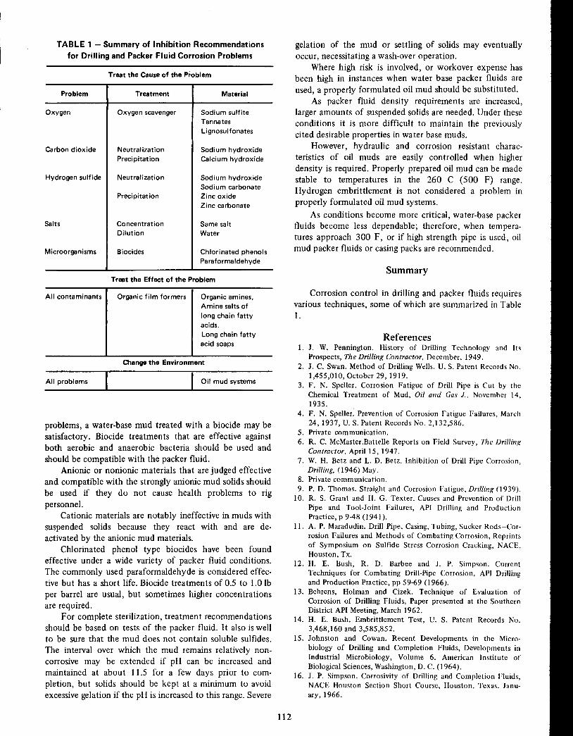
TABLE 1 - Summary of Inhibition Recommendations
for Drilling and Packer Fluid Corrosion Problems
Change the Environment
All problems 1 1 Oil mud systems
problems, a water-base mud treated with a biocide may besatisfactory. Biocide treatments that are effective againstboth aerobic and anaerobic bacteria should be used and
should be compatible with the packer fluid.Anionic or nonionic materials that are judged effective
and compatible with the strongly anionic mud solids shouldbe used if they do not cause health problems to rigpersonnel.
Cationic materials are notably ineffective in muds withsuspended solids because they react with and are deactivated by the anionic mud materials.
Chlorinated phenol type biocides have been foundeffective under a wide variety of packer fluid conditions.The commonly used paraformaldehyde is considered effective but has a short life. Biocide treatments of 0.5 to 1.0 Ib
per barrel are usual, but sometimes higher concentrationsare required.
For complete sterilization, treatment recommendationsshould be based on tests of the packer fluid. It also is wellto be sure that the mud does not contain soluble sulfides.
The interval over which the mud remains relatively noncorrosive may be extended if pH can be increased andmaintained at about 11.5 for a few days prior to completion, but solids should be kept at a minimum to avoidexcessive gelation if the pH is increased to this range. Severe
gelation of the mud or settling of solids may eventuallyoccur, necessitating a wash-over operation.
Where high risk is involved, or workover expense hasbeen high in instances when water base packer fluids areused, a properly formulated oil mud should be substituted.
As packer fluid density requirements are increased,larger amounts of suspended solids are needed. Under theseconditions it is more difficult to maintain the previouslycited desirable properties in water base muds.
However, hydraulic and corrosion resistant characteristics of oil muds are easily controlled when higherdensity is required. Properly prepared oil mud can be madestable to temperatures in the 260 C (500 F) range.Hydrogen embrittlement is not considered a problem inproperly formulated oil mud systems.
As conditions become more critical, water-base packerfluids become less dependable; therefore, when temperatures approach 300 F, or if high strength pipe is used, oilmud packer fluids or casing packs are recommended.
Summary
Corrosion control in drilling and packer fluids requiresvarious techniques, some of which are summarized in Table1.
References1. J. W. Pennington. History of Drilling Technology and Its
Prospects, The Drilling Contractor. December, 1949.2. J. C. Swan. Method of Drilling Wells, U. S. Patent Records No.
1,455,010, October 29,1919.3. F. N. SpeIler. Corrosion Fatigue of Drill Pipe is Cut by the
Chemical Treatment of Mud, Oil and Gas J.. November 14,1935.
4. F. N. SpeIler. Prevention of Corrosion Fatigue Failures, March24,1937, U. S. Patent Records No. 2,132,586.
5. Private communication.
6. R. C. McMaster .BatteIle Reports on Field Survey, The Drillinf(Contractor, April 15, 1947.
7. W. H. Betz and L. D. Betz. Inhibition of Drill Pipe Corrosion,Drilling, (1946) May.
8. Private communication.
9. P. D. Thomas. Straight and Corrosion Fatigue, Dri/linf( (1939).10. R. S. Grant and H. G. Texter. Causes and Prevention of Drill
Pipe and Tool-Joint Failures, API Drilling and ProductionPractice, p 9-48 (1941).
1I. A. P. Maradudin. Drill Pipe, Casing, Tubing, Sucker Rods~Corrosion Failures and Methods of Combating Corrosion, Reprintsof Symposium on Sulfide Stress Corrosion Cracking, NACE,Houston, Tx.
12. H. E. Bush, R. D. Barbee and J. P. Simpson. CurrentTechniques for Combating Drill-Pipe Corrosion, API Drillingand Production Practice, pp 59-69 (1966).
13. Behrens, Holman and Cizek. Technique of Evaluation ofCorrosion of Drilling Fluids, Paper presented at the SouthernDistrict API Meeting, March 1962.
14. H. E. Bush. Embrittlement Test, U. S. Patent Records No.3,468,160 and 3,585,852.
15. Johnston and Cowan. Recent Developments in the Microbiology of Drilling and Completion Fluids, Developments inIndustrial Microbiology, Volume 6. American Institute ofBiological Sciences, Washington, D. C. (1964).
16. J. P. Simpson. Corrosivity of Drilling and Completion Fluids,NACE Houston Section Short Course, Houston, Texas. January, 1966.
112
Material
Sodium sulfiteTannates
Lignosulfonates
Sodium hydroxideCalcium hydroxide
Sodium hydroxideSodium carbonateZinc oxideZinc carbonate
Same saltWater
Organic amines,Amine salts of
long chai n fattyacids.
Long chain fattyacid soaps
Chlorinated phenolsParaformaldehyde
Treatment
Organic film formers
Oxygen scavenger
Neutralization
Precipitation
Neutral ization
Precipitation
ConcentrationDilution
Biocides
Treat the Effect of the Problem
Treat the Cause of the Problem
Problem
All contaminants
Carbon dioxide
Oxygen
Hydrogen sulfide
Salts
Microorganisms

17. Barbee. Corrosion Control Important in Packer Fluids: CasingPacks, Petroleum Equipment. March-April, 1966.
18. J. P. Simpson and R. S. Andrews. Oil Mud Packs forCombatting Casing Corrosion, Mat. Pro.,' 5, No. 6 (1966) June.
19. Simpson and Barbee. Corrosivity of Water Base CompletionFluids, Mat. Pro., 6, No. 12 (1967) December.
20. W. C. Skelly and Kjellstrand. The Thermal Degradation ofModified Lignosulfonates in Drilling Mud, The A.P.I. Div.Prod., Houston, Texas, March 1966.
21. B. G. Chesser. Corrosivity of Chrome Treated Sodium Lignosulfonate Packer Fluid Systems, A.P.I. Div. Prod., Tyler, Texas,March 1968.
22. J. A. Clark and H. Sheridan. Experience with Plastic CoatedDrill Pipe, The Drilling Contractor, November-December, 1965.
23. A Survey of Corrosion Control in Drilling and Annular Fluids,NACE Publication 10168, NACE, Houston, Texas.
24. B. W. Bradley. Oxygen, Cause of Drill Pipe Corrosion, ThePetroleum Engineer, December, 1970.
25. F. E. Blount and E. S. Snavely. Use of High-Capability OxygenMeter in Corrosion Control, Proceedings NACE 25th Conference, 1969. NACE, Houston, Texas, pp 193-208.
26. K. E. Wattman. New Weapon Joins Battle to Extend Drill PipeLife, Drilling, August, 1963.
27. A. C. Perricone and B. G. Chesser. The Corrosive Aspects ofCopper Carbonate in Drilling Muds, Milchem Research TechnicalBulletin.
28. William H. Johnston, Memoranda. The Action of NascentHydrogen on Iron, Scribner's Monthly Magazine, May toOctober, 1874.
29. R. 1. McGlasson. Special Metallurgical Problems, Proc. U ofOkla. Corrosion Control Course, Norman, Okla. 1970. NACE,Houston, Texas.
30. J. P. Simpson. Stability and Corrosivity of Packer Fluids,Presented in a panel discussion on packer fluids at the 1968 APISouthwestern District Meeting, Tyler, Texas, March, 1968.
APPENDIX I
Characteristics of Packer Fluidsfor Casing-Casing or Casing-Tubing Annuli
Provide density as required to assist in maintaining thepacker seal and in preventing bursting or collapse of pipe.There should be no compacted settling of solids andsludging and top separation of liquid should be minimal.
Be fluid enough to permit placement in a small annulusor a good displacement in a large annulus.
Be stable at downhole conditions of temperature andpressure.
113
Be noncorrosive, Le., resist corrosion from oxygen,carbon dioxide, hydrogen sulfide, organic acids or bacteriathat might be present.
Because the packer fluid is designed as a non-communicating system, the primary consideration is to formulate afluid that is functional under the conditions listed.
The casing pack is defined as the fluid left in the casingformation annulus.
APPENDIX 2
Characteristics of Packer Fluidsfor External Casing
(in Addition to Those for Casing-Tubing Annulus)
Have very low filtration rate to avoid significant loss ofvolume or change in composition of the pack.
Be sufficiently gelled to prevent migration of fluidswithin the annulus.
Protect casing from corrosion by formation fluids.(Provide physical barrier and/or chemical resistance.)
BIBLIOGRAPHYSymposium on Sulfide Stress Corrosion. Corrosion, 8, No. 10,
325-360 (1952) Oct.D. R. Fincher. Corrosion Problems Associated With Sour Gas
Condensate Production, Corrosion, 15, No. 8, 413t-416t (1959)Aug.
D. W. Shannon and J. E. Boggs. Factors Affecting the Corrosion ofSteel by Oil-Brine-Hydrogen Sulfide Mixtures, Corrosion, IS, No.6, 299t-302t (1959) Nov.
C. M. Hudgins, J. E. Landers and W. D. Greathouse. CorrosionProblems in the Use of Dense Salt Solutions as Packer Fluids,Corrosion, 16, No. 11, 535t-538t (1960) Nov.
R. S. Ladley. Stress-Corrosion Cracking of High Strength OilCountry Tubular Goods, Corrosion, 16, No. 11, 539t-542t(1960) Nov.
M. F. Baldy. Sulfide Stress Cracking of Steels for API N-80 TubularProducts, Corrosion, 17, No. 11, 509t-513t (1961) Nov.
1. P. Simpson and R. S. Andrews. Oil Mud Packs for CombatingCasing Corrosion, Mat. Pro., 5, No. 6, 21-25 (1966) June.
B. J. Ramey and B. G. Price. Causes, Detection, Prevention: DrillPipe Corrosion Fatigue Failure, Mat. Pro., 5, No. 6, 86-88(1966) June.
B. W. Bradley. Oxygen-A Major Element in Drill Pipe Corrosion,Mat. Pro., 6, No. 12,40-43 (1967) Dec.
G. 1. Nunn and O. H. Haveman. Getty Oil's Experience With PackerFluids, Mat. Pro., 7, No. 12,37-38 (1968) Dec.

GEORGE B. HATCH*
Inhibitors for Potable Water
Potable waters vary widely in composition and corrosivity.
Some are extremely aggressive, while others cause neglibleattack, unfortunately the latter are a rather small minority.
Surface supplies generally approach saturation withrespect to dissolved oxygen. As a result, they usually arequite corrosive unless the water lays down a protective filmor deposit (i.e., unless it is naturally inhibitive).
Deep well supplies generally are essentially devoid ofdissolved oxygen and as a result practically noncorrosive.Unfortunately, absorption of oxygen is difficult to prevent,particularly when appreciable treatment (e.g., clarification,settling, etc.) is required prior to introduction into thedistribution system.
It follows that many potable water supplies requiretreatment in order to alleviate problems raised by corrosionof the distribution system.
The number of inhibitors available for treatment of
drinking water is drastically limited by potability considerations. Moderate pH elevation, calcium carbonate scale andlimited concentrations of silicates, polyphosphates and zincsalts are about the only inhibitors permissible for potableservice at this time. All of these have been known for a
number of years and have been investigated quite extensively, both alone and in combination. Levels of the permissibleinhibitors are considerably restricted by potability requirements.
Economics of TreatmentEconomic considerations frequently lead to even more
drastic limitation of treatment levels. The beneficial effects
of the treatment on the distribution system and the qualityof its effluent must be balanced against its cost.
Carrying capacity falls off long before corrosion products reduce the cross-sectional area of a water line
appreciably. Increased surface roughness, such as producedby relatively small scattered tubercules, suffices to interferewith flow quite markedly. Tuberculation which sufficed tolower the Williams-Hazen Friction Coefficient of a cast iron
main from 128 to 110 is shown in Figure 1. Thisphotograph shows a section of the line removed forinspection prior to recleaning to restore the needed carryingcapacity.
From an economic point of view, obstruction to flow isthe major problem raised by corrosion in a water distribu-
*Deceased. Formerly with Calgon Corp., Pittsburgh, Pa.
114
tion system. Increased pumping costs of $40 million a yearhave been estimated to result from obstruction of flow bycorrosion products. 1 The problem becomes increasinglyacute as increases in water consumption tax existingdistribution facilities.
Failure of piping as a result of corrosion on the waterside seldom is a problem in potable distribution systems.This contrasts with the situation encountered on most
other inhibitor applications where internal failures areperhaps the most serious manifestations of corrosion.Dearth of internal failures probably is a consequence of therather extensive use of heavy-wall, cast-iron pipe in municipal distribution service.
Corrosion of water heaters poses a much more expensive problem. Replacement costs have been estimated at$300 million a year.1 This problem generally is consideredto be one to be passed on to the individual consumer.Inhibitor levels are chosen for protection of the majordistribution system and treatment of the entire system atan inhibitor level sufficient to protect the individualconsumer's system-either hot or cold-seldom has been
FIGURE 1 - Tuberculation of cast iron water main whichreduced the WilliamlYHazen Friction Coefficient from 128 to110.

FIGURE 2 - Influence of dissolved copper on corrosion ofaluminum and zinc by Pittsburgh tap water.
attempted. Protection of these individual systems is left tothe owners.
Influence of Dissolved Oxygen
Unfortunately, the values for dissolved oxygenprobably the most important constituent from the corrosion standpoint-are not included among the data in Table1. Potable supplies generally fall in or are adjusted to a pH
range (i.e. 5-11), where depolarization of the cathodicallyliberated hydrogen is required to sustain appreciable corrosion. Even in oxygen saturated supplies, the corrosivity of awater cannot be calculated from its analysis. A rather roughqualitative estimate is about the best that can be made.
Dissolved oxygen does not render pure water particularly corrosive, at least at normal temperatures (i.e., 0-4OC).
However, additions of traces of sulfate or chloride (e.g.,0.55 mg/I) suffice to make it highly aggressive.4
Larson and coworkerss-7 have found that chlorides,sulfates and nitrates stimulate corrosion of iron in oxygen-
Characteristics of Potable Water
Potable waters of the United States vary quite widelyin composition. Dissolved solids range from about 20 mg/lto over 2 g/l. Over 100 public supplies exceeded 2 g/l totalsolids in 1962.2
Analyses of some of the different types of waterswhich serve as potable supplies in the United States areincluded in Table 1. These data were chosen from the com
pilations of Lohr and Love.3The first column of the table gives the composition of a
very soft water of low dissolved solids content, a type quitecommon along the Northwestern and Eastern seacosts.Natural soft supplies are not limited to low solids waters.For example, the water in Column 2, although low inhardness contains quite high levels of alkali metal, bicarbonates, sulfates and chlorides.
Data for a lime-soda softened effluent are given inColumn 3. The pH of this particular supply is higher thanusual because the softener effluent was not recarbonated.
Potable waters also include hard waters of highelectrolyte content as shown in Column 4, for example.The hard, acid-supply shown in Column 5 reflects contamination from coal mine drainage. It is rather unusual in thatthe pH generally is raised to at least five, even where noother measures are taken to alleviate attack.
The recommended maxima for drinking water2 areshown in the last column. When these values are exceeded,another supply, if available, is recommended. Unfortunate
ly, these recommended maxima are quite frequently exceeded and even the mandatory limits occasionally areexceeded (e.g., the fluoride contents of the waters inColumns 2 and 4).
systems usually leads the individual home owner to select
the alternative of more resistant and more expensivematerials. Some larger cities require that any auxiliarytreatment system be supervised and the levels thereofperiodically checked by qualified personnel.
Thus, there are two more or less discrete aspects of theproblem: Inhibitor treatment for the distribution systemand auxiliary protective measures for the consumer systems.
ALUMINUM(3003-H14)
0.5
COPPER CONC. Mg/I
~~-------~-------------,~/l,,,I'
20
50
o
10
Corrosion Products are the Problem
in Potable Water SystemsDeterioration of water quality is an additional major
consequence of corrosion in a potable distribution system.Although essentially a problem of consumer relations, itgenerally has priority over strictly economic considerations.En trainmen t of corrosion products with the result red andturbid water is a sure source of consumer complaints.Occasionally, the red water problem has been alleviated bymoderate elevation of pH. This tends to precipitate thehydrous ferric oxide before it can reach the consumer.Frequently this practice has been unsuccessful and evenwhere it has controlled red water successfully, it obviouslyhas been of no help in maintaining the carrying capacitiesof the mains. The products of corrosion attack are the mosttroublesome aspect of corrosion in the distribu tion system.They obstruct flow when they remain in the lines and causered water when they do not. The only satisfactory solutionis to inhibit the attack.
The consumer, in an effort to control corrosion of his
piping, may use an auxiliary inhibitor feed or maysubstitute more resistant materials than iron to handle the
water. Large installations such as apartments, office buildings, etc. generally find inhibition more economical. Thecost and attention required to maintain auxiliary inhibitor
ClCl~I
(J)(J)
g 0I- 100::r:t:}ws:
115

TABLE 1 - Compositions of Various Domestic Water Supplies
(Concentrations in mg/I)(1)
(2)(3)(4)(5)(6)low
SoftSoftHardDissolved
Highlime-SodaHighHardUSPHSConstituent
SolidsElectrolyteEffluentElectrolyteAcidMaxima
Silica (Si02)
5.7227.653 10-Iron (Fe)
0.10.050.070.080.380.3Manganese (Mn)
--0.00- 3.60.5Calcium (Ca)
1.44.033.0153.020.0-Magnesium (Mg)
0.81.60.794.019.0-Sodium (Na)
2.7462.013.2233.04.6-Potassium (K)
Bicarbonate (HC03)
8.0520.0-244.00-Carbonate (C03)
06.010.000-Caustic Alk. (OH)
007.000-Acidity (H2S04)
000074.0-Sulfate (S04)
2.5167.067.0540.0170.0250.0Chloride (Cl)
2.2288.05.8344.02.6250.0Fluoride (F)
01.80.11.80.26-1.7(
Nitrate (N03)
0.40.02.0- 045.0Total Hardness (CaC03)
7.016.086.0768.0228.0-Total Dis. Solids
22.01210.0156.01550.0306.0500.0pH
7.88.210.67.43.9-
(l)Limit is temperature dependent.
bearing water, while calcium, bicarbonate and hydroxidewere inhibitive. They suggested that the corrosivity ofair-saturated domestic waters depends on the ratio of
aggressive to inhibitive ions. Examination of Table 1 fromthis standpoint suggests pronounced differences in thecorrosivity of these domestic supplies.
Influence of pH
The pH affects both the type and velocity of theattack. It also influences the performance of inhibitorsagainst the attack as well as affecting deposit formation.
Differences of pH in the range of 5 to about 9.5 do notsignificantly affect the rate of attack of iron and steel bynonscaling, oxygen and calcium-bearing waters.8,9 Corrosivity with respect to ferrous metals falls off quite rapidlywith further elevation of the pH.
Materials Used in Water Systems
Distribution SystemsAlthough gray cast iron long has been the principal
material used for distribution lines, steel and ductile iron
are used to a lesser though growing extent. Protection ofthese ferrous metals is the primary aim of corrosion controlin the distribution system.
Lines fabricated from nonmetallic materials such as
concrete, asbestos cement and plastic are being used to anincreasing degree in distribution systems but they will beexcluded from the present discussion because they are notsubject to electrochemical corrosion. Further informationconcerning the current use of both the metallic and
116
l)
nonmetallic materials in this service is included in the paperby Wilson. 1 0
Copper and lead (in some of the older system s) serve aslead-ins to the consumer systems. Thus, they can affect thequality of the water delivered to the consumer.
Toxicity of Dissolved LeadDissolved lead is highly toxic. Consequen tly, it is of
concern to the supplier even when restricted to theconsumer's system. Although, lead is not commonly usednor should it be used-in modern water piping, it still maybe encountered in some older systems.
The magnitude of the dissolved lead problem is broughtout in a recent report of the Bureau of Water Hygeine, V.S.
Public Health Servicell which covered 989 supplies thatserviced 18.2 million people. Roughly 2% of these werefound to be consuming water with excessive concentrationsof lead (Le., over the U .S. Public Health Service's mandatory limitsl2) the source of which was attributed to leadpipes in the home or supply systems.
Consumer Systems
A rather wide range of metals is used in consumer'swater systems. Steel, galvanized iron, copper, bronze andred and yellow brass are among the more common. Lead,aluminum, monel and both ferritic and austenitic stainless
steels also may be encountered occasionally. Each of thesemetals, to a greater or lesser degree, adds its own particularcorrosion problems.
The manner in which the system is fabricated greatly

affects its susceptibility to attack. Care should be taken toavoid crevices, deposits, thread cuttings and miscellaneousdebris which can obstruct access of dissolved oxygen to themetal surface and thereby set up differential aeration cells.The latter are detrimental to all of the metals involved, but
especially to aluminum, monel and stainless ste~ls.Frequently, unfortunate combinations of different
metals in a single system cause severe galvanic corrosion.Direct couples of some of these different metals are a ratherobvious source of trouble and are particularly destructivewhere the area of the cathodic metal is large compared tothat of the anodic component.
Couples also may develop during operation of thesystem. Traces of metal dissolved from upstream portionsof the system frequently deposit on contact with moreactive components. The resultant couples can lead toserious attack of the more active metals. Relatively insignificant corrosion of the cathodic metal can dissolve amounts
sufficient to accelerate attack of the active component to apronounced degree. For example, even 0.1 mg/l ofdissolved copper markedly accelerated attack on zinc1 2 andaluminum as illustrated by the data in Figure 2.
Impingement attack of copper is a rather commonsource of trouble in some of the larger consumer systems(e.g., apartment and institutional buildings, hospitals, etc.).Among the more recent discussions of the problem arethose of Obrecht13 and Hatch 14. The difficulty oftenstems from an unfortunate choice of materials, because
copper is particularly susceptible to attack of this nature.Even under optimum conditions, flow velocities over 5
ft/sec should be avoided where copper is used. The presenceof an entrained second phase (e.g., air bubbles, suspendedsolids, etc.) reduces the allowable velocity even further.
Copper portions of circulating hot water systemsadjacent to the suction side of the circulating pump areparticularly susceptible to impingement attack becausedissolved air can separate from the water if pressurereduction is excessive. Air also may be pulled in throughleaky faucets. In either case it tends to promote impingement attack.
Figure 3 shows two sections of copper tubing from acirculating hot water system of a hospital which havesuffered severe impingement attack. Tubing was undersizedand the susultant excessive flow velocity led to the attack.
Copper also may suffer localized attack (Le., pitting)which does not involve excessive flow velocities. It is
fortunate that pitting of this type seldom is encounteredbecause its causes are not fully understood. Figure 4 showsan example of such attack. The bright spots in the pit at theleft are caused by reflections from relatively large crystalsof cuprous oxide at the bottom of the pit. Well formedcrystals of cuprous oxide such as this generally areassociated with this type of localized attack on copper.
Influence of TemperatureWater temperatures in the distribution system may
range from just above freezing to around 30 C. Temperatures of almost 100 C frequently are encountered indomestic hot water service despite admonitions to limit
117
FIGURE 3 - Copper tubing sections from circulating hotwater system which suffered severe impingement attack.
FIGURE 4 - Pitting of copper tubing in domestic service.

FIGURE 5 - Pitted galvanized hot water tank which failedweeks' service in Pittsburgh water at 82 C (180 F).
temperatures to 60 C to avoid excessive corrosion. Theinfluence of operating conditions of the corrosion in hotwater systems has been discussed by Shuldener.1 5
In domestic service the corrosion rate increases steadilyas the temperature is raised. The maximum in the corrosionrate-vs-temperature curve is displaced at higher temperatures as a result of higher oxygen solubility levels in thesepressurized systems.
Excessive temperatures are particularly detrimental togalvanized hot water tanks where potential reversals between zinc and steel may occur at temperatures above 60 Cto aggravate localized attack on the stee1.16 Actually,galvanically accelerated attack on the steel base can evenoccur in cold water. The intermediate zinc-iron alloy layerformed during hot galvanizing is reported to be cathodic toboth zinc and steel in either hot or cold oxygen-bearingwater. 1 7
Pits revealed after wire brushing to remove tuberculesin a bottom-fired galvanized hot water tank which failedafter 81 weeks of a test in Pittsburgh tap water at 82 C(180 F) are shown in Figure 5. The water involved was
118
essentially a dilute solution of calcium sulfate whichcontained a moderate amount of chloride and was ratherlow in bicarbonate. The hardness showed a seasonal
variation from about 35 to 200 mg CaC03/1 while the pHaveraged 6.7.
Inhibition of Potable Water
pH Elevation
pH elevation alone is not frequently relied on forcorrosion protection. Yet, its inhibitive action is pertinent,because its properties frequently persist and substantiallyalter the nature of the protection obtained from otherinhibitors. A sufficient increase in pH (e .g., 10 to 11) willinhibit the corrosion of iron and steel quite effectively.However, use of this method is restricted to relatively softwaters where excessive depostion of calcium carbonatescale does not pose a problem.
Effluents of lime-soda softeners are inherently welladapted for corrosion control by this means. Calciumcarbonate depositon from such an effluent (i.e., afterprecipitation) can be prevented quite simply by treatmentwith 0.25 to 0.5 mg/l polyphosphate. The lime-sodasoftened supply depicted in Column 3 of Table I is anexample of water where this type of corrosion control isinvolved.
Harder waters (Le., 100 mg/l CaC03) cannot bestabilized at such elevated pH levels (i.e., 10 to 11) by thepolyphosphates. Thus, pH elevation for corrosion control isnot applicable to waters of this type.
The chief inhibitive function of elevated pH is itsmaintenance of a protective oxide film. Ferrous ionsformed during incipient stages of attack are oxidizedrapidly and precipitated in situ by the high pH, oxygenbearing medium.
Increasing the pH to intermediate levels (e.g., 7.2 to9.5) serves primarily to localize attack. Corrosion of steel isessentially uniformly distributed in oxygen bearing potablewaters at pH levels of 7 or less. As the pH rises appreciablyabove this level however, more of the corrosion productsadhere to the metal surface and the attack begins tolocalize. While localized corrosion alleviates red water
somewhat, it aggravates obstruction of flow considerably.No pronounced drop in volume of metal consumed
accompanies the early stages of pH elevation because theincreased attack on the anodes roughly balances the
reduction of the anodic area. Not until the pH reachesabout 9.5 does this balance tip appreciably and the totalattack start to fall off significantly. A pH of 10 or aboveusually is required before a satisfactory degree of inhibitionis attained.
The most serious objection to control by pH elevationis localization of attack produced at intermediate levels
which is characterized by severe tuberculation. While pHlevels required for adequate protection frequently areconsidered excessive for human consumption, this objection, though perhaps more valid from an aesthetic than aphysiological point of view, is none the less generallydecisive.

Inhibition is often sensitive to electrolyte concentration, a characteristic common to most passivators.
pH levels sufficiently high to afford adequate protection for iron and steel are excessive for galvanizing,aluminum and yellow brass.
Controlled Scale
Elevation of the pH of a hard bicarbonate water willconvert the problem from one of the corrosion to one ofscale. If proper control can be established so that these twotendencies can be balanced, corrosion can be controlled
satisfactorily without excessive deposition of calcium car
bonate scale. Most natural or lime-soda softened suppliescontain sufficient calcium to make scale control feasible.
Baylis pioneered this system of corrosion control over
50 years ago at J ackson, Mississippi 18 and developed itfurther at Baltimore, Maryland.19,2 0 His aim was to adjustthe pH to a point at which the tendencies to corrode and to
encrust were at a minimum. This generally requires thewater to be very slightly encrustant-just sufficientlysupersaturated to lay down and maintain a uniform, thin,
"egg-shell" coating of calcium carbonate to isolate themetal surface effectively from the corrosive action of thewater.
The illusory simplicity of the process and its apparentbasis in elementary physical chemical principles renders itexpecially attractive. Means for the attainment and mainte
nance of the desired uniform "egg-shell" coating haveprovided a subject for continual research for the past 50years.
Control of the degree of saturation with respect tocalcium carbonate can be calculated or determined experimentally.
The experimental de terminations consist of contactingthe water with an extended surface of calcium carbonate
and subsequent determination of the resultant change in pHor alkalinity. In the batch procedure, the water is shakenwith finely divided calcium carbonate. A continuous
stability indicator suggested by Enslow21 is afforded bypassing a stream of the water through a column filled withcalcium carbonate encrusted f1lter sand and then deter
mining the change in pH and/or alkalinity. Determination
DETERMINATION OF pH SATURATION BY LANGELIEII" F'OIlMULACOLUMN 2
COLUMN aCOLUIIN • COLUIIN ,PIVOT LINE , ea.pIli ALR.7.5 --, -,r: ,t2.5
'1!
710-l.-lE"" 1t.1 .t
'f
11.0a
'.5 -l •10.5 •5
,6
10.0•
7'.0 -l 7 •• ,9 '.5 toID
u-..:l '.015I'
1010 '.5
155.0 -l aDaD '.040
4.5 -l 507.5
6070...::j
f- 7.0104.0 -1 90
".~ r1.5""1
150'.0
100'.5
a.o -laoo5.0400
La
t.O
1·1
I.t
90 C;;;j>
.E:B:.- ~
Et•.u:: ~o'c'" .J:--'...
+-_ .0..-
,~':::r:t: 60'C
:1
qi~~.t+
':1'
40·C .+--
HO'C'·.1''''- .....• -
--- -.•.... :" •. B .....
GRlIPH liNO NOMDGRAM F'OA
COLUIIN 1
_~~:~f.--<0 ., __
.:+-I- _: -' .:. . j30 t I";
. .~t··. ~ .. J.' .-- - - +-- - -+
o 100 200 300 '00 500 600 700 .00TOTAL DISSOLVED SOLIDS IN PARTS PER MILLION
GRa'H AND NOMOGAAM FOR OETERMINATlON OF' pH SATURATION IY 000"" ~ 4 5LANGELI(A'S FORMULA (APPLICABLE WITHIN pH RANGE 7.0" ,.5) •DATA REQUIRED rOR OETERMINING pH SATURATION,
(a.) TOTAL AlKAllNlTY1AS PARTS PEA MILLION OF' CCLC'O)(b) CALCIUM IN PARTS PER MILLION.
(e) TOTAL DISSOLVED SOLlOS,IN PARTS PER MILLION.(d) TEMPERATURE, IN DEGREES CENTIGRADE, AT WHICH pH SATURATION IS OUIREO.IMSYJlUCrrONS FOR USING CHART
Ca.) RNOWING TEMPERATURE AND TOTAL DISSOLVED SOUO" "NO TEMPERATURE a TOTAL SOLID' CONSTANT ON COL. 1
Cbi ALIGN fMIS CONSTANT WITH GIVEN VALUE OF CALCIUM ON COL.3 OF CHART. THEN LOCATt POINT OH COL. 2 0' CHAlItT (PIVOT .LINE)(c.) ALIGN THIS POINT ON PIVOT LINE WITH GIVE" ALICALINITY ON COL. 5. READ pt-( SATURATION OH COLUMN ••
SATURATION INOE~ IS pH ACTUAL MINUS pH SATURATION. E.G. -- pH ACTUAL. pH "TURATlON. SATURATION INOE~. GRAPH AND NOMOGR ••• FOR DETERMINATION 0' pH7.6 '.1 -0.5 (CORROSIVE) SATURATION ANOLANGEUER'S SATURATION INOr.
I.' r •• + 0.6 (SCALE FORMING) IASEO ON ARTICLE IN OCT 'US,ISSUE O'AMERleAIlWATER wORR' ASSOCIATION JOURNAL AND LATERCORRECTIONS "0'' lAOLES 2 AHD 4. ~"E~AlIt[O '0.CHARLES P. HOOYER OF THE COLU"'UI,OHIO. WATI"
SOFTENING AND PURIFleATlON I'\.ANT •• ME. RILL
L. RIEHL S(PT. IT. In ••
FIGURE 6 - langelier's formula. Reprinted by permission from Water Supply and Treatment, NinthEdition. By Merrill l. Riehl. National lime Association. 400 Brandywine St., N.W.• Washington D.e.20016. Per copy, $2.15.
119

of the change in alkalinity affords a measure of the amountof deposition that can occur, a value which cannot beascertained from the change in pH.
Langelier described a procedure for calcualtion of thepH of saturation from the calcium, total alkalinity anddissolved soldis contents of the water.22 He termed the
difference between this value and the actual pH theCalcium Carbonate Saturation Index. It also is frequentlyreferred to as the Langelier Index.
Sat. Index = pH - pHs
pHs = (pK2' - pKs') + pCa = pAIkwhere,
pHs is the saturation pH;pK2, pKs, pCa and pAlk are respectively the logs of the
reciprocals of the second dissociation constant ofcarbonic acid, of the solubility product of calciumcarbonate, of the molal concentration of calcium and
the equivalent concentration of the total alkalinity.
A positive value of the index shows the water to besupersaturated with respect to calcium carbonate; a negative value shows it to be undersaturated. A nomograph toassist in calculating the Saturation Index is shown in Figure6.
Salinity corrections are included in the (pK2' - pKs')values given by Langelier. They were revised later byPowell, Bacon and Knoedler23 on the basis of moreaccurate values for the dissociation of carbonic acid.
The Langelier Index shows whether or not calciumcarbonate can precipitate, but it does not indicate howmuch can precipitate. In this respect the experimentalprocedure previously discussed is advantageous.
An empirical saturation index which provides anindication of the amount of deposition which may occurhas been proposed by Ryznar:24
Ryznar Index = 2pHs - pH25 C.
Six is considered the optimum value for this index. Calciumcarbonate scale deposition increases progressively as theindex drops below 6, while corrosion reputedly increases asit rises above 6.
The Ryznar Index has not enjoyed as wide applicationto potable supplies as that of Langelier. Its empirical naturelacks the appeal of the latter which is firmly based onequilibrium solubility.
Calcium carbonate scale sometimes fails to provide thedesired protection in spite of careful control of the degreeof saturation. The calcium carbonate fails to form the
desired thin, uniform and inpervious barrier layer. Instead,the deposits are porous and permit attack of the underlyingmetal to continue.
Evans25 has suggested that calcium carbonate deposited on cathodic areas as a result of the locally increased pHis of a different and more protective form than thatprecipitated spontaneously from a supersaturated solution.
Stumm26,27 considers calcium carbonate to be an
120
effective inhibitor when anodic areas are sufficiently small
that they can be blocked by deposits. Conversely, it doesnot prove very effective when anodic areas are too large tobe blocked. He believes the deposits form initially oncathodic areas, but later extend over into and thus constrictthe anodic areas. The latter can be blocked effectively inthis manner only if they are sufficiently small.
Stumm notes that as the pH rises, the anodic spotsbecome larger but fewer (i.e., in range of pH 7 to 9.5). As aresult, calcium carbonate which precipitates at pH 7 to 7.4from hard, high-bicarbonate waters affords more effective
protection than that which precipitates at higher pH levelsfrom soft, low alkalinity waters.
The relative number and size of the anodic areas is
essentially a characteristic of pH. Localization of attack onelevation of pH occurs in calcium· free as well as incalcium-bearing waters, so it cannot be attributed tocalcium carbonate. Yet, it does limit considerably theoptimum range for inhibition with calcium carbonate scale.
While one might gather from the preceding discussionthat calcium carbonate scale cannot provide adequateprotection at pH levels much above 7.4, this is not alwaysthe case. Quite a few applications at pH levels of 8 or aboveappear to have been successful. The situation suggests thatadditional factors not yet considered are involved.
The rate of deposition of the calcium carbonate is acritical factor with respect to the formation of the desiredthin, impervious, protective deposit. Too rapid formationleads to porous, poorly protective deposits. In general therate of deposition increases with the supersaturation, but anumber of other factors is involved.
Supersaturated calcium carbonate solutions frequent-ly are quite stable in the absence of material which canserve as nuclei to initiate the depositon. While calciumcarbonate provides such nuclei, this is not particularlyhelpful in providing uniform surface coverage. Stllmper2 ~
found that a number of other solid surfaces, particularlyferric oxide, also served as nuclei and thus catalyzed thedeposition. On the other hand, zinc salts28 and variuus
tannins and lignin derivatives retard carbonate depositon tusome extent. Polyphosphates can stabilize calcium carbonate supersaturation to such a degree that calculatiunsbased on normal solubility considerations become totallyinapplicable in their presence.2 9
Obviously, the degree of supersaturation is not the onlyfactor involved in the attainment of a thin, uniform,protective calcium carbonate scale.
Use of Silicates
Silicates have been used for many years to alleviateattack on ferrous and nonferrous metals. Systematic investigations of the influence of silicates on cOffusion were madein the early twenties by Speller30 and Tex ter3 I in thiscountry and by Thresh32 in England. They recommendedits use for corrosion control in potable systems.
Dosages suggested by these early investigators were aminimum of 8 mg/I as silica during the establishment ofprotection (approximately 3 to 4 weeks) and a minimum of
4 mg/I silica for subsequent maintenance of protection.

These recommendations have not been altered appreciably
in the succeeding 50 years.Solutions of 40 to 42° Baume of a highly siliceous
silicate (l Na2 0: 3.3 Si02) generally are recommended forcorrosion control. However, in acid waters, a more alkalinesilicate is often used (e.g., I Na20:2 Si02). Very slowly
soluble glasses with a ratio of I Na2 0:3.3 Si02 occasionallyhave been used to automatically dispense the low levelsneeded for small systems (e.g., consumer).33 These glassesare incompletely soluble and leave a residue.
The silica content of a water usually is not taken into
account in setting the dosage rate because as a rule most ofthe naturally occurring silica is inactive for inhibitivepurposes. Analytical procedures are available to distinguishbetween the more chemically reactive, "soluble" silica andthe more inert collodial silica. They are used occasionally in
determining the desired silica feed.pH levels in the range of 8 to 9.5 generally have been
maintained in conjunction with silicate treatment. There
appear to be few data available to support this choice. Insome cases it seems to reflect an attempt to combine the
protective action of calcium carbonate scale with that ofthe silicates. The results of Wood, Beecher and Lawrence34indicate silicate inhibition to be more effective at pH 7 than
at 8.6, but their data do not appear to have been appliedvery extensively to the potable water field.
Silicates afford good protection to many nonferrousmetals used in potable systems. In fact, some of the earlierapplications were initiated for this purpose-for control oflead pick_up.32 and for the protection of galvanizing.3oProtection of iron and steel proved an added benefit.
Silicates give good protection to copper alloys. Theyhave proved very effective for protecting yellow brassagainst dezincification.3 5,36 Silicates also are good inhibitors for aluminum, although the levels for this purpose arehigller than normally used in potable service.
Lehrman and Shuldener investigated the nature of theprotective film formed by the silicates on black iron,galvanized iron and yellow brass.3 7 They found the film toconsist essentially of amorphous silica and the existence ofsolid corrosion products a prerequisite for silica adsorption.They found that zinc hydroxide took up the silica bychemisorption while the mechanism involved in the case ofiron and copper was somewhat uncertain. Adsorption ofsilica ceases when formation of corrosion products stops,with the result that the mm does not continue to build
up - it is self-limiting.Although silicates have been used for many years in
municipal systems, their application remains quite limited.They are commonly used in consumer systems. Theseapplications have been discussed by Stericker38 and morerecently by Shuldener and Sussman.39
The latter stress the importance of system design andmaterials used in fabrication as factors influencing the
protection afforded by silicates. They particularly stress thedesirability of adequate temperature regulation in hot watersystems and a maximum of 60 C. This appears to be ofprime importance for good protection with the silicatetre atm en t.
121
In spite of the long-time use of silicates for corrosioncontrol, much remains to be established concerning thevarious requirements for optimum protection.
Function of PolyphosphatesThe inhibitive properties of the polyphosphates are
discussed elsewhere in conjunction with cooling waterinhibitors, consequently, they will be reviewed briefly here.Only the factors particularly pertinent to potable systemswill receive attention.
Polyphosphates frequently have been used for corrosion control in potable distribution systems during the past30 years. Levels up to 10 mg/l (e.g., after main cleaning) arenot objectionable. However, dosages normally range from0.5 to I mg/l for larger cities to 2 to 5 mg/l for smallertowns with extended distribution systems.
While these suffice for protection of the distributionsystems, the full 10 mg/l is needed for protection ofconsumer systems, particularly hot water piping.
The differences in dosage requirements stem largelyfrom the relative rates of supply of inhibitor to the metalsurface in the different types of systems. Because the rateof protective film formation by polyphosphates is afunction of the rate of supply of inhibitor to the metalsurface, it depends on the amount of water flowing over thesurface as well as the concentration of inhibitor in the
water. The character of the flow also is an important factor.Turbulent flow obviously brings much more of the waterhence inhibitor-into contact with pipe walls than doesflow of a streamlined, laminar character.
The critical velocity for the incidence of turbulence
varies inversely as the diameter of the pipe. Consequently, amuch lower linear velocity suffices for the development ofturbulence in a relatively large diameter distribution linethan in a pipe of small diameter such as is used in domesticservice.
Prevention of red water is one of the major objectivesof corrosion control in potable systems. Polyphosphates
play a dual role in alleviation of the red water problembecause they can stabilize dissolved iron in the supply andinhibit the pickup of iron in the distribution system (i.e.,from corrosion). The two processes rely on two distinct andessentially independent properties of polyphosphates.
Stabilization of dissolved iron requires the presence of
the polyphosphate while the iron is in true solution.4o Inpractice, this means the presence of the polyphosphatebefore the iron-bearing water is exposed to air.
A ratio of l.l-sodium phosphate glass (Le., 1.1 Na2 0: 1P2 05) to iron of 2: I by weigllt is required for thestabilization. Higller ratios fur tlle r enhance protectionagainst precipitation. The ferrous polyphosphate complexwhich forms oxidizes very readily on contact with air. Theferric polyphosphate complex forms a white collodialdispersion, which also helps control the red water problem.
Prevention of red water caused by corrosion is primarily due to inhibition of the attack, because only smallamounts of iron will be stabilized in the effluent.
The optimum pH to control corrosion of ferrous metalswith polyphosphate is from 5 to 7. Althougll, protection

deteriorates if the pH falls either appreciably above orbelow these limits, the upper limit often is ignored in
potable water treatment. While some advantages of thetreatment may be felt at higher pH levels, the full benefit ofthe polyphosphate cannot be expected much above pH7.41
The deleterious results of excessive pH is not due solelyto decreased solubility of the calcium salts of these
phosphates because inhibition falls off at pH levels muchabove 7 even when no precipitation is involved. The mmgets lighter and less protective at the higher pH levels andappears to shift from the relatively thick electrodepositedprotective film to the much lighter "adsorbed" film whichserves to inactivate surfaces for the relief of calcium
carbona te supersaturation. 42pH levels above 7 are particularly deleterious to
maintenance of the carrying capacities of the lines. Asmentioned earlier, localized attack, with the attendant
formation of pits and tubercules, starts when pH risesappreciably above 7. The presence of polyphosphate doesnot alter the form of any attack which may take place in its
presence-it remains characteristic of the pH. This, coupledwith general deterioration of the inhibition, renders thesehigher pH levels particularly deleterious where maintenanceof carrying capacity is a major problem. Generally it is oneof the primary aims of the corrosion control program.
After Effects of Mechanical Cleaning. Many older watermains require mechanical cleaning to restore their carryingcapacity. When a mechanical scraper is run through thelines to remove tubercules and old deposits of corrosionproducts and/or scale the cleaning leaves a bare metalsurface which is very susceptible to attack.
The resultant red water problems can be extremelysevere unless adequate corrosion control measures aretaken. Moreover, the capacity of the freshly cleaned linewill deteriorate rapidly unless the corrosion is quicklybrought under control, so the untimate utility of the entirecleaning program depends on adequate control of subsequent corrosion. Polyphosphates may be used to advantagebefore, during and after mechanical cleaning.
Because treatment of the water with polyphosphateprior to mechanical cleaning softens calcareous portions ofthe deposit along with some of the less tightly bound ironoxides, the subsequent mechanical cleaning is facilitated.
I:'ch~lvely high dosages of polyphosphates (e.g., 25 to100 mgiJ) frequently are used in water used to push thescraper through the lines. Polyphosphates serve a dual rolein this 3.pplication: They help disperse and prevent settlingof material removed by the scraper and aid in its removalduring subsequent flushing and secondly, they rapidlyestablish protection of freshly bared metal surfaces.
Polyphosphate feed rates should be held at 20 to 40mg/I for a day after cleaning. Subsequently, they may belowered in a stepwise fashion, preferably to 10 mg/l for aweek or so, then to 5 mg/I for roughly a month and finallyto the normal operating level. The latter will depend on thesize and extent of the particular system.
Where very soft waters are involved, care should betaken in selecting the m ain cleaning dosages so that the
122
polyphosphates: calcium weight ratio does not exceed the5: 1 maximum for protective film formation.
Polyphosphate inhibition is quite sensitive to dissolvedcopper, which apparently passes through the poly phosphatefilm and plates out on the underlying iron and steel. Thecathodic surface of the resultant galvanic cell appears to beinaccessible to the inhibitor.
Particular care should be taken when polyphosphatesare used for corrosion control that soluble copper used tocontrol biological growths in reservoirs, etc. is removedbefore the water enters the distribution system. Redeposition of copper picked up in the system on the more anodiccomponents is seldom the problem in once-through operation that it is in a distribution system.
Effects on Nonferrous Metals. Polyphosphates are butmildly inhibitive to aluminum, lead and copper or itsalloys-much less effective than they are for iron, steel orzinc. Attack on aluminum in potable supplies frequently isthe result of dissolved copper or excessive pH, neither ofwhich is alleviated effectively by the polyphosphates.Polyphosphates reduce attack on lead, but not as effective
ly as the basic lead carbonate which forms at pH 7 orabove.43 It should be noted that lead sulfate is neither
sufficiently insoluble nor adherent to afford adequateprotection against lead pickup.4 3
Polyphosphates can be applied to small consumersystems where the cost of proportioning feed equipmentwould be excessive, by passing the water through a bed ofgranular, slowly soluble phosphate glass (e.g .. a sodiumcalcium polyphosphate).44
Polyphosphate-Zinc
The use of zinc salts with the polyphosphates markedlyaccelerates the establishment of protection.4o,4 5,46, Filmrepair also is accelerated by zinc which may be incorporated in the phosphate glass or may be fed separately as asoluble salt. The nature of the anion in the la tter casc in notcritical.
The general nature of the inhibition is not affcctedappreciably by the presence of the zinc. Conditions for theinhibition are essentially unaltered. For examplc, optimumpH remains at 5 to 7 and calcium requirements rcmainunchanged.
In cases where bettcr protection is not req uircd, tilC
general improvement in inhibition pcrmits main tenance ofthe same degree of protection with a lower inhibitor fccd.Kleber47 reports a case where I mg/I of a zinc-bcaringphosphate glass (8% Zn) gave results comparable to thoscobtained with 5 mg/l of the I.l-sodium phosphate glass. Inother cases, feed reductions of 50 to 65% are quitecommon.
Optimum zinc and polyphosphate dosages are somewhat interdependent. Higher zinc levels permit lowerpolyphosphate levels and vice versa. However, zinc dosagesgenerally are fixed at a definite percentage (i.e., between l)
and 10%) of the polyphosphate feed. Thus, the normaloperating level of zinc is well below the allowable limit (5
mg/l) for a potable supply? In fact, it leaves plenty of

room for temporarily increasing the feed rate, when evenfaster establishment of protection is needed.
The more rapid establishment of protection affordedby the zinc facilities control of red water in dead-end areas,where flow is almost negligible for extended times. The
frequent flushings and low continuous bleed-offs requiredfor adequate control of red water with polyphosphate alonein the more pronounced dead-end areas are largely eliminated with the polyphosphate-zinc treatment. This andother practical applications of the zinc-bearing polyphosphates in potable waters are discussed by Kleber47 and byPowers, Cahalan and Zalfa.48
Monie and Scales49 reported using zinc-bearing phosphate glass in an 8-in transmission line during cleaning andfor two weeks thereafter to assure rapid attainment ofprotection. They used zinc-bearing phosphate in amountsequivalent to 25 mg/l of line capacity in the water used todrive the scraper through the line and a 13 mg/l phosphateglass mixture which contained 4.6% zinc was fed for twoweeks after the cleaning. I. I-Sodium phosphate glass wasused for subsequent maintenance of protection, the dosageof which was lowered gradually to 3.5 mg/l and held at thislevel.
The cleaning raised the Williams-Hazen Friction Coefficient of the 8-in line from 50 to 55 to 122 (COL). Fouryears later the coefficient was 120.47 The condition of theline before and 4 years after cleaning is shown in Figure7.47
Application of zinc-bearing glasses to potable watersformerly was hindered by their rather slow solution rate.
This difficulty has been alleviated by the development of amore rapidly soluble zinc-bearing phosphate glass (Le., 4Na20' ZnO' 3P20S)'SO
SummaryOptimum conditions for corrosion control with poly
phosphates or polyphosphate-zinc combinations have become well established during the past 30 years, yet, theyfrequently are ignored in potable water applications.Treatment generally consists of simple addition of theinhibitor. Little attempt is made to adjust the pH levelsmost favorable for protection with the result that manyoperators fail to take full advantage of the potentialities ofthe inhibitor treatment.
Lack of toxicity at effective concentration levels
renders polyphosphate and polyphosphate-zinc particularlyattractive for corrosion control in potable water systems.
Not the least reason for their use is their effectiveness
at low concentrations, which makes them economicallyattractive for treating the large volumes of water involved inmunicipal systems.
Other CombinationsVarious other combinations of inhibitors have been
tested in potable service.
FIGURE 7 - Section of water main showing the influence of cleaning and subsequent inhibitortreatment. (Section at the left was removed prior to cleaning and shows the heavy tuberculation whichexisted. Section at the right was removed 4 years after mechanical cleaning and shows the influence ofthe polyphosphate-zinc treatment in controlling corrosion and tuberculation.) (Photograph Courtesyof Calgon Corp.)
123

The use of silicates along with the polyphosphates was
proposed by Speller.S 1 Silicates were used at a number ofArmy camps during the early forties with inconsistentresults. pH levels in these applications generally were toohigh for satisfactory development of the inhibitive potentialities of the polyphosphate.
Current use of silicate-polyphosphate mixtures islargely restricted to applications where the individual
'1erties of each of the components are needed. For~,,,ple, silicate may be used in soft, low pH waters to
,,:ol1trol copper pickup and staining, along with polyphosphates to control corrosion of iron and steel. The mixturesshow little indication of other than a strictly additivebehavior.
Quite recently, Murrays 2 described a mixture of zinc,sulfonate and orthophosphate for control of corrosion inpotable water systems. He used a ratio of 3 moles zincsulfate to 2 each of sulfamic acid and monosodium
orthosphate. Application of 10 to 15 mg/l of this mixture(Le., 2 to 3 mg zinc/l) was recommended during establishment of protection. Subsequently, the feed rate wasdropped to 5 mg/l (Le., 1 mg In/l). The pH of the watershould be held in the range 5.0 to 8.4. Although calciumcarbonate deposition interferes with the p~otection, itsdepositon can be avoided by application of 0.5 to 2 mg/lpolyphospha te.
Murrays 2 considers the protective mm deposited bythis mixture to consist of zinc orthophosphate. He indicated that the sulfamate serves to bind chlorine as achloramine and that this aids in the maintenance of
disinfection throughout a system.Although applications of the zinc-sulfamate
orthophosphate mixture appear to have been quite limitedso far (1970), results which have been reported lookpromising. Valid assessment of the utility of this inhibitivemixture must await further evaluation of its performanceand scope of applicability.
Environmental ConsiderationsSome corrosion inhibitors used in potable supplies
(e.g., zinc and phosphates) are considered to be environ·mental pollutants. Because much of this water eventuallypasses through sanitary sewage systems and joins surfacesupplies, this feature warrants consideration.
linc is one of the more abundant trace elements
required for mammalian development. Although levels upto 5 mg/l are permitted in potable waters, zinc is quitetoxic to various species of fish at levels of 1 mg/l or less.s 3
linc levels of this order (Le. 1 mg/l) are maintained
during normal operation with the zinc-sulfamateorthophosphate inhibitor, while slightly higher concentrations (Le., 2 to 3 mg/I) are used during establishment of
protection.s 2 Because zinc is quite readily adsorbed oncalcium carbonate,S 3 silt, etc. it appears doubtful that it
would survive passage through a sewage treatment plant.linc also is introduced with the polyphosphate-zinc
treatment, but at a rather low level (Le., 0.1 to 0.4 mg/lunder normal operation). While polyphosphate zinc used inconjunction with main cleaning involves temporarily high
124
levels of zinc, it generally is restricted to limited portions ofa system at anyone time. Consequently, the zinc contentof the sewage as a whole will not be raised excessively.
Phosphates introduced by inhibitors can be removed bysuitable operation of a sewage plant. Such steps should betaken in any event to take care of the phosphatesintroduced from other sources (e.g., human wastes, etc.).Phosphates can be precipitated with lime, alum or iron saltsor adsorbed on activated alumina or on activated sludgefloc.s 4
References1. Lichtenstein, S. The Many Faces of Corrosion. Tech. News.
Nat. Bur. Stand., U.S. Dept. of Commerce. STR-3454, Oct.1966. Materials Protection, 6,29 (1967) ApriL
2. Public Health Service Drinking Water Standards-1962. PublicHealth Service PubL No. 956,
3. Lohr, E. W. and Love, S. K. The Industrial Utility of PublicWater Supplies in the United States-Parts I & 11. GeologicalSurvey Water Supply Papers 1299 & 1300 (1952).
4. Hatch, G. B. and Rice, O. Influence of Water Composition onthe Corrosion of SteeL J. A WWA, 51, 719-727 (1959) June.
5. Larson, T. E. and King, R. M. Corrosion by Water at low FlowVelocity.J. A WWA, 46, 1-9 (1954) Jan.
6. Skold, R. V. and Larson, T. E. Measurement of the Instantaneous Corrosion Rate by Means of Polarization Data. Corrosion,13, 139t-142t (1957) Feb.
7. Larson, T. E. and Skold, R. V. Laboratory Studies RelatingMineral Quality of Water to Corrsoion of Steel and Cast Iron.Corrosion, 14, 285t-288t (1958) June.
8. Whitman, G. W., Russell, R. P., and Altieri, V. J. Effect ofHydrogen Ion Concentration on the Submerged Corrosion ofSteel. Ind. Eng. Chem., 16, 665 (1924).
9. Eliassen, R., Pereda, C., Romeo, A. J., and Skrinde, R. T.Effects of pH and Velocity on Corrosion of Steel Water Pipes.J. A WWA, 48, 1005-1017 (1956) Aug.
10. Wilson, H. E. Performance of Construction Materials forDomestic Water Piping Systems. Mat. Pro.. 7,24-28 (1968) Jan.
11. Report of Bur. of Water Hygiene, U.S. Public Health Service.Summarized in Chem. & Eng. News, 48, (No. 35), 10 (1970)Aug. 24.
12. Kenworthy, L. The Problem of Copper and Galvanized Iron inthe Same Water System. J. Inst. Metals (Brit.), 69, 67 (1943).
13. Obrecht, M. F. and Quill, L. L. How Temperature and VelocityAffect Corrosion of Copper and Copper Alloys. Heating, Piping& Air Cond., 165-169, Jan. 1960.
14. Hatch, G. B. Unusual Cases of Copper Corrosion. J. A WWA, 53,1417-1428 (1961) Nov.
15. Shuldener, H. L. Effect of Operating Conditions on Corrosionof Hot Water Piping in Buildings. Corrosion, 10, 85-90 (1954)Mar.
16. Schikorr, G. Trans. Electrochem. Soc., 66, 212(1939).17. Britton, S. C. The Resistance of Galvanized Iron to Corrosion
by Domestic Water Supplies. J. Soc. Chem. Ind., 55, (2), 19T(1936).
18. Baylis, J. R. Eng. News-Record, 80, 364, Feb. 21, 1918.19. Baylis,1. R. The Solution of Corrosion and Coagulation Prob
lems at Montebello Filters, Baltimore. JA WWA, 9, 408-417(1922) May.
20. Baylis, J. R. Factors Other Than Dissolved Oxygen Influencingthe Corrosion of Iron Pipe. Ind. Eng. Chem., 18,370 (1926).
21. Enslow, L. H. The Continuous Stability Indicator. Water Works& Sewage, 86, 107 (1939).
22. Langelier, W. F. The Analytical Control of Anti-CorrosionWater Treatment. J. A WWA, 28, 1500-1521 (1936) Oct.
23. Powell, S. T., Bacon, H. E., and Knoedler, E. L. CorrosionPrevention by Controlled Calcium Carbonate Scale. Ind. Hng.Chem., 40,453-457 (1948) Mar.

24. Ryznar, J. W. A New Index for Determining Amount ofCalcium Carbonate Scale Formed by a Water. J. A WWA, 36,472 (1944).
25. Evans, V. R. The Corrosion and Oxidation of Metals. Edw.Arnold, Ltd., London, 1960. p 160-5.
26. Stumm, W. Estimating Corrosion Rates in Water. Ind. Eng.Chem., 51, 1487-1490 (1959) Dec.
27. Stumm, W. Investigation on the Corrosive Behavior of Waters.J. Sanit. Eng. Div., Proc. Am. Soc. Civil Engrs., 86 (No.SA6),27-45 (1960) Nov.
28. Stumper, R. Investigation of the Dynamics and Catalysis of theThermal Decompostion of Calcium Bicarbonate. IV-Catalysis ofthe Thermal Decomposition of Calcium Bicarbonate. Z.anorg.u. allg. Chem., 204,365 (1932).
29. Hatch, G. B. and Rice, O. Surface Active Properties ofHexametaphosphates. Ind. Eng. Chem., 31,51-57 (1939) Jan.
30. Speller, F. N.J. Franklin Inst., 193,519-520 (1922).31. Texter, C. R. Prevention of Corrosion in Hot Water Supply
Systems and Boiler Economizer Tubes. J. A WWA, 10,764-772(1923).
32. Thresh, J. C. Analyst, 47,459-468,500-505 (1922).33. Speller, F. N. V.S. Pat. 1,531,992 (Mar. 31, 1925).34. Wood, J. W., Beecher, J. S., and Lawrence, P. S. Some
Experience with Sodium Silicate as a Corrosion Inhibitor inIndustrial Cooling Waters. Corrosion, 13, 719t-724t (1957)Nov.
35. Steriker, W. Protection of Small Water Systems From Corrosion.lnd. Eng. Chem., 37,716-720 (1945) Aug.
36. Shuldener, H. L. Discussion of Paper by Steriker. Ind. Eng.Chem., 37,720-721 (1945) Aug.
37. Lehrman, L. and Shuldener, H. L. Action of Sodium Silicate asa Corrosion Inhibitor in Water Piping. Ind. Eng. Chem., 44,1765-1769 (1952) Aug.
38. Steriker, W. Sodium Silicate in Water to Prevent Corrosion. Ind.Eng. a/em .. 30,348-351 (1938) Mar.
39. Shuldener, H. L. and Sussman S. Sillicate as a Corrosion
125
Inhibitor in Water Systems. Corrosion, 16, 354t-358t (1960)July.
40. Hatch, G. B. and Rice, O. Threshold Treatment of WaterSystems. Ind. Eng. Chem., 37,710-715 (1945) Aug.
41. Hatch, G. B. Polyphosphate Inhibitors in Potable Water. Mat.Pro., 8,31-35 (1969) Nov.
42. Hatch, G. B. Protective Film Formation with PhosphateGlasses.lnd. Eng. Chem., 44, 1775-1786 (1952) Aug.
43. Hatch, G. B. Inhibition of Lead Corrosion wtih SodiumHexametaphosphate. J. A WWA, 33, 1179-1187 (1941) July.
44. Hatch, G. B. Threshold Treatment of Water. V.S. Pat.2,539,305 (Jan. 23, 1951).
45. Hatch, G. B. Control of Couples Developed in Water Systems.Corrosion, 11, 46it-468t (1955) Nov.
46. Hatch, G. B. and Ralston, P. H. Oxygen Corrosion Control inFlood Waters. Mat. Pro., 3,35-41 (1964) Aug.
47. Kleber, J. P. Vse of Bimetallic Glassy Phosphates for CorrosionControl. 1. A WWA, 57,783-790 (1965) June.
48. Powers, J. T., Cahalan, E. M., and'Zalfa, A. J. Eliminating RedWater with Bi-Metallic Glassy Phosphate. 1. New Eng. WaterWorks Assoc., 80, (1966) Sept.
49. Monie, W. D. and Scales, H. B. Maintaining Pipeline Coeffieient"C" After Water Main Cleaning. J. New Eng. Water WorksAssoc., 71,203 (1956) Sept.
50. Hatch, G. B. Phosphate Glass Compostion. V.S. Pat. 3,284,368.(Nov. 8, 1966).
51. Speller, F. N. Corrosion Handbook H. H. Uhlig, editor, JohnWiley & Sons, New York (1948)p 503.
52. Murray, W. B. A Corrosion Inhibitor Process for DomesticWater. J. A WWA, 62, 659-62 (1970) Oct.
53. Finn, J. Saving Fish from Metal Poisons. Eng. News-Record,125,9(1940).
54. Eliassen, R. and Tchobanoglous, G. Removal of Nitrogen andPhosphorous from Waste Water. Environmental Sci. & Tech., 3,536-41 (1969) June.
GEORGE B. HA TCH*
Inhibition of Cooling Water
IntroductionThe present discussion will be limited primarily to consideration of inhibitors for open recirculating coolingsystems. Only brief attention will be given to once-throughcooling applications because inhibitors are seldom used insuch systems. Inhibitor requirements and types used inopen and closed recirculating systems are sufficientlydifferent so that the present discussion will be limited tothe latter type systems.
Evaporation is the chief source of cooling in arecirculating system. As it proceeds, the dissolved solids(e.g. the mineral salts) content of the water increases untilsolubility considerations necessitate its limitation (Le., byblowdown). Intimate contact of the circulating water withthe atmosphere is provided by the cooling tower or spraypond in order to facilitate the evaporation. This keeps thedissolved oxygen content of the circulating water nearsaturation. Both of these factors-high content of salts andhigh dissolved oxygen-increase the corrosivity of thecooling water.
Cooling systems usually consist of a number ofdissimilar metals and nonmetals. Metal picked up from onepart of the system by the water tends to deposit elsewherein the system on contact with more anodic components.This produces galvanic couples which further aggravate theattack.
Protection of iron and carbon or low alloy steels in thiscorrosive medium is the primary job of the cooling waterinhibitor. Iron and steel have long been used for distribution lines, water boxes, etc., in recirculating coolingsystems. The increased use of carbon or low alloy steel forheat exchanger tubes over the past couple of decadesreflects the good protection inhibitors have afforded.
Satisfactory protection of a cooling system requiresmore than simple addition of a corrosion inhibitor and thisis particularly the case if protection is to be attained atminimum inhibitor levels. Conditions favorable to inhibi
tion must be provided if this goal is to be attained.The pH of the recirculating water should be adjusted to
a range favorable for formation of a protective mm andheld at this value. The metal surface should be free of scale,
old corrosion products, biological growths and miscellaneous debris. The inhibitor should have ready access tometal surfaces.
*Deceased. Formerly with Calgon Corp., Pittsburgh, Pa.
126
Pretreatment generally is advisable to rapidly establisha protective mm. While the inhibitor must be relied on tokeep the surface free of corrosion products, auxiliarytreatment usually will be needed to provide freedom frombiological growths, scale and deposits. Control of thesefactors is essential for good corrosion protection.
Economics of Cooling Water ControlPrincipal economic advantages for the use of corrosion
inhibitors in coolirlg water stem from two sources:1. They reduce frequency of maintenance and inspec
tion shutdowns.
2. They permit more extensive use of iron and carbonor low alloy steel.
Production losses during shutdowns are the majoreconomic concern. The frequency of periodic shutdownsfor maintenance and inspection depends on the reliabilityof the corrosion control program. Semiannual shutdowns,formerly rather common, have been extended in most casesto annual or biennial periods. Thus, less time is lost fromscheduled shutdowns. Frequency of costly, unscheduledoutages has been reduced even more drastically.
Inhibitors Justify Added Costof Alloy Tubes
Substitution of carbon or low alloy steel tubes forthose of the more expensive copper alloys in heat exchanger service results in a marked savings in the initialcosts. Because currently (I 972), Admiralty tubes areroughly 60% more expensive than carbon steel, one must beassured of reasonably long and trouble-free service if the
additional cost of the copper alloy tubing is to be justified.The tubes must resist the buildup of corrosion productswhich will interfere with heat transfer and flow as well as
accelerate the development of leaks.Treatment of once-through cooling water with inhibi
tors is too costly for frequent use. Replacement of steeltubes because of their limited useful life in once-throughsystems is accepted as a necessary addition to the cost ofthe cooling operation. One alternative is use of more
expensive alloy tubes. However, it is important to recognizethe importance of growing concern with thermal contamination of the environment which indicates that once
through systems for other than perhaps sea water coolingwill not be acceptable much longer. When ecologicalconsiderations are dominant, the economics of recirculating

vs once-through cooling is largely academic. This has led to. increased attention to the possibility of shifting fromrecirculating water to air cooling, although the latter stillappears to be more or less in developmental stages.
Problems Exist with Blowdown Disposal
Disposal of blowdown from recirculating coolingsystems also poses environmental contamination problems.Inhibitors and process contamination are the major concerns, although excessive dissolved solids may prove objectionable in some cases. A number of the major components
now used in cooling water inhibitors. must be removedbefore blowdown is acceptable for disposal in surfacesupplies (Le., lakes and streams). Cost of this removal mustbe included in any modern economic evaluation of inhibitor treatment. The alternative, environmentally innocuousinhibitors, currently is the subject of considerable research.Whether or not this research can keep ahead of increasinglystringent effluent standards remains to be seen.
The magnitude of the recirculating cooling waterapplications in this country is indicated by a recentestimate of $105 million as the cost for chemical treatment
in 1971.1 This includes pH adjustment and biocides as wellas scale and corrosion inhibitors, all of which are essential
for satisfactory corrosion control. Corrosion inhibitorsalone probably account for 60 to 70% of the total. Proprietary formulations are used rather widely for treatment ofrecirculating cooling water treatment and their salescurrently (1971) are estimated at $80 million a year.
More detailed discussions of the economics of corro
sion control in recirculating cooling systems are providedby a report of an NACE Cooling Water Committee, T-SC-l(now T-7A),2 a Materials Protection Staff Feature3 andpapers by Siebert and Engman,4 Jones,5 Dillon6 andBrooke.7 Of particular interest to those concerned with thesmaller systems, such as the air conditioning, is a paper byBerg, Lane and Larson.8
Literature on Water InhibitionThere is an abundance of literature concerning cooling
water corrosion problems. Much of it is limited to ratherspecific treatments and inhibitors. The review by Cone9 isamong the more recent papers which afford a somewhatbroader view of the problem. A recent manual prepared byNACE Unit Committee on corrosion by cooling water,T-7B, also reviews current treatment. 1 0
A pertinent series of papers on cooling water treatment(presented at an American Chemical Society Symposium in
,••~. 5~
Z. O'~••12. ••.
••.•••4~liIZ.••~·D.'W'or.""''D. OuT~T 'T~~~~·:D.WT.Wc.I..'D c.••••..••
:Qt. ~·.,~.lI(La
I,..c."",--,"'I~ .• J)R~.
•••••-.t..
~~.:D4:.T""'L...k. •••..c.:-"loI.".••
·Tu~!t •.•t.t.TM""
'Tw~ ~HC.C.TMaIM
~~ • III
,Ii
v~a ;3··S ••••&.•
:'&C "Toe 'R0'g'D ••.,.•••" .•-=:::..J !0 ••••.0•. 12· ~·o D_Tu.c •.••.·.C·L •. --.I
~~---7!.•.•...s~~·.~~
'.,.~; il· 'o:li
'rl 't_ t: 't:,~ ~, ,.. to'
T\J~t:.. 'BUWDL...~ DC.T"'I'Itc.""',-«.:- 3".·1"0-·
~I'.~,
inF!~nL-... ," ...
••• " I of- ' .• e.-..:~•. 3j~J ' ..•••
. ,
\....I:>c.~U1lnll 'Illa.,. •..•5o'DoC~ &...C •••••••••.•.C;"',.,.l...GI'4T •••••..To"""YC.H'I Cu,., ,••a. 0.. TI.l_c..
Tu~ S.•..•'C-"T·A TU1!lHL ~ •••• ,•.E.T~~ li'~.·
~v"",T'ON~c."'\"'c. ·-3-••.-0·
----~~----,3'oS.!Y."
T..,.'P£"J:>.:04 -'l=t.c.. •• J;).
7 'le"
TU1eo~ 5~c..c.."'T "Tu~~ L""' •.••.OUT~c.. •••.\.c.l- ~ •••••'-•. ~Ia~
~";.~~~_~~~~~~/~i:*:~.~ ONC.
o•..•c.. 0..... - V.·.T .• 1'\oC.LOc.. ••••..,.C.'E) "" .• ~ •••c_ •..•0 •••SY4·'D"••...
;0
~ ••.~~L..c..~T"\L..~:=Oc. •..c.,-W ••.1,." :>.zc.
T",,~ HoL...~D~T"'II..~&c...•.•••.C.·- •••u'-'- ~I •.C.
FIGURE 1 - Construction diagram for NACE T-5 C1 Cooling To_ Water Test Exchanger. Thisdevice is recommended for testing cooling water inhibitors' efficiency on surfaces where heat exchangetakes place. 13
127

128
TABLE 1 - Untreated Circulating Waters*
.Part of Table 1. Non-Chemical Factors Affecting Inhibitor Selection and Performance in Air Conditioning Cooling Waters.Sidney Sussman. Co"osion, 13;No. 11, 70lt-710t (1957) Nov.
low pH and excessive concentration of sulfate reflectabsorption and subsequent oxidation of sulfur dioxide fromthe atmosphere. Pickup of iron, copper and zinc by thecirculating waters reflect their corrosivity. Unfortunatelocation of the cooling tower adjacent to and downwindfrom stacks, vents and other local sources of contamination
can cause trouble even when the atmosphere as a whole isrelatively innocuous.
In addition, the water becomes contaminated bymiscellaneous air-borne solids (e.g., silt, insects, ashes,poplar "fluff', particles of salt, etc.). Such debris oftenlimits the degree of concentration which can be maintainedin the circulating water. By-pass filtration of a minorportion (e.g., 1 to 4%) will greatly alleviate difficulties fromentrainment of such solids.
3. The pH of the circulating water generally is adjustedto provide a level favorable for the specific inhibitor used.This usually falls in the range of 6 to 9 and often has littlerelation to the pH of the makeup supply.
4. Concentration of the makeup raises the dissolvedsolids content eventually to such an extent that some of the
solids separate from the fluid. Calcium carbonate generallyis the first to precipitate, so stabilization of supersaturationwith respect to calcium carbonate permits somewhatgreater concentration. This can be accomplished bytreatment with polyphosphates1 6 ,17 or aminomethylenephosphonates.18 Sulfuric acid can be added to permit even higher concentration of the makeup. Becausebicarbonate waters are thereby converted to high sulfatewaters, deposition of the more insoluble calcium sulfatebecomes the limiting factor. Supersaturation of calciumsulfate also may be stabilized with polyphosphate oraminomethylenephosphonates.18 Figure 2 shows aschematic of a method of feeding acid to a cooling watersystem. 19
Acid addition must be monitored quite carefully inorder to hold the pH in the range required by the particular
New YorkNewark,Philadelphia
BaltimoreHempstead,Landsdale,
M(I r--r-c<2)
N.J.N.Y.Pa.
MCMCMCMCMC
CT(3)Awf..4)CTCTCTCT
pH
73.57.2473.87.93.97.43.67.53.7
Alk(MOI
9013 033043 016 0158 0Acid
036070160240260125
Chloride
310555412450723464413215Sulfate
101105171209131001222505480254300
Iron
0804301601000800184
Copper
010 307.50 0.40600.2Zinc
08500-0-0200-01.1
Factors Affecting Inhibitionof Cooling Water
April, 1965) was collected by the Symposium Chairman (R.W. Lane) and published by the Illinois State WaterSurvey.11
Collections of cooling water papers which serve toreview the state of the art are contained in the October
1962, October 1964 and July 1966 issues of MaterialsProtection (Volumes 1, 3 and 5, respectively). The August,1965 issue of Materials Protection has a report of NACETechnical Unit Committee T-5C (now T7-A) describing aheat exchanger for cooling water tests.1 2 Application ofthe exchanger in making tests is reported by Krisher. 13 Aschematic construction diagram of the test device is shownin Figure 1.12 Earlier reviews were provided byMcConomy14 and by Rice.1 5
NOTE: All figures except pH are in ppm.(I) M-Makeup water. (2) C-Circulating water. (3) CT-Cooling Tower. (4) AW-Air Washer.
Waters of many different types and compositions areused as makeup to recirculating cooling systems, includingsurface waters, well supplies and sewage plant effluents.Some characteristics of the makeup waters are retained inthe circulating water, but many are altered, for example:
1. Passage over the cooling tower or through the spraypond assures saturation of the circulating water withdissolved oxygen, regardless of its content in the makeup.Corrosion by the circulating water requires dissolvedoxygen for depolarization of the cathode. High bicarbonatewaters lose carbon dioxide in the cooling tower and becomeincreasingly unstable.
2. Cooling towers are very effective air washers.Water-soluble gaseous contaminants (e.g., sulfur dioxide,ammonia, hydrogen sulfide, etc.) are readily picked up bythe circulating water. This problem is particularly serious inmetropolitan areas as is illustrated by the water analysesfrom several air conditioning systems included in Table 1. A
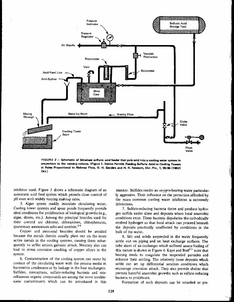
PressureIndicator
Air Supply
Manometer"
Vent=
Acid Feed line
Anti-Siphon
VariableRestriction
Rotameter
MixingThrough
Make Up Water ~ Gravity Flow
GlobeValve
FloatValve
FIGURE 2 - Schematic of blowcase sulfuric acid feeder that puts acid into a cooling water system in
proportion to the makeup volume. (Figure 1. Device Permits Feeding Sulfuric Acid to Cooling Towersat Rates Proportional to Makeup Flow, G. H. Sanders and H. R. Newsom, Mat. Pro.• 1, 95-96 (1962)Oct.)
inhibitor used. Figure 3 shows a schematic diagram of anautomatic acid feed system which permits close control ofpH even with widely varying makeup rates.
5. Algae spores readily inoculate circulating water.Cooling tower systems and spray ponds frequently provideideal conditions for proliferation of biological growths (e.g.,algae, slimes, etc.). Among the principal biocides used fortheir control are chlorine, cWoramines, cWorphenates,quaternary ammonium salts and acrolein.2 0
Copper and mercurial biocides should be avoidedbecause the metals therein usually plate out on the moreactive metals in the cooling systems, causing them subsequently to suffer serious galvanic attack. Mercury also canlead to stress corrosion cracking of copper alloys in thesystem.
6. Contamination of the cooling system can occur bycontact of the circulating water with the process media inbarometric condensers or by leakage in the heat exchangers.Sulfides, mercaptans, sulfate-reducing bacteria and miscellaneous organic compounds are among the more troublesome contaminants which can be introduced in this
129
manner. Sulfides render an oxygen-bearing water particularly aggressive. Their int1uence on the protection afforded bythe more common cooling water inhibitors is extremelydeleterious.
7. Sulfate-reducing bacteria thrive and produce hydrogen sulfide under slime and deposits where local anaerobicconditions exist. These bacteria depolarize the cathodicallyevolved hydrogen so that local attack can proceed beneaththe deposits practically unaffected by conditions in thebulk of the water.
8. Silt and solids suspended in the water frequentlysettle out on piping and on heat exchange surfaces. Thetube sheet of an exchanger which suffered severe fouling ofthis nature is shown in Figure 4. Kaye and Bird2 1 note thatheating tends to coagulate the suspended particles andenhance their settling. The relatively loose deposits whichsettle out set up differential aeration conditions whichencourage corrosion attack. They also provide shelter thatpermits harmful anaerobic growths such as sulfate-reducingbacteria to proliferate.
Formation of such deposits can be retarded or pre-

FIGURE 5 - Pitted and eroded steel heat exchanger headfrom the Piketon, Ohio Atomic Energy Commission gaseousdiffusion plant.20
FIGURE 4 - Heat exchanger fouled by biological growths.(Figure 1. Acrolein-A Biocide for Slime Control in CoolingWater Systems. J. M. Donohue, A. J. Piluso and J. R.Schieber, Mat_ Pro., 5, No. 7, 2-24 (1966) July.)
the sewage plant operation. Sufficient aerobic digestionreduces the phosphate level considerably. Lime treatmentwith subsequent alum flocculation and fIltration occasionally is used to reduce the high phosphate content of sewageeffluents before their introduction to the cooling system.26
130
I
FIGURE 3 - Two-element pH control which minimizes timelag and permits accurate control within a very narrow range.(Figure 7. Automatically Controlled Chemical Feeding Systems. G. W. Schweitzer, Mat. Pro., 1, 23-28(1962) Jan.)
CCI\IlENSING WlTER CIRCUIT
ACID
~ ~~t·~R ~_ r--' -•----1 11' 5 ~'R I MANUAL
IJPPLY CONTROLI STATION
I " ,
Q- I ! RELAY
, I
___ I I'
pHRECORDINGTRANSMITTER IL FLOW
RECORDING
• TRANSMITTER'__.-, _. __.J
vented by anti-coagulants. On the other hand, removal ofthose which already have settled out generally requires adifferent, in fact almost opposite, type of treatment.
Silt and loose deposits may be removed by treatmentswhich break up the deposits into loose agglomerates whichcan readily be flushed from lines and heat exchangers. Theprocess appears to involve a lowering of the affinity of thesolid surface for water, with a resultant tendency for theindividual particles to clump together in loose agglomerates.
Such processes are particularly effective for relatively looseiron deposits. Materials such as polyacrylamides, polyacrylic acid and long chain polyphosphates (Kurrol Salts)have been used for this purpose. Applications of treatmentsof this type have been discussed by Sherry,2 2 Schweitzer23and Zierden.24
Silt removal treatments are used intermittently, usuallyonce or twice a day and are among the few treatmentssufficiently economical to be used rather extensively inonce-through cooling systems. Control of deposits impedesthe establishment of differential aeration cells and in this
manner helps to alleviate the corrosion.9. Sewage plant effluent has been used as makeup for a
number of cooling systems for many years. Its use for thispurpose was described by Wolman in 1948.25
The chief problem raised by sewage effluent makeupstems from its high phosphate content which leads toproblems with calcium phosphate deposition. Thephosphate level may run to 40 mgfl or more, depending on

Nitrogen (chiefly ammonia) levels of sewage planteffluents also are relatively high. This, together with thehigh phosphate, accentuates the necessity for good controlof biological growths.
10. Industrial waste water which frequently is relatively free from contamination, serves as makeup for numerouscooling systems. On the other hand, the recirculatingsystem occasionally is used to facilitate removal of specificcontaminants. For example, Mohler27 describes the use ofcooling tower systems to promote biological oxidation ofphenols. The adaptability of such a mode of waste disposalmust be restricted to effluents whose contaminants do not
interfere with the operation of the system or with corrosioncontrol.
Materials Used in Cooling Systems
Carbon Steel
Carbon steel is widely used in heat exchangers and indistribution piping of recirculating cooling systems andnormally is the primary target of inhibitor treatment. The
success of such treatment determines how extensively steelmay be used to replace the more expensive copper alloytubes in the heat exchangers. Effect of corrosion on a caststeel exchanger head is shown in Figure 5.
Copper Alloys
The use of copper tubes in heat exchangers is limitedby their relatively high sensitivity to impingement attack.Velocities of 4 to 5 ft/sec are about the maxima that can be
tolerated with clean, fresh, recirculating water without
undue risk of such attack. An entrained second phase (i.e.,suspended solids, air bubbles, etc.) will markedly lower thevelocity that can be tolerated.
Copper alloy tubes are considerably more resistant toimpingement than the pure copper and consequently arewidely used in heat exchanger service. Admiralty metal isperhaps the most commonly used of these alloys in heatexchangers. It provides better resistance to impingementthan copper or red brass, tolerating velocities up to 7 to 8ft/sec in clean, fresh, cooling water.
Admiralty metal (Copper Development Association No.442), in common with other brasses with more than 15%
zinc is susceptible to dezincification. Stagnant areas and
areas under deposits are especially susceptible to this typeof corrosion. Dezincification generally is considered to
involve corrosion of the alloy as a whole, with subsequentredeposition of the copper in a rather spongy form.Sensitivity to dezincification can be reduced greatly byadding very small amounts of arsenic, (CDA 443) antimony(CDA 444) or phosphorus (CDA 445) to the alloy.28Almost all of the Admiralty metal used in heat exchangersis now inhibited in this manner. There have been indica
tions that the usual minimum levels of these alloyingadditions (Le., 0.02%) may not suffice for optimumprotection. Somewhat higher levels (e.g., 0.04%) appearpreferable.
Inhibited Muntz metal occasionally is used in heatexchangers, but its general resistance to attack is not as
131
good as that of Admiralty. Protection against dezincification conferred by arsenic is less pronounced with Muntz
metal than is the case with the single-phase, alpha brassAdmiralty.
Arsenical aluminum brass (CDA 687) is highly resistantto impingement attack at velocities up to 11 ft/sec in fresh
water and 8 ft/sec in clean sea water. It is highly susceptibleto localized attack under deposits or under low flowconditions.
Cupro-nickel is more commonly used in heat exchangers cooled by sea water than in fresh water service.
Small amounts of iron in these alloys render them highlyresistant to impingement attack. Cupro-nickels are susceptible to localized attack under loose deposits both in freshand in sea water service. Denickelification of 70-30 cupronickel (CDA 715) which resulted from inadequate flow andaccumulation of deposits in fresh water service is illustrated
by Figure 6. The latter shows a magnified cross-section of a
pit in a tube from a shell-side cooler in a recirculatingcooling system. In this instance life of the cupro-nickeltubes was even less than that of the Admiralty which it hadreplaced. Cupro-nickels frequently perform better under
high velocities in which suspended solids have less tendencyto settle out than they do at low rates of flow.2 9
Stainless Steels
Austenitic stainless steels are highly resistant to impingement attack and are used for both fresh and sea water
cooling. They are very susceptible to differential aeration
attack under deposits, hence strict precautions against theaccumulation of either deposits or biological growths ontheir surfaces are imperative.
FIGURE 6 - Magnified cross-section of a pit in a 7~30cupronickel tube of a shell-side cooler from a fresh waterrecirculating system. The lighter material in the upperportion of the photograph is metallic copper, while thecontinuous bright area at the bottom is the sound cupronickel; the gray areas reflect the mounting medium. (Photo:Calgon Corp., Pittsburg. Pa.)

Aluminum
Aluminum heat exchanger tubes are made very attrac·tive by certain process side considerations. The chief reasonfor this is their resistance to sulfides, mercaptans andcarbon dioxide. Aluminum, in common with other metalswhich rely on a tight oxide film for protection, is sensitiveto differential aeration attack in crevices, under loosedeposits and biological accretions.
Dissolved copper is particularly aggressive to aluminumon which it deposits and sets up galvanic cells which lead tosevere pitting. Copper-aluminum local cells are difficult tocontrol. A very low rate of attack on cuprous areas of arecirculating system suffices to produce deleterious levels ofdissolved copper (e.g., 0.05 mg/l). Galvanic protectionafforded aluminum alloys clad with an anodic layer of purealuminum makes the clad material somewhat more resistantto such attack.
Many smaller cooling towers used in air conditioningservice, etc. are constructed of aluminum. Both aluminumand redwood fill are used in these towers.
Wood
Larger cooling towers are commonly constructed ofwood. For many years redwood was more or less thestandard for such service because of its inherent resistance
to rot and decay. Biocidally treated Douglar fir and othermore plentiful species now are being used more often.Copper, an active constituent of many biocides, can leachfrom the wood into the cooling water if the biocides arenot suitably formulated, so precautions should be taken toinsure that such leaching will not occur.
Wood is subject to both chemical and biological attack.Excessive chlorination (e.g., continuous residuals of I mg/lor more) and high alkalinity can lead to delignificationwhich usually is restricted to the surface layers. Attack bywood-destroying microorganisms is concentrated in theinterior and is more insidious and generally more destructive than chemical attack. Treatment with wood preservatives (i.e., biocides) appears an effective means to combatsuch attack.3o Further discussion of the problem isprovided by the Cooling Tower Institute,31 Yoel32 andKaye and Bird.33 Deterioration of wood in the vicinity ofuncoated iron fasteners in a cooling tower is shown inFigure 7. Regutti and Power found that the wooddestroying organisms could be killed by steam treatment ofthe infected cooling towers.34 They also found thatbiocides could be steam distilled into the wood to delaypossible reinfection. Applications of the treatment arediscussed by McConomy.35 Table 2 gives some of theparameters of steam sterilization.
Pretreatment of Cooling Water
Treatment of cooling water serves essentially as aconvenient means of applying the inhibitor to metalsurfaces. Because grease, scale, corrosion products andmiscellaneous debris impede ready access of the inhibitor tometal surfaces, they retard the establishment of protection.
New units or systems should be cleaned and protectionestablished before appreciable corrosion has occurred and
132
FIGURE 7 - Showing rotted zones in a wooden coolingtower adjacent to iron fastenings.
TABLE 2 - Sterilization Steam and FungicideRequirements in 15 Cells( 1)
CellLb. SteamDimensions
Per CellLb. FungicideTower
HWLIX 10(0)Hr.Per Cell
A
253232 1006150B
263063 905275C
402930 -5190D
253036 246300E
263036 819(2 )
F
293040 81990G
303556 10012.5600H
122123 -4 70I
322463 432.5(2)
J
322463 622200K
263576 3305.5300L
383560 45014450M
383560 36012450N
203084 -82000
364784 804750
~1)Table 2, Reference 3S.2)Not used.
care should be taken that tubes of new exchangers are notblocked with construction debris. All too often new units
are hydraulically tested and allowed to stand for considerable periods before the system is put in operation, withresult that the system starts with prerusted units.
Operating units should be freed of scale and oldcorrosion products and protection established beforeappreciable further attack occur.
Rapid establishment of protection may be attained bytemporary application of relatively high levels of theinhibitor to be used in the system or, alternatively, speciallyformulated treatments may be used. When special formulations are used, the pretreatment must be compatible withtreatment to follow in subsequent operation of the system.
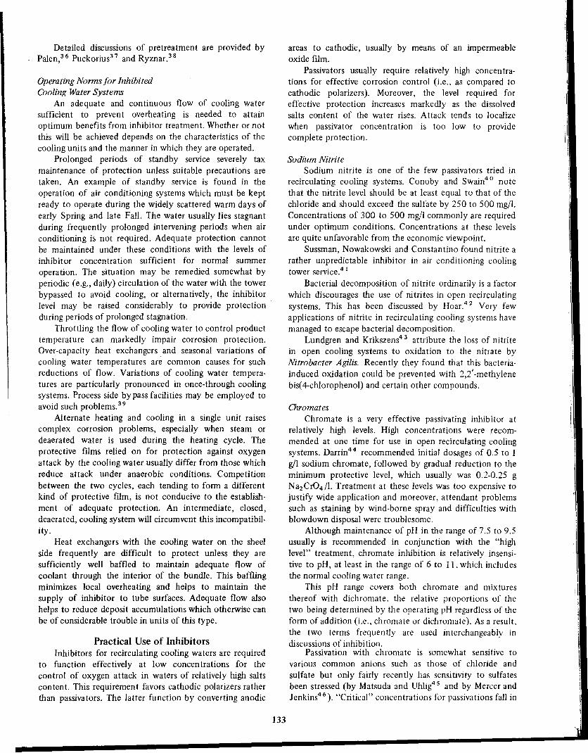
Detailed discussions of pretreatment are provided byPalen,36 Puckorius37 and Ryznar.38
Operating Norms for InhibitedCooling Water Systems
An adequate and continuous flow of cooling watersufficient to prevent overheating is needed to attainoptimum benefits from inhibitor treatment. Whether or notthis will be achieved depends on the characteristics of thecooling units and the manner in which they are operated.
Prolonged periods of standby service severely taxmaintenance of protection unless suitable precautions aretaken. An example of standby service is found in theoperation of air conditioning systems which must be keptready to operate during the widely scattered warm days ofearly Spring and late Fall. The water usually lies stagnantduring frequently prolonged intervening periods when airconditioning is not required. Adequate protection cannotbe maintained under these conditions with the levels ofinhibitor concentration sufficient for normal summer
operation. The situation may be remedied somewhat byperiodic (e.g., daily) circulation of the water with the towerbypassed to avoid cooling, or alternatively, the inhibitorlevel may be raised considerably to provide protectionduring periods of prolonged stagnation.
Throttling the flow of cooling water to control producttemperature can markedly impair corrosion protection.Over-capacity heat exchangers and seasonal variations ofcooling water temperatures are common causes for suchreductions of flow. Variations of cooling water temperatures are particularly pronounced in once-through coolingsystems. Process side by pass facilities may be employed toavoid such problems.39
Alternate heating and cooling in a single unit raisescomplex corrosion problems, especially when steam ordeaerated water is used during the heating cycle. Theprotective films relied on for protection against oxygenattack by the cooling water usually differ from those whichreduce attack under anaerobic conditions. Competitionbetween the two cycles, each tending to form a differentkind of protective film, is not conducive to the establishment of adequate protection. An intermediate, closed,deaerated, cooling system will circumvent this incompatibility.
Heat exchangers with the cooling water on the sheelside frequently are difficult to protect unless they aresufficiently well baffled to maintain adequate flow ofcoolant through the interior of the bundle. This bafflingminimizes local overheating and helps to maintain thesupply of inhibitor to tube surfaces. Adequate flow alsohelps to reduce deposit accumulations which otherwise canbe of considerable trouble in units of this type.
Practical Use of InhibitorsInhibitors for recirculating cooling waters are required
to function effectively at low concentrations for thecontrol of oxygen attack in waters of relatively high saltscontent. This requirement favors cathodic polarizers ratherthan passivators. The latter function by converting anodic
133
areas to cathodic, usually by means of an impermeableoxide film.
Passivators usually require relatively high concentrations for effective corrosion control (i.e., as compared tocathodic polarizers). Moreover, the level required foreffective protection increases markedly as the dissolvedsalts content of the water rises. Attack tends to localize
when passivator concentration is too low to providecomplete protection.
Sodium Nitrite
Sodium nitrite is one of tlle few passivators tried inrecirculating cooling systems. Conoby and Swain40 notethat the nitrite level should be at least equal to that of thechloride and should exceed the suifate by 250 to 500 mg/I.Concentrations of 300 to 500 mg/l commonly are requiredunder optimum conditions. Concentrations at these levelsare quite unfavorable from the economic viewpoint.
Sussman, Nowakowski and Constantino found nitrite a
rather unpredictable inhibitor in air conditioning coolingtower service.4 1
Bacterial decomposition of nitrite ordinarily is a factorwhich discourages the use of nitrites in open recirculatingsystems. This has been discussed by Hoar.42 Very fewapplications of nitrite in recirculating cooling systems havemanaged to escape bacterial decomposition.
Lundgren and Krikszens43 attribute the loss of nitritein open cooling systems to oxidation to the nitrate byNitrobacter Agilis. Recently they found that this bacteriainduced oxidation could be prevented with 2,2'-methylenebis( 4-chlorophenol) and certain other compounds.
Chromates
Chromate is a very effective passivating inhibitor atrelatively high levels. High concentrations were recommended at one time for use in open recirculating coolingsystems. Darrin44 recommended initial dosages of 0.5 to 1g/l sodium chromate, followed by gradual reduction to theminimum protective level, which usually was 0.2-0.25 gNa2Cr04/1. Treatment at these levels was too expensive tojustify wide application and moreover, attendant problemssuch as staining by wind-borne spray and difficulties withblowdown disposal were troublesome.
Although maintenance of pH in the range of 7.5 to 9.5usually is recommended in conjunction with the "highlevel" treatment, chromate inhibition is relatively insensitive to pH, at least in the range of 6 to 11. which includesthe normal cooling water range.
This pH range covers both chromate and mixtures
thereof with dichromate, the relative proportions of thetwo being determined by the operating pH regardless of theform of addition (i.e .. chromate or dichromate). As a result,the two terms frequently are used interchangeably indiscussions of inhibition.
Passivation with chromate is somewhat sensitive tovarious common anions such as those of chloride and
sulfate but only fairly recently has sensitivity to sulfatesbeen stressed (by Matsuda and Uhlig4S and by Mercer andJenkins4 6). "Critical" concentrations for passivations fall in
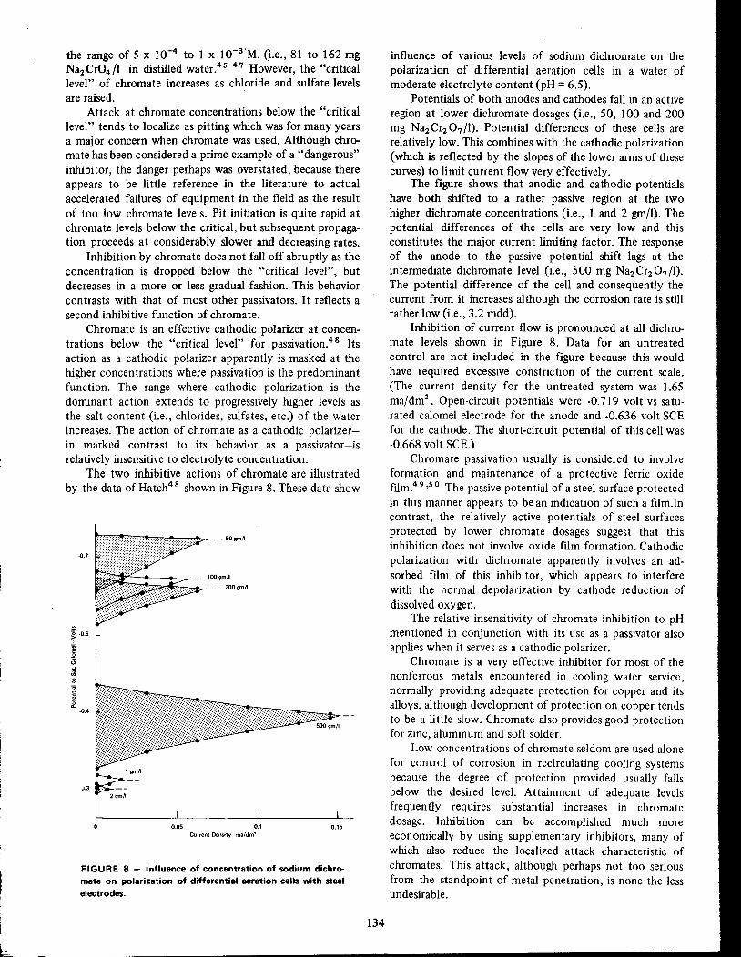
FIGURE 8 - Influence of concentration of sodium dichromate on polarization of differential aeration cells with steelelectrodes.
the range of 5 x 10⁻⁴ to 1 x 1O-3'M. (i.e., 81 to 162 mgNa2Cr04/1 in distilled water.45-47 However, the "criticallevel" of chromate increases as chloride and suIfate levelsare raised.
Attack at chromate concentrations below the "critical
level" tends to localize as pitting which was for many yearsa major concern when chromate was used. Although chromate has been considered a prime example of a "dangerous"inhibitor, the danger perhaps was overstated, because thereappears to be little reference in the literature to actualaccelerated failures of equipment in the field as the resultof too low chromate levels. Pit initiation is quite rapid atchromate levels below the critical, but subsequent propagation proceeds at considerably slower and decreasing rates.
Inhibition by chromate does not fall off abru ptly as theconcentration is dropped below the "critical level", butdecreases in a more or less gradual fashion. This behaviorcontrasts with that of most other passivators. It reflects asecond inhibitive function of chromate.
Chromate is an effective cathodic polarizer at concentrations below the "critical level" for passivation.48 Itsaction as a cathodic polarizer apparently is masked at thehigher concentrations where passivation is the predominantfunction. The range where cathodic polarization is thedominant action extends to progressively higher levels asthe salt content (i.e., chlorides, sulfates, etc.) of the waterincreases. The action of chromate as a cathodic polarizerin marked contrast to its behavior as a passivator-isrelatively insensitive to electrolyte concentration.
The two inhibitive actions of chromate are illustrated
by the data of Hatch4 8 shown in Figure 8. These data show
influence of various levels of sodium dichromate on the
polarization of differential aeration cells in a water ofmoderate electrolyte content (pH = 6.5).
Potentials of both anodes and cathodes fall in an active
region at lower dichromate dosages (i.e., 50, 100 and 200mg Na2 Cr2 07 /1). Potential differences of these cells arerelatively low. This combines with the cathodic polarization(which is reflected by the slopes of the lower arms of thesecurves) to limit current flow very effectively.
The figure shows that anodic and cathodic potentialshave both shifted to a rather passive region at the twohigher dichromate concentrations (i.e., 1 and 2 gm/I). Thepotential differences of the cells are very low and thisconstitutes the major current limiting factor. The responseof the anode to the passive potential shift lags at theintermediate dichromate level (i.e., 500 mg Na2 Cr2 07 /1).The potential difference of the cell and consequently thecurrent from it increases although the corrosion rate is stillrather low (i.e., 3.2 mdd).
Inhibition of current flow is pronounced at all dichromate levels shown in Figure 8. Data for an untreatedcontrol are not included in the figure because this wouldhave required excessive constriction of the current scale.(The current density for the untreated system was 1.65ma/dm2. Open-circuit potentials were -0.719 volt vs saturated calomel electrode for the anode and -0.636 volt SCE
for the cathode. The short-circuit potential of this cell was-0.668 volt SCE.)
Chromate passivation usually is considered to involveformation and maintenance of a protective ferric oxidefJJm.49,50 The passive potential of a steel surface protectedin this manner appears to be an indication of such a film.Incontrast, the relatively active potentials of steel surfacesprotected by lower chromate dosages suggest that thisinhibition does not involve oxide film formation. Cathodic
polarization with dichromate apparently involves an adsorbed film of this inhibitor, which appears to interferewith the normal depolarization by cathode reduction ofdissolved oxygen.
The relative insensitivity of chromate inhibition to pHmentioned in conjunction with its use as a passivator alsoapplies when it serves as a cathodic polarizer.
Chromate is a very effective inhibitor for most of thenonferrous metals encountered in cooling water service,normally providing adequate protection for copper and itsalloys, although development of protection on copper tendsto be a little slow. Chromate also provides good protectionfor zinc, aluminum and soft solder.
Low concentrations of chromate seldom are used alone
for control of corrosion in recirculating cooling systemsbecause the degree of protection provided usually fallsbelow the desired level. Attainment of adequate levelsfrequently requires substantial increases in chromate
dosage. Inhibition can be accomplished much moreeconomically by using supplementary inhibitors, many ofwhich also reduce the localized attack characteristic of
chromates. This attack, although perhaps not too seriousfrom the standpoint of metal penetration, is none the lessundesirable.
134
0.150.05 0,1Current Density~ma/dml
2gm~
J.3
-0.4
-0.6
-0.7
b..

The toxicity of chromate and its staining tendency areamong its disadvantages. Blowdown disposal raisesproblems wherever chromate is used in recirculating coolingwater service.
Silicates
The inhibitive properties of the silicates have beenknown since the early twenties, yet their adoption for usein recirculating cooling systems has been quite slow. Evennow they are largely restricted to smaller systems, such asthose used in air conditioning.
It was recognized from the start that establishment ofprotection with the soluble silicates is rather slow, usuallyrequiring 3 or 4 weeks to develop fully. Levels of 25 to 40mg Si02/1 commonly are used in cooling water. Initially,pH was not considered a particularly critical factor, as longas it was not below 6, but in practice, levels of 8 to 9.5appear more common.
In 1952, Lehrman and Shuldener5 I found the protective film produced by silicates to consist of a hydrated gelof silica and metal oxide.
Wood, Beecher and Laurence52 discussed more recent
experience with the use of silicates in industrial coolingwater systems. They recommended operation at a level of35 ± 5 mg/l of crystalloidal silica (i.e., silica reactive tomolybdate) after an initial period of several weeks atdouble this rate. They noted an improvement in theinhibition when the pH was dropped from 8.6 to 7.
Wood, Beecher and Laurence also found high magnesium levels to be detrimental to silicate inhibition leadingto severe pitting52 and set the magnesium limit tentativelyat 250 mg/I. The interference appeared more complex thanwould be expected from simple precipitation of magnesiumsilicate.
It is interesting to note that as of 1966, Sussman53found that answers were still needed for such fundamental
questions as the amount of silica required for optimum mmformation, the role of the silica content of the watersupply, the influence of the Na2 O:Si02 ratio of the silicateused and even the optimum pH for protective mmformation.
Silicate is a quite effective inhibitor for nonferrousmetals. In fact, early suggestions for its use as an inhibitorwere concerned with control of lead pickup54 and ofattack on galvanizing.5 5 It is effective for copper and itsalloys and has been particularly useful for control of thedezincification of yellow brass.
Polyphosphates
Polyphosphates have been used rather widely forcorrosion control during the past 30 years. Their inhibitionefficacy has been augmented during the latter portion ofthis period by admixture with other inhibitors, yet polyphosphate is still used alone in many systems where thecorrosion problems are not too severe. It is among the moreeconomically attractive inhibitive treatments.
The polyphosphates used for corrosion control arelinear polymers of the following general formula:
f ON,]
IN,O- o-p- -ON,
~ x where, x=2 or more
135
The sodium salts of the two lower members
pyrophosphate for x = 2 and triphosphate for x = 3-arecrystalline, while the higher members are amorphousglasses. The glassy members consist of mixtures of differentchain lengths and generally are classified according to theaverage chain length. The 67% P2 Os glass commonlyemployed for corrosion control has an average chain length(Le., x) of 14 to 16.
The inhibitive action of polyphosphates is not radicallyaltered by the chain length of the polymer. Pyrophosphateis more susceptible to precipitation and with the exceptionof the alkaline range, appears somewhat less stable than thehigher polymers. Susceptibility of the calcium salts toprecipitation also increases at very long chain lengths.Overall, the optimum range for corrosion control appears tobe from x = 3 to about 20. The calcium salts or complexesare the active inhibitive species of the polyphosphates.
Levels of 10 to 15 mg/l of polyphosphates normally aremaintained for corrosion control in circulating water,while roughly double these levels are advisable during thefirst several days of treatment. The pH should be held inthe range of 5 to 7 if iron and steel are the sole materialsinvolved but the presence of copper or its alloys narrowsthis pH range to 6.7 to 7. Adequate control of biologicalgrowths is essential for satisfactory inhibition.
Failure to maintain a suitable pH is probably the mostfrequent cause for poor results with polyphosphates. Itleads to several difficulties. In the first place, the degree ofprotection afforded by polyphosphates falls off as the pHrises above 7. The deterioration becomes quite pronouncedaround pH 7.4 and above. Secondly, pH levels above 7promote localized attack and tuberculation as the form of
attack which may occur in the presence of poly phosphatesremains characteristic of the pH. Furthermore, calciumorthophosphate deposition becomes an increasingly severeproblem as pH rises above 7.
Orthophosphate is introduced by reversion (i.e.,hydrolysis) of the poly phosphate. Normally it does notraise too serious a problem at pH levels of 7 or below, but itcan be troublesome even at these levels if the orthophosphate concentration becomes too high (i.e., > 8-12 mgP04/l).
Biological growths adhering to metal surfaces aredeleterious to polyphosphate inhibition, setting up differential aeration cells and impeding access of inhibitor to thesurface. In addition, they give rise to local anaerobicconditions which permit proliferation of specifically harmful organisms, such as suIfate-reducing bacteria, adjacent tothe m~tal surface. Hydrolytic breakdown of polyphosphates is accelerated greatly by a number of differentmicroorganisms.
Polyphosphates or their reversion product, orthophosphate, serve as a nutrient for biological growths and willencourage such growths unless remedial measures are taken.Fortunately, the polyphosphatesdo not affect the susceptibility of biological growths to cWorine or other biocides.
Polyphosphates are very effective for control of thenormal galvanic attack where junctions of dissimilar metalcomponents are involved.56 In contrast, they are quite
'I

ineffective for control of galvanic couples which developduring operation of the system as the result of depositionof dissolved cathodic metals on the more active metal
components of the system.S 7 Commonly occurring couplesof this type are those formed by copper picked up by thewater from copper or copper alloy portions of the systemand deposited on iron or steel components.
The reason for the difference in the response of thesetwo types of couples to the inhibitive action of thepolyphosphate is not obvious, but possibly stems fromthe relative accessibility of the respective cathodes to theinhibitor. The troublesome copper deposits appear to beloosely adherent and porous. The undersides of thesedeposits, which are relatively inaccessible to the polyphosphate, appear to be the active cathodes of cells formed inthis manner and consequently they are not amenable topolyphosphate control.
Very low rates of attack on cuprous metals-too low tocause appreciable damage to them-suffice to produce thesedeleterious amounts of copper.
Adjustment of the pH of circulating water to 6.7 orabove generally limits the copper pickup so that it will notcause trouble (Le., to 0.1 mg/l or less). This quitedrastically restricts the pH range for polyphosphate inhibition.
Occasionally, excessive copper pickup persists to pHlevels above 7. In such cases, the use of auxiliary copperinhibitors such as 2-mercaptobenzothiazoles 7,58 or1,2,3-benzotriazoles 9 is indicated. These inhibitors are
extremely effective even at pH levels considerably belowthe limit for polyphosphate inhibition of steel. Their usewill be considered later in greater detail.
Deposition of the protective film is a rather gradualprocess at the polyphosphate levels normally used forcooling water treatment. While an adequate supply ofpolyphosphate to the metal surface is particularly important during establishment of this film, lower rates suffice formaintenance once the film has developed.
The character of the flow, as well as its rate, is animportant factor determining the supply of inhibitor to themetal surface. Turbulent flow obviously brings more of thewater, hence inhibitor, into contact with the metal surface
than does laminar flow.60 Polyphosphate diffuses tooslowly to provide an adequate rate of supply, at least atnormal feed rates.
Because polyphosphates are adsorbed on numerousmetal oxides, including corrosion products, the supply ofinhibitor available for protective mm formation is reducedby the presence of such material. Aluminum carry over froma clarifier will precipitate and remove a considerableamount of phosphate from circulating water. This can beprevented by the addition of fluoride61 or fluorosilicate.The ratios required for such stabilization suggest thatfluoaluminate (AIF 6-3) is involved.
Loose deposits, oily mms and miscellaneous debrishinder ready access of polyphosphate to the metal surface.As a result, they retard the establishment of protection andpromote differential aeration activity and localized attack.Palen36 has demonstrated the importance of removing oily
136
mms (e.g., residues from manufacture, fabrication, etc.)from new tubes on subsequent protection with polyphosphates.
Although polyphosphate inhibition is relatively insensitive to concentration of salts in electrolytes, high concen·tration levels usually increase the corrosivity of the waterand for this reason require slightly higher polyphosphatedosages.
The protective mm, which consists largely of thecalcium salt of the polyphosphate, is deposited on thecathodic areas by a process of electrodeposition. 62 It is laiddown by the corrosion process and is self-limiting.Appreciable amounts of these phosphates (i.e., roughly 4mg P2 Os /dm2) are incorporated in a well-developed,protective mm.62 The mm generally includes minoramounts of iron and orthophosphate, both of whichenhance its protective nature.63 The beneficial action ofiron was brought out by Lamb and Eliassen.6 4
The polyphosphate film markedly increases cathodicpolarization, as has been shown by Mansa and Szybalski6sand by Hatch.s6 This is the principal inhibitive action ofpolyphosphate.
Raistrick66 has suggested that the inhibitive action ofpolyphosphates involves stabilization of a very thin film ofcalcite, oriented in a manner such that the calcium atoms inthe plane adjacent to and parallel to the metal surface areequidistant from each other. Polyphosphate because of itsgood geometric fit is considered to adsorb on this face.6 7
The distance between calcium atoms on this face (Le., 4.96A) is very similar to that between the phosphorous atoms
of the -O-P-O-P-O-P- chain (Le., 4.99 A). However, it isdifficult to reconcile such a mechanism with the deteriora
tion of polyphosphate inhibition in the alkaline ran~ (i.e.,pH > 7), in which calcium carbonate is more stable.Moreover, the quantity of phosphate in the protective filmis roughly 50-fold greater than is required to inactivate asimilar area of calcium carbonate.62
Roughly 70 to 80% of the phosphate in films strippedfrom steel after good protection had been developed (i.e., 2to 5 days) was in a molecularly dehydrated form.62 Thiscontrasts with the suggestion that the protective mm iscalcium orthophosphate.6 8 The latter was based on polarization measurements after very brief immersion (i.e., 5min)--too brief to permit appreciable mm deposition.6 2
Most of the disadvantageous features of poly phosphateinhibition already have been mentioned, but perhaps themost significant one is the gradual rate at which protectiondevelops. Acceleration of protection appears to be theprimary contribution of many inhibitors used in conjunction with polyphosphates. Pretreatment (e.g., removal ofgrease and deposits, a relatively high inhibitor dosage, etc.)also is helpful for mitigation of this problem.
Among the advantageous features of polyphosphateinhibition are its moderate cost, high electrolyte toleranceand lack of toxicity.
Calcium CarbonateCalcium carbonate is seldom relied on for corrosion
control in recirculating cooling systems because the protec-

tive calcium carbonate scale impedes heat transfer. Furthermore, it is difficult to deposit a mm of uniform thicknessthroughout a system which involves a variety of temperature levels, such as is found in a cooling system. Powell,Bacon and Lil169,70 found that a calcium carbonate
saturation index which is not altered by temperaturechanges can be attained by proper control of pH andalkalinity. Such controls have not proved particularlyattractive and practical applications are scarce.
The use of calcium carbonate for corrosion control is
considered in greater detail in the chapter on potable waterinhibitors.
Zinc Salts
Zinc salts markedly increase cathodic polarization 71and thus serve as corrosion inhibitors. Their action generally is attributed to precipitation of zinc hydroxide on thecathodic areas as a result of the locally elevated pH.72
Although protection is established rapidly by zinc salts, itis not very durable. Accordingly, zinc is not used alone asan inhibitor for recirculating cooling water. Zinc salts havelong been considered as safe, but inefficient inhibitors.
However, zinc is very effective in combination withmany other inhibitors, (e.g., polyphosphates, phosphonates,low concentrations of chromates, etc.) particularly withother cathodic polarizers. The combinations generally reflect the rapid establishment of protection characteristic ofthe zinc, but rely on the other member for durability.
Multi-Component InhibitorsMixtures of inhibitors frequently provide better inhibi
tion than similar concentrations of either of the individual
components (i.e., the mixtures are synergistic). This wasrecognized by Speller 73 in the mid-thirties, who reportedfinding "compound mms", such as formed by phosphatechromate mixtures, to be more effective than those ofeither alone.
Palmer 74 later confirmed that the chromate-orthophosphate mixture gave better inhibition than either of theindividual constituents and also found the mixture toreduce localized attack. This action he attributed to a
change from a gelantinous to a crystalline corrosionproduct, because the latter presents a less formidablebarrier to the access of oxygen to a metal surface.
Although it was not until the early fifties thatapplication of multi-component inhibitors became widespread, the number of mixed inhibitors has since increasedsubstantially. They are now used widely, particularly wherecorrosion problems are severe.
Chromate-PolyphosphateThe first of the modern generation of multi-component
inhibitors were the chromate-polyphosphate mixtures
described by Kahler and George,75 ,76 who found them tobe more effective than those with orthophosphate. However, orthophosphate could be substituted for a substantialportion (e.g., 50%) of the polyphosphate without muchimpairment of inhibition. These mixtures reduce thenumber of active areas and provide better overall inhibitionthan either of their individual components.
137
Kahler and George recommended levels of 50-75 mg/lof the inhibitive mixture and noted that the requiredinhibitor dosages varied with the severity of the particularproblem. The preferred ratio of sodium polyphosphate tosodium chromate is 2: 1. However, this does not appearparticularly critical, at least in the range of about 4: 1 to1:4. The pH range for optimum protection of iron and steelis 5.5 to 7.8 but the upper limit frequently must be loweredto avoid calcium phosphate deposition.
The flexibility of the treatment described by Hess77 isexemplified by an application to the circulating coolingsystem(l) of an oil refinery. A level equivalent to 30 to 35mg/l of a 1:4 sodium polyphosphate-sodium chromatemixture sufficed for protection under the severely corrosiveconditions characteristic of such service.
Chromate-polyphosphate inhibitors also are effectivefor protection of nonferrous metals in a cooling system.This includes copper and its alloys, aluminum, galvanizedsteel and soft solder.
The protection of copper and its alloys permitsoperation at pH levels low enough (e.g., 6 to 6.5) to avoidpossible trouble from calcium phosphate deposition even atrelatively high orthophosphate levels. Copper pickup and itssubsequent re deposition on iron and steel does not create aproblem at these low pH levels with this inhibitive mixture.
The chromate-polyphosphate treatment was named"Dianodic" by Kahler and George,76 who considered bothconstituents to be anodic inhibitors, but actually, at theconcentration levels involved, both constituents functionprimarily as cathodic polarizers.48,6 2 This appears to bethe chief inhibitive function of the mixture; the relative
insensitivity of the inhibition concentration of salts iscompatible with such action (i.e., cathodic polarization).polarization).
There is considerable uncertainty as to why a mixtureof these two inhibitors is superior to either alone. Kahlerand George 76 suggested that the mixture cleans awaycorrosion products and provides ready access of chromateto the entire metal surface. The mixture reflects the rapidestablishment of protection characteristic of chromate. Thissuggests that the slower forming polyphosphate mm servedto reinforce the chromate.
Probably the chief advantage of the chromatepolyphosphate combination is its efficacy for controllingcorrosion of both ferrous and nonferrous components of acooling system under rather severely aggressive conditions.Furthermore, control of the treatment is not particularlydifficult or critical.
A disadvantage is that the chromate in the mixture issusceptible to reduction by contaminants. Moreover,because the polyphosphate component is a nutrient forbiological growths, this increases the necessity for controlof such growths.
The relatively high levels of each of the constituentsincreases blow down disposal problems because the
(1)The circulating water was very hard (roughly 1500 mg{l asCaC03), high in sulfate and contained roughly 1800 mg{l totaldissolved solids. The pH was 6.5 to 7.0.
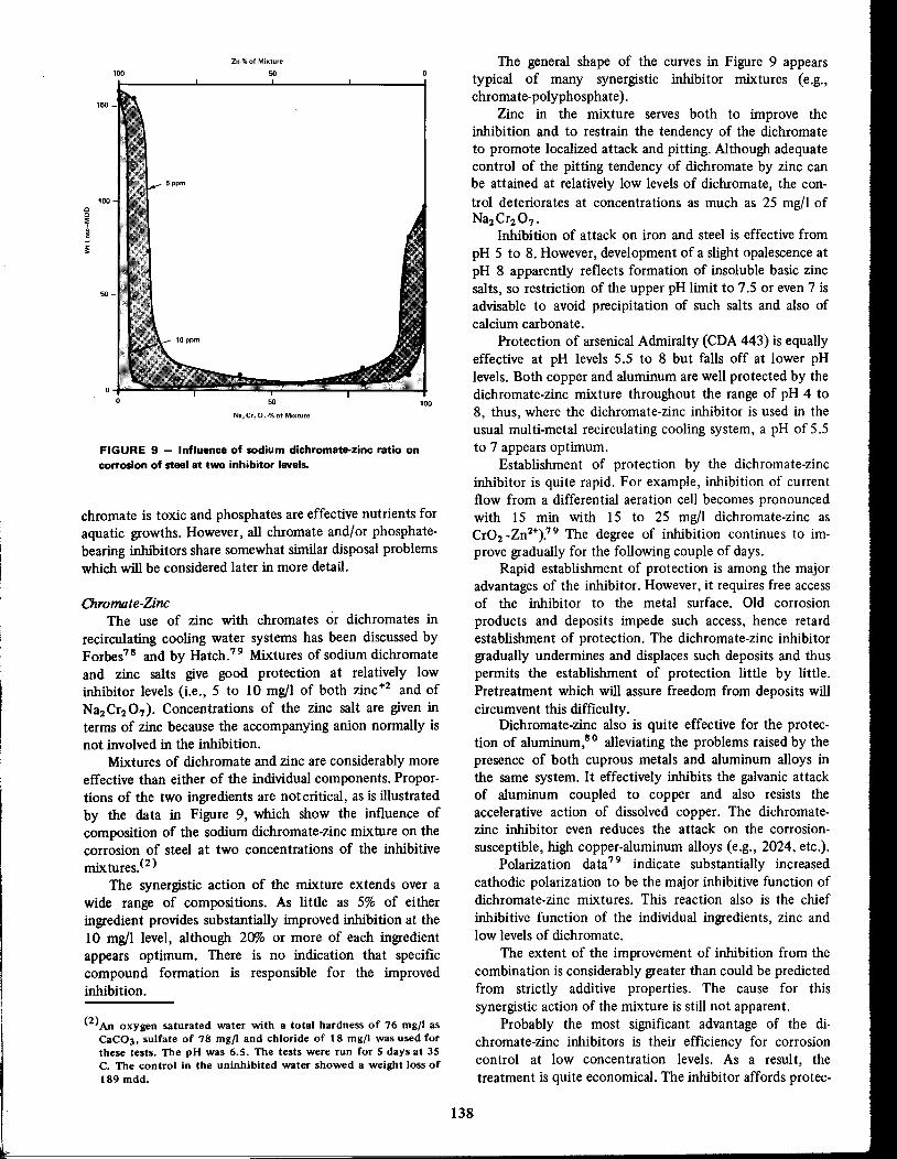
(2)An oxygen saturated water with a total hardness of 76 mgll asCaC03. sulfate of 78 mgll and chloride of 18 mgll was used forthese tests. The pH was 6.5. The tests were run for 5 days at 35C. The control in the uninhibited water showed a weight loss of189 mdd.
The general shape of the curves in Figure 9 appearstypical of many synergistic inhibitor mixtures (e.g.,chromate-polyphosphate ).
Zinc in the mixture serves both to improve theinhibition and to restrain the tendency of the dichromateto promote localized attack and pitting. Although adequatecontrol of the pitting tendency of dichromate by zinc canbe attained at relatively low levels of dichromate, the con
trol deteriorates at concentrations as much as 25 mg/l ofNa2Cr207'
Inhibition of attack on iron and steel is effective from
pH 5 to 8. However, development of a slight opalescence atpH 8 apparently reflects formation of insoluble basic zincsalts, so restriction of the upper pH limit to 7.5 or even 7 isadvisable to avoid precipitation of such salts and also ofcalcium carbonate.
Protection of arsenical Admiralty (CDA 443) is equallyeffective at pH levels 5.5 to 8 but falls off at lower pHlevels. Both copper and aluminum are well protected by thedichromate-zinc mixture throughout the range of pH 4 to8, thus, where the dichromate-zinc inhibitor is used in theusual multi-metal recirculating cooling system, a pH of 5.5to 7 appears optimum.
Establishment of protection by the dichromate-zincinhibitor is quite rapid. For example, inhibition of currentflow from a differential aeration cell becomes pronouncedwith 15 min with 15 to 25 mg/l dichromate-zinc asCr02 _Zn2+).' 9 The degree of inhibition continues to improve gradually for the following couple of days.
Rapid establishment of protection is among the majoradvantages of the inhibitor. However, it requires free accessof the inhibitor to the metal surface. Old corrosion
products and deposits impede such access, hence retardestablishment of protection. The dichromate-zinc inhibitorgradually undermines and displaces such deposits and thuspermits the establishment of protection little by little.Pretreatment which will assure freedom from deposits willcircumvent this difficulty.
Dichromate-zinc also is quite effective for the protection of aluminum,80 alleviating the problems raised by thepresence of both cuprous metals and aluminum alloys inthe same system. It effectively inhibits the galvanic attackof aluminum coupled to copper and also resists theaccelerative action of dissolved copper. The dichromatezinc inhibitor even reduces the attack on the corrosion
susceptible, high copper-aluminum alloys (e.g., 2024, etc.).Polarization data 79 indicate substantially increased
cathodic polarization to be the major inhibitive function ofdichromate-zinc mixtures. This reaction also is the chief
inhibitive function of the individual ingredients, zinc andlow levels of dichromate.
The extent of the improvement of inhibition from thecombination is considerably greater than could be predictedfrom strictly additive properties. The cause for thissynergistic action of the mixture is still not apparent.
Probably the most significant advantage of the dichromate-zinc inhibitors is their efficiency for corrosioncontrol at low concentration levels. As a result, thetreatment is quite economical. The inhibitor affords protec-
138
100
50
50
Zn-% of Mixture
100
FIGURE 9 - Influence of sodium dichromate-zinc ratio oncorrosion of steel at two inhibitor levels.
cc::;I]i
chromate is toxic and phosphates are effective nutrients for
aquatic growths. However, all chromate and/or phosphatebearing inhibitors share somewhat similar disposal problemswhich will be considered later in more detail.
Chromate-ZincThe use of zinc with chromates or dichromates in
recirculating cooling water systems has been discussed byForbes78 and by Hatch.79 Mixtures of sodium dichromateand zinc salts give good protection at relatively lowinhibitor levels (i.e., 5 to 10 mg/l of both zinc +2 and ofNa2 Cr2 07), Concentrations of the zinc salt are given interms of zinc because the accompanying anion normally isnot involved in the inhibition.
Mixtures of dichromate and zinc are considerably moreeffective than either of the individual components. Propor
tions of the two ingredients are not critical, as is illustratedby the data in Figure 9, which show the influence ofcomposition of the sodium dichromate-zinc mixture on thecorrosion of steel at two concentrations of the inhibitivemix tures. (2 )
The synergistic action of the mixture extends over awide range of compositions. As little as 5% of eitheringredient provides substantially improved inhibition at the10 mg/l level, although 20% or more of each ingredientappears optimum. There is no indication that specificcompound formation is responsible for the improvedinhibition.

tion to all metals commonly encountered in cooling waterservice. Control is relatively simple. The treatment containsno ingredients which can serve as nutrients for biologicalgrowths and this frequently simplifies the required biocidalmeasures.
Disadvantages include the retardation of the establishment of protection by old deposits. Although the dichromate-zinc mixture gradually undermines such deposits,it does not have the detergent properties of polyphosphatebearing inhibitors, nor does it have the threshold propertiesof these phosphates with respect to calcium carbonate andcalcium sulfate. When dichromate-zinc is used, thesedeposits must be avoided strictly by solubility considerations. It does, however, circumvent the calcium phosphatedeposit problem.
Chromote-Polyphosphate-ZincKahler, Tanzola and George81,8 2 have described the
improvement of inhibition brought about by the use of zincsalts along with the chromate-polyphosphate mixture.Addition of zinc permitted a substantial reduction of thechromate-polyphosphate dosage without sacrifice of inhibitive efficiency. For example, ID to 25 mg/l of a mixturewith a weight ratio of Zn +2:Nas P3 010 :Na2 Cr04 of2:2: I provided inhibition comparable to that obtained with60 mg/l Nas P3010 + 30 mg/l Na2 Cr04.
When used in conjunction with chromate-polyphosphate, zinc levels generally range from 0.8 to ID mg/I,while pH levels usually are kept below 7 to avoid zincphosphate deposition. Alternatively, the pH may be heldabove this level and a thin layer of zinc phosphatedeposited on the metal surface. Kahler and George82 notethat such a layer affords good protection and can becontrolled readily. The thickness of the zinc phosphatescale is controlled by adjustment of the relative proportionsof ortho- and poly- phosphates. The latter exert asolubilizing action of the coating.8 2
All three components of the chromate-polyphosphatezinc mixture are good cathodic polarizers at the concentration levels involved and any pair thereof provides synergistic enhancement of inhibition. Consequently, the efficacyof the combination of all three is perhaps not toosurprising. The polyphosphate contributes detergent anddispersive properties to the mixture as well as enhances itsinhibitive action.
Comeaux83 has suggested that the zinc serves toprecipitate a mm of zinc hydroxide and/or zinc orthophosphate on the cathodic areas, while the chromate precipitates an insoluble ferric-chromic hydroxide,3Fe(OHh Cr(OH)3 over the anodic sites. The two depositspresumably combine to stifle attack. The presence of anyprecipitated mm has not been demonstrated at pH levelsappreciably below 7, nor does such a mm seem to beessential in view of the inhibitive efficacy of the variousinhibitor pair mentioned above (e.g., chromate-zinc andchromate-polyphosphate) .
Chromate-polyphosphate-zinc has the advantage overchromate-polyphosphate in that it provides comparable Iinhibition at lower concentrations. Otherwise, the two
139
types of inhibitive mixtures share much the same advantages and disadvantages.
Polyphosphate-Zinc
The use of zinc salts in conjunction with polyphosphates considerably augments their inhibitive action.The zinc markedly increases the rate at which protection isestablisheds 7 ,84 and in so doing improves inhibition.
The general nature of polyphosphate inhibition is notaltered appreciably by the zinc nor are requirements forinhibition, such as the presence of calcium and the pHlimits changed. Characteristics of the inhibition, such as itstolerance to concentrations of salts and its relative applicability to various nonferrous metals, also remain essentiallyunchanged.
The increased rate of protective mm formationprovided by the zinc alleviates one of the more disadvantageous features of polyphosphate inhibition (Le., its slowrate of establishing protection). Zinc also acceleratesre-establishment of protection when breaks in the protective mm occur, so the overall result is general improvementof the inhibition. When the corrosion problem is notsufficiently severe to require the added zinc, its use permitsmaintenance of given levels of protection with lowerconcentrations of polyphosphate.
The inhibitive efficiency of the mixture increases
sharply with the initial increments of zinc. After roughly 10to 20% zinc has been incorporated in the mixture,subsequent increments provide little further benefit.Although the optimum level of zinc varies somewhat with
the polyphosphate concentration, it is not sufficientlycritical to warrant adjustment of the ratio for each specificpolyphosphate dosage.
The nature of the anion which accompanies the zinc isnot critical. It may be added as the sulfate, chloride,nitrate, polyphosphate, etc. Concentrations of 8.5% zinc
are about the maxima which can be incorporated in aphosphate glass without undue retardation of its solutionrate,8S
Both zinc and polyphosphate are effective cathodicpolarizers and mixtures of the two are even more active inthis respect.
Polyphosphate-zinc inhibition reflects the rapidestablishment of protection characteristic of zinc, as well as
the durability of the polyphosphate mm. Apparently, therapid initial protection afforded by the zinc restrains attack
until the more durable, but slower forming polyphosphatemm can build up. Thus, actions of the zinc and polyphosphate seem to be separate, but supplementary. There are noindications that zinc phosphate deposition is involved in theinhibition.
While zinc accelerates establishment of protection, itretards somewhat63 the incorporation of phosphate in themm. The resultant mms are thinner, but more protective.
Polyphosphate-zinc inhibition retains the same sensitivity to dissolved copper which characterizes applications of
polyphosphates alone. The narrow pH range (i.e., 6.7 to7.0) required in recirculating systems which containcuprous metals is not altered by the zinc.

NaO ONa\/
O=PI
CH2
NaO, INaO•......P- CH2 - N- CH2 _ p ONa" II-ONa
o 0
inhibitor. Compounds with iminobis (methylenephosphonate) groups behave similarly.
The structure of the sodium salt of NTMP is given inFigure 10.
Phosphonates are considerably more stable to hydrolysis than are polyphosphates. The phosphorous atoms arelinked directly to carbon atoms. These bonds are notsubject to hydrolysis. In contrast, oxygen-phosphorouslinkages in the polyphosphate chain (-O-P-O-P-O-P-) aresusceptible to hydrolytic cleavage.
Stability of the phosphonates eliminates one source ofinhibitor consumption (i.e., reversion), but the chief advantage is that it eliminates calcium phosphate deposition andits attendant problems.
Although its structure is quite different, NTMP sharesmany of the properties of the polyphosphates:
oNTMP-Inhibitor Percent
50----L-STEEL
pH 6.5 - 7
50Zn-Inhibitor Percent
FIGURE 10 - Showing structure of sodium salt of NTMP.
FIGURE 11 - Influence of NTMP-zinc ratio on the corrosionof steel at several inhibitor levels. (Figure 3, Reference 961
o
100150
Cl)Cl)o.-J
....:50:!:
Polyphospha te-SilicatePolyphosphates have been used with silicates in recir
culating cooling systems for two reasons:1. To inhibit calcium carbonate scale deposition and2. To provide better corrosion inhibition.
The former has been successful, but the latter remains of
questionable value. Maintenance of levels of 2 mg/l polyphosphate suffices for maximum stabilization of calciumcarbonate, while higher levels generally are used forcorrosion control.
Initial applications of polyphosphate-silicate treatmentfor corrosion control were in potable systems, particularlyin hot waters.8 6,87 Results were rather erratic.
Ulmer and Wood88 discussed the use of polyphosphate-silicate mixtures in cooling systems, suggesting thatthe preferred range of pH for inhibition by the mixture was6 to 6.5. The characteristic localization of attack and
pitting in the pH range of 7 to 9 persisted in spite of thepresence of the inhibitor mixture. Unfortunately, thesehigher pH levels probably have been the more common inapplications of the polyphosphate-silicate inhibitors.
There is little published information about preferredratios of polyphosphate to silicate for corrosion control.
Use of polyphosphate-silicate mixtures as corrosioninhibitors for recirculating cooling systems has not beenvery successful, so applications are sparse and largelyrestricted to smaller systems .
There is little indication that the combination behaves
other than in a strictly additive manner.
Polyphosphate-Fe"ocyanideRyznar and Peich89 found that the addition of
ferrocyanide to polyphosphate improved inhibition at hightemperatures (e.g., 82 C and above). Mixtures whichcontained around 20% ferrocyanide appeared quite effective for both steel and Admiralty metal.
Bregman and Newman90 found that low concentrations (e.g., 2 mg/I) of a number of metallic cations (i.e.,Co+2, Ce+3, Cr+3, Mn+2, Cd+2, Pb+2, Zn+2, Sn+2 and
Ni +2) enhanced inhibition by the polyphosphateferrocyanide mixture. Zinc is the cation usually selected forthis purpose. Excessive levels of metal cations negate theirbeneficial action, for example, the use of 10 mg/l zinc withthe mixture was without benefit. pH levels of 6 to 7 wereemployed in conjunction with the treatment.
The manner in which the ferrocyanide functions in themixture is not known. Alone, it is ineffective as aninhibitor.
Powe1l91 used the polyphosphate-ferrocyanide inhibitor in copper-tubed heat exchangers which operate attemperatures between 55 and 82 C (130 and 180 F). Heattributed to the ferricyanide the pitting which developed inthe copper tubes during this treatment.
Nitrilotris (methylenephosphonate) MixturesCombinations of nitrilotris (methylenephosphonate)
with zinc or dichromate provide good inhibition. Alone,this phosphonate (NTMP) is not a particularly promising
140
!

1. It forms complexes with calcium and numerousother polyvalent metal cations.
2. It is a good peptizing agent and dispersant.3. It stabilizes iron and manganese-bearing waters.924. It stabilizes supersaturation with respect to calcium
carbonate and calcium sulfate.93 ,94
5. It forms protective f1I.mson metal surfaces.9 5-9 7
Good inhibition is attained with 20 to 80% zinc in the
mixture, while 30 to 60% is optimum. This is illustrated bydata in Figure 11. Slightly lower inhibitor levels suffice foradequate protection when the zinc is held in the latter (i.e.,optimum) range. However, the higher proportions of zinc(i.e., > 30%) are not advisable at pH levels much above 7,because precipitation of basic zinc salts may be encountered.
The zinc is an even more essential component when
copper or its alloys are involved. While NTMP alone iscorrosive to cuprous metals, presumably a reflection of thestrength ofits copper complex, zinc not only prevents attackby the NTMP, but renders the mixture inhibitive. Thisaction of the zinc appears to involve formation of asufficiently strong complex with NTMP to overcome thetendency of the latter to attack and complex the copper.Zinc should constitute at least 20% of the mixture in order
to insure adequate protection of copper and its alloys.
NTMP-zinc mixtures are relatively insensitive to pH andare inhibitive to iron and steel at pH levels from 4 to'8.5,
although results tend to become erratic at higher pH levels.Copper and Admiralty are inhibited by the mixtures at pHlevels above 5. However, 6.5 or above is preferred in orderto reduce copper pickup to a level such that it will notinterfere with the protection of iron and steel. Thus, thepreferred range for multi-metal recirculating systems is pH6.5 to 8.5.
Alone, NTMP serves as a cathodic polarizer at the levelsgenerally involved in cooling water treatment (i.e., 100mg/I). At higher concentrations (e.g., 500 mg/l) it serves asa passivator for iron and steel.
Increased cathodic polarization is the principal inhibitive function of the NTMP-zinc mixture and in this respectit reflects the action of each of its components. There is anincipient development of passivation at the higher pH levels(e.g., 8.3) which is reflected by a shift of potential towardsa passive region.96
A major advantage of NTMP-zinc inhibition is itsapplicability in the mildly alkaline range. This avoids thenecessity for acid treatment, which can prove ratherexpensive with a makeup of high alkalinity. Moreover,inhibition can be maintained in this alkaline region withoutdeposit problems. The high hydrolytic stability of theNTMP effectively eliminates calcium phosphate deposits.The zinc is apparently held in solution as an NTMPcomplex. It should be noted that any attack which mayoccur in such systems probably will be in the form typicalof the pH (i.e., pitting and tuberculation in the alkalineregion).
NTMP has a deftnite cWorine demand. Consequently,where control of biological growths is required, non-
141
oxidizing biocides are indicated for use in conjunction withNTMP-zinc inhibition.
Ethanoldisphosphonate Mix turesEthanoldisphosphonate (EDP) is one of the more
recent inhibitive components for cooling water treatment.Its sodium salt has the structure shown in Figure 12. Alone,it is not especially effective, but in combination with otherinhibitors it provides very good protection. Hwa hasdescribed the use of EDP with dichromate,9 7,98 whileHatch99 suggested its use with zinc salts.
The EDP:Na2 Cr2 07 ratio required for satisfactoryinhibition does not appear very critical. Hwa98 discussesfteld applications with mixtures containing from 9 to 25%EDP while laboratory results at 67% were promising. Totalinhibitor levels used in these applications ranged from 8 to22 mg/l with pH in the range 6.8 to 7.2. Hwa found theEDP-dichromate mixture also to be effective for control of
attack on aluminum and cuprous metals.Zinc markedly increases the inhibitive action of EDP.
The corrosion rate of steel falls off quite rapidly as the zinccontent of the mixture is raised to about 23%, but furtherincrements are of little additional beneftt. The proximity ofthis "break" (23%) to a 1: 1 mole ratio of zinc:EDP (24%Zn by wt) suggests a deftnite compound of zinc and EDP tobe involved.
Zinc plays an additional role in the mixture bycounteracting the aggressive action of EDP on copper andits alloys and rendering mixtures with 23% or more zincinhibitive to these metals.
Zinc:EDP mixtures are inhibitive to iron and steel at
pH levels from 5 to 9.5. When copper or its alloys areinvolved, the lower pH limit should be raised to 6.5.Recommended concentrations for recirculating coolingwater service generally fall in the range of 10 to 25 mg/I forthe 30 zinc-70 EDP mixture.
Action of zinc in the mixture does not appear toinvolve precipitation of zinc hydroxide or insoluble zincsalt. The zinc is bound sufficiently tightly by the EDP thatit does not precipitate from concentrated solutions (e.g.,20% at high pH, e.g., 10.5). This suggests that the zinccomplex is the inhibitive species. Apparently, the zincsatisftes the complexing tendency of EDP sufficiently torender it nonaggressive to copper and its alloys.
There is a rather close resemblance between many ofthe properties of EDP and NTMP. Both are strong chelatingagents for calcium and numerous other multi-valent cationsand both effectively stabilize calcium carbonate and cal
cium sulfate by threshold treatment (i.e., 1 to 3 mg/I).Their corrosion inhibitive mixtures also share many of thesame advantages and disadvantages.
CH3
NaO_ INaO •......•.P - C _ p•......•.ONa11 I 1I-0Na
o OH 0
FIGURE 12 - Showing structure of sodium salt of EDP.I
!
:d

The most significant difference between the performance of EDP and NTMP is the greater resistance of theformer to oxidation. As a result; EDP has no chlorine
demand and does not require non oxidizing biocides. TheEDP-zinc inhibitor also is effective to somewhat higher pHvalues than is the NTMP-zinc.
Other Organic-Based Mixtures
In recent years, increasingly stringent restrictions ondisposal of chromate- and/or phosphate-bearing blowdownhave stimulated the search for new inhibitors. This search
has concentrated in the organic field, perhaps due to thefeeling that the inorganic realm already has been coveredrather thoroughly.
Most organic inhibitors used in cooling water servicerequite the presence of some inorganic constituent to assureadequate performance. In the past, chromates andphosphates were commonly employed for this purpose, forexample, the rather ill-defined phosphoglucosates andchromoglucosates used by Haering.1 00 In recent years,chromates and phosphates have lost favor as they gainednotoriety as environmental pollutants. Zinc salts are nowthe more favored inorganic inhibitive constituent.
Mixtures of sulfonated tannins with zinc salts areinhibitive to iron and steel. Robertson1 0' states that the
presence of sugar acids is required for good inhibition withthe sulfonated tannin-zinc mixture. A pH of 6 to 8 usually isspecified when this inhibitive mixture is used. 2-Mercaptobenzothiazole frequently is included in this mixture toinsure protection of copper and copper alloy componentsof the system.
The sulfonated tannin-zinc-sugar acid mixtures appearto have performed quite adequately in a number of systemswhere corrosive conditions were not very severe, but theydo not appear to be as satisfactory under severely corrosiveconditions.
Sulfonated tannins and sugar acids, in common withmany organic inhibitive components, are sensitive tochlorination. They have a high chlorine demand. Consequently they require the use of nonoxidizing biocides andmoreover, the generally high BOD of such inhibitiveconstituents raises blowdown disposal problems.
Copper InhibitorsMost cooling water inhibitors which have been dis
cussed exert some degree of control over corrosion ofcopper and its alloys, but frequently their operative pHranges are rather drastically limited to control reduction ofdissolved copper to the very low levels required to avoidinterference with the protection of steel (Le., 0.1 mg/lmax). However, there are alternatives.
Auxiliary inhibitors are available which are very effective for control of copper pickup as well as the corrosion ofcuprous metals. Because they usually are not adequatelyprotective to iron and steel or other noncuprous components of a cooling system, they are seldom used alone.They include the following compounds.
142
2-Mercap tobenz othiazole
2-Mercaptobenzothiazole (Le., MBT) is an extremelyeffective inhibitor for copper and its alloys. It has beenused extensively as a corrosion inhibitor in glycol antifreezes since the early thirties' 02 in concentrations in therange of 0.5 to 2 gm/I.
More recently very low concentrations of MBT (e.g., 2mg/l) were found to suffice for reduction of attack on
cuprous metals in recirculating cooling systems to extremely low levels-too low to be detectable in the usual
short term laboratory test. 57,58 MBT also can preventdeposition of dissolved copper carried into the system ontoiron, steel or aluminum.
A minimum of 2 mg/l MBT is required to establishprotection at pH levels below -7. Lower concentrations
have relatively little effect. Inhibition develops ratherabruptly between 1 and 2 mg/l and appears to be fullydeveloped at 2 mg/I.
Protection is effective at pH levels from 3 to la orabove, essentially eliminating the necessity to consider
cuprous metals as a pH limiting factor in recirculatingcooling water treatment.
MBT is deleterious to polyphosphate inhibition of ironand steel unless zinc is present.S 3 The reason for this is notknown.
MBT is frequently fed intermittently. A typical procedure calls for 2 mg/l to be maintained in circulating waterfor 1/2 to 1 hour every day. Twelve hours later, a dosage ofhalf this amount (Le., I mg/l) is maintained for a similarperiod to facilitate mm repair.
Although MBT is sparingly soluble, this poses noproblems as far as the circulating water is concerned, butdoes complicate its application. To avoid this problem itfrequently is fed as the sodium salt, which is commerciallyavailable as a 50% aqueous solution. Because MBT is a veryweak acid, solutions of the sodium salt are highly alkaline.
MBT dissolved in circulating water is oxidized bychlorine or chloramines, but protection persists for aconsiderable period after chlorination. Apparently the MBTin the protective mm is not affected, perhaps reflecting itschemisorption on the copper surface with an orientationsuch as to shield the oxidation-susceptible sulfhydrylgroups from chlorine. When chlorine disinfection is used ina system intermittently treated with MBT, chlorine shouldbe applied a sufficiently long time before the major MBTapplication to permit dissipation of the free and combinedchlorine residual.
While MBT forms a sparingly soluble copper salt orchelate, it does not appear to be so insoluble that aprecipitated film thereof would provide the very highdegree of protection attained. The inhibition appears toinvolve chemisorption of MBT or its copper chelate on thecuprous metal surface. Such chemisorption may be enhanced by surface chelation in a manner such as suggestedby Weisstuch, Carter and Nathan' 03 for various otherinhibitors.
The extremely effective inhibitive action of MBT is its
chief advantage. Its susceptibility to oxidizing agents,

.,
Analytical ProceduresAnalytical procedures for most inhibitor constituents
TABLE 3 - Analytical Controls for Monitoring levelsof Inhibitive Mixtures in Recirculating Cooling Water Systems
in the system is essential for good protection. For economicreasons it is desirable to hold this concentration at the
minimum level which will provide such protection. Thisrequires rather careful control. While protective mmsformed by inhibitors generally will withstand temporaryfluctuations of inhibitor levels, this cannot be relied on forprotection over other than transitory periods of time.
Inhibitor levels in a recirculating cooling system areaffected by a number of factors besides rate of application,makeup volume and degree of concentration in the system.Air-borne or process contamination can increase inhibitorconsumption quite sharply. Quality of makeup, particularlywith regard to suspended solids and reducing contaminantsalso influences inhibitor consumption. Many of thesecontaminants not only consume inhibitor, but increase thecorrosivity of the water. Thus, maintenance of an effectivelevel of inhibitor is particularly needed during periods ofsuch contamination. However, it should be stressed thatcontrol of inhibitor level is not an adequate remedy forcontinual or persistent contamination. The latter should beeliminated.
Frequent and in some cases, continuous analyses of thecirculating water are required in order to maintain aminimum effective inhibitor level. Where multi-componentinhibitors are used, primary control usually is based on theone component most prone to consumption. However,periodic analyses for the other components should beconducted to assure an effective balance of the inhibitivemixture in the circulating water.
The relative susceptibility of inhibitor components toconsumption occasionally differs from one application toanother. In such cases it often is advisable to monitor theother components as well. Primary and secondary controlsfor some of the more common inhibitive mixtures areincluded in Table 3.
ZincZinc
ZincZinc
Zinc
Ferrocyanide
Analytical ControlPrimary I Secondary
Chromate and/or
polyphosphatePolyphosphateChromate and/or
polyphosphate
PolyphosphatePolyphosphonateZinc
NTMp(1)-zincEDP(2)-zincEDP(2)-chromate
Inhibitive Mixture
Polyphosphate-zincPolyphosphate-ferrocyan ideLignin sulfonate-zinc
Chromate-zinc
Chromate-polyphosphate-zi nc
Chromate-poly phosphate
PhosphonatePhosphonatePhosphonate and/or
chromate
(1)Nitrolitris/meth ylenephosphonate.(2)Ethanoldiphosphonate.
particularly chlorine and chloramines, is a definite disadvantage.
Control of Inhibitor LevelsMaintenance of a sufficient concentration of inhibitor
1,2, 3-Benzo triazole
1,2,3-Benzotriazole is a very effective inhibitor forcopper.s 9,104-106 It also can deactivate dissolved copperwhich may enter the system and prevent its deposition onsteel, galvanizing,etc.
Inhibition commences with the initial increments ofbenzotriazole and becomes fully developed at a concentration of about I mg/1.There is no lag as is observed withMBT at the lower pH levelsand inhibition is effective at pH5.5 to 10 or above.
Benzotriazole is very resistant to oxidation, yet itsinhibitive action is destroyed in the presence of freechlorine. However, inhibition returns once the chlorineresidual has dissipated. It is postulated that the chlorineforms with benzotriazole a chloramine which lacks inhibitive power. In any event, the inhibitive action of benzotriazole is unaffected by chloramines.s 9
The exact manner in which benzotriazole functions hasnot been established. Cotton and Scholes106 suggest itinvolves chernisorption of benzotriazole or the coppercomplex thereof on the copper surface. Benzotriazoleforms a rather tight copper complex and here again,chernisorption may be enhanced by surface chelation. 103
Among the advantages of benzotriazole are its stabilityand pronounced resistance to oxidation. Moreover, it doesnot interfere with polyphosphate inhibition regardless ofwhether or not zinc is present.
Disadvantages include its high c~kroughly 4 to 5times that of MBT. In addition, benzotriazole is not quiteas effective an inhibitor for copper as is MBT.
Fe",ous Sui/ate
Ferrous sulfate is a rather specialized inhibitor which isused to alleviate impingement attack of copper alloy,tubes.Its chief application has been in sea water or !:>rackish,waterservice. It has the distinction of being almost the pnlyinhibitor to enjoy appreciable application in once-throughcooling systems.
Applications of ferrous sulfate to power plant condensers cooled by brackish water was described byBostwick.107 He found that daily treatment for 45 minwith ferrous sulfate at a rate of I mg Fe/l practicallyeliminated failures of aluminum brass tubes from impingement attack. The treatment has since been extended toother copper alloy tubes.
A tightly adherent mm of hydrous ferric oxide-apparently is responsible for the protective action of theferrous sulfate. The mm is sufficiently thick (i.e., approx. 3rnils) to impart a dark reddish color to the metal surface.The treatment appears to serve a function somewhatanalogous to that of the iron in alloys such as thecupronickels. In each case the production of a mm ofhydrous ferric oxide is relied on for protection.
143/~.

CHEIIICAL FEEDPUr.lP
Newer Inhibitor Treatmentsto Meet Pollution Controls
Donohue and Sarnol 16 recently described treatments
containing very low concentrations of chromate, e.g., 5
ppm. These "ultralow" chromate treatments arc used at pHvalues of 8.0 or even above. At a high pH, corrosivity of the
system is reduced and acid feed for pH control usually isnot required. In order to prevent scaling problems whichwould normally be encountered at high pH values, it isnecessary to augment chromate with scale-preventing materials such as phosphonates and/or various organic polymers
Editor's Note: The following sections have been added since the
death of Or. Hatch in order to update his section on blow down
disposal and related topics involved in more recent water treatingmethods for cooling water.
chromate should not be discharged into streams or otherwaterways. More recently, discharge of phosphate has beencriticized but for a different reason. Phosphates are aneffective nutrient for biological growths. In addition zinc istoxic to some fish at levels of 1 mg/I/08 although the limitfor drinking water is 5 mg/1.109
Chromate can be removed by reduction-for example,with ferrous sulfate, sulfurous acid and its salts, etc.
followed by separation of the resultant chromic hydroxide.Mracek110 has discussed the factors involved in its reduc
tion by sulfur dioxide.Chromate also can be removed by ion exchange as
described by Hessler and Oberhoferl 11 and by Kelly.1 12Chromate is selectively removed by the chloride form of astrong-base resin, preferably from a slightly acid solution(e.g., pH 4.5). The chromate is released for reuse and theresin regenerated by a caustic solution of sodium chloride.The caustic soda converts the dichromate to chromate and
the chloride exchanges for the latter.Eliassen and Tchobanoglousl 13 recently have reviewed
the procedures for removal of phosphates from wastewater. Polyphosphates readily revert to orthophosphate inthe conventional sewage plant. The phosphate can beremoved by adsorption on activated sludge floc, precipitated with lime, alum or iron salts or adsorbed on activatedalumina. The latter has been discussed by Yee.l 14 Precipitation with lime was discussed in conjunction with the useof sewage plant effluent for makeup.2 6
The extent to which phosphates are removed inconventional sewage plants varies from 20 to 90%, depending on the degree of aeration of the activated sludge andpH. Menar and Jenkinsl 15 note that aeration removescarbon dioxide and raises pH, thus favoring calciumphosphate precipitation.
Apparently, methods for phosphate removal are stillin such a preliminary state of development that optimumprocedures have yet to be established.
Zinc is readily adsorbed by calcium carbonate 108 andsilt, so its removal does not appear too difficult.
Little information is available at this time regardingeither the necessity or the means for removal of the newerinhibitors NTMP and EDP.
144
CNElII CALSOLUTlOtlTANK
HAKE-UPWATER
CONDENSER
CDNDEtlSERWATER PU~IP
FIGURE 13 - Schematicof proportional feed system usingawater meter-timer combination. Increments of inhibitorsolution are injected at a frequency proportional to themakeup volume. (Figure 6, SeeReferenceto Figure 3)
Blowdown DisposalRecent emphasis on environmental protection requires
a closer look at blowdown disposal practices than has beentaken in the past. Few corrosion inhibitors now in use arecompletely unobjectionable from the standpoint of environmental contamination. This definitely applies to thethree most common inhibitive ingredients, chromates,
polyphosphates and zinc.It has long been recognized that because of their
toxicity, effluents containing appreciable concentrations of
are available in the literature and additional proceduresoften can be obtained from suppliers of the mixtures.Colorimetric methods generally are preferred because theyare relatively quick and amenable to automation. However,atomic absorption, if available, frequently is preferred forzinc.
Procedures for the newer inhibitive ingredients, the
phosphonates AMP and EDP, are generally less familar andwarrant additional consideration. Phosphonates cannot beconverted to P04 by simple hydrolysis, such as suffices for
the polyphosphates, but require strong oxidation (e.g.,persulfate) to break the Cop bond and accomplish theconversion. The strong chelating action of these phos
phonates also requires their destruction prior to colorimetric determination of the zinc.
Inhibitor feed is not as critical as is acid addition for pHcontrol because the protective film can withstand tempo
rary fluctuations of inhibitor levels. As a result, rapidresponse of the inhibitor feed is not essential. This permitsuse of relatively simple feed systems, one of which is shown
diagramatically in Figure 13.
SHUT OFFVALVE

which act as scale dispersants. Phosphonates used includenitrilotris (methylenephosphonate) and I-hydroxyethylidene 1, I-diphosphonate, which have. been described byRalston.117
Carter et a/118 recommend that for consistently goodresults with these treatments, the systems be subjected to apretreatment at a substantially higher chromate level andthat the Langelier Index be maintained at + 1.0 to 2.5during the uItralow chromate treatment.
Treatments in which chromate is eliminated completelyare described in a recent work by Carter and Donohue.119These treatments employ a mixture of phosphate (properlybalanced between polyphosphate and orthophosphate),phosphonates such as described above and/or organicpolymeric dispersants. A typical program calls for 3-10 ppmtotal phosphate, 2-5 ppm orthophosphate and pH in therange of 7.0 to 9.0. A high positive Langelier Index of I to2.5 is required and this necessitates at least 25 ppm ofcalcium (as CaC03). However, lOO ppm or more arepreferred values. Weisstuch and Schell120 report that boththe low chromate treatments and those containing nochromate described above are also effective in stiflinggalvaniccorrosion caused by contacts of dissimilarmetals inindustrial cooling systems.
At the higher pH values of the low chromate ornon-chromate treatments, the biocidal effectiveness ofchlorine is reduced, so larger quantities of chlorine .arerequired or alternatively, non-oxidizing biocides such aschlorophenates, quaternary nitrogen compounds, etc., areemployed. Donohue and Sarno discuss the pollution aspectsof these materials and of the corrosion inhibitors andsuggest the use of biocides such as acrolein, tertiary butylhydrogen peroxide and bromo-nitrostyrene. These materialshave the advantage of being easily detoxified by addition ofstoichiometric quantities of sodium sulfite.
In his discussion, Hatch stresses the need for closemaintenance of inhibitor levels and other operating parameters. One of the most important of these is pH. In thenewer treatments which employ low chromates or nochromates, the establishment and maintenance of protective fIlms is even more sensitive to changes in pH andinhibitor concentration than are those formed with conventional high-chromate treatments. Schieber12 1 discussesfactors involved in obtaining effective protection anddescribes the principles of operation and advantages ofautomatic control devices used in industrial cooling watersystems.
The entire field of cooling water treatment is presentlyin a state of flux of increasingly stringent requirements onpollution control being promulgated by Federal, state andmunicipal authorities. A considerable amount of work isbeing carried out by water service companies, universities,governmental agencies, etc., to solve these pollutionproblems in an economical as well as efficient and safemanner. The technical literature adquately covers currentwork and the reader is referred to the publications of theNational Association of Corrosion Engineers, to thejournals of other technical societies and to governmentreports for the latest developments in this important field.
145
References1. C. H. Kline. Water Otemical Sales are High, but Profits Scarce,
Paper presented at meeting of European Otemical MarketingResearch Assoc., Sept. 2, 1971, Summary in Mat. Pro.Perf., 10,41-43 (1971).
2. NACE Recirculating Cooling Water Sub-committee. SomeEconomic Data on Otemical Treatment of Gulf Coast CoolingWaters, Co"osion, 11,61-62 (1965) Nov.
3. Staff Feature Industrial Water Corrosion Control and Costs.Mat. Pro., 5,8-13 (1966) July.
4. O. W. Siebert and W. C. Engman. Case History on Economicsof Otemical Treatment of a Recirculating Water CoolingTower, Mat. Pro., 3,20-25 (1964) Oct.
5. D. B. Jones. Can You Afford Your Cooling Water TreatmentProgram, Mat. Pro., 4,62-67 (1965) March.
6. C. P. Dillon. Economic Evaluation of Corrosion ControlMeasures, Mat. Pro., 4, 38-45 (1965) May.
7. M. Brooke. Dollars and Sense in Cooling Water Treatment,Mat.Pro., 4,53-55 (1966) July.
8. B. Berg, R. W. Lane and T. E. Larson. Water Use and RelatedCosts with Cooling Towers, Circular 86, Illinois State WaterSurvey, Urbana, Ill. (1963).
9. C. S. Cone. A Guide for Selection of Cooling Water CorrosionInhibitors, Mat. Pro. Perf., 9, 32-34 (1970) July.
10. NACE Unit Committee T-7A. Cooling Water TreatmentManual, NACE, Houston, Texas (1971).
11. Selected Papers on Cooling Tower Water Treatment. Circular91, Illinois State Water Survey, Urbana, Ill. (1966).
12. Standard Heat Exchanger for Cooling Water Tests. A Reportof NACE Technical Unit Committee T-5C on Corrosion byCooling Water, Mat. Pro., 4, 70-72 (1965) Aug.
13. A. S. Krisher. NACE Standard Heat Exchanger MonitorsCooling Tower Water Corrosion, Mat. Pro., 4,73-79 (1965)Aug.
14. H. F. McConomy. literature Survey of Corrosion in CoolingWater Systems1 1940-1953, Proc. Am. Petro. Inst. Ill, 35,32-79 (1955).
15. J. K. Rice. Treatment of Recirculating Cooling Water, CO"Qsion, 8,375-380 (1952) Nov.
16. G. B. Hatch and O. Rice. Surface Active Properties ofHexametaphosphate,Ind. Eng. Chem .. 31,51-57 (1939) Jan.
17. O. Rice and E. P, Partridge. Threshold Treatment: Eliminationof Calcium Carbonate Deposits from Industrial Waters, Ind.Eng. Chem., 31,58-63 (1939) Jan.
18. P. H. Ralston. Scale Control with Aminomethylenephosphonates, J. Petro. Tech., 1029-1036 (1969) Aug.
19. G. H. Sanders and H. R. Newsom. Device that Permits FeedingSulfuric Acid to Cooling Towers at Rates Proportional toMakeup Flow, Mat. Pro., 1,95-96 (1962) Oct.
20. J. M. Donohue, A. J. Piluso and J. R. Schieber. Acrolein-ABiocide for Slime Control in Cooling Water Systems, Mat.Pro., 5,22-24 (1966) July.
21. S. Kaye and P. G. Bird. Stop Silt Settling in Exchangers,Hydro. Proc. Petro. Ref., 44, 149-152 (1965) Aug.
22. A. Sherry and E. R. Gill. Current Trends in Corrosion Controlat West Thurrock Power Station, Chem. & Ind., 102-106(1964) Jan.
23. G. W. Schweitzer. Silt Control Treatment in Cooling WaterSystems, Proc. Int. Water Conf. (W. Penna. Engrs. Soc.) 26,74-76 (1965).
24. T. W. Zierden. Methods and Compositions for RemovingAlluvium and Other Deposits in Water Systems, U.S.Pat.3,503,879 (March 31, 1970).
25. A. Wolman. Industrial Water Supply from Processes SewageTreatment Plant Effluent at Baltimore, Maryland, SewageWorks J., 20,15-21 (1948) Jan.
26. S. L. Terry. Use of Sewage Plant Effluent as Cooling TowerMakeup, Selected Papers on Cooling Water Treatment, Circular 91, Illinois State Water Survey Urbana, Ill. (1966).
27. E. F. Mohler. Extended Experience in Biological Treatment

and Reuse of Refmery Waste Water in Cooling Towers, Int.Water Conf Proc. (W. Penna. Engrs. Soc.) 26, 21-37 (1965).
28. G. D. Bengough and R. May. Seventh Report to the CorrosionResearch Committee,./. Inst. Metals (Brit.), 32, 81 (1924).
29. D. B. Bird and K. L. Moore. Brackish Cooling Water vsRefinery Heat Exchangers, Mat. Pro., 1,71-77 (1962) Oct.
30. D. R. Baker. Controlling Deterioration of Cooling TowerLumber, Presented at 7th Annual Conf., Petroleum Div. Am.Soc. Mech. Engrs. (1952).
31. Report of Study of Wood Maintenance for Water CoolingTowers. Cooling Tower Institute, Houston, Texas, June 1959,Resume: Mat. Pro., 1,32-39 (1962) Oct.
32. W. Yoel. Determination and Prevention of Fungal Deterioration of Cooling Towers, Mat. Pro., 2,64-69 (1963) April.
33. S. Kaye and P. G. Bird. Measuring the Progress of Wood Rot inCooling Towers, Mat. Pro., 3,46-50 (1964) Oct.
34. C. W. Regutti and T. H. Power. Cooling Tower Preservation bySteam Sterilization and Chemical Distillation-A ProgressReport, Inter. Water Conf Proc. (W. Penna. Engrs. Soc.) 22,27-34 (1961).
35. T. A. McConomy. Cooling Tower Steam Sterilization: FourYears Progress, Mat. Pro., 5,51-53 (1966) Sept.
36. T. Palen. Reduce Cooling System Corrosion, Petro. Ref, 38,239-242 (1959) May.
37. P. R. Puckorius. Pretreatment-The Key to Effective Protection of Cooling Water Systems, Proc. Am. Water Conf (W.Penna. Engrs. Soc.) 21, 23-33 (1960).
38. P. R. Puckorius and W. J. Ryznar. Cooling Water InhibitorPerformance, Corrosion, 16, 473t-478t (1960) Oct.
39. W. S. Janssen. Corrosion Control in a Refinery Salt WaterCooling System, Mat. Pro., 1,42-53 (1962) Oct.
40. J. F. Conoby and T. M. Swain. Nitrite as a CorrosionInhibitor. Controlling Depletion of Sodium Nitrite, Mat. Pro.,6,55-58 (1967) April.
41. S. Sussman, O. Nowakowski and J. J. Constantino. Experiences With Sodium Nitrite, Unpredictable Corrosion Inhibitor,Ind. Eng. Chem., 51,581-583 (1959).
42. T. P. Hoar. Nitrite Inhibition of Corrosion: Some PracticalCases, Corrosion, 14, 103t-104t (1958) Feb.
43. O. G. Lundgren and A. Krikszens. U.S.Pat. 3,087,777 (April30, 1963).
44. M. Darrin. Corrosion Inhibition with Chromate.3- Gas
Processing Plants and Refineries, Oil & Gas./., 85-88 (1949)Feb.
45. S. Matsuda and H. H. Uhlig. Effect of pH, Sulfates, andChlorides on Behavior of Sodium Chromate and Nitrite asPassivators for Steel, J. Electrochem. Soc., 111, 156-161(1964) Feb.
46. A. D. Mercer and I. R. Jenkins. Comparative Study of FactorsInfluencing the Action of Corrosion Inhibitors for Mild Steelin Neutral Solution ll. Potassium Chromate, Brit. Corrosion J.,3,130-135 (1968) May.
47. W. D. Robertson. Molybdate and Tungstate as CorrosionInhibitors and the Mechanism of Inhibition, J. Electrochem.Soc., 98,94 (1951).
48. G. B. Hatch. Influence of Inhibitors on Differential Aeration
Attack of Steel. ll-Dichromate and Orthophosphate, Paperpresented at 1964 NACE National Conference.
49. U. R. Evans. Inhibitors-Safe and Dangerous, Trans. Electrochem. Soc., 69, 213-231 (1936).
50. M. Cohen and A. F. Beck. Passivity of Iron in ChromateSolutions I-Structure and Composition of the Film, Z.Elektrochem., 62, 696 (1958).J. E. O. Mayne and M. J. J. Pryor. The Mechanism ofInhibition of Corrosion of Iron by Chromic Acid andPotassium Chromate,./. Chem. Soc., 1831-1835 (1949).U. R. Evans. The Corrosion and Oxidation of Metals, Edw.Arnold Ltd. (London) p. 151-157 (1960).
51. L. Lehrman and H. L. Shuldener. Action of Sodium Silicate
146
as a Corrosion Inhibitor in Water Piping, Ind. Eng. Chem.,44,1765-1769 (1952) Aug.
52. J. W. Wood, J. S. Beecher and P. S. Laurence. SomeExperiences with Sodium Silicate as a Corrosion Inhibitor inIndustrial Cooling Waters, Corrosion, 13, 719t-724t (1957)Nov.
53. S. Sussman. Silicates in Water Treatment, Ind. Water Eng.(1966) March.
54. J. C. Thresh. Analyst, 47,459-468,500-505 (1922).SS. F. N. Speller. J. Franklin Inst., 193,519-520 (1922).56. G. B. Hatch. Inhibition of Galvanic Attack of Steel with
Phosphate Glasses, Ind. Eng. Chem., 44, 1780-1786 (1952)Aug.
57. G. B. Hatch. Control of Couples Developed in Water Systems,Corrosion, 11,461 t-468t (1955) Nov.
58. G. B. Hatch. Corrosion Inhibiting Composition and Method ofUsing Same, U.S.Pat. 2,742,369 (August 17, 1956).
59. G. B. Hatch. Method of Inhibiting Corrosion of Copper andCuprous Alloys in Contact with Water, U.S.Pat. 2,941,953(June 21, 1960).
60. G. B. Hatch and O. Rice. Corrosion Control with Threshold
Treatment,lnd. Eng. Chem., 37,752-759 (1945) Aug.61. H. L. Kahler, C. A. Bishof and W. A. Tanzola. Corrosion
Inhibition in Water Systems, U.S.Pat. 2,848,299 (August 19,1958).
62. G. B. Hatch. Protective Film Formation with PhosphateGlasses, Ind. Eng. Chem., 44, 1775-1786 (1952) Aug.
63. G. B. Hatch. Poly phosphate Inhibitors in Potable Water, Mat.Pro., 8,31-35 (1969) Nov.
64. J. C. Lamb, III and R. Eliassen. Mechanism of CorrosionInhibition by Sodium Metaphosphate Glass, JA WWA, 46,445-460 (1954) May.
65. J. L. Mansa and W. Szybalski. Corrosion Due to Tuberculationin Water Systems, Acta Chem. Scand., 4, 1275-1292 (1950);Corrosion, 8,381-388 (1952) Nov.
66. B. Raistrick. Condensed Phosphates and Corrosion Control,Chem. & Ind., 408-414 (1952).
67. B. Raistrick. The Influence of Foreign Ions on Crystal Growthfrom Solution. I-The Stabilization of the Supersaturation ofCalcium Carbonate Solutions by Anions Possessing o-P-o-P-oChains, Disc. Faraday Soc., No. 5, 234-237 (1949).
68. Z. Szklarska-Smialowska and J. Mankowski. Mechanism of the
Action of Polyphosphates as Inhibitors of the Corrosion ofSteel by Water, Centre Beige D'Etude et de Doc. des Eaux,No. 288,474-482 (1967) Nov.
69. S. T. Powell, H. E. Bacon and J. R. Lill. Corrosion Preventionby Controlled Calcium Carbonate Scale, Ind. Eng. Chem., 37,842-846 (1945) Sept.
70. S. T. Powell, H. E. Bacon and E. L. Knowdler. CorrosionPrevention by Controlled Calcium Carbonate Scale, Ind. Eng.Chem., 40,453-457 (1948) March.
71. G. B. Hatch. Influence of Inhibitors on the Differential
Aeration Attack of Steel, Corrosion, 21, 179-187 (1965),June;Methods of Inhibiting the Pitting of Iron and Steel. U.S.Pat.3,022,133 (February 20, 1962).
72. R. S. Thornhill. Zinc, Manganese and Chromic Salts asCorrosion Inhibitors, Ind. Eng. Chem., 37, 706-708 (1945)Aug.
73. F. N. Speller. Discussion, Proc. ASTM, 36, (Part 2), 695-696(1936).
74. W. G. Palmer. Corrosion Inhibitors for Steel, J. Iron & SteelInst. (Brit.), 421-431 (1949) Dec.; Corrosion, 7, 10-19 (1951)Jan.
75. H. L. Kahler. Phosphate-Chromate Protection in WaterSystems, U.S.Pat. 2,711,391 (June 21, 1955).
76. H. L. Kahler and C. George. A New Method for the Protectionof Metals Against Pitting, Tuberculation and General Corrosion, Corrosion, 6, 331-340 (1950) Jan.
77. W. A. Hess. Refinery Corrosion Rates Below 5 mpy Achieved

by Chromate Water Treatment, Corrosion, 16, 18-21 (1960)July.
78. M. C. Forbes. Approaching Problems of Cooling WaterCorrosion,Petro. Ref, 36,164-165,216(1957) April.
79. G. B. Hatch. Low Level Dichromate-Zinc Inhibition in
Recirculating Cooling Water Systems, Mat. Pro., 4, 52-56(1965) July.
80. G. B. Hatch. Controlling Aluminum Attack in RecirculatingCooling Systems, Mat. Pro., 5,46-52 (1966) July.
81. H. L. Kahler and W. A. Tanzola. Inhibiting Corrosion inIndustrial Water Systems, U.S.Pat. 2,900,222 (August 18,1959).
82. H. L. Kahler and C. George. Decreasing Cooling WaterCorrosion,Petro. Ref, 34,144-148 (1955) July.
83. R. V. Comeaux. Basic Cooling Water Guide, Hydro. Proc., 46,129-132 (1967) Dec.
84. G. B. Hatch and P. H. Ralston. Oxygen Corrosion Control inFlood Waters, Mat. Pro., 3, 35-41 (1964) Aug.
85. G. B. Hatch. Phosphate Glass Composition. U.S.Pat.3,284,368 (November 8, 1966).
86. R. T. Halon, A. J. Steffen, G. A. Rohlich and L. H. Kessler.Scale and Corrosion Control in Potable Water Supplies atArmy Posts,lnd. Eng. Chem., 37,724-735 (1945) Aug.
87 F. N. Speller. Hot and Cold Water Systems, Corrosion Handbook (Uhlig) John Wiley & Sons, New York, p. 496-506(1948).
88. R. C. Ulmer and J. W. Wood. Prevention of Corrosion in
Cooling Water, Corrosion, 8,402-406 (1952) Dec.89. J. W. Ryznar and M. A. Peich. Corrosion Inhibiting Composi
tions and Method. U.S.Pat. 2,515,529 (July 18, 1959).90. J. I. Bregman and T. R. Newman. Developments in Cooling
Tower System Treatments. Part I-Polyvalent lon-Polyphos-. phate Inhibitors, Corrosion, 15, 97t-l00t (1959) Feb.
91. J. L. Powell. Corrosion of Copper in Open Recirculating Water. , Systems,lnd. Eng. Chem., 51, 75A-76A (1959) March.92. R. R. Irani. Sequestration of Metal Ions. U.S.Pat. 3,234,124
(February 8, 1966).93. P. H. Ralston. Method of Inhibiting Precipitation and Scale
Formation, U.S.Pat. 3,336,221 (August 15, 1967).94. P. H. Ralston. Scale Control with Aminomethylenephospho
nates,J. Pet. Tech., 1029-36 (1969) Aug.95. G. B. Hatch and P. H. Ralston. Method of Inhibiting Corrosion
with Aminomethylenephosphonic Acid Compositions,U.S.Pat. 3,483,133 (December 9,1969).
96. G. B. Hatch and P. H. Ralston. AminomethylenephosphonateZinc Mixtures Control Oxygen Corrosion, Mat. Pro. Perf, 11,39-42 (1972) Jan.
97. G. W. Schweitzer. Aminomethylenephosphonates ControlScale and Corrosion in Cooling Water Systems, Proc. Int.Water Conf (W. Penna. Engrs. Soc.) 30, 131-138 (1969).C. M. Hwa. Organic Phosphorous Acid Compound-ChromateCorrosion Protection in Aqueous Systems. U.S.Pat. 3,431,217(March 4, 1969).
98. C. M. Hwa. Use of Phosphonates for Treating Cooling WaterSystems, Proc. Int. Water Conf (W. Penna. Engrs. Soc.) 30,138-141 (1969).
99. G. B. Hatch. Corrosion Inhibiting with Combinations of ZincSalts and Derivatives of Methanolphosphonic Acid, U.S.Pat.3,532,639 (October 6, 1970).
147
100. D. W. Haering. Film Inhibitors in Industrial Aqueous Systems,Ind. Eng. Chem., 30, 1356-61 (1938) Dec.
101. R. S. Robertson and W. J. Ryznar. Cooling Water Treatmentand Compositions Useful Therein. U.S.Pat. 3,256,203 (June14,1966).
102. W. S. Calcott. U.S.Pat. 1,797,401 (March 24, 1931).103. A. Weisstuch, D. A. Carter and C. C. Nathan. Chelation
Compounds as Cooling Water Corrosion Inhibitors, Mat. Pro.Perf, 10,11-15 (1971).
104. J. B. Cotton. Control of Surface Reactions of Copper byMeans of Organic Compounds, Proc. 2nd Int. CongressMetallic Corrosion, New York 1963, p 590, NACE (1966).
105. I. Dugdale and J. B. Cotton. Corrosion Sci., 3,69 (1963).106. J. B. Cotton and I. R. Scholes. Benzotriazole and Related
Compounds as Corrosion Inhibitors for Copper, Brit. CO"os.J., 2, 1-5 (1967) Jan.
107. T. W. Bostwick.· Reducing Corrosion of Power Plant Condenser Tubing with Ferrous Sulfate, Co"osion, 17, 12-19(1961) Aug.
108. J. Finn. Saving Fish from Metal Poisons, Eng. News Record,125,9(1940).
109. Public Health Service Drinking Water Standards'-1962. PublicHealth Service Pub!. No. 956, U.S. Gov. Printing Office,Washington, D.C.
1l0. W. A. Mracek. Control and Automation of Chromate Was~eReduction Plants, Proc. I;u. Water Conf (W. Penna. EngIs.Soc.) 30, 91-9 (1969).
Ill. J. c. Hesler and A. W. Oberhofer. Recovery and Reuse ofChromates in Cooling Tower Discharge, Mat. Pro., 3, 8-22(1964) Dec.
Il2. B. J. Kelly. Cooling Tower Chromates-Recovery or Disposal,Mat. Pro., 8,23-5 (1969) March.
113. R. Eliassen and G. Tchobanoglous. Removal of Nitrogen andPhosphorous from Waste Water, Envir. Sci. Tech., 3,536-541(1969) June.
Il4. W. C. Yee. Selective Removal of Mixed Phosphates from WaterStreams by Activated Alumina, JA WWA, 58, 239-247 (1966)Feb.
115. A. B. Menar and D. Jenkins. Fate of Phosphorous in WasteTreatment Processes: Enhanced Removal of Phosphate byActivated Sludge/Envir. Sei. Tech., 4, 1115-1121 (1970) Dec.
116. J. M. Donohue and C. V. Sarno. Pollution AbatementPressures Influence Cooling Water Conditioning, Mat. Pro. &Pert, 10,19-21 (1971) December.
117. P. H. Rlilston. Inhibiting Water Formed Deposits with Threshold Compositions, Mat. Pro. & Pert, 11,39-44 (1972) June.
118. D. A. Carter, A. Weisstuch and W. L. Harpe!. TechnicalAspects of Modern Cooling Water Treatment. 1972 NorthCentral-Northeast NACE Meeting, Chicago, Ill., October16-18, 1972.
119. D. A. Carter and J. M. Donohue. New Protective Measures forCooling Systems, Mat. Pro. & Pert, 11, 35-38 (1972) June.
120. A, Weisstuch and C. E. Schell. Effectiveness of Cooling WaterTreatments as Galvanic Corrosion Inhibitors, Mat. Pro. &Pert, 11,23-26 (1972) November.
121. J. R. Schieber. Control of Cooling Water Treatments: AStatistical Study. Ninth Annual Liberty Bell Corrosion Course,Philadelphia, Pa., Sept. 13-15, 1971. Also available as Technical Paper, 218A, Betz Laboratories, Inc., Trevose, Pa. 19047.
,I

BILLY D. OAKES*
Inhibitors in Desalination Systems
17.835.313.021.3
95.417.546.9
0.30.3
5.35.10.2
12.937.2
43.210.28.5
18.53.8
29.615.9
1.3
3.262.9
247.2
247.2
241.6146.3
38.754.4
2.2
247.2
686
686
Plants
By Process
By Size, 103 gpd
Total
Total
By Geographic Area
Africa 437
Note: Includes plants producing 25,000 gpd or more.
(I)Office of Saline Waler, U.S. Depl. Inlerior.
TABLE 1 - Desalting Plants in Operation orUnder Construction - January 1, 1969( I)
Distillation 646
Multi-Stage Flash 229Submerged Tube 302Long Tube Vertical 96Vapor Compression 19
Total 686
Membrane 37
Electrodialysis 34Reverse Osmosis 3
Crystallization 3
Vacuum Freezing Vapor Compression 3
USSR
Europe (Continental) 88
England & Ireland 63Austral ia 6Asia 24Middle East 74
U.S.A 307U.S.A. Territories 15
North America (Except U.S.A.) 12Caribbean 26South America 21
25-99 351100-299 218300-499 34500-999 31
1000-4999 465000-7499 3>7500 3
148
Magnitude of Desalination ActivityIn the next 10 years, the use of water will increase 20%
in the United States. Greater rates may be reachedelsewhere (Table 1).1
Because of the importance of adequate supplies offresh water for human, animal and industrial use, investi
gation of new desalting methods and improvement ofexisting systems continues at an accelerated rate. Inaddition to the three main desalting methods listed in Table1, there are others including solvent extraction, whichshowed some advantages from a cost standpoint as shownin Figure 1.2 This process, which has not had full-scaletests, has the advantage of offering very low corrosion rateson materials. Table 2 shows some of the corrosion ratesfound in tests.
Other desalting methods that have either been suggested or tested include ion exchange, biological separationthrough the use of algae, precipitation by additions to thesaline solution, recompressive freezing and electrodialysisusing the principles of the fuel cell to conserve energy. 3
Also considered are systems involving deposition of troublesome scales on surfaces outside the heat exchanger.
'Dow Chemical Company, heeport, Tx.
Economics Influences OperationsAs in other processes involving expenditure of energy,
economics is a ruling constraint. Present costs of potablewater are variously given as 40 cents to $2 a thousandgallons (Figure ]), depending on the desalination method.The economics of size are important in establishing costs
Most of the effort in desalination plants to cope withcorrosion problems has been expended in seeking metallurgical solutions. To a significant degree, this effort hasproduced valuable results and has substantially reducedcorrosion rates of materials in the plants. This work isoutside the scope of this book and will not be reported.
Application of inhibitors to desalination systemsreported here has been mostly experimental in nature,usually in the laboratory and has not been followed up withextensive field or pilot plant testing. There is, however,considerable interest in the application of inhibitors indesalination environments and some research work is'
underway with them. Some test results will be reported inthe near future.
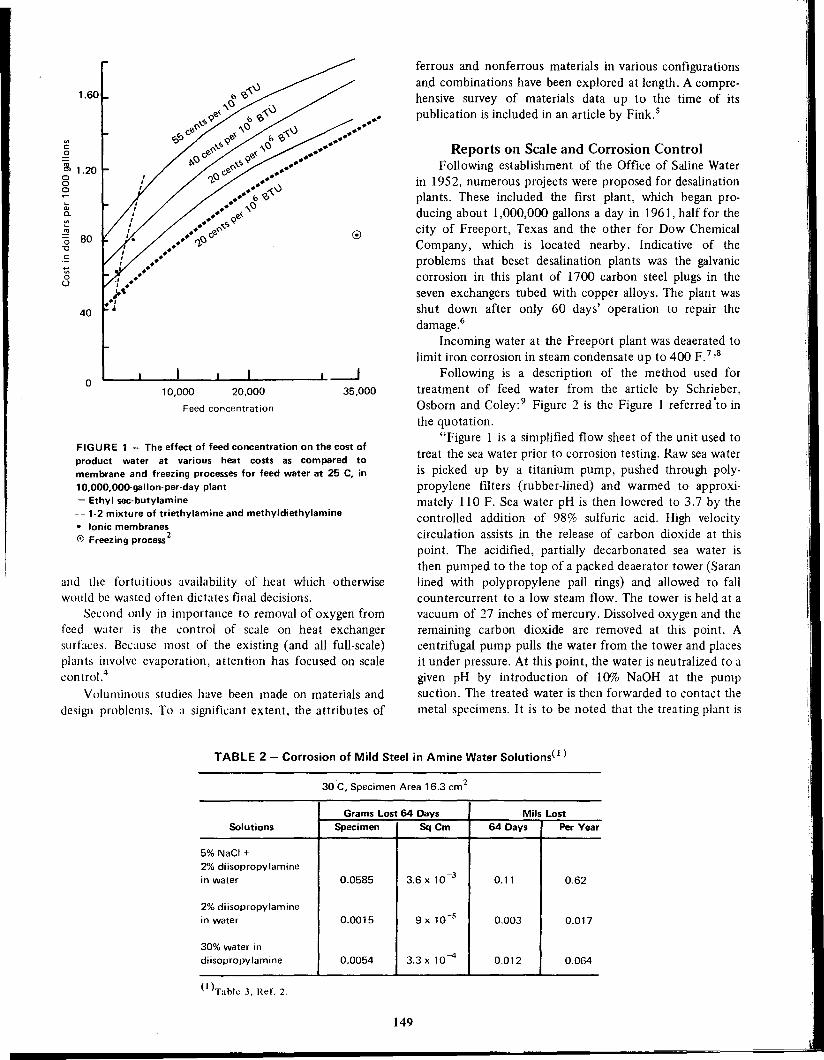
FIGURE 1 - The effect of feed concentration on the cost of
product water at various heat costs as compared tomembrane and freezing processes for feed water at 25 C, in10,OOO,OOO-gallon-per-dayplant- Ethyl sec-butylamine- - 1-2 mixture of triethylamine and methyldiethylamine• Ionic membraneso Freezing process2
and the fortuitious availability of heat which otherwisewould be wasted often dictates final decisions.
Second only in importance to removal of oxygen fromfeed water is the control of scale on heat exchangersurfaces. Because most of the existing (and all full-scale)plants involve evaporation, attention has focused on scalecontrol.4
Voluminous studies have been made on materials and
design problems. To a significant extent, the attributes of
ferrous and nonferrous materials in various configurationsand combinations have been explored at length. A comprehensive survey of materials data up to the time of itspublication is included in an article by Fink.s
Reports on Scale and Corrosion ControlFollowing establishment of the Office of Saline Water
in 1952, numerous projects were proposed for desalinationplants. These included the first plant, which began producing about 1,000,000 gallons a day in 1961, half for thecity of Freeport, Texas and the other for Dow ChemicalCompany, which is located nearby. Indicative of theproblems that beset desalination plants was the galvaniccorrosion in this plant of 1700 carbon steel plugs in theseven exchangers tubed with copper alloys. The plant wasshut down after only 60 days' operation to repair thedamage.6
Incoming water at the Freeport plant was deaerated tolimit iron corrosion in steam condensate up to 400 F.7 ,8
Following is a description of the method used fortreatment of feed water from the article by Schrieber,Osborn and Coley: 9 Figure 2 is the Figure I referred 'to inthe quotation.
"Figure I is a simplified flow sheet of the unit used totreat the sea water prior to corrosion testing. Raw sea wateris picked up by a titanium pump, pushed through polypropylene filters (rubber-lined) and warmed to approximately 110 F. Sea water pH is then lowered to 3.7 by thecontrolled addition of 98% sulfuric acid. High velocitycirculation assists in the release of carbon dioxide at this
point. The acidified, partially decarbonated sea water isthen pumped to the top of a packed deaerator tower (Saranlined with polypropylene pall rings) and allowed to fallcountercurrent to a low steam flow. The tower is held at a
vacuum of 27 inches of mercury. Dissolved oxygen and theremaining carbon dioxide are removed at this point. Acentrifugal pump pulls the water from the tower and placesit under pressure. At this point, the water is neutralized to agiven pH by introduction of 10% NaOH at the pumpsuction. The treated water is then forwarded to contact the
metal specimens. It is to be noted that the trea ting plan t is
--.J35,000
•••••••••••••••••••••
20,000
Feed concentration
10,000
~Q.)Cl.'"~.!!!'0 80"C~•...:5()
1.60
40
o
'"c.2
~ 1.20ooo
TABLE 2 - Corrosion of Mild Steel in Amine Water Solutions(l)
30 C, Specimen Area 16.3 cm2
SolutionsGrams Lost 64 Days
Specimen I Sq Cm
Mils Lost
64 Days I Per Year
5% NaCI +2% diisopropylaminein water 0.0585 3.6 X 10⁻³ 0.11 0.62
2% diisopropylaminein water 0.0015 0.003 0.017
30% water indiisopropylamine 0.0054 3.3x 10⁻⁴ 0.012 0.064
(I )Table J, ReI'. 2.
149

FIGURE 2 - Simplified flow sheet of sea water treating
facility.9
constructed entirely of material that will not allow metalions to enter the sea water stream."
6350 8200415
5001315
16650
4114
1352910
310019600
231003.0
5.035400
42000
7.8
8.3
Parts per Million
Guantanamo I KuwaitItem
(I )Table I, Reference 10.
pH
Hardness (CaC03)Calcium (Ca)
Magnesium (Mg)
P - Alk (CaC03)
M - Alk (CaC03)Sutfate (S04)Chloride (Cl)
Silica (Si02)Total solids
Scale formation is partially controlled by the additionof 3 to 5 ppm polyphosph,ate at brine concentration factorsof 1.5 to 2. An adherent sludge forms on heat transfersurfaces, however.
Corrosion Problems at 110, PeruHeavy chlorination at 1.5 ppm of feed water at the 110,
Peru, plant built there in I%6 for the Peru CopperCompany caused corrosion problems. I 1 The chlorinationwas done to offset the effects of pollu tion effluen t from a
fish meal plant, bird sanctuary wastes as well as frequent"red tides" and other marine growth. Reduced concen tration of chlorine and chlorination at intervals instead of
continuously decreased corrosion.
Inhibition of Mild Steel Corrosion
Phosphate-chromate mixtures were tested to limitcorrosion of mild steel under desalination conditions
at 250 F (121 C). When sea 'water was deaerated and atnearly neutral pH, mild steel had acceptably low corrosionrates using chromate or dichromate plus phosphate inhibitors. 12
During two week tests at 250 F using various coneen-
TABLE 3 - Analyses of Sea Water atGuantanamo Bay and Kuwait( I)
Inhibition of Kuwait EvaporatorPolyphosphate treatment of Caribbean or Mediter
ranean sea water is not as effective as it is in ocean waters
of the temperate zone. The Kuwait 1,200.000 gpd multi-. stage evaporators are operated at ]94 F with a brineconcentration of 2 and polyphosphate feed at :; ppnl.! ()This treatment results in a brine heater cleaning interval of8000 to 10,000 hours. Inhibited hydrochloric acid is used
for cleaning.
Although salt concentratj~n and alkalinity of the RedSea water is less than that at Guantanamo, the Kuwaitevaporators operate at higher brine concentrations and haveless sludge formation.
Effectiveness of treatment at Kuwait is attributed to
absence of iron in evaporator makeup water. Table 3 showscompositions of water from tile two sites.
150
To testingsystemsI DeaeratorAcid mixer
Steam
Filter
Raw, sea water intake
Other Evaporative PlantsThe plant at Point Loma (San Diego, California) was
operated for 26 months at 200 F10 with polyphosphatetreatment and at temperatures up to 250 F with acid
treatment. In February, 1964, 28 stages of the Point Lomaplant were shipped to Guantanamo Bay, Cuba, to supplywater to the D.S. garrison there after Cuba threatened tocut off its water supply. The eight stages (25 to 32) notsent to Cuba had steel tubing that showed signs ofcorrosion, while the cupronickel and aluminum brass tubingof the other stages had performed satisfactorily.
The three evaporators at Guantanamo Bay had anoutput rating of 2,250,000 gpd. Three 650 psi, 850 Fboilers supply steam for two condensing 7500 KW turbogenerators equipped with ftxed extraction bleed points.Turbine extraction steam supplemented by boiler steam isused for the brine heaters. Approximately 2 to 3 ppm of apolyphosphate is used for sea water treatment for theevaporators and sulfuric acid is added continuously forcleaning purposes.
In spite of the inhibitor treatment, an adherent sludgeforms. At Guantanamo Bay, the sludge is removed aboutonce a week from heat transfer surfaces by acid cleaningwhile the plant is operating. At Point Loma, cleaning isdone about once a month. Occasionally sulfamic acid isused but ordinarily sulfuric acid is fed continuously to theevaporator makeup to lower the pH of recycled brine toabout 5 or 5.5.
After three of the steel water boxes at Guantanamo
developed leaks, they were re-installed after a stainless steelliner was applied over their exposed surfaces.
Sulfuric acid is introduced into the sea water' makeupat the Lanzarote, Canary Islands evaporator to help controlscale. 1 0 Carbon dioxide and air are removed in the last
stage by a steam jet vacuum system and pH of recycled seawater is controlled to a range of 7.6 to is. A concentrationfactor of 2 is maintained.

trations and proportions, chromate-phosphate inhibitorsreduced corrosion rates from 49 mils per year to 4 or 5 insome tests. Figure 3 shows some of the r~sults.
Best results were obtained with 5 ppm chromate plus30 to 45 ppm phosphate as monosodium dihydrogenphosphate. It was recognized that this method creates theproblem of disposal of the poisonous wastes or theirneutralization before returning residual water to the ocean.
Another way to decrease the cost of desalination is tomodify sea water so that it no longer is highly corrosive toinexpensive materials of construction such as mild steel oreven aluminum. W. H. McCoy13 said that in 1965,corrosion control in sea water had been achieved by the useof organic monolayers and controlled multilayers. Longchain, branched and unbranched amines and long-chainacids are representative of materials tried. The best inhibitor tested was a mixture of stearic acid and n-octadecylamine.
The Dow Chemical Company, under Office of SalineWater sponsorship, initiated in its laboratories in 1967, aprogram designed to explore the possibility of employingenvironmental changes to permit the economic use of mildsteel or aluminum as materials of construction for heatexchanger surfaces in desalination plants. The first reporton this program pointed out that efficient exclusion ofdissolved oxygen from sea water will permit the use of mildsteel at temperatures up to 250 F. Contamination of thewater with even traces of dissolved oxygen, however, is
FIGURE 3 - Corrosion rate of mild steel versuschromat.phosphate ion concentration after two weeks'exposure in oxygen seturated see water at 250 F (121 Cl.
Total chromate-phosphate (1:1) concentration (ppm)
Inhibition of Aluminum AlloysDissolved oxygen was found not to exert a pronounced
effect on the corrosion of aluminum alloys in sea water at250 F. Of five aluminum alloys tested, only one, 5052,demonstrated a high level of resistance when no inhibitorwas used. Other alloys tested were 1l00, 3003, 5554, and6061. Bicarbonate ion at 50 ppm concentration permits theuse of 1100 alloy in desalination applications when the pHis adequately controlled. Chromate ion at 100 ppmconcentration confers excellent corrosion resistance toalloys 1100, 3003, and 5554 in sea water at 250 F. Portionsof this report covering mild steel results were published in1970.15 All early results were obtained in laboratory tests.
Data only recently available from the AluminumAssociation test unit at OSWFreeport Test Facility indicatethat certain aluminum alloys may be perfectly acceptablefor use in desalination plants without the use of anyinhibitor. Later Dow work14 reported that a chromatebicarbonate inhibitor controlled corrosion and pitting of1l00, 3003, 5052, 5554 and 6061 aluminum alloys. Inmost cases, this meant low rates were decreased to evenlower values. In a dynamic test involving the 1100 alloy,the corrosion rate decreased from 100 to 1 mpy. The
sufficient to cause a localized attack that is prohibitive evenat low overall corrosion rates.
Three inorganic inhibitor systems described provideeffective corrosion control in oxygen saturated sea water at250F.
1. A dichromate-phosphate used at a concentration of50 ppm,
2. A chromate-phosphate used at a concentration of50 ppm and
3. A chromate-phosphate-zinc-iodide system used at aconcentration of 100 ppm.
Later results obtained in the Dow program14 designedto modify the sea water environment revealed that lowlevels of dissolved oxygen plus low levels of chromate plusphosphate inhibitor offer excellent promise of controllingmild steel corrosion in a hot sea water environment.Chromate may be supplied with equal effectiveness aseither sodium chromate or sodium dichromate. Of com
mercial phosphates tested, only NaH2P04 (sodium dihydrogen phosphate) and Na2HP04 (disodium hydrogenphosphate) were acceptable sources of phosphate anion inthe chromate-phosphate inhibitor. Na2HP04 is preferredbecause it did not cause pitting.
Specific commercial phosphate compounds that werenot acceptable as sources of phosphate ion includedtrisodium phosphate, sodium tripolyphosphate, sodiumhexametaphosphate, sodium pyrophosphate, sodium metaphosphate. Some of these materials were acceptable whentested as reagent grade chemicals, but Na2HP04 is alwaysthe preferred source. Dynamic loop tests with 1 ppmchromate plus 9 ppm phosphate without oxygen addition,but also without deaeration, indicate that even this lowconcentration may be effective. Even lower concentrationsmay be satisfactory in an effectively deaerated system.
500400300200
(Figure 1, Reference 12)
100o
20
10
>Q.E
30
40
60
151

FIGURE 4 - Comparison of static and dynamic corrosionrates of AI in treated 250 F sea water. 1 7
mixture of chromate and bicarbonate is definitely superioras a corrosion inhibitor to either used alone. Most of the
later Dow work has been presented at various nationalNACE meetingsI ',16,1 7 (Figure 4).
If the bicarbonate naturally present in sea water isactive as the bicarbonate source in the chromate-bicarbonate inhibitor and if the concentration of bicarbonate
required for inhibition does not cause scaling, the cost ofinhibitor addition can be extremely low (on the order of
one cent per thousand gallons of water. produced). Thiscould be inexpensive if it would truly guarantee againstfailure of aluminum components in desalination processes.
It should be emphasized that only additional testingwill determine if these inhibitor systems actually willfunction under real desalination conditions. They have justpassed from the research stage, so time will be required toascertain if the inhibitor approach will make a significantcontribution to decreasing the cost of desalinated water bypermitting the use of less costly materials. If inhibitors
continue to show progress, ecological considerations mayrequire development of methods for their removal from the
brine concentrate leaving the desalination plant or ideallypermit their re-use.
Removal of Carbonates
Removal of carbonates would allow the systems to
function without serious scaling at temperatures up to 260to 270 F. The next generation of plants is planned foroperation at temperatures of 325 to 350 F because aproduction plant that operates at these higher temperatureswould have much lower costs due to improved thermodynamic performance. Operation at these temperatures willrequire removal of significant percentages of the calciumand magnesium ions from sea water to prevent sulfatescaling.
Three methods are currently under investigation forconditioning feed water so that distillation temperaturescan be increased without serious scale problems. TheMason-Rust Company, at the Wrightsville Beach TestFacility, is treating decarbonated sea water with a barium
type cation-exchange resin both to absorb Na, Ca and Mgcations and to precipitate sulfate as barium sulfate.I8 Thisallows a multi-stage flash evaporator unit to operate up to335 F. The San Diego Test Facility is using a limemagnesium-carbonate scale control pilot plant to conditionfeed water for higher temperature operations. 1 9 TheMaterials Test Center of Freeport Test Facility will soon
have on stream a cation-exchange facility for removingsignificant portions of the calcium and magnesium from thewater, thus allowing the use of higher temperatures. Asimilar process is described in the 1969-1970 Saline Water
Conversion Report by Chemical Separations Corporation.20
Miscellaneous Corrosion ProblemsOther corrosion problems, solutions for some of which
are still lacking, include attacks by residual ammonia.Because ammonia is in an ionized, chemically bound state,
Use of Chelating AgentsAnother method of control is to add chemicals that
prevent scale deposition on heat exchange surfaces. Thiscan be done using "seed crystals" that cause precipitationof the scale-forming compounds in the brine and cause theinsoluble precipitant to go out with the effluent rather thandeposit in unwanted places. This also can be done withchelating agents that hold the troublesome ions in solution.
An excellent review of materials tried in various desaltingplants to control scale formation by addition of variouschemicals is presented in a 1969 OSW report2 1 and will notbe repeated here. Several articles on scale control methodsof various kinds were presented to the First InternationalSymposium on Water Desalination.1 3
Other methods that have been investigated for controlling scale include utilization of graphite heat transfertubes of controlled permeability to steam22 ,23 to keep thesolution adjacent to the tube wall below the saturation orsupersaturation temperature and concentration limitsrequired for scale formation. Another method is to determine the effect of surface potential on the formation ofcalcium sulfate scale.24 The latter work was done on a
research basis utilizing controlled potentials on platinumelectrode surfaces where it was found that surface potentialdoes affect nucleation of calcium sulfate scale.
152
-----• --I ---;;;; •--- I-- -- -- •-• - -• - I-- -- --50/50
5/50
SCALE
STATIC DEAERATED
CHANGE XO.5
-. - STATIC O2 SATURATED
111I111I1 DYNAMIC
ppm Ratio: Cr04'/HCO;
LC'l0mpy
""0cO
cO
It----
•••-------------------------• --•---I ---• --I ---- --I ---• --I ---• --I ---•--I ----- -I ----• -I ------- ---
BLANK
4
o
2
3
5
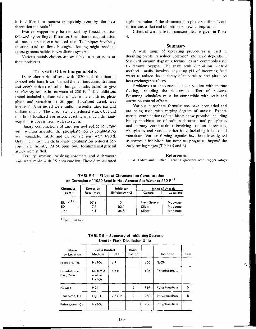
TABLE 4 - Effect of Chromate Ion Concentrationon Corrosion of 1020 Steel in Hot Aerated Sea Water at 250 F 14
Name Scale ControlCone.
or Location
MediumpHFactorFInhibitorppm
Freeport, Tx.
H2S043.7 250NaOH
Guantanamo
Sulfamic5-5.5 195Polyphosphate
Bay, Cuba
acid or
H2S04Kuwait
HCI 2194Polyphosphate 5
Lanzarote, C.1.
H2S047.6-8.22250Polyphosphate 5
Point Loma, Ca.
H2S04 250Polyphosphate
153
Moderate
Moderate
Moderate
Mode of AttackGeneral I Localized
Very Severe
Slight
Slight
References1. A. Cohen and L. Rice. Recent Experience with Copper Alloys
4.
again the value of the chromate-phosphate solution. Localaction was stifled and inhibition somewhat improved.
Effect of chromate ion concentration is given in Table
SummaryA wide range of operating procedures is used in
desalting plants to reduce corrosion and scale deposition.Standard vacuum degassing techniques are commonly usedto remove oxygen. The main scale deposition controlmethod usually involves adjusting pH of incoming feedwater to reduce the tendency of minerals to precipitate onheat exchanger surfaces.
Problems are encountered in connection with marine
fouling, including the deleterious effect of poisons.Poisoning schedules must be compatible with scale andcorrosion control effects.
Various phosphate formulations have been tried andare being used with varying degrees of success. Experimental combinations of inhibitors show promise, includingbinary combinations of sodium chromate and phosphatesand ternary combinations involving sodium chromates,phosphates and various other ions, including iodates andvanadates. Various filming organics have been investigatedas corrosion inhibitors but none has progressed beyond theearly testing stages (Tables 5 and 6).
o92.195.8
Inhibitor
Efficiency (%)
97.87.64.1
TABLE 5 - Summary of Inhibiting SystemsUsed in Flash Distillation Units
Corrosion
Rate (mpy)
Chromate
(ppm)
Blank{ I)
50100
{I )No inhibilor.
Tests with Other Inorganic SaltsIn another series of tests with 1020 steel, this time in
aerated solutions, it was learned that various concentrationsand combinations of other inorganic salts failed to givesatisfactory results in sea water at 250 F.' 2 The inhibitorstested included sodium salts of dichromate, nitrite, phosphate and vanadate at 50 ppm. Localized attack wasincreased. Also tested were sodium arsenite, zinc ion andsodium silicate. The chromate ion reduced attack but did
not limit localized corrosion, reacting in much the sameway that it does in fresh water systems.
Binary combinations of zinc ion and iodide ion, zincwith sodium arsenite, the phosphate ion in combinationwith vanadate. nitrite and dichromate ions were tested.
Only the phosphate-dichromate combination reduced corrosion significantly. At 50 ppm, both localized and generalattack were stifled.
Ternary systems involving chromate and dichromateions were made with 25 ppm zinc ion. These demonstrated
it is difficult to remove completely even by the best. deaeration methods. 1 1
Iron or copper may be removed by forced aerationfollowed by settling or filtration. Chelation or sequestrationof trace elements can be used also. Techniques involvingchlorine used to limit biological fouling might produceexcess gaseous halides in ventilating systems.
Various metals choices are available to solve some of
these problems.
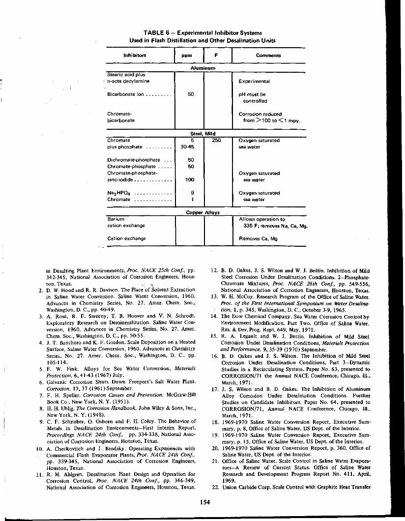
TABLE 6 - Experimental Inhibitor SystemsUsed in Flash Distillation and Other Desalination Units
in Desalting Plant Environments, Proc. NACE 25th Conf, pp.342-345, National Association of Corrosion Engineers, Hous-ton, Texas. ';
2. D. W. Hood and R. R. Davison. The Place 'of Solvent Extractionin Saline Water Conversion. Saline Water Conversion, 1960.Advances in Chemistry Series, No. 27. Amer. Chem. Soc.,Washington, D. c., pp. 40-49.
3. A. Rose, R. F. Sweeny, T. B. Hoover and V. N. Schrodt.Exploratory Research on Demineralization. Saline Water Conversion, 1960. Advances in Chemistry Series, No. 27. AIDer.Chem. Soc., Washington, D. C., pp. 50-55.
4. J. T. Banchero and K. F. Gordon. Scale Deposition on a HeatedSurface, Saline Water Conversion, 1960. Advances in ChemistrySeries, No. 27. Amer. Chem. Soc., Washington, D. C., pp.105-114.
5. F. W. Fink. Alloys for Sea Water Conversion, MaterialsProtection. 6,41-43 (1967) July.
6. Galvanic Corrosion Shuts Down Freeport's Salt Water Plant.Corrosion, 17,37 (1961) September.
7. F. H. Speller. Corrosion Causes and Prevention. McGraw-HillBook Co., New York, N. Y. (1951).
8. H. H. Uhlig. The Corrosion Handbook. John Wiley & Sons, Inc.,New York, N. Y. (1948).
9. C. F. Schrieber, O. Osborn and F. H. Coley. The Behavior ofMetals in Desalination Environments-First Interim Report,Proceedings NACE 24th Conf. pp. 334-338, National Association of Corrosion Engineers, Houston, Texas.
10. A. Checkovitch and J. Brodsky. Operating Experiences withCommercial Flash Evaporator Plants, Proe. NACE 24th Conf.pp. 339-345, National Association of Corrosion Engineers,Houston, Texas.
11. R. M. Ahlgren. Desalination Plant Design and Operation forCorrosion Control, Proc. NACE 24th Conf, pp. 346-349,National Association of Corrosion Engineers, Houston, Texas.
Allows operation to335 F; removes Na, Ca. Mg.
Removes Ca, Mg
Comments
Experimental
Oxygen saturatedsea water
pH must becontrolled
Oxygen saturatedsea water
Oxygen saturatedsea water
Corrosion reducedfrom> 100 to < 1 mpy.
F
12. B. D. Oakes, J. S. Wilson and W. J. Bettin. Inhibition of MildSteel Corrosion Under Desalination Conditions. 2-PhosphateChromate Mixtures, Proc. NACE 26th Conf, pp. 549-556,National Association of Corrosion Engineers, Houston, Texas.
13. W. H. McCoy. Research Program of the Office of Saline Water.Proc. of the First International Symposium on Water Desalination, I, p. 345, Washington, D. C., October 3-9, 1965.
14. The Dow Chemical Company. Sea Water Corrosion Control byEnvironment Modification. Part Two. Office of Saline Water.Res. & Dev.Prog. Rept. 649. May, 1971.
15. R. A. Legault and W. J. Bettin. Inhibition of Mild SteelCorrosion Under Desalination Conditions, Materiols Protectionand Performance. 9, 35-39 (1970) September.
16. B. D. Oakes and J. S. Wilson. The Inhibition of Mild SteelCorrosion Under Desalination Conditions, Part 3-DynarnicStudies in a Recirculating System. Paper No. 63, presented toCORROSION/71 the Annual NACE Conference, Chicago, Ill.,March,1971.
17. J. S. Wilson and B. D. Oakes. The Inhibition of AluminumAlloy Corrosion Under Desalination Conditions. FurtherStudies on Candidate Inhibitors. Paper No. 64, presented toCORROSION/71, Annual NACE Conference, Chicago, Ill.,March,1971.
18. 1969-1970 Saline Water Conversion Report, Executive Summary, p. 8, Office of Saline Water, US Dept. of the Interior.
19. 1969-1970 Saline Water Conversion Report, Executive Summary, p.15, Office of Saline Water, US Dept. of the Interior.
20. 1969-1970 Saline Water Conversion Report, p. 360, Office ofSaline Water, US Dept. of the 'Interior.
21. Office of Saline Water. Scale Control in Saline Water Evaporators-A Review of Current Status. Office of Saline Water
Research and Development Progress Report No. 411, April,1969.
22. Union Carbide Corp. Scale Control with Graphite Heat Transfer
154
91
Aluminum
5050
50
Copper Alloys
100
ppm
Steel. Mild
5 I 25030-45
Cation exchange
Bicarbonate ion .
Inhibitors
Bariumcation exchange
Dichromate-phosphate .Chromate-phosphate .Chromate-phosphate-zinc-iodide .
Chromateplus phosphate
Chromatebicarbonate
Stearic acid plusn"octa decylamine

Tubes of Controlled Permeability to Steam. Office of SalineWater Research and Development Progress Report. No. 272,July, 1967.
23. Union Carbide Corp. Scale Control with Graphite Heat TransferTubes of Controlled Permeability to Steam, Phase 11.Office ofSaline Water Research and Development Progress Report No.396, October, 1968.
24. TRW, Inc. Effect of Surface Potential on Scale Formation.Office of Saline Water Research and Development ProgressReport No. 393, January, 1969.
25. J. S. Wilson and B. D. Oakes. The Inhibition of AluminumAlloy Corrosion Under Desalination Conditions. 2-FurtherStudies of Candidate Inhibitors, Proc. 27th Con[., NationalAssociation of Corrosion Engineers, 1971, Paper No. 64.
BibliographyNew Water. A booklet published by the Office of Saline Water, US
Dept. of the Interior, Washington, D. C.M. S. Sachs. Desalting Plants Inventory, Report No. 2, US Dept. of
the Interior, Washington, D. c., January 1,1969.Arthur D. Little, Inc. Survey of Materials Behavior in Multi-Stage
Flash Distillation Plants. Report to the Office of Saline Water,US Dept. of thc Interior, Washington, D. c., August, 1968.
E. H. Newton and J. D. Birkett, Arthur D. Little, Inc. SummaryReport on Survey of Material.s Behavior in Multi-Stage FlashDistillation Plants. Presented at a Symposium sponsored byOffice of Saline Water, US Dept. of the Interior, Washington, D.c., Scptember 25, 1968.
W. L. Badger and Associates, Inc. Operation of Pilot Plant LTVEvaporator at Wrightsville Beach, N. c., Office of Saline WaterResearch and Dcvelopment Report No. 26, December, 1959.
Stcarns-Rogers Manufacturing Co. First Annual Report, SalineWatcr Dcmonstration Plant No. I, Freeport, Texas. Saline WaterConvcrsion Progress Report No. 71, Office of Saline Water,January, 1963.
Battcllc Mcmorial Institute. Investigation of Corrosion in Hot SeaWatcr in an Experimental Loop Apparatus. Office of SalineWater Rcsearch and Development Progress Report No. 225,Dcccmber, 1966.
C. F. Schricber, O. Osborn and F. H. Coley. Corrosion of Metals in
155
Desalination Environments, Materials Protection, 7, 20 (1968)October.
The Dow Chemical Co. Sea Water Corrosion Test Program, Office ofSaline Water Research and Development Progress Report No.417, March, 1969.
A. Cohen and L. Rice. Recent Experience with Copper Alloys inDesalting Environments, Materials Protection, 8, 67 (1969)December.
The Dow Chemical Co. Sea Water Corrosion Control by Environment Modification. Office of Saline Water Research andDevelopment Progress Report No. 438, April, 1969.
A. Cohen and L. Rice. Experience with Copper Alloys in theDesalting Environment, Materials Protection and Performance,9, 29 (1970) November.
A. Cohen and L. Rice. Copper and Its Alloys in the DesaltingEnvironment- Third Progress Report. Paper No. 57 presented toCORROSION/71, Annual NACE Conference, March, 1971.
The Dow Chemical Co. Sea Water Corrosion Test Program: PartTwo. Office of Saline Water Research and DevelopmentProgress Report. No. 623. Dec., 1970.
E. D. Verink, Jr. Aluminum Alloys for Desalination Service,Materials Protection, 8, 13 (1969) November.
E. D. Verink, Jr. Performance of Aluminum Alloys in DesalinationService-A Progress Report. Paper No. 60 presented to CORROSION/71, Annual NACE Conference, Chicago, Ill., March,1971.
T. R. Harkins and H. H. Lawson. Evaluating the Performance ofStainless Steels in Desalination Plant Environments, Proc. 25thNACE Conference, p. 600, Philadelphia, Pa., March, 1970.
T. R. Harkins and H. H. Lawson. Performance of Stainless Steels in
Desalination Plants, Water and Wastes Eng. (1970) January.T. R. Harkins and H. H. Lawson. Evaluating Material Performance in
3000 gpd Stainless Steel Desalination Test Plant-One YearOperation. Paper No. 58 presented to CORROSION/71, AnnualNACE Conference, Chicago, Ill., March, 1971.
Westinghouse Electric Corp. Development of a Low-Cost Iron-BaseAlloy to Resist Corrosion in Hot Sea Water. Office of SalineWater Research and Development Progress Report No. 394,January, 1969.
Westinghouse Electric Corp. Development of a Low-<::ost Iron-BaseAlloy to Resist Corrosion in Hot Sea Water. Office of SalineWater Research and Development Progress Report No. 478,September, 1969.

GEORGE GARDNER*
Inhibitors in Acid Systems
IntroductionCorrosive solutions in the acidic range are more commonlyencountered in industry than are solutions nominallyneutral or alkaline. The importance of inhibitive practicesin acidic solutions is increased by the fact that iron and itsalloys constitute the bulk of exposed metals in industrialand other environments and because iron is more
susceptible to attack in the acidic pH range than it is in thealkaline range.
Emphasis in this chapter, therefore, will be on the effectof acids on ferrous metals. This does not infer that acidicenvironments do not also result in the corrosion of
nonferrous metals. It does, however, acknowledge that thefrequency and magnitude of corrosion problems involved inhandling acids with ferrous metals overshadows the problems faced when other metals are used.
At various places elsewhere in this book, inhibitorpractices aimed at mitigation of acid attack on metals arementioned. Consequently, those interested in acidic environments will find it helpful to use the subject index ofthis book to locate additional information on acidiccorrosion.
Industrial Exposures of Metals to AcidsMetals are exposed to the action of acids in many
different ways and for many different reasons. Theexposures can be most severe but in many cases, thecorrosion can be controlled by means of inhibitors.
Processes in which acids play a very important part are:
Acid Pickling
In these processes, undesirable oxide coatings areremoved from metals~usually ferrous metals-and thesurface is prepared for further operations, such as phosphate coating, enameling, electroplating, painting, etc. Theacid of choice has for many years been sulfuric acid. Thishas been gradually changing to hydrochloric acid, especiallyin large scale continuous operations such as metal strippickling. Other acids, such as nitric and hydrofluoric havespecial uses for treating alloy steels. Organic acids aresometimes used for metal pickling, but they are not usuallysatisfactory for removal of heavy scales or deposits.
Uninhibited pickling solutions are wasteful in terms ofbase metal unnecessarily dissolved and in the acid con-
·Corrosion Specialist, Elkins, Pa.
156
sumed by the attack on the base metal. In a typicalapplication, inhibitors, by localizing attack on scale in a200 F sulfuric acid bath reduced metal lost from 102 Ib in5 minutes and 390 Ib in 15 minutes in an uninhibited bathto 0.5 Ib in 5 minutes and 21b in 15 minutes in an inhibitedbath. The inhibitor also reduced fumes and spray bylimiting the amount of hydrogen gas produced. Because lessacid is consumed in an inhibited bath, the effectiveness ofthe bath is extended.)
In some cases, both sulfuric and phosphoric acid areused in pickling baths, the phosphoric acid providing aresidual iron phosphate layer which is suitable for subsequent coating.
Inhibitors are extensively used in metal pickling andvary in type according to the acid used in the picklingoperation.
Industrial Acid Cleaning
This very important procedure is applied chiefly to theremoval of scale and other unwanted deposits from steamgenerating equipment and from chemical and petrochemicalreaction vessels. Hydrochloric acid is widely used, frequently with an important assist from hydrotluoric acid orfluorides.
Next in importance for this service is the group oforganic acids consisting of citric and a mixture of hydroxyacetic and formic and less frequently of acetic, oxalic andtartaric acids. Sulfuric and phosphoric acids also are usedfor chemical cleaning, but less frequently than hydrocWoric.
A cationic blend of nitrogen-containing ingredien ts hasbeen used successfully to con trol corrosion of boilerscleaned by citric acid? Citric acid is preferred for austeniticsteels and copper alloys. A 3% citric acid solution, pHadjusted to 3.5 with ammonia, is used to remove magnetite.Ammonium bifluoride may be added up to 1.5% at not lessthan 85 C if the deposits are very hard.
Tests showed that at 74 C, concentrations of inhibitorat 0.03% reduced corrosion rates in 5, 10 and 20% acid
from 0.1 to a little more than 0.001 mgfcm2/day, rates atall three concentrations clustered about the same point. At95 C, under the same conditions, results were more
scattered, the rate for 10% acid being reduced from 0.1mgfcm2/day for the uninhibited control to a little less than0.01 mgfcm2/day in 5% acid; with slightly increasedcorrosion rates for the 10 and 20% concentrations. Rates of

all three at 95 C were less than 0.01% for 0.03% inhibitorconcentration.
Qeaning of Oil Refinery EquipmentMaximum temperature for inhibited hydrochloric acid
used for cleaning cast iron in petroleum refinery equipmentis 125 F, while other metals can be cleaned safely at 170 F,according to Walston and Dravnieks.3 Using 7.5% acid at170 F caused graphitization of some cast irons, particularlythose with combined carbon.
In cleaning systems that include stainless steel, extremecare must be used to assure that all the acid is thoroughlyflushed from the system because retained chloride ions willcause disastrous stress corrosion cracking. Copper, platingout on steel surfaces from ions dissolved from coppertubing in heat exchangers, is another hazard of circulatingcleaning procedures. Copper ions react with the iron in anoxidation reduction reaction against which most inhibitorsare ineffective.
Production of explosive and poisonous gasesis a hazardin acid cleaning. Hydrogen gas must be vented andprecautions taken against fire and sparks. Hydrogen sulfide,hydrogen cyanide, arsine and phosphine have been found invessels being cleaned. Neutralization of these gases bycaustic or burning or venting to the atmosphere isnecessary.
Because ferric ions accelerate corrosion by cleaningsolutions, a limit of 0.4% by weight usually is the"accepted" maximum. A 1% solution of ferric ions hasbeen known to increase the corrosion rate by a factor ofnine.
Table 1 shows some of the results achieved with various
inhibitors in reducing corrosion rates of refinery equipmentfrom acid cleaning solutions.
Stannous chloride, lead nitrate and lead acetate havebeen tested in efforts to reduce accelerated corrosion thatsometimes occurs in crevices; however, they are ineffectivein the presence of hydrogen sulfide. Accelerated attack alsomay occur because of galvanic couples between metalsdiffering in their solution potentials. Low carbon steel was0.031 mv positive to Type 304 steel in one test.3
A report of NACE Technical Unit Committee 8A4
points out that spent acid from one cleaning operationshould not be used in another cleaning operation because ofpossible bad effects from concentrations of cupric or ferricions in the used solution. The report contends that allstainless steel systems can be cleaned effectively usingsulfuric or nitric acid solutions. Stainless steels that havereached their sensitization temperature are likely to sufferintergranular attack.
Heat ExchangersBy injecting hydrochloric acid solution of 1-2N concen
tration and containing a commercial inhibitor directly intocooling water immediately before it enters an operatingheat exchanger, the exchanger can be cleaned on-stream.This procedure, reported by Koehler,5 exposes the coppertubing to the acid for severalminutes with no apparent badeffect. Scale removed by the treatment along with residualacid is recirculated in the system with no apparent badeffect, probably because of the large volume of coolingwater in the system.
Inhibitors are very important in chemical cleaning andtheir selection and use are important ingredients in asuccessfuljob.
Oil Well Acidizing
For oil well stimulation, large quantities of acidusually hydrochloric-are pumped at high rates of flowthrough the oil well tubing into the producing formation.The primary object is to act on the formation in such a wayas to stimulate the oil flow. If the nature of the formationrequires it, hydrofluoric acid is added to the hydrochloricacid.
Oil well acidizing represents a severe test for inhibitors.The acid concentrations are high-usually 10 to 15%HCl byweight and at times 28%. Temperatures at the bottom ofthe hole can be as high as 177 C (350 F).
Effects of agitation, exposure, time, acid type andconcentration and inhibitor concentration at 100 to 350 Fare reported by McDougal1.6 The influence of temperatureon corrosion rates of N-80 oil well tubing tested ininhibited 15% hydrochloric acid is shown in McDougall'sTable 4.6 Corrosion rates in solutions with 0.1 volume
TABLE 1 - Influence of Inhibitors in 5% Hydrochloric Acidon Rates of Dissolution of Iron Oxides and Sulfides( I)
% Inhibition in Dissolution of:FreeLowC
MachiningInhibitor
ISteel SteelFeSFe~FeOFe304-C
66 715H13-170B
98.299.750I-I3812A
99 99.923I-I62HD
98.5 -15I-I7510
Note: (-) sign indicates slight acceleration of dissolution.In the case of Fe304 in Inhibitor C, acceleration of dissolution as compared withplain 5% HCI was by 170%.
(I) All tests at 150 Fin 5% acid for 2 hours.
IS7

TABLE 2 - Composition, Types and Applicationsof Inhibitors for Acid Solutions
References for Table 21. Z. A. Foroulis. Aryl Substituted Aliphatic Aldehydes as
Corrosion Inhibitors. Esso Research and Engineering Co. V,S.3,530,059 (Cl. 208-47; C 23f), Sept. 22, 1970, Appl. May 17,1968. CA 74, 593u.
2. Z. A. Foroulis. p-Anisaldehyde as a Corrosion Inhibitor. V.S.3,537,974 (0. 208-47; C 23f) Nov, 3, 1970, Appl. July 2,1968. CA 74, 78081z.
3. M. N. Desai and S. M. Desai. Corrosion Inhibition of Aluminum
2S and 3S in Hydrochloric Acid, Werkstoffe Korrosion, 17, No.3,207-13 (1966). CA 64,17193,
4. G. W. Poling. Infrared Studies of Protective Films Formed by
percent concentrations of four out of five inhibitorsincreased dramatically between 66 C (150 F) and 93 C (200F). A typical result in these 24 hour tests was: InhibitorC-66 C, 0.0053 lb/fe /day and at 93 C, 0.0662Ib/ft2 /dayor about 2.5 times increase at the higher temperature.
Manufacturing ProcessesIn this very broad field, very little that is specific can
be said. Usually it is the intent of the manufacturer toselect reaction vessels from alloys that will be resistant toreactants and products in his process. If this is not feasible,other means must be used for protection, one of whichcould be the use of inhibitors.
It is usually desirable to select alloys that are resistantto acid to be stored. When this is not possible, it isnecessary to protect the metal (usually mild steel) by meansof a suitable inhibitor.
Vapor-Liquid Systems: Condensing VaporsOne of the most important examples of corrosion from
condensing acid vapors is that of combustion gases, whereS02 is converted to S03, which forms sulfuric acid byreacting with water condensed in the cooler zones of thecombustion equipment. Some attempts are being made nowto protect such zones by means of inhibitors.7-1 Z
Structures of Organic Compounds
Useful for Inhibiting AcidsStudies on the relation between the organic structure
of inhibitors and their effectiveness in acid systems havebeen made by numerous investigatorsl3-16 and summarized by Eldredge in Uhlig's Corrosion Handbook.1 7
Carrying this idea further, Doutyl8 classified organicinhibitors according to elemental composition andfunctional groups.
Table 2 is an arrangement that follows the classificationof Douty, with some extensions of his ideas. Classes ofinhibitors are shown, arranged according to their elementalcomposition. The references given are mostly recent andimply that the compounds cited have present-day interestas inhibitors.
Inorganic InhibitorsSome of the earliest inhibitors for acids were inorganic
compounds, although their use is not widespread today.Because many of the inorganic inhibitors come under theclassification of "dangerous" inhibitors according toEvans,19 the tendency to cause pitting is severe. Thefollowing outline covers inorganic compounds used mostoften as acid inhibitors:
ArsenicThe most extensive use of arsenic as an inhibitor for
acies is in acidizing oil wells with hydrocWoric acid. Undersome conditions, the protection can be very good; however,there always exists the possibility of at least three hazards:
1. Danger from the high toxicity of arsenic in solutionand of the arsine gas formed when acid acts upon metal inthe presence of arsenic.
Elemental
Composition
C,H,O
C,H,N
c;H,-s
C,H,N,O
C,H,S,O
C,H,N,S
C,H,S,N,O
Organic phosphorusCompounds
Organic compoundsof phosphorus andselenium
Organic compoundsof silicon
Organic hal ides
Compound
Aldehydes (furfural)
Acetylenic alcoholsand allenic alcohols
Organic acids
Pyrylium salts
Olefinic polymers
Pyridines, quinolines
P"olymethylene iminesOnium ions
Aliphatic amines
Anilines
Saturated and partially
saturated N-rings, such as
piperidines, pyrrolidines,
and pyrimidines.
Aldehyde-amine conden
sation products.
Cyano-ethylated amines
Vinyl pyridine polymers
Stearyt amine
Propargyl benzylamine
Organic sulfidesSulfonium compounds
Amino phenol derivativesEthylene oxide adducts of
abietyl amineQuinolinols
N-2-propynyl morphotine
Polymerized 4-hydroxypiperidines
Cyclic and heterocycllcketoamines
Dibenzyl sulfoxideXanthates
Aryl and alkyl sulfoxidesSulfonic acids
Thioureas
Organic thiocyanates
Thiazoles, thiazines
propylene oxide adducts ofthioureas
Dodecylpyridinium xanthate
Thiomorpholine, pneno·
thiazine, and derivativesSulfonated imidazolines, etc.Sulfoximines
Organic phosphorus compoundsPhosphonic acids
0,0,0, triethyl seleno
phosphate
Halogenated aromaticsChlorinated amines
Application References
Acids and H2 S.
1,2AI in HCI
3
Various acids
4-12
and metals Steel in Het13
Fe and Ni in HCI
14
Fe in HCI
15Fe in Hel and
16-18
H2S04
19-23
Fe in Hel24
Fe in Hel and
24-27
H2S04
14,28
AI, Mg in HCI
29,30Fe in Hel
30
AI in HCI
31
Steel in
various acids.
32
Mild steel in HCI33,34
Fe in H2S04
35
Fe in Hel36
Fe in acids
37
Fe in Hel38
Fe in H2S04
39,40Fe in various acids
41,42HCI
43
Various acids
4
Fe in HCI
45
Fe in acids
46
Fe in acids
47
Fe in acids
48
Fe in acids
49
Fe in acids
50
Fe in acids
51
Fe in acids
52
Fe in H2S04
53-56
AI and Mg in HCI
57
Fe in HCI
58
AI in acids
59
Fe in acids
60-63
Fe in HCI and H2S04
64,65
Fe in H?S04
66
Fe in H2S04 and citric acid
67
Fe in Hel
68
Fe in H3P04
69
Fe in HCI
70
Fe in HCI
71
AI in HCI
72
Fe in Hel
73
Fe in acids
74
Fe in acids
75
158

Acetylenic Corrosion Inhibitors, 1. Electrochem. Soc., 114, No.12,1209-14 (1967). CA 68, 8659w.
5. V. A. Khitrov and V. P. Zadorozhnyi. Some Characteristics ofPropargyl Alcohol as an Inhibitor of Steel Corrosion inHydrochloric Acid Solutions, Izv. Vyssh. Ucheb. Zaved., Khim.Khim. Tekhnol., 9, No. 5, 744-8 (1966). CA 66. 58292a.
6. N. J. Podobaev and A. G. Voskresenskii. Some OrganicCompounds with Ethylenic and Acetylenic Bonds Tested asInhibitors for the Acid Corrosion of Steel, Zh. Prikl. Khim., 43,No. 4, 834-8 (1970). CA 73, 37849s.
7. Clare H. Kucera. Dow Chemical Co. Corrosion Inhibitor forAqueous Hydrochloric Acid Solutions. U.S. 3,506,581. a.252-146; C 23gf, 14 April, 1970, AppJ. 21 Feb., 1964. CA 72,135559w.
8. V. V. Vasil'ev and N. J. Podabaev. Dependence of the ProtectiveCation of Some Inhibitors of Acid Corrosion on Their
Structure, Uch. Zap., Mariiskii Gos. Pedagog. Inst., 30, 75-84(1968). CA 72, 114277n.
9. Arthur H. Du Rose. Kewanee Oil Co. Allenics for InhibitingCorrosion of Ferrous, Zinc and Aluminum Metals and Alloys inAqueous Acid Environments. U.S. 3,551,348 (Cl. 252-388; C23f) Dec. 29, 1970, Appl. Sept. 21, 1967. CA 74, 82546x.
10. J. N. PutiJova and E. N. Chislova. Selection of Inhibitors for
Protecting Metals from Corrosion in Hydrochloric Acid, Gaz.De/o, Nauchn.-Tekhn. Sb., No. 9, 21-4 (1965). CA 64, 6215.
11. Charles O. Herman and John G. Funkhouser. Air ReductionCo., Inc. Corrosion Inhibition with I-Hexyn-3-01. U.S.3,428,566 (Cl. 252-146; C lId), 18 Feb., 1969, Appl. 31 Oct., A
1958,7 July, 1966,2 pp). CA 70, 90092d.
12. M. Froment and A. Desestret. Lab. Phys. Liquides Electrochim., Paris. Mechanism of the Inhibition of the Corrosion ofIron in Acid Media by 2-butyne-l,4 diol. Ann. Univ. Ferrara,Sez. 5, Suppl. 4 (I), 223-27, discussion 238 (1966) (Fr). CA 66,I0099Hn.
13. A. M. Lolua. J. N. Putilova, and E. N. Chislova. Dissolution ofSteel in Ilydrochluric Acid in the Presence of Some Unsaturated Organic Acids, Z/z. Prikl. Khim., 41, No. 2, 286-91(1968). CA 68. 9785g.
14. V. P. Grigur'ev and V. V. Kuznetsov. Corrosion InhibitingEffect uf Pyrylium Salts, 7.asheh. Metal., 4. No. 2, 203-6(1968). CA 69, 6103501.
15. Robert R. Annand and Nurman Hackerman. Materials for
Inhibitin~ Corrosiun. V.S. 3,466,188 (Cl. 117-132; B 44d), 9Sept., 1969. Appl. 26 July. 1965; 6 pp. CA 71, 102845n.
16. L. M. Fal'kovskaya and M. S. Belikova. Heavy Pyridine Bases asCurrusiun Inhibitors, Tekhnol. Organ. Proizvod., No. 1, 75-7(1970). CA 74, t 34041 a.
17. Eva Karnikova and J. Mraz. Inhibition of Steel in Benzene
Containing Waste Waters, Koroze Oehr. Mater .. 14. No. 5.92-3(1970). CA 74. 134042b.
I M. N. G. Chen. R. R. Boyarskaya. N. N. Kurando and E. A.Voitkovskaya. New Inhibitor of Acid Corrosion of Metals,Tekhnol. Organ. Proizvod., No. 3. 77-9 (1969). CA 74,I 34043c.
19. L. Felloni and A. Cozzi. The Effect of Some PyridineDerivatives on the Acid Corrosion of Iron. Ann. Univ. Ferrara,Sez. 5, Suppl. 4 (1), 253-74, discussion 275 (1966). CA 66,107295q.
20. R. M. Hudson, Q. L. Looney, and C. J. Warning. Coal Tar BaseFractions as Pickling Inhibitors in Hydrochloric and SulfuricAcid Solutions. Brit. Corras. J., 2, No. 3, 81-6 (1967). CA 68,15220z.
21. F. F. Cheshko. Vu. A. Mirgorod, V. S. Kotsur. T. P. Lisina. andT. A. Feldman. New Inhibitors of Acid Corrosion of FerrousMetals, 7.h. Prikl. Khim., 41. No. 5. 1140-2 (1968). CA 69,38157u.
22. lIideo Tamura, Yoshiharu Matsuda, and Masashi Iijima. Corrosion Inhibitors. I. Corrosion Inhibition of Pyridine Homologson Steel in Sulfuric Acid. Kogyo Kagaku Zasshi. 72. No. 5.1077-80 (1969). CA 71, 66630c.
159
23. Kae Soo Lee. Corrosion Inhibitors (Quinoline and Oxine),Daehan Hwahak Hwoejee, 13, No. 1, 13-15 (1969). CA 72,14978y.
24. Kunitsugu Aramaki and Norman Hackerman. Structure Effectsof Many-Membered Polymethylene Imine on Corrosion Inhibition, J. Electrochem. Soc., 115, No. 10,1007-13 (1968). CA69,92329q.
25. Ray M. Hurd and Habib Raiszadeh. Corrosion Inhibition byQuaternary Arnines, Proc. Cont Nat. Assoc. CO"os. Eng.,1969. Pub. 1970, pp. 168-72. CA 73, 136662g.
26. S. P. Miskidzh'yan, L. N. Petrov, A. K. Mindyuk, Y.1. Babei, A.1. Korsunskaya, and O. P. Savitskaya. Inhibiting Properties ofSome Substituted Ammonium Halide Salts, Zashch. Metal., 6,No. 6, 700-2 (1970). CA 74, 60071m.
27. 1. J. Antropov, J. S. Pogrebova, and G. J. Dremova. InhibitingAction of Quaternary Salts of Pyridine Bases During the AcidCorrosion of Iron and Zinc, Zashch. Metal., 7, No. 1, 3-10(1971). CA 74, 82373p.
28. J. W. Lorenz and H. Fischer. Reaction Inhibition in the SystemFe/ Acid Through Adsorbed Organic Onium Ions. Ann. Univ.Ferrara, Sez. 5, Chim. Pura Appl., Suppl. 4 (1), 81-90,discussion 91-2 (1966). CA 66, 121473c.
29. V. K. V. Unni and T. 1. Rama Char. Inhibition of the Corrosionof Aluminum-Magnesium Alloy in Hydrochloric Acid Solutionsby Butylamines. Ann. Univ. Ferrara, Sez. 5, Suppl. 4 (2),813-28 (1966). CA 66, 100987h.
30. V. K. V. Unni, Rama Char, and 1. Tirumale. ButylamineInhibition of the Corrosion of Low Carbon Steel in Hydrochloric Acid Solutions. Tr. Mezhdunar. 3rd Kongr. Korroz.Metal., 1966. Pub. 1968. 2, 186-94. CA 71, 76682k.
31. Mahendra N. Desai and Y. B. Desai. Nitrogen SubstitutedAnilines as Corrosion Inhibitors for Aluminum 2S in Hydrochloric Acid. J. Electrochem. Soc., India, 18, No. 3, 131-40(1969). CA 72, 124522c.
32. V. P. Grigor'ev and V. V. Kuznetsov. Inhibiting Action ofCertain Pyrroles on the Corrosion of Iron in Acid Solutions,Zashch. Metal., 3, No. 2, 178-83 (1967). CA 67, 66937a.
33. V. N. Dolinkin, M. A. Korshunov, and V. J. Maksimova. NewInhibitors of the Acid Corrosion of Metals. H. Ueh. Zap.Yaroslva. Tekhnol. Inst., 9, 160-8 (1966). CA 71, 52680g.
34. V. F. Negreev, A. M. Kyazimov and N. N. Kyazimova.Inhibitors of Acid Corrosion of Steel. Mater. Nauch. Tekh.Soveshch. Zashch. Korroz. Oborudovaniya Neft. Gazov.Skvazhin, Baku. 1964, 23-32. PUb. 1967. CA 68. 62022w.
35. Bernd. Naumann, Mechthild Fischer, Kurt Schwabe, andRoland Mayer. Corrosion Inhibitors for Ferrous Metals in AcidMedia. German (East) 69.251. (Cl. C 23f), 5 Oct., 1969, Appl.12 June, 1968; 2 pp. CA 72, 58217d.
36. Thaddeus M. Muzyczko, Samuel Shore, and Jerome A. Martin.Corrosion Inhibitors Based on Vinylpridine Polymers. U.S.3,505,235. (Cl. 252-82; C 02b, C 08f), 7 April. 1970. Appl. 13June, 1967; 2 pp. CA 72, 122536m.
37. Rene Tournier. Additives for Metal Pickling Baths. Fr.1,533,399 (Cl. C 23g), 19 July, 1968, Appl. 7 June. 1967: 2 pp.CA 71, 41503a.
38. George Davidowich and Morton W. Leeds. To Air ReductionCo .. Inc. Corrosion Inhibition with Propargyl Benzylamine.U.S. 3.335.090 (Cl. 252-148). Aug. 8. 1967. Appl. April 15.1964; 2 pp. CA 67, 110942z.
39. F. Zucchi, Giordano Trabanelli. and G. Gullini. InhibitoryAction of Some Organic Sulfides, Electrocllim.lIletal., 3. No. 4,407-11 (1968). CA 71, 93935n.
40. O. Radavici. Corrosion of Iron in Acid Solutions in Presence of
an Organic Sulfide Inhibitor. Ann. Univ. Ferrara. Sez. 5. Suppl.4 (1). 449-56, discussion 457-8 (1966). CA 66. 100997m.
41. O. Leminger and M. Farsky. Inhibitors of Metallic Corrosion.Czech. 135,767 (Cl. C 230. March 15. 1970. Appl. November18,1967. CA 74. I 29.475r.
42. Albert 1. Saukaitis. V.S. 2.941,949. June 21, 1960.43. Zisis A. Foroulis. Esso Research and Engineering Co. Amino

Phenols as Corrosion Inhibitors. V.S. 3,413,237 (Cl. 252-392),26 Nov., 1968, Appl. 17 Nov., 1965; 3 pp. CA 70, 40124v.
44. J. G. Kennedy. Inhibitors for Aqueous (Acid) Solutions (OnMetal Surfaces), Anti-Corros. Methods Mater., 14, No. 4, 8-11(1967). CA 67, 102255n.
45. Marjan Kolobielski. V.S. Dept. of the Army. QuinolinolCorrosion Inhibitors, V.S. 3,514,411 (Cl. 252-148; C 23g), 26May, 1970, Appl. 17 Aug., 1967; 2 pp. CA 73, 28076k.
46. Charles W. Lutz. To FMC Corp. Corrosion Inhibition. V.S. 3,345,296 (Cl. 252-136), Oct. 3, 1967, Appl. Feb. 28, 1964; 7pp. CA 68, 5498g.
47. George S. Gardner and Albert J. Saukaitis. To AmericanChemical Paint Co. Hydroxypiperidines as Corrosion Inhibitors.V.S.2,807,585, Sept. 24, 1957.
48. George S. Gardner and Albert J. Saukaitis. To AmericanChemical Paint Co. Ketoamines from Rosinamine as Corrosion
Inhibitors. V.S. 2,758,970, Aug. 14, 1956.49. F. Zucchi, G. L. Zucchini, G. Trabanelli, and L. Baldi. Acid
Corrosion of Iron and Inhibition (Dibenzyl Sulfoxide), Electrochim. Metal .• I, No. 4, 400-4 (1966). CA 66, 118115g.
50. V. Sourek, J. Nemcova, and J. Palecek. Resistin-New PicklingInhibitor (Xanthate), Korose Ochrana Mater., 9, No. 4, 92-3(1965). CA 65, 6811.
51. Giordano Trabanelli, F. Zucchi, G. Gullini, and VittorioCarassiti. Correlation of the Structure and Inhibitive Action ofSome Sulfoxides. Brit. CO"os. J., 4, No. 4, 212-15 (1969). CA71,108289f.
52. I. N. Putilova and E. N. Chislova. Selection of Inhibitors for
Protecting Metals from Corrosion in Hydrochloric Acid. (Compounds with Triple Bonds). Gaz. Delo, Nauchn.-Tekhn. Sb., No.9,21-4 (1965). CA 64,6215.
53. A. S. Afanas'ev, V. I. Sotnikova, and Vu. S. Pashuta. Thioureaas an Inhibitor of the Corrosion of Steel by Acid, Ukr. Khim.Zh., 29, No. 12, 13 I 7-21 (1963). CA 60, 8958.
54. Badische Anilin- und Soda-Fabrik A.-G. N,N'-dibutylthiourea asCorrosion Inhibitor in the Acid Cleaning of Iron. Fr. 1,577,626(Cl. C 23g) 8 Aug., 1969, Ger. Appl. 16 Aug., 1967; 4 pp. CA72,103022z.
55. S. Ammar and S. Darwish. Effect of Some Ions on theInhibition of the Acid Corrosion of Iron by Thiourea, Corrosion Science, 7, No. 9, 579-96 (1967). CA 68, 18036e.
56. J. Heidemeyer and H. Kaesche. Inhibition of Acid Corrosion ofIron by Phenylthiourea, Corrosion Science, 8, No. 6, 377-91(1968). CA 69, 64040v.
57. V. Vasantasree and T. L. Rama Char. Inhibitors of theCorrosion of Aluminum-Manganese Alloy: Studies withThiourea and Diphenylthiourea, J. Electrochem. Soc., 15, No.3,71-4 (1966). CA 66, 5334p.
58. G. Oakes and John Michael West. Influence of Thiourea on theDissolution of Mild Steel in Strong Hydrochloric Acid, Brit.CO"os. J., 4, No. 2,66-73 (1969). CA 71, 52678n.
59. Robert A. Porwancher and Karl Maurice Beck. Abbott Laboratories. Steel and Aluminum Corrosion Inhibition (Cyc1ohexyl
Thiourea). Ger. Offen. 1,949,339 (Cl. C 23f), 4 June, 1970,
V.S. appl. 1 Oct., 1968, 10 pp. CA 73, 38100c.60. Badische Anilin-und Soda-Fabrik. A.-G. Thiourea Corrosion
Inhibitors for Acid Solutions. Fr. 1,577,597 (Cl. C 07c, C 23g),
2. The very real danger of serious local pitting.3. Refinery catalyst poisoning by arsenic is a further
possibility.
Another application of arsenic as an acid inhibitor inuse for many years is in transportation of acidic materials inmild steel drums.20 Evidence that arsenic continues to be
used is shown by the issuance of a recent patent for arsenicas an inhibitor in phosphoric acid? I
160
8 Aug., 1969, Gel. Appl. 12 Aug., 1967; 6 pp. CA 72,103037h.
61. Y. V. Fedorov, M. V. Vzlyuk, and V. M. Zelenin. InhibitingAction of Thiourea During the Dissolution of Steel in Acids,Zashch. Metal., 6, No. 3,311-14 (1970). CA 73. 72482p.
62. L. I. Antropov, G. G. Vrzhosek, G. I. Dremova, V. F.Panasenko, and I. S. Pogrebova. Effect of Thiourea Derivativeson the Dissolution of Metals in Acids, Zashch. Metal., 6, No. 4,440-2 (1970). CA 73, 94061c.
63. Friedrich Hovemann (BASF). Corrosion Inhibitors for Steel.Gel. Offen. 1,936,538 (Cl. C 23q), Jan. 28, 1971, Appl. July18,1969. CA 74, 66955z.
64. S. P. Miskidzh'yan, Vy. V. Fedorov, M. V. Vzlyuk, G. G.Vrzhosek, G. I. Dremova, and L. I. Antropov. InhibitingProperties of Organic Thiocyanates, Zasch. Metal., 4, No. 5,520-4 (1968). CA 70, 43312r.
65. Y. Fedorov, S. P. Miskidzh'yan, A. M. Pinus, and M. V. Vzlyuk.Protective Action of Some Organic Thiocyanates andDerivatives of Indole on Steel in Acid Solutions, Zashch. Metal.,7, No. 1,73-6 (1971). CA 74, 82362j.
66. Louis C. Larsonneur. Nalco Chemical Co. Corrosion Inhibitionof Metals (Propylene Oxide Adduct of Thiourea). V.S.3,440,095 (Cl. 134-3; B 08b, C 23f), 22 April, 1969, Appl. ISept., 1966; 2 pp. CA 71, 18284w.
67. Jitka Nemcova, Vlastimil Sourek, Jaroslav Palecek, and AntoninMarhoul. Pickling Solution (Xanthate). Czech. 125,131 (Cl. C23g), 15 Dec., 1967, Appl. 3 April, 1965; 2 pp. CA 69. 45555a.
68. Fred N. Teumac. Dow Cllemical Co. Acid Corrosion Inhibitors(Thiomorpholine and Phenothiazine and Derivatives). V.S.3,414,521 (Cl. 252-149), 3 Dec., 1968, Appl. 25 Aug., 1965; 2pp. CA 70, 31157f.
69. Charles W. Lutz. To FMC Corp. Mixtures of N-Alkyl-iminodipropionic Acids and Sulfo~ated Imidazolinium Compounds asCorrosion Inhibitors. V.S. 3,336,229 (Cl. 252-136), Aug. 15,1967, Appl. Oct. 29, 1963; 5 pp. CA 67, 119602w.
70. Warren I. Lyness. Procter & Gamble Co. Sulfozimine CorrosionInhibitors for Acid Solutions Employed with Ferrous Metals.V.S. 3,535,240 (Cl. 252-8.55; E 2Ib), Oct. 20, 1970. Appl.Aug. 24, 1967. CA 74, 33975c.
71. Z. Szklarska-Smialowska and B. Dus. Effect of Some OrganicPhosphorus Compounds on the Corrosion of Low Carbon Steelin Hydrochloric Acid Solutions, Corrosion, 23, No. 5, 130-41(1967). CA 67, 39461j.
72. Friedbert Zetzsche. Henkel u. Cie. Gmbll. Corrosion Protectionof Aluminum and Its Alloys in Hydrochloric Acid Solution.Gel. Offen. 1,935,506 (Cl C 23f, 5 l-'cb., 1970. CA 72. X2372w.
73. Zuzanna Smialowska, Barbara Dus, and Jan Wieczorkowski.Polska Akad. Nauk, Instytut Chemii l-'izycznej. Protection ofMetals and Alloys Against Corrosion in Aggressive LiquidMedia. (Seleno Phosphates). Pol. 56,Illll (Cl C 230, X May.1969, Appl. 10 May, 1965. CA 72, 5565j.
74. Zisis A. Foroulis. To Esso Research and Engineering Company.Corrosion Inhibitors (Halogenated Aromatics). V.S. 3,459,654(Cl 208-47; ClOg), 5 Aug., 1969, Appl. 16 Oct., 1967; 6 pp.
75. Bideo Tamura, Yoshiliaru Matsuca, Yoshinori Kinuhata, MitsuoOkahara, and Saburo Komori. Corrosion Inhibitors 11. Corro~sion Inhibition of Chlorinated Alkylamines on Steel in AcidicSolutions, KofOlO Kagaku Zasshi, 73, No. 2, 431l-9 (1970). CA73,28022'1.
Tin
Sn2+ has been used for many years as an inhibitor
under certain specialized conditions. It has been used inacid pickling baths22 and for the prevention of containerdeterioration under conditions where acidic salts are
present.23
Iron
It is generally believed that ferrous salts are inhibitors

for steel in acid solutions. Recent work by lones andOakes24 confirms that while this is actually the case forhydrochloric , it is not for sulfuric acid. They showedals02S that the corrosion rate can increase at higherconcentrations of Fe2+ .
Under some conditions, the ferric ion may act as anacid inhibitor. It has been shown26 that ferric salts will
inhibit the action of oxalic acid on stainless steel. However,most investigators have found-and this includes the presentauthor-that ferric salts increase corrosion rates in acid
solutions that are inhibited with organic inhibitors; that isto say, inhibitors are less efficient in acid solutions whereFe3+ is present in quantity.
Copper
Copper has been used as an inhibitor ..One example is ina solution of sulfuric acid for pickling stainless steel? 7
Actually, the more common application of copper ininhibitors is to intensify inhibitor action when organicinhibitors are used. Thus, when amines, thio-compounds oraldehydes are used as inhibitors, performance is improvedwhen copper is added.28 .
Halides
Iodides are being used as acid inhibitors and in somecases perform effectively. For example, iodides and sulfuricacid are added to phosphoric acid (76%) to protect shippingcontainers.29 Performance of iodides as inhibitors in
sulfuric acid and in perchloric acid has been studied.3oBased on corrosion rates of steel in acids, the order of
the degree of adsorption of anions was found to be 1- >Br - > CI- > S04 = > CI04 -. The largest effects for corrosionreduction were found for 1- alone and in combination withamines.31
Although halide ions often have been thought of ascorrosion accelerators, they sometimes act as inhibitors,particularly in strong acid solutions. This can be the casewith chlorides, but particularly with Br-and 1-, whichwhen present in trace amounts can cause a thousand-foldreduction in the corrosion by ION sulfuric acid? 0,32-35
Types of Acids and Their Influenceon Inhibitor Performance
All types of commercially available acids are of interestin the various technologies under discussion. Those most
frequently used are hydrochloric, sulfuric, nitric, hydrofluoric, citric, hydroxyacetic, formic and acetic. There areinteresting differences in the types of inhibitors that areeffective in the various acids. This knowledge is largelyempirical and can be described as follows:
Hydrochloric Acid
Many nitrogen-containing compounds are effectiveinhibitors in hydrochloric acid. These include alkly and arylamines, saturated and unsaturated nitrogen ring compounds, compounds such as Mannich bases that aresynthesized from amines and amines condensed withethylene oxide.
To improve the performance of the nitrogen-containing
161
compounds, certain additives are helpful. Outstandingamong these additives are the acetylenic alcohols, with
emphasis on propargyl alcohol, the most important memberof the group. Even without the nitrogen compounds, theacetylenic alcohols have a certain degree of efficiency.Some thio-compounds are of value, among which are somemercapto compounds and thioureas, although the latter arenot as necessary in hydrochloric acid inhibitors as they arein inhibitors for some other acids.
Hydrofluoric AcidGenerally, HF requires the same types of inhibitors as
HCl; however, there are many specialized uses· of HF, soeach case must be considered within its own boundaries.
Other Halogen Acids
Hydrobromic and hydriodic acids are quite similar incorrosion behavior to hydrochloric acid. However,hydriodic acid really belongs in a grouping all its own,because of the performance of iodides as inhibitors.
Sulfuric Acid
Sulfuric acid, the world's most widely used commercialacid, is actuallY somewhat different in performance fromhydrochloric acid, although both are thought of as nonoxidizing acids. Amines are commonly used in inhibitorsfor sulfuric acid (together with many other types ofnitrogen compounds), but thio-compounds also areimportant-almost necessary, in fact. Some thio-compoundsfrequently used in sulfuric acid inhibitors are:
Thioureas (most widely used);Sulfoxides (important in Europe);Thiocyanates (decreasing in importance).Many other thio-compounds are of potential interest
for use in sulfuric acid inhibitors and must be evaluatedunder conditions of actual use.
Nitric acid can be used as an inhibitor in sulfuric acid as
shown by Miller and Rhodes.36 Between 28 and 31 C (70to 100 F), additions of up to 10% acid in 60 to 75%sulfuric acid significantly reduced corrosion by the sulfuricacid. Rates dropped to as low as 5 mils per year as shown inTable 3. Concentrations of 0.5 to 1% in 65% stagnantsulfuric acid were effective. As shown by Figure 1, therewas a rapid drop in the corrosion rate after the concentration of nitric acid reached 5%.
Nitric Acid
Because it is very difficult to inhibit metals againstattack by nitric acid, it might be omitted from thisdiscussion. However, some protection is offered by certainthio-compounds, if acid concentrations are not toogreat. 37-45
Sulfamic AcidSulfamic acid is somewhat similar in nature to sulfuric
acid and requires the same type of inhibitors for protection.
Organic AcidsThe most common organic acids are citric and mixtures

16128
o 65% H2504o 70% H2504
Each test consisted of one 0.1 x0.5 x 2.0 inch carbon steel testspecimen in 600 ml of solution ofindicated composition at 70 F.Three day exposure time.Extension of curves above plottedpoints determined by data aboveupper range of graph.
4o
800
200
1000
E
~600
FIGURE 1 - Effect of nitric acid concentration on corrosionof carbon steel in 75 and 70% sulfuric acid at 70 F.3 6
Zinc
Various concentrations of oxalic acid, sodium oxalateand ammonium oxalate with and without additions of
phosphates, potassium ferricyanide and hexamethylenetetramine (hexamine) and other additives were tested asinhibitors of zinc at 24 C in O.OIN and O.OOIN sulfurous
acid. Tests by McLeod and Rogers47 showed good resultswith oxalic acid with hexamine, a combination of sodiumoxalate and hexamine and with combinations of hexamine
and monammonium or diammonium phosphate or sodiumpyrophosphate; potassium ferricyanide and hexamine; orsodium oxalate and formaldehyde.
A combination of sodium oxalate and hexamine was a
category. In sulfuric acid, for example, its mInImUmcorrosion rate occurs between pH 4.5 and 7.0 at 95 C.Unlike iron and steel, corrosion rates increase very rapidlyin the alkaline region. In the acid region, inhibitors are notas effective on aluminum as they are on iron or steel.
Some of the references given herein show that the sametypes of inhibitors that are effective for iron or steel areuseful on aluminumj but they give much less protection.
Acridine, thiourea, nicotinic acid and dextrin weretested as inhibitors of aluminum corrosion in 1.25, 1.5 and2N solutions of hydrochloric acid. Acridine was the mostefficient.46 In laboratory tests, a concentration of 0.5 g/lacridine in 3N hydrochloric acid was 99% effective while004 g/l thiourea in lAN acid was 75% effective. Theinhibitors are believed to function by polarizing thecathode in the corroding system.
162
AluminumAluminum and its alloys are in a somewhat different
TABLE 3 - Sulfuric Acid CorrosionTests at 38 C (100 f)(3)
Influence of the Metal or AlloyUsually, when inhibitors are used to protect metals in
acid solutions, the metal involved is one of the many ironalloys. However, other metals are occasionally involved,particularly in the case of valves and fittings. Inhibitivepractices commonly used for these metals are as describedbelow.
of hydroxyacetic and formic acids. Again, the inhibitorsused are similar to those required for sulfuric acid.
Copper
Copper is usually reasonably resistant to nonoxidizingacids. To a lesser degree, the same is true also of the brasses,although their resistance to corrosion by non oxidizing acidsdecreases as the zinc content rises. Cu-Sn, Cu-Si and Cu-Ni
alloys are in a field of their own and their exposures toinhibited acids must be given careful investigation beforethey are used.
Corrosion Rate, mpy(l)Nitric Acid, w/o
1 Day3 Days7 DaysLast 6 Days(2
62.1% Sulfuric Acid
0170170150140
0.04360(700)210(250)13086
0.08380190(250)14092
0.2170(350)91(100)83 69
0.51404420<1
1.52106728<1
64.9% Sulfuric Acid0
1201201201200.04
290(350)170110770.08
250(350)150110850.2
86(350)49(120)52440.5
833116 31.5
1505623<1
70.7% Sulfuric Acid
05340(120)42(50)40
0.04180170(250)120110
0.08220(350)200(250)140130
0.2440(700)150(250)76(100)13
0.5110(700)45(250)18(100)2
1.5230(350)80(120)36(50)7
(I )From weight loss and exposure time. Values in parentheses arecorrosion rates calculated from maximum depth of irregular orlocalized corrosion. However, no value is listed where thecorrosion rate from such measurement is exceeded hy the weightloss corrosion rate.
(2)Corrosion rate during last 6 days of 7 day test, after suhtractionof weight loss of one day test. No localized corrosion greaterthan the indicated weight loss corrosion rate occurred during thislast 6 days test period.
(3)Table I, Reference 36.

good inhibitor of zinc corrosion in 4N sulfuric as well as ina solution of 50% 4N sulfuric and 50% 4N sulfurous acid.
Nickel AlloysNickel and nickel alloys show considerable resistance to
nonoxidizing acids. While there are some exceptions, theyare not usually candidates for inhibitor protection.
Exotic Metals
The somewhat "exotic" metals, titanium, zirconiumand tantalum must be considered separately. Titanium isresistant to nitric acid in all concentrations and at all
temperatures up to the boiling point of the acid, but not tofuming nitric acid. It is not resistant to hydrofluoric,hydrochloric or sulfuric acid. In these latter acids, it is acandidate for inhibitor protection. Zirconium and tantalumare resistant to hydrochloric, sulfuric and nitric, but not tohydrofluoric acid.
Titanium
Corrosion rates of titanium' are very low in hydrochloric acid up to about 2%. Nitric acid completely inhibitsattack. making titanium one of the few metals resistant toaqua regia.48 Table 4 gives corrosion rates of titanium in5% hydrochloric acid containing varying quantities ofcopper sulfate, chromic and nitric acids.
Titanium is attacked by dry chlorine but when morethan 0.013% water is present, corrosion stops.
Carbon Content Influences Attack on SteelIn general, then. inhibited acids are used for treating
stecl and to a very large extent carbon steel. Corrosion ratesof carbon steel increase markedly in mineral acids as the
carbon content of the steel increases. In general, thecorrosion rate of steels increases as carbon contentincrcases.48a Similar behavior is shown in sulfuric and
acctic acids. Furthcrmore. protection of high carbon steelin inhibited acids is difficult and usually involves specialprocedures.
Fundamen tally. the increased corrosivity of carbonstecls is probably caused by the presence of local galvaniccclls, which become more numerous as the relativelyhomogeneous or single phase metal (iron) is converted tomulti phase stcel by carbon additions.
Corrosion of carbon and alloy steels in acids as well as
TABLE 4 - Corrosion of Ti in InhibitedHCI, 200 F48 (Inches/Month)
Percent CopperChromicNitricAdded
SulfateAcidAcid
None
.023.023.023.05
.0003.50
.0002.00011.00
.0002.0001.00035.00
.0002.0001.000310.00
- .0004
163
in other media is influenced by elements other than carbonand by heat treating, which affects homogeneity. In somecases, this lack of homogeneity makes it difficult to provideadequate protection by using either organic or inorganicinhibitors. An outstanding example is cast iron, which isdifficult to protect with inhibitors.
The Temperature EffectThe effect of increased temperature on the inhibited
acid-metal reaction can be highly complex. The followingchanges can take place:
I. The rate of the uninhibited, acid-metal, heterogeneous reaction increases;
2. The fraction of the metal surface covered byadsorbed inhibitor changes, usually decreasing; .
3. The effective area of the metal surface changesbecause of rapid etching;
4. Some inhibitor molecules decompose or rearrangethemselves.
While specific inhibitors and the acid-metal systems havespecific reactions, as a generalization, few inhibitors are as
effective at high temperatures as they are at low temperatures.
The magnitude of the temperature effect with respectto uninhibited and inhibited corrosion reactions has been
ably studied by a number of investigators4 9-55 withemphasis on the work of Machu,51 Put!iova52 and particularly Riggs and Hurd.50 The work of Riggs and Hurddeserves careful study.
Typical performance under extreme temperature conditions is demonstrated in Figures 2 and 3, where thebehavior of two concentrations of inhibited hydrochlbricacid (15 and 28% by weight) is shown with two differentinhibitors.
Ferric oxalate, chloride and bromide will completelyinhibit corrosion of AISI 300 series steels in boiling oxalicacid.56 The minimum amount of ions for inhibition is thesame for all three. "However, when excess amounts of ion
are added as chloride or bromide, the halogen ions offsetthe inhibiting action," according to Streicher. 56 If thecorrosive solution is not changed, the concentration offerric ions eventually brings corrosion to a halt in 4 or 5hours in laboratory tests.
Sodium nitrate (1.6 g/!iter) increases weight losses inthe first and second hours of tests but has the beneficial
effect of reducing the time required to stop corrosion to 2hours.
Corrosion rates dropped as temperature was reduced.At 50 C, there was no attack on 304 or 316 even after 2614hours' exposure to 10% oxalic acid.
Similar results were achieved in tests using citric, acetic.sulfamic, sulfuric.hydroxyacetic and other acids. Good
results were obtained also in boiling acid solutions usingadditions of copper sulfate, sodium bisulfate, cerie sulfate
and bisulfate and stannic sulfate. In 10w/o boiling oxalicacid. the corrosion rate ·of 304 steel was reduced from
0.048 to 0.005-in/mo by the addition of 0.036 g/cu !iter ofcopper sulfate to tlle solution.

.Wt loss, Ib/ft2/24 hr10.0
Gal inh/1000 gal acid
·eo ••••••.•• Inh ibitor Bu·· ....• b' ••••••• :;>
••••••••• f);•••1.0
Inhibitor A
•••••
0.1 J Temperature
250 FHCI
28% by wtDuration of exposure
6 hours
Oil well tubingN-80
II
6
8101214
b. Scale constituents are dissolved and added to thebath as metal salts;
c. Acid used up is replenished;d. Acid, inhibitor and salts are removed by "drag"out"
from the solution when metal is removed;
e. Inhibitor can be decomposed or salted out;f. Inhibitor isadded a~ required.
Wt loss, Ib/ft2/24 hr10.0
FIGURE 3 - Performance of oil well acidizing inhibitors in28 wlo hydrochloric acid.
The effect of exposure time on the systems I and 2 will bematerially differen t.
Differences in Rates in Two Systems
Considering System I: While it is difficult to assessaccurately the effect of the various changes in the systemon the rate of corrosion loss, it is nearly always the case
that the corrosion loss per unit time will increase with thetime that the metal is exposed to the acid. This puzzlingeffect has been ascribed to changes occurring in the
inhibitor and to build-up of metal salts in solution.However, a study of the work of Nathan49 and
McDougall,6 and the performance of some rather simplecorrosion experiments, points rather strongly to the factthat the rate increase is caused largely by the increase inactive surface area as the metal is attacked.
In System 2, represente~ by a commercial acid picklingline, the tendency is to approach a steady state by additionsof acid and inhibitor, with overflowing to keep downconcentrations of metal salts. This condition usually continues until events require the renewal of the bath.
Influence of Lead IonDeleterious effect of the lead ion from lead-lined
pickling baths is reported by Edwards et als 7 in testsinvolving propargyl alcohol and butynediol, frequently usedacetylenic alcohol inhibitors. Corrosion resistance of panels
164
250 F
15% by wt6 hoursN-80
10
TemperatureHC!
Duration of exposureOil well tubing
468Gal inh/1000 gal aCid
•••••••••...•••••••• 0 Inh ibitor B ~ ••~ •..•.....•...••••. ~ .o
FIGURE 2 - Performance of oil well acidizing inhibitor in15 wlo hydrOchloric acid.
0.1
1.0
Streicher believes the ferric and other ions cause rapidformation of mms on anodic areas and reduce ferric ions toferrous ions on cathodic areas to reduce corrosion rates.

coated with an epoxy-phenolic coating was better when
propargyl alcohol was the inhibitor in sohltions without thelead ion. Butynediol, on the other hand, inhibited solutionswith lead ion to such an extentth:it performance was
superior to that in solutions that did not contain the leadion.
The reaction postulated by Edwards et al for theinhibition, of steel by the two inhibitors is that theunsaturated alcohols polymerize through the acetylenicbond or add to the acetylenic linkage, yielding a polymericunsaturated ether.
Procedures fur Chemical CleaningProcedures for chemical cleaning in petroleum and
petrochemical plants are well established. Among preliminaries suggested by Klinge and Selman58 is analysis ofthe deposits to be renfoved. Tests can show what cleaningcompounds are required and whether or not they can beremoved by chemicals.
Mixtures of inorganic and organic deposits requirecareful selection and sequence in the application of cleaning
agents. Klingc and Selman list cleaning agents most oftenuscd and indicate their suitability when contacting variousmctals.
Corrosion damage to 12-14 chrome steel in oneclcaning opera tion was reported by Klinge and Selman.5 8Thc damaged metal was in contact with large areas ofcarbon stccl and because the mono-orthotolylthiourea
inhibitor apparcntly was ineffective in preventing thecorrosion. laboratory tests were made. These tests showedthat neither the inhibitor actually used or any of four othercommcrcial inhibitors could have protected the steel at thetempcratures and concentrations that were used.
It was Icarncd also that 12-14 chrome steel is more
liable to attack than is qubon steel, especially if its area issmall compared to the carbon steel surface to which it isattached.
The Effect of Concentration of InhibitorInvestigators of acid corrosion soon learn that there is a
characteristic relation between inhibitor concentration and
loss in weight of the metal specimen. As the concentrationof inhibitor increases, the weight loss decreases and tends to
approach a low, constant value, which depends' on theproperties of the particular inhibitor. This typical'relationbetween concentration of inhibitor and corrosion'rate is
shown in Figures 4 and 5. Figure 4 shows the relationbetween inhibitor concentration arid weight loss, and
Figure 5 shows the relation between inhibitor concentration and degree of inhibition. These relations were firstinvestigated by Sieverts and Lueg,55 who showed thatFigure 5 has the form of an adsorption isotherm and thatFigure 4 has the form of an adsorption isotherm turned
o 'through 180 .
This typical performance of acid inhibitors led Sievertsand Lueg to suggest an adsorption mechanism for theaction of organic inhibitors in acids. Many later workershave supported this hypothesis. Practically all organic andmany inorganic inhibitors in small concentrations in acidsolutions affect corrosion in a way shown by these curves.
Mann1 3 ,14 suggested that inhibitors are effectivebecause of their adsorption on cathodes. More recentinvestigators, such as Fink,59 Machu,6o Hackerman andSudbury,61 Hackerman and Schmidt,6Z Hoar,63 Hackerman and Makrides64 and Gardner,65 believe that adsorp
tion is general and further that it is both physical andchemical in nature.
The classical relation between the concentration of an
co-,0LC
•.••......•.•••...•••
•••••••••••••••••••
••••
••••
••••
•••••
•••:•••••:•••Concentration of inhibitor
FIGURE 4 - Typical curve showing increased inhibitorefficiency as a function of concentration of inhibitor.
165
~~co
'in
eou
•••••••••••••••
••••
••••••••••••••••••
•••--...
•....•...
•......•.•..•.••...
Concentration of inhibitor
FIGU.RE 5 - Typical curve showing drop in corrosion rate asa function of, inhibitor concentration.

In order to relate these values to Equation (1), we canwrite:
Table 5 and Figure 6 show how this equation can beapplied to an actual inhibitor problem.
in which we postulate a direct relation between the amountof metal dissolved, and the free surface available.
Substituting in Equation (1), and introducing newconstants A and B, 1.042
1.0231.0161.0121.011
wo/wo- w
1.8431.8781.8911.8971.898
wo-ww
1.920.0770.0420.0290.0230.022
Experiment No. 3
l/e
59.5229.7619.8414.8811.90
Experiment No. 1
Experimental ConditionsTemperature, F 180Duration of immersion of test specimens,min 30FeCI2·4H20 in solution 42.7 g/l 00 ml (no FeH)HCI, w/o 6Inhibitor Experimental A
c = % by volume of inhibitorw = loss in weight, Ib/ft2/24 hr
Temperature, F 180Duration of immersion of test specimen. min 30FeCI2·4H20 in solution none added initiallyHCI, w/o 6
Inhibitor Experimental Ac = % by volume of inhibitorw = loss in weight, Ib/ft2/24 hr
Experimental ConditionsTemperature, F 180Duration of immersion of test specimen, min 30FeCI2-4H20 in solution
42.7 g/100 ml (alsocontaining the amount of Fe3+that was present in the ferrous chloride.
HCI, w/o 6Inhibitor Experimental A
e
e l/ewwO-wwO/wO- w
0.0000
3.690.0168
59.520.2343.4561.0680.0336
29.760.1373.5531.0390.0504
19.840.1073.5831.0300.0672
14.880.0833.6071.0230.084
11.900.0763.6141.021
Experiment No. 2--Experimental Conditions
TABLE 5 - Immersion Testing ofInhibitors in Hydrochloric Acid Solutions
c = % by volume of inhibitorw = loss in weight, Ib/ft2/24 hr
e
l/ewwO-wwO/wO- w
0.0000
3.690.020
50.00.2883.4021.0850.040
25.00.2153.4751.0620.060
16.70.1753.5151.0500.080
12.50.1433.5471.0400.100
10.00.1383.5521.0390.120
8.330.1353.5551.038
0.00000.01680.0360.05040.06720.084
For perhaps 25 years, acetylenic alcohols havc bccnused as acid inhibitors. When combined with amincs,however, they are grcatly improved. Thc modcrn combina-
166
(2)
(3)
(1)
Wo -w
Wo
=A(I/c)+B.
ac
s = 1 + abc '
s = k
Wo
Wo -w
Wo = The loss in weight per unit area per unit time in theabsence of an inhibitor.
w = The loss in weight per unit' area, in unit time, in thepresence of an inhibitor, and
c = The inhibitor concentration, expressed in any convenient unit.
Influence of SynergismNo discussion of the use of inhibitors in acid solutions
can be complete without some mention of the remarkablephenomenon of synergism. This effect has been observedsince the earliest days of inhibitor technology and continues to be a potent tool in the development of acidinhibitors for specialized uses.
One example of this effect has been reported byFoley,67 who says that in experiments with iron in 4Nsulfuric acid, it was discovered that "in the absence of
halide ions, organic cations such as tetraisoamyl-ammoniumsulfate had no influence on the electrode processes on theiron." However, when O.005N potassium iodide was added,Foley reported the mechanism as "the organic cation isadsorbed, leading to a considerable decrease in double layercapacity, a retardation of both cathodic and anodicprocesses and a decrease in the iron dissolu tion by a factorof some hundreds." Neither of the additives alone would
produce reductions of corrosion of this magnitude.
adsorbate and the amount of adsorption, has been given byLangmuir.66 He showed that the fractional surface, s,covered by adsorption, is related to the concentration, c, ofthe adsorbed species in solution by the relation
where a is a characteristic constant for the specificadsorbate. This equation can be put into a form useful incorrosion research as follows:
Let a metal specimen be immersed in a solution ofconstant acid concentration, at temperature T and for timet, where

tion of an acetylenic compound, an amine and an oxyalkylated naphthenic acid68 is a case in point.
Again, acetylenic compounds are improved by usingthem with thio-compounds, as in the use of a thio orsulfoxide compound, a sulfonated laurylamine and anacetylenic alcohol,69 the combination showing unexpectedly high inhibiting efficiency.
Acid Corrosion in Flow Systems
Velocity Effects in Corrosion and InhibitionActivational and mass transfer processes significant in
the corrosion of metals, in the absence or presence ofinhibitors, indicate that the observed overall reaction rate isthe result of a number of partial processes, physical andchemical and that this overall reaction rate is alwayscontrolled by the rate of the slowest of the partialprocesses. The processes involved in metal corrosion and infact in any heterogeneous process, can be classed under twogeneral headings:
1. Activational processes, and2. Mass transfer processes.Activational processes are usually considered under the
heading of those fundamental processes related to theactual chemical reaction involved. The inertness of the
noble metals is a specific example, where the fundamentalchemical reaction is the sluw process.
FIGURE 6 - Graphical representation of data developed inExperiments 1. 2 and 3 from Table 5.
Fluid Velocity, the Diffusional Boundary Layerand Reaction Rate
Considering then, corrosion reactions of the commonmetals, in many cases these rates do seem to be controlledby mass transport processes. Among these processes,diffusion through a boundary layer (the Nemst mm) seemsto be the slow process-and the controlling one-from thepoint of view of overall corrosion reactions. The variationwith fluid velocity of the boundary layer in thickness and
Diffusion and Fluid Flow70If a fluid in turbulent flow moves past a metal surface,
the velocity of the fluid particles at various distances fromthe surface is not uniform, but varies from zero at the
surface to relatively large values at positions far removedfrom the surface. Immediately adjacent to the interface,
there isa thin mm in laminar or viscous flow, moving inorderly streamlines parallel to the contours of the surface,the velocity within the mm increasing linearly with thedistance from the metal surface. In the outer regions of thefluid, on the other hand, the flow is turbulent. Relativelylarge portions of the fluid (eddies) move from one positionin the fluid to another, causing considerable mixing. Thetransition from laminar flow near the wall to turbulent flow
in the outer fluid regions is gradual, giving rise to anintermediate buffer zone between the two principal zones.The relative thickness of the various zones depends uponthe degree of turbulence existing, as measured by theReynolds number,7! for example.
This is the modem view of the Nemst mm. As pointedout by Van Name and Hill,72 it is not necessary to assumethat a layer of solution next to the solid surface remainsquite stationary with respect to the surface. It is sufficientthat the fluid motion normal to the surface becomes small
and does not affect materially the rate at which dissolvedsubstances are transported to and from the surface.73-76
In many corrosion reactions-and this includes most ofthe readily corrodible metals-the fundamental corrosionreaction is so rapid that the rate of transfer of corrodent tothe metal surface is the slow process. In these cases, masstransfer processes are controlling with respect to the rate ofcorrosion .
Some phenomena, it is true, are difficult to classify andchief among these little-understood processes are thephenomena of passivity. Passivation of metals does changeelectrode potentials and in that way, it is activational innature. However, the oxide mm of passivity seems at timesto indicate that the mm is a mass transfer resistance.
Again, when inhibitors are present in corroding solutions, the actual mechanism is frequently obscure. Usually,it is believed that inhibitors are adsorbed on the surface,thus changing the surface area accessible to the corrodent.On this basis, corrosion in the presence of an inhibitor iscontrolled by a mass transfer process. This cannot be ageneral explanation of the behavior of inhibitors in a flowsystem, however, because so many types of effects areobserved.
167
1/e5040302010
.~".'Expt. No. 3 ,.
••.'••
••••o ••
••••
••••
••0••••••
•••••
~·O••
•••••
••••
Wo-W
1.04
1.00
1.02
1.06
1.08

(1)Corrected for apparent errors in the original paper.
Following Ross and Jones,78 this can be rewritten as
where
L = an appropriate dimension of the corroding surface, cmv = velocity of medium in direction of L, cm/secp = density of medium, g/cm3p. = viscosity of medium, g/cm/secD = diffusivity of component in medium, cm2/sec
400030002000
Revolutions per minute
1000
o N/5 H2S04• N/10• N/50o N/100
li••
••••,.,.
•••• i••••
•••••
.•.~••
••.-
••••
••••
••••
l~~.o
1.0
16.0
13.0>
•.'<30Qi> 10.0c: 0';::;~SlCl>
7.0> ';::;'"Qiet:
4.0
FIGURE 7 - Plot showing corrosion of iron by severalconcentrations of sulfuric acid giving relative solutionvelocity vs revolutions per minute of a rotating disk.
p.
DP = Schmidt number
KL~ = Sherwood number
Lvp-- = Reynolds number
p.
(2)Tradename belonging to Milchem Corp., Houston, Texas.(3)Tradename belonging to Amchem Co., Ambler, Pa.
A further question and the important one wi,th respectto the present discussion, relates to the change in corrosionrate with change in velocity when inhibitors are present.Figure 8 gives some experimental results80 of the effect ofvelocity on the corrosion of steel in 5 w/o HCl, plus 0.5%
by volume Cronox(2) 170 inhibitor at ISO F. Figure 9 givesdata 71 on the corrosion of mild steel in 5% HCI, plus 0.1 %
by volume of Rodine(3) 213 at ISO F. Both sets of datashow agreement with the simplified Equation (6) withinreasonable experimental limits.
The work of Ross and Jones?8 on thiourea as an
inhibitor is interesting. Figure 10 shows some of the data ofRoss and Jones, where the corrosion rate is plotted againstthe Reynolds number. It should be noted that in caseswhere L, p and p. remain constant, this is equivalent toplotting the corrosion rate against the velocity, according toEquation (6). The particular point of interest in theseexperiments is that the relation between some of theexperimental data for thiourea and some of the data whereno inhibitor is present is a rather close one, indicating thatthe presence of inhibitor does not change the general
168
(7)
(6)
(5)
(4)
w = K· /:'C,
(D/o) = k (v).
w = (D/o) . /:,C,
- (dx/dt)= (D/o) (A)(a-x)/Y
Figure 7 shows the data of Friend and Dennett for thecorrosion of iron by several concentrations of sulfuric acidat IS C. Relative solution velocity is plotted against rpm ofa rotating disk. The line is relatively straight.
Using the modem approach of Ross and Jones,78 inwhich we replace K with its equivalent (D/o),
0.03 [L v pJ 0.8 [ p. J 0.33(1)(1/0)=- - -L p. pD
in effectiveness as a diffusional resistance is of extreme
interest. Actual measurements of the boundary layer havebeen made by Fageand Townsend77 and their results havebeen rela.ted to· actual corrosion by King,76 who studiedthe solution rate of a magnesium cylinder in acetic acid at25 C, at different rotational rates.
King wrote the Nemst equation as
It seems apparent that the most important consideration inrelating corrosion rate to fluid velocity v, is to determinehow the thickness of the diffusional boundary layer, 0,varies with the velocity. In other words, what is the form ofthe function (D/o) = f(v)? King76 and Friend andDennett79 showed that at constant values of /:,C, and
within certain velocity ranges,
where
w = corrosion rate, g/sec/cm2 ,
C = the concentration gradient across the diffusionalbarrier, 0 ,
K = (Dj.o) = the mass transfer coefficient. g/(sec) (cm2)
(g/cm3).
or
where
A = metal surface area, cm2 ,
Y = solution volume, ml,a = initial acid concentration,x = acid concentration at time, t,D = diffusion coefficient,o = thickness of the Nemst layer (the diffusional boundary
layer).

2
U
~N Eu~2:f
~c.2e00~
ClE
log [Reynolds number]
Acid Flow Systems in PracticeThere are several important operations in industry in
which an acid solution moves past a metal surface, or ametal surface moves through an acid solution, usually-butnot always-at a defmite, predetermined rate. The mostimportant of these operations are:
1. Steel strip pickling, where a metal strip movesthrough an acid solution. Speeds of 500 ft/min are commonand the acid is usually hydrochloric.
2. Industrial acid cleaning, where hydrochloric acidsolution is pumped through pieces of equipmentfrequently power plant boilers-and water-formed scales aredissolved by the acid. Exact rates are difficult to state here,but they vary considerably with the type of boiler and arenot usually uniform throughout the operation of theprocess.
3. Oil well acidizing, where large amounts of highlyconcentrated hydrochloric acid are pumped at very highrates down an oil well into an oil-bearing formation.
FIGURE 10 - Corrosion rate of mild steel tubes in plain0.5M sulfuric acid at various Reynolds numbers and in thepresence of thiourea at 40 C. ~'-nil. --2 x 10⁻³M. ''\-5 x10⁻³M. &-2x 10⁻⁶M.
Laboratory Duplication of Flow ProcessesTwo general procedures are available for studying the
effect of fluid flow on corrosion in an acid/metal system:1. Stirring at a predetermined rate, usually by rotating
a cylindrically shaped test specimen in the corro~ng liquid.2. Pumping liquid at a predetermined rate through a
vessel containing a test specimen.
Both the National Association of Corrosion Engineersand the American Society for Testing and Materials havestudied these procedures.82,83 NACE has published twostandard procedures for carrying out controlled velocitytests using stirred systems.82 ASTM is currently in theprocess of studying several types of procedure involvingboth stirred and pumped systems.83
150 F6 hours
5% (weight)0.1% (v)Rodine 213
150 F4 hours
5% (weight)0.5% (v)Cronox 170
2520
108
15
Experimental conditions
TemperatureTime of testHCI
Inhibitor
TemperatureTime of testHCIInhibitor
Experimental conditions
Fluid velocity, ft/sec
Fluid velocity, ft/sec
4 I 6
o
10
2
5
0.030
0.020
0.010
FIGURE 9 - Influence of fluid velocity on inhibitorefficiency in hydrochloric acid attack on steel.
1.0
0.5
FIGURE 8 - Showing some of the effects of velocity onperformance of ~n inhibitor in hydrochloric acid attack onsteel.
0.040
Corrosion rate
{mils/hourl
1.5
r:Jo.c
'<t!:::!
N.•...
:0...J
mechanism of solution materially. Apparently the diffusionbarrier is still the slow (and controlling) process, even whenadsorbed layers of inhibitor are present. (All of these dataon thiourea should be considered in connection with the
work of Hackerman and Makrides,81 wherein it is showntJlat thiourea as an inhibitor exhibits some anomalous
behavior at certain concentrations.)
169

Stirrer
Test
Specimen
Container for
Test Specimen
l Flowmeter.__ J
References1. H. E. Patterson. Chemical Surface Preparation of Steel Prior to
Painting, Corrosion, 13, 61-68t (1957) January.2. G. BOlei, M. K. Schwitzer, and P. Wainwright. Evaluating a
Corrosion Inhibitor for Citric Acid. 2nd European Symp. onCorrosion Inhibitors, 1966. Universita degli Studi di Ferrara,Italy, pp. 597-607.
3. K. R. Walston and A. Dravnieks. Corrosion of RefineryEquipment During Acid Cleaning, Corrosion, 14, 571 t-577t(1958) December.
4. Precautionary Procedures in Chemical Oeaning. A Report ofNACE Technical Unit Committee T-8A on Chemical Cleaning,Corrosion, 15, 17t-19t (1959) January.
5. F. A. Koehler. Acid Cleaning of Heat Exchangers, MaterialsProtection, 6,28-29 (1967) December.
6. L. A. McDougall. Corrosion Inhibitors for High TemperatureApplications, Materials Protection, 8, 31-12 (1969) August.
7. Arthur R. Belyea (to Consolidated Edison Co. of New York).
appropriate to a given corrosion problem involving acidsand in other cases identifies in advance those inhibitors that
are either dangerous to use or unlikely to have beneficialeffects.
Techniques developed for the use of inhibitors arefairly well understood for most industrial applications ofacids. Many of the pitfalls that must be avoided have beenidentified, often by trial and error, permitting the use ofinhibitors with some confidence. Many of the deleteriouseffects resulting from attacks by acids in industrial applications are found to be the result of poor material selectionor design deficiencies which are beyond the control of theinhibitor.
Some reliable test methods have been developed whichpermit advance evaluation of inhibitors intended for use insystems for which there is no background of practicalexperience that can be used for guidelines.
170
CirculatingPump
FIGURE 11 - Diagram of corrosion test loop used in evaluation of inhibitors for acid systems.
I------~-I ------------,I r-- ..•.--- __ ---II I 1 r 1 :---,I I I I I I
I I ~ I1--1 * : --"]I I I {;;\ 10 ~I I I 0 I I
I II I ~ I~__t__~
CD Acid Reservoir
Heater
Thermoregulator
SummaryLong experience and voluminous research have resulted
in the identification of numerous materials useful in
retarding corrosion in acid systems or providing forselective corrosion of some elements in a system while
protecting others. While there are differences among thetheories developed to explain effects of some inhibitors,there is a fairly common consensus about the manner inwhich the various kinds of inhibitors work. This permits insome cases the selection of an inhibitor or inhibitor system
Figure 11 shows a flow sheet of a setup to study theeffect of fluid movement on corrosion rates. This apparatus
permits variation in shape of test piece, acid concentration,temperature, concentration of inhibitor, volume of acidused and flow rate.
For the convenience of the laboratory experimenter,
this equipment can be put together using the followingapparatus:
Acid Reservoir: Resin kettle, with top, No. 5549,Arthur H. Thomas Co., Philadelphia, Pa. (4000 m!).
Pump: Randolph Pump, 1112 Rosine St., Houston,Texas, No. 1500, with motor.
Flowmeter: Fischer & Porter, Hatboro, Pa., Model
1027A, direct reading scale, tube B-6-27-1O, float BL-671
porcelain, Teflon float stops, 5 gpm, liq. sp. gr. 1.0.Thermoregulator: Bronwill Scientific Co., Rochester,
N.Y.Relay: Supersensitive Relay, 4-5300, American Instru
ment Co., Silver Spring, Md.Other pieces of equipment, such as glass tubing rubber
tubing, stopcocks, hose clamps and various devices forholding equipment are those generally used as standardlaboratory equipment.
Corrosion Control. V.S. 3,406,042 (Cl. 117-34) October 15,1968, Appl. 14 Dec. 1965. CA 70, 6506m.
8. O. M. Rabinovich, V. Ya. Gorbatenko, and R. V. Eremenko(VSSR). Vse of Additives to Flue Gases for Decreasing LowTemperature Corrosion, Energ. Mashinostr. Respub.Mezhvedom. Nauch. Tekh. Sb., No. 5, 117-27 (1967), (Russ).CA 71, 55420j.
9. M. Guyotte. Vapor Phase Inhibitors, Corrosion (Rueil-Malmaison, Fr.) 1969, 17(6), 295-300 (Fr.) CA 71, 118890j.
10. K. S. Rajagopalan, N. Subramanyan, and M. Sundaram. VaporPhase Corrosion Inhibition by m-Dinitrobenzene and BetaNaphthol. Tr. Mezhdunar. 3rd. Kong. Korroz. Metal., 1966(Pub. 1968) 2, 172-8 (Russ.). CA 71, 10436w.
11. Kazujiro Nambu and Toshio Fujita. Vapor Phase CorrosionInhibitor. To Kiresuto Giken Co., Ltd., 70 01,736 (Cl. 12A82),Jan. 21, 1970. Appl. Oct. 30, 1967. CA 73, 28073g.
12. George S. Gardner. Flue Gas Corrosion. V.S. 3,260,538, July12, 1966.
13. C. A. Mann. Trans. Electrochem. Soc., 69, 115-129 (1936).14. C. A. Mann, B. E. Lauer, and C. T. HuItin. Ind. Eng. Chem., 28,
159,1048 (1936).15. H. P. Munger. Trans. Electrochem. Soc., 69,85 (1936).16. F. H. Rhodes and W. E. Kuhn. Ind. Eng. Chem., 21, 1066
(1929).17. G. G. Eldredge and J. C. Warner. Inhibitors and Passivators. The
Corrosion Handbook. John Wiley & Sons, New York, 1948, pp.905-916.
18. Alfred Douty. Metal Industry, London, 80, 108-10 (1953);PlatinK. 269-71 (1950) March.
19. Metallic Currosion, Passivity and Protection. Longmans, Greene& Co., V. R. Evans, London, 1948.
20. 1. 11.Gravell. V.S. Patent 1,678,775, 31 July, 1928.21. Joscf Rothkegel and Peter Flittner and Gerhard Koch. To
lIooker Chemical Corp., V.S. Patent 3,355,30, 28 November,1967.
22. J. H. Gravell and Alfred Douty. V.S. Patent 1,678,776,31 July,1928.
23. C. B. Strauch. U.S. Patent 2,097,847,2 November, 1937.24. M. 11. Jones and B. D. Oakes. The Inhibiting Effect of Ferrous
Chloride on the Corrosion Rate of Steel in Hydrochloric Acid,Materials Protection. 7, No. 8, 38-40 (1968). CA 69, 89157b.
25. B. D. Oakes and M. C. Hager. Corrosion Studies in Acid PicklingSolutions, Materials Protection. 5. No. 3, 79-80 (1966). CA 64,17135.
26. Michael A. Streicher. To E. I. du Pont. U.S. Patent 2,793,190,21 May. 1957; Michael A. Streicher. To E. I. du Pont. V.S.Patent 2.793.191.21 May, 1957.
27. I:lint C. Elder. U.S. Patent 1.837,118,15 December, 1931.28. Albert J. Saukaitis. U.S. Patent 2,049,517,4 Aug., 1936.29. William P. Banks. Cont. Oil Co. V.S. Patent 3,414,376, 3
December, 1968.30. F. Mazza and N. D. Greene (Rensselaer). Halide Ions as
Inhibitors in Strong Acid Solutions. Ann. Univ. Ferrara, Sez. 5,SuppL 4 (I) 401-15 (1966). CA 66,107294.Kohei Komiyama, Kiyotatsu Kudo, and Norio Sato. HokkaidoUniv., Sapporo. Japan. Inhibition Process of Anodic Dissolutionof Iron by Iodide Ions in Acid Solutions. Boshoku Gijllfsu, 16,No. 5, 208-12 (1967) (Japan). CA 67. 113120r.
31. E. S. Snavely, Jr. and J. S. Payne, Jr. Effects of Anions onCorrosion Inhibition by Organic Compounds, J. Electrochem.Soc., 113, No. 7,677-81 (1966). CA 65, 5117.
32. K. Srivastava and B. SanyaL Inhibitive and Synergistic Effect ofHalides on the Dissolution of Steel in Sulfuric Acid. Labdev,Part A 1970,8, No. 4. 194-205 (Eng.) CA 74, I 3402w.
33. John Norman Barnes. Acid Corrosion Inhibitors ComprisingIodine, a Surfactan t and a Thiourea Deriva tive. Brit. 1,216,498(CL C 23f), Dec. 23.1970. AppL Sept. 19.1967. Addn. to Brit1,213,792. CA 74, 66958c.
34. V. I:. Negreev, A. M. Kyazimov, and N. N. Kyazimova (USSR).Inhibitors of the Acid Corrosion of Steel. Mater. KonL
171
Molodykh Vch. Inst. Neorg. Fiz. Kyim. Akad. Nauk Azerb.SSR 1968 (Pub. 1969) 272-6 (Russ). CA 74, 129415w.
35. John Norman Barnes. Inhibiting Corrosion of Metallic Surfacesby Vse of a Composition Comprising Iodine and a SurfaceActive Agent. Brit. 1,213,793 (0. C 23g), Nov. 25, 1970, Appl.Nov. 30, 1966. CA 74, 114936t.
36. R. F. Miller and P. R. Rhodes. Nitric Acid-A CorrosionInhibitor for Carbon Steel in Sulfuric Acid, Materials Protection, 9, 3-36 (1970) October.
37. Mahendra N. Desai, Y. C. Shah, and B. K. Punjani. Inhibition ofthe Corrosion of 63/37 Brass in Nitric Acid, Brit. Corros. J., 4,No. 6,309-14 (1969). CA 72, 73887r.
38. Mahendra N. Desai, J. D. Talati, and Y. C. Shah. Nitroanilinesas Corrosion Inhibitors of 63/37 Brass in Nitric Acid. Labdev,Part A 1969, 7, No. 2, 89-93. CA 71, 73475j.
39. Mahendra N. Desai, Y. C. Shah, and M. H. Gandhi. Structure ofAmines and Their Inhibitive Action on the Corrosion of 63
Copper-37 Zinc in Nitric Acid, Corrosion Science, 9, No. 2,65-70 (1969). CA 71, 6177a.
40. N. G. Chen and L. I. Gerasyutina. Inhibiting the Solution ofSteel in Nitric Acid with a Product of the Coke-Chemical
Industry, Ukr. Khim. Zh., 31, No. 7, 724-9 (1965). cf CA 57,16247f. CA 63,12751.
41. Mahendra N. Desai and Y. C. Shah. Inhibition of the Corrosionof 63/37 Brass in Nitric Acid. Anti-Corros. Methods Mater., 15,No. 12,9-12,18 (1968). CA 73, 5145p.
42. I. P. Anoshchenko. Dissolution of Iron in a Mixture of
Hydrochloric Acid and Nitric Acid, Zashch. Metal .. 3, No. 3,347-9 (1967). CA 68, 24071d.
43. L. N. Petrov and O. P. Savitskaya. Inhibition of the Dissolutionof Steel and Zinc in Nitric Acid, Fiz. Khim. Mekh. Mater., 6,No. 1, 113-14 (1970). CA 73, 37859v.
44. Mahendra N. Desai and Y. C. Shah. Inhibition of Corrosion of63/37 Brass in Nitric Acid, Indian J. Technol., 8, No. 9, 333-6(1970). CA 74, 37587a.
45. R. P. Dambal and T. L. Rama Char. Electrochem. Soc., India,19, No. 1,12,24 (1970). CA 73, 104819x.
46. T. L. Rama Char and K. G. Sheth. Inhibition of Corrosion ofAluminum in Hydrochloric Acid Solutions, Proc. 2nd Int.CongoMet. Cor., NACE, Houston, Texas, 1966, p. 584.
47. W. McLeod and R. R. Rogers. Additives Prevent Corrosion ofZinc in Sulfurous Acid, Materials Protection, 8, 25-27 (1969)April.
48. W. G. Renshaw and Perry R. Bish. Important Advantages ofTitanium in the Chemical Industry. Corrosion. 11, 4lt-47t(1955) January.
48a. Ref. 17. H. H. Uhlig. Page 140.
49. C. C. Nathan, M. S. Goldman, and R. B. Perry. FactorsInfluencing the Inhibition of Corrosion of Oil Field TubularGoods in Hydrochloric Acid and Hydrot1uoric-HydrochloricMixtures. South Central Regional Meeting of National Association of Corrosion Engineers, San Antonio. Texas, October,1962.
50. OlenL. Riggs, Jr. and Ray M. Hurd. Temperature Coefficient ofCorrosion Inhibition, Corrosion. 23.252-258 (1967) August.
51. W. Machu. Korrosion u. Metallsc1wtz. 14. 324 (1938).52. I. N. Putilova, S. A. Balezin. and V. P. Barannik. Metallic
Corrosion Inhibitors, p. 31. Pergamon Press. New York (1960).
53. T. P. Hoar and R. P. Khera. Proc. 1st European Symposium onCorrosion Inhibitors, Ferrara. Italy. September. 1960.
54. T. P. Hoar and R. D. Holliday. J. Appl. a/em .. 3,502 (1953).55. A. Sieverts and P. Lueg. Z. Anorg. Chcm .. 126, 192 (1923).
56. M. A. Streicher. Corrosion of Stainless Steels in Boiling Acidsand Its Suppression by Ferric Salts. Corrosion. 14, 59t-70t(1958) February.
57. K. N. Edwards, L. J. Nowal·ki. and E. R. Mueller. AcetylenicAlcohol-Inhibited Pickling Bath as a Pretreatment Prior toLining Steel Pipe. Corrosion. 15, 275t-278t (1959) May.
58. L. L. Klinge and Johan Selman. Chemical C1~lI1ingof Equlp-
ment in Refineries and Petrochemical Plants, Corrosion, 16,9t-18t (1960) January.
59. C. G. Fink. Trans. Electrochem. Soc., 76,197 (1939).C. G. Fink and F. J. Kenny. Trans. Electrochem. Soc., 60,235(1931).
60. W. Machu. Trans. Electrochem. Soc., 72,333 (1937).61. N. Hackerman and J. D. Sudbury. J. Electrochem. Soc., 93, 191
(1948).62. N. Hackerman and H. R. Schmidt. Corrosion, 5,237 (1949).63. T. P. Hoar. Pittsburgh International Conference on Surface
Reactions, Corrosion Publishing Co., p. 127, 1928.64. N. Hackerman and A. C. Makrides. Unpublished data.65. George S. Gardner. Adsorption, Inhibition and the Langmuir
Equation, J. Franklin Institute, 263,523-535 (1957).66. Irving Langmuir. JACS, 38, 2221; 39, 1848; 40, 1361.67. R. T. Foley. Role of the Chloride Ion in Iron Corrosion,
Corrosion, 26,58-70 (1970) February.68. Bill R. Keeney and John A. Knox. U.S. 3,382,179, (Cl
252-148),7 May, 1968, Appl. 7 Sept., 1965. CA 69, 4630c.69. Jean Frasch. Societe Framalite. Fr. 1, 475,895 (Cl C 23g) 7
April, 1967, Appl. 23 Feb., 1966. New synergistic inhibitors.70. Robert E. Treybal. Mass Transfer Operations. McGraw-HilI
Book Co., New York, 1955.71. Engle, Reich and Shoults. Effect of Velocity of Acid Water on
Condenser Tube Corrosion. 18th Annual Water Conference,
172
Engineering Soc. of Western Pa., October 21-23, 1957, Pittsburgh, Pa.
n. Van Name and Hill. Am. J. Sci., 4, 36, 543 (1913); 42, 307(1916).
73. Nernst. Z. Physik. Chem., 47,52 (1904).
74. Gardner, Faigen, Gibson and Hall. J. Frank. Inst., 262, 369-84(1956); 262, 469-78 (1956).
75. G. S. Gardner. J. Frank. Inst., 263,523-535 (1957).76. J. King. Am. Chem. Soc., 57, 828-31 (1935).77. Fage and Townsend. Proc. Roy. Soc., (London), Al35, 656
(1932).78. T. K. Ross and D. H. Jones. Corrosion Inhibition in Moving
Media,!. Appl. Chem., 12,314-319 (1962).79. Friend and Dennett. J. Chem. Soc., (London), 121, 41-44
(1922):80. Evaluation of Inhibitors Used to Prevent Corrosion of Metals by
Acid Cleaning Methods. Report NACE T-8A. Materials Protection, 1,107-117 (1962) May.
81. N. Hackerman and A. C. Makrides. Ind. Eng. Chem., 47, 1773(1955).
82. Method of Conducting Controlled Velocity Corrosion Tests.NACE Standard, TM-02-70, October, 1970.
83. ASTM. Tentative Method of Test for Corrosivity of SolventSystems for Removing Waterformed Deposits. (Cannot bereferenced until released by ASTM).
Application of Inhibitors inAutomobiles and Their Environment
LEONARD C. ROWE*
IntroductionCorrosion inhibitors are used extensively in the automotiveindustry in plant processes associated with automobileproduction and they are one of the principal materials usedto protect metal parts during storage and transport.Inhibitors are also added to many automotive fluids, suchas gasoline, oil and hydraulic brake fluid, to preventcorrosion if water is present in the system. Applicationsthat apply specifically to the automobile generally fall intotwo categories:
1. The protection of metal surfaces exposed to fluidsystems, and
2. The protection of exterior metal surfaces exposedto atmospheric environments.
Inhibitors have been used effectively to prevent corrosion in engine cooling systems in which a mixture ofethylene glycol and water are used as the coolant. Methodshave been developed to permit the evaluation of inhibitorformulations under a variety of operating conditions andmany excellent inhibitor formulations have been madeavailable as a result.
Inhibitors have a significant role in the prevention ofcorrosion of exterior metal surfaces of the automobile.
Some applications have been indirect, such as their additionto deicing salts. While this method of corrosion preventionhas not been widely accepted, a considerable effort hasbeen made to evaluate its effectiveness.
A more direct approach has been the addition ofinhibitors to rust preventive compounds to increase theprotection provided by hydrophobic coatings. These materials are applied by special techniques to the underbodystructure of the automobile to complement the protectionprovided by other preventive systems.
Engine Cooling SystemLittle thought was given to corrosion and its prevention
in the automotive cooling system in the early part of thecentury, perhaps because mechanical problems overshadowed those from the cooling system. Loss of coolantwas of concern, however, and the suggestion was made thata canvas or rubber bucket be carried that would "enable the
motorist to dip water for his radiator from any handywayside brook, pond, or water-trough.,,1 The moreextended use of automobiles in winter made it necessary to
*Corrosion Research, General Motors Corp., Warren, Mi.
173
consider the addition of something to the water in thecooling system to prevent freezing. Several materials wereconsidered for this purpose, including denatured alcohol,glycerine, ethylene glycol, numerous other organic liquids,sugar and salts. The corrosiveness of certain salt solutionsand the poor heat transfer characteristics of sugar solutionsand certain organic liquids were readily recognized. Acompetition arose between the use of alcohol and glycerine.Advertisements of the day claimed that neither materialwas corrosive and the advantage of one material over theother was based on the lower cost of the alcohol or the
lower evaporation rate of the glycerine. It soon becameapparent that corrosion was of concern. A number of taxisthat used glycerine-water solutions showed excessive corrosion of ferrous metal parts in only a few months ofoperation.2 Laboratory tests showed that the acceleratedcorrosion was caused by acidic products that were formedwhen glycerine decomposed at high temperatures in thepresence of air. Glycerine was eventually replaced byethylene glycol, which also undergoes a similar type ofdecomposition.
A corrosion preventive was needed and the obviousapproach was to incorporate inhibitors in the antifreezeconcentrate to ensure their addition to the cooling system.This technique along with other developments has resultedin the technology of corrosion prevention in the enginecooling system showing continuous advancement during theensuing years.
Cooling System Variables
The evaluation of corrosion inhibitors for an enginecooling system requires a familiarity with the engine and itsoperation. This entails a knowledge of the materials, of theenvironment, of the function of the component parts andof operating variables. Some of the conditions that canaffect the rate of corrosion and the function of theinhibitors are as follows:
1. Coolant flow2. Aeration
3. Cooling system temperatures4. Pressure
5. Water impurities and corrosion products6. Metals, galvanic couples and crevices7. Operating conditions and maintenance of the sys·
tem.
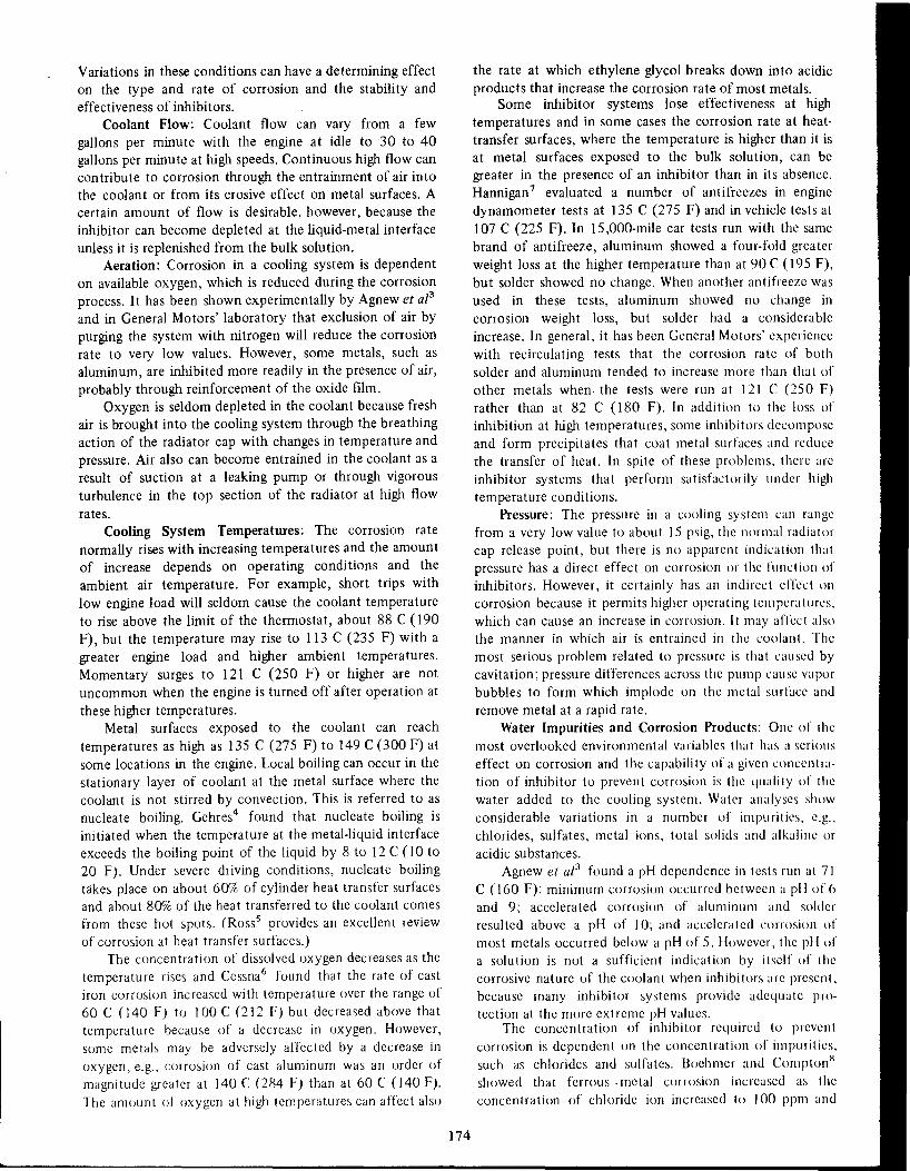
Variations in these conditions can have a determining effecton the type and rate of corrosion and the stability andeffectiveness of inhibitors.
Coolant Flow: Coolant flow can vary from a few
gallons per minute with the engine at idle to 30 to 40gallons per minute at high speeds. Continuous high flow cancontribute to corrosion through the entrainment of air intothe coolant or from its erosive effect on metal surfaces. Acertain amount of flow is desirable, however, because the
inhibitor can become depleted at the liquid-metal interfaceunless it is replenished from the bulk solution.
Aeration: Corrosion in a cooling system is dependenton available oxygen, which is reduced during the corrosion
process. It has been shown experimentally by Agnew et aZ3
and in General Motors' laboratory that exclusion of air by
purging the system with nitrogen will reduce the corrosionrate to very low values. However, some metals, such asaluminum, are inhibited more readily in the presence of air,probably through reinforcement of the oxide film.
Oxygen is seldom depleted in the coolant because freshair is brought into the cooling system through the breathingaction of the radiator cap with changes in temperature andpressure. Air also can become entrained in the coolant as aresult of suction at a leaking pump or through vigorousturbulence in the top section of the radiator at high flowrates.
Cooling System Temperatures: The corrosion ratenormally rises with increasing temperatures and the amountof increase depends on operating conditions and theambient air temperature. For example, short trips withlow engine load will seldom cause the coolant temperatureto rise above the limit of the thermostat, about 88 C (190
F), but the temperature may rise to 113 C (235 F) with agreater engine load and higher ambient temperatures.Momentary surges to 121 C (250 F) or higher are notuncommon when the engine is turned off after operation at
these higher temperatures.Metal surfaces exposed to the coolant can reach
temperatures as high as 135 C (275 F) to 149 C (300 F) atsome locations in the engine. Local boiling can occur in thestationary layer of coolant at the metal surface where thecoolant is not stirred by convection. This is referred to asnucleate boiling. Gehres4 found that nucleate boiling isinitiated when the temperature at the metal-liquid interfaceexceeds the boiling point of the liquid by 8 to 12 C (IO to20 F). Under severe driving conditions, nucleate boilingtakes place on about 60% of cylinder heat transfer surfacesand about 80% of the heat transferred to the coolant comes
from these hot spots. (Rosss provides an excellent reviewof corrosion at heat transfer surfaces.)
The concentration of dissolved oxygen decreases as the
temperature rises and Cessna6 found that the rate of castiron corrosion increased with temperature over the range of60 C (] 40 F) to ] 00 C (2] 2 F) but decreased above thattemperature because of a decrease in oxygen. However,some metals may be adversely affected by a decrease in
oxygen, e.g., corrosion of cast aluminum was an order ofmagnitude greater at ]40 C (284 F) than at 60 C (]40 F).The amount of oxygen at high temperatures can affect also
174
the rate at which ethylene glycol breaks down into acidicproducts that increase the corrosion rate of most metals.
Some inhibitor systems lose effectiveness at high
temperatures and in some cases the corrosion rate at heattransfer surfaces, where the temperature is higher than it isat metal surfaces exposed to the bulk solution, can begreater in the presence of an inhibitor than in its absence.Hannigan 7 evaluated a number of anti freezes in enginedynamometer tests at 135 C (275 F) and in vehicle tests at107 C (225 F). In 15,000-mile car tests run with the samebrand of antifreeze, aluminum showed a four-fold greater
weight loss at the higher temperature than at 90 C (195 F),but solder showed no change. When another antifreeze wasused in these tests, aluminum showed no change in
corrosion weight loss, but solder had a considerableincrease. In general, it has been General Motors' experiencewith recirculating tests that the corrosion rate of bothsolder and aluminum tended to increase more than that of
other metals when. the tests were run at ] 2] C (250 F)rather than at 82 C (180 F). In addition to the loss ofinhibition at high temperatures, some inhibitors decomposeand form precipitates that coat metal surfaces and reducethe transfer of heat. In spite of these problems, there arcinhibitor systems that perform satisfactorily under hightemperature conditions.
Pressure: The pressure in a cooling system can rangefrom a very low value to about 15 psig, the normal radiatorcap release point, but there is no apparent indication thatpressure has a direct effect on corrosion or the funct ion ofinhibitors. However, it certainly has an indirect effect oncorrosion because it permits higher operating temperatures,which can cause an increase in corrosion. It may affect alsothe manner in which air is entrained in the coolant. The
most serious problem related to pressure is that caused bycavitation; pressure differences across the pump cause vaporbubbles to form which implode on the metal surface andremove metal at a rapid rate.
Water Impurities and Corrosion Products: Onc of themost overlooked environmental variables that has a serious
effect on corrosion and the capability of a given concentration of inhibitor to prevent corrosion is the quality of thewater added to the cooling system. Water analyses showconsiderable variations in a number of impurities, e.g.,chlorides, sulfates, metal ions, total solids and alkaline oracidic substances.
Agnew et aZ3 found a pH dependence in tests run at 71C (I 60 F): minimum corrosion occurred between a pH of 6and 9; accelerated corrosion of aluminum and solder
resulted above a pH of ]0; and accelerated corrosion ofmost metals occurred below a pH of 5. However, the pH ofa solution is not a sufficient indication by itself of thecorrosive nature of the coolant when inhibitors arc present,because many inhibitor systems provide adequate protection at the more extreme pH values.
The concentration of inhibitor required to prevent
corrosion is dependent on the concentration of impurities,such as chlorides and sulfates. Boehmer and ComptonR
showed that ferrous. metal corrosion increased as the
concentration of chloride ion increased to ]00 ppm and

that of the sulfate ion to 300 ppm. Aluminum corrosionincreased also with an increase in chloride ion concentra
tion. Dempster9 has shown aluminurn to be sensitive totrace amounts of copper (0.3 to 2 ppm) in glycol-watersolutions, with an increased effect when 10 to 15 ppm ofchloride ion was present.
Rowe and Walker' 0 used the change in electricalconductance of thin metal strips to study the effects ofwater impurities on the corrosion of steel and aluminum.The corrosion of steel at 26 C (79 F) was affected to thesame degree by equal concentrations of either chloride orsulfate ion or combinations of the two. The increase in
corrosion was rapid up to a concentration of 50 ppm,followed by a slower rise between 50 and 300 ppm.
Bicarbonate and carbonate ions had a lesser effect on
steel corrosion at a concentration of 50 ppm, but thecorrosion at 100 ppm approached that produced bychloride and sulfate ions at the same concentration.
Corrosion of aluminum was investigated at two temperatures. At 26 C, neither chloride, bicarbonate, or copperions alone or a combination of any two caused an increasein aluminum corrosion, but a combination of all three
produced a synergistic effect that increased pitting corrosion. The size of the pits decreased and the pit densityincreased with an increase in bicarbonate ion concentration.
At 71 C, pitting occurred only when copper and cWorideions were present in combination; the addition of bicarbonate ion stopped the pitting and inhibited generalcorrosion at low concentrations of bicarbonate. Further
investigations of this effect on pitting showed a dependenceon temperature and on bicarbonate ion concentration.
Prccipitates from the water and corrosion productsfrom the metal accelerate the inhibitor depletion rate byproviding large surface areas for inhibitor adsorption. Greenet ai" found a hundredfold increase in the corrosion of
iron in the presence of hydrated iron oxide and a lesserincrease in the corrosion of aluminum and solder. Mercer
and Wormwell' 2 reported that suspensions of ferrichydroxide caused a rapid depletion of phosphate inhibitorbut had a lesser effect on benzoate and no effect on borate.
Some corrosion products accelerate the breakdown of
ethylene glycol into acidic compounds. For example,corrosion products of copper have been found to have acatalytic effect on the thermal degradation and oxidation
of glycol.' 3 Although acids formed may be present atconcentrations as low as 0.1 %, they affect the stability ofprotective films and make the inhibition of corrosion more
difficult. The acids have been identified by Mercer andWormwell'2 as being about 80% formic and the remainderglycolic.
Metals, Galvanic Couples, and Crevices: The coolingsystem is made up of a variety of metals and polymericmaterials. The radiator and heater core, which have the
largest area of material exposed to the coolant, are usuallyconstructed of brass or combinations of brass and copperthat are bonded together with lead-tin solders. High-leadsolders with a small addition of silver are used to bondheaders to tubes and tanks. Brazed aluminum radiators have
also been used to some extent. The next largest area of
175
metal is found in the block and head, which are usuallymade of cast iron. Aluminum or combinations of aluminum
and cast iron have also been used for these parts. Thepump, timing chain cover and thermostat housing are madeof cast iron or aluminum. The pump impeller is usuallymade of cast iron, steel or a polymeric material. Lesseramounts of metals are found in brass thermostats, zinc
coated steel core plugs, steel or aluminum radiator caps,steel gaskets and brass or steel temperature sensing devices.
Surface roughness, shape, stress and heat treatment ofmetals affect corrosion and the effectiveness of inhibitors.
Many galvanic couples of metals are found in an engine andits associated parts and these couples increase the difficultyof inhibiting corrosion.
Crevices and low coolant-flow areas are difficult to
avoid in the design of an engine system. Such areas arefound at hose connections, gaskets, core plugs, internalpassage ways in the block and head and parts of theradiator. These areas are difficult to protect becauseinhibitors become depleted and are not readily replenished.
Operating Conditions and Maintenance of the System:
The manner in which a vehicle is operated and the coolingsystem is maintained may have a determining effect oninhibition. Periodic inspection of the cooling system isimportant if difficulties are to be avoided. Importantfactors to consider are coolant temperature (overheating orovercooling), coolant level and coolant condition.' 4 Cool
ant may be lost by overflow as the result of overfIlling andsubsequent thermal expansion or by foaming and boiling. Ifwater alone is added rather than a solution of water and
antifreeze to make up the loss, the inhibitor systembecomes diluted.
Properly maintained cooling systems do not have to be
cleaned when changing the antifreeze; flushing with watershould be sufficient. If the system becomes badly corroded,then a heavy duty cleaner, such as oxalic acid, can be used.This treatment should be followed with neutralization of
residual acid with bicarbonate solution. Unfortunately,because it is practically impossible to flush out all of the
oxalates, they tend to increase the tendency for corrosionto occur even with proper inhibition. Therefore, thisprocedure should be used with caution. In some cases.tubes may have to be cleaned by forcing rods through themto remove deposits causing plugging.
If a head gasket is not sufficiently tigllt, exhaust gascan leak into a cooling system. Because these gases fonnacids, inhibitors and other alkaline substances are neutralized and the corrosion rate tends to increase. This is adifficult condition to overcome with inhibitors. the most
practical solution is to tighten the head gasket.
Operating conditions affect the life of inhibitors in
antifreeze solutions and the corrosion susceptibility ofmetals in the system. For example. operating under heavyload will increase the temperature. or operating with aleaking pump will allow more air to enter the systcm. Insummary. the life expectancy of inhibited antifreezc

solutions is shortened by the following service conditions.15
1. High mileage2. High speed and heavy load3. Air suction at leaking pump4. Exhaust gas leakage5. Rust deposits6. Hot spots7. Contamination
Test Methods for the Evaluation of Inhibitor SystemsA number of conventional electrochemical techniques
has been used to determine the effectiveness of inhibitors
for engine coolants. They include the measurement ofpotentials, the determination of the rate of potential decayand the study of anodic and cathodic behavior of metals.Each of these methods has contributed meaningful information to an understanding of corrosion phenomena and thefunction of various inhibitors. It was only natural that asnew techniques were developed they would be applied tothe study of engine coolants. Walker and France16 haveused the linear polarization method to determine instantaneous corrosion rates in situ in an automotive cooling
system. Corrosion rates of test specimens and the degree ofinhibition provided by the coolant have been determinedunder various operating conditions in the cooling system ofan operating vehicle. Indeed, the corrosion rate of actualparts that were electrically isolated was determined. Thismethod permits one to follow transients with changes inconditions, such as temperature, inhibitor content, coolantflow and aeration. However, the determination of metal
specimen weight losses or visual observation of parts forcorrosion are still the most popular means for evaluatingcorrosion in most tests.
A number of standard test methods for the evaluation
of engine coolants has been reviewed by Rowe.1 7 Tests aredivided into four categories:
I. Laboratory glassware tests2. Simulated service tests
3. Engine dynamometer and no-load engine tests4. Field service tests
Each test in the sequence becomes more discriminatingthan the previous test because more engine components areused and service operating conditions are simulated moreclosely.
Laboratory Glassware Test: The ASTM Standard TestMethod 0 138418 is typical of this simple method in whicha beaker is used as the test vessel. A bundle of six different
metals, divided into two sets of three metals in galvaniccontact, is immersed in a 750-ml volume of solution, which
is prepared from one part antifreeze and two parts corrosivewater (J 00 ppm each of chloride, sulfate and bicarbonateions added as the sodium salts). The solution is aeratedcontinuously and maintained at a temperature of 88 C.Because of the simplicity of the method, a number of testscan be run at one time. However, the results must beviewed with some reserve because the test simulates only afew service conditions. The test is a screening procedure
176
that indicates the most promising inhibitors so they can beevaluated further by more selective methods.
Simulated Service Test: More objective results can beobtained by incorporating actual automotive componentsinto the test equipment and by simulating service conditions to a greater degree. This is the goal of the standardASTM Method 0 2570.19 A radiator, pump and timingchain cover, thermostat housing and hoses are the automotive components used in this test. A cast iron oraluminum pot is used to simulate the large surface area ofthe coolant passages in the engine. These components aremounted on a test stand and joined together with hoses toform a recirculating system. Fifteen liters of a solution ofone part antifreeze and two parts corrosive water iscirculated continuously at a flow rate of 30 to 35 gpm anda temperature of 88 C for 1000 hours (equivalent to about60,000 miles of service). Three sets of specimen bundles areimmersed in the solution in the pot during the test todetermine inhibitor efficiency by weight loss. The effectiveness of inhibitors over the entire test period can bedetermined by the use of additional sets of specimens thatare removed at periodic intervals.
Inhibitor systems are stressed more severely by thistype of test than by the glassware method, but they seldomshow the degree of depletion found during automotive usedue to reaction in the system or through depletion.2oHowever, inhibitor depletion can be simulated by removinga portion of the antifreeze solution at weekly intervals andreplacing it with an equivalent amount of corrosivewater. I 7 This procedure has the advantage of allowing aprotective film to form at a high inhibitor concentrationbefore the dilution occurs, which is the manner that itoccurs in service. A low concentration of inhibitor will
continue to protect metals under these conditions; whereas,it would not if the test was initiated at the low inhibitorconcentration.
Engine Dynamometer and No-Load Engine Test: A testthat uses an operating engine can be expected to reproduceservice conditions more closely than other tests. This is theobjective of the engine dynamometer test proceduredescribed in ASTM Standard Method 0 2758.21 This test is
usually run with a standard engine at simulated 60 mphroad-load conditions for 600 or more hours. The engine isinstrumented to show changes in parameters of interest.Corrosion can be determined from test specimens that areinstalled in the radiator hose or the heater by-pass circuitand by the inspection of parts. The change in theeffectiveness of inhibitors, due to gradual depletion withtime, can be shown by removing specimens at periodicintervals and replacing them with new specimens anddetermining the corrosion rate over each interval of time.The engine dynamometer test stresses coolants and inhibitors more like cars in service because the operating engineprovides greater heat flux at metal surfaces, a factor whichhas a great effect on inhibitor depletion.22
Because of the cost involved in engine dynamometertests, no-load engine tests have been used as an alternative.
An engine can be located at any convenient place and

operated for hours with little attention. The heat flux inthis test is less than that in the dynamometer test becausethe engine is run without load; thus, it has a less severeeffect on inhibitors.
Field Service Test: The culmination of all test programsis the evaluation of inhibitor systems under vehicle
operating conditions. Because corrosion tends to be greaterat higher coolant temperatures, mileage becomes an important parameter. Taxi cabs, police cars, fleet cars and provingground cars provide a convenient source of vehicles thatwill accumulate mileage rapidly. ASTM RecommendedPractice D 284723 gives detailed instructions for performing such a test. Two sets of metal specimens are installed ineither the upper radiator hose or the partial-flow heatercircuit. One set of specimens can be removed at intervals toindicate inhibitor depletion. The test is run for 25,000miles and a sufficient number of vehicles, usually no lessthan five, is used to obtain a representative sample.Limitations are cost, the time involved in running a test andthe difficulty in maintaining direct supervision over thetest.
Special Tests: Conditions associated with some specifictypes of corrosion usually are not reproduced in generaltest procedures, so it is often necessary to develop specialtests. For example, the service conditions that producecavitation-erosion of aluminum pumps and timing chaincovers are not duplicated in most of the tests previouslydiscussed. Although field tests can be run in police cars,where cavitation tends to be severe because of rapidacceleration and high-speed driving, they are time consuming. The obvious need for a short test to evaluateinhibitors led to the development of ASTM StandardMethod D 2809.24 A standard automotive pump is testedat a coolant temperature of 113 C in a recirculating systemat a pressure of 15 psig. The pump is operated at 4600 rpmand the pressure differential acrOss the pump can beadjusted to give a cavitating condition. The pump isremoved and inspected for cavitation damage after 100hours of operation.
It is not always necessary to develop new tests ifstandard test procedures can be modified to emphasizesome specific condition. For example, the SimulatedService Test has been used to evaluate coolants at operatingtemperatures as high as 121 C; other tests have beenmodified to emphasize cyclic pressures, coolant impingement, or crevice corrosion. When a particular condition isstressed in any test, the results must be interpretedcarefully because the condition may be overemphasized inan effort to accelerate the test.
Inhibitors
Although it is an accepted practice now to use aninhibited antifreeze in the cooling system all year around,the practice in previous years was to use inhibited antifreeze in the winter and water plus inhibitors in thesummer. Although this latter procedure had recognizedvalue from a maintenance viewpoint, it fell into disreputebecause automobile owners often neglected to add inhibitors in the summer. Furthermore, commercial summer
177
inhibitors, which were often only emulsifiable oil, failed toprovide the total protection obtained from most formulated antifreeze products.
A natural step was to recommend the use andmaintenance of inhibited antifreeze for both winter and
summer. This course was taken by most major automobilemanufacturers, who also recommend that the antifreezeconcentration be maintained at a minimum of 44%. Eventhe aftermarket antifreeze products are sold with therecommendation that they be used both in winter andsummer. After one or two years of use, depending on milesdriven, the system should be drained, flushed and filledwith a new antifreeze solution.
Because operating temperatures have increased inrecent years and because there is a greater need for ahigh-boiling-point material, ethylene glycol antifreeze isused almost exclusively throughout the industry in theUnited States. The Chemical Specialities ManufacturersAssociation (CSMA)2S reported that 163 million gallons(99.5% of the market) of ethylene glycol antifreeze wassold in 1969, as compared to 742 thousand gallons ofmethyl alcohol antifreeze. Because of the trend to the
greater use of ethylene glycol, it was only natural that theemphasis of inhibitor research be directed to glycolcoolants. It should not be inferred from this statement that
other media have not been used in the development ofinhibitor systems for engine coolants; many studies havebeen made with water alone or with other antifreezecoolants.
Methoxy propanol, a glycol ether, was introducedrecently as a substitute for ethylene glycol? 6 but its use sofar has been restricted to heavy duty vehicles. Its principaladvantage is reported to be better compatibility with engineoil than ethylene glycol in the event of a coolant leak. It
has a lower boiling point than glycol but reportedlyequivalent heat transfer characteristics. Inhibitors commonly used in glycol antifreeze are not ordinarily soluble inconcentrated methoxy propanol; therefore, a new inhibitorsystem was developed that presumably provides protectioncomparable to that of a good quality glycol antifreeze. Thisantifreeze product has been used very little in automotivecooling systems because of cost and general satisfactionwith glycol products.
For a complete review of specific inhibitor formulations for engine coolants, the reader is referred to thepatent literature and published papers.2 7 ,28 The intent inthis review will be to discuss published results associatedwith the evaluation of inhibitors.
Althougl1 many chemicals have been investigated fortheir inhibitive properties in engine coolants, only a fewdifferent chemicals are actually used in the large number ofproducts on the market today. Many of the inhibitors inantifreeze products and in cooling system antirust additivesare referred to by Beynon29 in his discussion of proceduresfor the qualitative and quantitative determination ofinhibitors. Some of the commonly used chemicals arenitrites, nitrates, phosphates, borates, silicates, arsenites,
chromates, amines, benzoates, mercaptans, organic phosphates and polar or emulsifiable oils. Chemicals that have
'",,
been used to a lesser extent are carbonates, molybdates,
tungstates, arsenates, aluminates, oxides, citrates, cinnamates, selenites, salycilates and carbamates.
Thomas and Nurse30 studied the anodic passivation ofiron in deaerated solutions of inhibitive ions at O.IM
concentrations and found the effect of anions on passivation to be related to the tendency for the anion to preserveor to break down oxide films. Based on the determination
of critical current densities, the difficulty of producing apassivation condition for a number of anions increased inthe order nitrite < hydroxide < chromate < borate <hydrogen phosphate < carbonate < benzoate < bicarbonate< nitrate. Brasher31 found that the difference between
aggressive action and passivation is associated with theconcentration of the anion. Some anions tend to be
aggressive at very low concentrations and inhibitive athigher concentrations. Moreover, some anions are moreaggressive to one metal than another and considerationmust be given to the properties of the anion in relation tothe oxide or metallic ion of concern. The rating of inhibitorefficiencies showed a few variations in the position ofinhibitors from that of Thomas and Nurse30 but manysimilarities. The order of decreasing inhibitor efficiencieswas found by Brasher31 to be nitrite > chromate benzoate > phosphate > hydroxide - carbonate > bicarbonate> nitrate.
Levy32 investigated the anodic and cathodic behaviorof steel in inhibited 30% ethylene glycol-water solutions byapplying an external electromotive force to a copper-steelcouple. He found that borate, nitrite, chromate, silicate,benzoate and triethanolamine functioned as anodic polarizers;whereas, mercaptobenzothiazole was a cathodic polarizer. Northan and Boies33 tested 68 different chemicals for
effective inhibition of aluminum by measuring the volumeof hydrogen released by the corrosion reaction. It wasconcluded that effective inhibitors were those that pre
vented a pH rise, formed insoluble aluminum compounds,or formed adsorbed films because of their semi-polarcharacteristics. Cessna34 emphasized the significance ofsurface conditions and he found that precorroded steel wasmore difficult to inhibit again~t further corrosion than a
clean, polished metal surface. Using a change in metalconductivity to shbw inhibitor effectiveness in glycol-watersolutions containing cWoride, suifate and bicarbonate salts,
he f~und that borax at a concentration of 0.18% by weightwas the least effective inhibitor orseveral for the protection
of steel. Bop!,x, IIletasilicate and polar oil protectedalumirium,'but benzoate and nitrite did not. Borax, nitrite,
and polar ,p\I were ~ffecti.ve inhibitors for copper and brasscorrosion .... I . '.
Rowe35 . con~ucted a series of evaluation tests on anumber oC metali using 1% solutions of sodium borate,
sodium ben~of~e'~' ~Qqi~m nitrite, potassium dichromate,emulsifiable oil and the sodium salt of mercaptobenzothiazole (MBT). Each test.was run on a single metal at 77 C
(170 F) for 14 days. ~9I,lftioris were either tap water or a50% solution of glycol-tllp: water 1 wi~h chloride and sulfatesalts added in some cases to' Increase corrosivity. All
inhibitors were fairly effective in the absence of the
178
cWoride and sulfate, but in their presence borate, benzoateand MBT were less effective and caused some pitting ofaluminum. Nitrite, dichromate and emulsifiable oil gave thebest overall protection, but dichromate showed incompatibility with glycol in these tests.
Static corrosion tests of various metal couples were runfor 10 months at room temperature. Borate, benzoate andMBT provided satisfactory protection for copper, solderand brass; nitrite for steel, cast iron, copper and brass;dichromate and emulsifiable oil for all metals exceptaluminum; and MBT for copper and brass.
When results from all test conditions were taken into
consideration, nitrite provided the best protection forferrous materials, MBT for brass and copper, and dichromate and emulsifiable oil general protection for mostmetals. On the basis of this information, a combination ofemulsifiable oil, sodium nitrite and MBT was tried in asimulated engine cooling system test and was found toprovide excellent protection for six weeks at 82 C (180 F).
Chromate Inhibitorsfor Cooling System
It is apparent that a single chemical seldom providescomplete protection to an engine cooling system because ofthe varied service conditions that can be encountered, but it
has taken many years of testing to reach this conclusion.Chromate was one of the earliest inhibitors suggested foruse in engine cooling systems. Darrin36,3 7 discussed its usein diesel engine cooling systems or in automotive coolingsystems during the summer months when water alone wasused. Nitrates, borates and carbonates have been used in
combination with chromates to provide added protectionand better pH control.
Best and Roche38 found satisfactory protection infield tests with the use of chromates in methanol antifreeze.
However, they cautioned that hexavalent chromium issusceptible to reduction to trivalent chromium (whichforms insoluble Cr203) by substances in the solution andby light. Rowe39 studied the use of sodium chromate withethylene glycol in considerable detail. Qualitative testsshowed that the reaction between chromate and ethyleneglycol is dependent upon temperature, pH and thecatalyzing effect of light. Degradation began within a fewhours in the presence of light but only slight breakdownoccurred in a four-month storage period in the absence oflight.
Car tests were run with 2000 ppm chromate inethylene glycol solutions, but when chromate was addedonce only, it was soon depleted. When chromate was addedcontinuously by means of a by-pass filter, a concentra tionof 450 ppm was maintained. 1t was concluded that undercertain conditions and with the exclusion of light,chromates could be used with ethylene glycol solutions.However, they are used infrequently in automotive engine cooling systems today to avoid the possible formation of insoluble chromium oxide. Chromates are still used
in commercial by-pass filters for heavy-duty vehicles andeven somewhat successfully with ethylene glycol coolants.Some antifreeze products are more compatible than others

with chromates and the antifreezes to be used are selectedon the basis of compatibility tests.
Advantages of By-Pass FilterThe concept of adding an inhibitor to the cooling sys
tem by the use of a by-pass filter has some merit for vehiclesthat are on a maintenance schedule because filters are easilyreplaced, which ensures an appropriate level of inhibitor.However, if a well-inhibited antifreeze is used, maintainedand replaced at proper intervals, .there is little need for thisapproach. Because of the inherent vulnerability ofchromate to reduction in organic fluids and because of thedifficulties that can arise if large amounts of precipitates areformed, it appears reasonable to exclude chromates fromthe system. In recent years, other inhibitors, such as boratesand nitrites, have been used in by-pass filters and thisapproach would appear to be safer.
Chromates may still be used successfully in watersystems, such as diesel engine cooling systems and optimumefficiency under recirculating and cavitating conditions canbe obtained at a concentration of 500 ppm.40-42 Theconsumption of chromate is high during the first few daysbut stabilizes within three months. Chloride ions canaccelerate consumption so an increased concentration ofchromate is required in the presence of chloride.
,Borate InhibitorsA good share of the inhibitor formulations in the
United States contain. borate. Several of these formulasfrom the patent literature have been listed by Jackson etal.28 Borates are used as either the tetraborate (borax) orthe metaborate. Because of their solubility in ethyleneglycol, they are ideal for formulating antifreeze products.However, borates alone seldom provide adequate metalprotection in the variety of waters that are used in enginecooling systems.43
Dulat44 stated that while borax preserves the protective oxide film on iron, it does not become part of the film.A concentration above 0.6% is required for protection. Italso protects copper and is satisfactory for aluminum butnot when aluminum is coupled to iron or copper. Dulat4Sran a five-year service test on a borax-based antifreeze withan inhibitor concentration in the glycol of 3.3 borax, 0.11MBT, 0.11 Na2Si03 . 5H20 and 0.04 Ca(OH)2 in percentby weight. He reported excellent corrosion inhibition withabout a 33% glycol solution. No depletion of boraxoccurred in 6 months, but over 50%of the MBTand silicatewas depleted. These results should be viewed with somecaution, because only one test car was used and becausetotal accumulated mileage in five years was only 48,000,which is considered light-duty operation. Furthermore, thecoolant was replaced at six-month intervals and a relativelymild water containing 20 ppm chloride ion was used fordilution of the glycol. As mentioned previously, bothCessna34 and Rowe3s found reduced effectiveness ofborax with increases in chloride or sulfate ion concentrations.
Weibu1l43 found that borax alone did not providesatisfactory protection in car tests. Less corrosion of
179
aluminum was reported by Collins and Glover46 in boraxinhibited water than in borax-inhibited glycol solutions,presumably because of the formation of acid products inthe glycol solutions. Bregman and Boies47 in their investigation found borate-nitrite to be an effective combination.
Although borates have definite inhibitive qualitiesunder certain environmental conditions and reinforce theeffect of other inhibitors, one of their principal functions isto provide reserve alkalinity and buffering action againstacids. Reserve alkalinity is a term that is used to define thecapability of a solution to neutralize acids. It is given anumerical value in terms of tl1enumber of milliliters ofO.IN HCl required to titrate 10 ml of concentratedantifreeze to a pH of 5.s.4 8
Inhibitors for Copper AlloyMercaptobenzothiazole (MBT) and benzotriazole49
(more recently tolyltriazole has been proposed as analternative) are two inhibitors that have contributed muchto the success of formulated antifreezes because of theirspecific inhibition of copper and its alloys. By preventingthe corrosion of copper, these inhibitors have the addedeffect of reducing the corrosion of iron and aluminum sincefewer copper ions are available to migrate to those metalsurfaces to deposit and cause galvanic effects. MBT issubject to degradation from heat and light and sodiumsulfite is added to the commercial product (a water solutionof the sodium salt of MBT) to prevent its oxidation tobenzothiazyl disulfide. Because of this instability, antifreeze with MBT as an inhibitor should be'stored in the
dark or in opaque containers. MBT is also pH dependentand it is necessary to maintain the ,pH on the alkaline side.SquiresS0 claims that copper corrosion products in thesystem consume MBT. The lowest effective concentrationwas found to be about 0.01%. At an initial concentration of0.1%, it took 8 to 16 months in car tests to reach the low'level of 0.01%.
Benzotriazole is reported to be more stable than MBTto light and to high coolant temperatures and to provideequivalent inhibition at lower concentrations. There is lessinformation in the literature on its evaluation than on MBT,but it is known to be used in a number of formulations.
Emulsif13ble Oils
Emulsifiable oils ("soluble oils") are another categoryof corrosion inhibitors that have been used in the automotive engine cooling systems. They consist of a combination of a mineral oil base and one or more polar organicmaterials, such as fatty acids or their salts, petroleumsulfonates, or sulfated vegetable oils, along with emulsifyingagents. Evanss1 says that the oil particles carry a negativecharge and are deposited at the anodic points in thecorrosion process. Powers and Cessnas2 say that polar oilmolecules are adsorbed onto metal surfaces and provide athin layer of the carrier oil. It was claimed on the basis ofchange in potential that the higher absorption of oxygen bythe oil film leads to passivation of the metal surface andthat the barrier action of the oil allows passivity to be
'I

maintained under unfavorable conditions. Neither the oilbase nor the additive was effective alone.
Emulsifiable oils are not added normally to antifreezeconcentrates, although a polar type of oil was used formany years in one major antifreeze product. The use of emulsifiableoil has been restricted to additions to water coolantsduring the summer months and for many years a fewounces of emulsifiable oil was added to production-carcooling systems as a pump lubricant. Sealers that are addedto cooling systems to reduce leakage contain oil in somecases.
There are some disadvantages to the use of emulsifiableoils. They will contribute to the growth and stability offoam if there is a condition in the cooling system thatencourages its formation. If the emulsion breaks, theseparated oil floats on the surface of the coolant and coatsmetal surfaces, affecting the transfer of heat from the metalto the coolant. Oil can cause degradation of some polymeric materials used for hoses. Finally, there are variationsin the inhibitive qualities of emulsifiable oils, even in thesame brand, because of variations in composition ordifferences in manufacturing processes.
Mixed Inhibitor SystemsOne of the inhibitor formulations that has received
considerable attention, particularly by the British, is thebenzoate-nitrite combination. Mercer and Wormwell12,53,54 reported their findings with this formulationin a number of publications in the literature. Five percentsodium benzoate and 0.3% sodium nitrite in a 25% ethyleneglycol solution protected cast iron and solder as well asother metals at room temperature for five years. The nitriteconcentration can be reduced to 0.1% under conditions ofintermittent heating. Sodium benzoate alone is less effective for cast iron than steel. Sodium nitrite alone is veryeffective for ferrous metals but attacks solder. The combination of the two prevents corrosion of cast iron, solder,brass and copper in 20% glycol solution with intermittentheating.
In low mileage (2500 miles) car tests, 1.5% benzoatedid not prevent corrosion of cast iron in new engines butarrested corrosion in used engines; whereas, 1.5%benzoateand 0.1% nitrite were effective in both cases. Corrosion ofaluminum was not completely pre~ented in either case. ThepH was found to rise as high as 10.0 and the concentrationof inhibitors dropped. Based on recirculating tests run at 80C (176 F) for a minimum of 1000 hours, Collins andGlover55 found that a 20% glycol solution containing 1.2%benzoate and 0.1%nitrite showed a steady decline in nitriteover the first 800 hours while the benzoate remainedconstant. In water alone, the benzoate showed some declineafter 500 hours.
In a simulated aluminum-alloy-engine test, the nitriteconcentration dropped to zero in 1000 hours,56 and thesolution became corrosive to aluminum as the inhibitor
depleted and oxidation products were formed. Aluminumalloys were pitted under conditions of low coolant flow.Weibu1l43found the benzoate-nitrite combination to be themost stable of four antifreeze formulations tested. Collins
180
and Glover57 suggested that this combination of inhibitormay damage rubber and benzoate-nitrite-borax may causesolder corrosion. Benzoate in another test was found tocreep and cause etching of aluminum above the liquidlevel.9
Another formulation that has been evaluated extensivelyby the British is one containing 0.4% triethanolamine(TEA), 0.19% phosphoric acid and 0.041% of the sodiumsalt of MBT. Triethanolamine phosphate (TEP) when usedwithout MBT in glycol-water solutions causes acceleratedcorrosion of copper alloys by complexing the coppercations, allowing them to migrate through the solution anddeposit on aluminum or steel.58 Squires50 found that TEPdoes not prevent the oxidation of glycol to form acids, butit does provide a weak buffering action that might be morepreferable than the effect of more alkaline buffers that canattack some metals. In a simulated service test, the acidicoxidation products rose from 0 to 0.3 gram equivalents perliter, with most of the products being formic acid.56 TEPhas some softening effect on hard waters, but the quantityof insoluble phosphates that are formed has little effect onthe function of the cooling system. Weibu1l43reported thatTEP-MBT formulated antifreeze gave good protection in acar test until the inhibitors were depleted. Collins andHigginsl3 ran car tests with this formula and found thatmost of the phosphate and MBT werelost in two months or4000 miles and they associated the increased corrosion tothe formation of acids from glycol breakdown. Collins andGlover55 ran simulated service tests at 80 C, using a 20%glycol solution and the TEP-MBT inhibitor system. Amarked decrease in the concentration of MBT (0.035 to0.005%) occurred in the first 100 hours, followed by a slowdecline to almost zero in 900 hours. There was a steadydecline in phosphoric acid and TEA content over a600-hour period and at this point the phosphoric acidcontent was almost zero and the copper in solution rosefrom 40 to 150 ppm. A drop in pH and a rise in acidicproducts caused increased corrosion of aluminum, cast .ironand bronze. In water alone, adequate protection wasmaintained even though the MBTwas partially depleted.
There has been a definite trend in recent years in theUnited States to include phosphate in inhibitor formulations. Phosphate has buffering action and increases thereserve alkalinity. Furthermore, it has been found to bevery effective in reducing cavitation of aluminum pumps.The antifreeze for military use in the United States formany years is identified as Type I antifreeze and it contains2.5% borax in the concentrate.59 In order to improve theinhibitive quality of the coolant, it is recommended nowthat other inhibitors be added to the cooling system from aseparate packaged product. A 170 g (6 oz) package containsapproximately 26 g of mercaptobenzothiazole, 65 g ofanhydrous Na2B407, and 16 g of anhydrous Na2HP04.6oThe inhibitor is added to either water or a Type Iantifreeze-water system at a concentration of 28 g (1 oz)inhibitor to 1.9 g (2 qts) of water. Conley,61 who reportedon the development and evaluation of this inhibitor system,found satisfactory corrosion protection in both hard andcorrosive water in vehicle tests which accumulated 34,000

miles over a 13-month period. (A new Military Specification, MIL-A-46153(MR), dated October 19, 1970, coversan antifreeze compound that includes all of these inhibitorsin a single package.)
New Formulation Developed
A formulated antifreeze product was developedrecently by the General Motors Corporation.6Z Thisproduct contains the following concentration of inhibitorsby weight percent in the antifreeze concentrate: 0.21NaN03; 0.98 Naz B407 . 5Hz 0; 0.17 Naz Si03 . 5Hz 0;0.43 Na3 P04 . 12Hz 0; 0.55 ofa 50% water solution of thesodium salt of MBT and 0.19 NaOH. This combination of
inhibitors was selected after evaluating a large number ofcandidate formulas. Each chemical serves a particularpurpose:
1. Nitrate for protection of aluminum and solder,2. Borate for its buffering action, reserve alkalinity and
protection of ferrous metals,3. Silicate for general protection of all metals,4. Phosphate for protection of ferrous metals and
aluminum and its buffering action,5. MBT for protection of copper and brass.6. NaOH for additional reserve alkalinity.
Furthermore, silicate and phosphate are effective againstcavitation.
This type of formulated antifreeze provided excellentcorrosion protection at a 44% concentration, using corrosive water for dilution in 10 test cars for a two-year period,with an accumulated mileage in each car of 20 to 25,000miles. Normal depletion of silicate, MBT and phosphateoccurred, but the pH and reserve alkalinity of the coolantsolutions showed only a nominal change in two years. Theproduct has reasonably good storage stability, goodcompatibility with other antifreezes, good high temperaturestability and good protection against cavitation.
Cavitation ofAluminumCavitation-erosion generally has not been a major
problem in the au tomotive engine cooling system. However,there has been considerable research associated with the
cavitation of aluminum pumps and timing chain covers.Because of the advantages in being able to use die castaluminum components rather than cast iron, there was atrend in this direction until tests and service experienceindicated the susceptibility of this material to cavitationdamage under some operating conditions. Under severecavitating conditions, the metal can be perforated, leadingto loss of coolant or entry of the coolant into the oilsystem.
The subject of cavitation has had extensive coverage inthe literature, and a general review has been given byGodfrey.63 Much of the information has been related tocavitation of diesel cylinder liners rather than that ofautomotive components. Because cavitation damage resultsfrom the formation of vapor bubbles under differentialpressure conditions and the subsequent implosion of thesebubbles on the metal surface, the physical properties of the
181
liquid and the condition of the metal surface have adetermining effect on the severity of the cavitation.Inhibitors in coolants can either reduce or increase cavita
tion, depending on their effect upon the physical characteristics of the coolant and the formation of vapor bubblesand their effect upon the characteristics of the metalsurface. In the latter case, the inhibitors must have goodstability at the metal surface.
Wilson64 gives an excellent review of the effect ofphysical characteristics of the solution on cavitation. He
found in his experimental work that there was no difference between the cavitation damage produced in wateralone or in a 20% glycol solution at 60 C (140 F). Thedamage in the glycol solution was fourfold greater than thatin water at 80 C, partly because the decrease from themaximum at 60 C was more precipitous in water than inglycol solution. In a comparison of commercial antifreezes,cavitation damage decreased with an increase in antifreeze
concentrations over a broad temperature range. Clark6salso found a dependence on antifreeze concentration, withmaximum damage at a concentration of about 20%. He alsoshowed a considerable variation in the degree of cavitationcaused by different antifreeze products when tested underthe same conditions.
The effectiveness of specific inhibitors in preventingcavitation has not been publicized greatly. Chromates andemulsifiable oil have been reported as having a significanteffect on the reduction of cylinder liner cavitation in dieselsystems. Wa1l66 postulated that vibration at the metalsurface was beneficial to chromate inhibition because it
increased the movement of oxygen to the surface.The ASTM Pump Cavitation TestZ4 or a similar test has
been used extensively in the automotive industry67,6 8 andby antifreeze producers to evaluate inhibited antifreezes.Significant differences have been found in the resultsobtained from different products, but these results have notbeen published. Phosphate and silicate inhibitors have beenfound generally to be the most effective deterrents tocavitation of aluminum water pumps. Phosphates are usedmore often in current antifreeze products because they aremore stable than silicates at higher concentrations in theantifreeze concentrate. However, antifreezes that contain
borates as essentially the only inhibitor appear to causemore cavitation damage than do glycol-water solutionswithout an inhibitor. This effect is more pronounced underaccelerated conditions and there is supporting evidencefrom service tests. There is some indication that if a
borate-inhibited antifreeze is allowed to form a protectivefilm on the metal surface before the surface is exposed tocavitating conditions, there will be less damage than whenbright metal is exposed immediately to cavitating conditions.
In summary. inhibition of corrosion in an enginecooling system is not an easy task. A thorough knowledgeof the system and its environmen tal variations is necessaryto develop formulations that will provide adequate protection. Good test procedures must be followed to ensure thatresults are indicative of service perfonn'lI1ce. Even the best
product has a limited life and the cooling system must be

TABLE 1 - Consumption of DeicingSalts in the United States and Canada for 1960-70
Damage from Deicing SaltsThere can be little doubt that deicing salts contribute
to the corrosion of automobiles. The deleterious effect of
deicing chemicals on automobile corrosion has beendiscussed in an excellent report by the O.E.C.D. RoadResearch Group.7S Surveys have consistently shown thatmore corrosion occurs in cities using deicing salts than inthose that do not. 76 Laboratory tests support thesefindings in that salt solutions are more corrosive than plainwater; maximum corrosion occurs in salt solutions at a
concentration between 3 and 4'fr,. Even though deicing salts
improved driving conditions during the winter months.70The most commonly used chemicals are sodium chloride(rock salt) and calcium chloride. The Salt Institu te 71 in arecently published survey gave the estimated use of thesechemicals and abrasives in the United States and Canada for
1969-70 as shown in Table 1. Wood 72 made a projectedestimate for deicing salt consumption in the United Statesfor 1974-75 of ten million tons and this estimate has been
revised by the Salt Institute 71 to eleven to fifteen milliontons. Much of this usage is restricted to only a portion ofthe country, but Weigand and Schrock73 stated thatapproximately 40% of the cars in the United States are indeicing salt areas.
Calcium chloride depresses the freezing point of watermore than rock salt, but it is used to a lesser extent becauseof cost. When used, it is often combined with rock salt at a
ratio of one part calcium chloride to three parts rock salt,with the prevailing tendency to use it on expressways orfreeways rather than on city streets.
The corrosivity of solutions of these salts has beencompared and it has generally been concluded that at equalchloride concentrations there is little difference in their
effects on the corrosion of ferrous metals, although less isknown about their effects on other metals. The difference
in corrosivity of the two salts lies in the difference in theirhygroscopicity when on a metal surface. Preston andSanyal74 compared the weight gain of a number of saltsover a seven-day period at varying relative humidities.Calcium chloride gained 139% weight at 58% relativehumidity, which increased to 465% at 94% relativehumidity; whereas, potassium chloride, which should reactsomewhat like sodium chloride, showed no appreciable gainuntil a relative humidity of 94%, where the gain was 198%.
Thus, surfaces coated with calcium chloride will be wet forlonger times than those coated with sodmm chloridebecause calcium chloride will absorb and retain moisture
over a greater range of relative humidities.
10.423.62
0.280.02
9.001.75
Millions of TonsCalcium
Rock Salt Chloride Abrasives
United StatesCanada
182
The barrier effect of coatings, the sacrificial protection of ametallic coating such as zinc galvanizing and the protectivequality of electroplated coatings are utilized to a greatextent. Although inhibitors are used in paints, sealers andundercoating rust preventives to supplement the protectionprovided by the coating, a more direct application of aninhibitor and one that has received considerable attention,is the addition of inhibitors to deicing salts.
maintained properly and the inhibitor content kept at anadequate concentration to ensure good cooling performance.
Deicing Salt InhibitorsChemicals which are spread on the streets to lower the
freezing point of snow and ice are referred to as deicingsalts. They are used along with abrasives to provide
Exterior Metal SurfacesThe environmental conditions to which automobiles
are exposed have a determining effect upon the destructiveness of the corrosion that occurs. Although corrosion canoccur in the presence of moisture and air alone, the severityof corrosion is determined largely by the species of salts orgases that are dissolved in the moisture and by conditionsthat increase the time of exposure to these corrosiveenvironments.
Suifur dioxide is one of the gases found in fairly highconcentrations in the atmosphere. It forms either sulfurousor sulfuric acid in combination with water and oxygen.Nitrous, nitric, hydrochloric, formic and acetic acids havebeen identified in the environment and can be expected toaccelerate corrosion. Organic substances and aerosols in theatmosphere may not make a direct contribution to corrosion, but they may have an indirect effect. They can reactchemically with another species to produce a new speciesthat is more corrosive, or they can cause particles· ofmaterial to adhere to the metal surface' be'Cause theyfunction as an adhesive or have a particle charge.
Particulate"matter, such as carbonaceous material, canfall ori a metal surface and can cleaie high concentrationsof acid through gas absorption, in the pres.ence of moisture.Particles of iron,eopperand -other solids can producedifferential-aeration cells ona metal surface or cause
galvanic effects, which often lead to local high corrosionrates and severe pitting. Deicing salts, because of theirnalidecontent, increase the conductivity of moisture andcontribute to the breakdown of protective films.
Recognizing the significance of the environment on thecorrosion of :external components of the automobile, carmanufacturers have used many different preventivemeasures to minimize corrosion. An SAE Committee
published a report69 in 1964 in which some of thesepreventive methods are discussed. They include designfeatures that should minimize exposure to corrosive conditions and the use of:
1. Corrosion resistant metals and polymeric materials,2. Coatings and protective treatments, and3. Inhibitors.

increase the corrosivity of the environment, the average. motorist recognizes their value in providing increased
safety. This was expressed very aptly in a report from theCivic Affairs Committee of the Engirieering Society ofDetroit 77 where the statement was made that "publicsafety through the safe movement of traffic should be theparamount compelling force in any choice of deicingmethod or material." Wirshing 76 mentioned that, withoutthe use of salt, losses in Detroit could reach $100 million
per year in lost work, lost customers to businesses, losttransportation income, and lost business to cartage andtrucking companies.
A number of less corrosive substitute materials have
been suggested to replace rock salt and calcium chloride.Boies and Bortz 78 proposed the use of urea, calciumformate and formamide. Waindle 79 mentioned the use of
ammonium sulfate and magnesium, lithium or aluminumchlorides. These substitute materials are not as effective asthe rock salt or the calcium chloride and their cost is
usually higher. In an effort to decrease the corrosivity ofdeicing salts, inhibitors have been considered.
Because of its known inhibitive qualities, a chromatesalt was one of the first materials considered for this
purpose. Sodium dichromate was used at a 1% concentration in the city of Akron, Ohio during the winter of1947-48.80 From a comparison of cars from areas usinginhibited salt with those from areas using salt alone, theinhibition was considered satisfactory.81 There was anapparent psychological value in the use of a yellowinhibitor because the color made people aware that aninhibitor was being used. However, the continued use ofchromates was questioned because of their toxicity andirritant effect on the skin. Therefore, glassy metaphosphates were used in 1948-49, with a green dye added toshow the presence of an inhibitor.
The city authorities in Rochester, N. Y., where moresalt was being used than in cities of comparable size,became interested in the use of inhibitors at this time and it
was decided that an inhibitor must be nontoxic, nonstaining and nonirritating to the skin. The inhibitor thatwas selected for use during the winter of 1948-49 was apolyphosphate-nitrite chemical containing a strontium salt.Temmerman and Sterlin82 reported wide variations inweight losses within groups of test coupons that wereattached to passenger cars, trucks and snow plows, but theaverage weight loss showed less corrosion in areas where theinhibited salt was used than in areas where salt alone was
used. The inhibitor was tested again the following winter,with one of the major benefits being a reduction incomplaints from the citizens in the city.
Based on the inspection of exterior surfaces of thousands of cars in various cities in the United States,
Wirshing76 reported that corrosion was always greater inthose cities using deicing salts. However, a comparison ofcorrosion in Rochester and Akron, where inhibited saltswere used, with that in Detroit, where uninhibited saltswere used, showed no essential difference in the severity ofcorrosion. These surveys provided no information aboutunderbody or internal corrosion and the conclusion was
183
made in the Civic Affairs Committee Repore 7 thatinhibitors in deicing salts have doubtful value in preventingcorrosion that affects the exterior appearance of cars, butthey might reduce the effect of corrosion on unprotectedmetal surfaces.
NACE Committee InvestigatesNACE Technical Unit Committee T-3N (formerly
T-4D), Corrosion by Deicing Salts, has followed closely thecontroversial aspects associated with the use of de icing saltinhibitors. The question of the effectiveness of inhibitorshas been asked periodically at committee meetings. Laboratory test results would usually show that inhibitors producea substantial reduction in corrosion, but field test resultswere less obvious. As pointed out by LaQue,8 3 it isdifficult to obtain quantitative data to substantiate areduction in corrosion by the use of inhibitors in the field.NACE sections in New York State ran a joint test in 1958to compare corrosion rates in Buffalo, Syracuse andRochester, where the latter city was the only one to beusing an inhibitor. 84 Fifty steel coupons were attached tovehicles in each city. The average corrosion rate wasessentially the same in each city. Corrosion rate per 1000miles of vehicle operation was lowest in Syracuse. Byadding the factor of tons of salt used, Rochester showedthe lowest rate. Uncontrolled variables, such as humidity,driver habits, car storage and the number of times cars werewashed affect results and were not taken into consider
ation. The inhibitor concentration of salt samples inRochester was found to be one-third of the intended 1%
concentration. Because of these many variations, the resultswere considered inconclusive and inhibitors have not been
added to deicing salts in Rochester since 1958 despite thefavorable reaction of the public.8s
The city of Akron cOl).tinued to show an interest in theuse of inhibitors and an ordnance was passed in 1961 thatrequired the addition of an inhibitor to de icing salts.8 6 Aneffort was made to have surrounding cities do the samething, with the possibility of eventual state-wide use.
However, a subsequent vote in Akron to approve the fundsfor this endeavor failed to carry, 87 and the city has addedonly a nominal but itu:ffective concentration of inhibitor tomeet the requirements of the ordinance.
Testing of Salt InhibitorsBecause of the difficulty associated with the interpreta
tion of field test results, there was a strong incentive todevelop a laboratory or simulated field test that would bemore indicative of the effectiveness of inhibitors. A test was
designed at the Ontario Research Foundation88,89 thatconsisted of three small circular tracks on which four
separate hooded wheels could be operated on each track(Figure 1). All tracks were run with snow and soil addedto the track; salt was also added to one track and salt plusinhibitor to another. Salt was used in an amount that would
give a concentration of 4 to 7% in water formed frommelted snow and sodium hexametaphosphate inhibitor wasused at a concentration of 2% by weight of the dry salt.Test panels of various shapes were fitted to the underside of
- ..

FIGURE 1 - Testing setup to evaluate merits of inhibition instreet deicing salts.
fenders or hoods and the wheels were operated at anaverage speed of 25 mph. The results after 91 days showedthat the inhibitor caused a reduction in salt corrosion
ranging from 10.5% to 77%, depending on the shape andposition of the panel. Based on an extrapolation of resultsto a year, it was estimated that the inhibitor would reducecorrosion by about 25%.
A recent entry into the inhibitor field has been amaterial sold under the tradename of Carguard.(I) Thisproduct has the rock salt and inhibitors already mixedbefore it is distributed for use. This procedure assuresuniform distribution of inhibitor in the salt and at a properconcentration. Carguard contains four inhibitors plussodium ferrocyanide (a chemical added to reduce cakingduring stock piling).90 The exact composition of theinhibitor system has not been published, but one inhibitoris apparently a chromate and some of the others have beenreferred to as a long chain organic compound and anadditive that catalyzes the conversion of Fe(OH)2 togamma ferric oxide. Cost of the product was originallyestimated to be about $4 more per ton than rock salt.
This product has been subjected to one of the mostextensive testing programs of all inhibitors. One of the earlytests was run in a park at Davenport, Iowa,91 where anumber of areas were set aside for different salt treatments.
A single car was used in each area and test coupons wereexposed under fenders. As a result of this test, the inhibitorwas said to provide over 80% protection.
In a test program at the Ontario Research Foundation, atest cabinet was constructed with three compartments; eachcompartment contained an automobile snow tire and facilities for mounting an array of flat and v-shaped steel panels in
selected positions. Wheels were revolved at a speed of 10mph for two IS-minute periods each day. Plain water wasused in one compartment, 3% road salt in another, and 3%Carguard in the last one. Humidity and temperature were
(l)Product of Cargill, Inc., Minneapolis, Minnesota.
184
controlled. Palmer92 determined the average reduction incorrosion as a result of the inhibitors on the basis of that
portion of the corrosion caused by the salt addition alone(difference between corrosion in salt water and water
alone). On this basis, he found that Carguard was 69 to 78%effective on flat panels and 57% on v-shaped panels.However, the actual reduction in corrosion rates between
that in the salt solution and that in the Carguard saltsolution was only about 16%.
An extensive field test program was run using treatedsalt in Minneapolis, Minnesota and untreated salt in
Milwaukee, Wisconsin. Scribed painted panels, plain carbonsteel and stainless steel panels and plated and anodizedpanels were attached to racks on the front ends of testvehicles. As a result of these tests, Jameston and Ireland93found that panels exposed to inhibited salt on the streetsshowed consistently less corrosion than those exposed touninhibited salt. On the basis of weight loss, corrosion ofsteel panels over a I4-week test period was 52% less in theinhibited salt area than in the uninhibited salt area.Although test conditions in the two cities were about the
same, the weather was less severe than in previous years andsalt was not used as frequently as expected. This may havehad some effect on the results.
Zaremski94 was interested in the corrosion of stainless
steel and its galvanic effect on mild steel in these tests. Toobtain additional information, tests were run in Pittsburghwhere uninhibited salt was used, and the results werecompared with those from its suburbs where inhibited saltwas used. Galvanic corrosion was reduced by over 90% asthe result of the use of inhibitors in the MinneapolisMilwaukee test, but only 60% in the Pittsburgh test.Surface corrosion of Type 430 stainless steel and mufflergrade stainless steel showed significant benefit from the useof an inhibitor in Minneapolis the first year but less benefitthe second year; there was essentially no benefit in thePittsburgh area. Differences in salt usage and exposureconditions were assumed to have affected the latter results.
Where corrosion by industrial pollutants was a factor, theeffectiveness of the inhibitor was less pronounced. Blackand Lherbier9s in some previous studies found thatcorrosion results from service exposure may be conflictingbecause of the unpredictability of the weather and thenature of the corrosive conditions; thus, correlationbetween corrosion resistance and the use of inhibited or
uninhibited deicing salts is not always clear.Because one of the inhibitors in Carguard was a
chromate, this test program provided an opportunity todetermine whether the effluent from city streets, where thisinhibited salt was being used, might seriously affect lakesand streams. Samples of effluent, taken at several pointswhere it entered the lakes, were analyzed for chromatecontent. The concentration of chromate was determined to
be sufficiently low that it did not appear to constitute aproblem. An independent report from West96 on thetoxicity of Carguard showed it to be comparable to sodiumchloride; therefore, it is not a health hazard under ordinaryconditions.
One of the most comprehensive series of tests was

conducted by Fromm97 of the Department of Highways inOntario, Canada. Vehicle corrosion tests were run in avariety of different environments and. test coupons wereexposed on racks at the same time to these same environmental conditions. He also tested inhibitors in a Traffic
Simulator Test, similar to that used by Palmer.89 Threeinhibitors were evaluated in this test, including impurehexametaphosphate, a finely divided metal powder and aproprietary product with general inhibiting properties.Coupons were removed periodically from all tests todetermine the corrosion rate at different intervals of time.
The atmospheric corrosion rates varied from locationto location; vehicle corrosion rates tended to follow thesame pattern unless deicing salts were used, in which casethere was an increase in rate. Test coupons in the SimulatorTest had corrosion rates that were comparable to thosefrom vehicle tests; in the absence of salt, the corrosion ratewas about one-half that of coupons exposed only toatmospheric conditions. By carefully comparing thesedifferent corrosion rates under several different exposureconditions, it was concluded that the decrease in corrosionbrought about by the use of inhibitors was not sufficient towarrant the extra cost involved in their use.
Bishop and Steed98 ran a series of laboratory testsusing bare steel panels and scribed painted panels. Corrosion rates of the bare steel panels were determined atintervals over a six-week period. Panels were exposed at 25C (77 F) to an intermittent fog from a 3% salt solutionfour hours of fog and 20 hours without fog. Tests were runusing an addition of 0.1% emulsifier STH (sodium salt ofN-alkylsulphonyl-glycine) to the salt, 1% STH, 1% sodiumhexametaphosphate and 3% Carguard. The reduction incorrosion rate was only 20% for both concentrations ofSTH, 10% for hexametaphosphate and less than 10% forCarguard. Hexametaphosphate provided the best protectionto scribed painted panels on the basis of rust creepage fromthe scribe mark on the panels.
Asanti99 studied a number of inhibitors in an alternate
immersion test. These inhibitors included sodium nitrite,
sodium chromate, sodium hexametaphosphate, sodium zincmetaphosphate, water glass and stearylamine. Chromateand nitrite were not given .serious consideration because oftheir toxicity; some inhibitors were impractical to use; andthe sodium zinc metaphosphate was not effective. Sodiumhexametaphosphate was the most effective inhibitor in 3%solutions of both sodium chloride and calcium chloridewhen the inhibitor concentration in the solution was
greater than 0.015% (0.5% of the salt concentration). Roadtests showed a decrease in phosphate inhibitor concentration in solutions from salt-sand mixtures because the
inhibitor tended to be adsorbed by the sand; a 1% inhibitoraddition to a salt-sand mixture was insufficient to providethe proper concentration to a solution from the mixture.An analysis of splash samples in the winter showed furtherevidence that the inhibitor had concentrated in the sand
rather than in the salt; the inhibitor concentration in the
solution portion of the samples was always less than 0.3%of the salt content and usually less than 0.1%, which was
185
less than the minimum concentration of 0.5% found to be
necessary in the laboratory.The Research Foundation of the American Public
Works Association initiated a series of car tests in Minne
apolis in 1967 to investigate the effectiveness of deicing saltinhibitors. 1 00 Three cars were driven over each of three
test areas-one site treated with sand, one with rock saltand the other with inhibited salt. Cars were dismantled at
the conclusion of the test for inspection and rating of parts,while interim information was provided during the test byexposed panels. It was concluded that deicing saltcontributed to as much as 50% of the corrosion. Inhibitors
caused some reduction in corrosion of bright metal partsbut had little effect on corrosion of major vehicle parts.
Inhibitor Effectiveness Evaluated
Although other tests will probably be run in the future,some tentative conclusions can be drawn about the effec
tiveness of inhibitors in de icing salts on the basis of resultsthat have been provided to date. Assuming that resultsindicate that an adequate concentration of some inhibitorswill decrease the corrosion of bare metal when exposed todeicing salts, what then are the problems associated withthe use of these inhibitors? One of the problems is toensure that an effective concentration of inhibitor reaches
the metal surface. The first requirement is a homogeneousmixture of inhibitor and deicing salt. This is seldomattained when the inhibitor is added to stockpiled salt or toa truck load of salt; therefore, the inhibitor and salt have tobe premixed before use.
Even the use of a premixed material does not ensure aproper inhibitor concentration after the salt is spread onthe street. Since the inhibitor usually coats the outside ofthe salt, the dissolution of the salt and the melting of theice is delayed if the inhibitor dissolves slowly. 1 00 If theinhibitor dissolves first, it may be splashed to the side ofthe road, leaving the salt behind with a reduced concentration of inhibitor. Rain and snow may also wash theinhibitor from the surface of the salt. Even with an
adequate concentration of inhibitor in the salt, there is stillthe problem of distribution to and retention at the metalsurfaces. Distribution is provided by direct splash from thewheels of the vehicle or by spray from other vehicles, butthis does not guarantee uniform distribution of inhibitorand salt. Shielded areas that are not directly exposed to thespray may receive less inhibitor, or the inhibitor may beleached faster than the salt from surfaces packed with mudand snow. In some cases, a uniform mixture of inhibitor
and salt may not reach the metal surface because they donot penetrate debris on the surface at the same rate.
Aside from the difficulties associated with assuring anadequate concentration of inhibitor at the metal surfaces,the other deterring factor is the cost of adding an inhibitorto salt. At a minimum additional cost of three dollars perton, a city the size of Detroit, which uses over 90,000 tonsof salt per year, 71 would have to spend over $300,000additional per year. Although the average car owner wouldprobably pay very willingly the unit cost per vehicle of afew cents, there is less support for the use of municipal

taxes for this purpose so the city usually has to assume theburden of cost. There is less actual benefit to the car owner
from this additional expenditure than presumed. Airpollutants, soils and moisture from rain or condensationcontribute to corrosion over the whole year; whereas,deicing salts are only used for about three months. Thus, ifcorrosion is reduced by as much as 50% by the addition ofinhibitors to salt, this may represent only a reduction ofabou t 12% in the total yearly corrosion. Palmer89 conjectured an extension of vehicle service life of one-half yearin ten years at a potential cost to some cities during thisperiod of two million dollars.
Although the use of inhibitors is most desirable if itaccomplishes a reasonable reduction in corrosion, it appearsto fall short of the mark. It becomes apparent that the bestapproach to a solution of the problem is the protection ofthe vehicle by the use of protective coatings, sacrificialmetal coatings, more resistant materials, or added surfaceprotection, such as the use of rust preventive oils or greases.These types of protection are available for the entire yearrather than just a few months during the winter.
Rust Preventive Compounds
Petroleum-based materials have been used successfullyfor many years to prevent the corrosion of metal parts instorage. These materials are applied by spraying, dipping, orbrushing and the protection provided varies with thecomposition of the material and the coating thickness.Compounds are frequently referred to in terms of the filmthat is produced-thick films with greases, thin films withoils and dry films with waxes. Several types of rustpreventives are listed by their characteristics and use in theSAE Handbook Supplement 1447a.69
It was only natural that the use of these materialsshould be extended to the protection of metal surfaces onautomobiles. However, the environmental exposure ofautomobiles is much more severe than that of parts instorage, so rust preventives are required that will retain filmstability and provide protection over a broad range ofconditions. A desirable material must have good flowcharacteristics when applied at normal application temperatures, must possess polar or chemical bonding qualities forgood adhesion to metal and must be able to seep intocracks. The rust preventive coating must be nonflammableafter application, maintain flexibility and adhesion attemperatures below freezing, must not sag at enginecompartment temperatures, must resist creep back ofcorrosion at scratches or be self-healing and must dry to thetouch in four hours and become firm and tack free in 24
hours.79 ,1 0 I-I 03 Furthermore, the rust preventive coatingmust provide protection against salt solutions and acid oralkaline environmental conditions. Selkel 0 I maintained
that the material also should stop corrosion that hadalready started.
Higginsl04 classified petroleum-base rust proofingcompounds into five categories:
I. Grease,2. Wax resin,
186
3. Resin emulsion,4. Metallo-organic,and5. Asphaltic.
The finished product that is applied is a blend of resin andfilm formers, petroleum solvent, rust inhibitors and insoluble fillers. Inhibitors enhance the protection providedby the barrier effect of the film. Typical inhibitors aremetal soaps, fatty acids, phosphonates, sulfonates andcarboxylates.1 05 As many as six inhibitors may be used ina single formulation and the content of the inhibitors in thedried film may approach 15% by weight. Fillers are oftenasbestos, calcium carbonate, bentonite clay or powderedsilicate.
Rust preventives are being used more extensively forautomotive applications because they fill a need thatcannot be met always by other methods of protection.Some typical uses are the protection of leaf springs, rearaxle spindle housing assemblies, fasteners, sea t springs,crankshafts, engine components and a host of other parts.A recent application has been the protection of metalsurfaces under the rear window moldings where moisturetends to accumulate and is not readily dried because oflimited air flow. The most extensive application of rustpreventives has been for the protection of underbodysurfaces and enclosed areas, such as rocker panels. doorpanels and front end assemblies. Although it is difficult forthe car manufacturer to use this method of treatment on an
assembled vehicle because of the drying time involved andthe extensive cleaning required after application, thepretreatment of some parts before assembly is being givencareful consideration. The method has been used more
predominantly by field specialists who treat both new andused cars.
Impetus was given to the application of rust proofingcompounds by organizations with fleets of vehicles. Themilitary, for example, uses many vehicles in coastal areas oron islands where salt water corrosion is a problem and arather extensive procedure that often involves the
dissassembly of component parts to ensure the coaling ofhidden surfaces has been developed. along withspecifica tion s to ensure that adeq ua te corrosion preven tivecompounds are used. 106
There has been increased interest in the past decade inthe application of rust preventives to vehicles to reducemaintenance and extend vehicle life. The Bell TelephoneCompani 0 I ,107 ini tiated a test program in the earlysixties and a large percentage of its vehicles is now receivingthis treatment. The United States Post Office1ox begantreating its vehicles in 1964. Several European countriesmake extensive use of rust preventives for the protection ofvehicles. Asanti99 claimed that 70 to 80% of the cars
imported in Finland in 1966 were treated wi th a rustpreventive oil by the dealer or the owner and Ulfvarson andJ ohansson 109 estimated that 70% of all new cars sold in
Sweden in 1964 were treated by the ML-Method that wasdeveloped in that country.
Much of the published literature on this subject dealswith the characteristics and application of materials rather

than results of tests to show effectiveness. This is probablybecause of the special equipment that is required to applythe materials and the necessity to be familiar with thetechniques of application and the structural design of thevehicles. Holes are drilled in closed sections to allow the
rust preventive to be sprayed on inner surfaces as well asexterior surfaces. Special spray nozzles are used to ensurecomplete coverage. Airless spray units appear to give lessoverspray, although conventional high pressure air units canbe used. 103,110 The holes are filled with plastic caps afterapplication of the rust preventive.
Accelerated Tests Popular
Much of the testing of these products has been limitedto the exposure of coated panels to salt fog or to humidity.Muffleyl 0 3 considered the salt fog test to be significantbecause vehicles are exposed to salt solutions on highways.He tested over 30 different compounds and many of themfailed to pass a SOO-hour minimum requirement in salt fog.A number of other requirements were taken into consideration, such as the prevention of undercutting at a scratchand the creepage of material between two metal rivetedplates. Waindle79,102 placed a higher requirement on agood material and said that it should pass 2000 hours in saltspray and 60 days in 100% relative humidity at 38 C (100F).
Ulfvarson and 1ohansson 1 09 used several different
approaches to the evaluation of rust prevel1tives. Panelswere sprayed three minutes every hour with a S% salt
solution in one test and in another they were partiallyimmersed in a 3% salt solution. They also exposedbox-shaped specimens that were attached to the underside
of freight cars on trains for five months. The cars operatedon roads where sodium cWoride was used and abrasives
were present. On the basis of rather limited results, it couldnot be concluded that there was a correlation between
laboratory and field test results and the lack of correlationwas attributed to the erosive factor of the abrasives in thefield test.
Higgins104 lists ten different test procedures in theappendix of a publication. These tests cover fluidity of thecompound, resistance to solvent wash, creep capability,adhesion, abrasion resistance and corrosion protection.About 12 different compounds were tested in the Cleveland
area where both road salt and cinders were used during thewinter months. Box-shaped specimens of cold-rolled steel,with one end open, were coated and attached to theundersides of vehicles. The test was run for 18 months,~vering two winter seasons. A comparison of ratings after
vehicle exposure with those after 1000 hours of salt fog,which was considered to be a minimum requirement,showed the relative order of material performance in thetwo tests to be about the same. Only about one-third of thematerials were considered satisfactory. It was concludedthat a material based on a metalloorganic compoundcombined with a phosphate resin would provide effectiveprotection.
Higgins111 also reported the results of full-scale automotive tests in which half of the vehicles had underbody
187
surfaces coated and the other half was left uncoated for
comparison. Results after 18 months' exposure supportedthe results of the earlier specimen tests. The rust preventivenot only protected bare metal but supplemented theprotection provided by other coatings.
The effectiveness of rust preventives on galvaniccouples of metals was checked in the laboratory byexposing steel-galvanized steel and steel-aluminum couplesto a wet-dry cycle consisting of five days in salt fog and twodays in air at room temperature. Results showed that rustproofing compounds were comparable in effectiveness to acomplete spray-applied paint finishing system.
The results from the few tests that have been run, alongwith service experience, indicate that properly inhibitedand properly applied rust preventive compounds are avaluable adjunct to the present protective coating systemon automobiles. However, the need to apply a rustpreventive coating will depend on the severity of thecorrosive environment and on whether the economic gainfrom the additional protection offsets the cost of application.
References1. L. McKilwin. Harper's Weekly, Harper and Brothers, New
York, January 2 (1909).
2. H. R. Wolf. Effect of Antifreeze Solutions on Engine Parts,Report No. 234393, Research Laboratories, General MotorsCorp., November, 1926.
3. R. J. Agnew, J. K. Truitt, and W. D. Robertson. Corrosion of
Metals in Ethylene Glycol Solutions, Ind. & Eng. Chem., SO,649 (1958).
4. E. Gehres. An Analysis of Engine Cooling in Modern PassengerCars, SAE Preprint 660C, National Meeting, Detroit, Mich.,March,1963.
5. T. K. Ross. Corrosion and Heat Transfer-A Review, Brit.Corr. J., 2, 131 (1967).
6. J. C. Cessna. Problems in the Use of Corrosion Inhibitors inAutomobile Engine Cooling Systems, Interim Report ofCommittee T-3A, Materials Protection, 3, No. 5, 37 (1964).
7. H. J. Hannigan. Coolant Performance at Higher Temperatures,SAE Preprint 680497, Mid-Year Meeting, Detroit, Mich., May,1968.
8. M. A. Boehmer and J. W. Compton. Effects of Water Qualityin Auto Cooling System Corrosion in Glycol AntifreezeSolutions, Soap and Chemical Spec., 35, No. 6, 93 and No. 7,85 (1959).
9. N. S. Dempster. Corrosion of Aluminum Alloy in GlycolWater Cooling System, Corrosion, IS, 395t (1959).
10. L. C. Rowe and M. S. Walker. Effect of Mineral Impurities inWater on the Corrosion of Aluminum and Steel, Corrosion,17, 353t (1961).
11. D. H. Green, J. C. Kratzer, and P. I. Emch. Requirements ofan Engine Antifreeze and Methods of Evaluation, ASTMBulletin 154, 57 (1948).
12. A. D. Mercer and F. Wormwell. Research and Experience withSodium Benzoate and Sodium Nitrite Mixtures as Corrosion
Inhibitors in Engine Coolants, SCI Monograph No. 4, TheProtection of Motor Vehicles from Corrosion. Soc. Chem.Ind., Belgrave Square, London, p. 69 (1958).
13. H. H. Collins and R. I. Higgins. The Corrosion of Road VehicleEngines by Antifreeze Solutions, Corr. Prel'. and COlltr., 7,No. 2, 36 and No. 3,41 (1960).
14. Maintenance of Automotive Engine Cooling Systems. Information Report HS40, Society of Automotive Engineers, NewYork, N. Y. (1965).
15. Selection and Use of Engine Coolants. ASTM Special Technical Publication No. 120-A, ASTM, Phila .• Pa.• Sept.. 1963.

16. M. S. Walker and W. D. France, Jr. New Method Developed forMonitoring Automotive Cooling System Corrosion, MaterialsProtection, 8, No. 9,47 (1969).
17. 1. C. Rowe. Methods of Testing Automotive Engine Coolantfor Corrosion Inhibition, Research Publication GMR-972,Research Laboratories, General Motors Corp., May, 1970; andChapter in Handbook on Corrosion Testing and Evaluation, W.H. Ailor, John WHey & Sons, Inc., New York, N. Y. (1971).
18. Corrosion Test for Engine Antifreezes in Glassware (D 1384),1972 Book of ASTM Standards, Part 22.
19. Simulated Service Corrosion Testing of Engine Antifreezes (D2570),1972 '/Jook of ASTM Standards, Part 22.
20. R. J. Foley, E. Beynon, and A. C. Bato. Service Performanceof Factory Installed Antifreezes with Extended Use Recommendations, SAE Preprint 826B, National Meeting, Detroit,Mich., March, 1964.
21. Testing Engine Antifreezes by Engine Dynamometer. (D2758),1972 Book of ASTM Standards, Part 22.
22. H. J. Hannigan and D. H. Hultgren. Engine DynamometerEvaluation of Automotive Antifreeze, SAE Preprint 660A,National Meeting, Detroit, Mich., March, 1963.
23. Testing Engine Coolants in Vehicle Service (D 2847), 1972Book of ASTM Standards, Part 22.
24. Cavitation-Erosion Corrosion Characteristics of Aluminum
Automotive Water Pumps with Coolants (D 2809), 1972 Bookof ASTM Standards, Part 22.
25. Anon. Soap and Chemical Spec., 46, No. 6,110 (1970).26. J. E. Miller. Methoxyl Propanol Automotive Antifreeze, Soap
and Chemical Spec., 43, No. 10,69 (1967).27. Automotive Antifreezes. NBS Circular 576, United States
Dept. of Commerce, July 26, 1956.28. J. D. Jackson, P. D. Miller, F. W. Fink, and W. K. Boyd.
Corrosion of Materials by Ethylene Glycol-Water, DMICReport 216, Battelle Memorial Institute, Columbus, Ohio,1965.
29. E. Beynon. Antifreezes and Automotive Chemical Specialities,Encyclopedia of Industrial Chemical Analysis, 6, Edited by F.D. Snell and C. 1. Hilton, Interscience Publishers, a division ofJohn Wiley & Sons, Inc., New York, N. Y., pp. 9-17, 351, 357,and 358 (1968).
30. J. G. N. Thomas and T. J. Nurse. The Anodic Passivation of
Iron in Solutions of Inhibitive Ions, Brit. Corr. J., 2, No. 1, 13(1967).
31. D. M. Brasher. Stability of the Oxide Film on Metals inRelation to Inhibition of Corrosion, Part n. Dual Role of theAnion on the Inhibition of the Corrosion of Mild Steel, Brit.Corr. J., 4, No. 5, 122 (1969).
32. M. Levy. Corrosion Inhibitors in Automotive Coolant Media,Ind. & Eng. Chem., 50,657 (1958).
33. B. J. Northan and D. B. Boies. Inhibition of Corrosion ofAluminum in Ethylene Glycol-Water Systems, Proc. NACE24th Conference, p. 287, Houston, Texas (1968).
34. J. C. Cessna. Electrical Resistance Method for StudyingCorrosion Inhibitors in Automotive Antifreezes, Corrosion,15, 607t (1959).
35. 1. C. Rowe. An Evaluation of Inhibitors for Corrosion
Prevention in an Engine Cooling System, Corrosion, 13, 750t(1957).
36. M. Darrin. Chromate Corrosion Inhibitors in Bimetallic Systems,lnd. & Eng. Chem., 37,741 (1945).
37. M. Darrin. Chromate Corrosion Control for Engine-JacketWater, Corrosion and Materials Protection, 4, No. 3,6 (1947).
38. G. E. Best and E. A. Roche. Chromate for Corrosion Controlin Methanol Antifreeze, Corrosion, 10, No. 7, 217 (1954).
39. 1. C. Rowe. Sodium Chromate Inhibitor in an EthyleneGlycol Engine Coolant, Corrosion, 16, 259t (1960).
40. Anon. Cooling Water Treatment for Internal CombustionEngines, Diesel Power and Diesel Trans., 24,578 (1946).
41. M. O'Hara, Y. Momoi, and T. Kobayaski. A Study of the
188
Corrosion Inhibitor for Cooling Water, Corr. Eng., 16, No. 7(1967).
42. Y. Sakae and K. Onimura. Effects of Corrosion Inhibitors inCavitation-Erosion, Corr. Eng., 12, No. 3, 149 (1963).
43. B. J. G. Weibull. Behavior of Four Ethylene Glycol Antifreezes in Car Tests, Brit. Corr. J., 1,255 (1966).
44. 1. Dulat. Borax as a Corrosion Inhibitor in Liquid Systemswith Special References to Antifreeze Solutions, Proc. SecondInternational Congress on Metallic Corrosion, p. 597, NACE,Houston, Texas, (1963).
45. J. Dulat. Five-Year Service Test on Borax-Based Corrosion
Inhibitor in Car Engine Coolants, Brit. Corrosion 1., 3, 190(1968).
46. H. H. Collins and T. J. Glover. Use of BCIRA Test Rig forEvaluating the Corrosivity of Inhibited Engine Cooling Waters,BCIRA Journal, 10, Report No. 670, 679 (1962).
47. J. T. Bregman and D. B. Boies. Laboratory Testing of RailroadDiesel Cooling System Corrosion Inhibitors, Corrosion, 14,275t (1958).
48. Reserve Alkalinity of Engine Antifreezes and Antirusts (D1121),1972 Book of ASTM Standards, Part 22.
49. 1. B. Cotton and I. R. Scholes. Benzotriazole and RelatedCompounds as Corrosion Inhibitors for Copper, Brit. Corr. J.,2, I (1967).
SO. A. T. P. B. Squires. Corrosion Inhibitors for EthyleneGlycol-Water for Piston Engines, SCI Monograph No. 4. TheProtection of Motor Vehicles from Corrosion, p. 5 I, Soc.Chem. Ind., Belgrave Square, London (1958).
51. U. R. Evans. The Corrosion and Oxidation of Metals, p. 169,Edward Arnold Ltd., London (1960).
52. R. A. Powers and J. C. Cessna. How Polar-Type Oils InhibitCorrosion,lnd. & Eng. Chem., 51,891 (1959).
53. A. D. Mercer and F. Wormwell. Corrosion Inhibitors for CastIron and Other Metals in Ethylene Glycol Solutions and inMains Water,J. Appl. Chem., 9,577 (1959).
54. F. Wormwell and A. D. Mercer. Sodium Benzoate and SodiumNitrite as Corrosion Inhibitors in Ethylene Glycol AntifreezeSolutions,J. Appl. Chem., 3,22 and 133 (1953).
SS. H. H. Collins and T. J. Glover. The Corrosion Behavior ofInhibited Engine Coolants, Corr. Prev. & Control, 10, 25,(1963) August, September.
56. T. J. Glover, H. H. ColIins, and G. S. Parkinson. Behavior ofAntifreeze Solution in a Simulated Aluminum Alloy EngineTest Rig, Brit. Corrosion J., 2,209 (1967).
57. H. H. Collins and T. J. Glover. Use of BCIRA Test Rig forEvaluating Corrosivity of Antifreeze Solutions, BC1RAJournal, 9, Report No. 619, 812 (1961).
58. P. F. Thompson and K. F. Loring. Some Aspects of theCorrosion Processes of Iron, Copper and Aluminum inEthylene Glycol Coolant Fluids, Corrosion, 13, 53lt (1957).
59. Antifreeze, Ethylene Glycol, Inhibited. Federal SpecificationO-A-548a, December 30, 1958.
60. Inhibitor, Corrosion, Liquid Cooling System. Federal Specification O-I-490a, April 29, 1965.
61. 1. H. Conley. The Development of an Improved CoolingSystem Corrosion Inhibitor. CCL No. 156, Army Coating andChemical Laboratory, Aberdeen Proving Ground, Md.,February, 1964.
62. Automotive Engine Coolant, Antifreeze Concentrate EthyleneGlycol Type. General Motors Engineering Standard GM6038-M, May, 1972.
63. D. J. Godfrey. Cavitation Damage-A Review of PresentKnowledge, Chem. & Ind., 23,686 (1959).
64. R. W. Wilson. The Control of Cavitation Damage in DieselEngines, Symposium on Cavitation Corrosion and Its Prevention in Diesel Engines, British Rail Chemical Res. Div.,London (1965).
65. J. B. Clark, Jr. Cavitation-Erosion Damage Control in Aluminum Water Pumps for Cars, SAE Preprint 680498, Mid-YearMeeting, Detroit, Mich., May, 1968.

66. R. Wall. The Effect of Vibration on Aqueous Corrosion,Symposium on Cavitation Corrosion and Its Prevention inDiesel Engines, British Rail Chemical Res. Div., London(1965).
67. Cavitation Corrosion Characteristics of Long-Life Coolant.Method MB BL3-!, Manufacturing Staff, Ford Motor Co.,Dearborn, Mich., September, 1964.
68. Automotive Engine Coolant. Engineering Standard GM1899M, Appendix (Water Pump Cavitation-Erosion Test),General Motors Corp., Warren, Mich., July, 1965.
69. Prevention of Corrosion of Metals. SAE Handbook Supplement J447A, Society of Automotive Engineers, New York, N.Y. (1964).
70. Snow and Ice Control with Chemicals and Abrasives, Bulletin152, Highway Research Board, Washington, D. C., 1960.
71. Survey of Salt, Calcium Chloride and Abrasive Use in theUnited States and in Canada for 1969-70, Salt Institute,Alexandria, Va 1971.
72. F. O. Wood. The Role of Deicing Salts in the TotalEnvironment of the Automobile, Proc. 26th Annual NACEConference, p. 106, Philadelphia, Pa. (1970).
73. R. S. Weigand and R. E. Schrock. Analysis and Control ofAutomobile Body Corrosion, Proc. NACE 24th Cont., p. 21,NACE, Houston, Texas (1968).
74. R. S1. 1. Preston and B. Sanyal. Atmospheric Corrosion byNuclei,J. Appl. Chem., 6,26 (1956).
75. Motor Vehicle Corrosion and Influence of De-icing Chemicals,Road Research Group Report, Organization for EconomicCo-operation and Development, Paris, France 1969.
76. R. J. Wirshing. Effect of Deicing Salts on the Corrosion ofAutomobiles, Bulletin ISO, Highway Research Board, Washington, D. C., p. 14 (1957).
77. The Use of Salt for Deicing Streets. A Report by the CivicAffairs Committee, p. 8, The Engineering Society of Detroit(1956).
78. D. B. Boies and S. Bortz.' Economical and Effective DeicingAgents for Use on Highway Structures, Report 19, NationalCo-Operative Highway Research Program, Highway ResearchBoard (1965).
79. R. F. Waindle. Automobile Corrosion Problems-Causes andPrevention, Materials Protection, 6, No. 12, 30 (1967).
80. M. 1. Davis. Use of Corrosion Inhibitors in Deicing Salt. Paperpresented at American Public Works Convention, Kansas City,Mo., August, 1949.
81. Corrosive Effects of Deicing Salts. Report of NACE Committee TP-19, Corrosion, 10, No. 1, 3 (1954).
82. J. A. Temmerman and A. Sterlin. Control of Corrosion by SaltUsed for Deicing Highways, Corrosion, 6, No. 12, 391 (1950).
83. F. 1. LaQue. Preventing Corrosion in Automobiles, MetalsReview, 38, No. 6, 5 (1965).
84. Meeting of NACE Technical Unit Committee T-4D, Corrosionby Deicing Salts, Chicago, Ill., March 19, 1959.
85. C. E. MacKinnon. Salt as a Factor in Automotive Corrosion,Presented at a meeting of the Salt Institute in February, 1967.
86. Anon. Akron Votes to Add Rust Inhibitors to Deicing Salts,Materials Protection, 1, No. 2,71 (1962).
87. Meeting of NACE Technical Unit Committee T-4D, Corrosionby Deicing Salts, Kansas City, Mo., March 20, 1962.
88. Automotive Corrosion by Road Salt. Ontario ResearchFoundation Newsletter,S, No. 5 (1962).
89. J. D. Palmer. Inhibitors Unjustified for Controlling Automobile Corrosion from Deicing Salts, Materials Protection, 19,No. 8, 31 (1963).
90. Anon. Treated Salt Removes Snow While Reducing AutoCorrosion, C&E News, 43, No. 10, 70 (1965).
189
91. Anon. Road Test of Cargill Salt with Carguard CorrosionInhibitor, 1964-65, Research Dept., Cargill, Inc., Davenport,Iowa, 1965.
92. J. D. Palmer. Effect of an Inhibitor on the Corrosion of Auto
Body Steel by Deicing Salts, Report No. M-6440, OntarioResearch Foundation, January 21, 1965.
93. R. A. Jameston and D. T. Ireland. Field Test Evaluation of an
Inhibited Deicing Salt, SAE Preprint 680441, Mid-YearMeeting, Detroit, Mich., May, 1968.
94. D. R. Zaremski. Inhibited Deicing Salt and Stainless SteelAutomotive Trim, SAE Preprint 680442, Mid-Year Meeting,Detroit, Mich., May, 1968.
95. H. 1. Black and 1. W. Lherbier. A Statistical Evaluation ofAtmospheric, In-Service and Accelerated Corrosion of Stainless Steel Automotive Trim Materials, Paper No. 22, 70thAnnual ASTM Meeting, Boston, Mass., 1967.
96. R. West. The Toxicology of Carguard. Report No. PT66-64,Rosner-Hixson Laboratory, Chicago, Ill. (1966).
97. H. J. Fromm. Corrosion of Autobody Steel and the Effect ofInhibited Deicing Salt, Proc. NACE 24th Cont., p. 50, NACE,Houston, Texas (1968).
98. R. R. Bishop and D. E. Steed. Corrosion Inhibitors asAdditives to Highway Deicing Salts-Laboratory Tests, Proc.Inst. Mech. Engrs., 182, Part 3J (1967-68).
99. P. Asanti. Investigation of Motor Car Corrosion in Finland,Proc. Inst. Mech. Engrs., 182, Part 3J (1967-68).
100. J. D. Palmer. The Environment-Its Effect on InhibitionEconomics, SAE Preprint 680439, Mid-Year Meeting, Detroit,Mich., May 1968 and Vehicle Corrosion Caused by DeicingSalts-Evaluation of the Effects of Regular vs InIubited Salt onMotor Vehicles, Special Report No. 34, American PublicWorks Association, Chicago, Illinois, September, 1970.
101. G. H. Selke. OperatIon Antirust, SAE Paper 535E, AtlanticCity, N. J., June, 1962.
102. R. T. Waindle. Post Assembly Rust Proofmg-A SystematicApproach to Prevention of Premature Rust Destruction ofAutomotive Bodies, Proc. 26th Annual NACE Conference, p.68, NACE, Houston, Texas (1970).
103. H. C. Muffley. Evaluation of Vehicle Corrosion Preventives,Lubrication Engineering, 21, No. 12,506 (1965).
104. W. A. Higgins. Automotive Rustproofmg Compounds, NLGISpokesman, 29, No. 12, 381 (1966).
105. Anon. Interest in Car Under coatings Sharpens, C&E News, 40,No. 26,50 (1965).
106. Corrosion Preventive Compound, Cold Application (for MotorVehicles), Rock Island Arsenal Purchase DescriptionRIAPD-687, September 1965; Corrosion Preventive Compound, Cold-Application (for Motor Vehicles), MIL.c0083933A (MR) 5 October 1970, Adminstrative WheeledVehicles Treatment, Painting, Undercoating, IdentificationMarking, Data Plates and Warranty Notice Standards, MILSTD-1223M, 15 August 1970.
107. Anon. Fleet Vehicles Protected Against Rust by InhibitedGrease Pipeline Coating, Materials Protection, 2, No. 3, 71(1963).
108. Automotive Vehicle Corrosion Preventive Compound, SolventCutback, Cold Application, Post Office Department, Bureauof Facilities, Maintenance Division, POD SpecificationVB-65-1 Maintenance Bulletin V-5-65, October, 1964.
109. U. Ulfvarson and K. Johansson. Determining a StandardizedProcedure for Evaluation of Automotive Rustproofmg Compounds, Materials Protection, 8, No. 6,43 (1969).
110. R. R. Tisdall. Application of Corrosion Preventive Compoundsto Automotive Underbodies, SAE Paper No. 535G, AtlanticCity, N. J., June, 1962.
Ill. W. A. Higgins. Corrosion Prevention in Automotive VehicleBodies, Proc. Inst. Mech. Engrs., 182, Part 3J (1967-68).

66. R. Wall. The Effect of Vibration on Aqueous Corrosion,Symposium on Cavitation Corrosion and Its Prevention inDiesel Engines, British Rail Chemical Res. Div., London(1965).
67. Cavitation Corrosion Characteristics of Long-Life Coolant.Method MB BL3-1, Manufacturing Staff, Ford Motor Co.,Dearborn, Mich., September, 1964.
68. Automotive Engine Coolant. Engineering Standard GM1899M, Appendix (Water Pump Cavitation-Erosion Test),General Motors Corp., Warren, Mich., July, 1965.
69. Prevention of Corrosion of Metals. SAE Handbook Supplement J447A, Society of Automotive Engineers, New York, N.Y. (1964).
70. Snow and Ice Control with Chemicals and Abrasives, Bulletin152, Highway Research Board, Washington, D. C., 1960.
71. Survey of Salt, Calcium Chloride and Abrasive Use in theUnited States and in Canada for 1969-70, Salt Institute,Alexandria, Va 1971.
72. F. O. Wood. The Role of Deicing Salts in the TotalEnvironment of the Automobile, Proc. 26th Annual NA CEConference, p. 106, Philadelphia, Pa. (1970).
73. R. S. Weigand and R. E. Schrock. Analysis and Control ofAutomobile Body Corrosion, Proc. NACE 24th Cont, p. 21,NACE, Houston, Texas (1968).
74. R. St. 1. Preston and B. Sanyal. Atmospheric Corrosion byNuclei, J. Appl. Chem., 6, 26 (1956).
75. Motor Vehicle Corrosion and Influence of De-icing Chemicals,Road Research Group Report, Organization for EconomicCo-operation and Development, Paris, France 1969.
76. R. J. Wirshing. Effect of Deicing Salts on the Corrosion ofAutomobiles, Bulletin 150, Highway Research Board, Washington, D. C., p. 14 (1957).
77. The Use of Salt for Deicing Streets. A Report by the CivicAffairs Committee, p. 8, The Engineering Society of Detroit(1956).
78. D. B. Boies and S. Bortz. Economical and Effective DeicingAgents for Use on Highway Structures, Report 19, NationalCo-Operative Highway Research Program, Highway ResearchBoard (1965).
79. R. F. Waindle. Automobile Corrosion Problems-Causes andPrevention, Materials Protection, 6, No. 12, 30 (1967).
80. M. L. Davis. Use of Corrosion Inhibitors in Deicing Salt. Paperpresented at American Public Works Convention, Kansas City,Mo., August, 1949.
81. Corrosive Effects of Deicing Salts. Report of NACE Committee TP-19, Corrosion, 10, No. 1, 3 (1954).
82. J. A. Temmerman and A. Sterlin. Control of Corrosion by SaltUsed for Deicing Highways, Corrosion, 6, No. 12,391 (1950).
83. F. L. LaQue. Preventing Corrosion in Automobiles, MetalsReview, 38, No. 6, 5 (1965).
84. Meeting of NACE Technical Unit Committee T-4D, Corrosionby Deicing Salts, Chicago, Ill., March 19, 1959.
85. C. E. MacKinnon. Salt as a Factor in Automotive Corrosion,Presented at a meeting of the Salt Institute in February, 1967.
86. Anon. Akron Votes to Add Rust Inhibitors to Deicing Salts,Materials Protection, 1, No. 2, 71 (1962).
87. Meeting of NACE Technical Unit Committee T-4D, Corrosionby Deicing Salts, Kansas City, Mo., March 20, 1962.
88. Automotive Corrosion by Road Salt. Ontario ResearchFoundation Newsletter, 5, No. 5 (1962).
89. J. D. Palmer. Inhibitors Unjustified for Controlling Automobile Corrosion from Deicing Salts, Materials Protection, 19,No. 8, 31 (1963).
90. Anon. Treated Salt Removes Snow While Reducing AutoCorrosion, C&E News, 43, No. 10, 70 (1965).
189
91. Anon. Road Test of Cargill Salt with Carguard CorrosionInhibitor, 1964-65, Research Dept., Cargill, Inc., Davenport,Iowa, 1965.
92. J. D. Palmer. Effect of an Inhibitor on the Corrosion of Auto
Body Steel by Deicing Salts, Report No. M-6440, OntarioResearch Foundation, January 21, 1965.
93. R. A. Jameston and D. T. Ireland. Field Test Evaluation of an
Inhibited Deicing Salt, SAE Preprint 680441, Mid-YearMeeting, Detroit, Mich., May, 1968.
94. D. R. Zaremski. Inhibited Deicing Salt and Stainless SteelAutomotive Trim, SAE Preprint 680442, Mid-Year Meeting,Detroit, Mich., May, 1968.
95. H. L. Black and L. W. Lherbier. A Statistical Evaluation ofAtmospheric, In-Service and Accelerated Corrosion of Stainless Steel Automotive Trim Materials, Paper No. 22, 70thAnnual ASTM Meeting, Boston, Mass., 1967.
96. R. West. The Toxicology of Carguard. Report No. PT66-64,Rosner-Hixson Laboratory, Chicago, Ill. (1966).
97. H. J. Fromm. Corrosion of Autobody Steel and the Effect ofInhibited Deicing Salt, Proc. NACE 24th Cont, p. 50, NACE,Houston, Texas (1968).
98. R. R. Bishop and D. E. Steed. Corrosion Inhibitors asAdditives to Highway Deicing Salts-Laboratory Tests, Proc.Inst. Mech. Engrs., 182, Part 3J (1967-68).
99. P. Asanti. Investigation of Motor Car Corrosion in Finland,Proc. Inst. Mech. Engrs., 182, Part 3J (1967-68).
100. J. D. Palmer. The Environment-Its Effect on Inhibition
Economics, SAE Preprint 680439, Mid-Year Meeting, Detroit,Mich., May 1968 and Vehicle Corrosion Caused by DeicingSalts-Evaluation of the Effects of Regular vs Inlubited Salt onMotor Vehicles, Special Report No. 34, American PublicWorks Association, Chicago, Illinois, September, 1970.
101. G. H. Selke. Operation Antirust, SAE Paper 535E, AtlanticCity, N. J., June, 1962.
102. R. T. Waindle. Post Assembly Rust Proof'mg-A SystematicApproach to Prevention of Premature Rust Destruction ofAutomotive Bodies, Proc. 26th Annual NACE Conference, p.68, NACE, Houston, Texas (1970).
103. H. C. Muffley. Evaluation of Vehicle Corrosion Preventives,Lubrication Engineering, 21, No. 12,506 (1965).
104. W. A. Higgins. Automotive Rustproof'mg Compounds, NLGISpokesman, 29, No. 12, 381 (1966).
105. Anon. Interest in Car Under coatings Sharpens, C&E News, 40,No. 26,50 (1965).
106. Corrosion Preventive Compound, Cold Application (for MotorVehicles), Rock Island Arsenal Purchase DescriptionRIAPD-687, September 1965; Corrosion Preventive Compound, Cold-Application (for Motor Vehicles), MIL-C0083933A (MR) 5 October 1970, Adminstrative WheeledVehicles Treatment, Painting, Undercoating, IdentificationMarking, Data Plates and Warranty Notice Standards, MILSTD-1223M, 15 August 1970.
107. Anon. Fleet Vehicles Protected Against Rust by InhibitedGrease Pipeline Coating, Materials Protection, 2, No. 3, 71(1963).
108. Automotive Vehicle Corrosion Preventive Compound, SolventCutback, Cold Application, Post Office Department, Bureauof Facilities, Maintenance Division, POD SpecificationVB-65-1 Maintenance Bulletin V-5-65, October, 1964.
109. U. Ulfvarson and K. Johansson. Determining a StandardizedProcedure for Evaluation of Automotive Rustproof'mg Compounds, Materials Protection, 8, No. 6, 43 (1969).
110. R. R. Tisdall. Application of Corrosion Preventive Compoundsto Automotive Underbodies, SAE Paper No. 535G, AtlanticCity, N. J., June, 1962.
111. W. A. Higgins. Corrosion Prevention in Automotive VehicleBodies, Proc. Inst. Mech. Engrs., 182, Part 3J (1967-68).

NORMAN E. HAMNER*
Inhibitors in Organic Coatings
IntroductionThe main function of an organic coating on a metal surfaceis to be a barrier between the metal and the externalenvironment. Other characteristics also contribute to the
effectiveness with which a coating protects the substrate towhich it is applied. Traditional nomenclature applied topaint, sanctioned in some cases by centuries of use, impliesthat additions to the vehicle are added for cosmetic reasons,
as "pigments", to confer col or.While the exact definition of the word "pigment" does
not necessarily cover properties other than color, it has longbeen recognized that the word covers other functions,including inhibition. It is obvious now and it has been amajor factor in coatings technology from the earliest times,that inhibitive values are an important reason for adding
"pigments" and that inhibition may, in many cases, be theonly reason for so doing. The tendency to add substancesto coatings for the purpose of inhibiting corrosion hasaccelerated so much in recent years that the word "inhibitor" when related to coatings no longer is challenged asimproper. Inhibitors are usually incorporated into primers.
Although it may not be technically correct to do so,this discussion of inhibitive properties of coatings will notcover additives which, because of their gross electrochemical activity protect the substrate by altering its electricalrelationship to the environment. It is acknowledged thatthe protection conferred by a chemical inhibitor has manysimilarities to barriers produced by electrically reactivematerials.
The function of anodic coatings is more intimatelyrelated to cathodic protection technology than it is tocoatings technology. Accordingly, studies of the functionof such anodic additions as zinc and its compounds can beunderstood better in the context of cathodic protectiontheory and practice than they can in the context ofcoatings barrier technology.
Likewise, additions of relatively inert substances, including glass, aluminum, stainless steel, mica, sand and thelike will not be considered here. It is usually conceded thatthese materials are added to improve the barrier effect or toincrease thickness such as might be required when acoating is subjected to abrasion. Inert metal often is addedto confer reflectivity, to improve heat or radiation resistance, resist the influence of actinic rays or to improve
.Staff, National Association of Corrosion Engineers, Houston, Tx.
resistance to p\:netration of the environment by creating adevious path limiting movement of corrosives through thecoating layer.
Because of the manner in which they are used, theso-called "temporary" coatings based on oil or grease willnot be covered. They are discussed in another chapter.Many temporary coatings contain inhibitive materials thatmarkedly improve performance of the coatings in aggressiveenvironments.
Function of Inhibitors in CoatingsThere are two bonding modes between inhibitive
substances and substrates. These are usually described as
chemisorption and physical adsorbtion. The distinctionsbetween these two bonding modes have been clarified andsome of the scientific aspects of the bonding forcesdescribed by Burns and Bradley,1 among others. While it isnot essential that all the details about bonding forces beunderstood, it is important to know that coatings oftenmay succeed or fail in proportion to their ability to bondthemselves to the substrate to which they are applied.
There is a singular relationship between the molecularstructure of coatings vehicles and their additives andpigments. Henry F. Payne2 points out that inhibitivepigments usually are finely divided solids added to oilsor resins, volatile solvents and driers or catalysts. He
says further that the association forces between moleculesof polar compounds are always stronger than those betweennon-polar compounds and that the basic properties ofcoating molecules determine their good or bad performance. When molecules of a coating contain ester groups, forexample, limited resistance to alkalies can be expected andsoaps may be formed. Soap formation may indicatedeterioration of a coating's ability to resist the environment.
While there is no consensus, the mechanism proposedfor some polar compounds is like that advanced for sodium,barium, or strontium oleates and petroleum sulfonates. It is
postulated that these compounds wet metal surfaces,preferentially displacing water already there and orientthemselves so their hydrophobic ends face the environmentand thus repel moisture. 3
Furthermore, apparent anomalies exist, such as thesuperior passivating ability of coatings with 5 to 15% zincchromate as compared to those with greater percentages.4This illustrates the complexity of the functions among
190

2
components of coatings and explains in part why manydiscoveries in new coatings seem to be empirical ratherthan the result of scientific investigation.
It is convenient, if not entirely accurate from ascientific point of view, to consider also that an inhibitormust have another property if it is to function properly.This property involves its capacity to reject, or hold awayfrom the substrate surface, ions or other substances thatmay attack the substrate .
Thus, effective inhibitors in coatings, like inhibitorselsewhere, must have the ability to bond themselves to asubstrate while at the same time rejecting, repelling orneu tralizing corrosives which otherwise would attack thecoating-substrate interface.
>•...'5'E::lJ:?fl00~E0eQl5•...en'0Ql•...'"Ql.J::l:::l 0 2
6 10
Months
2
14 18 20
-100
'-PmV
-600
FIGURE 1 - Protective properties of coatings at 100%humidity and 20 C and in unheated storerooms (time toappearance of the first corrosion centers) 1-acrylic latexwithout inhibitor; 2-acrylic latex with inhibitor.S
3
1
2
2.0 H 3.0ours1.0
o
+100
FIGURE 2 - Steel potential vs coating corrosion in 0.001 NNa2S04 solution. 1-Uncoated metal; 2-Metal coated withacrylic varnish without inhibitor; 3-Metal coated withacrylic varnish with inhibitor. S
Types and Attributes of InhibitorsCommonly Found in Coatings
While it is true that a complex relationship existsbetween the vehicle in which an inhibitor is used and the
effectiveness of the inhibitor in reducing corrosion, thisdiscussion will be concerned more with the inhibitors
themselves and witll practical aspects of their use. Figure 3shows some of tlle differences observed anlOng variousvehicles with and without inhibitive pigmentation.
coatings based on acrylic latexes, a marked improvement inprotection from inhibitors was noted.s As shown in Figure1, the protection lasted more than 10 times longer with aninhibitor than without. The potential of a metal under aninhibited coating may be displaced as much as 0.5 vpositive, as shown in Figure 2. This potential displacementaccounts in large part for the benefits conferred byinhibitors in coatings.
Anodic and Cathodic InhibitorsBoth anodic and cathodic inhibitors may be used in
coatings. These designations refer to the property wherebyinhibitors preferentially affect either anodic or cathodicsites in a corroding system. Some inhibitors affect sites ofboth types. If anodic inhibitors are not present in sufficientquantity to cover anodic areas adequately, they mayaccelerate rather than reduce corrosion. Burns and Bradley·point out that inorganic (anodic) inhibitors rarely achievemore than 80 to 95% protection.
It is also important to note that the beneficial effect ofred lead (Pb3 04) is assumed to be the result of itscombination with the primary corrosion products of iron.sIn additon, red lead deters formation oflocal cells and thus
helps preserve the physical properties of a coating.Another view of the mechanism of protection by lead
has been advanced by Mayne6, who, while discussing theinhibitive properties of red lead, zinc oxide and calciumcarbonate pointed out that investigations have shown thatthese additives form soaps with linseed oil. In the presenceof water and oxygen, they break down into "a range ofinhibitive products, the most important being the salts ofazelaic acid."
Lead azelate inhibits at 20 to 60 ppm and it has beensuggested that small quantities of metallic lead are deposited on the surface of the steel and that at these points,"cathodic reduction of oxygen can proceed more readily.Consequently, the potential of the specimen is maintainedin the region of ferric oxide stability and the air-formed filmis reinforced and thickened by material of similar composition."
Calcium plumbate, according to Mayne6 inhibits byraising pH into the alkaline range where steel tends not tocorrode and creates calcium soaps when ground withlinseed oil.
Lead sub oxide consists of a core of metallic lead
surrounded by a layer of lead monoxide (PbO) or litharge.In oleoresinous coatings and in other vapor permeablevehicles, the lead changes into lead soaps at the metalsurface, where by adsorption or reaction it blocks theanode areas.? From 4 to 18 Ib of pigment per gallon isrequired. On rusted steel the linseed oil-lead sub oxideprimer is said to penetrate thin rust and into crevices.
In an evaluation of the performance of temporary
191

FIGURE 3 - Protective properties of various coatings at100% humidity at 18 to 25 C. 1-Natural drying oil;2-Natural drying oil with inhibitor; 3-Alkyd varnish;4-Alkyd varnish with inhibitor; 5-Alkyd styrene varnish;6-Alkyd-styrene varnish with inhibitor; 7-Alkyd-nitrocellulose varnish; 8-Alkyd-nitrocellulose varnish withinhibitor.8
.5,(1),(4)
.5,(1),(4)
.5
.1,5
.10
.1,12,1
.12,(1 ),(4)
.1,10,12
.1,10
.1
.5,(1),(4)
.1
.10
.1
.10,12
.5,( 1),(4)
.10
.5,(1),(4)
.13
.(11
.(11
.14
.10
.12,( 1),(4)
.( 1)
.10
Sources ofInformation*
ChromiumBarium potassium chromateBasic lead silico-
chromate ...Cadmium chromateOxide .....Strontium chromateZinc chromate
Compounds
CalciumCarbonateMolYbdatePlumbate
Lead
Basic silicoplumbate .Blue .....Calcium plumbateCarbonate (white)Red
Titanate
ZincChromateMolYbdateOxide ..Tetroxychromate
TABLE 1 - Some Inhibitors Used
in Protective Coatings
*Superior numbers refer to references at end ofarticle. Numbers in parenthesis refer to referencesbelow:
(l)W. Von Fischer and E. G. Bobalek. OrganicProtective Coatings, Reinhold, New York, 1953.
(2)J. RuC. Pigments Containing Chromates orPhosphate, Werkstoffe und Korrosion, 20,861-869 (1969).
(3)Protective Coatings Containing Molybdates.Climax Molybdenum Co., p 4,1969.
(4)M. Rajamaki. Calcium Plumbate as a ProtectivePigment Against Corrosion and a CoveringPigment for Galvanized Surfaces, Kern. teoU.,25, No. 2,170-181 (1968). In Finnish. CorrosionAbstracts, p 369-355, September, 1960.
Miscellaneous
Antimony oxideCarbon blackChalk ..
China clayIron oxideStrontium chromateTalcumTitanium dioxide
of these metals exposed in industry are relatively smallcompared to those of steel or aluminum.
Most of the formulations for use on aluminum include
chromates, which are widely incorporated in both standardized and empirical formulations. Burns and Bradley! citethe diversity of chromate compounds which are availablein combination with both acids and alkalis and which in
192
24
4
18
2
12Months
8
6
6
3
o
Inhibitors in Coatings for Nonferrous MetalsThe exposed area of steel and iron alloys far exceeds
that of all other structural metals. Because nonferrous
metals exposed to the atmosphere often require no coating,the instances in which inhibitors are used to protect themare less common than they are for ferrous metals. Thestructural nonferrous alloy most often coated is aluminum.Magnesium and zinc also are frequently coated but cadmium, lead, tin, and copper seldom require coating and areas
Numbers of Inhibitors UsedThe number of materials that may be added to a
coatings formulation is too numerous to be itemized. Manymanuals give detailed information on formulations so itwould be redundant to duplicate here that has been doneelsewhere. Among publications with detailed information isthe book edited by C. R. Martens which covers thetechnology of paint and siillilar materials.9
Insofar as coatings for steel are concerned, it isinteresting to look at some of the pigments contained in theformulations recommended for steel by the Steel StructuresPainting Council.! 0 These inhibitors and those from otherorganizations and publications are listed in Table 1. Six ofthe 21 compounds listed in Table I contain chromium.
Some materials listed in Table 1, while presumablysomewhat effective as inhibitors, are used mainly as fillersor extenders. Zinc and calcium molybdates are said to benontoxic in a variety of vehicles and effective in concentrations as low as 3% by volume.

· addition may contain silicates, phosphates or fluorides.These coatings are believed to form compounds consistingof various aluminum oxides by reaction with the aluminumsurface layer.
Surfaces that have been treated with a chromateformulation usually are readily topcoated with othermaterials. Magnesium and cadmium are not top coated asoften as is aluminum. The inhibitive properties of thechromate are valuable under the topcoat. Durability is afunction of thickness and to some extent of the composition of the base metal.
Practical Applications of ChromatesAmong practical applications of chromates to protect
aluminum and reasonably typical of aggressive environments in which it is desirable to protect them arerecommendations applicable to naval aircraft." Aftersurfaces of corroded aluminum in aircraft have beencleaned of corrosion products, they can be washed with asolution consisting of 10% by weight chromic acid plus asmall amount (about I teaspoonful) of sulfuric acid batterysolution to a gallon of water. This liquid should be left onthe surface for 15 to 30 minutes after which the surface isflushed with water. After this treatment, topcoating of theresulting surface should be completed as soon as possible.
Similarly, a 10% solution of sodium dichromate with1/2 to I% chromic acid can be applied to corrodedaluminum surfaces at 150 F (66 C) and allowed to remainfor at least 20 minutes before flushing. Potassium dichromate crystals may be suspended in bags in low spots in thebilges of seaplanes where the chromate leachp.!linto thebilge water."
Zinc, Cadmium and Strontium ChromatesBecause of problems encountered with chromate com
pounds used to protect aluminum aircraft components,tests were made with zinc, cadmium and strontium chromates to determine their usefulness in instances when
trapped in crevicesor pinholes. All three proved effective inthe tests. ' 2 This study indicated that chromate-basedcompounds were effective because they are reduced at thecathodic sites and prevent hydrogen evolution. Evolution ofhydrogen was cited by the authors as a reason fordisbonding of coatings on aluminum. The usefulness of theinhibited materials was improved by the addition of ananodic inhibitor, such as cadmium phosphate-chromate.
Alizarin, among other materials that form insolublealuminum compounds was found to be beneficial.1 2
Table 2 (Table 6 of Reference 12) lists some of theresults achieved with inhibitors added to epoxies onaluminum exposed in accelerated screening splash tests.
More information on inhibition of aluminum surfacescan be located in the subject index of this book.
Anomalous Behavior of MagnesiumPrimers containing antimony oxide applied to carbon
steel, aluminum and a magnesium alloy provided coatingswhich had electrical resistances in sea water of at least one
or two megohms per sq in.' 3 There was no visible corrosion
193
in the tests. Tests by the same agency revealed that primerscontaining arsenic can be substituted effectively for thosecontaining antimony. Paint containing finely dispersedmetalloids and low solubility compounds such as antimonytrioxide can be used in place of plating.
Antimony-plated magnesium primed with zinc chro·mate corroded slowly and increased chromate concentration was measured at the metal-coating boundary. Similarly, antimony was superior to both tin and cadmium whenplated on magnesium and tested by salt spray.
Other Inhibitive Practices Related to CoatingsAmong numerous other practices designed to improve
the performance of coatings but not strictly involvinginhibitors are the well known and often used zinc and/oriron phosphate conversion systems which form a base forprimers or topcoats. Tannin is also used on the surfaces offreshly shot-abraded shipbuilding steel'4 as a preliminaryapplication in a formulation consisting of 10 to 12%tanninalong with ethyl alcohol and phosphoric acid.
Soon after the tannin is applied, various syntheticresins (polyvinyl butyral, vinyl copolymer, chlorinatedrubber, alkyds, etc.) are applied. After nine months in anindustrial and in a semi-industrial atmosphere with highhumidity, about 20% of the surfaces so prepared werecovered with rust. Samples with tannin and up to 30% ironoxide, performed better, having only 1 to 5% of surfacesrusted. The particular advantage of this coating system isthat it neither interferes with welding nor produces toxicfumes when on a welded surface.
Effect of SurfactantsCertain surfactants, particularly alkyl benzyl dimeth
ylammonium chloride
confer marked advantages when incorporated into coal tar,epoxy or polystyrene coatings, natural varnish and phenoloil primers.' 5 This additive in concentrations of 0.25 to 1%not only permitted the modified coatings to retain highhnpact strength, plasticity, hardness and adhesion but alsoreduced their permeability to moisture.
The additive is also credited by the researchers withforming a hydrophobic layer on the steel substrate underneath the coating. This was said to improve inhibition ofthe surfaces 2 to 4 times more than was achieved with thesame formualtion without the surfactant.
Widespread Investigations Madeinto Inhibitor Functions in Coatings
Interest in the inhibitive properties of substances addedto coatings has been continuous for many decades and inrecent years has attracted the attention of numerousscientific investigators seeking fundamental reasons forgood performance. Benefits of understanding the inhibitor
.,

~ ~H) ~CnHnC-N-CH2COH
Sb(C4H~)
(C6H~)As
OH
OOHo 0
+ _11 H 11_ +Na 0 CCH2NCH2CO Na • ~O
N(C H2COO H))o 011 11
CH)CCH2CCH)
o 0
;=\11 11;=\~CCH2CV
o 011 11
CH)CCH2C CH2CH)o 0
O~CH2~ CF2CF2CF)o 011 11
C H~ H:zCCH2CCH2CH)
HN -~H2)) -CH-C~~_I IH2NC=NH NH)+
2,6-Dimethyl-3, 5heptanedione
Anionic fatty amido phosphate
Zinc acetylacetonate
Phosphated fatty alcohols
Alkylaminoalkyl phosphate
Poor Film Integrity (continued)
Blistered
Pyrocatechol
Barium salts of complexorganic phosphate esters
Sorbitan fatty ester
Iminodiacetic aciddi sodium salt
Nitrilotriacetic acid
2,4-Pentanedione
Natural sodium
petroleum sulfonate
Soft, nonadherent
Oleoyl sarcosine
2,4-Hexanedione
4,4,5,5,6,6,6-Heptafluoro1-(2-thienyl)-1,3hexanedione
3,5-Heptanedione
I-Arginine
Tributyl antimony
Triphenyl arsine
1,3-Diphenyl-l, 3-propanedione'
194
C ••+)
(6§CH))
H ~OOH'c-c.
HOOC - H
OH
VCOOH
O{}11
zn;i OC(CHU
4,4,4- Trifluoro-l-(2thienyl)-I,3-butanedione
Maleic acid
Hexafluoroacetyl acetone
o-Aminobenzoic acid
Cracked
4-Hydroxybenzophenone
Poor Film Integrity
Isatin
Good Corrosion Protection and Film Integrity
Alizarin
Picrolonic acid
TABLE 2 - Effect of Additives to Epoxy Primerson Aluminum in Screening Splash Tests
Zinc cyc10hexanebutyrate
Chromium acetylacetonate
Toluenechromium tricarbonyl
Antimony trimethoxide
Triphenyl antimony
p-Tolylarsonic acid
Salicylic acid
Bis (l, 2-diphenylarsine)ethane
Tris (2-hydroxyacetophenono)chromium
function in protective coatings include the possibility ofdeveloping useful films by applying scientific principles toformulations, defining more precisely. the relationshipsbetween good performance and the environments to whichcoatings are exposed and more exactly proportioningcoatings components to product best results at leastexpense.
Because organic coatings are complex mixtures andcompounds, there is an almost infinite number of possiblecombinations of materials, percentages and compoundingpractices. To explore all of these by trial and error isimposssibly expensive and time consuming, so scientificanalysis of formulations is the rule rather than theexception in companies producting high performance industrial coatings. As pointed out by Rozenfeld et al,l 6 whilethe idea that inhibitors can confer benefits on organiccoatings was logical, it has proved difficult to find additiveswhich will not adversely affect other properties. Theseresearchers discovered that the addition of guanidinechromate to natural or glyptal varnishes protected for overa year at 100% relative humidity the metal substrate towhich they were applied while the same coatings withoutthe inhibitor protected the metal under the same conditionsfor only three or four hours.
It is useful also to understand the function of such
additions to coatings as ferric oxide and various lead soapssince they are still widely used. Both of these are among theearliest known additions to organic vehicles and are more orless protective, the le:ld compounds especially so because ofnumerous possible combinations between lead and othermetals and materials. Lead itself, being relatively inert,oxidizes or hydrolyzes slowly to form protective corrosionproducts which have some degree of chemical or electrochemical affinity for metal substrates.
Useful discoveries are being made constantly about theadvantages of inhibitors in coatings. One example of thecareful analysis made of reactions is the work of Boies etal12 who pointed out, when discussing the effects of zinc,cadmium and strontium chromate on the corrosion of
aluminum by sodium chloride: " ... zinc and cadmiumprecipitates as the pH is raised but the strontium does not."This observation related to the formation of corrosion
products that sealed an intentional pinhole. They alsopointed out that all three inhibitors performed well in anepoxy vehicle, indicating that the "primary mechanism ofthe corrosion inhibition must be the precipitation of saltsor oxides of trivalent chromium at the active cathodic site,since the strontium chromate pigment, which does notform a precipitate at alkaline pH, was as effective as thezinc and cadmium pigments which do form such precipitates. "
Application of the common theories of inhibitor
function as described in an earlier chapter permit researchers to evaluate past experience and anticipate good performance. Expenditure of research funds to explore inhibitor reactions in coatings is justif1ed by the enormousmagnitude of industrial investment in coatin~s.
195
SummaryMany additives, including the so-called pigments used
in modern protective coatings have been found to conferuseful properties to coatings. In some cases the additives arespecific with respect to environments and applications inwhich they are used. In contrast to what often has been thecase, modern coatings investigations involve the applicationof inhibitor theory and the use of sophisticated equipment.
Many inhibitive materials are listed, together withreferences to additional information. Results of some
recent laboratory investigations into the reactions ofinhibitors at the coatings-environment interface are described and some comparisons of performance are madebetween fomulations that include inhibitors and those thatdo not.
References1. R. M. Burns and W. W. Bradley. Protective Coatings for Metals.
Third Edition, Reinhold, N. Y. p674.2. H. F. Payne. Corrosion, 16, 32-38 (1960) June.3. N. B. PlOmisel and G. S. Mustin. Prevention of CorlOsion in
Naval Aircraft. Part 1. Corrosion, 7,339-352 (1951) October.4. 1. V. Nitsberg, 1. A. Bobina and O. Y. Khenven. Interdepend
ence Between Passivating and Diffuse Properties of Varnish andPainting Coatings. Proc. Third International Congress on Metallic Corrosion, English Edition, Swetz & Zeitlinger, Amsterdam(1969).
5. T. Rossel. Corrosion Protection by Red Lead Priming Coats.Werkstoffe u. Korrosion, 20, 854-860 (1969).
6. J. E. O. Mayne. Protection by Metallic and NonmetallicCoatings. Proc. 4th Int. Congo on Met. Cor., NACE, 2400 WestLoop South, Houston, Texas, 77027, pp. 8-14.
7. H. S. Bennet. Lead Suboxide Pigment is Important Ingredientin Paint. Materials Protection, S, 77-78 (1966) April.
8. I. 1. Rosenfeld, F. I. Rubenstein, and S. V. Yakubovich.Inhibited Polymer Coatings for Corrosion Protection of Metals,Proc. Third International Congress on Metallic Corrosion,English Edition, Swetz & Zeitlinger, Amsterdam, Vol. 3, p. 212(1969).
9. C. R. Martens. Technology of Paints, Varnishes and Lacquers.Reinhold Book Corp., New York, (1968).
10. Steel Structures Painting Manual. Vol. 2, System s and Specifications, Steel Structures Painting Council, 4400 Fifth Avenue,Pittsburgh, Pennsylvania.
11. Corrosion Control for Aircraft. NAVWEPS-OI-IA-509. p.18,19.(1961) Dec.
12. D. B. Boles, B. J. Northan and W. P. McDonald. ChromateBased Pigments. Proc. NACE 25th Conference, pp. 180-189.NACE, Houston, Texas.
13. S. 1. Chisholm. Some Factors Involved in Corrosion of LightAlloys in Naval Aircraft. Mat. Pro., 3,52-64 (1964) May.
14. S. Cristea and P. Marcu. Contribution to !lIe Study ofAnticorrosive Protection of Rolled Sheets Used in Shipbuilding.Pro. Third International Congress for Metallic Corrosion. 1966.Swets & Zeitlinger, Amsterdam, English Edition. NACE. Houston, Texas.
15. R. G. Gadjieva. Influence of Polar Additives on AnticorrosionProperties of Coatings Intended for Protecting a Wet SteelSwface, Proc. Fourth Intemational Congress on MetallicCorrosion. 1972, NACE Houston, Texas, pp 725-730.
16. I. L. Rosenfeld, F. I. Rubenstein. V. P. Persiantseva, and S. V.Yakubovich. Modification of Polymer Coatings by Inhibitors,2nd European Sl'Inposiul/l on Corrosion Inhibitors, 2, University di Ferrara, Italy, 1965, pp 751-763.

J. H. METCALF*
for Boiler Waters
Inhibition and Corrosion Control Practices
Isolating the Boiler Corrosion ProblemCorrosion in boiler systems cannot be isolated entirely
from a number of other concomitant problems which havea direct effect on the type, amount and location ofcorrosion and the functioning of the boiler. These problemswill be considered along with corrosion problems becausethey are all inter-related and because the corrosion inhibitors used are usually a part of a "package water treatment"containing additives for the solution of other problems. Forsimplicity, these additional problems can be identified asscale, sludge and carry over.
Another complication arises in that there are a numberof locations in a boiler system where various types andamounts of corrosion can occur. In this discussion, the
boiler system will be investigated in three generalizedlocations-preboiler, boiler, and post-boiler-and theproblems associated with each will be considered separately.
Preboiler Corrosion Problems
The preboiler system is defined here to includefeedwater pumps and lines and auxiliary equipmentthrough which the feedwater is pumped prior to actuallyreaching the boiler. If not restricted, one could include avast variety of units in which the makeup water isconditioned but which in themselves are essentially not apart of the boiler system. This definition then includes suchequipment as stage heaters and economizers.
Using this definition, one finds both corrosion anddeposit problems in the preboiler system which canmanifest themselves as general corrosion, pitting, or erosioncorrosion. The deposit problem can result from eitherdeposition of suspended solids which should have been
saving of $100,000 has turned into an expense of at least$300,000. As a result of this experience the plant adoptedan optimum treatment program.
The use of chemical water treatment inhibitors for the
modern large to medium size boiler system will rangebetween $2 to $10 per million pounds of steam generated.This figure is considerably higher for smaller plants andmay range upward to $15 to $20 or more per millionpounds of steam. The higher costs of the smaller plant areusually due to considerably increased treating chemicalrequirements as a result of using a lower quality feedwater.
196
The former costs have been estimated to run from $50 to
100 million a year in the United States alone, while thelatter are incalculable but are probably more costly than
replacement and repair outlays because of lost production.As an example of the high return that may be produced
by the dollars invested in a well designed water treatmentprogram, consider the case of a large refinery operating amodern boiler plant on minimum water treatment programat minimum cost. The cost differential between this
minimum program and an optimum program was approximately $10,000 a year. After 10 years' operation and a"so-called" saving of $100,000 during that period, the plantexperienced a serious corrosion problem resulting in anunscheduled outage of a number of critical units in theboiler plant. It has been estimated that this unscheduledoutage cost this refinery a minimum of $400,000 in lostproduction. Some estimates place lost production costs ashigh as $1,000,000. Thus, it can be seen that this supposed
-Betz Laboratories, Trevose, Pa.
IntroductionThe prevention of corrosion in boilers and in feedwater andreturn lines associated with them has been a major problemfor several decades. The literature is replete with hundredsof papers on the subject. A few general review articles arelisted in References 1 through 13. Reviews on specifictopics included package boilers, 14 low pressure heatingboilers, 1 5 ,I 6 high pressure boilersl 7-2 1 and nuclear powerplant experience.2 2,23
Among a large number of articles and reports aboutinhibitors used in nuclear reactors are those which have
appeared from time to time in NACE literature.24-27 Asubstantially complete summary of nuclear reactor steamcycle inhibition practices and results will be found in the1971 book by Berry.28 Among the 180 references to thedata in this chapter will be found most of the significantinformation concerning inhibitors in these environments.
Economics of Boiler InhibitionThere is no short cut to good corrosion control.
Temporary gains may produce long term liabilities.The economic loss due to corrosion of boilers may be
broken down into two categories:I. Direct replacement and repair costs and2. Indirect losses due to downtime.

removed earlier in the clarifier unit or else it may be caused
by formation of adherent calcium, magnesium or ironscales.
Corrosion EffectsCorrosion can attack iron, copper or nickel. General
corrosion or pitting may occur for conventional reasons,e.g., dissolved oxygen, low pH, presence of deposits,stagnant areas, stress in the metals, defects in metalcomposition or surface conditions. Dissolved oxygen oftenwill cause pitting attack when coupled with certain otherconditions such as deposits on the metal surfaces or metaldefects. The oxygen will oxidize ferrous hydroxide fIlm tomagnetite (Fe3 04) or to hydrated ferric oxide. Thisoxidation will occur at a finite distance from the metal,allowing more iron to dissolve at the surface under thissomewhat porous corrosion product. Acidic pH values willlead to general corrosion. The other factors will generallyfavor localized attack. Cavitation-corrosion can be en
countered in the pumps or at other locations whereturbulent or high velocity flow may OCCUr.29Stage heatersand economizers are designed to increase the feedwatertemperature which will increase the operating efficiency ofthe entire system and, as the temperature is increased,susceptibility to corrosion is greatly increased also.
The composition of water going through feed lines mayvary from distilled or demineralized water to softenedwater or tap water with either acidic or alkaline pH values.Temperatures can vary from ambient to close to boilertemperatures. Contaminants can include corrosion products, dissolved gases or oil. Furthermore, there is greateremphasis on water reuse and because this trend is expectedto continue, it is significant to the corrosion engineer. Hemust become skilled in coping with the myriad processcontaminants that may present a greater corrosion potentialthan the "fresh", distilled or softened water.
Sources of Deposits
There are two major sources of deposits in thepreboiler system. These are identified as (1) suspended or(2) dissolved. Suspended solids are the mud or siltcommonly found in surface water such as that from lakesor streams. These suspended solids are generally removedfrom the water by the clarification equipment before itenters the preboiler system. However, improper operationof such equipment may result in suspended solids enteringthe system. The standard coagulation process may employlime, which removes some of the hardness and changes thealkalinity balance of the water. Additionally, suspendedturbidity, such as clay particles, is removed from thesystem. Additional coagulants, such as high molecularweight polymeric materials are frequently used, as are alum,iron salts or sodium aluminate. Frequently, residence timein the clarifiers is not sufficient or the fIlters do not
function properly allowing fine floc particles to be carriedthrough to the preboiler system where some grow, settleout there and cover the lines with deposits. The particlesthat do not settle out in the lines go to the boiler systemand cause trouble there.
197
The other major source-dissolved solids-is common topractically all aqueous systems and will result in theformation of calcium, magnesium or iron scales. Tightlyadherent calcium carbonate or phosphate, magnesiumhydroxide or silicate or deposits of iron compounds are laiddown on the metal surface, impede water flow, interferewith heat transfer and set the stage for localized pitting.Deposit composition varies widely and is a function of thewater constituents and temperature. Deposits of calciumcarbonate result when the solubility of that salt is exceeded, and, as with magnesium salts, the solubility ofscale-forming calcium salts decreases with increased temperature. Thus, if calcium is not reduced to a sufficiently lowlevel in the external treatment program, calcium depositsmay be encountered. The presence of excess alkalinity inthe water also contributes to carbonate scale formation.
Magnesium hydroxide formation can occur for the samebasic reasons-Le., an excess of magnesium with respect totemperature and alkalinity. Various iron compounds, suchas oxides, phosphates or carbonates can result from eithertoo much iron in the makeup water or else result fromincorporation of corrosion products in the deposits.
Phosphate deposits present a real anomaly. On onehand, polyphosphates are deliberately added (as will beshown later) to prevent adherent deposits and on the otherhand, their reversion product, orthophosphate, can causeundesirable deposits. For this reason, temperature and pHconditions which accelerate reversion of polyphosphatesmust be considered carefully. Green30 discusses thesefactors in some detail.
Economizers can present additional deposit problems.These units are designed to take boiler stack gases at about900 F (480 C) and reduce them to temperatures approaching the dew point. In most cases, temperatures are in therange of 280 to 400 F (138 to 204 C). Since relatively lowtemperature gases are involved, it is necessary to design theeconomizer with a relatively large heating surface and thisusually results in low feedwater flow rates in the units. Thelow rate of flow combined with the increase in feedwater
temperature-sometimes approaching boiler water temperature-can lead to severe deposition problems.
Boiler Water Corrosion
There has probably been more literature written aboutand more man hours expended on the solution of boilerwater problems than on any other single water-treatmentarea. The problem is very significant historically. Onephenomenon, embrittlement, was the subject of anexcellent treatise by Straub31 in 1930. The growth invariety and pressure ranges of boilers is such that newproblems arise as rapidly as old ones are solved. The presentdiscussion makes no effort to treat specific boiler systemsin detail, but instead, it concentrates on the generalproblems of deposits, carryover and corrosion, which arecommon to most or all systems.
Deposits in BoilersDeposits in boilers can be considered in two major
categories: Sludge and scale. The usual way to tell the

TABLE 1 - Crystalline Scale Constituents Identifiedby X-ray Diffraction
bicarbonate, driving off carbon dioxide and leaving insoluble calcium carbonate behind. While calcium sulfate is
readily soluble at room temperatures, its solubility dropsoff sharply to about 84 ppm at 360 F (182 C).37 Calciumsilicate will form a very adherent glassy scale which has highheat insulating properties. Magnesium hydroxide is formedbetween 350 and 800 F (177 and 427 C) and has stronginsulating properties. In high-pressure boilers, iron compounds are prevalent29 and complex silicon compounds arefrequently found with the "hardness" (calcium and magnesium) compounds.
It is difficult to arbitrarily assign specific compounds toscale or sludge, because many of them may deposit in eitherform, depending on operating conditions. For example,Clarke and Hopkins33 point out that silica may enter theboiler in as particulate matter and then deposit as sandsludge or it may enter as soluble silicate and deposit assilicate scale.
A study of scale formation in boilers and adhesive
properties of scale leads to many interesting observations.Scale forms directly in place on heated metal surfaces andusually consists of columnar crystals33 growing at rightangles to the surface, whereas sludge lacks crystallinity.Analcite, magnetite and magnesium phosphate deposits areamong the densest deposits38 and show the greatestreduction in heat transfer. Samilov and Smirnov39 show
that there appears to be a critical temperature of about 470F (243 C) where calcium hydroxide is converted to calcium
oxide regardless of pressure. At this temperature, theamount of calcium which is carried away in generatedsteam drops markedly in accordance with the creation of itsnew state.
Gerke and Tebenikhin40 studied scale formation on
b oiler plate samples in solutions of Ca(HC03 )2 ,
'I'
difference between them is by the nature of their adherence. Scale is commonly thought of as being tightlyadherent to the metal while sludge may be dispersed in theboiler water, can be spread on the metal surface from whichit is easily removable or else it can possibly serve as a
binding agent for scale.Sludge is often created deliberately. For example,
orthophosphate is added to boilers as an "internal treatment" with the objective of precipitating all the calcium
and magnesium in the form of easily removable sludge. Anexample of sludges which are not desirable, on the otherhand, is given by Andrews,3' who found that some failuresin steam locomotive boilers in Ontario were caused by
organic compounds, such as terpenes, which resulted fromcontamination of feedwater during passage through areas
planted with conifers.Oil contamination of feedwater causes a sludge which
adheres to the boiler walls and is difficult to remove. The
formation of sludge balls can be encountered when thebinder is a corrosion inhibitor, a paint residue, a fuel oil ora lubricant.32 These sludge balls can become very largeunder some turbulent conditions.
An interesting study has recently been reported33 ofthe corrosion effects of a sludge accumulation in varioustubing alloys used in pressurized water nuclear powerplants. Under the specific test conditions, severe attackresulted on carbon steel and even on Monel.
Analyses of the components of sludges vary widelydepending upon the particular system involved.' 9,33-35 Anexcellent discussion of this subject is in the Symposium onBoiler Water Chemistry ,10 wherein it is shown that almost anyfeedwater component or its contaminants can be found inthe sludge in ratios varying according to peculiarities of thesystem involved. Zenekevich and Karasik35 found thatchemical analyses of a large number of sludges in boilers at185 atmospheres indicated that they were mixtures ofcrystalline hemitite, magnetite, cupric oxide and phosphorite. The composition of deposits taken from differentsections of the boiler were similar, which indicated that
they were all formed under identical thermodynamicconditions. Deev et al3 6 found that calcium phosphates andserpentine are sludge formers, although phosphorite,hemitite, magnetite and metallic copper also might bepresent. Clarke and Hopkins33 give detailed analyses ofvarious sludges, which clearly related sludge compositionsto the peculiarities of the particular systems.
Complex scales are found frequently, particularly athigh operating pressures now commonly encountered. Achemical analysis of these scales will only identify thechemical composition so, for positive identification of thecrystalline nature of constituents, X-ray diffraction must bpemployed. Table 1 shows scale constituents of deposits thathave been i4entified by X-ray diffraction.2
Scales in low-pressure boilers commonly consist primarily of very adherent deposits of calcium carbonate, sulfateor silicate; magnesium hydroxide or analcite (sodiumaluminosilicate). Calcium carbonate generally is formedwhen heat in the boiler decomposes the soluble calcium
198
Name
AcmiteAnalciteAnhydriteAragoniteBrucite
CalciteCancriniteHematiteHydroxyapatiteMagnetite
NoselitePectoliteQuartzSerpentineThenardite
WallastoniteXonotlite
Formula
Na20 . F~ 03 • 4Si02Na20' AI203 . 4Si02 • 2H20CaS04CaC03MgIOH)2
CaC034Na20' CaO' 4AI203 . 2C02 • 9Si02 . 3H20Fe203Cal010Hh1P04)6Fe304
4Na20 . 3AI203 . 6Si02 • S04Na20' 4CaO' 6Si02 . H20Si023MgO' 2Si02 • 2H20Na2S04
CaSi035CaO' 5Si02 . H20

-
Mg(HC03)2, and CaS04' They found that scale formedpreferentially on roughened surfaces, that it varied according to the material of composition of the substrate and thatit was related directly to the potential of the metal. Morescale formed on zinc and aluminum than on boiler plate,while less formed on nickel, copper, brass and glass. Petersand Enge1l41 were able to relate scale adhesion on steel toscale thickness, steel composition and the oxidation temperature.
Problems From Carryover
Carry over from boilers can be defined as the presenceof water in the steam leaving the boiler. This water containssolids which cause deposit and corrosion problems in thepost boiler system, one of the more serious of which is therapid build-up of silica deposits on turbine blades. The silicaconcentrations are so critical that Kot42,4 3 states thatsaturated steam is not safe for turbine vanes unless it
contains less than 10 to 15 ppb Si03 =. The problem of silicadeposits on turbine blades is primarily present under highpressure conditions, whereas at lower pressures a considerable amount of Si02 can be tolerated in the boilerwater. At pressures over about 400 to 600 psig, boiler watersilica will vaporize and contaminate the steam. As pressureis reduced as steam passes through the turbine, the silicabegins to deposit, causing reduced turbine efficiency.
If salt mixtures such as sodium chloride, sodium sulfate
or sodium hydroxide are carried out and form deposits,then corrosion occurs, especially if the melting point of themixture is lower than the steam temperature.44 Copper andits oxides deposits also can cause corrosion. Wickert44showed that hydrogen sulfide can be formed from sodiumsulfate and Fe in the presence of water vapor at temperatures over 300 C, while at 440 C, sodium chloride reactswith the vapor to form hydrochloric acid and sodiumhydroxide. The sodium hydroxide is retained by thesodium chloride, while the hydrochloric acid lowers the pHof the condensate in which it gathers. Catalysts of thereaction are silicon dioxide, copper and especially cuprouschloride. The American Boiler Manufacturers Associationhas established standards for boiler water balances in its
standard steam purity guarantees. These are identified as"ABMA Limits" and are listed in Table 2.
The carry over can occur as a result of mechanical orchemical causes. Carryover is generally classified as foaming, priming or general entrainment in the steam. Some ofthe mechanical factors that influence boiler water carryoverare: (1) boiler design, (2) severe steam load swings and (3)high water level.
The foamimg problem is the most difficult to controland can be caused by a number of factors. Some of themajor ones follow:
1. Oil contamination,
2. Other organic or colloidal contamination,3. High total dissolved solids content,4. High alkalinities, and5. Suspended solids.
Schudlick et al4 5 have established maximum limits for oil
199
TABLE 2 - Steam Purity29
Operating Boiler Total ppmSuspendedPressure, psi
SolidsAlkalinitySolids
0-300
3500700300
301-450
3000600250
451-600
2500500150
601-750
2000400100
751-900
150030060
901-1000
125025040
1001-1500
100020020
1501-2000
750150 10
2001 and higher
500100 5
in boilers of 7 ppm or less than 1% of the suspended solids.Tatarinov46 showed that at constant loading of a boiler theheight of the foam rises with the salt content of the boilerwater. The nature of the salt is important: Na2C03 has agreater effect than NaCl or Na2 S04. Villar47 showed thatfoam can be caused by solid carbonates which are presentdue to evaporation of feedwater or dislodged incrustants.
Styrikovich48 presented a detailed mathematicalanalysis of contamination of saturated vapor by impuritieswhich are present in the boiler water in high-pressureboilers due to both mechanical carry over and steamsolubility. He showed that stable deposits formed onlywhen there is a significant mechanical transfer, so that thecontamination of the steam by any substance expeeds thesolvation capacity of the steam.
Corrosion ReactionsThe electrochemical corrosion reaction for iron boiler
metal surfaces is generally acknowledged12,4 8 to be:
where H20 may be liquid or gas. The protective f1lrn.ismagnetic iron oxide, Fe304 and the major inhibitorapproach is to maintain this mm as a continuous, veryadherent, very thin layer. In a properly treated boiler, thisisolation of steel from boiler water can be maintained for
many years of service. Conversely, rupture of the mm byeither mechanical or chemical means will promote thesolution of iron.
The corrosive factors in a boiler vary, but in a broadsense, they can include dissolved oxygen, high temperaturesand pressures, high salt concentrations, high-heat transferconditions, stresses, localized concentrations of caustic
(boilers are purposely operated at high pH values), erosion,peculiar localized flow conditions, deposits of salts, metalsand metallic oxides and scales and sludges with localizedoverheating. The materials of construction are invariablycarbon steel or low-alloy iron and steel except in nuclearboilers where alloys may be used. Various types ofcorrosion which can be encountered include pitting, concentration corrosion, caustic embrittlement, stress corrosion, erosion-corrosion and in nuclear installations, masstransfer.
This list shows that major corrosion problems in the

boiler are local in nature. General corrosion of boiler tubes
is not of much concern as a rule. Failures occur at specificsites and are associated with unique factors, such asdeposits, crevices and stagnation. A brief survey of some ofthe more common types follows.
Pitting of Boiler MaterialsPitting is frequently associated with attack by dissolved
oxygen and is manifested throughout the boiler system.The oxygen causes the formation of Fe203 instead of thedesired Fe304 and causes rapid tube failure. Conditions inthe boiler are such that the development of oxygenconcentration cells under scale or sludge deposits is favored.The last traces of oxygen must be removed to prevent thistype of attack. Even then the oxygen in water can reactwith steel to cause pitting, especially in localized concentrated NaOH.4 9
Deposits, such as those caused by scale, sludge or millscale, promote pitting. The deposits are cathodic to ironand intensify local attack, while at the same time theycontribute to overheating in the deposit zones due to theirheat insulating properties.
Metal precipitation, especially of copper, is generallybelieved to accelerate pitting. The copper originates fromcopper or its alloys used in the preboiler and postboilersystems. Copper oxide which comes into the system fromthis source reacts with the metal surfaces to form iron
oxide and spongy copper.so More copper oxide is thenentrapped by the resulting deposit and gradually a largedeposit builds up. A strong galvanic cell results. In addition,the pH of the water near the tube wall drops, loses part ofits ability to maintain the desired Fe304 film and contributes further to the action of the corrosion cell. Copper
precipitation may occur during acid cleaning under certainconditions unless specific measures are taken to avoid it.
Stresses or solid impurities in the steel promotepitting! 3 Anodic areas are formed and the pits are foundto be aligned with the stress, such as in fin tubes at thepoint where the fin has cracked and in the expanded zonesof boiler tubes.
Concentration Corrosion
A number of forms of localized corrosion problems canbe grouped under the general term concentration corrosion.This corrosion is essentially the result of high concentrations of chemicals in specific locations, brought about bydeposits and/or stagnant flow conditions, crevices andlocalized overheating. The most common causative agent isa high sodium hydroxide concentration.
Partridge and Hall I 3 showed how the attack on steel at310 C is a function of pH and that maximum protection isachieved at pH 11 to 12. As the concentration of NaOHrises to give pH values above 12, the attack becomes rapidlyaggravated by the formation of soluble Na2 F e02 instead ofthe protective Fe304. Corrosion rates also increase as thepH drops below 11, but the NaOH attack is by far the morecommon occurrence. Attack by concentrated NaOHproceeds more intensively in high-pressure boilers than inmedium-pressure boilers. SI
200
Corrosion due to local concentration cells as a result of
stagnant conditions, deposits or overheating manifests itselfin the form of isolated zones which can be either in the
shape of saucers or in the form of elongated bands. Thepoint of attack is frequently related to minor mechanicalirregularities in the tube wall and is frequently found on thedownstream side of a weld zone. The corroded area is
generally covered with a voluminous corrosion productwhich is primarily Fe2 03, although considerable quantitiesof copper may also be present.
Excess NaOH concentration is caused primarily byconcentration of boiler water. HallS 2 points out thatbubbles of steam formed at the surface of a boiler tube
result in a localized temperature increase, which in turn,concentrates the boiler water at the interface between the
bubble and the heat transfer surface. The result is a rapidincrease in caustic content at that point.
Caustic Embrittlement
Caustic embrittlement can be considered a specialmanifestation of the caustic-concentration problem. Themajor corrosive factor here is an abnormally high concentration of caustic in contact with steel under relatively hightensile-stress. Crevices in the system, especially at rivetholes, present ideal conditions for embrittlement and thebulk of cracking of this type has been associated with thepresence of rivets.
It is interesting to note that the cracking tendency ofsteel is not necessarily related to its corrosion resistance.Tseitlin et als 3 showed that corrosion-resistant Cr-Ni and
Cr-Ni-Mo steels have a strong tendency to crack under stressin the presence of hot alkali solutions, while carbon steel,which is more easily corroded, has a lesser tendency tocrack under these conditions.
PodgornyiS4 subjected steel samples to a pressure of 40atm at 225 C in a solution containing 20% NaOH, 20%NaCl and a trace of Na2 Si03. He found that the resultantcaustic embrittlement could be related directly to thecathodic polarization. He found further that correctmechanical and thermal pretreatment of metals minimizedcathodic potentials and cracking. Embrittlement was foundto be related to the strain produced by the curvature of themetal, to the chemical composition of the steel and to theconcentration of the alkali solution. Caustic embrittlement
increased with increasing boiler-water concentration.Hydrogen atoms were formed in localized areas andmigrated through the intercrystalline interstices.
The mechanism of embrittlement cracking is generallybelieved to be dependent on happenings at grain boundaryatoms. Parkin SSS states that it is based on the distorted
nature of ferrite in the region of grain boundaries. Hecht,Partridge, Schroeder and Whirl in their section in UWig'sCorrosion Handbookl3 say that grain boundary atoms areattached to crystals of different orientation and can bemaintained in position by atomic force lines distorted fromtheir normal position. Removal of such atoms from theirstrained position therefore is much easier than from thebody of a crystal. Concentrated alkaline solutions can cause

these intercrystalline cracks. A number of other theoriesincluding hydrogen,S 6,S 7 precipitation,S 6 oxide film,s 6colloidal phenomena,s 8 and mechanical and boundarydistortion theoriess 6 also have been suggested. Oxides are
usually found in the cracks and precipitated salts also maybe present. Silicates are reported to accelerate cracking.Akimovs 8 postulates that alkali acts upon iron to formsodium ferrate, Na2 Fe02 and hydrogen. Corrosion then
proceeds along the grain boundaries where it is acceleratedby internal stresses which separate the grains along theweakened ·boundaries. A crack forms, water penetrates intothe weakened metal and intercrystalline corrosion spreadsstill further. In addition, the adsorption of the evolving
hydrogen by the metal can add to the deterioration.Nitrate cracking also can cause localized corrosion
problems. Parkinss S compared nitrate cracking with causticcracking and said that nitrate cracks are intergranular, whilecaustic cracks are intercrystalline, although a certain amount of transcrystalline cracks also can be present.However, such problems are not normally encountered inboilers.
Stress Corrosion
Caustic embrittlement is actually only one type of
stress corrosion cracking. It is the one most frequentlyfound in boilers and for that reason merits special consideration. A theory of the more general phenomenon ofstress corrosion cracking was advanced by Dixs 9 andextended by Waber, McDonald and Longtin.6o This theoryholds that the metal must have an inherent susceptibility toselective corrosion along a continuous path, such as along a
grain boundary. This corrosion will occur when thestructure is microscopically heterogeneous and the continuous phase is anodic to the rest of the metal in theparticular corrosive medium under consideration. Therealso must be a high tensile-stress along this continuousphase. Corrosion then will proceed along the anodic path. Aself-accelerating reaction is initiated in which the corrosionproduces more stresses which in turn open up easier pathsfor the corrosion. The development of protective films isthus minimized and fresh anodic material is continually
being exposed to the corrosive medium. In addition,precipitation of materials, such as iron nitride (in the caseof mild steel), is hastened by high local stresses. Nitrides inturn cause the development of galvanic cells in which theydissolve to form cracks. The picture of stress corrosion thus
presented is one of a catastrophic chain reaction inwhichphysical stresses and electrochemical corrosive reactions aremutually accelerating.
Concern has become quite prevalent during recent
years over the stress cracking of steels by chlorides. Thisinterest has come about because of the increasing work in
pressurized water nuclear power plants. The United StatesNavy has been especially interested in connection with theSubmarine Thermal Reactor Boiler6! and nuclear propul
sion systems, nonmagnetic auxiliary boilers for minesweepers and superheaters in general. 62,63
Identification of chloride as a major causative agent has
been made by Williams62 who reviewed a number of
201
published reports of cracking of stainless steel in hightemperature water or steam and in each case found highconcentrations of chlorides in the region where the crackingoccurred. Both mild steel and austenitic stainless steel are
involved, with primary interest centering around the latter.Recent literature on this subject includes articles by Clarkeand Ristaino,6! Phillips and Singlel4 and Edeleanu andSnowden.6s
The most likely place for cracking to occur is in astainl~ss steel tubed steam generator where high chlorideconcentrations and steam-blanketed areas develop.64 Inaddition, considerable free oxygen is likely to be present.The adverse effect of oxygen on chloride stress corrosion ispointed out by Williams62 who shows that oxygen andchloride both must be present for stress corrosion to occur.
Temperature and time are both important factors here.Cracking can occur at the boiling point of water62 but itwill be accelerated by increased temperatures. Time is
important because of the possible need for an inductiveperiod, although failure can be very rapid under highlyconducive conditions.
The problem of stress corrosion cracking becomesespecially severe for those stainless steel parts which areintermittently exposed to boiler water. Both Clarke andRistain06! and Williams62 point out that this exposure
represents a much more severe condition for inhibition thanin the case of the parts that are submerged in watercontinually. The cracking in the parts that are in the vaporphase does not occur if the water which contains chloridedoes not come in contact with them by splashing or bysome other mechanism.
Erosion-Corrosion
On occasion, failures which occur in boiler tubes can beattributed to an erosion mechanism.
They generally occur at areas in the tubes where thenormal direction of flow has been altered abruptly, acondition of turbulence created and a new flow pathfollowed. The resultant corrosion is similar to that found in
some feedline systems. Here again a situation exists wherethe primary cause of the failure is a physical one, i.e .. theflow pattern while the resultant chemical corrosion causesthe damage.
An example of this type of attack is cited bySchoofs66 who describes the erosion-corrosion of brass
tubes in a reheater of a power station boiler. The attacktook place where the direction of flow changed. Overheating and local boiling took place with a disruptive effecton protective films. particularly at the exit and the entrywhere turbulence was the greatest.
Another example of the relation of corrosion toturbulence is the situation where copper pitting may be thecausative effect but the corrosion is found downstream of a
weld zone. The mixture of spongy. deposited copper andiron oxide acts as a barrier to flow of boiler water and
entraps more copper oxide. The water reaching the tubewalls is no longer agitated vigorously and a localizedcorrosive condition is created.5 0

Postboiler Corrosion PhenomenaThe post boiler system is broken down into two areas:
(1) the superheater and (2) the condensation and returnsystem. Each will be considered separately.
Superheater
The allocation of the superheater to the postboilergroup rather than to the boiler itself is purely arbitrary.Problems in the superheater are somewhat similar to boththose of the boiler and those of the return and condensatesystem. For that reason it serves as an effective transitionproblem between the two.
The attack on superheater tubes can be attributed tothree corrosive factors:
1. The reaction between steam and metal at hightemperatures,
2. The carry over by steam of salts which are thendeposited on the metal surfaces, and
3. Condensation that occurs when the system isbanked or is temporarily out of service.
Corrosion of metal by steam at very high temperatures is aserious problem but it will not be treated here since it is notamenable to solution by use of corrosion inhibitors. It must
be minimized by the choice of suitable alloying materials.The reader is referred to reviews by Kovacs67 and Grobnerand Bret68 and to excellent detailed discussions in UWig'sCorrosion Handbook.! 3
Carryover by steam of salts which deposit on the metalsurface and cause corrosion is a very serious problem insuperheaters. Wickert44 showed that deposited NaCI couldreact with steam at440 Cto form NaOH which would be
retained by the NaCl. The direct reaction between de
posited NaCl and the metal is the subject of muchcontroversy but there is little doubt that NaOH, whether itbe from the reaction postulated above or whether it ispresent due to entrainment in the steam, will lead to severe
local attack under the deposits. Wickert points out that thisis especially true if the melting point of the deposited saltmixture is lower than the steam temperature. He also statesthat copper and its oxides, if deposited, also can becorrosive if electron acceptors like oxygen or hydrogen ionsare present.
Hass69 showed that deposited calcium salts, especiallyCaClz, also can decompose to form hydroxides at boilertemperatures. It was shown that the reaction of CaClz
with water vapor was accelerated by the presence of silica.Styrikovich 7° studied phase diagrams for water with SiOz ,NaCl, Naz S04 and CaS04, respectively, at both subcriticaland supercritical pressures and he detected the hydrolysisof salts by superheated steam at temperatures as low as 550to 600 F. He also studied the distribution of a number of
substances between water and steam phases and found thatmost carryover was caused by weak acids (silicic, boric);less for cWorides and hydroxides and least for sulfates,silicates, carbonates and phosphates.
Steam condenses readily in superheaters after a boiler isbanked or shut down where the corrosive system becomes
202
analogous to that of steam condensate systems. Thecondensed water contains oxygen and carbon dioxide,which result in an aggressive solution. The dissolved oxygenis an active depolarizer and if oxygen concentration cellsdevelop under corrosion or salt deposits, it promotes rapidpitting. The dissolved carbon dioxide renders the waterweakly acidic and promotes both general and localizedattack.
Steam Condensate and Return SystemsCorrosion of steam condensate and return systems
presents a twofold problem to power-generating and steamheating plants. Equipment damage and frequent replacement of lines, valves and traps result in a serious maintenance problem. In addition, corrosion products frequently formed are carried back into the steam-generatingequipment and deposits there. The result is plugging of lines,localized overheating and promotion of corrosion in theboiler system itself. Examples of these failures are cited byUlmer and Wood7! and Straub.7z Since preventive treatments for condensate systems frequently are injected intothe boiler itself, these combinations prove the need for anoverall approach to the boiler-water problem rather than itsisolation by sections.
Corrosion in the condensate system manifests itself incertain typical forms, depending upon the corrosive factorsinvolved. These factors are basically oxygen, carbon dioxideand condensed water. The attack due to dissolved oxygen ischaracterized by tuberculation, pitting and build-up of ironoxide deposits. The mechanism involved is thought to beone of depolarization of the cathodic areas on the metalsurface. Collins and Henderson 73 made a detailed study ofoxygen attack and arrived at the following condusions:
1. Oxygen concentrations below 0.5 ppm cause negligible corrosion when the temperature is less than 70 C andthe pH of the condensate is 6 or higher.
2. In the pH range 6 to 8 and at oxygen concentrationsof 0.5 to 4 ppm, the rate of attack for general corrosion isgiven by the equation
R = 24(C-0.4)0.9,
where
R is the average rate of penetration in mdd andC is the oxygen concentration in ppm.73
Collins and Henderson 73 say that this equation is notvalid for pitting corrosion and does not take into accountthe accelerating effect of temperature.
Skaperdas and Uhlig74 showed that an increase in
temperature from 60 to 90 C will double the rate of oxygencorrosion. Normally, one would expect a dual effect due tooxygen as a function of increasing temperature. On onehand, the corrosion rate should increase rapidly withtemperature in accordance with normal kinetic considera
tions while on the other hand, the decreasing solubility ofoxygen with temperature should decrease the attack. In this
particular closed system, however, the oxygen cannotescape and consequently the normal increase in reaction

rate with temperature is to be expected and does in factoccur.
Carbon dioxide attack manifests itself by thinning and
grooving the metal walls with failure occurring most readilyat threaded connections. The walls are relatively clean, incontrast to the masses of corrosion products which coverthe areas of oxygen attack. CoBins 75 also studied thecorrosion rate of carbon dioxide and developed the
equation
R = 5.7Wo.6,
whereR is the rate in mdd andW is the concentration of carbon dioxide in condensate in
ppm multiplied by 0.1.
Here again the temperature effect is not considered.Skaperdas and Uhlig74 found that an increase in temperature from 60 to 90 C raised the rate of attack of carbonic
acid on low carbon steel by a factor of 2.6. The absolute
magnitude of the corrosion will, of course, vary fromsystem to system. Osmond and Welder 76 describe a systemwhere the corrosion rate of steel panels in the desuper
heating condensate system was 1285 mdd prior to treatment.
It is interesting to note that steam, which usually isthought of as being pure distilled water and relativelyinoffensive, is instead highly corrosive and contains considerable quantities of CO2 and O2 . The principal source ofthese two gases is the boiler feedwater, although some gasesmay enter as a result of leaks or return-tank breathing.Efforts are usually made to eliminate oxygen from theboiler water, as will be discussed later, but these efforts arenot always successful. The carbon dioxide results mainlyfrom decomposition of bicarbonates and carbonates in theboiler, with the resultant liberation of free CO2,
Collins et al13 ,75 ,77 point out that a peculiar equilibrium exists between gases in the vapor and those in thecondensate. Normally, the amounts of O2 and CO2 in thecondensate could be predicted readily from their partialvapor pressures, which decrease with increasing condensatetemperature. When steam consumption of pressure equipment is very high, however, large concentrations of noncondensabJe gases accumulate in the vapor space of the unit. Agradient mixture of steam and noncondensable gasesoccurs, with the highest concentration of gas present at thevapor-condensate interface. This partial pressure at theinterface determines the amount of gas dissolved in thecondensate and the result is that larger quantities aredissolved than would be expected normally. Collinsl 3 alsoexplains the diminishing corrosion rate as one proceedsdownstream in the system as being due to a progressiveincrease in iron content, which raises the pH and makes thesystem less corrosive.
The nature of the condensed water also affects the typeand amount of corrosion. The presence of droplets leads tolocalized pitting attack. A uniform film, on the other hand,causes more general corrosion. Rozenfeld and Zhigalova 78
report this phenomenon in some detail.
203
Inhibition Practices in BoilersDiscussion of chemical inhibition of the corrosion
problems previously mentioned will be given in the sameorder as were the problems. Solutions of scale, sludge andcarry over problems also will be discussed because they wereshown to be linked intimately to the corrosion problemsand also because corrosion inhibitors are rarely used alonein boilers systems.
The addition of chemicals or the use of other treatment
techniques as applied to boiler systems is generally knowneither as external or internal treatment. The term external
treatment is usually applied to clarification, softening ordemineralizing equipment, whereas the term internal treatment usually refers to treatment injected into the deaerator, feedlines, boiler or steam-condensate systems. The termpretreatment is synonymous with external treatment.
Preboiler Inhibitor Practices
External treatment is generally intended to solve bothcorrosion and scale problems in preboiler and boilersystems.
Pretreatment
Pretreatment of feedwater is designed to render it asnoncorrosive or non scale-forming as possible. Corrosioncontrol methods include various ion-exchange techniquesdesigned to remove dissolved ionized solids from raw waterwhich is blended with the condensate makeup to composethe feedwater. The ion-exchange materials most commonlyused now for this purpose are synthetic organic exchangers,rather than the naturally occurring zeolites or theirsynthetic analogues which at one time were in wide use.
An ion-exchange resin can be considered to be a solid
polyelectrolyte with a fIxed charge and a movable (inwater) countercharge or "gegenion". Cation-exchange resinshave fIxed anionic groups and exchangeable cations. Thefixed anionic group can be sulfonic, carboxylic, phenolic orphosphonic. "Strong base" anion exchange resins havefIxed, positive, quarternary ammonium cations and ex
changeable anions. "Weak base" anion exchange resins havefIxed primary, secondary, or tertiary amines and can takeup acid molecules from water. The exchange reactions forthese resins can be written as follows:
1. Cation exchanger:
RS03-H++ Na+Cl- = RS03-Na+ +H+CI-
2. Strong base anion exchange:
3. Weak base anion exchange:
RNH2 + HCI --* RNH2 • HCl
In all cases R represents all of the resins except thefunctional group. Most of the resins commercially availableare polystyrene-divinylbenzene copolymers which havebeen treated to develop the desired functional group.

As can be seen from these equations, an equilibrium isset up between the competing ions. This equilibrium can bedriven in one direction by passing a solution containing oneion through a fixed bed of resin in another ionic form. Eachresin particle acts as an equilibrating system and by thetime the solution comes out of the bottom of the column,
all of the unwanted ion originally present in the solutionhas been replaced by the exchangeable ion of similar chargeon the resin. Thus, for instance, NaCl in solution can be
completely converted to HCl or vice versa.It is apparent that resins can be used to soften water by
removing the hardness ions, i.e., Ca ++ or Mg++ andreplacing them with sodium. Similarly, use of a cation resinin the hydrogen form produces an acid. Passage of theproduced acid through an anion-resin bed in the hydroxideform results in pure demineralized water. This process canbe carried out either by having one resin bed immediatelyafter the other or by mixing the two resin types in onecolumn. Similarly, alkalinity content and type of feedwatercan be controlled by a suitable exchange of ions.
Deaeration to remove oxygen from feedwater must beprovided if oxygen corrosion is to be avoided. Deaeration isgenerally accomplished through a combination of mechanical and chemical means, a combination which is the mosteffective and economical available. A number of different
mechanical systems, wherein water is heated to drive ourdissolved gases have been devised for this purpose. Adetailed discussion of their use is beyond the scope of thisbook. However, the principle of the most commonlyemployed equipment is that of stripping dissolved oxygenfrom the water by using steam as a stripping medium. Theequipment is designed to break the water into smalldroplets and to bring them into intimate contact withsteam. The water is formed into small droplets by using
sprays or overflowing trays, or a combination of thesemeans. The water flows downward while the steam moves
countercurrent to the water flow. Oxygen and othernoncondensable gases are removed through a vent at thetop of the unit. The entire unit is identified as a deaeratingheater. It consists of two sections, a deaerating section(top) and a storage section. Oxygen removal down to 0.03ccll (21 pp b) is common when the unit is operated atsaturated conditions although some units are designed toremove more oxygen.
Corrosion Control Practices
General corrosion is frequently prevented by pHcontrol. Maintenance of 9.0 pH reduces general corrosionappreciably.79,8o There have been two approaches toraising feedwater pH to this value.4 9 The earlier oneconsisted of either adding NaOH or recirculating alkalineboiler water and aimed at the protection of all metalsgenerally found in these systems.8 1,82
Evans5 postulated that the mechanism of inhibition isas follows: As the (OH -) activity is raised, the solubility ofall oxides and hydroxides is reduced and the degree ofsupersaturation set up in the liquid very close to the metalis raised. This situation favors production of closely spacednuclei of ferrous hydroxide, ferrous oxide or magnetite and
204
promotes the formation of a protective mm. Ferrous oxideor hydroxide are formed initially and their transformationto magnetite can take place readily if nickel or copper arepresent as catalysts. There are some inherent disadvantagesto this approach, however.4 8 Sufficient recirculation of thealkaline boiler water may be impractical or may lead to
deposit problems as precipitate formation proceeds withthe lowering of temperature. Use of NaOH can causeincreased blowdown requirements in the boiler system.Two interesting points in this regard are made by Potter. 20
He noted that
1. Alkalinity arising from massive dissolution of iron isno substitute for the addition of alkali, and
2. In view of the temperature involved, measurementof p OH would be of more value than measurement of pHsince the former is much less temperature-dependent.
A more recent approach to pH control in preboilersystems involves the use of ammonia or other
. 49 82 83Th ....ammes. " IS IS necessary m systems operatmgabove the 900 to 1200 psig range with high purity water.These weak bases permit a more closely controlled regulation of pH. Andres49 gives the following values in ppm forthe amount of material necessary to give pure water a pH of9.0.:
1. Ammonia-less than 0.5
2. Cyclohexylamine-2.03. Morpholine-4.0.
One obvious concern relating to this approach is theeffect of amines on the corrosion inhibition of nonferrous
metals and especially copper. Decker and Marsh83 evaluated the above amines and NaOH for control of erosion
corrosion on a number of ferrous and nonferrous alloys andfound that cyclohexylamine and ammonia were effectivefor ferrous metals but not for nonferrous. Sodium
hydroxide was effective for all metals and morpholine wasineffective for all metals. Tash and KleinZ3 on the other
hand, found morpholine to be an effective inhibitor,provided hydrazine was also used. Grabowski82 found thatthe volatile amines can be effective and claimed that NH3
in the pH range of 8.5 to 9.5 reduced the corrosion ofcopper. He states that to keep the copper and iron surfacesfrom corroding, the O2, CO2 and S02 gases must be keptat a low value while the proper pH is being maintained.Homig and Richter81 found that morpholine was superiorto ammonia or cyclohexylamine for iron inhibition, buthere again it was essential that the O2 and CO2 content bekept at a minimum. The primary problem appears to beoxygen and it is generally believed that use of ammonia oramines for pH control is satisfactory provided the oxygencontent is carefully controlled also.
Control of dissolved oxygen in the boiler water isaccomplished chemically by the use of either sodium sulfiteor hydrazine. Sodium sulfite or preferably catalyzedsodium sulfite has been used for many years, whilehydrazine has become prominent for this purpose onlyduring the past decade.
The level to which it is necessary to remove thedissolved oxygen to prevent corrosion varies as a function

'of temperature. Speller, in UWig's Corrosion Handbookl3cites 0.30 ppm of oxygen in cold water, 0.10 ppm in hotwater (70 C), 0.03 ppm in low-pressure boilers under 250psi without economizers and less than 0.005 ppm inhigh-pressure boilers or when economizers are used. Inpractice, it is generally attempted to keep oxygen concentration at zero regardless of the system.
Sodium sulfite is used alone or as a catalyzed formulation. The catalysts ordinarily used are very small amountsof copper or cobalt. At very high temperatures sulfite aloneis effective in removing oxygen from water rapidly. Varyingamounts are recommended. Speller I 3 states that about 8 Ibof sodium sulfate is required to remove I Ib of oxygen andrecommends that an excess of about 30 ppm be maintainedto insure complete oxygen removal. Deev84 describes casessupporting the need for an excess of sulfite and tells howeven when the excess is 2.6 ppm of Naz S03, there is stillsome oxygen left dissolved in water. Typical dosage valuesrecommended by suppliers for scavenging oxygen are 20 to40 ppm excess. Tash and Kieinz 3 used 25 to 100 ppm ofsodium sulfite in their boiler water at the Shippingportnuclear power station, while Arthurs et all 7 specified 100to 140 ppm Naz S03 for their high-pressure boiler-watercomposition. In the case of 1700 psi boiler, they used bothvacuum and pressure deaeration to reduce dissolved oxygenin the feedwater to 0.005 ppm.
Catalyzed sulfite is used in the same range as uncatalyzed sulfite but is more rapid and more effective.Activated carbon, as an additive to sulfite, functions byadsorption and concentration of the oxygen. An increase intemperature is advantageous. A detailed description of theuse of activated carbon is given in a German patent byOerte1.8S
Certain disadvantages are implicit in the use of sodiumsulfite. One is that it can decompose to form SOz or Hz S inhigh-pressure, steam-generating equipment, thus appreciably increasing corrosion rates in the steam-fed watercycle: 86 Fiss87 found that above a limiting concentrationof 10 ppm, sulfite decomposition occurred in 900 psiboilers. Another disadvantage is increased total dissolvedsolids in the boiler water which requires more blowdown.The catalysts can plate out in boiler tubes and promotepitting. For these reasons, there has been a considerableinterest in another chemical additive for deoxygenation:Hydrazine.
There is much recent literature on the use ofhydrazine.For some of the more thorough studies the reader isreferred to papers by Woodward,88-41 Zanchi,92,93 Zim-merman94 and Hartmann and Resch.9s
The reaction between hydrazine and oxygen has beendescribed as follows: 89,9 I ,9 Z
with further hydrazine then reducing metal oxides. However, Nissen96 said that hydrazine will not attack theprotective FeO layer. Dickinson et al97 state that thereaction rate increases rapidly with temperature to the
205
extent that all oxygen can be substantially removed at 400F with reasonable values of reaction times and Nz ~
concentration. At feedwater temperatures normally encountered in most industrial boiler systems (220 to 235 F),the reaction rate of hydrazine is considerably slower thanthe sulfite-dissolved oxygen reaction rate. Leicester98 feelsthat the mechanism of the Nz H4 -Oz reaction has not yetbeen fully established, but that it is a surface reaction, isheterogeneous and does not always involve quantitativereaction with dissolved oxygen.
Zimmerman and Brinkman in their patent9 9 show thatAg, Cu or activated carbon are catalysts for the Nz ~ -Oz
reaction. Oertel8s also shows the advantages of usingactivated carbon.
A competing reaction which can cause the formation ofundesirable products is the catalytic or thermal decomposition of hydrazine. The resulting ammonia may attacknonferrous metals. Dickinson et al9 7 believe the reaction isas follows:
Hartmann and Resch9s say that at pH 8 the reaction is thefollowing:
They made a very thorough study of the decomposition ofhydrazine hydrate under high-pressure boiler conditions. Itwas found that when the log of the ratio of the concentration of Nz H4 after a given time to the initial concentration,C, is plotted against time, t, a straight line results. Thehalf-period (50% decomposition) is given by the followingequation:
0.301t
t 1/2= [-log (C/Co)]
The equation was found to decrease with increasing pH,presumably owing to the formation of N~ OH and itsionization at the higher pH values.
The nature of the contact surface affects decomposition. Thus Hartmann and Resch9s found that when the
surface was quartz, the decomposition rate was exceedinglyslow with only slight thermal decomposition. On the otherhand, metallic copper or Fe304 accelerated the reactionand copper resulted in production of Nz O.
In a quantitative measurement of the decompositionreaction, Leicester98 found that if the residual hydrazinecontent of the boiler is kept below 0.2 ppm, the NH3content of the steam will not be greater than 0.3 to 0.5
ppm. In actual plant operation88 it was shown that feedinghydrazine at three to five times the theoretical amount
required to react with the dissolved oxygen left a residue inthe boiler water and produced an NH3 content in thefeedwater of 0.05 to 0.15 ppm. StoneslOO found that
addition of hydrazine to 100'70 in excess of the oxygenrequirement resulted in a rapid rise in NH3 and pH values
-,

with a resultant corrosion of copper-nickel and brass tubes.If the concentration of hydrazine is regulated carefully
to prevent breakdown of the excess to ammonia, its useinstead of sodium sulfite has a number of advantages. Saltcontent does not increase as it does when sulfite is added.
Another advantage is that alkalinity can be controlled withproper excess of hydrazine. Maintenance of a hydrazineresidual in the water protects the boiler against occasionalincreases in dissolved oxygen content which result fromvariations in operating conditions. Finally, much smallerdosage levels are required.
A number of comparisons of the use of sodium sulfateand hydrazine have been published. Massart and Missa 101
compared them. They found that although sodium sulfatewas more reactive than hydrazine, the latter was advantageous when air was admitted accidentally. Vapor pHwas less than 7 with sodium sulfate compared to a desirablevalue of 9 for hydrazine. The amount of dissolved Fedecreased with hydrazine, but the amount of Cu in solutionwas unaffected. Hydrazine was superior economicallydespite higher initial chemical cost. Woodward88,8 9 alsoshowed hydrazine to be more efficient than sodium sulfate,while Fiss89 substituted hydrazine for sulfite in a 1500 psiboiler that had experienced a series of tube failures. Thehydrazine stopped tube failures. It was also effect1'le 1n1850 psi boilers.
Hydrazine is now being used in boilers with a widespectrum of pressures ranging from 400 to 2500 psi.8 8 It iseasy to apply and can be controlled readily. Because it istoxic, due care must be exercised in handling. Anotherdisadvantage is that control testing is more complex,usually requiring photometric procedures for greatestaccuracy.
Some variations of hydrazine are now being examined.Dihydrazine phosphate is now being used in England totreat idle boilers.8 8,98 A new salt of dinaphthylmethanedisu1fonic acid containing 11 to 15% hydrazine is said to havepromise.97 In addition to corrosion inhibition, this lattermaterial is a good dispersant and assists in fluidizing solidsin the boiler.
Deposits
As indicated earlier, deposit problems in preboilersystems can be divided into two categories based upon theirorigin. The first is deposition of suspended solids whichmay be carried into the system with the makeup water,while the second is from dissolved solids such as calcium,magnesium or iron.
The first problem, deposition of suspended solids, isattacked by filtration and/or clarification of the makeup.Filters can be of either the gravity or pressure type.Pressure filters are usually favored in industrial plantsbecause of their relatively small space requirements. Filtration without clarification (coagulation and sedimentation)will commonly remove only the largest particles of thesuspended solids and, therefore, often will prove unsatisfactory.
Coagulation for suspended solids removal is notpracticed alone as a rule because floc can be carried over
206
from time to time. Therefore, coagulation equipment isalmost always followed by filtration. The problem of flockcarry over frequently can be resolved by closer attention tooperating practices, redesign of the clarification system sothat more residence time is provided for the floc to settleout, or changing the chemical coagulation procedure.
Efficient operation of the coagulation and/ or softeningprocess is essential for proper feedwater maintenance.Details of clarification or softening procedures will not bediscussed here because they are beyond the scope of thisbook. Recently, there have been several exciting developments involving high molecular weight polymeric materialswhich markedly improve clarification procedures.
Polymers used in the clarification process are generallyrequired at low feed rates, usually in the range of I to 20ppm. Their function is to agglomerate particles whichotherwise would remain small (and become floc carry over)into larger particles heavy enough to settle ou t of the water.The three broad classes of these polymers are: (I) cationic,(2) anionic and (3) nonionic.102 Effectiveness of eachvaries, depending upon the charge on the suspended solidsand molecular weight of the polymer. Further, some of thepolymers may be used as a primary or secondary coagulants. Some are of such high efficiency that they may beuseo. )ust pr10l to '3. f1\ter without the i\\s\'a\btion ofclarification equipment. This latter application is referredto as "in-line" clarification.
An example of the utility of polymeric coagulan t aidsis cited 103 in a case where river water was being treatedwith extremely poor results for high-pressure boiler feed ina high-rate solids contact reactor. At times, chemicalloadings as high as 120 ppm alum and 20 ppm activatedsilica were used, but still they did not provide properclarification. The use of 0.5 ppm of new polymericcoagulant (a high molecular weight polyacrylamide.
possibly very slightly hydrolyzed) during a period ofextremely difficult operation enabled this plant to cut thealum loading in half, eliminate activated silica and achievethe desired clarity. It also improved the operation of theion-exchange beds used for water softening.
Feedline deposition problems from dissolved solidswere encountered frequently prior to the currentlycommon practice of softening makeup water. Where hardwater is used, calcium, magnesium or iron scales maydeposit in the preboiler circuit as a result of a temperatureincrease. Molecularly dehydrated phosphates (polyphosphates) are commonly used to prevent such deposits. Verylow concentrations of poly phosphates will reduce thedeposition of calcium carbonate upon moderate applicationof alkali or heat to hard bicarbonate water. An in terestingaspect of such a treatment program is that it appears tofunction in a twofold manner by reducing the build-up ofscale deposits and also by minimizing corrosion. In theboiler-feed application, it is used primarily for the formerpurpose.
It was suggested 104-106 that the prevention of calciumcarbonate deposition by molecularly dehydrated phosphates apparently results from the stabilization of a
condition of supersaturation with respect to calciumcarbonate. Adsorption of the phosphate upon initiallypresent or subsequently formed nuclei for crystallizationappears to prevent CaC03 deposition; in the case of foreignmaterials which do not adsorb the phosphate but which canact as nuclei for crystallization, adsorption will occur assoon as CaC03 is deposited, with a subsequent inactivationof the surface as a nucleus for crystallization. A possibleexplanation of the effect of molecularly dehydrated polyphosphates on calcium carbonate was given by Buehrer andReitemeier.! 07 They show that adsorption of phosphatesresults in gross deformation of calcium carbonate crystalsformed when phosphates were present in quantities insufficient to inhibit deposition completely by complexing thecalcium.
Reference was made earlier to the reversion of molecu
larly dehydrated phosphates to produce orthophosphates.While this reversion is desirable in the boiler itself, it is veryundesirable in the feedlines because of the build-up ofcalcium phosphate deposits, which can be as serious as theoriginal feedline deposit problem. Users of polyphosphatesin the preboiler system must consider this problem.
Polyphosphates added to feedlines for deposit controlalso function as corrosion inhibitors. The mechanism of
protection is described elsewhere in this book in connectionwith cooling-water corrosion control. Poly phosphate alsocan prevent precipitation of hydrous ferric oxide if thewater contains soluble iron.
The injection of ortho or polyphosphate into feedwaterin a preboiler system which contains an economizer willinvariably lead to serious economizer deposits when calcium is present. The physical condition of flow rates andwater-metal interface temperature combined with the usualchemical environment will result in deposits which will be
predominantly tricalcium phosphate. Economizer depositsare commonly composed of tricalcium phosphate, magnesium silicate and iron oxide. Until recent years, the
preferred method to reduce deposits was to eliminatephosphates from the preboiler system and add organicdispersants. These dispersants include tannins and lignins aswell as synthetic polymers and their function will bediscussed in the subsequent section.
While the use of organic dispersants reduces economizer deposit problems considerably, they are not thepreferred treatment method. With the advent in the lastdecade of chelant applications to boiler systems, truedeposit control in economizer (and preboiler systems ingeneral) has been achieved. As discussed later, chelantssolubilize polyvalent metallic ions such as calcium, magnesium, iron etc. In the chelated form, such ions will not
drop out of solution. Many corrosion engineers plaguedwith preboiler deposit problems have turned to the use ofchelants.
Inhibition Procedures for Boilers
DepositsThe term internal treatment is used for the direct
addition of chemicals to the boiler, in contrast to external
207
treatment which refers to mechanical processes (coagulation, softening, etc.) treating makeup water prior to themakeup water's entrance into the preboiler system. Internaltreatment for prevention of deposits can be divided intotwo techniques: (I) precipitating treatment and (2) solubilizing treatment. Each control method will be reviewedseparately. Precipitation treatments have been standardpractice at boiler pressures up to the range of 900 to 1000psig. The two common techniques use phosphate control orcarbonate control. These treatments involve the formation
principally of calcium phosphate or carbonate sludges, theirdispersion by various organic chemicals and finally, theirremoval by blowdown.
Phosphate control involves tying up all of the calciumin the boiler in the form of a calcium phosphate sludge.Calcium phosphate readily forms a finely divided sludge incontrast to other calcium salts which form scales. Both polyand orthophosphates can be used because the polyphosphates will revert to the ortho form very rapidly underboiler conditions and it is the ortho form which reacts with
the calcium. In practice, all commercially available phosphates are used.
Sufficient alkalinity must be used with phosphatecontrol because at low alkalinity values calcium phosphatebecomes more soluble and tends to form a sticky adherentsludge. Adequate alkalinity for complete reaction withcalcium requires a minimum pH of 9.6 in a steamingboiler,37 a figure comparable to 10.5 at room temperature.The "phenolphthalein alkalinity" must be greater than onehalf of the "methyl orange alkalinity" and the latter valueshould be at least 200 ppm. Brooke2 favors a pH of 11.0 to11.5 for scale prevention and advocates its maintenance byuse of NaOH or Na3 P04. It must be recognized, however,that while this is a very desirable range, all makeup waterdo not have the same characteristics. Frequently, whereexternal treatment has not been provided, it is necessary ordesirable because of economics to operate with muchhigher phenolphthalein and methyl orange alkalinities,resulting in much higher boiler water pH values.
Since the mechanism involved here is one of actuallyreacting with the calcium on a stoichiometric basis, it isapparent that an excess of phosphate must be maintained.
This excess will vary from 10 to 100 ppm of phosphate,depending on the plant operating conditions and theefficiency of the feedwater hardness control.
Because many feed waters contain magnesium in addition to calcium, it is necessary to consider the properproper internal treatment of this feedwater component.The upper limit of 100 ppm for phosphate excess is usedbecause above this value magnesium phosphate can begin toprecipitate. Magnesium phosphate deposition has beenencountered even at lower phosphate values. This is anundesirable precipitate since it is very adherent to boilersurfaces. Additionally, it will tend to cause greater volumesof hydroxyapatite and other precipitates to deposit on theboiler surfaces because of its adherent characteristics.
Therefore, precipitation of magnesium in this form is to be
avoided. This can be accomplished by maintaining the

proper silica and hydroxide concentrations. Many feedwaters do not contain sufficient silica to react with most or
all of the magnesium to form the magnesium silicateprecipitate identified as serpentine (3MgO' 2Si02 . 2H20)and some will precipitate as the hydroxide. While both aredesirable, internal conditions frequently can be dramatically improved by adding sufficient silica as internaltreatment to precipitate the magnesium as serpentine. 108
Carbonate control is not practiced as widely as phosphate control. Not only is the calcium carbonate precipitatemore difficult to control (Le., remove from the boiler) butan excessive amount of soda ash must be fed to maintain an
adequate amount of carbonate.Grayl09 in an empirical survey of 101 low-pressure
boilers, found that successful sludge and scale control couldbe maintained by observing only two conditions:
1. The Mg hardness of the feedwater must be keptabove a certain minimum value which is a function of the
Ca hardness and the Si02 content and
2. The total carbonate alkalinity in the boiler should
be between 200 and 300 ppm as CaC03 (i.e., sufficient torestrict the total hardness in the boiler water to 5 ppm).
Gerard110 disagrees with Gray's suggestion, because ofthe difficulty in maintaining the 200 to 300 ppm ofcarbonate alkalinity. He points out that the decompositionof Na2C03 to form NaOH would lead to caustic cracking:the added CO2 would increase condensate corrosion. Inaddition, the MgS04 and Na2S04 can lead to moredeposits in the feedlines. Anchevll 1 describes the successful use of both the NaOH plus Na2C03 and the Na2P04
plus Na2 HP04 approaches to combat boiler scale in anelectric power plant.
Iron or copper may be present in the feedwater in anionic form or may be present as a metal oxide. Withprecipitating type treatments, regardless of the originalstate, iron and copper will end up as a precipitate toincrease the amount of sludge.
After formation of the above described precipitates,
whether they be phosphates, carbonates, silicates, hydroxides or metal oxides, they must be conditioned so that they
remain suspended in the boiler water as free-flowing sludge.Unconditioned or improperly conditioned sludges tend tocollect in locations where circulation rates are low and form
packed layers of deposit on metal surfaces which caninterfere with circulation and heat transfer. 112 A variety of
organic dispersants have therefore been developed to keepthis sludge in the free-flowing state.
Organic dispersing agents function not only by dispersing the sludge, but also by adsorption and crystaldistortion. Crystal distortion is very important because itlessens the possibility that large crystals will form duringthe precipitation process and thus limits the potential forthe development of a dense sludge deposit. Further,adsorption of the precipitates provides for a fluid sludgewhich is less adherent to boiler internal surfaces. And,
finally, their dispersing characteristics tend to keep theprecipitates in a finely divided state, in which form they arereadily removed from the boiler by blowdown. The
208
materials commonly used do not promote foaming and arenot corrosive.
The range of organic materials used for this purposeprior to 19511 13 included tannins, lignins, sulfite liquors,alginates, glucosates and starches. Materials which havebeen patented since that time include alkaline tanninextracts,1 14 vegetable derivatives,1 15 polymeric com
pounds containing adjacent carboxy groups such as amethylstyrene-maleic anhydride copolymer,1 10 carboxyme thyl cellulose,1 17 pOlyacrylates,1 18 o-nitrophenoldimers, 119 colloidal peatl20 and a wood-fat-molasses-coalmixture. 12 1
Control of magnetic iron oxide deposits has beenachieved by using sodium nitrite 122 or an organic nitritederivative21 to convert it to ferric oxide. Kahlerl 23 has
claimed that water-soluble lignins are more efficient inpreventing Fe precipitation from water supplies than aremolecularly dehydrated phosphates.
Solubilizing TreatmentsMany problems still exist with the precipitating type
treatment programs previously outlined, even where theguidelines set forth are closely followed. Modern boilers arevery demanding with respect to feedwater quality and theamount of suspended solids that they will tolerate. Steaming rates per square foot of space occupied are far greaterfor today's units than they were 10 or 20 years ago. Thisthen correctly implies that heat transfer rates have beengreatly increased in modern boilers, which in turn, requiresimproved treatment programs. This has led to the commonuse of solubilizing treatments employing chelants.
The first use of chelan ts in industrial water trea tmen t
began in the textile industry about 1935 with the use ofmaterials to control water hardness. 124 Chelants were
applied to boiler systems in foreign countries about themiddle 1950's and in the USA about 1960.
The word chelate was coined from the Greek word
"chela" which means the nipperlike organ or claw terminating the limbs of certain crustaceans such as the lobster.Thus, the word chelate was used to describe the grip of aclass of amines and organic acids on metal ions, while theword chelation describes the reaction between thesematerials and the metal ions.
Deposit control with chelants involves the use of thisclass of chemicals to react with metallic ions in thefeedwater or boiler water. The resultant chelant-metal ion
complex is soluble. While chelant programs were developedinitially to control calcium and magnesium depositsthrough improved technology and application techniques,their usefulness has been extended to systems where irondeposits have been troublesome. 125 Obviously, chelanttreatments are far more effective than precipitating treatments for deposit control, since no precipitate is purposelyformed.
Many chelating agents are available commercially. Thetwo which have come into common use for boiler depositcontrol are ethylenediaminetetraacetic acid (EDT A) andnitrilotriacetic acid (NT A). In practice, the tetrasodium saltof EDT A and the trisodium salt of NT A are used, rather

TABLE 3 - Reaction Ratesof Technical Grades of Two Chelates
small steam bubbles are present and that they remain inintimate contact without coalescing. The photographs showalso that after a polyamide antifoam agent is added, thesmall steam bubbles rapidly coalesce into large steambubbles. This coalecing occurs both at the heating surfaceand in the body of the boiling water. The large steambubbles are irregular in shape because of disstortion duringmovement in the boiling water and in many cases thenonspherical bubbles formed by coalescence do not havetime to round out.
An excellent review of antifoam development is alsogiven by Denman, and the reader is referred to his paper fordetails. Early antifoams were based upon crudely refinedmineral oils such as castor oil. These materials were not
very effective and were prone to rapid hydrolysis in the hotalkaline boiler water to form soaps which promotedfoaming. The result was an intensive search for moreeffective synthetic products. From this search have comethe two major classes Qf antifoams used in boiler waterstoday-polyamides and polyoxy antifoams.
A number of excellent polyamides are made frompolyamines and carboxylic acids. For any given amine therewill be a limited range of carbon atoms in the carboxylicacid for maximum effectiveness. Similarly, for a given acidthe range of amines is limited. Denman gives examples ofthe most effective diamides that can be made from
ethylenediamine or diethylenetriamine, the most effectivetriamides from diethylenetriamine and the distearoylamides of dibasic acids and of alkylenediamines.
Polyoxy antifoams are polyoxyalkyleneglycols andderivatives. They are made by taking a hydrophobicmaterial and increasing its water solubility by ethoxylatingit. One member of the more important groups in this seriesis the high molecular weigllt diether of polyoxyalkleneglycol.
Some typical patents on antifoams for boiler waterinclude the following:
1. Johnson: Diether of a polyoxyalkyleneglycoll 30
2. Denman: "Pluronics" -polypropyleneglycol-ethylene oxide.! 3!
3. Ryznar: Amine-ethylene oxide additon product! 324. Johnson: Triliydroxpolyalkylene ethers of alkylene
triols and their reaction products with propylene orethylene oxides
5.Bird and Jocoby: Symmetrically unsaturated diacylated polyamines! 34
ppm/ppm Metal IonEDTA I NTA
2.752.754.904.30
10.00
4.674.678.357.35
17.30
Metal Ions
Calcium
MagnesiumIronCopperAluminum
than the acid. Both of thses materials chelate bivalent andtrivalent metallic ions on a mol for mol basis. The reaction
rates for technical grades of EDT A and NT A are listed inTable 3:126
The choice between these two chelants will dependupon many factors, such as concentration of the variousmetallic ions to be chelated, the concentration of the
chelant which can be employed economically, the degree ofreactivity required in the particular application and thechemical characteristics of the boiler water. 1 26 The
chelation reaction, while very energetic, is reversible undersome conditions. Where high alkalinities are encountered orthe feedwater contains phosphate, there is competitionbetween the hydroxide and/or phosphate and the chelantfor the metal ion. This may cause some precipitation in theboiler which might not be expected otherwise. A case inpoint is the chelation of iron. If boiler alkalinities areallowed to overconcentrate, the high hydroxide levels maycause the iron to precipitate. This can result in irondeposits. Since EDTA is a stronger chelant than NTA, thisproblem is more likely to occur in an NT A treated system.
Because chelants are organic compounds, considerationmust be given to temperature or pressure stability of thesetreatment materials. It has been reported that NT A shouldnot be used in excess of 900 psig, while the upper pressurelevel for EDT A is about 1200 psig/ 25 Corrosivity of bothEDT A and NT A treated boiler water have been investi
gated, with the conclusion that both materials are no morecorrosive than phosphates in properly controlled boilerapplications. 1 2 5,128
The solubilization characteristics of both EDT A and
NTA, particularly the former, have been used to removeboiler deposits. The chelant is fed to the system at aconcentration in excess of that required to chelate themetal ions in the feedwater. The excess chelant will enter
the boiler and react with deposits such as tricalciumphosphate and magnesium hydroxide. The calcium andmagnesium will be chelated or solubilized. The sodiumphosphate and sodium hydroxide, also formed, are solubleand all may then be removed by boiler blowdown.
As is the case with precipitating type treatments,dispersants and polymeric materials are employed with thechelants. As previously pointed out, competing ions such ashydroxides and phosphates may cause precipitation tooccur to some degree in the presence of the chelant. In suchcases, the polymer is used to insure that precipitatedeposition will be held to a minimum.
Treatment for Carryover
Carry over of boiler water with steam is often minimized by proper boiler design. Close attention to operatingpractices including restricting load swings, carrying properwater level, etc. also will reduce susceptibility to carry overproblems. The major approach to be discussed here,however, will be the use of antifoams because their use iscommon in the control of chemical carry over problems.
Denman! 29 used high-speed photography to illustratehis theory of the mechanism by which antifoams function.His photographs of a foaming boiler show that numerous
209
'I

6. French Railroad: Formaldehyde-amide condensation
product'3S7. Villar: Wetting agents plus isomyl alcohol47While certain waters appear to require a particular type
of antifoam, there are a number of factors which have aneffect on antifoam efficiency. Sampling of steam for puritydetermination can be an important part of an inhibitor
program.' 36 Periodic samples are taken to screen theantifoam program for assurance that high quality steam isbeing produced. Frequently, in-plant steam studies areutilized to evaluate antifoam effectiveness.' 37 Since carryover in the range of only 60 to 100 ppb can cause seriousturbine blade deposits, steam purity measuring techniquesare of prime importance. Metcalf' 36 reports that thesodium tracer technique is the preferred method of testing.
Most commercial antifoams sold today are blends ofseveral materials. The additon of other materials, such as
powdered tannin, desulfonated lignin, Na2C03, polyphosphates,' 32 humates or starches,' 29 appears to improve theoverall performance. It is likely that these other materialsact as dispersants for the antifoams.
Selective ion vaporization or carryover also can be asevere problem. Silica deposits on turbine blades are afrequent problem because of this selective characteristic.Severe problems also have been experienced with aluminumdeposits. ' 39 Such selective carry over is attacked byremoving the ions from the makeup or feedwater, or insome cases, by limiting concentrations in the boiler water.Boiler water silica concentration is usually regulated toassure less than 0.02 ppm silica in the steam.
Corrosion Reactions in the Boiler
It has been said many times that the way to preventcorrosion in boilers is to keep oxygen out, maintain properalkalinity and keep the surfaces clean. While this explanation obviously understates the ease of inhibiting corrosion,the basic principles are sound and their utility becomesapparent in this chapter.
The problem of pitting was shown to be directlyassociated with the presence of dissolved oxygen and thedevelopment of deposits. The use of hydrazine or sodiumsulfite together with the prevention of scaling are optimummeans of minimizing this type of attack. The othercorrosive agent, copper deposition, must be prevented byproper treatment of the feedlines and return lines. It shouldbe noted that oxygen can enter the system by leakage, so itis essential to insure that an excess of sodium sulfite or
hydrazine is present in the boiler. One method of insuringthis excess is to add some of the oxygen scavenger directlyto the boiler on a continuous basis.
The problem of corrosion, because of high localizedNaOH concentrations, is generally attacked by one of anumber of methods, all of which rely on proper ratios ofvarious salts and alkalinity in the boiler-water. Thus, theneed for close control of boiler-water composition andfrequent analysis to verify the control becomes apparent.
The pH control situation is very complicated becausewhile the hydroxyl ion will passivate the surface, too much
210
will cause cracking. As Evans points out, an adequatehydroxyl reserve is not necessarily the same thing as highpH value, since a good buffer system can maintain a supplyof hydroxyl ions, replenishing those used up in filmformation without giving a high pH. The problem then is touse a system which substitutes something else for most orall of the NaOH as a source of alkalinity. The coordinatedpH approach rests upon the premise that the alkaline pHshould come from trisodium phosphate as much as possiblerather than from NaOH. The amount of phosphate whichmay be present should be compatible, however, with theneed for a boiler-water content oflow dissolved solids.
Pincus' b found that corrosion and scale formation in
low-pressure boilers could be held to a minimum bymaintaining the boiler water at a hydroxide alkalinity of100 to 350 ppm and a total alkalinity of 300 to 500 ppm,both expressed as CaC03. He used silicates, carbonates,phosphates and chromates to make up his nonhydroxidealkalinities. Alkalinities up to 1000 ppm did no harm.Hamer6 controlled corrosion of boilers operating below200 psi by keeping total alkalinity at 10 to 15% of the totaldissolved solids. When the boilers went over this pressure,he also deoxygenated the water. Clarke and Ristain06'used the coordinated phosphate-pH control for the Submarine Thermal Reactor Boiler with considerable successwhen the metal surfaces were immersed in water. Rath' 40
found that alkaline phosphates protected boiler steelssubjected to a substantial amount of stress and thecombined action of caustic soda and silica. A ratio of
Na3P04 to NaOH equal to or greater than one wasnecessary to prevent caustic cracking. Akolzin, Kagan and
Kot'4' in a study of drum-type boilers w.!!hout stages ofevaporation, found that the excess P04 = concentrationshould be maintained below 40 ppm and NaOH alkalinityat 9 ppm minimum. For boilers with stages of evaporation,the last stage should show a maximum of 100 ppm P04 anda minimum in the boiler of 5 to 7 ppm, with the watertinged by phenolphthalein.
Schroeder, Berk and Partridge'4 2 said that a ratio ofNa3P04 to NaOH equal to or greater than one wasnecessary to prevent cracking. They postulated that theprotective mechanism was the precipitation of phosphate incapillary crevices before NaOH therein would attain thedangerous concentration of about 4%. Data developed by anumber of water-treatment companies over a period ofmany years have shown that phosphated waters whichproduced cracking invariably had more NaOH than P04.Brooke3, on the other hand, presented data which heinterprets as meaning that the use of an Na3P04 to NaOHratio is without merit and that Na3P04 functions well onlyin the absence of hydroxide ions, a situation which occursonly infrequently in boilers.
Evanss says that if the water contains sodium phosphate with a ratio of Na2 0 to P20S slightly lower than thatcorresponding to a solution of pure Na3P04, then in thebody of the water, a concentration of hydroxide ion can be
maintained by hydrolysis which is sufficient to preventordinary corrosion, but not to cause an excessive

11.5
TABLE 4 - U.S. Bureau of Mines Ratiosof Sodium Nitrate/Sodium
Hydroxide to Boiler Pressure
250200
0.200.250.40
Ratio
NaN03/NaOH
150100
P04 Concentration - ppm
, Maintain pH Below This LineTo Avoid Excess Caustic
50
250.400.700.
Up to psi
o
FIGURE 1 - Relationship between pH and P04 concentration in terms of prevention of excess caustic. (Figurecourtesy of S. F. Whirl. Trans. ASME, (1942).
9.0
9.5
10.0
J:a.
10.5
11.0
alkalinity by replacing Na ion with H ion. Both of theseapproaches appear to indicate that the SO" ion itself is notan inhibitor.
The neutral salt approach is suggested by Hall.S2 Itadvocates maintaining in the boiler water a high concentration of neutral salt, such as sodium sulfate, relative to theamount of hydroxyl ion present. This approach is similar tothe method proposed by Kagan and his co-workers.Straubl48 also recommends this approach, which reducesthe effect of the caustic through the dilution effect ofadded salt on the boiler water concentrates.
The most widely accepted chemicals for the preventionof caustic embrittlement are the nitrate ion and quebrachoextract. Andres,49 Brooke,3 Podgornyi,S4 Akolzinl49 andmany others show that nitrate is very effective for thispurpose, while Parkins,s S Hecht et ai, 13 Andres49 and
others describe the successful use of the quebracho extract.The amount of nitrate used is critical and Brooke3
states that tllis must be 4Q'fo of tlle total alkalinitycalculated as NaOH. PodgornyiS 4 found tllat 35% gave thebest results. Hecht et all 3 say that sodium nitrate has beenused at pressures up to 750 psi and tllat concentrations
hydroxide-ion concentration in the seams or recesses. Oncethe concentration has reached the level at which solid
Na3 P04 is thrown out, the concentration of hydroxide ioncannot rise further. He further says that Na3P04 generallyneed not be added, but that if the water is already alkaline,Na2HP04 or (NaP03) which reverts in the boiler can beused.
Whirl and Purcelll 4 3 presented the curve shown inFigure 1. This curve, which has frequently been used byproponents of the phosphate approach, gives the relationship between pH and phosphate concentration and showsthe areas in which caustic or phosphate will occur onevaporating surfaces. When pH and phosphate valuesintersect below the curve, the residue will be phosphate.Above the curve, free caustic will be present.62 Boilerwater conditioned so its characteristics are represented inthe area below the curve can be concentrated without
raising the hydroxyl ion concentration appreciably. I 2Another approach to the prevention of caustic cracking
involves the maintenance above a certain value of the ratio
of sodium sulfate to alkalinity in the boiler water. Thismethod is subject to considerable dispute and there are twoschools of thought as to its value. Akimovs 8 says that thisapproach is satisfactory. He says that the mechanismfunctions when the concentration of alkali in the jointsand seams becomes dangerous and sulfate precipitates andprotects the metal from the action of the alkali. In anexamination of the basic soundness of the sulfate treat
ment, Weir and Hamerl44 state that the mechanism is
either the deposition of solid Na2 S04 or CaS04 on thehighly stressed parts of the boiler plate or the plugging of aseam. Stanisavlievici 14sand Hamer 7 in more recent publications state that Na2 S04 has an inhibitive action. TheAmerican Society of Mechanical Engineers Boiler Code of1940 recommended maintenance of a high sulfate tohydroxide ratio for prevention of embrittlement, althoughmore recently the American Railway Engineers Association 146 recommended that this procedure be disregardedon the basis that operating experience showed it to bewithout merit.
Evanss makes a detailed analysis of the sulfate-ratiocontroversy. He points out that any beneficial effects mightbe attributed to keeping tlle hydroxyl-ion concentrationlow, rather than to keeping the sulfate-ion concentrationhigh. The former can be defended on sound theoretical
grounds, whereas the latter is a matter of conjecture. Hestudied results of this treatment in England and concludesthat the value of tlle sulfate is doubtful. Hecht, Partridge,Schroeder and Whirl in tlleir chapter on boiler corrosion inUhlig's Corrosion Handbookl3 go even further and make
the flat statement that "sodium sulfate does not preventcracking embrittlement of detector specimens."
Kagan et ai,19,14 I state that if chemically treatedwater is used along with condensate as the feedwater, thenthe ratio of (CI-) plus (SO,,) to NaOH should be no lessthan 5. Akolzin and Ratnels I ,147 recommend that exces
sive alkalinity be reduced by neutralizing with H2 S04 andthen using an ion-exchange resin to free the water of excess
211

should be maintained at about 20 or 30% of the NaOH
alkalinity. The V.S. Bureau of Mines recommends usingratios depending on boiler operating pressure as given inTable 4. Potassium nitrate functions as wel1 as the sodium
saltl 45 and waste sulfite liquors containing NaN03 are alsoeffective.47 ,13 6 Tanninsl45 and butyric acid (in theamounts of 0.5% of the amount of alkali present)54 arealso effective in preventing caustic embrittlement.
Phillips and Singlel4 present a very interesting studyof methods of preventing chloride stress-corrosion attack ofaustenitic stainless-steel-tubed steam generators in nuclearpower plants. They used an alkaline-phosphate boiler watercontaining up to 500 ppm chloride and found that sodiumnitrate and sodium sulfite were effective inhibitors. The
combination of the two was superior to either inhibitoralone or to any other inhibitor or combination.
The erosion-corrosion problem in boiler tubes is at-tacked by
1. Redesigning the system to avoid turbulent flow,2. Eliminating deposits and keeping the tubes clean,3. Preventing corrosion of the copper in the preboiler
and post boiler systems, and4. Maintaining proper dosages of the corrosion inhibi
tors previously mentioned, especial1y the oxygen scavengers.
The solution thus becomes a combination physical andchemical approach.
Controlling Post Boiler Corrosion
SuperheaterIt was pointed out earlier that the corrosion of metal
by steam at very high temperatures is not readily preventedby the use of corrosion inhibitors. The most satisfactorypreventive technique involves the choice of suitable al1oys,a procedure beyond the scope of this book.
Carryover of salts by steam is best attacked bypreventing carryover. This is usually accomplished in theboiler by using properly designed steam separators andanitfoam agents.
Corrosion due to condensation of steam in superheatersis treated in the same manner as corrosion of steam
condensate and return systems. This subject will bediscussed in detail in the fol1owing section.
Steam Condensate and Return SystemsThe earlier discussion of the causes of corrosion in the
steam condensate and return systems indicates that thecorrosion agents are oxygen and carbon dioxide. Thedevelopment of corrosion inhibitors for these systemsshould therefore bear these two factors in mind. The first
problem, corrosion due to oxygen, is general1y attacked bytechniques described for eliminating the oxygen content ofboiler water. This method usually insures that oxygenpresent in condensate will be derived essential1y from leaksin the return systems. When oxygen leakage into the returnsystem becomes sufficient to promote corrosion, then thepreferred solution is a mechanical one designed to eliminatethe leaks or else a metal1urgical one calling for using proper
212
alloys. Sodium sulfite can be added to the condensatesystem when oxygen cannot be eliminated in any othermanner. A preferred approach is to increase condensate pHwith volatile amines. Raising the pH of the condensate willminimize oxygen attack.
A very successful approach to the problem of acidiccorrosion caused by carbon dioxide cal1s for using volatileamines. They are added to the boiler water, volatilize alongwith the steam, condense with it, neutralize the carbon
dioxide and produce a condensate having a neutral or alkalinepH. Alternately, they can be added to the steam lines. Ineither event, they stay with the steam and condense with it,thus providing alkaline material at the places it is needed.
A number or amines have been employed for thispurpose. The most obvious one and the first studied wasammonia. Some of the earliest demonstrations of the
effectiveness of ammonia were reported by Straub 7 andLeick. 150 The material is generally added as ammoniumhydroxide or ammonium sulfate to the boiler feedwaterwith the resultant liberation of ammonia in the boiler. The
major use of ammonia is in central stations with lowpercentage makeup and low carbon dioxide concentrationsin the steam. I 5I When carbon dioxide concentrations are
quite high, as they tend to be in industrial plants, therequired ammonia level for neutralization becomes high andthis treatment runs into the disadvantage of seriouscorrosion of copper and zinc-bearing metals. I 5 I ,152 Forthis reason, other neutralizing amines have been developedwhich are not corrosive to copper at the dosages requircdfor carbon dioxide neutralization. An instance of the
ineffectiveness of ammonia is described by Sperry I 53 whowas attempting to protect turbines in generating stationsfrom corrosion. He found that when ammonium com
pounds were added to the boilers, the resulting ammoniawas largely lost in the steam and resulted in a low
condensate pH and serious corrosion of condensatc pumps.The two neutralizing amines used most frcqucntly
today are morpholine (C4 Hg NO) and cyclohexylamine(C6 HII NH2). Both chemicals are being sold in considerablcLiuantities under different trade names by inhibitor manufacturers. Jacklinl54 states that the vapor pressure ofmorpholine is such that even at low concentrations in boilerwater it vaporizes and the proper proportion condenseswith the first droplets of condensate which form in thesystem. Most other amines have vapor pressures which aretoo high or too low and consequently do not condense inthe first-formed droplets, leaving a critically important partof the cycle unprotected. Maguire I 5 1 also poin ts ou t thatthis feature (prevention of acidic corrosion at the point ofinitial condensation) is valuable in large central-stationturbines and that this is an example in which morpholineprovides better control of corrosion than is possible withammonia.
Patzeltl 55 calculated that at 25 C, the pH at whichcarbonic acid is completely converted to morpholinebicarbonate is 7.3. He found that in actual experimentalwork, a slightly higher pH value was desirable because ofslower inhibition at the lower pH value. He also found thatcontamination of the condensate by ]% of a synthetic
boiler water raised the pH from 7.3 to 8.0 and lowered theuntreated corrosion rate. This latter phenomenon was saidto agree with field observations that plants having troublewith boiler-water carry over in the steam usually do nothave condensate corrosion problems as serious as thosewhere there is no carry over. Sperryl 52, in the case ofvolatile amines for turbine protection cited previously,found that morpholine was much more effective thanammonia. 1t is stable at high temperatures and pressuresand is evenly distributed. For effective corrosion control, apH of 8.8 to 9.0 and a morpholine residual of 3 to 4 ppmare maintained. Mondoux and Jacklinl 57 state that
morpholine is stable up to a boiler pressure of 2500 psi andto 1200 F in superheated steam.
A number of articles have appeared in the literaturel 58-160 reviewing the advantages of cyclohexylamineand dicyclohexylamine as inhibitors for the prevention ofthe corrosion of iron by steam condensate containingoxygen and carbon dioxide. Several other volatile amineshave been evaluated for this purpose. Included among themare benzylamine, 16 I 2-diethylamineothanol, 157 ethylenediamine, 13 and amine alcohols. 16 I
The concentration of an amine at any location in asteam-condensate system is dependent on the distributionratio. This ratio is a comparison of the amount of amine inthe steam versus the amount present in the condensate. Theratio for cyclohexylamine is 3 whereas that for morpholineis only 0.4. This would indicate that the greater concentration of morpholine will be found in the condensate. Thischaracteristic makes it well suited for applications in centralstations where protection is required in the wet end of highpressure turbines. The relatively high distribution ratio ofcyclohexylamine makes it more applicable in extensivesteam-condensate systems found in industrial plants.
The differing distribution ratios of the volatile amineshave been used in commercial return line corrosion inhibi
tors. These inhibitors are generally combinations ofmorpholine and cyclohexylamine so blended as to obtainthe benefits of the differing distribution ratios. Aminerequirements are approximately 3.6 ppm morpholine (40%)or 3.0 ppm cyclohexylamine (40%) per ppm of carbondioxide to elevate condensate pH to 7.0.
The volatile amines can be added to the steam
condensate system by additon to the feedwater, boiler, orreturn lines. Ulmer and Wood71 discuss the advantages anddisadvantages of each approach in some detail. They preferdirect addition to the boiler or else the feedwater.
Hanlonl61 points out one objection to this method in thatit becomes necessary to treat the entire system to obtainadequate protection in a desired localized section. In thelatter case, the preferred method is direct injection of theinhibitor into the steam or condensate lines by means of achemical feed pump.7 I
Another approach to prevention of steam condensateand return line corrosion is that of using "film-forming"chemicals to lay down a protective film on surfaces. Thisapproach has come into widespread use with the development foe this purpose of suitable long-chain nitrogenousmaterials. It is especially effective in systems where high
213
concentrations of carbon dioxide make the use of neutral
izing amines uneconomical.Early unsuccessful attempts to accomplish inhibition
by film forming techniques involved materials such assodium silicate, oils or polyphosphates. Sodium silicate I 3reduced corrosion but could not prevent it entirely. It waspostulatedl3 that the protective mechanism might involvethe formation of a silicon dioxide film on the metal surface,the neutralization of carbon dioxide by the alkali, orboth. Addition of oil to condensate showed that in
adequate quantities might accelerate rather than decelerate corrosion on those surfaces not covered by theoil. 73 Polyphosphate treatments have been added to returnlines in a number of steam-generating plants with somedegree of success. I 55 Laboratory experiments byPatzeltl55 showed, however, that long times are necessaryto allow the development of a protective film on the metalsurface. This development time is a considerable disadvantage, because during the interval, corrosion may haveproceeded to such an extent that it no longer can betreated. Hanlonl61 notes the impermanence of suchphosphate films and Ulmer and Wood71 point out that it isnecessary to maintain the dosages of these materials at theiroriginal values to prevent dissolution of the ftlms. Further,condensate returned to the boiler would contain the
additives. Silicates and phosphates could upset boiler waterbalances, causing extremely high concentrations of thesesalts, resulting in deposit formation, while the return of oilto the boiler could cause carryover and/or the accumulationof objectionable oily deposits.
The earliest record of successful application of filmingamines to steam-condensate systems was disclosed byKahler.1 62 The use of long-chain nitrogenous compoundsas film-formers for condensate and return lines has been
very successful. They do not normally accumulate in theboiler because they either are eliminated at the vent of thedeaerating heater or steam distill from the boiler water.While a number of materials are now being employed,octadecylamine (Cl 8 H3 7NH2) and its salts are mostfrequently used and typify this class. The followingdiscussion as to the possible protective mechaanism willtherefore revolve around octadecylamine.
Octadecylamine does not function by neutralizingcarbon dioxide in the system. There is usually too muchcarbon dioxide present in relation to the amount of aminefor any stoichiometric reaction to occur. In addition,because the amine is not volatile and adheres to all metal
surfaces, not just spots at which condensation occurs, evenless amine is available as a neutralizing agent. The inhibitoris fixed to the metal surface and thus the amine portion isnot sufficiently mobile for neutralizing purposes. It isobvious, then, that another mechanism, most likely that ofa protective-film formation, must be involved.
An observation of the physical appearance of a metalsurface treated with octadecylamine gives a clue to theinhibitory mechanism. Water condenses on such a surface inthe form of droplets rather than as a uniform film. Surface
wetting is minimized because the protective hydrophobicorganic film which is already present repels water and acts

as a barrier between the metal and the corrosive con
densate, thus protecting it against both oxygen and carbondioxide attack. The result is a much better transfer of heat
from the steam through the metal and a minimumformation of heat-insulating corrosion products. This dropwise condensation effect has been shown by a number ofauthors, including Cannon! 63 and Maguire.! 51
The adsorbed film on the metal surface is believed to
be substantially of monomolecular thickness that does notincrease with continued treatment. 1S! No study has been
reported in the literature on the mechanism by which thelong-chain amine is bound to the metal surface in thisspecific system. A review of general theories developed forfilm-formers, taking into account the particular conditionsinvolved here, can serve a worthwhile purpose, however.
Theoretical Aspects of Long-ChainOrganic Nitrogenous Inhibitor Mechanisms
There is no accepted theory for the exact mechanismby which long-chain organic nitrogenous inhibitors function.The division of materials into cathodic and anodic inhibi
tors which serves for many inorganic materials cannot beemployed here, although many believe that there is somedegree of inhibitor-ion orientation at the cathodes on themetal surface in the case of nitrogen derivatives. Thus,Mann, Lauer, and Hutlin16 3 conclude that amine cationsare adsorbed on the cathodic regions of the metal surface insuch a manner that the nitrogen atom is linked directly tothe metal. The result is a monomolecular layer of amineions on the surface. Hackerman and Sudbury!64 on theother hand, in studying the polarization phenomena ofamine additives in water and sulfuric acid, found indica
tions that both anodic and cathodic areas might be affectedby the inhibitor. Anodic inhibition is explained on the basisof migration of electrons from the metal to the positivelycharged inhibitor rather than toward the cathodic areaswithin the metal.
Kuznetsov and lofa 165 also note that nitrogenousinhibitors produced anodic as well as cathodic inhibition.They explained the reactions by postulating that theadsorbed layer of positively charged inhibitor ions retardsthe transfer of metal cations from the surface into thesolution and thus slows down the anodic reaction.
There is no question, however, that the polar end ofthe molecule is the active participant in the adsorptionprocess. Whether the initial adsorption is really chemisorption or physical adsorption by van der Waals forcesfollowed by chemisorption has not been satisfactoryresolved. Breston 166 states that both reactions probablyoccur simultaneously, chemisorption taking place at the"active spots" and the remainder of the surface beingcovered by the balance of the inhibitor held by physicalforces. However, after a short period there does exist astrong covalent bond between the polar group of theinhibitor and the metal surface. The literature is repletewith examples showing a direct relationship between thestrength of this bond and the effectiveness of an inhibitor.
214
The "wetting" or degree of coverage of metal surfaceby inhibitor is really a function of two factors:
1. The strength of the chemical bond and2. The orientation, shape and size of the long-chain
portion of the molecule.
The orientation of the nonpolar portion of the moleculewill determine directly the fraction of metal surface itcovers and this amount, in turn, will determine directly theeffectiveness of the protective film. Nathan! 67 shows thatbranching of the alkyl chain decreases inhibitor efficiency.He postulates that the geometrical nature of the nonpolarradical should be such that a close interlocking of thehydrocarbon chains is possible. Molecular models show thatsuch interlocking is impossible when the chains arebranched as is shown by Bigelow, et al. ! 68 The length ofthe carbon chain appears to have a direct bearing on theeffectiveness of the inhibitor. In the case of straight-chainprimary aliphatic amines, Wilkes, Denman and Obrecht! 69state that the carbon chain must be in the C! 0 to Cl 8 rangefor maximum effectiveness. Denman 170 in a patent of aformulation based on octadecylamine says that the Cl 2-20chains are preferred and Osipowel 71 requires Cl 3-2! forhis long-chain amide-alcohol mixture. Mann et all 63 foundthat the efficiency increased as a direct function of chainlength. They also contend that the efficiency of an amineinhibitor is related directly to the surface area it covers.
Octadecylamine frequently is formulated so as toimprove its feeding characteristics and also to aid theinhibitor in wetting sufaces rapidly. It is generally used asthe acetate salt for easier feeding. Wetting characteristicsare improved by blending or emulsifying it with suitablewetting agent. Thus Denman,170 for example. has blendedoctadecylamine with a nonionic surfactant and a smallamount of cyclohexylamine in the ratios of 90 to ') to Iand treated the mixture in a colloid mill to make a stable
emulsion. This mixture also has the advantage of eliminating corrosion which frequently occurs with the acetatesalt at the point of introduction. Maguire found that thisproblem can be overcome by proper blending of octadecylamine and octadecylamine acetate. 172 Sato andKato! 73 evaluated salts of octadecylamine with (I)"maleinated methyloleate;" (2) octadecanol and (3) oleicacid and they found the degree of effectiveness as rustinhibitors was in the same order.
Other film-forming inhibitors reported in the patentliterature include the following:
1. Ryznar and Kirkpatrick: Reaction product of anorganic carboxy acid and a polyamine; e.g., amide mixturefrom reacting oleic acid, tall oil and diethylenetriamine.! 74
2. Osipowe: Mixture of high molecular weight primaryaliphatic amides and alcohols of the general formulasCnH2n+1CH20H and CnH2n+1CONH2 where n = 13 to21.17! An example is a mixture of octadecyl alcohol andstearamide.
3. Denman and Hwa: Imidazolines with side chains
from Cl 2 to C! 8 and pyrimidines with similar sidechains.! 75
The film-forming inhibitors, as well as the emulsifyingor dispersing materials that may be used with them, havestrong surface active properties. Consequently, their introduction into the system can result in the loosening ofpreviously formed deposits and clogging of the lines bythese materials. For that reason it may be better to cleanthe lines before starting to use the inhibitor or alternatelyto clean out the system after the loosened deposits havebegun to accumulate. This cleaning will improve heattransfer as well as corrosion inhibition.
The use of film-forming inhibitors becomes economicalwhen the carbon dioxide content of the steam is so highthat the cost of using sufficient neutralizing amine isexcessive. By contrast, the dosage of mming amines isindependent of dissolved gas concentration. Typical dosagelevels are given by Denmanl70 to be 0.5 to 10 ppm with 2ppm as the recommended level. Kahler and Brown,1 52 onthe other hand, recommend levels of 15 to 30 ppm of acommercially dispersed filming amine to establish andmaintain the desired corrosion resistant mm on the metal
surfaces. By using a treatment level of 3 to 4 ppm ofoctadecylamine, Akolzin, Zaitseva, and Lazareval76achieved satisfactory inhibition of corrosion of the distribution system of a large process steam plant caused by 2 ppmoxygen and 4 to 5 ppm carbon dioxide in the condensateand makeup. Interruption of treatment for a few hourscould be tolerated because of the film that had been built
up. Osmond and Welder76 investigated corrosion in adesuperheating condensate system where low pressure shellswere badly corroded and fittings in the spillover system andpiping from the condensate storage were severely attacked.They used a commercially available formulation based onoctadecylamine with 2 ppm of inhibitor and reduced thecorrosion rate of steel panels in the desuperheating condensate system from 1285 mg/dm2 / day to less than 1mg/dm2/day. Ryznar and Kirkpatrickl 74 recommend theuse of 10 ppm of their inhibitor, while Denman andHwa I 75 use I to 10 ppm of their imidazolines andpyrimidines. Osipowel71 cut the corrosion rates of steelpanels exposed to water and steam in half by using 25 ppmof his alcohol-amide mixture. Elliott and Gaughan I 77claimed to have saved $14,200 per year in corrosion costsat one plant by the use of octadecylamine. Other savings indollar figures cited for the use of film-forming aminesinclude those of Maguire,1 51 who quotes a yearly reduction of $8000 maintenance costs by a small industrial plantproducing 300,000 pounds of steam daily and a reductionof $40,000 by a plant generating 5,000,000 pounds ofsteam daily.
The rate at which the protective film builds up is quiteimportant. Ulmer and WOOd71 ran time studies on twoproprietary film-formers. One was the "octadecylaminetype" at 30 ppm and the other was a "quaternaryammonium salt type" at a dosage of 20 ppm. They foundthat the corrosion rate decreased as a function of time, but
there was still considerable attack even after 28 days. Theypoint ol1t that the film-forming inhibitors can be classifiedas "dangerous." If enough inhibitor to form a continuousfilm is not used, then anodic action leading to severe local
215
attack can occur. Patzeltl 55 investigated octadecylamineacetate at 10 ppm and an unidentified proprietary materialat the same level. He found that corrosion continued over a
long time, although at reduced rates. It would thus appearto be desirable to start treatment at a high dosage level tolay down the protective film rapidly and then to reduce thetreatment level to that necessary to maintain and repair thefilm.
There is some disagreement as to the desirable feedingpoint for film-forming inhibitors. All inhibitor suppliers saythat the materials can be fed directly to the steam andcondensate systems. Some suppliers recommend adding theinhibitor to the feedwater or directly to the boiler and saythat the inhibitor will evaporate with the steam andcondensate in a thin, continuous film. However, most of
the commercially available filming inhibitors are formulatedproducts, each component having a somewhat differentvolatility (and solubility) and, therefore, the preferredpoint of addition should be the steam header.
In some cases, the use of mming amines has led todeposit formation, particularly following the use of the firstdeveloped inhibitor, octadecylamine acetate. These depositswere polymerized amine and oil-oxide combinations. It wasoriginally thought that overfeed of the inhibitor was theonly cause of these accumulations, but investigation led tothe conclusion that the octadecylamine acetate hadpolymerized with iron oxide and/or oxygen. Improvedformulations were developed to eliminate this problem.Current commercial inhibitors have stabilizing agents whichinhibit polymerization and thus deposit formation. I 79
An outgrowth of the search for increased corrosioncontrol in condensate systems was the blending of neutralizing amines with filming amines. Experience with thesenewer inhibitors has shown a more even distribution of
amines in complex steam condensate systems, resulting inimproved overall corrosion protection. The combinedamines are usually fed at rates sufficient to develop acontinuous film throughout the entire system. Most of theincreased benefits of the combination amines are thoughtto be a result of synergistic action of the amines, since theconcentration of neutralizing amines is generally insufficient to provide protection from carbon dioxidecorrosion.
High Temperature Hot Water SystemsA high temperature hot water system is usually defined
as a system operating above 300 F (149 C). The corrosionproblems associated with such systems were summarized byHayman. I 8 0 These factors are as follows:
1. Acidity (low pH due to carbon dioxide and/ordecomposition of organic matter).
2. Dissolved gases (primarily oxygen).3. Galvanic action (due to contacts among dissimilar
metals).
In a properly designed system there is little opportunity for scale formation. because there is no evaporationwithin tlle system and thus little makeup water is needed.Therefore, solids in makeup water do not concentrate andsaturation values are not exceeded. However, when de·

signing such a system, it is a good practice to include theuse of pretreatment such as zeolite softening. Demineralized water also is used sometimes as makeup.
Characteristics of makeup water are important with
respect to corrosion in high temperature hot water systems.If the circulating water pH is properly adjusted, much ofthe corrosion potential can be minimized. In all-steelsystems, the pH can be adjusted to 11.0 to minimizecorrosion. However, in bimetallic systems, pH values shouldnot be allowed to reach this level because of possiblereaction of the alkalinity with brass, bronze, copper and/oraluminum.
Before a new hot water system is put into operation, itshould be cleaned of all pipe dope, grease or cutting oils,dirt, sand and soldering flux. If these substances are notremoved, they may result in the formation of concentrationcells and greatly increase the corrosion load. Phosphates aremost commonly used for cleaning. A satisfactory cleaningsolution is a 2% solution of sodium hexametaphosphate orsodium tripolyphosphate.
Chromates, nitrates, nitrites, boratils and silicates have
been employed as corrosion inhibitors in hot water circulating systems. However, their use must be carefullycontrolled because they can cause problems in mechanical
or patent circulating pump seals. Evaporation can occur,resulting in crystallization of the 'inhibitor with resultingwear on moving parts. Buffered chromates at 150 to 250ppm concentrations have been employed successfully.
References1. Boiler Corrosion and Water Treatment. London: Gt. Brit.
Admiralty, 1965. pub. 1947.2. Betz Handbook of Industrial Water Conditioning. Sixth
Edition 1962.
3. M. Brooke. Simplify Boiler-Water Treatment, Petro. Ref, 35,No. 11, 193-6 (1956).
4. F. Eisenstecken. Corrosion and Corrosion Protection in theInstallations of the Boiler Industry, Mitt. Ver. Grosskesselbezitzer, 396-409 (1956).
5. U. R. Evans. Boiler-Water Treatment to Prevent Corrosion,Bull. Centre Beige Etude et Document Eaux (Liege), No. 19,34-42 (1953).
6. 1. W. Fitzpatrick. Treatment Engineering-Chemicals Used inWater Conditioning, Power Eng., 57, No. 2, 74-5 (1953) Feb.
7. P. J. Hamer. The Prevention of Scale and Corrosion in Boilers,Inst. Heating Vent. Engrs. (London). 23,476-85 (1956).
8. A. Laird. Boiler Corrosion and Its Alleviation by FeedwaterConditioning, Corrosion Prev. and Cont., 5, No. 2, 35-8; No.3,57-62 (1958).
9. R. Malicet. Protection Against Corrosion in Industrial PlantsUsing Steam, Corrosion et Anticorrosion, 5, 174-84 (1957)June.
10. Anon. Symposium on Boiler Water Chemistry. Ind. Eng.Chem., 5,953-97 (1954) May.
11. P. van Dongen Torman. Protection Against Corrosion in theBoiler Room, Metalen, 11, 282-5 (1956); Chem. Zentr., 129,1948 (1958).
12. T. H. Turner. Boiler-Water Treatment: A General Review,Corrosion Prev. and Cont., 3, No. 9, 37-40 (1956) Sept.
13. H. H. Uhlig. Corrosion Handbook, John Wiley & Sons, Inc.,New York, 1948.
14. P. Brindisi. Proper Water Treatment for Packaged Boilers,Power, 97, No. 6,76-7 (1953) June.
15. H. F. Hinst. Corrosion Problems in Small Heating Boilers, J.Am. Water Works Assoc., 48, 11-8 (1956).
216
16. 1. I. Pincus. Water Treatment for Low-Pressure HeatingBoilers, Power, 97, No. 8,118-9 (1953) Aug.
17. J. Arthurs, 1. A. Robins, and T. B. Whitefoot. Treatment ofWater for an Industrial High Pressure Boiler Plant, Trans. Inst.Chem. Engrs. (London) 37, 72-88 (1959).
18. P. Hamer. Present-Day Feedwater Treatment for High-PressureBoilers, Eng. and Boiler House Rev., 74,368-71,374 (1959).
19. D. Y. Kagan. The Corrosion of High-Pressure Boilers and theMethods to Fight It, Vnutrikotlovye Fiz.-Khim. Protsessy,Akad. Nauk S.S.S.R., Energet. Inst. im. G. M. Krzhizhanovskogo, 339-47 (1957).
20. E. C. Potter. Treatment and Control of Boiler Feedwater: NewInterpretations, Chem. and Ind., No. 10, 308-14, Mar. 7,1959; J. Inst. Fuel, 32,218-24 (1959).
21. J. A. Ulrich. Treating High-Pressure Boilers, Mariner, 1, No. 3,28-9,42 (1954) Mar.
22. V. J. Calise and J. H. Duff. Treatment of Makeup Feedwater,Condensate, and Recycle Water for Supercritical and NuclearReacter Power-plant Cycles, Trans. Am. Soc. Mech. Engrs., 80,1659-75 (1958).
23. J. A. Tash and H. A. Klein. Boiler-Water Chemistry OperatingExperience at the Shippingport Atomic Power Station, U. S.Atomic Energy Commission, WAPD-BT-12, 136-49 (1959).
24. Symposium: High Purity Water Chemistry of Nuclear PowerPlants. Proc. NACE 25th Conference, 1969. NACE, Houston,Tx. pp 372-409. Including:
Corrosion Behavior of NiCrFe Alloy 600 in Borated Pressurized Water Reactor Environments. D. Van Rooyen, H. R.Copson and W. E. Berry.
Water Chemistry at Dresden Nuclear Power Station. A. B.Sisson.
Chemistry at Indian Point Nuclear Power Station. W. Stein.
Oosed Cycle Yankee Rowe Reactor Plant Operating Experience. J. Connally.
Chemistry and Waste Management at Connecticut YankeeAtomic Power Plant. R. H. Graves.
Unusual Corrosion Problems Associated With a Hoiling WaterReactor. C. J. Hartman and C. E. Axtel!.
Water Chemistry at San Onofre. M. K. Sullivan.25. Ammonia Reduces Oxygen Attack on Zr Alloys Under
Reactor Radiation. J. A. LeSurf and P. E. C. Hryant, HighPurity Water Corrosion of Metals, NACE, 1967, pp 42-48.
26. Bibliography of Corrosion Inhibitors for High Purity Water.NACE T-3 F Report, 1963. Corrosion, 19, No. I, 26t-36t(1963) Jan.
27. Corrosion and Coolant Chemistry: Interactions in PressurizedWater Reactors. D. A. Miller and P. E. C. Bryant, PlOc. NACE26th Conference, 1970, NACE, Houston, Tx., pp 292-300.
28. Corrosion in Nuclear Applications. Warren E. Berry, JohnWiley & Sons, Inc., New York, 1971, pp 89-236.
29. R. C. Ulmer. Significance and Application of Water AnalysisData, Ind. Eng. Chem. , 46, No. 5, 975-8 (1954) May. Table 2reprinted by courtesy of R. C. Ulmer and Ind. and Eng. Chem.
30. J. Green. Reversion of Molecularly Dehydrated SodiumPhosphates, Ind. Eng. Chem., 42, No. 8, 1542-6 (1950) Aug.
31. F. G. Straub. Univ. of lllinois Bulletin No. 216, 76-9 (1930).32. W. 1. Andrew. Control of Resinous Materials in Lower
Pressure Boiler Feedwaters, Proc. Am. Water Coni HnJ;r.Soc.W. Pa., 13, 113-22 (1952).
33. F. E. Clarke and R. D. Hopkins. Significance of Boiler DepositAnalysis,Ind. Eng. Chem., 46, No. 5, 979-91 (1954) May.
34. E. Howells, T. A. McNary, and D. E. White. Boiler Model Testsof Materials for Steam Generations in Pressurized Water
Reactor Plants, Corrosion, 16, No. 11, 57lt-7t (1960).

35. Y. V. Zenkevich and N. Y. Karasik. Chemical and PhaseComposition of the Slime of Boilers Operating Under Superhigh Pressure, Teploenergetika, 5, No. 9, 68-70 (1958).
36. I. T. Deev, I. S. Rassonskaya, and A. N. KWapova. PhaseComposition of Boiler Scales and Sludges, VnutrikotlovyeFiz.-Khim. Protsessy, Akad. Nauk S.S.S.R., Energet. Inst. im.G. M. Krzhizhanovskogo, 251-60 (1957).
37. L. W. Fitzpatrick. Stop Scale Formation in Your Boiler WithProper Treatment, Power, 99, No. 2, 106-8 (1955) Feb.
38. R. T. Hanlon. Boiler-Tube Deposit Composition and Thickness,Modern Power and Eng., 51, No. 1,74-9 (1957).
39. Y. F. Samilov and O. K. Smirnov. The Behavior of CalciumHydroxide and Calcium CWoride in the Tubes of a DirectFlow Boiler, Teploenergetika, 6, No. 2, 53-7 (1959).
40. F. K. Gerke and E. F. Tebenikhin. Effect of SurfaceTreatment and Composition of Metal on Scale Formation,Zaschita Metal. ot Korrozzii Obrazovanie Nakipi, Moscow,Mashgiz, No. 24,62-70 (1953).
41. F. K. Peters and H. J. Engell. The Adhesion of Scale on Steel,Arch. Eisenhuttenw., 30,275-82 (1959).
42. A. A. Kot. The Quality of the Steam and the Water Regime inCylindrical Boilers at High Pressures, Vnutrikotlovye Fiz.Khim. Protsessy, Akad. Nauk S.S.S.R., Energet. Inst. im. G.M. Krzhihanovskogo, 143-78 (1957).
43. A. A. Kot. Scale Formation in High-Pressure Boilers, Elek.Stantsii, 30, No. 8, 74-5 (1959).
44. K. Wickert. Chemical and Physical Behavior of Neutral Salts inSuperheated Steam Plant Operations, Mitt. Ver. Grosskesselbesitzer, No. 28, 75-9 (1954).
45. H. M. Schudlich, et al. MBMA Covers Steam and DieselSubjects. Oil Problems, Diesel Cooling Systems and Boilers,Ry. Locomotives and Cars, 128, No. 10,65-6 (1954) Oct.
46. B. P. Tatarinov. Foaming of Boiler Water, Trudy Novocherkassk, Politekh. Inst., 25, 67-79 (1955).
47. G. F. Vil1ar. Theory of Inhibiting Foam Produced by SolidDispersed Particles in Aqueous Media, Bol. Fac. ing. yagrimensure Montevideo, 6, No. 8,211-7 (1955).
48. M. A. Styrikovich. Solubility of Impurities Present in Waterand Steam and Their Behavior in the Steam Tract of Power
Stations, Trudy Moskov. Energet. Inst., No. 25, 106-22(1955).
49. R. F. Andres. Corrosion in the Boiler, Ind. Eng. Chem., 46,No. 5, 990-2 (1954) May.
50. C. E. Kaufman, W. H. Trautman, and W. R. Schnarrenberger.Action of Boiler Water on Steel-Attack by Bonded Oxygen,Trans. Am. Soc. Mech. Engrs., 77,423-32 (1955).
51. P. A. Akol'zin and A. V. Ratner. Intercrystalline Corrosion ofDrums and Tubes of High-Pressure Boilers, Elek. Stantsii, 25,No. 1,6-10 (1954).
52. R. E. Hall. Conditioning Water from Steam Generation, Tram.Am. Soc. Mech. Engrs., 66,457-88 (1944).
53. K. L. Tseitlin, N. K. Kurcheninova, S. M. Babitskaya, and A.A. Babakov. The Corrosion of Steel with Hot Alkali SolutionsUnder Pressure, Khim. Prom., 438-40 (1954).
54. I. G. Podgornyi. The Alkali Brittleness of Boiler Steels,Vnutrikotlovye Fiz.-Khim. Protsessy, Akad. Nauk S.S.S.R.,Energet. Inst. im. G. M. Krzhizhanovskogo, 366-83 (1957).
55. R. N. Parkins. Caustic Cracking in Steam Boilers. TheIntercrystalline Corrosion of Mild Steels, Chem. and Ind., No.9, 180-4 (1953).
56. C. A. Zapffe. Corrosion Resistance of Stainless Steels, Tram.Am. Soc. Mech. Engrs., 66,81-117 (1944).
57. J. A. Tajc. Thermodynamic and Colloidal Interpretation of theCorrosion Cracking of Stressed Mild Steel in Water Solutions,Proc. ASTM, 37, Part 11,588-99 (1937).
58. G. V. Akimov. Theory. and Research Methods of MetallicCorrosion, Moscow, Academy of Science (1945).
59. E. H. Dix. Jr. Acceleration of the Rate of Corrosion by HighConstant Stresses, Tram. Am. Inst. Mining Met. Engrs., 137,11 (1940).
217
60. J. T. Waber, H. J. McDonald, and B. Longtin. Theory of StressCracking of Mild Steel in Nitrate Solutions, Trans. Electrachem. Soc., 87,209 (1945); Waber and McDonald. Corrosionand Mat. Prot., 2, No. 8, 13 (1945); No. 9,13 (1945); and 3,Nos. 1-8 (1946).
61. F. E. Oarke and A. J. Ristanio. Investigation of ChemicalInhibitors for Stress-Corrosion Cracking of Stainless Steel.Report for Jan. 1954 to June 1957, Naval EngineeringExperiment Station, Annapolis, September 9, 1957.
62. W. L. Wil1iams. CWoride and Caustic Stress Corrosion ofAustenitic Stainless Steel in Hot Water and Steam, Corrosion,13, No. 8, 539t-45t (1957) Aug.
63. R. B. Niederberger. Report 04007CS, U.S.N. Eng. Expt.Station, Nov. 30, 1956.
64. J. H. Phil1ips and W. J. Sing1ey. Screening Tests of Inhibitorsto Prevent CWoride Stress Corrosion, Corrosion, 15, No. 9,450t-4t (1959) Sept.
65. C. Edeleanu and P. P. Snowden. CWoride and Caustic StressCorrosion of Austenitic Stainless Steel in Hot Water and
Steam,J. Iron and Steel Inst., 186, Part 4, 406-22 (1957) Aug.66. J. Schoofs. The Examination of a Case of Corrosion in a
Reheater of a Power-Station Boiler, Bull Centre Beige EtudesDocument. Eaux, No. 83, 436-9 (1957).
67. K. Kovacs. New Developments in the Investigation andPrevention of Corrosion of Boilers, Metalloberflache, 13,167-8 (1959) June.
68. P. Grobner and Z. Bret. Oxidation of/ Steels in SuperheatedSteam, Hutnicke Listy, 12, No. 2,125-31 ([957).
69. E. Hass. Salts and Salt Decomposition in Benson Boilers, Mitt.Ver. Grosskesselbesitzer, 287-300 (1953); Fuel abstr., 14, No.1, 103-4 (1953).
70. M. A. Styrikovich. The Solubility of Low Volatility Substances in High-Pressure Steam, Radioisotopes Sci. Research,Proc. Intl. Conf., Paris I, 411-25,1957 (pub. 1958).
71. R. C. llimer and J. W. Wood. Inhibitors for EliminatingCorrosion in Steam and Condensate Lines, Ind. Eng. Chem.,44, No. 8, 1761-5 (1952) Aug.
72. F. G. Straub. Wall Tube Corrosion in Steam GeneratingEquipment, Proc. Midwest Power Conf., Chicago, 295-6,439-42 (1948).
73. L. F. Collins and E. L. Henderson. Corrosion in Steam HeatingSystems, Heating, Piping, Air Conditioning, 11, Sept. to Dec.(1939); 12, Jan. to May (1940). Quotation reprinted bycourtesy of L. F. Collins and Heating, Piping and Air Cond.
74. G. T. Skaperdas and H. H. UWig. Corrosion of Steel byDissolved Carbon Dioxide and Oxygen, Ind. Eng. Chem., 34,No. 6, 748 (1942).
75. L. F. Collins. Corrosion in Steam Heating Systems, PowerPlantEng.,.48, 88-9 (1944) Mar.
76. M. E. Osmond and B. Q. Welder. Filming Amine Solves ToughCorrosion Problem for Make-Up System, Power Plant Eng.,63, No. 3,75-6 (1959) Mar.
77. D. S. McKinney, J. J. McGovern, G. W. Young and L. F.Collins. Preventing the Solution of CO2 in Condensates byVenting of the Vapor Space of Steam Heating Equipment,Heating, Piping, Air Cond., 17,97-104 (1945) Feb.
78. I. L. Rozenfel'd and K. A. Zhigalova. Method of Investigationof Corrosion of Metals Under Condensation Conditions,Zavodskaya Lab., 25, No. 2, 172-4 (1959).
79. A. P. Mamet and V. V. Glushenko. Oxygen Removal fromBoiler Feedwater by Steel Shavings, Elek. Stantsii, 21, 19-22(1950).
80. F. L. Archibald and J. W. Purcell. Progress in Iron PickupControl in the Generating Station Water-Steam Cycles, Proc.Am. Power Con/., XIV, 443-58 (1952).
81. H. E. Homig and H. Richter. Alkalizing the Water-Steam Cyclein Condenser-Type Boilers, Mitt. Ver. Grosskesselbesitzer, No.36, 615-20 (1955).

82. H. A. Grabowski, H. D. Ongman and W. B. Willsey. FieldStudies of Preboiler Corrosion in High Pressure Steam Plants,Combustion, 27, No. 1I, 46-51 (1956).
83. J. M. Decker and J. C. March. Evaluation of Several AlkalineCompounds for Controlling Corrosion-Erosion in Boiler Feedwater Systems,Proc. Am. Power Conf., 16,569-79 (1954).
84. I. T. Deev. The Corrosion of Water Economizers AfterTreating the Feedwater With Sulfite, Vnutrikotlovye Fiz.Khim. Protsessy, Akad. Nauk S.S.S.R., Energet. Inst. im. G.M. Krzhizhanovskogo, 334-8 (1957).
85. R. Oertel. Ger. 1,000,295, Jan. 3, 1957.86. H. D. Ongman. Reducing Solutions at Steam Boiler Tempera
tures, Combustion, 24, No. 8,40-4 (1953).87. E. C. Fiss. The Use of Hydrazone to Prevent Oxygen
Corrosion, Southern Power and Ind., 73, No. 12,46-9 (1955).88. E. R. Woodward. Hydrazine: New Aid to Water Treatment,
Power, 97, No. 1I, 91-3, 212-8 (1953) Nov.89. R. S. Harshman and E. R. Woodward. Hydrazine for Boiler
Feedwater Treatment, Trans. Am. Soc. Mech. Engrs., 77,869-73 (1955).
90. E. R. Woodward. Hydrazine for Boiler-Feedwater Treatment,Power, 100, No. 1I, 80-2 (1956).
91. E. R. Woodward. Hydrazine for Boiler-Feedwater Treatment,Petra. Ref., 35, No. 12,208-10 (1956).
92. C. Zanchi. The Use of Hydrazine in High-Pressure BoilerFeedwaters, Calore, 25,264-70 (1954).
93. C. Zanchi. The Use of Hydrazine in High-Pressure BoilerFeedwaters, Chim. and Ind. (paris) 72, 941 (1954).
94. M. Zimmerman. Chemical Fixation of Oxygen in Water, Tek.Tidskr., 88, 1I57-61 (1958).
95. H. Hartmann and G. Resch. Mitt. Ver. Grosskesselbesitzer, No.52,54-60 (1958).
96. W. Nissen. The Use of Hydrazine for Removing ResidualOxygen from High-Pressure Boiler Feedwater, Energietech, 6,108-12 (1956).
97. N. L. Dickinson, D. N. Felgar and E. A. Pirsh. ExperimentalInvestigation of Hydrazine-Qxygen Reaction Rates in BoilerFeedwater,Proc. Am. Power Conf., 19,692-702 (1957).
98. J. Leicester. The Chemical Deaeration of Boiler Water-The
Use of Hydrazine Compounds, Trans. Am. Soc. Mech. Engrs.,78,273-85 (1956).
99. M. Zimmerman and G. Brinkmann. Prevention of Corrosion inBoilers, Ger. 970, 310, Sept. 4, 1958.
100. W. F. Stones. The Use of Hydrazine as an Oxygen Scavenger inH. P. Boilers, Chem. and Ind., No. 5,120-8, Feb. 2, 1957.
101. R. Massart and L. Missa. Treatment of Boiler Water WithSulfite or Hydrazine, Bull. Centre Beige Etude et Document.Eaux (Liege) No. 42, 276-87 (1958).
102. G. A. Wilhelm. The Betz Indicator, 37, No. 4 (1968) April.103. Dow Chemical Company. Separan NP-IO in Water Treatment,
Midland, Mich., Dow Chemical Company, no date.104. L. Schwarz. Increasing the Heat Transfer of Surface Con
densers by Degasification of Cooling Water, BrennstoffWarme-Kraft, 10,224 (1958).
105. G. B. Hatch and O. Rice. Corrosion Control and ScalePrevention with Glassy Phosphate, Ind. Eng. Chem., 37, No. 8,710-5 (1945) Aug.
106. O. Rice and E. P. Partridge. Threshold Treatment-Eliminationof Calcium Carbonate Deposits from Industrial Waters, Ind.Eng. Chem., 31, No. 1,58 (1939) Jan.
107. T. F. Buehrer and R. F. Reitemeier. Inhibiting Action ofMinute Amounts of Sodium Hexametaphosphate on thePrecipitation of Calcium Carbonate from Ammoniacal Solutions, J. Phys. Chem., 44,552 (1940).
108. M. 1. Jursich. Reduction of Scale in Steam Boilers. U. S.2,749,305, June 5, 1956.
109. J. A. Gray. Boiler-Water Treatment: A Formula for the Control of Sludge and Scale in Internal (Carbonate) Treatment.,J. Inst. Fuel, 30, 577-91 (1957).
1I0. W. F. Gerard. Boiler-Water Treatment: A Formula for theControl of Sludge and Scale in Internal (Carbonate) Treatment,J. Inst. Fuel, 31,139 (1958).
Ill. K. Anchev. Boiler Scale and the Fight Against Its Formationin Thermal Electric Stations, Khim. i. Ind., 29, No. 6, 25-8(1957).
1I2. C. Jacklin. Deposits in Boilers, Ind. Eng. Chem., 46, No. 5,989-90 (1954) May.
113. J. A. Holmes. The Development of Organics for WaterTreatment, Proc. Midwest Power Conf., 13,238-45 (1951).
1I4. L'Auxiliare des Chemins de fer et de I'Industrie. BoilerAntiscaling Composition. Fr. 988,592, Aug. 29, 1951.
1I5. A. P. Lecornu. Scale-Preventing Compositions. Fr. 1,007,555,May, 7, 1952.
1I6. C. E. Johnson. Reduction of Boiler Scale, U. S. 2,723,956,Nov. 15,1955.
1I7. H. L. Kahler. et al. Inhibiting Boiler Deposits, V. S. 3,188,289,June 8, 1965.
1I8. E. WolIerman, R. Jorss and R. Kadner. Prevention of BoilerDeposits. Ger. (East) 1I,735, June 1I, 1956.
1I9. M. Boelke. Compositions Preventing the Formation of BoilerScale. Ger. 838, 277, July, 1956.
120. M. Akahane and A. Kurosawa. Removal of Silica in the BoilerWater. Test of Basic Magnesium Compounds as the SilicaRemoving Agent for Locomotive Boiler, J. Chem Soc. (JapanInd. Chem. Sect.), 58, 402-4 (1955).
121. R. E. Hall. Treatment of Steam-Boiler Water, Proc. NinthAnnual Water Conf. Eng. Soc. W. Pa., October 18-20, 1948.
122. R. C. Ulmer, J. H. Whitney and J. W. Wood. Inhibitors forEliminating Corrosion in Steam and Condensate Lines, Proc.Am. Power Conf., XIV, 459-67, 1952.
123. H. L. Kahler. Iron Retention in Water Supplies with WaterSoluble Lignin, V.S. 2,744,866, May, 8,1956.
124. C. N. Loucks. Concepts in Chelation, Ind. Water Eng., (1967)Feb.
125. J. R. Metcalf. Boiler Chelant Treatment: An Vpdate, TheIndustrial Water Conference, Oct. 1970.
126. J. R. Metcalf. Chelants for Boiler Water Treatment; Advantages & Limitations, Technical Paper 213, Betz Laboratories, Inc.
127. J. H. Richards. Control of Boiler Scale and Sludge withChelants, Technical Paper 205, Betz Laboratories, Inc.
128. W. R. Merrim and C. T. Philipp. New and More EfficientSolution to Water Side Deposits Promised by EDT A, PowerEng. (1965) April.
129. W. L. Denman. Foam Inhibition in Steam Generating Systems,Ind. Eng. Chem., 46, No. 5,792-4 (1954) May.
130. C. E. Johnson. Prevention of Foaming in Steam Generation,V.S. 2,609,344, Sept. 2, 1952.
131. W. L. Denman. Foam Inhibition in Steam-Generating Systems,V.S. 2,727,869, Dec. 20, 1955.
132. J. W. Ryznar. Compositions for Inhibiting Foaming in SteamGeneration, V.S. 2,701,239, Feb. 1, 1955.
133. C. E. Johnson. Inhibition of Foaming in Steam Generation,V.S. 2,875,156, Feb. 24, 1959.
134. P. G. Bird and A. L. Jacoby. Foam Inhibitors for SteamBoilers, V.S. 2,717,881, Sept. 13,1955.
135. Auxiliaire des Chemins de fer et de I'lndustrie. AntifoamingAgents for Boiler Feedwater, Fr. 999,437, Jan. 31, 1952.
136. J. R. Metcalf. Steam Purity Measurements, Combustion, 16-20(1970) May.
137. J. H. Richards. Solving an Unusual Case of Carryover, Tech.Paper 136, Betz Laboratories, Inc.
139. F. W. Howell and T. A. McConomy. Turbine Blade Deposits,Power Eng.. June, 1967.
140. R. Rath. Caustic Cracking in Steam Boilers, Chem. and Ind.,No. 25, 600-3, June 20,1953.
218

141. P. A. Akolzin, D. Y. Kagan, and A. A. Kot. Safe Regimes forAlkaline Boiler Waters, Teploenergetika, 4, No. 6, 32-5(1957).
142. W. C. Schroeder, A. A. Berk and E. P. Partridge. Proc. ASTM,36, Part 2 (1936).
143. T. E. Purcell and S. F. Whirl. Protection Against CausticEmbrittlement by Coordinated Phosphate-pH Control, Trans.Am. Soc. Mech. Engrs., 64, 397-402 (1942).
144. C. D. Weir and P. Hamer. Caustic Cracking in Boilers:Prevention by Chemical Methods, Chem. and Ind., No. 43,1040-9, Oct. 25, 1952.
145. L. Stanisavlievici. Prevention of Caustic Corrosion in SteamBoilers, Energetic, 4, 269-72 (1956).
146. American Railway Engineers Society. Amer. Ry. Eng. Soc.Bull. 490, Chicago: Amer. Ry. Eng. Soc., 1950.
147. P. A. Akolzin and A. V. Ratner. Intercrystallite Corrosion ofthe Metal of Cylinders and Pipes of High-Pressure Boilers,Vnutrikotlovye Fiz.-Khim. Protsessy, Akad. Nauk S.S.S.R.,Energet. Inst. im. G. M. Krzhizhanovskogo, 384-95 (1957).
148. F. G. Straub.Mech. Eng., 61, 199-202 (1939).149. P. A. Akolzin. The Role of the Boiler-Water Components in
the Development of Intergranular Cracks in Boiler's Metal,Korroziya Metal. i Metody Borbys Neyo Sbornik, 71-86(1955); Referat. Zhur. Khim. 1956, Abstr. No. 41943.
ISO. J. Leick. Arch. Metallkunde, 3, 100-5 (1959).151. 1. J. Maguire. After Boiler Corrosion,lnd. Eng. Chem., 46, No.
5,994-7 (1954) May.152. H. L. Kah1er and 1. K. Brown. Experiences with Filming
Amines in Control of Condensate Line Corrosion, Combustion. 25, No. 7, 55-8 (1954).
153. S. M. Sperry. Reduction of Iron and Copper Corrosion inSteam and Water Cycle With Amines, Combustion, 27, No. 5,65-71 (1955).
154. C. Jacklin. Amines for Corrosion Prevention in Steam Condensate Systems, Corrosion, 9, No. 7,1 (1953) July.
155. H. A. Patzelt. Laboratory Method for the Study of SteamCondensate Corrosion Inhibitors, Corrosion, 9, No. 1, 19-24(1953) Jan.
156. R. G. Mondoux. Reduce Corrosion in Your Return System,Modern Power and Eng., 48, No. 9, 84-86,154-6 (1954) Sept.
157. C. Jacklin. Experimental Boiler Studies of the Breakdown ofAmines, Trans. Am. Soc. Mech. Eng., 77,449-53 (1955).
158. W. K. Ashcroft and P. N. Heron. Cyclohexylamine in WaterTreatment, Eng. and Boiler House Rev., 74,51-3 (1959).
159. Anon. Good Capacity for Absorbing Carbon Dioxide MakesAmine Vseful in Corrosion Inhibiting Formulations,- Chem.Processing, 14, No. 1,20 (1951) Jan.
160. W. K. Ashcroft and P. N. Heron. Cyclohexylamine forCorrosion Prevention in Steam-Raising Equipment, CorrosionTech., 6, No. 3, 85-8 (1959) Mar.
219
161. R. T. Hanlon. Causes and Prevention of Condensate Return
Line Corrosion, Proc. Midwest Power Cont., 10, 134-40(1948).
162. H. L. Kahler. Method of Protecting Systems for TransportingMedia Corrosive to Metal, V.S. 2,460,259, Jan. 25, 1949.
163. D. R. Cannon. More Heat Less Corrosion. Chemicals and RawMaterials, Chem. Eng., 62, 140-2 (1955) April.
164. C. Mann, B. Lauer and C. Hutlin. Organic Inhibitors ofCorrosion-Aliphatic Amines, Ind. Eng. Chem., 38, No. 9,1049 (1936) Sept.
165. N. Hackerman and J. D. Sudbury. Effect of Amines on theElectrode Potential of Mild Steel in Tap Water and AcidSolutions,J. Electrochem. Soc., 97, 109 (1950).
166. V. A. Kuznetsov and Z. A. Iofa. Inhibitor Action onSolu ion of Iron in Acids, Zhur. Fiz. Khim., 21, 201(1947).
167. 1. N. Breston. Corrosion Control With Organic Inhibitors,lnd.Eng. Chem., 44, No. 8, 1755-61 (1952) Aug.
168. C. C. Nathan. Studies on the Inhibition by Amines of theCorrosion of Iron by Solutions of High Acidity, Corrosion, 9,No. 6, 199-202 (1953) June.
169. W. C. Bigelow, S. C. Pickett and W. A. Zisman. 01eophobicMono1ayers. I-Film Adsorbed from Solution in Nonpo1arLiquids,J. Coli. Sci., 1, 513 (1946).
170. J. F. Wilkes, W. L. Denman and M. F. Obrecht. FilmingAmines. Vse and Misuse in Power Plant Water-Steam Cycles,Natl. Eng., 59, No. 6, 20-3,42 (1955).
171. W. L. Denman. Corrosion Inhibitors, V.S. 2,882,171, Apr. 14,1959.
172. L. 1. Osipowe. Corrosion Inhibition in Steam and WaterSystems, V.S. 2,890,928, June 16, 1959.
173. 1. J. Maguire. Octadecylamine Materials and Process, V.S.2,712,531, July 5, 1955.
174. S. Sato and Y. Kato. Rust-Preventive Additives. Salts of SomeOrganic Acids With Octadecylamine, Kogyo Kagaku Zasshi,61,69-72 (1958).
175. J. W. Ryznar and W. H. Kirkpatrick. Inhibition of Corrosion inSteam-{:ondensate Lines, V.S. 2,771,417, Nov. 20, 1956.
176. W. L. Denman and C. M. Hwa. Corrosion Inhibitors for Steamand Condensate Lines, V.S. 2,998,193, June 2,1959.
177. P. A. Akolzin, Z. 1. Zaitseva and L. 1. Lazareva. ThePrevention of Oxygen and Carbon Dioxide Corrosion With theVse of Octadecy1amine, Teploenergetica, 5, No. 10, 54-5(1958).
178. E. Elliott and P. 1. Gaughan. Plant Stops Return-LineCorrosion-:-Saves $14,200 a Year, Power Plant Eng., 55, No. 8,104-9 (1951) Aug.
179. 1. R. Metcalf. Return Line Corrosion Control, The BetzIndicator, 35, No. 11 (1966) November.
180. R. H. Hayman. Corrosion Control in Hot Water HeatingSystems, Heating, Piping and Air Cond., March, 1961.
D. F. KNAACK and D. BROOKS*
Inhibitors for Temporary Protection
Part 1 - Oil and Grease CoatingsIdentification of oil and grease coatings as "temporary" isnot strictly accurate in terms of length of time protection isprovided. In fact, protection times afforded by some oiland grease coatings are counted in years, thus making theterm "temporary" ambiguous. Nevertheless, the term isuseful in helping users distinguish among the various kindsof coatings available and it is further sanctioned because it
has been employed for a long time by persons experiencedin the technology. In any case, the term is more acceptablethan the expression "slushing oils", which is sometimesapplied to characterize certain types of these materials.
The wide variety of types, basic materials, thicknessesand modes of application of oil and grease coatingsproduces an extensive array of properties and efficienciesand makes possible their use over a broad range ofapplications. Some tests indicate that thin-film oil coatingsdo not confer lasting protection. Test data and experience,on the other hand, show that solvent-dispersed or thermoplastic materials have long-term protective capabilities evenin aggressive environments.
Mechanism of ProtectionProtection from oil or grease coatings is produced by
either mechanical means, polar attraction or by both.Mechanically, the compounds interpose a barrier betweenthe substrate and the environment; polar protection isconferred by the chemical or other bonding forces which'produce an electrochemical interface between the substrateand the corrosive.
Since there is usually little or no attraction between ametal surface and a mechanical film, the film thickness
determines the degree of protection. True mechanical filmsusually are quite thick. One of the best known products ofthis type is Cosmoline! which was invented in 1869;however, modern modifications of the original materialhave been such that it now protects by a combination ofmechanical and polar effects.
As the need for protection increased with America'sindustrialization, special polar additives were developed foruse in preservatives. There is a wide variety of thesecompounds, including metallic soaps of long chain fattyacids, alkali and alkaline earth metal salts of petroleumsulfonates and oxidized petroleum residues.2 The exactcomposition of the polar additives and their derivatives isusually proprietary .information.
*E. F. Houghton Co., Philadelphia, Pa.
220
Because these polar compounds have a greater tendency than does water to be adsorbed on a metal surface,they are extremely effective in preventing corrosion. Infact, a number of special rust preventives with this propertywill disperse a film of water on a metal surface; accordingly,in some cases they are applied immediately after a final,water-rinse cycle.
To be effective, polar materials must form a flexible,oriented, tightly held layer which has to be at least sixmolecules thick. Oil is retained in the interstices of this
layer, resulting in a film more impervious to water than
either the additive or the oil alone.3 Rust preventivescontaining a polar compound protect more by electrochemical than by mechanical means. They are also muchthinner than are types functioning only as barriers.
Types of Temporary Corrosion Preventive FilmsConventional temporary corrosion preventive films
may be classified into three major groups according to theirbulk appearance:
1. Grease or petrolatum types2. Oil types3. Solvent types.
Grease or Petrolatum TypesGrease or petrolatum types are probably the oldest rust
preveQtives in use today. They usually contain inhibitorsand an antioxidant. Softer, low-melting types are designedfor moderate shipping and storage temperatures and mildlycorrosive conditions. The harder, high-melting materials aredesigned for higher temperatures and more severe conditions. They are generally applied by hot dipping, sprayingor brushing. Lubrication may be an important property,especially in the softer grades used to protect bearings.
Solvent-cutback, emulsifiable, hot dip and oil-typepetroleum base rust preventives may or may not containadditives designed to confer protection to surfaces fromsuch corrosives as fingerprints.4 Thin mm coatings, mostlyfrom solvent cutback formulations, are most popular,usually being deposited in thicknesses of about 0.2 mil.Medium thickness films are in the 0.6 to 0.8 mil 'range,while heavy films are from 2 to 3.5 mils.4
Although there is little choice between asphalt and.petroleum based products, asphalt base materials tend to bethinner and more easily sprayed. Because they are notcompatible with conventional lubricants, asphalt coatings

must be removed in some cases before machinery can beused.4
Oil Type ProtectivesOil types are slightly more complicated, depending on
intended use. They may range from simple slushing oilsbased on an inexpensive mineral oil which contains appropriate inhibitors to relatively expensive oils based onsynthetic fluids such as esters or silicones which alsocontain appropriate inhibitors.
Oil-type coatings are available in all the desiredviscosity grades. Some contain inhibitors and other chemicals to provide protection against high humidity, salt waterand acidic fumes. They may have water-displacing and
acid-neutralizing properties. Some may contain volatilecorrosion inhibitors. In most cases, good lubricity is a
requirement as well.
Tests using a pulse polarizer demonstrated that aprotective oil containing an inhibitor had the ability torestore a film after it had been broken down at the
oil-metal interface by a pulse discharge. 5 Oils withoutinhibitors permit adsorption of oxygen or water on thesurface, while rust preventive oils prevent this adsorption. Itwas also shown that good, rust preventive oils exhibit anoriented structure, while an oil without protective properties has random distribution.
Uninhibited films will not prevent corrosion by moisture of a surface on which they are deposited because thefilms are easily displaced by water. Rust preventive oils, onthe other hand, resist penetration by ions.s
Concentrates and Water Emulsions
Concentrates and water-emulsifiable products are probably the latest developments in oil-type coatings. Asimplied, concentrates contain large percentages of inhibitors in the base oil and are suitable for dilution by the userwith oil, solvents, petrolatum, or sometimes by water. Theadvantage of concentrates lies in their economy and lowerplant inventories.
Water-emulsifiable products resemble soluble cuttingoils and sometimes are mistaken for them. However, thisresemblance ends with the water emulsification. These oils
are designed to offer long term protection with minimaleffect on nonferrous metals, performance not ordinarilyfound in soluble cutting oils. Their properties of fireresistance and low toxicity, along with low cost, haveincreased their popularity. These advantages are especiallyevident when they are compared to solvent-type mms.
Emulsifiable coatings give reasonably good protectionagainst fingerprints and absorb cutting oil and water fromsurfaces. Their drying time is longer than that of mostsolvent-type oils.4
Solvent Type Oils
Solvent type rust preventives may be classified withrespect to the type of protective film formed:
1. Dry asphaltic,2. Dry, clear resin,
221
3. Drywax,4. Grease o~ petrolatum,5. Oil,
a. Conventional
b. Fingerprint removing.Solvents are used to facilitate formation of films, for
water displacement and to make application easier. Petroleum fractions or coal tar derivatives are customary, butwater is being used with increasing frequency.
Dry, asphaltic films are used mainly to protect noncritical surfaces, such as castings exposed to outdoorconditions.
Dry clear resin and wax films may be used on bothcritical and non-critical surfaces. Depending on film thickness and consistency, they may protect under both indoorand outdoor weathering conditions.
Petrolatum and oil films are used mostly on criticalsurfaces such as intricate pump parts, servo-valves, andbearings. The films are not always as neat to handle as aredry mms, but they impart lubricity and are easier toremove. Ordinarily, they are used for indoor protection andalso, in many cases, in combination with barrier wrappingsand packaging. Compositions of the fIlms are much thesame as those of grease or petrolatum and oil-type rustpreventitives described earlier.
Fingerprint RemoversFingerprint removers have been listed as a subdivision
of oil film, solvent-type coatings. Because they serve toclean as well as to prevent corrosion, they require specialcomment. Fingerprint removers are used to clean fmgerprint residues from metallic surfaces. These residues arebodily excretions consisting principally of urea, salts, acids,water and natural body oils. This composition indicatesthat they are corrosive to most metals and should be
removed from any critical surface being prepared for use,shipment or storage. Fingerprint removers are intended alsoas temporary corrosion preventives. This means that,following limited plant storage, they should be cleaned offand replaced with proper long term rust preventives.
Synthetic fingerprint solutions have been formulated toprovide a medium for testing removers and inhibitors.Natural fingerprint corrosivity varies not only from individual to individual but also from time to time for the sameindividual. 6
Fingerprint removers contain water, chemicals forcleaning action, inhibitors, mineral oil and volatile solvents.They are usually tested in the laboratory for: 7
1. Stability over a wide temperature range.2. Physical properties (e.g., flash point, viscosity, etc.)3. Removing capacity. A test method involves using a
synthetic fingerprint solution to print a test panel which isthen treated with the product, rinsed with clean solvent,exposed to 100 percent static humidity and then examinedfor corrosion in the printed area.
4. Fingerprint suppression. This test measures theability of a product to suppress corrosion that may occur

from a fmgerprint under a film of the product if cleaningwas not thorough prior to application.
5. Fingerprint handling. This measures the ability of aproduct, after application, to prevent fingerprint corrosionduring further handling.
6. Protection tests, usually run in a humidity cabinet,determine the effectiveness of the product as a rust
preventive.
7. Corrosivity, or effect on metals test. This shows theeffect of the product on both ferrous and non-ferrousmetals.
8. Removability. Because it is advisable to clean offfmgerprint removers before application of a conventionalrust preventive, it is important that they be easily removable.
Methods of Testing Rust PreventivesThe ideal method of testing oil and grease coatings is to
expose treated specimens in the environment that will beencountered. Unfortunately, the time factor makes this
procedure impractical, so various accelerated tests must berelied upon.
Accelerated tests selected should be closely related to
the anticipated corrosive environment. For example, theWeatherometer(1) tests should be used to evaluate rust
preventives intended for direct outdoor exposure. If possible, data from at least two different types of acceleratedtests should be considered. Ideally, metal specimens andtype of fmish should duplicate as closely as possible themetallic composition and finish of the work to be protected. Unfortunately, this would result in an insurmountable inventory problem in the laboratory. Therefore, mostaccelerated corrosion tests are run on plain low-carbon steel
specimens with ground or smooth sandblasted surfaces.
Commonly Used Accelerated TfstsDescriptions of some of the commonly used acceler
ated tests follow:
1. Humidity Cabinet.s Coated panels are subjected toelevated temperature and humidity on either a continuousor cyclic basis. Conditions normally used are: 100 percentrelative humidity and 44 C (120 F). A rust preventive failsor passes according to the size and number of rust spots onthe specimen.
2. Salt Spray.9 Coated test specimens are subjected tocontinuous 5 or 20 percent spray at 33 to 36 C (92 to 97F). Variations include spraying synthetic sea water, acidifying the salt solution with acetic acid, or raising thetemperature.
3. Weatherometer.1o Coated test specimens revolvearound a source of ultraviolet light with or without waterspray. Both corrosion of the specimen and deterioration ofthe film are usually observed.
4. Immersion. Coated test specimens are completelyimmersed in salt water, dilute acid, or dilute alkalinesolutions.
(I)Tradename of Atlas Electric Devices Co., Chicago, 111.
222
5. Water Displacement. 11 Specimens are wet completely with water and immersed in the rust preventive.After exposure in a humidity cabinet, the specimens areexamined for corrosion caused by undisplaced water.
6. Acid Neutralization. 12,13 Specimens are wet completely with dilute hydrobromic acid solutions or oilemulsions and immersed in the rust preventive. They arethen removed and allowed to stand at room temperature orare placed in a humidity cabinet. Subsequently, thespecimens are examined for corrosion caused by acid whichwas not neutralized.
7. Acid Fume Resistance. Coated specimens are placedin a closed chamber containing humidified acid fumes.Hydrochloric, sulfuric, sulfurous or acetic acids are mostfrequently used to produce these corrosive fumes.
8. Corrosivity or Effect on Metals. Specimens ofdifferent metals are coated individually or immersed in therust preventive for specified times at elevated temperatures.Effect of rust preventive is measured visually or by weightchange per unit area or both.
The real significance of accelerated corrosion testinglies in the comparative evaluation of rust preventive films inspecific environments. There are no positive time factorsrelating these tests to actual shipping and storage conditions. However, correct interpretation of accelerated corrosion test data will expedite the proper choice of a rustpreventive.
Laboratory and field tests of thin and thick filmrustproofing compounds to be used on the exterior surfacesof motor vehicles cannot be correlated with marked
reliability. For example, salt spray (ASTM B 117-64) andimmersion in 3 percent sodium cWoride solutions bothproduced results which could not be satisfactorily correlated with on-site exposures. 1 4
Practical ApplicationsTo take full advantage of the protection available from
rust preventives, their application should be handled in thefollowing manner. First, the object to be protected shouldbe considered with respect to its metallic composition,construction and surface finish. Secondly, the storage,shipping and operating conditions with respect to time,temperature and corrosive environment must be determined.
Considering the above criteria, the proper rust preven-tive for the job should:
1. Be easily applied;2. Be non-toxic to workmen;
3. Afford protection within the specified environmental parameters;
4. Form a stable, adhesive protective film;5. For some uses, such as hydraulic systems, be
compatible with the operating lubricant used;6. Furnish lubrication, if necessary;7. Be easily removable, if necessary.
The surface of the part or object must be prepared for
application of the rust preventive. Thorough cleaning of allsurfaces is absolutely essential for greatest efficiency in

protection. Surface contamination will not only interferewith application but it may also cause corrosion.
Some common contaminants are:
1. Oil, grease, and other organic compounds;2. Inorganic materials such as residual heat treating
salts, soldering or welding fluxes, marking ink, metal finesand etching solutions;
3. Fingerprint and perspiration residues;4. Water;5. Dust and dirt.
Intricate machinery with critical surfaces, such asmachine tools, hydraulic equipment and internal combustion engines may require partial disassembly beforecleaning and preservation. Procedures usually are recommended in government regulations15 by manufacturers ofthe machinery and by suppliers of rust preventives.16 Metalsurfaces should be cleaned with inert solvents, avoidingchlorinated types, alkaline and emulsion cleaners. Fingerprint removers should be used where needed. Waterdisplacing rust preventives and dry compressed air shouldbe used to ensure that all rinsed surfaces are free of water.
Less intricate parts and objects with non-critical surfaces may be cleaned by mechanical methods such as gritblasting or ultrasonics. Chemical methods such as solvent,alkaline, emulsion, or electrolytic cleaning may be used.Fingerprint removers and water displacing rust preventivesalso may be put to good use.
Following surface preparation, the coatings are appliedby brushing, spraying or hot or cold dipping. When criticalsurfaces are involved, reapplication of the rust preventivemay be carried out during the storage period if necessary.Certain types of barrier wrappings, such as paper treatedwith vapor phase inhibitors or plastic sheets may be used tosupplement protection.
A word of caution is required concerning the use ofsolvent and water based rust preventives. The protectivefilm must be absolutely free of water and solvent beforepackaging or plugging of parts is carried out. If solvent orwater is present in a sealed part, the protective film will notform properly and corrosion probably will result.
Post-Protection Procedure
After storage, it often is necessary to remove the rustpreventive film before using the machinery or part. Criticalsurfaces should be solvent cleaned and dried. Ordinarily,soft oily or greasy films which are readily solvent-solublewill be on these surfaces. Non-critical surfaces can be
cleaned with solvents, alkaline or emulsion cleaners. In
some cases, steam cleaning and hot water flushing areacceptable.
Sometimes, the protective film need not be removed.For example, in most internal combustion engines, hydraulic systems and precision bearings, the rust preventive filmsare initially chosen to be compatible with the operatinglubricant or fluid. In these cases, equipment may be put touse immediately after servicing.
Some bxamples of ApplicationsRust Preventive Drawing Oil. An oil having anti-rust
223
and lubricating properties which is particularly useful fordeep drawing of steel plates consists of a base oil, sorbitanmonooleate and special alkyl sulfonamides. The synergisticaction of the sorbitan monooleate and certain alkylsulfonamides such as dodecylbenzene or cetyl sulfonamidein combination with the base oil gives excellent rustpreventive and lubricating properties.
The rust preventive properties of such an oil weredetermined by placing polished steel plates in a humiditycabinet (standard JAN-H-792) at 88 F and 98 to 100percent humidity. Steel plates coated with the base oilalone showed rusting over the entire surface in 24 hours.Plates coated with the above mentioned rust preventivedrawing oil withstood 400 to 480 hours in the humiditycabinet before rusting occurred. 1 7
Water Displacing Rust Preventive Composition. Thistype of rust preventive is effective for displacement ofwater from surfaces in the reconditioning of water-wetapparatus such as in the salvaging of flooded electricalequipment. It is useful also in rust protection of mechanicalequipment in daily operation at machine shops andfactories.
This particular water-displacing rust preventive composition is nonflammable and has a low odor. It consists of 10
to 15 percent by weight of aliphatic ketones, 30 to 45percent isopropyl alcohol, 2 to 3 percent of a polar rustinhibitor such as basic barium dinonyl naphthalene sulfonate and 50 percent water.18
Internal Combustion Engines. A compound of heavyengine oil, petroleum sulfonates and an acid neutralizingamine with suitable proportions of microcrystalline waxwill, after being cooled through its transition temperatureof about 49 C (120 F), coalesce into a gel with almost nodraining rate. Under shear, however, it reverts to a liquid.
This material is used as a preservative inside reciprocating aircraft engines for storage periods exceeding 60days. No dehydration or sealing of the engine is necessarywhen the preservative is applied properly. 19
Vehicle Underbodies. Hard drying bituminous coatingsare applied to undersides of Air Force motor vehicles foruse in tropical exposures. The MIL-P-116, Type P-lmaterial is applied, along with other protectives, at a cost of$150 to $300 per vehicle.2 0
Protection of Firearms. Cleaners with temporary rustprotective properties containing oil soluble inhibitors,solubilizing agents, chelating agents and water in colloidalform, along with other constituents, were tested for their
protective properties on firearms components by theSwedish Research Institute for National Defense. The
inhibitor was a sodium petroleum sulfonate. The chelatingagent was trisodium salts of ethylene diamine tetraaceticacid.21
Accelerated tests were conducted at 60 to 100 C under
controlled atmospheres in moving air to which oxygen wasadded at a concentration of 25 vol percent. At low oxygenconcentrations, the inhibited grease did not prevent corrosion, but tended to increase it. Higher oxygen concentrations resulted in reduced attack.

Corrosion of steel bolts was increased by the chelating
agents.Flotation Type Coatings. Flotation type rust retarders
are applied to the inside surfaces of tanks by depositing alayer of inhibited oil on the bottom of empty tanks. Wateris introduced from the bottom so that the oil film floats on
top. As the water level rises and falls, a layer of the coatingis deposited on the sides of the tank.4
Protection from Vapor. Petroleum grease and strippable coatings have been used with some success to protectsteel, lead, aluminum, magnesium, cadmium and othermetals exposed to vapors emanating from various woods,plastic materials and papers. Corrosives include acetic acid,formic acid, hydrogen sulfide, sulfur dioxide, and hydrogenchloride.22
SummaryRust preventives cover the gamut from mechanical
barrier to the more complex polar types. Within this range
are grease, oil, solvent and water-based classifications. Therecent development of specially designed additives allowthin film protection. Accordingly, film thickness is not ascritical as it once was. By careful selection of suitable rust
preventives metallic substrates can be protected from shortto extremely long times.
References1. Registered trademark, E. F. Houghton & Co., Philadelphia, Pa.2. W. E. Campbell. Temporary Corrosion Preventive Coatings, The
Corrosion Handbook, H. H. Uhlig, editor, John Wiley & Sons,Inc., New York, p916-23.
3. E. R. Barnum, R. G. Larsen and A. Wachter. Corrosion, 4, 423(1948).
4. H. B. Carpenter. Characteristics and Uses of Petroleum BaseRust Preventives, Mat. Pro., 2, No. 3,28-32 (1963) Mar.
5. M. Kashima and Y. Nose. Physico-Chemical Investigation ofRust Preventive Oil, Proc. 2nd Int. Congo Met. Cor., New York,1963, NACE, Houston, Tx., p612-23 (1966).
6. S. J. Eisler and H. L. Faigen. Investigation of SyntheticFingerprint Solutions, Corrosion, 10, No. 8, 237-42 (1954)Aug.
7. Military Specification. Corrosion Preventive, Fingerprint Remover, MIL-C-15074C.
8. Rust Protection by Metal Preservatives in the HumidityCabinet. ASTM Method No. D 1748-62T.
9. Corrosion Protection by Coatings: Salt Spray Test, Fed. TestMeth. No. 791 B. Meth. No. 4001.2.
10. Accelerated Weathering (Enclosed Arc Apparatus) ASTM Method No. D 822.
11. Military Specification. Corrosion Preventive Compound, Solvent Cutback, Cold Application. MIL-C-16173D.
12. Military Specification. Corrosion Preventive, Aircraft Engine.MIL-C-6529C.
13. Military Specification. Lubricating Oil, Internal CombustionEngine Preservative. MIL-L-21260.
14. U. Ulfvarson and K. Johansson. Determining a StandarizedProcedure for Evaluation of Auto-Motive Rustproofing Compounds, Mat. Pro.• 8, No. 6,43-4 (1969) June.
15. Military Specification. Methods of Preservation, MIL-P-1l6E.16. Preparation for Storage of Machine Tools and Production
Equipment. E. F. Houghton & Co. (1954).17. S. Yonezaki and S. Shimada. U. S. Patent 3,287,267 (1966).18. H. R. Baker and C. R. Sing1eterry. U. S. Patent 3,138,558
(1964).
224
19. S. L. Chisholm and H. N. Rudd. Progress in Prevention ofCorrosion in Naval Aircraft, Corrosion. 13, No. 7, 473t-480t(1957) July.
20. R. F. Conner. Protection of Motor Vehicles Against TropicalCorrosion, Mat. Pro., 2, No. 4, 60-3 (1963) Apr.
21. P. Atterby. Temporary Corrosion Prevention of Firearms,Corrosion Research in Scandinavia, IVth Scandinavian Corrosion Congress, Helsinki p290-6 (1964).
22. P. D. Donovan and J. Stringer. The Corrosion of Metals byOrganic Acid Vapors, Proc. 4th Int. Congo Met Cor., Amsterdam, 1969, NACE, Houston, Tx., p537-44.
Part 2 - Vapor Phase Corrosion InhibitorsAlthough practical application of vapor phase inhibitors,also known as volatile corrosion inhibitors, became common only in recent years, as long as 100 years ago it was apractice in Sweden to put a piece of camphor in the casewhere a gun was kept.1 In the last 25 years, however, therehas been a rapid growth of inhibitor applications in thevapor space about metals subject to corrosive attack.Formulations have been developed which will protectferrous and nonferrous metals.
When Wachter, Skei and Stillman2 published the resultsof Shell Development Co. tests on dicyclohexylammoniumnitrite in 1951, they had accumulated data on exposures to12 years. Concerning Dichan,(2) the Shell inhibitor, theysaid:
"In contrast to the alkali metal nitrites, this solid aminenitrite differs in being slightly volatile at atmospherictemperatures. This property gives it special industrialimportance because it makes possible the prevention ofatmospheric corrosion of steel articles in packages orcontainers without the necessity of coating the steel withthe inhibitor." They postulated that the Dichan moleculefunctioned by contributing its nitrite ion to condensed orabsorbed moisture on a metal surface and that its volatilitywas merely a means of transport.
Dicyclohexylammonium nitrite is a white crystallinesolid melting at about 154 C (310 F) with decomposition.It is practically odorless. The pH of aqueous solutions isabout 7.2.
Table I from the Shell Development study2 gives someresults of exposure tests using Dichan.
Other Types Developed
Other types and variations of inhibitors for vapor spaceapplications have been developed. Using an adsorptionmicrocelI, Mindowicz3 made tests to determine the protective properties of seven inhibitor formulations as shown inFigure I. This test method, by comparing the potentials offilms produced on metal surfaces, permitted evaluation ofthe inhibitors as to their probable efficiency in reducingcorrosion.
Mindowicz concluded that vapors of the substancesimparted a more or less alkaline reaction to the adsorptionlayer and that dicyclohexylamine chromate and nitrite anddibenzylamine nitrite vapors consist exclusively of undissolved molecules. The rest of the substances are presumed
(2)Tradename of Shell Dev. Co., Houston, Texas.
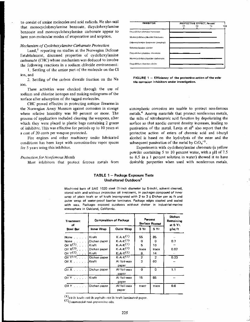
to consist of amine molecules and acid radicals. He also said
that monocyclohexylamine benzoate, dicyclohexylaminebenzoate and monocyclohexylamine carbonate appear tohave non-molecular modes of evaporation and sorption.
INHIBITOR
Dicyc10hexylamine benzoate
Monocyclohexylamine benzoate
PROTECTIVE EFFECT. Percent25 50 75 100
Mechanism of Cyclohexylamine Carbamate ProtectionLund,1 reporting on studies at the Norwegian Defense
Establishment, discussed properties of cyclohexylaminecarbamate (CHC) whose mechanism was deduced to involvethe following reactions in a sodium chloride environment:
1. Settling of the amine part of the molecule on the Clion, and
2. Settling of the carbon dioxide fraction on the Naion.
These activities were checked through the use ofsodium and chlorine isotopes and making radiograms of thesurface after adsorption of the tagged molecules.
CHC proved effective in protecting antique firearms inthe Norwegian Army Museum against corrosion in storagewhere relative humidity was 80 percent or more. Theprocess of application included cleaning the weapons, afterwhich they were placed in plastic bags containing 2 gramsof inhibitor. This was effective for periods up to 10 years ata cost of 20 cents per weapon protected.
Fire engines and other machinery under lubricatedconditions has been kept with corrosion-free vapor spacesfor 5 years using this inhibitor.
Protection for Nonferrous MetalsMost inhibitors that protect ferrous metals from
Dibenzylamine benzoate (neutral)
Dibenzylamine nitrite
Dicyclohexylamine chromate
Monocyc1ohexylamine carbonate
DicyclohexyJamine nitrite
FIGURE 1 - Efficiency of the protective action of the vola
tile corrosion inhibitors under investigation.
atmospheric corrosion are unable to protect non-ferrousmetals.4 Among materials that protect nonferrous metals,the salts of nitrobenzoic acid function by depolarizing thesurface so that anodic current density increases, leading to
passivation of the metal. Levin et al4 also report that theprotective action of esters of chromic acid and t-butylalcohol is based on the hydrolysis of the ester and thesubsequent passivation of the metal by Cr04 -2.
Experiments with cyclohexylamine chromate (a yellowpowder containing 5 to 10 percent water, with a pH of 7.5to 8.5 in a 1 percent solution in water) showed it to havedesirable properties when used with nonferrous metals.
TABLE 1 - Package Exposure TestsUnsheltered Outdoors2
Machined bars of SAE 1020 steel (l-inch diameter by 5-inchl, solvent cleaned,
stored with and without protective oil treatment, in packages composed of inner
wrap of plain kraft or of kraft impregnated with 2 to 3 g Oichan per sq ft and
outer wrap of water-proof barrier laminates. Package edges stapled and sealed
with wax. Packages exposed outdoors without shelter in industrial-marine
atmosphere in Oakland, California.
Oichan
Treatment
Composition of PackagePercentRemaining
of
Surface Rustedat 5 Yr.
Steel BarInner WrapOuter Wrap3 Yr5 Yrg/sq ft
None .....
KraftK-A-K(l)5585 -None .....
Oichan paperK-A-K(l)00 0.7
::lil X(2) ....KraftK-A-K(l)510 -
::lit X(2) ....Oichan paperK-A-K(l)tracetrace0.07
::lil y(2) ....KraftK-A-K(l)614 -
::lil y(2) ....Oichan paperK-A-K~l)22 0.23
::lil X .....
KraftAI foil-wax360 -paper
::lil X .....
Oichan paperAI foil-wax00 1.1
paper::lil Y .....
KraftAI foil-wax1585 -paper::lil Y .....
Oichan paperAI foil-waxtracetrace0.6
paper
(1)60Ib kraft-60 Ib asphaIt-60 Ib kraft laminated paper.
(2 )Commercial rust-preventive oils.
225

226
(21 g/m2 of wrapping paper)
TABLE 2 - Results of Accelerated Tests
with Cyclohexylamine Chromate4
Staining of Nonferrous Metals
One percent aqueous solutions of alkali bichromate or
Protection of Weapons and EnginesNaval small arms and 50 mm cannon did not corrode
after 10 years 7 outdoors when wrapped in vapor phaseinhibitor impregnated paper and then sealed in a dippedplastic envelope.
Reciprocating aircraft engines were protected by injection of about 75 grams of vapor phase inhibitor powderinto engine cavities. Test engines were deployed for storageover a wide range of environments. In comparison withsimilar engines protected by other preservative methods,the vapor phase inhibited specimens were in acceptablecondition after 18 months of outdoor storage while someof the others were not. During additional exposures up tothree years, samples of test engines were found to be ingood condition. After this time, however, cylinder wallsbegan to show corrosion damage.
Additional benefits are expected from improved inhibitors incorporating hydrobromic acid neutralizing additivesand small additions of more volatile compounds to giveearly protection.
Practical Applications ofVapor Phase Corrosion Inhibitors
Vapor phase inhibitors may be used to impregnatewrapping paper, or placed loosely inside a closed container.Either method has many applications for storage of small,large, or oddly shaped metal parts. The slow vaporization ofthe inhibitor furnishes protection against the air andmoisture which ordinarily will penetrate the package orenclosure. This technique is particularly effective when theitem is enclosed within a plastic "bubble".
Degree of Corrosion After Cycles No.Metals or Their Combinations
128248368488616
Carbon steel
00 0 00Aluminum(l)
00 0 00Nickel
00 0 00Zinc
00 1 00
Magnesium
00 0 3Cast Iron
00 0.008%0.018%Ti n in co ntact with cast iren
00 0 00Lead bronze
01 1 11Steel in contact with lead bronze
00 0 00Bronze AI-Mn
11 1 11
Babbit in contact with bronze
11 2 13
(I)Note: The corrosion scale for nonferrous metals is:O-Without change.1~Light tarnish, disappearing after wiping or washing.2-Tarnish that can be washed, or light interference calor.3-Stains or strips without distinct corrosion products.
Synthesized InhibitorsRosenfeld, Persiantseva and Polteva,s synthesized a
new class of vapor space inhibitors capable of protectingboth ferrous and nonferrous metals. Hexamethyleneimine
m-nitrobenzoate, one of the synthesized materials, is widely
used. They made additional tests which showed that otheramines such as dicyclohexylamine, butylamine, propylamine, monoethanolamine and diethanolamine can take the
place of hexamethyleneimine forming m-nitrobenzoates toprotect both ferrous and nonferrous metals.
By testing the saturated vapor pressures of thesematerials, they discovered that in concentrated sodiumsulfate solutions, aminobenzoates affect iron only slightly.The aminobenzoates are believed to passivate iron mainly
by increasing the cathodic reduction reaction of the nitrogroups. In dilute electrolytes they inhibit the anodicprocess.
Investigations by Agarwala and Tripath6 showed that
phenylthiourea gave four months' protection to steel,copper, brass and aluminum exposed to 100 percenthumidity under stagnant conditions. Mild steel was protected best by allyl thiourea; copper and brass by phenylthiourea. Aluminum was protected best by tetramethylthiourea monosulfide.
Accelerated tests were made under the following conditions:
1. 94 to 98 percent relative humidity,2. 0.01 mg/l sulfur dioxide,3. Temperature cycles every 3 hours, from 45 C to
room temperature.Microscopic examination of the surfaces gave the
results shown in Table 2.

chromate will confer resistance to tarnishing of copper andbrass sheets after immersion for 10 seconds to 2 minutes.
The sheets must be washed after dipping and thenforce-dried. 8
While mechanism of the protection is not fully understood, it is postulated that the treatment forms a layer ofchromate about 2 x 10⁻⁴ mm thick on the surface. Others
believe chromate ions are responsible for the protection.Slushing compounds with or without volatile solvents
or inhibitors also are used.
As shown in Figure 2, sodium chromate successfullyprotected aluminum sheets subject to attack by vaporsfrom the atmosphere.9
SummarySubstantial success in the vapor phase protection of
ferrous metals has been achieved using volatile amines andother polar substances. Proper care must be taken inpackaging to prevent the inhibitor from being lost to theoutside atmosphere. Inhibitors for nonferrous metals with
vapor space exposures have provided some degree ofprotection, but in many cases were not as effective as theinhibitors ll~ed with ferrous metals.
References1. L. Lund. Practical Uses of Vapor Phase Inhibitors, 3rd Europ.
Symp. on Cor. Inh., Ferrara, p875-9 (1970).2. A. Wachter, T. Skei and N. Stillm an. Corrosion Preventive
Packaging, Corrosion. 7, No. 9, 284-94 (1951) Sept.3. J. Mindowicz. An Investigation of the Mechanism of the Effect
of Certain Volatile Inhibitors on Corrosion, Proc. 3rd Int. CongoMet. Cor., Moscow, Vo!. 2, pi 70-7 (1966).
4. S. Z. Levin, S. A. Gintzberg, I. S. Dinner, and V. N. Kuchinsky.Synthesis and Protective Action of Some Inhibitors on the Basis
of Cyclohexylamine and Dicylcohexylamine, Proc. 2nd Europ.Symp. on Cor. Inh., Ferrara, p765-6 (1965).
5. I. L. Rosenfeld, V. P. Persiantseva, and M. N. Polteva. SomeTheoretical Aspects of Metal Protection Against Corrosion byVolatile Inhibitors, Proc. 4th Int. Congo Met. Cor., Amsterdam,NACE, Houston, Tx., p606-9 (1969).
6. V. S. Agarwala and K. C. Tripathi. Some Vapor Phase InhibitorExperiments, Mat. Pro .• 5, No. 12,26-7 (1966) Dec.
7. S. L. Chisholm and H. N. Rudd. Progress in Prevention ofCorrosion in Naval Aircraft, Corrosion, 13, No. 7, 47 3t-480t(1957) July.
227
FIGURE 2 - Panels from test racks in which aluminum
sheets were exposed to a 30 day high humidity test. Top: Noprotection. Center: Interleaved with untreated tissue paper.Bottom: Interleaved with tissue paper containing 1.5 to 3percent sodium chromate. Sheets were unoiled.8
8. E. Mattsson. Staining of Copper and Brass, Corrosion, 14, No. 2,88t-92t (1958) Feb.
9. C. C. Lacy and E. W. Everhart. Inhibited Interleaving TissuePrevents Water Staining of Aluminum, Corrosion, 9, No. 8, 295(1953) Aug.

J. M. SHARPLEY*
Microbiological Corrosion and Its Control
IntroductionCorrosion induced or accelerated by bacteria, fungi, orassorted higher invertebrates, is a recognized process. Theprocess is well established in the literature, as its aspectshave been reviewed by a number of authors.
However, it is probable that microbiological corrosionrarely occurs as an isolated phenomenon but, rather, iscoupled with some type of electrochemical corrosion. Forexample, corrosion induced by sulfate-reducing bacteriausually is complicated by the chemical action of sulfides.Corrosion by an aerobic organism, by definition, alwaysoccurs in the presence of oxygen. To further confound theproblem, microbiocidal chemicals also may have someconventional properties as corrosion inhibitors (e.g.; filmforming). There does not seem to be a published record of apractical corrosion problem that has been treated with abiocide that did not also have some physicochemical action.
The history of research on microbiological corrosion isinformative and reflects the degree of pragmatism found inresearch in that area. A few investigators have beeninterested in microbiological corrosion for about 30 years.In 1958 an informal survey indicated that throughout theworld there were about 20 people actually working andpublishing in the field. In 1962 there was a conference inWashington concerning microbiological corrosion and about250 persons indicated their interest and expertise. Thechange in interest level reflects the aircraft fuel corrosionproblem in 1961-1966 and the large amount of Federalmonies allocated to a solution of the problem. Microbiological corrosion in aircraft, with some major exceptions, isnow controlled by fuel additives, coatings and goodhousekeeping. Little research money is now available in thisspecific area and the literature shows a major decrease inpublications.
If one accepts the most general definition of corrosion,then microbiological corrosion has existed since man first
recovered metals from their ores. Microbiological corrosionwas suggested in 18911 and 1910.2 It is an exceedinglycommon process. The mud of a marsh is very deficient inoxygen and anaerobic bacteria will convert the availablesulfates to hydrogen sulfide. This, combined with othersulfur compounds, accounts for the typical odor found insuch areas. Any scrap ferrous metal present-or an unpro-
*Virginia Commonweal1h University, Fredericksburg, Va.
228
tected pipeline-will be attacked promptly as the result ofmicrobial activity.
Although, microbiological corrosion is important economically, the exact dollar value of the loss must awaitprecise quantification of biologically induced corrosion. Anumber of estimates of economic loss have been made.
Greathouse and Wessel3 estimated that biological corrosionof pipelines cost between $500 and $2000 million a year.In 1964 Booth4 estimated that at least 50 percent of thefailures of all buried metal was due to biological corrosion.So far as is known, no public figures are availableconcerning the loss from aircraft corrosion but they mustbe very large.
Organisms Involved in Corrosion ProcessesTwenty years ago, the author would have written a
section under this heading that contained a definitive list of"corrosion-causing bacteria", but this no longer is possible.Experience has shown that the basic knowledge concerningthe organisms is lacking. It can be said that when certaintypes of bacteria and fungi are found, biological corrosionis probable, but, at best, this is a rather negative statement.
As a result of this uncertainty, few positive statementsmay be made with scientific accuracy. However, it is knownthat biological corrosion is nearly always present wherelarge numbers of bacteria exist; i.e., a dirty or slimedsystem. The implication of such a system is that a largevariety of bacteria are present. The number of microorganisms, the variety of species and the substra te providedfor additional species all statistically increase the possibilityof strains occurring with corrosion inducing mechanisms.
An excellent in-depth discussion of the taxonomy oforganisms involved in corrosion processes has been providedrecently by Iverson.s His paper is strongly recommended tothe professional microbiologist.
In general, both fungi and bacteria have been implicated by many authors in microbiological corrosion. Thebulk of the publications probably concern the anaerobicsulfate-reducing bacteria; second, the aerobic, iron bacteriaand last, the fungi. Most microbiologists will readily agreethat in addition to those described in the literature, manyunrecognized microorganisms probably are involved incorrosion processes.
Theory of Biological CorrosionMany investigators regard microbial corrosion as a

specialized form of electrochemical corrosion. Unfortunately, some investigators without backgrounds in thebiological sciences have not recognized the dynamic systems that are always inherent with a living population.
For sake of convenience, the theories of biologicalcorrosion are divided into aerobic and anaerobic systems.
contact with sulfate-reducing bacteria, the cathode of thegalvanic cell is formed thus:
Anaerobic Co"osion
The fundamental paper concerning corrosion by sulfate-reducing bacteria is that of von Wolzogen Kuhr and L.S. van der Vlugt. 6 Although this remarkable paper waspublished in 1934, 35-odd years of examination have notshaken the foundation of the work.
In general the mechanism is as follows:When sulfate-reducing bacteria are present, the anode
of a galvanic cell may be formed thus:
Fe -+ Fe 2+ + 2e-
Figure 1 is a diagram showing some of the possiblereactions incident to the metabolism of sulfate reducingbacteria as they influence the corrosion of metals.
On metal surfaces such as ordinary iron or steel not in
The loss of electrons from the metal makes it anodic,with the iron going into solution:
Fe -+ Fe 2+ + 2e -
The free electrons thus formed migrate to the cathodeand react with hydrogen ions to form gaseous hydrogen:
The free ferrous ions then react with hydrogen sulfideformed at the anode to form free hydrogen ions and ferroussulfide. The hydrogen ions thus formed may either migrateto the cathode or react with hydroxyl groups to formwater. The free ions must react because they cannot remainin a free state.
The ferrous sulfide formed at the anode also will act
cathodically and release more ferrous ions, thus complicating the reaction.
Occasionally, chemical analyses of such systems do notshow the presence of sulfide but do identify other materials
S04= -+ S= + 40-+
8H + 40 -+ 4H20
2+ )3F~ _ ~ 3Fe(OH 2,--I Fe2+ __ ~ FeSr--
~ 60~_S= ---
Su Ifate Reducing Bacteria
t 8H
Metal
Medium
.:;:..--------------
+8(-) 8H-....J /
~ /,~-------------~--------~
Anode
FIGURE 1 - A diagram of the reactions incident to microbial corrosion caused by sulfate reducingbacteria.28
229

Mechanisms of Hydrogen Utilization by Bacteria
6 Days
18 Days
25 Days
1.0 2.0Current density MA/dm2
-1.0
FIGURE 2 - Cathode polarization curves illustrating theeffects of increasing incubation.28
'".;:;cQl•...oa.. -0 9Ql •"'Co...•...(.)Ql
W
-0.7
could not confirm a direct 1: 1 relationship betweenhydrogenase and rate of corrosion but did confirm a much
higher rate in the presence of hydrogenase. Horvath andNovae established polarization curves showing the changesin potential caused by sulfate-reducing bacteria. Thechanges of potential in sterile and inoculated culturesolutions were plotted against time. In a sterile solution
there was little change except a drift to the positive. Theslopes of the polarization curves indicate verification of the
cathodic depolarization theory proposed by von WolzogenKuhr.
The influence of incubation time on cathode polarization of specimens inoculated with bacteria is illustrated inFigure 2.
The publications of Booth, et al,12 confirm theconclusions above. However, this work is on much sounder
foundation in respect to microbial biochemistry; a significant weakness in the Horvath work. Booth and Tiller used
two strains of Desuifovibrio in their work. Both strains are
sulfate-reducing bacteria, i.e., obligate anaerobes obtainingenergy from the non assimilatory reduction of sulfates.However, D. desuifuricans (Hildenborough) contains ahydrogenase which permits it to utilize elementary hydrogen for the reduction of sulfate. D. orientis (Singapore) is asulfate-reducing bacterium with no hydrogenase.
Experimentally this is an important difference, since itis known that D. orientis (Singapore) cannot utilizeelementary hydrogen whereas D. desulfuricans does. In
wU(J)
:>
230
(2)
(3)
(5)
(4)
Much controversy has been centered around this mechanism of bacterial depolarization, since it is the basis of thetheory of microbial corrosion. In 1952, data published byWanklyn and Spruil8,9 proved most damaging to thetheory. It was shown that significant anodic depolarizationoccurred in the early stages of corrosion. This was causedby sulfide ions produced by the reduction of sulfate.Wanklyn and Spruit concluded that the anodic processrather than the cathodic depolarization is the rate determining step.
However, Horvath and Novacl 0,11 in 1960 and 1962
published data substantiating cathodic depolarization. Atthe same time and independently, Booth and Tillerl2published data that in turn substantiated the HorvathNovae paper. Subsequently Booth, Shinn and Wakelyl3
4H2 + 2C02-CH3COO- + H20 + H30+ + energy (1)Clostridium aceticum
This reaction is preceded by a reaction of the carbondioxide and water to form carbonic acid.
It is interesting that the formation of iron hydroxidealso can be postulated in this system by the reaction offerrous sulfide and hydroxyl ions thus:
Other common mechnisms of hydrogen utilization bybacteria are as follows:
hydrogenase2H2 + O2 • 2H20 + energy
such as oxides. If a water system contains free carbondioxide, then iron carbonate may form thus:
The cathodic depolarization step postulated in theoriginal work was based on the important series of papersby Stephenson and Strickland,7 who were the first toreport that hydrogen could be oxidized to water bybacteria. The enzymes involved in these reactions arehydrogenases. A simple example of the action is shown byHydrogenomonas facilis in the reaction
4H2 + CO2 -+ NH3 + 2H20 + OH- + energyMicrococcus denitrificans
2H2 + O2 -+ 2H20 + energyHydrogenomonas facilis
4H2 + 804= -+ S= + 4H20 + energyDesulfovibrio desulfuricans
4H2 + CO2 -+ C~ + 2H20 + energyMethanobacterium omelianskii

o 50 100Current density IJ.A/cm-2
FIGURE 4 - Polarization curves for mild steel at 30 C.Anode inoculated with D. Desulfuricans. 0-0 •• Initial curve._ •• After 2 days. -- •• After 7 days. -- •• After 10 days. 28
Anodic
Cathodic
Cathodic
o 50 100Current density, MA/CM-z
·0.8
·0.4
w()enen
.±::o> ·0.6cca'';::;cQ)•...oc..
-0.4
w()enen-
.±::o>.S -0.6ca'';::;cQ)•...oc..
-0.8
FIGURE 3 - Polarization curves for mild steel at 30 C.Cathode compartment inoculated with D. Orientis. 0--0 ••Initial curve. _ •• After 2 days. ••••• " After 10 days.28
It seems apparent that if it is accepted that a dense matof Gallionella can cause a differential aeration cell withconsequent pitting corrosion, the same effect could beexpected from any microorganism forming a dense growth.This was demonstrated by Sharpley20 working withSphaerotilus, a slime-formingiron bacterium and with otherslime-forming bacteria in water. Figure 5 illustrates theeffect of a differential oxygen cell created as the result of amat of biological depris deposited on steel.
Aerobic Co"osion Mechanisms
The volume of literature concerning the sulfatereducing bacteria has tended to obscure the role ofmicroorganisms in aerobic corrosion even though thenumber of oxygen-free aqueous environments in industry iscomparatively small. Conversely, because aerated aqueoussystems are common, aerobic bacteria may be involvedfrequently in microbial corrosion.
The theories of aerobic microbial corrosion are mostlycentered around the formation of concentration cells
showing differential aeration. Olsen and Szybalski17 madeuse of this theory in explaining the pitting corrosion causedby iron bacteria. Sharpley extended the observations to saltwater where a modified Gallionella was described and thisorganism is reasonably well established as the cause ofpitting corrosion in waters where iron bacteria occur. 18
One modification suggested by Olsen and Szybalski andconfirmed by Oppenheimer19 is the occurrence of sulfatereducing bacteria under the dense mats of Gallionella. Thiswould, of course, cause a type of anaerobic corrosion in awell aerated system.
addition it is known that the Hildenborough strain willutilize elemental hydrogen preferentially even if an organichydrogen donor is present. Thus, Booth and Tiller wereable to demonstrate that the variations in polarizationcurves correspond with the single factor of hydrogenasepresent or absent. Figures 3 and 4 illustrate the differencesin the reactions of these strains. The strongly anodicreaction attributed to D. Desulfuricans is readily apparentin Figure 4.
Polarization curves prepared with the organisms described are quite significant. Anodic and cathodic curves forD. orientis (Singapore) show no cathodic depolarization.These results are related to the absence of a hydrogenase.The depolarization exhibited when the organism is able toutilize hydrogen is clearly shown by strong cathodicdepolarization at 2 days, when the organism is growingwell. After la days, when the activity of the bacteria hasslowed through exhaustion of the nutrient, the curvereturns to much the same form as in the newly inoculatedculture.
Iverson14,15 obtained additional data indicating thatsulfate-reducing bacteria are directly involved in the corrosion rate reaction. Much of his work has been directlyconfirmed by the present author and indirectly confirmedby Booth and Tiller.16
There is no doubt that sulfate-reducing bacteria containing a hydrogenase constitute an active mechanism ofcorrosion, removing hydrogen and thus increasing currentflow in a corrosion cell. However, this is not the solemechanism. The depolarizing effect of iron sulfide accountsfor some of the high corrosion rates observed in the field. Itis important to remember that the original causativehydrogen sulfide may be produced microbially. This pointprobably is important when working with corrosion engineers whose background would tend to bias them towards apurely chemical corrosion mechanism. The problem is notsolvedso simply.
231

FIGURE 5 - Effects of microbiological corrosion of 1010steel.
Corrosion under aerobic conditions is also caused bymembers of the genus Thiobacillus. Damage caused bythese organisms is not common, but may be spectacular.Microbiologically, their growth may be quite complicated,21 but the corrosion mechanism is simple. They formsulfuric acid in their metabolism and the end concentration
may lie between 5 and 10%. Any material attacked bydilute sulfuric acid may be damaged. Concrete sewer pipes
are frequently damaged as the result of Thiobadllusactivity.
Thiobacillus fe"o"()xidans will oxidize natural pyritedeposits to produce high concentrations of sulfuric acid.Because pyrite deposits are often found in coal and goldmine tailings, the drainage from such deposits accounts forpollution known as acid mine drainage. For exampleSirnmons and Reed22 have reported pH levels at 3.0 inContrary Creek in Virginia as a result of the action of T.fe"ooxidans on mine tailings.
Bacteria and fungi produce a large number of organicacids through their metabolisms. The accumulation of suchacids would reasonably be expected to be corrosive and thiseffect has been reported several times. AlIen, et ai,23
232
reported corrosion by this mechanism in beet sugar mills in1948 and Appllng and Sharpley observed the same phenomenon in 1957 in Cuban cane mills.
The work previously discussed all has pertained tomicrobial corrosion of ferrous metals. In recent years thecorrosion of aluminum has received a great deal ofattention by the Air Force and its contractors. The problemat one time involved the structural integrity of aircraft andwas an important specialized problem although, from anoverall economic viewpoint, the corrosion of ferrous metalsis far more important. From a corrosion viewpoint, thisproblem is considerably confused by the involved microorganisms utilizing jet fuel as a carbon source. Bacterialproducts are produced in the form of sludge and thisfurther confused the issue.
Water must be present in the aircraft fuel for themicroorganisms to proliferate. Henrick, et ai,24 hypothesized that the bacteria in fuel tanks obtain their metal
requirement directly from the aluminum. In tests usingdeionized water, fuel and bacteria show a large increase incorrosion compared to the same system when uninoculated.,It is known that pure water is quite aggressive so, if oneassumes that water present in aircraft results from vaporcondensation, the water may indeed cause corrosion.However, water can be introduced into fuel from othersources and this water is far from pure. Hydraulic transferof fuel by sea water displacement is a classic example.However, Hendrick's data do not seem to be incompatiblewith simple bacterial concentration cell corrosion andappear reasonably applicable to some problems observed inpractice.
Blanchard, et ai,25 have published data indicating thatnitrate was an inhibitor of aluminum corrosion in much the
same manner as discussed by Uhlig26 on 18-8 steel.However, in retrospect it appears that the obvious
possibility of simple concentration cell corrosion appears tobe the most logical cause of microbial aluminum corrosion.Iverson27 has demonstrated the presence of sulfate-reducing bacteria in the depths of tubercles on aluminum.14Corrosion by metabolic by-products is certainly a possibility on both ferrous and nonferrous metals, but moreexperimental data are required to present a convincing casein the face of other evidence.
Recognition of Microbial Corrosion ProblemsIt seems safe to say that microbiologists generally feel
that many cases of microbial corrosion in industry gounrecognized. At the current state of knowledge it isreasonable to suspect microbial corrosion in the presence oflarge masses of microbial slime and probably in thepresence of large microbial populations. However, theseparameters are often unknown.
Microbial corrosion rarely occurs without at least somedegree of conventional corrosion. It is very difficult toseparate the two. The current state of knowledge necessi·tates the expediency of controlling or killing the microbiological growth and arbitrarily assuming the degree of
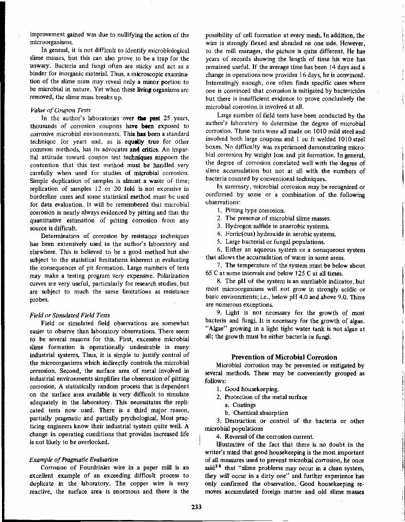
improvement gained was due to nullifying the action of themicroorganisms.
In general, it is not difficult to identify microbiologicalslime masses, but this can also prove to be a trap for theunwary. Bacteria and fungi often are sticky and act as abinder for inorganic material. Thus, a microscopic examination of the slime mass may reveal only a minor portion tobe microbial in nature. Yet when these 1ivin~organisms areremoved, the slime mass breaks up.
Value of Coupon Tests
In the author's laboratories over the past 25 years,thousands of corrosion coupons have been exposed tocorrosive microbial environments. This has been a standard
technique for years and, as is equally true for othercommon methods, has its advocates and critics. An impartial attitude toward coupon test techniques supports thecontention that this test method must be handled verycarefully when used for studies of microbial corrosion.Simple duplication of samples is almost a waste of time;replication of samples 12 or 20 fold is not excessive inborderline cases and some statistical method must be usedfor data evaluation. It will be remembered that microbial
corrosion is nearly always evidenced by pitting and that thequantitative estimation of pitting corrosion from anysource is difficult.
Determination of corrosion by resistance techniqueshas been extensively used in the author's laboratory andelsewhere. This is believed to be a good method but alsosubject to the statistical limitations inherent in evaluatingthe consequences of pit formation. Large numbers of testsmay make a testing program very expensive. Polarizationcurves are very useful, particularly for research studies, butare subject to much the same limitations as resistanceprobes.
Field or Simulated Field TestsField or simulated field observations are somewhat
easier to observe than laboratory observations. There seemto be several reasons for this. First, excessive microbial
slime formation is operationally undesirable in manyindustrial systems. Thus, it is simple to justify control ofthe microorganisms which indirectly controls the microbialcorrosion. Second, the surface area of metal involved inindustrial environments simplifies the observation of pittingcorrosion. A statistically random process that is dependenton the surface area available is very difficult to simulate
adequately in the laboratory. This necessitates the replicated tests now used. There is a third major reason,partially pragmatic and partially psychological. Most practicing engineers know their industrial system quite well. Achange in operating conditions that provides increased lifeis not likely to be overlooked.
Example of Pragmatic EvaluationCorrosion of Fourdrinier wire in a paper mill is an
excellent example of an exceeding difficult process toduplicate in the laboratory. The copper wire is veryreactive, the surface area is enormous and there is the
233
possibility of cell formation at every mesh. In addition, thewire is strongly flexed and abraded on one side. However,to the mill manager, the picture is quite different. He hasyears of records showing the length of time his wire hasremained useful. If the average time has been 14 days and achange in operations now provides 16 days, he is convinced.Interestingly enough, one often fmds specific cases whereone is convinced that corrosion is mitigated by bactericidesbut there is insufficient evidence to prove conclusively themicrobial corrosion is involved at all.
Large number of field tests have been conducted by theauthor's laboratory to determine the degree of microbialcorrosion. These tests were all made on 1010 mild steel and
involved both large coupons and 1 cu ft welded 1010 steelboxes. No difficulty was experienced demonstrating microbial corrosion by weight loss and pit formation. In general,the degree of corrosion correlated well with the degree ofslime accumulation but not at all with the numbers of
bacteria counted by conventional techniques.In summary, microbial corrosion may be recognized or
confirmed by some or a combination of the followingobservations:
1. Pitting type corrosion.2. The presence of microbial slime masses.3. Hydrogen sulfide in anaerobic systems.4. Ferric(ous) hydroxide in aerobic systems.5. Large bacterial or fungal populations.6. Either an aqueous system or a nonaqueous system
that allows the accumulation of water in some areas.
7. The temperature of the system must be below about65 C at some intervals and below 125 C at all times.
8. The pH of the system is an unreliable indicator, butmost microorganisms will not grow in strongly acidic orbasic environments; i.e., below pH 4.0 and above 9.0. Thereare numerous exceptions.
9. Light is not necessary for the growth of mostbacteria and fungi. It is necessary for the growth of algae."Algae" growing in a light tight water tank is not algae atall; the growth must be either bacteria or fungi.
Prevention of Microbial CorrosionMicrobial corrosion may be prevented or mitigated by
several methods. These may be convenien tly grouped asfollows:
1. Good housekeeping.2. Protection of the metal surface
a. Coatingsb. Chemical absorption
3. Destruction or control of the bacteria or other
microbial populations4. Reversal of the corrosion current.Illustrative of the fact that there is no doubt in the
writer's mirid that good housekeeping is the most importantof all measures used to prevent microbial corrosion, he oncesaid28 that "slime problems may occur in a clean system,they will occur in a dirty one" and further experience hasonly confirmed the observation. Good housekeeping removes accumulated foreign matter and old slime masses

that not only cause problems in themselves but provide anexcellent breeding place for future generations of microorganisms.
Although good h6usekeeping may be accomplished bya detergent, hot water and a scrub brush, it is a rare systemthat is accessible to this treatment. More frequently hotsolutions of detergents, with or without bactericides orother additives, are circulated through a system. Parenthetically, there is ample reason to suspect that several wellknown industrial biocides are primarily effective because oftheir surface-active characteristics and only secondarilybecause of their anti-microbial activity. Again, however, thepragmatist says "what difference, they work!"
There are some situations where it is impossible topractice good housekeeping. For example, the writer onceworked in Southern Illinois on a shallow buried water line
that was run through a large pig lot. Because the microbialpopulation and moisture level was such that any chemicaltreatment was impractical, it seemed to be an ideal placefor a coating to protect the exterior of the line. Suchcoatings are widely used and may consist either of the olderasphaltic types or of newer synthetics and although theyare subject to failure, as shown by Harris29 in a number ofpublications, they do indeed mitigate corrosion.
The interior surfaces of lines may be protected by aphysical coating such as asphalt, epoxy resins or cement.Although these coatings perform adequately when intact,they subject the underlying metal to accelerated pittingcorrosion at the sites of flaws and holidays. Consequently,protection of metal surfaces by a chemical barrier such asthat provided by the filming amines is a common practice.The carbon chain length of materials used in this fashion isimportant and a straight chain of 10 to 18 carbon atoms ismost effective. Octyldecylamine (with 18 carbons) isfrequently used. Such filming amines are effective butoccasionally have caused difficulties by forming sludge.
Other compounds are used to protect the surface fromchemical corrosion. Sodium silicate, polyphosphates, organic gums and chromate have been used, as have sulfurcompounds such as 2-mercaptobenzothiazol. From a microbiological point of view, these various compounds mayshow unexpected activities. Sodium silicate is probablyinert, but the addition of phosphates to a water system mayenhance microbial growth. Chromate may be quite undesirable. Contrary to popular opinion, chromate is generally ineffective as a bactericide and because of its high ioncharge density, it coagulates individual bacteria into largeslime masses. The alkali metal salts of 2-mercaptobenzothiazole are weak bactericides and seem especially activeonly with copper. More information on the effect ofbacteria will be found in the chapter in this book oncooling water.
Control of the microorganisms in a system is rarelyused alone for microbial corrosion control. Consequentlymixtures of compounds are commonly used to controlbacterial growth as well as corrosion caused by otherreactions.
For example, filming amines are most effective ascorrosion inhibitors at a chain length slightly greater than
234
that showing the greatest biocidal activity. Thus, one oftenfmds mixtures in use to accomplish both purposes. Organicsulfur compounds, in addition to their biocidal activity,also apparently provide some physical cleaning. Sincebiocides are so rarely used solely for the control ofmicrobial corrosion, it is often difficult to evaluate themproperly.
Cathodic protection is difficult to evaluate for muchthe same reasons. Corrosion is often quite severe beforesuch a system is employed and it is difficult to distinguishamong the initial forms of pitting corrosion. If the theoriesof microbial corrosion are correct, the imposition of aneutralizing current certainly should be effective.
In conclusion, it does not appear to the writer thataggregate knowledge has advanced rapidly concerning practical controls of microbial corrosion. All remedial tech
niques used in aqueous systems are troublesome, expensive,only partially effective, or all three. Better methods forrapidly identifying microbial corrosion in industry areneeded as badly as effective treatments are.
References1. J. H. Garrett. The Action of Water on Lead, H. K. Lewis,
London (1891).2. R. H. Gaines. Bacterial Activity as a Corrosion Influence in the
Soil, Jour. Engl. fnd. Chem., 2,128-30 (1910).3. G. A. Greathouse and C. J. Wessel. Deterioration of Materials,
Reinhold Publishers, New York (1954).4. G. H. Booth. Sulfur Bacteria in Relationship to Corrosion, Jour.
Appl. Bacteriol., 27, No. I, 174-81 (1964).5. W. P. Iverson. Biological Corrosion, In press (1972).6. C. A. H. von Wolzogen Kuhr and L. S. van der Vlugt.
Graphitization of Cast Iron as an Electro-biochemical Process inAnaerobic Soils, Water (Dutch) 18, No. 16, 147-65 (1934). C.A. H. von Wolzogen Kuhr. Unity of Anaerobic and AerobicIron Corrosion Process in the Soil, Corrosion, 17, No. 6,293t-299t (1961) June.
7. M. Stephenson and L. H. Strickland. Hydrogenase: A BacterialEnzyme Activating Molecular Hydrogen, I. Properties of theEnzyme, Biochemical Journa~ 25,206-14 (1931).
8. J. N. Wanklyn and C. J. P. Spruit. Iron/Sulfide Ratios inCorrosion by Sulfate-Reducing Bacteria, Nature (London), 168,951 (1951).
9. Influence of Sulphate-Reducing Bacteria on the CorrosionPotential of Iron. Nature (London), 169, 928 (1952).
10. J. Horvath. Contributions to the Mechanisms of AnaerobicMicrobiological Corrosion I. Acta Chemica, (Academiae Scientianum Hungaricae), 25, 65-79 (1960).
H. J. Horvath and M. Novac. Contributions to the Mechanism ofAnaerobic Microbiological Corrosion 11.,33,221-34 (1962).
12. G. H. Booth and A. K. Tiller. Polarization Studies of Mild Steelin Cultures of Sulphate-reducing Bacteria, Trans. Faraday Soc.,56, No. 11,1689-99 (1960).
13. G. H. Booth, P. M. Shinn and D. G. Wakerly. CongressInternational de la Corrosion Marine et de Salissures, (C.R.E.O.)Paris 363-71 (1964).
14. W. P. Iverson. Direct Evidence for the Cathodic DepolarizationTheory of Bacterial Corrosion, Science, 151, (3713), 986-88(1966).
15. W. P. Iverson. Corrosion of Iron and Formation of Iron
Phosphide by Desulfovibrio Desulfuricans, Nature, 217,1265-67 (1968).
16. G. H. Booth and A. K. Tiller. Cathodic Characteristics of MildSteel in Suspensions of Sulfate-Reducing Bacteria, Corros. Sci.,8,583-600 (1968).
17. E. Olsen and W. Szybalski. Aerobic Microbiological Corrosion

of Water Pipes, Co"osion, 6, No. 12,405-14 (1960), Reprintedfrom Acta Chemica Scandinavia, 3,1094-1116 (1946).
18. J. M. Sharpley. Occurrence of Gallionella in Salt Water, AppliedMicrobiology, 9,380-2 (1961).
19. C. H. Oppenheimer. How to Detect and Control CorrosionCausing Bacteria, World Oi~ 147, No. 7,144-7 (1958).
20. J. M. Sharpley. Microbiological Corrosion in Waterfloods,Co"osion, 17,92-6 (1961).
21. C. D. Parker. Species of SulCur Bacteria Associated With theCorrosion of Concrete, Nature, 159,439 (1947).
22. G. M. Simmons, Jr. and J. R. Reed, Jr. The EcologicalSignificance of Locating a Nuclear Powered Electrical Generating Facility on the North Anna River, Virginia, Proc. ThridNational Symposium on Radioecology, Oak Ridge, (In press).
23. 1. A. Allen. et al. Microbiological Problems in the Manufactureof Sugar From Beet. Pt. 1. Corrosion in the Diffusion Batteryand Recirculating Systems, Jour. Soc. Chem. loo., 67, 70-7(1948).
24. H. G. Hedrick, M. G. Crum, R. J. Reynolds, and S. C. Culver.Mechanism of Microbilogical Corrosion of Aluminum Alloys,Electrochem. Tech., 5, No. 3 & 4, 75-7 (1967).
25. G. C. Blanchard and C. R. Goucher. The Corrosion ofAluminum by Microbial Cultures, Dev. in Ind. Microbiol., 6,95-104 (1964).
26. H. H. Uhlig and J. R. Gilman. Pitting of 18-8 Stainless Steel inFerric Chloride Inhibited by Nitrates, Co"osion, 20, No. 9,289~292t(1964)SepL
27. W. P. Iverson. A Possible Role for SulCate Reducers in theCorrosion of Aluminum Alloys, Electrochem. Tech., 5, No. 38477-9 (1967).
235
28. J. M. Sharpley. Elementary Petroleum Microbiology, GulfPublishing Company, Houston, Texas (1966).
29. J. O. Harris. Bacterial Activity at the Bottom of Back-FilledPipe Line Ditches, Co"osion, 16, No. 3 149-54 (1960) Mar.
BibliographyG. A. Trautenberg. SulCate Reduction in Bacterial Corrosion, Mat.
Pro., 3, No. 2, 3134 (1964) Feb.R. N. Miller, W. C. Herron, A. G. Krigrens, J. 1. Cameron and B. M.
Terry. Research Program Shows Microorganisms Cause Corrosion in Aircraft Fuel Tanks, Mat. Pro., 3, No. 9, 60-7 (1964)Sept.
G. A. Trautenberg and A. C. Askew, Jr. Microbiological Control toPrevent Corrosion in Recirculating Water Systems, Mat. Pro., 3,No. 10,26-31 (1964) Oct.
S. Kaye and P. G. Bird. Measuring the Progress of Wood Rot inCooling Towers, Mat. Pro., 3, No. 10,46-50 (1964) Oct.
W. R. Scott. Bacterial Corrosion in a Waterflood System, Mat. Pro.,4, No. 2,57-62 (1965) Feb.
Y. Kunimoto. Sewer Corrosion Problems-The Honolulu System,Mat. Pro., 5, No. 11,8-11 (1966) Nov.
E. Tehle, Jr. SulCate Reducing Bacteria in Water Cooling Systems,Mat. Pro., 5, No. 12,21-2 (1966) Dec.
J. F. Conoby and T. M. Swan. Nitrite as a Corrosion InhibitorControlling Depletion of Sodium Nitrite, Mat. Pro., 6, No. 4,55-8 (1967) Apr.
D. R. Sexsmith and E. Q. PetreY. Laboratory Evaluation andApplication of On Stream Cleaning in Open Recirculating WaterCooling Systems, Mat. Pro., 10, No. 6, 13-8 (1971) June.

Controlling Corrosion in Pulp and Paper Mills
A. J. PI LUSO*
In every industrial process plant, corrosion is a big factorand often represents the difference between trouble-freeoperation, costly downtime and high capital expendituresfor replacement.
The corrosion that occurs in pulp and paper millsystems is caused by a variety of factors and chemicals and
isl especially prevalent in older systems. The paper industryhas been cognizant of high replacement costs and has knadesignificant strides in using more resistant materials ofconstruction. Such materials as stainless steel (300 to 400Series), and aluminum have gained widespread use becausethey are resistant to corrosive attack in many of theenvironments encountered in the manufacture of pulp andpaper. These materials are also beneficial because· theylessen contamination and discoloration of the product.
However, the problems of corrosion are still evident inpulp and paper mills and will significantly increase as millstend to close up their water systems. Reduction of waterlosses due to governmental restriction of mill effluents,recirculation of high-solid, "white" waters, increases intemperatures and velocities of these waters and greatermachine speeds all will contribute to the corrosivity of thesystems.
Published reports (Britt & Casey)I ,2 indicate thatdigesters in pulp mills corrode in varying degrees and thatthe attack is generally dependent on the corrosiveness ofthe liquor and/or varying operating conditions. The presence of chlorides, sulfates and carbonates in the kraft
"white" liquors can accelerate corrosion under certainconditions. Alkaline digesters are usually constructed ofcarbon steel because it is economical; however, stainless
steel liners or overlays are in widespread use. It is oftenfound that corrosion is practically negligible in digestersoperating continuously. However, recent data compiled byCanavan and Blanchard 3 show that average maintenancecost per unit year for both inclined and horizontal digestersis approximately $25,000. Evidence of corrosion and/orerosion is indicated by slight pitting at welds at the outletnozzles, wasting of the mid-feather and wear caused by theflights. They also state that the areas most frequentlyattacked are welds, top head of cones, bottom shell sectionand internal piping.
In neutral sulfite semi-chemical (NSSC) pulping operations corrosion is evident in digesters, conveyors, presses,
*Betz Laboratories, Philadelphia, Pa.
236
vacuum washers and other equipment servicing the system.Most of these units use stainless steel.
In multiple-effect evaporators, corrosion problems occur primarily in the first effect, due to the highlyconcentrated liquors and high temperatures in this effect.In storage tanks of the turpentine and tall oil recoverysystems, corrosion is caused primarily by hydrogen sulfide.
The mechanism of corrosion in certain stainless steel
alloys involves electrochemical reactions with anodic andcathodic areas. Each reaction is considered to be an
oxidation-reduction system. The electrolyte may vary frommoist air to strong acid.
Pitting Most Prevalent ProblemPitting-type corrosion is probably the most prevalent
type found in pulp and paper mill systems. Impingementattack, caused by a steady stream of solution impacting ona surface also is commonly found in these systems. Highsuspended solids and high temperatures aggravate this typeof attack. The abrasive action of the stream can remove the
oxide film on the surface, which causes the area to becomeanodic and corrosion to continue.
Galvanic corrosion occurs when dissimilar metals are in
electrical contact while immersed in an electrolyte. Stainless steel coupled with other metals will not corrode as longas the surface film of oxides on the stainless remains
unbroken and passive. If the stainless loses its passivity, dueto abrasion or scraping, severe attack can occur.
In many systems there is a defmite relationshipbetween pit formation and the location of deposits. In areaswhere the surface is relatively smooth, deposition seldomoccurs and usually there is no pit formation. However,where imperfections in the surface exist, such as atscratches, crevices, etc., nucleated pits are often observed.Build-up of fibrous deposits, slime and other material occurson these imperfect surfaces in stagnant and slow-flow areas.This build-up results in and contributes to corrosion.
A section of stainless steel plate taken from a large,white-water, collecting tank (Figure 1) shows characteristiccorrosion due to both concentration cell activity andmicrobiological corrosion. Salts, particularly chlorides andsulfates contributed to the corrosivity of the system. Theincidence of sulfate-reducing bacteria was extremely high.The raised weld areas and the abrasions on the metal
surface indicate concentration cell activity. The areas under

FIGURE l - Attack in zones beside weld bead acceleratedby bacterial factors. This section, taken from a large tank,shows characteristic corrosion due to concentration cells andmicrobiological· activity.
the deposits become anodic because of lack of oxygen. Ifthe corrosion products remain in the pits, attack can beaccelera ted.
Attack Resulting From Microbiological ActivityThese deposits also contribute to microbiological corro
sion problems in the presence of sulfate-reducing, iron andsulfur-oxidizing bacteria which will intensify the attack atthe metal interface through the formation of hydrogensulfide and other corrosive acids and gases.
The sulfate-reducers play a dual role in causing corrosion. First, they act as cathodic depolarizers and secondly,they produce hydrogen sulfide, which is corrosive.
In the process of corrosion by these organisms, ironloses electrons and enters the electrolyte as ferrous ion atthe anode. The electrons flow through the metal to thecathodic areas, where hydrogen gas is discharged, thehydrogen ions gaining an electron each and becomingneutral hydrogen atoms and eventually gaseous hydrogenmolecules. If hydrogen is not removed, the cell becomespolarized and corrosion ceases. In acidic solutions, depolarization takes place by the evolution of hydrogen gas. Inneutral or alkaline systems, oxygen can act as a cathodicdepolarizer.
In the case of slime and deposit accumulations, aerobicorganisms on the suface of the slime masses utilize theoxygen and release by-products which create an anaerobicstate at the metal interface. Thus, both aerobic andanaerobic organisms benefit by this association and/orcontribution. This type of union is known as com
mensalism. When oxygen is absent (or present in concen-
237
trations less than normal saturation, as in dense slimemasses or stagnant areas) ~e sulfate ion can serve as the
cathodic depolarizer. The sulfate-reducing bacteria consumehydmgen in their metabolic reduction of sulfate. This
bacterial action, which reduces the sulfate to sulfides, is!Jfought about the catalytic action of the enzyme hydrogenase present in the bacterial cell. The sulfide reacts with
the hydrogen to form hydrogen sulfide. Hydrogen sulfidewill then react with iron to form ferrous sulfide. Oxygenfrom the sulfate is made available for cathodic depolarization and corrosion continues.
The occurence of microbiological corrosion has been
observed in low-flow areas, stagnant chests, headboxes,save-all, press sections and other areas associated with slime,pitch, fatty acids and fibrous deposits.
The details of microbiological corrosion of iron andsteel have been reviewed by Cruickshank4 and the electro
chemical reactions of anaerobic corrosion in the presence ofsulfate reducing bacteria described by Von WolzogenKuhr.s
Briefly, the electrochernical reactions associated with
corrosion by sulfate-reducing bacteria can be explained bythe following equations.
I. Anodic dissolution leads to polarization of the
dissolving steel, while the neutralization of hydrogen ionsdepolarizes the steel.
Fe~Fe+++2(e)
2H+ + 2(e)~ 2H
2. In the presence of hydrogenase (bacterial enzyme),hydrogen adsorbed on steel surfaces reduces sulfates tosulfides.
8H + S04= ~ S= + 4H20
3. The dissolved iron may be hydrolyzed
Fe ++ + 60H- ~ 3Fe (OHh
4. The sulfide ion reacts with iron to form a sulfidedeposit
Iron sulfide deposits are characteristic of microbiological corrosion in the presence of sulfate-reducing bacteria.The overall reaction may be expressed as:
4Fe + 2H+ + S04 = + 2H2 0 ~ FeS + 3Fe (OHh
Microbiological Control MeasuresThere is a lack of correlation between bacteriological
examination and actual damage to a system resulting frommicrobiological corrosion. Although cultural techniquesused in the field and laboratories are extremely helpful,

238
TABLE 1 - Summary of Conditions and Results
Microbiological Corrosion in a Paper Mill
Biocide Anaerobe Count
Additions
AcidAerobe Count(SulfateCorrosionLocation
(ppm)pHProduction X 1000Reducers)(mils/yr)
Fresh WaterMakeup (1)
04.8 + 800150021.0
Beater Water Pit (2)
05.1+ 5500100039.9
(1 )
254.8+ 825100020.0(2)
255.1+ 342050022.5
(1 )
604.7+ 700100021.0(2)
605.5+ 1000 7017.0
1. Chlorophenates,2. Organic Nitrogen-base,3. Carbamates,4. Diamines,5. Heavy metal oxides,6. Sulfones,7. Thiocyanate-base,8. Acrolein,9. Copper salt complexes, and
10. Organic sulfur-based compounds.In any dynamic system, there are no simple single
foolproof tests.Usually, many indicators must be watched and fre
quently evaluated to determine if a given treatmentprogram is effective.
The seriousness of microbiological corrosion in papermill systems is often relegated to a secondary role inimportance, but a brief resume of a typical investigationand solution of the problem should be of interest.
Case History of Biological Attack
The mill in question was experiencing failure in lessthan three months of lines of the glands of Nash vacuumpumps, as well as of clarified water lines. The slime controlprogram in effect at the time was considered by operatingpersonnel to be adequate, in that few operational problemsattributable to slime were reported. Because slime waspractically nonexistent, the possibility of microbiologicalcorrosion was not considered.
An immediate investigation of the chemical and microbiological factors was undertaken. Corrosion rates in themill system were determined, not only to assess the severityof the problem, but also to serve as a reference point.
The corrosion rate for the fresh water make-up pit isconsidered normal for this supply. The beater water pitshowed an excessive corrosion rate.
Samples obtained from various points in the millsystem were checked for bacterial population levels, pH andacid production.
The correlation of the chemical factors and the
microbiological data led to the conclusion that micro-(1)A trade name of the Magna Corp., Santa Fe Springs, Ca!.
Microbiological TreatmentOnce the cause of the problem is ascertained, it
becomes necessary to determine the most effective andeconomical solution. Treating chemicals are available thatwill kill or inhibit the growth of harmful bacteria. General
ly, it is much more desirable to treat with an effectivebactericide than with a bacteriostat, since the probabilitythat a resistant strain of microbiological growth will
develop is greater with bacteriostatic agents.
I t is possible to test microbiocides in the laboratory toidentify the most effective compound that will effectivelycontrol the organisms. The use of dispersants and corrosioninhibitory chemicals is quite effective, but economicsusually favor the use of biocides for control. Goodhousekeeping methods dictate that before treatment, thesystem be cleansed of old corrosive films, scale deposits anddebris.
Laboratory testing on one particular species of sulfatereducing bacteria has demonstrated the inhibiting and/orkilling ability of several bactericides in the followingdescending order of effectiveness for various compounds:
they identify only the organisms that are present in thestream sample. These organisms can and often do, have acompletely different and unknown relationship to othermicroorganisms deposited on the sides of lines, pipes andequipment. It is these latter organisms that are the cause ofmicrobiological corrosion.
Electrical resistance probes, such as the Corrosometer, (1)redox potential determination, mineral analysis and corrosion test coupons are very helpful in determining corrosionprobabilities. However, results of these test methods cannotbe correlated with the number of sulfate-reducing bacteriathat will create a corrosion problem in a given system. Thesignificant fact when these organisms are present is that thepossibility for microbiological corrosion is developed. Cultural, direct microscopic and visual examination of these
systems and deposits must be relied on to ascertain ifbacterial corrosion is occuring.
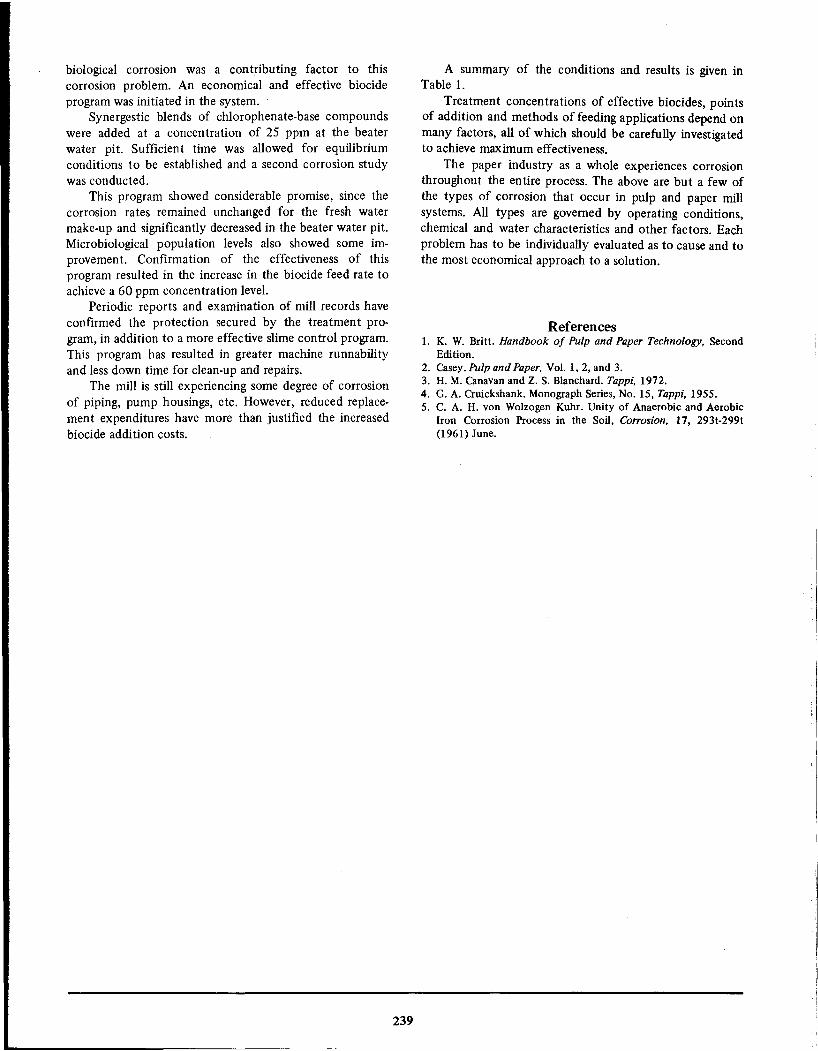
biological corrosion was a contributing factor to thiscorrosion problem. An economical and effective biocideprogram was initiated in the system.
Synergestic blends of chlorophenate-base compoundswere added at a concentration of 25 ppm at the beaterwater pit. Sufficient time was allowed for equilibriumconditions to be established and a second corrosion studywas conducted.
This program showed considerable promise, since thecorrosion rates remained unchanged for the fresh watermake-up and significantly decreased in the beater water pit.Microbiological population levels also showed some improvement. Confirmation of the effectiveness of thisprogram resulted in the increase in the biocide feed rate toachieve a 60 ppm concentration level.
Periodic reports and examination of mill records haveconfirmed the protection secured by the treatment program, in addition to a more effective slime control program.This program has resulted in greater machine runnabilityand less down time for clean-up and repairs.
The mill is still experiencing some degree of corrosionof piping, pump housings, etc. However, reduced replacement expenditures have more than justified the increasedbiocide addition costs.
239
A summary of the conditions and results is given inTable 1.
Treatment concentrations of effective biocides, pointsof addition and methods of feeding applications depend onmany factors, all of which should be carefully investigatedto achieve maximum effectiveness.
The paper industry as a whole experiences corrosionthroughout the entire process. The above are but a few of
the types of corrosion that occur in pulp and paper millsystems. All types are governed by operating conditions,chemical and water characteristics and other factors. Eachproblem has to be individually evaluated as to cause and tothe most economical approach to a solution.
References1. K. W. Britt. Handbook of Pulp and Paper Technology, Second
Edition.
2. Casey. Pulp and Paper, Vo!. 1,2, and 3.3. H. M. Canavan and Z. S. Blanchard. Tappi, 1972.4. G. A. Cruickshank. Monograph Series, No. 15, Tappi, 1955.5. C. A. H. von Wolzogen Kuhr. Unity of Anaerobic and Aerobic
Iron Corrosion Process in the Soil, Corrosion, 17, 293t-299t(1961) June.

A.H. ROEBUCK*
Inhibition of Aluminum
Protection of Aluminum by InhibitorsAluminum, an amphoteric metal, is subject to attack inboth strongly acid and strongly alkaline solutions. In the"essentially neutral range (pH 4.5 to 8.5) little, if any,attack occurs in the absence of 'heavy metal contamination'or galvanic effects. Outside this range, attack may occurdepending more on the specific ions which are present thanon the absolute value of pH." 1 Under essentially neutralconditions, Al can suffer localized pitting which may beobserved on articles such as aluminum window casementsand similar items where surface oxide breakdown has
occurred. Such attack is more prevalent along the seacoastsor in other areas with high humidity.
Chromates, silicates, polyphosphates, soluble oils andother inhibitors are commonly used to protect aluminum.Aluminum is concentration-sensitive to chromate solutionsas well as to other anodic inhibitors. Combinations of
polyphosphates, nitrites, nitrates, borates, silicates andmercaptobenzothiazole are used in systems that includealuminum and other metals. 1
Aluminum Alloy CompositionAluminum alloys containing copper (2000 series) and
zinc (7000 series) as major alloying elements are generallyless corrosion-resistant than those without these elements.
For this reason, these two series are usually more difficultto inhibit. Both are high-strength and widely used.
Attack can be prevented or reduced by cladding with amore corrosion-resistant alloy such as high purity aluminum, a low magnesium-silicon alloy or an alloy of I% zinc.All of these cladding materials are frequently employed togive added corrosion protection to the 2000 and 7000series alloys. The cladding on each side is 2 to 5% of thetotal thickness.
1000 Series Alloys: 99 percent pure aluminum or higher.This series has excellent resistance to corrosion and highelectrical and thermal conductivities, but poor mechanicalproperties.
2000 Series Alloys: Copper-containing alloys. This series ishigh-strength and heat-treatable, but has generally lowcorrosion resistance, is subject to intergranular attack and isdifficult to inhibit. The 2024 alloy is widely used in theaircraft industry.
• FuJlerton, Ca.
240
3000 Series Alloys: Manganese-containing alloys. This seriesgenerally cannot be heat-treated. One of the most widelyused alloys, 3003, has moderate strength, good workabilityand can be inhibited in certain media.
4000 Series Alloys: Silicon-containing alloys, used mainlyfor welding because of their lower melting points. Recentlyhave been in greater demand for architectural uses becauseof the color effects which can be obtained when anodic
coatings are applied. This alloy series has good corrosionresistance and can be inhibited.
5000 Series Alloys: Magnesium-containing alloys. They arecorrosion-resistant alloys which can be inhibited and arewidely used in marine atmospheres, where they exhibitgood resistance to attack. However, under certain conditions of loading, they are subject to stress corrosioncracking.
6000 Series Alloys: Silicon and magnesium-containingalloys. The silicon and magnesium are present in theapproximate ratio to form magnesium silicide, which isheat-treatable. A major alloy in this series is 6061. Thesealloys have good corrosion resistance and may be inhibitedeffectively.
7000 Series Alloys: Zinc-containing alloys. Also maycontain smaller percentages of magnesium, copper andchromium. They are heat treatable and can have very highstrengths, e.g., 7075, which is one of the highest-strengthaluminum alloys. Inhibitors may be used with the 7000series.
The solution heat treated tempers are usually more corrosion resistant and more amenable to corrosion inhibition than
are the hardened alloys. The strain or work-hardened alloysare somewhat more readily inhibited than are the alloyshardened by aging treatments.
Generally, the more homogeneous the alloy, the morereadily it can be inhibited and the higher its corrosionresistance. Temper treatments which promote homogeneityfor an alloying system enhance corrosion resistance and thealloys' ability to be effectively inhibited. Conversely,temper treatments which promote segregation, precipitation and non-homogeneity detract from the alloys' corrosion resistance and the ease with which it can be inhibited.

TABLE 1- Classification of Inhibitor
Types for Aluminum
Inorganic
Oxidizi ng: Chromate, nitrite, permanganateCationic: Mg2+,Ca2+, Ni2+Anionic: Molybdate, Si03-, W04-' Te04-
Organic
Macromolecules-Proteins: Agar-agar, albumin, casein, glucoseAmines: Acridine, hexamethylene tetramine, alkyl aminesAcids: Stearic acid, nicotinic acid, sulfonic acidOthers: Thiourea, nitrochlorobenzene
Aluminum Inhibitor TypesInhibitors for aluminum may be classified chemically asI. Inorganic, or2. Organic,They may also be classified by surface reactivity as1. Adsorptive, or2. Surface-reactive (where a precipitated mm is formed
to provide a barrier between the corrosive agent and thealuminum surface).
For purposes of this discussion the first classificationsystem will be used, inhibitors being divided into inorganicand organic types as shown in Table 1.
Film Destruction is Corrosion ReactionA mechanism of aluminum corrosion deduced by Boies
and Northan2 from tests made in wjo 62.5 ethylene glycoland 37.5 distilled water involves:
1. A period during which surface oxides are destroyed,hydrogen is evolved and an alkaline environment formed.
2. Film repair by oxygen in the solution until it isexhausted.
They concluded that under the test conditions, theanodic reaction of metal dissolution to form aluminum ionsoccurs at the interface between the metal and an amor
phous oxide layer; that aluminum ions diffuse outwardbecause of the concentration gradient; and also thatelectrons flow outward because of the potential differencebetween anodic and cathodic reacting sites.
"In any case, reaction of aluminum with water to formnon protective oxide and hydrogen proceeds rapidly oncethis barrier layer is destroyed", they said, discussing thethin amorphous barrier layer next to the aluminum.
In giving the results from tests with many inhibitors,Boies and Northan concluded:
1. Simple buffering is not the entire solution.2. Inclusion of ions from the inhibitor in the protec
tive mm on the aluminum is important.3. Steric configuration of the inhibitor ions is impor
tant.
4. Structures capable of forming chelate-type, ringconfigurations are more effective than those that cannot.
Good performance was obtained using non-ionic sorbitan fatty esters,
TABLE 2 - Protection by Inhibitors in Antifreeze Solutions(1)3.mg Loss
Water and I Water andWaterEthyleneIsopropyl
InhibitorIAlone GlycolAlcohol
Sodium silicate, 3.0 percent .... 1
10 4(2)
Sodium dichromate, 0.625 percent .
060 0Soluble oil and TSP, 3.0 percent .
83 0Sodium hydrogen phosphate, 0.03 percent
........... J17 030
(I)Test Solution-Royal Oak tap water; Length of Test-SOO hours;Velocity-2000 rpm; Temperature-ISO F.
(2)Inhibitor not compatible with alcohol solution.
Inhibitors Tested forPerformance at High Fluid Velocities
Accelerated tests of aluminum-clad sheet, similar tosheet used in fabrication of automobile radiators, weremade in natural waters and in automotive antifreezes3 at
velocities up to 4700 fpm. Materials tested were sodiumpyrophosphate, tartaric acid, sodium borate, sodium ben
zoate, sodium nitrite, disodium hydrogen phosphate, sodium silicate; an unidentified inhibitor containing sodium andchromium; an oil emulsion consisting of 25 percenttrisodium phosphate and 25 percent oil in water; sodiumdichromate; buffer consisting of 2 M potassium dihydrogenphosphate, 55 percent and 2 M sodium hydroxide, 45percent; soluble oil, 33 percent and buffer (as shownabove), 67 percent.
Table 2 shows results using four inhibitive solutions
selected by screening tests. Disodium hydrogen phosphateapparently promoted pitting of the clad aluminum inalcohol solutions. Sodium silicate proved to be incompatible. Tests with soluble-oil solutions showed it to be veryeffective in high velocity water, less so in lower velocity anddeleterious in static water. In 1: I water-ethylene glycol,however, the soluble oil-buffer inhibitor reduced corrosion
to zero. Soluble-oil solutions proved effective at pH 6;satisfactory at pH 8, but ineffective at pH 10. It wasconcluded that a buffer to adjust pH would be helpfulwhen this solution was used.
Inhibitors Listed for WideRange of Corrosive Solutions
Roebuck and Pritchett,4 in citing their conclusions ona large volume of data concerning inhibition of aluminumsaid that gel-type inhibitors, such as agar-agar blockcathodic reactions, causing marked cathodic polarization.Amine inhibitors also influence cathodic reactions and
probably are useful in acid media. They pointed out alsothat nickel chromates (NiCr04) are more effective thanpotassium chromates, an indication that the effectiveness ofchromates was due to the Ni2 + ion and the geometry of theNiCr04 molecule and not due solely to their oxidizingability.
Data are given in Table 3 from a large number ofinhibitor tests and applications.
241
I .,1

15
FIGURE 1 - Inhibiting 7075 aluminum corrosion in 5percent sodium chloride concentrations. 5
Other EnvironmentsHydrofluoric acid is an effective inhibitor for alumi
num in concentrated nitric or sulfuric acid at hightemperatures.9 Silicates with a high ratio of silicate to sodaare used in alkaline cleaners, soaps and dentifrices containing amines, carbonates and phosphates.
Inhibition in Hydrochloric AcidAs reported by Unni and Rama Char,? aluminum,
which ordinarily corrodes at rates in excess of 0.05 ipy inboth aerated and unaerated hydrochloric acid at 24 C from10 to 40 percent concentrations in waterS can be protectedup to 98 percent under some conditions. Inhibitor efficiency with no, Di-ni- and Tri-n-Butylamines increased withacid concentration up to 1.25 or 1.5 N, depending on theinhibitor and was essentially constant at greater concentrations.
Figure 2 shows efficiencies achieved using the threeinhibitors.
Unni and Rama Char theorized that protection by theamines was due to their adsorption on cathodic areas .
SummaryPresent knowledge makes possible the inhibition of
aluminum in a wide range of both acidic and alkalineenvironments. Single materials and combinations have beenidentified that can be used with considerable confidence,
frequently, however, within a narrow range of conditions.Composition differences among aluminum alloys often
determine whether or not an alloy can be inhibited in agiven environment, so an understanding of the metallurgicalvariables is important. Recent investigations into thefundamental reactions at the aluminum-environment inter
face have added significant new understanding of some ofthe reactions there. This understanding will permit theselection of inhibitors to be made with greater precisionand their application to proceed with fewer trial-and-erroradjustments.
References1. E. D. Verink and D. B. Bird. Designing With Aluminum, Alloys
for Various Corrosive Environments, Mat. Pro., 6, No. 2, 28-30(1967) Feb.
2. D. B. Boies and B. J. Northan. Aluminum Corrosion: Possible
When the results were projected into estimates of theservice life of aluminum underground, best performancewas recorded by a treatment involving a chromate conversion coating plus application of petroleum jelly containing1 percent Na2 Cr04' Projected life of this treatment in acidmedia was 76.9 years; in neutral media, 400 years and inalkaline media 166.7 years.
Tests made of galvanic couples between steel andaluminum in the same media indicated that 40-year
corrosion rates for steel coupled to aluminum coated withpetroleum jelly containing 1 percent Na2 Cr04 were asfollows: pH 3, 0.38; pH 6.4, 0.19; pH 10, 0.05 mils peryear.
242
2.0
1.5
1.0 1.5
Acid Concentration, N
0.5
Percent Sodium Chromate
o
5
o
IIIIII.2•.....r::.Cl'Q)
:s:
40
0.5
•...c:QltJ
~ 80>tJc:Ql
'u~.•..w
<5 60•...:0:cc:
100
"0 10"0E
FIGURE 2 - Effect of acid concentration on inhibitorefficiency. Inhibitor concentration refers to g/I of nitrogenthroughout. Time: 2 hr; cone. 0.5 g/I; a = n-Butylamine. b =
di-n-Butylamine. c = tri-n-Butylamine.
Long Protection Times EstimatedWith Chromates
An evaluation of the effectiveness of chromate inhibi
tors in protecting aluminum in acid, neutral and alkalineenvironments was made using potentiostatic methods.6Acid media were at pH 3, neutral, at 6.4 and alkaline at 10.
Best and McGrew5 found that aluminum expo.sed to 5
percent sodium chloride was almost completely protectedby 2.0 percent concentrations of sodium chromate. Figure1 shows some of their data.

TABLE 3 -Inhibitors for Aluminum
in Corrosive Solutions4
Environment
InhibitorEnvironmentInhibitor
Acid, hydrochloric, 1N
0.003M aphenylacridine,Lead paint pigmentsLinoleates, laurates or
{3 naphthoquinone, thiourea, oror lead soapsricinoleates
2-phenylquinoline Acid, hydrochloric, 1N
Tannic acid or rosinMagnesium oxychlorideSodium chromate
Methanol or ethylene glycol
0.01-2% benzotriazole +
Acid, hydrochloric, 0.25, 1N
0.5 g/I acridine, 1.0 g/l 0.1-2% Na molybdate or
(32 F)
thiourea, or nicotinic acid arsenate or arsinite +
Acid, hydrochloric, 2N
0.06% acridine 0.5-2.5% buffer to
Acid, nitric, 2-5%
0.05% hexamethylene tetramine pH 7.5-10.5
Acid, nitric, 10%
0.1% hexamethylene tetramineMethyl alcoholSodium chlorate + sodium
Acid, nitric, 10%
0.1 % alkali chromate nitrate
Acid, nitric, 20%
0.5% hexamethylene tetramineMethyl chlorideWater
Acid, nitric, fuming
0.6% ammonium hexafluoro-Polyalkene glycol fluids2% Emery's dimer acid
phosphate
(dilinoleic acid), 1.25%
Acid, phosphoric, 20%
0.5% sodium chromate Na(CHME2)3,0.05-2%
Acid, phosphoric, 20-80%
1.0% sodium chromate mercaptobenzothiazole
Acid, sulfuric, conc.
5.0% sodium chromate
Alcohol, anhydrous
Trace of H2OPotassium cyanide1-5% sodium silicate
Sea water0.75% sec. amyl stearate
Alcohol, (antifreeze)
Sodium nitrite andSodium acetateAlkali silicates
(See also methyl and ethyl)
sodium molybdate
Ammonia, condensing steam
H2SSodium carbonate, dil.Sodium fluosilicate
Sodium carbonate, 1%
0.2% sodium silicate
Bromine water
Sodium silicateSodium carbonate, 10%0.05% sodium silicate
Bromoform
AminesSodium chloride, 3.5%1% sodium chromate
Calcium chloride, sat.
AI kali sil icates
Carbon tetrachloride
0.02-0.05% formamideSodium hydroxide, 1%Alkali silicates
Sodium hydroxide, 1%
3-4% potassium permanganate
Chlorinated aromatics
0.1-2.0% nitrochlorobenzeneSodium hydroxide, 4%18% glucose
Chlorine water
Sodium silicateSodium hydroxide, 0.3N (35 Cl0.4% tragacanth gum
Ethanol, commercial
0.03% alkali carbonate,Sodium hydroxide, 0.5N0.2% agar-agar
lactates, acetates or borates Sodium hypochlorite
Sodium silicate
Ethanol, hot
Potassium dichromatecontained in bleaches
Ethyl alcohol or
1% (NaN02 + Na molybdate),Sodium sulfideSulfur
ethylene glycol
1% (NaN02 + Na tungstatel, orSodium sulfide1% sodium metrasilicate
1% (NaN02 + Na selenate) Sodium trichloroacetate soln.0.5% sodium dichromate +
Ethylene glycol
Sodium tungstate or oil layer
sodium molybdate Sodium trichloroacetate,
0.5% sodium dichromate,
Ethylene glycol
Alkali borates or phosphates50% soln.
Ethylene glycol
0.01-1.0% sodium nitrate
Synthetic detergents
Sodium sil icate
Glycol-water, 30: 70
2% sodium cinnamate +Trichloroethylene0.02-0.05% formamide
0.1 % sodium tetrasilicate + phosphoric acid to pH = 9.5
Water-recirculating0.1 % Na2 Cr04, pH = 7-9, orfor air conditioning
0.1 % Na metasilicate + 0.1 %
Hydrogen peroxide
Alkali metal nitrates Na polyphosphate, pH =
Hydrogen peroxide
Sodium metasilicate 8.5-9.5
Hydrogen peroxide, alkaline
Sodium silicate
I..
Mechanisms of Inhibition, Mat. Pro., 7, No. 11, 27-30 (1968)
2-Development of a Corrosion Inhibitor, Corrosion, 12, No. 7,
Nov.
311t-316t (1956) July.,3. S.
B.TwissandJ.D.Buttenplan.Corrosion Testing of4. A. H. Roebuck and T. R. Pritchett. Corrosion InhIbitors for
Aluminum, Part
I-High Velocity Test Method in AqueousAluminum, Mat. Pro., S,No. 7,16-19 (1966) July.
Solutions, Corrosion,
12, No. 6, 263t-270t (1956) June. Part5. G. E. Best and J. W. McGrew. Inhibiting Corrosion of Steel,
243

Aluminum and Magnesium Intermittently Exposed to Brines,Co"osion, 12, No. 6, 286t-292t (1956) June.
6. G. Schick. Effects of Inhibitors on Aluminum Shield in
Telephone Cable Sheaths, Corrosion/72 Preprint No. 107,NACE, Houston, Texas.
7. V. K. Unni and T. L. Rama Char. Inhibition of Aluminum
244
Corrosion in Hydrochloric Acid by no, Di-n-, and Tri-n-butylamines,Co"osion, 22, No. 2, 53-59 (1966) Feb.
8. Corrosion Data Survey. NACE, Houston, Texas, page H-2 (1967).9. K. R. Van Horn, editor. Aluminum, VoL l-Properties, Physical
Metallurgy and Phase Diagrams, American Society for Metals,Metals Park, Ohio, p249 (1967).

Inhibition of Corrosion From Caustic Attack
A.H. ROEBUCK*
IntroductionAttacks on materials by solutions in the caustic range arewell documented. The fundamental reactions which cause
caustic attack are reasonably well understood, especially foriron,l aluminum2 and copper3 and there is a consensus onthe manner in which inhibitors protect or fail to protectSOmemetal surfaces exposed to alkaline environments.
Although many compounds can reduce alkaline corrosion rates, there are few really effective alkaline corrosioninhibitors. That is to say, most surface-active compoundswill reduce the corrosion rate to at least some extent, butthere are few that will reduce the rate enough to beeconomically useful. This is particularly true for the activemetals and the amphoteric metals, under moderately andstrongly alkaline conditions.
Among the most effective alkaline inhibitors are thegels such as pectin, agar-agar, etc. They function byblocking the surface and greatly decreasing diffusion ratesof reactants to the surface and corrosion products awayfrom the surface.
Against concentrated alkalies adsorption inhibitors are
not usually ef~ective unless they are present with solubleoils or blocking type inhibitors. Reactive or "chemi-sorbed"inhibitors are more effective, as are also inhibitors whichmodify the environmen t, such as sodium nitrite or glucosein an alkaline environment with brass.
Reinoehl4 says that "caustic cracking (of mild steel)may occur from NaOH concentrations as low as 4 percentup to values as high as 75 percent. With respect to causticcracking, he theorizes that corrosion by alkalies is the resultof unstable conditions at the metal-environment interface
such that protective layers of corrosion products areformed that incompletely cover the surface. This producesan active-passive state in which anodic zones, small in areawith respect to cathodic zones, corrode at accelerated rates.Gilroy and Mayne1 say "it is well known that ferroushydroxide becomes a strong reducing agent in alkalinesolutions" and, "However, in alkaline solutions the solubility of ferrous hydroxide is low."I
Reinoehl4 shows that caustic cracking (the mostcatastrophic form of alkali failure) occurs "in the transitionzone between the onset of passivation and its completion,when a relatively nonprotective film of divalent ironcorrosion product can coexist with a relatively protectivefilm of trivalent iron."
• Fullerton, Ca.
245
Inhibitor practice leans toward accomplishing one ormore of the following objectives:
1. Masking the anodic zones with a protective fIlm.2. Masking the cathodic zones with a protective fIlm.3. Masking both zones with a protective film.4. Producing a surface state such that corrosion is
general and uniform rather than concentrated and specificand thus avoiding stress cracking.
Extent of Corrosion by Alkaline SolutionsCorrosion by caustics occurs over a wide range of
environments and end products and in numerous industriesand applications. In addition to concentration, the factorscommonly indluencing rates in other corroding systems aresignificant to a lesser or greater degree. A report by anNACE Technical Practices Committee in 19515 tabulates82 case histories in which alkali corrosion failure occurred
in intervals from as little as 3 days to an extreme of nofailure in 15 years. The wide time range of these exposuresillustrates the anomalies that result from varying environments and operating conditions.
This same report gives twelve additional case historiesof corrosion by alkalies other than sodium hydroxide, suchas potassium hydroxide, sodium sulfate, calcium hydroxideand others. In these cases, failures occurred at times varyingfrom two months to 25 years.
In addition to many reports of alkali corrosion inaqueous solutions, numerous data have accumulated withrespect to the performance of metals exposed to nonaqueous alkalies, usually at the fairly high temperaturesassociated with combustion or atomic energy installations.Voluminous data are available on the corrosive effects of
various liquid metals at temperatures and pressures associated with atomic energy installations. Metals tested includesodium, lithium, potassium, lead, tin, mercury, bismuth,cadmium and mixtures of some of these. Because the
solutions of the corrosion problems incident to theseinstallations cannot be solved with inhibitors as commonlyconsidered, these environments will not be disucssedfurther.
Metallurgical systems susceptible to caustic attack maybe described as follows:
1. Many metals above hydrogen in the EMF series(general attack).
2. Many metals subject to pitting and crevice attack(localized attack).
3. All very active metals, e.g., Na, Li, Cs, Ca, Mg, AI.

TABLE 1 - Characteristic Alkaline Systemsand Related pH
Alkalinity[OH-] moles/literpH
I.
Slightly Alkaline 10-6,10-5,10-48,9,1011.
Moderately Alkaline10-3,10-2,10-!11,12,13Ill.
Strongly Alkaline-0
14, --10,or1,2,3
FIGURE 1 - Mild steel corroded in aerated 0.5 N NaOH at
250 C. A magnetite layer with parallel cracks in it and Fe203platelets with more amorphous Fe203 between them wasdeveloped. (Figure 29. Ref. 8)
4. All metals which are amphoteric in nature, Le.,metals which exhibit acidic characteristics in the presenceof a base and basic or alkaline characteristics in the
presence of an acid, e,g., Al, Zn, Pb.5. Metals having protective oxide films which are
broken down or disrupted in the presence of alkalinity.Table 1 is a rough categorization of alkaline systems
with related pH values.
Corrosion Reactions of Ferrous AlloysIn the case of materials exposed to caustic solutions at
high temperatures and pressures, data reported by Latanision and Staehle6 are interesting. They showed that invarious concentrations of sodium and potassium hydroxideat temperatures of 300 C and pressures of 3 x 10⁴ psi, thelife of Type 347 steel ranged from a little over one hour tomore than 500 hours.
Failures of austenitic stainless steels (304, 304 L) in 50
percent sodium hydroxide are transgranular at 150 to 370C (300 to 700 F) and the time to failure decreases astemperature increases. In 10 percent sodium hydroxidesolutions at 315 C (600 F) failures in these alloys areintergranular.7 All 316 and 316 L steels failed in 50 percentsolutions at these same temperatures as well as in 10percent sodium hydroxide at 315 C (600 F). Heattreatment did not influence time to failure. Molybdenumcontaining 316 steels appeared to be more susceptible tocracking than the 304 steels.
246
Similarity of the results indicates carbon content haslittle effect on cracking susceptibility.
Huybrechts, Van Osch and Snel8 concluded, after aseries of experiments with various concentrations of sodiumhydroxide, that the corrosion mechanism in weak alkalinesolutions differs from that in strong solutions. In weaksolutions, they suggest that magnetite is formed by conversion of ferrous hydroxide or oxidation of ferrous cations atlow potentials. In strong solutions, the ferrous hydroxideformed initially is converted into magnetite and perhapsalso into hematite.
Figure 1 shows a cross section of corrosion productsdeveloped on mild steel at 250 C in sodium hydroxidesolutions.
Inhibitors for Ferrous A lJoysBecause of the limited solubility of ferrous carbonate
and bicarbonate, iron placed in concentrated solutions ofthese ions remains unattacked.9 If the solu tion is diluted,corrosion occurs. Iron in concentrated solutions of sodium
hydroxide, phosphate, carbonate or bicarbonate remainsbright and free from attack.9 Reasons for this behaviorhave been given previously. 4
It is commonly acknowledged that iron tends tocorrode less in aqueous solu tions as pH increases and that atsome pH above neutral, corrosion is essentially eliminated.Instances to the contrary are illustrated by caustic embrittlement brought about by local concentrations of alkali andcertain metal compositions and stresses which result incatastrophic failure.
Logan! 0 describes the failure to be the result of acombination of alloying content (i.e., carbon over 0.20percent); residual stresses or stresses introduced by coldwork; plus concentrated caustic, usually resulting fromevaporation of water from the solution. To produce causticembrittlement, boiler water must contain sodium hydroxide and sodium silicate but no inhibitor.
Inhibition of Attackson Cast Iron and Steel
In some instances!! sodium nitrate reduces corrosionrates of caustic solutions on nickel cast irons. Cast irons
with 3 percent nickel are most easily protected by alkalinenitrate solutions. Polysulfides tend to inhibit corrosion ofmild steel in sodium hydroxide and sodium hydroxidesodium sulfate-sodium carbonate solutions.! 2 When oxygenis present, polysulfides react with the oxygen, so that whenthey are used as inhibitors, oxygen content must be limited.
Mechanism of Attack on Steel
Logan! 0 cites a theory of the mechanism of causticembrittlement which involves accelerated pitting attack anddiffusion of atomic hydrogen into the steel.
It is considered advantageous from a corrosion prevention standpoint for a layer of magnetite to be formed onthe water side of boilers. With an appropriate concentrationof sodium hydroxide in boiler water (0.5 to 2 percent),magnetite will form in boilers at temperatures over 300C.! 3 In this case, one aspect of the mechanism is that

10,
o500
12
10
11
450
•
,so
SURFACE POLISHED ON110 EMERY
SURfACED POLISHED ON110 EMERY
FINAL SURFACE PREPARATION ;~HERHKE
NOT REPORTED 4
GROUND
PICKI£D
SURfACE POLISHED ONVD EMERY
NOT REPORTED
" POLISHED"
PICKI£D
GROUND RMS <60
ANNEAI£D GROUND
GROUND, BR IGHT HYDROGENANNEAI£D
2 15SD PIlm BORON, 0.7 PIlm lI, 25 cc Htkg,Il:1<0.1 PIlm, TEMP 16OO'F1
3 AMMONIA IDPIlm, H2 >IOcclkg,
Il:1<0.01 PIlm, TEMP 1500'1 I
SAXTON CHEMISTRY, VARIANT BORON,
2 =3 PIlm K, o,<D.IPIlm, TEMP 1515'11
I 1560 ppm BORON, I PIlm li, 27 cc Htkg,Il:1 < D.02 ppm, TEMP I6OO'F1
3 LITHIUM HYDROXIDE 5 - 6 PIlm. 20 -140 cc
H2'kg,Il:1 <0.003 PIlm, TEMP ISso'Fl
3 1500 PI>ffiBORON, 3.9 PIlm K, 22 cc Htkg.
Il:1<O.05P1lm, TEMP 1600'11
2 AMMONIA 1.4 - 3.0 PIlm, 40-65 cc Htkg,Il:1 <0.04 PIlm, TEMP ISso'Fl
LITHIUM HYDROXIDE 5 - 6 PIlm, 20-140 cc
Htkg, Il:1< D.003 PIlm, TEMP ISso'Fl
LITHIUM HYDROXIDE 5 - 6 ppm, 20-140 cc
I Htkg,Il:1<D.OO3 PIlm, TEMP 15so'Fl
IDESCAlING SUSPECTI
I 15SD PIlm BORON, S.7 ppm K, 22 cc Htk9,Il:1 <0.05 PIlm, TEMP 16OO'Fl
1 11160ppm BORON, 30 cc Htk9, Il:1 <0.1 ppm,TEMP 16OO'Fl
1 1050 ppm BORON, 1.6 PIlm lI, 30 cc Htk9,Il:1 <0.1 PIlm, TEMP 16OO'F1
o
•
6
•
•
~ ZON£ CHEMISTRY AND TEMPERATURE
I ISSOPllm BORON, 3OccHtk9,Il:1<D.DIPIlm,• TEMP 156S"F1
FIGURE 2 - Corrosion rate of Alloy 600 Stainless insimulated reactor coolants.21
saving of $150,000. Lithium produced as a byproduct ofboron shim operation is removed periodically to reduce thepossibility of crevice corrosion.
In a year's time,20 several hundred pounds of materialmay be introduced into the nuclear steam supply system ofa boiling water reactor. Significant quantities of copper andnickel from feedwater heaters were produced in thisreactor. (Big Rock Point Nuclear Plant).
Coolant moderator in pressurized water reactors isessentially high purity water containing variable concentrations of boric acid.21 Lithium, ammonium and potassiumhydroxide are used in connection with the control of pH infirst, second and third generation plants. At hot, full power,pH of equilibrium water with 830 ppm boron is between
caustic acts in the manner of an inhibitor in producing acorrosion product with limited solubility in high puritywater.
Except in some high pressure boilers, it is good practiceto maintain boiler pH at about 10.5.14 When other controlsare good, this constitutes a favorable environment formaintaining the non corroding, iron oxide film inside theboiler. (See chapter on boiler inhibition).
Inhibition in Supercritical BoilersAlthough the main concerns with super critical boilers
are oxygen and solids content, some tests have been madeto determine to what extent dissolved metals in the systemswill influence performance. Data from two sources reportedby Ulmer1S indicate that at 540 C (1000 F) and 650 C(1200 F) and 5000 psi, the corrosion rate (measured as aweight gain) was in good correlation with evolved hydrogen. The tests showed that morpholine, used as aninhibitor, did not decompose at 500 C (930 F) and 1470 to2940 psi, but that decomposition increased with increasingtemperature and pressure and was complete at 650 C (1200F) and 4410 psi.
Water Chemistry at Nuclear Power StationsChemistry of water in nuclear power systems involves
all of the problems common to non-nuclear boilers and, inaddition, the hazard of irradiation of "crud" in the
secondary circulating system. Thus, water circulating in thereactor16 may have less than one micromhos/cm specificconductivity at 25 C, less than 0.5 ppm insolubles, less than1 ppm silicon dioxide and less than 1 ppm boron.
Stein 17 describes addition of boron to the primarycoolant for chemical shim control and to provide the"required shutdown margin in the core". Boric acid ispumped into the primary system at 1600 psig via thenormal primary makeup line or emergency primary makeuppiping. In this system (Indian Point), cyclohexylamine isadded for pH control and hydrazine for oxygen scavengingin the secondary loop, except when severe condenser
leakage is observed. "When this happens, disodium phosphate is added to the boilers to prevent scale formation."Cyclohexylamine is stripped out of the boiler at operatingtemperatures. "Neither iron nor copper have been detectedin the boiler feedwater or boiler water as a result of either
low pH or ammonia formation from the breakdown ofcyclohexylamine ... "
Possible formation of tritium from a reaction of the
neutron flux on boron is reported by Connally.18 Tritiumin the coolant has produced some benefits but morecomplications. Tritium concentrations in secondary waterhave necessitated "piping of all secondary leakage tocirculating water discharge. In addition it is necessary todn'ute tritium out of the main coolant to maintain airborne
tritium below maximum allowable prior to plant refuelingswhen the reactor head is removed from the vessel."
At the Connecticu t Yankee Power Plant 19 a systemwas installed to recover the boron used as a reactor shim
control. One year's operation resulted in the recovery of75,000 gallons of 12 percent boric acid, with an estimated
247
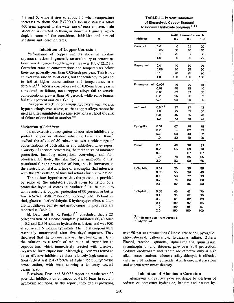
(1)Indicative data from Figure 1.(2)mlf230 m!.
TABLE 2 - Percent Inhibition
of Electrolytic Copper Exposedto Sodium Hydroxide Soiutions3( 1)
Inhibition of Aluminum CorrosionAluminum alloys have poor resistance to solutions of
sodium or potassium hydroxide, lithium and barium hy-
over 90 percent protection: Glucose, resorcinol, pyrogallol,phloroglucinol, gallocyanine, hydrazine sulfate. Others:Phenol, catechol, quinone, alpha-naphthol, quinalizarin,m-aminophenol and thiourea gave over 80% protection.Sodium rhodizonate and tannin are effective only at highalkali concentrations, whereas salicylaldehyde is effectiveonly in 2 N sodium hydroxide. Acriflavine, acetylacetoneand cupron were unsatisfactory.
1!
NaOH Concentration, N0.2
0.51.0
0
252065
705575
82800
3222
40
509590
959090
9590100
100100
40
201840
184082
878595
958992
9890
17
174225
356045
557072
7873
62
787582
8568
486282
3835
48
788355
839087
8778
858583
9065
20
255555
284058
727376
808080
8580
40
457038
627065
8283100
9285100
9597100
100100
Pyrogallol 0.010.20.51.0
B-Naphthol 0.050.10.20.51.02.0
L-Naphthol 0.010.050.10.20.5
Tannin 0.10.20.51.02.0
m-Cresol 0.5(2)1.02.04.0
Resorcinol 0.010.050.11.0
Inhibitor %
Catechol 0.010.050.11.0
Phloroglucinol0.0010.010.050.20.7
248
4.5 and 5, while it rises to about 5.5 when temperatureincreases to about 550 F (290 C). Because stainless Alloy600 areas exposed to the water are of most concern, mainattention is directed to them, as shown in Figure 2, whichdepicts some of the conditions, inhibitive and controladditions and corrosion rates.
Inhibition of Copper CorrosionPerformance of copper and its alloys in alkaline
aqueous solutions is generally unsatisfactory at concentrations over 40 percent and temperatures over 100 C (212 F).Corrosion rates at concentrations and temperatures belowthese are generally less than 0.02-inch per year. This is notan excessive rate in most cases, but the tendency to pit andto fail at higher concentrations and temperatures is adeterrent. 22 When a corrosion rate of 0.05-inch per year isconsidered as failure, most copper alloys fail at causticconcentrations greater than 50 percent, while some brassesfail at 20 percent and 24 C (75 F).
Corrosion attack in potassium hydroxide and sodium
hypocWoritelis even worse, so that copper alloys cannot beused in these uninhibited alkaline solutions without the riskof failure of one kind or another. 2 2
Mechanism of Inhibition
In an extensive investigation of corrosion inhibitors toprotect copper in alkaline solutions, Desai and Rana3studied the effect of 30 substances over a wide range ofconcentrations of both alkalies and inhibitors. They reporta variety of theories concerning the mechanism of inhibitorprotection, including adsorption, overvoltage and filmprocesses. Of these, the film theory is analogous to thatpostulated for the protection of iron, that is, formation atthe electrolyte-metal interface of a complex that interfereswith the transmission of ions and retards further oxidation.
The authors hypothesize that the protection providedby some of the inhibitors results from formation of aprotective layer of corrosion products.3 In their studieswith electrolytic copper, protection of 90 percent or betterwas achieved with resorcinol, phloroglucinol, beta-naphthol, glucose, furfuraldehyde, 8-hydroxyquinoline, sodiumdiethyl dithiocarbamate and gallocyanine. Typical data arereported in Table 2.
M. Desai and B. K. Punjani23 concluded that a 2%concentration of glucose completely inhibited 60/40 brassin 0.2 and 0.5 N sodium hydroxide solutions and was 90%effective in I N sodium hydroxide. The metal coupons wereessentially untarnished after five days' exposure. Theytheorized that the glucose removed dissolved oxygen fromthe solution as a result of reduction of cupric ion tocuprous ion, which immediately reacted with dissolved
loxygen to form cupric ions. Although glucose was found tobe an effective inhibitor at these relatively high concentrations (2%) it was less effective at higher sodium hydroxideconcentration, with brass showing a tendency towarddezincification.
Elsewhere, Desai and Shah24 report on results with 30potential inhibitors on corrosion of 63/67 brass in sodiumhydroxide solutions. In this report, they cite as providing

droxide and sodium sulfide. Ammonium and calcium
sulfides are not as corrosive.2 5 Sodium and potassiumcarbonates, along with calcium hydroxide are recorded inthe Corrosion Data Survey22 as causing corrosion at ratesover 0.05-inch per year at 10 to 30 percent concentrationsin water from 24 to 100 C.
Solutions of sodium or potassium hydroxide of lessthan 0.01 percent concentration can be inhibited bysilicates or chromates.2 6 Sodium silicates with ratios ofsilica to soda of 0.67 to 3.22 have been successful in
inhibiting sodium carbonate solutions. It has been foundnecessary to use about 6 percent as much silicate as sodiumcarbonate in the solution or about 120 mg silicon dioxidefor each 57 sq dm of aluminum surface. Similar results wereachieved with sodium fluosilicate.2 6
Sodium disilicate is used as a corrosion inhibitor in
alkaline cleaners and about 1 percent sodium metasilicateor sesquisilicate is effective in triethanolamine.
Grundberr and Kiermeier27 report that 1 : 2.5 ratiosof Na2 O:Si O2 prevented corrosion of aluminum in pH 11solutions at 80 C. For higher temperatures more silicate isrequired. The film on the aluminum is believed to benon-aggregated silicate.
Wide Interest in Aluminum Inhibitors
Largely because of the known susceptibility of aluminum to attack by caustics, there has been a wide interest inlocating inhibitors effective in reducing its corrosion inalkaline media. This interest has resulted in numerous
laboratory and application studies as reported in thetechnical literature. Among recent reports are the following:
Beta-Diketones:28 Japanese researchers conducting along series of investigations, identify as useful in pH 10.5media, compounds with large hydrophobic and electronegative groups. These substances are believed to formaluminum chelate compounds which cover the surface.
Pit Formation Mechanism: Ishida29 discussing themechanism of pit formation in alkaline waters, found thattribasic sodium phosphate or sodium silicate inhibit pittingin the 1 to 5 ppm range, while sodium carbonate in the 3 to5 ppm range accelerates it.
Naphthenic Acid Derivatives: Sodium salts of naphthenic acids, amides and products derived from neutraliza-
, tion of naphthenic acids by amines and aminoalcohols werefound by Kyazimov3o to inhibit corrosion of Russian AlloyDl6T (approximately U. S. 2017) in pH 13 aqueoussolutions. Naphthenates from "petroleum drilling water"did not inhibit corrosion. He reported the followingreaCtions, among others: Amides synthesized from naphthenic acids derived from diesel fuel are protective in 0.4 Nsodium hydroxide as well as in pH 13 solutions. Optimuminhibitor concentration ranges from 0.5 to 1.5 percent anddepends on alkali concentration. The inhibitors limit theanodic reaction.
Alkalies as InhibitorsThe practice of using alkalies to modify the character
istics of acidic solutions is widespread in industry, and is
249
effective in controlling corrosion by naphthenic acids inpetroleum refineries31 and elsewhere.
Discussing the use of alkalies as inhibitors in a coaldistillation plant, Cronau32 described plugging that tesultedfrom the addition of sodium carbonate and sodium
hydroxide to process streams. This plugging necessitateddiscontinuing the use of the alkalies although some reduction in corrosion rates was achieved.
SummaryFundamental causes of caustic attack on materials are
fairly well understood. There is less agreement on thefundamental causes for the effectiveness of inhibitors, butthis has not prevented the discovery of effective inhibitionschemes that are commonly applied in alkaline environments.
Research into the causes of reactions in the alkaline
range in aqueous and other environments is widespread andhas produced information on useful and potentially usefulinhibitors. Many of these inhibitors are being tested inlaboratories and applied in the field to add to the store ofinformation about effective inhibitors for alkaline environments. Trial and error methods have identified somematerials useful as inhibitors in alkaline solutions and
established the parameters needed to make their performance effective.
References1. D. Gilroy and J. E. O. Mayne. Inhibition of Corrosion of Iron in
Neutral and Alkaline Solutions, 2nd Europ. Symp. on Corrosion Inh., 2, p585-595 (1966).
2. H. P. Godard, W. B. Jepson, M. R. Bothwell and R. L. Kane.Corrosion of Light Metals, John WHey & Sons, Inc., New York,p3 (1967).
3. M. N. Desai and S. S. Rana. Inhibition of Corrosion of Copperin Sodium Hydroxide Solutions, 2nd Europ. Symp. on Corrosion Inh., 2, p609-647 (1966).
4. J. E. ReinoehL Natural Conditions for Caustic Cracking of aMild Steel, NACE Conference, Corrosion/72, Preprint No. 62.
5. Stress Corrosion Cracking in Alkaline Solutions. TPC-5CSubsurface Corrosion by Alkaline Solutions, OJ"osion, 7, No.9,295-302 (1951) Sept.
6. R. M. Latanision and R. W. Staehle. Stress Corrosion Crackingof Iron-Nickel-Chromium Alloys, Proc. Symp. Fund. Aspects ofStress Corrosion Cracking, NACE, Houston, Tx., p265-9(1969).
7. I. L. Wilson, P. W. Pement and R. G. Aspden. Effect of AlloyStructure, Hydroxide Concentration and Temperature on theCaustic Stress Corrosion Cracking of Austenitic Stainless Steels,NACE Conference, Corrosion/72. Preprint No. 61.
8. W. M. Huybrechts, G. VanOsch and A. Snel. PolarizationMeasurements on Iron in Alkaline Solutions at High Pressuresand High Temperatures, Proc. 4th Int. Congo Met. Cor.,Amsterdam, NACE, Houston, Tx., p501-16 (1969).
9. U. R. Evans. Metallic Corrosion, Passivity and Protection,Longmans, Green & Co., New York, p282-3 (1948).
LO. H. L. Logan. Stress Corrosion of Metals, John Wiley & Sons,Inc., New York, N. Y., p45 (1966).
11. K. Sakiyama and M. Jujimoto. Effects of Ni and NaN03 onCorrosion of Cast Iron in Concentrated Caustic Soda Solutions,/. Jap. Inst. Met, 33, No. 4, 484-8 (1969) Apr. OJr. Abst.1969, 366-29.
12. T. Oki and K. Wakamatsu. Effect of Polysulfide Sulfur onCorrosion in High Alkaline Solutions, Denki Kagaku, 37, No. 6,442-7 (1969) June, OJr. Abst. 1969,400-56.

13. E. C. Potter. Oxidation of Steel in Hot Aqueous Conditions andIts Significance in Steam Boiler Technology, Proc. 4th Int.Congo Met. Cor., Moscow, NACE, Houston, Tx., p21l-B (1966).
14. Betz Handbook of Industrial Water Conditioning. Sixth Edition, 1962, Betz Laboratories, Inc., Phila., Pa. p146.
15. R. C. Ulmer. Corrosion Study of Metals for Supercritical PowerPlants, High Purity Water Corrosion of Metals, NACE, Houston,Tx., p6B-Bl (1960).
16. A. B. Sisson. Water Chemistry at Dresden Nuclear PowerStation, Proc. NACE 25th Conf., NACE, Houston, Tx., p385-9(1969).
17. W. Stein. Chemistry at the Indian Point Nuclear Power Station,Proc. NACE 25th Conf., NACE, Houston, Tx., p390-6 (1969).
lB. J. Connally. Closed Cycle Yankee-Rowe Reactor Plant Operating Experience, NACE 25th Conf. Proc., NACE, Houston, Tx.,p397-B (1969).
19. R. H. Graves. Chemistry and Waste Management at theConnecticut Yankee Atomic Power Plant, Proc. NACE 25thConf., NACE, Houston, Tx., p399-404 (1969).
20. C. J. Hartman and C. E. Axtell. Unusual Corrosion ProblemsAssociated With a Boiling Water Reactor, Proc. NACE 25thConf., NACE, Houston, Tx., p405-B (1969).
21. D. A. Miller and P. E. C. Bryant. Corrosion and CoolantChemistry Interactions in Pressurized Water Reactors, Proc.NACE 26th Conf., NACE, Houston, Tx., p292-300 (1970).
22. Corrosion Data Survey. NACE, Houston, Tx., (1967).23. M. N. Desai and B. K. Punjani. Co"osion et Anti-Co"osion,
(French). (1971) Sept. B.
250
24. M. N. Desai and Y. C. Shah. Inhibition of Corrosion of 63/37Brass in Sodium Hydroxide Solutions, Werks. und Kor., 21,795-B (1970), Cor. Abst., p453-6 (1970).
25. F. L. LaQue and H. R. Copson. Corrosion Resistance of Metalsand Alloys, 2nd Edition, Reinhold Pub. Corp., New York, p204(1963).
26. G. G. Eldredge and J. C. Warner. Inhibitors and Passivators,Corrosion Handbook, H. H. Uhlig, editor, John Wiley & Sons,New York, p915 (1948).
27. G. Wilbrett, Kl. V. Grundberr and F. Kieirmeyer. The Behaviorof Sodium Silicate as a Corrosion Inhibitor for Aluminum inAlkaline Solutions, Werks. Und Kor., 18, 217-22 (1967), Cor.Abst., p249-96 (1967).
2B. K. Horiguchi, K Sawamura, I. Saito and Y. Hayakawa. Studieson Corrosion Inhibitors for Aluminum in Alkaline Media. IV,Beta-Diketones as Corrosion Inhibitors, J. Electrochem. Soc.Japan, 34, No. 3,162-4 (1966), Cor. Abst. 423-1 (1967).
29. S. Ishida. Some Studies on Pit Formation on Aluminum
Immersed in Waters, Proc. 3rd Int. Congo Met. Cor., Moscow,NACE Houston, Tx., 1, p 179-B5 (1966).
30. A. M. Kyazimov. Inhibitors Synthesized From NaphthenicAcids, Azerb. nett. kh-vo., No. 1, 34-8 (1968), Cor. Abst.376-B7 (1970).
31. W. A. Derungs. Naphthenic Acid Corrosion-An Old Enemy ofthe Petroleum Industry, Co"osion, 12, No. 12 617t-622t(1956) Dec.
32. R. C. Cronau. Reducing Corrosion in Coal Tar DistillationEquipment, Mat. Pro., 14, No. 12,52-56 (1965) Dec.

Applications of Inhibitorsin Miscellaneous Environments
NORMAN E. HAMNER*
Following are several short summaries of information onapplications of inhibitors in miscellaneous environments.The summaries do not include all of the miscellaneous applications but do indicate the extent to which inhibitors areemployed and show what results or lack of results can beanticipated.
Throughout these descriptions, there is repeated reference to many of the principles of inhibitor application thatare described in detail in the chapter on fundamentals. Thisdemonstrates the substantial universality of mechanisms ofinhibitor function.
INIDBITION OF CORROSION BY DEICING SALTS(l)
IntroductionWhen Pope! reported on the corrosion of telephone cablesas the result of salt used by street railways to deice switchesin their tracks, the American Committee on Electrolysishad been studying for many years the effect of underground stray currents as well as the possible influence ofsalt on telephone cables. There was little doubt that straycurrents caused the formation of caustic crusts on leadsheathed cable or that these crusts caused corrosive attack.
Although there was an apparent consensus that deicingsalt was a main cause of the caustic attack on cables,2 thework of Bruckner and Wainwright,3 among others tendedto show that the principal corrodents were, in fact, magnesium or calcium oxides and that sodium chloride's influence
was mainly as an ion exchange medium and perhaps also areducer of soil resistance. Hart4 disagreed with their conclusions, however, and attributed corrosive attack to NaCl.
While there is little doubt that extensive corrosion
damage is suffered from street deicing salts, numerous testshave apparently not produced conclusive evidence eitherthat the addition of inhibitors has given measurable benefitsor that the cost of adding the inhibitors can be justified bythe benefits observed. An NACE repore cited the fact that34 cities used salt or combinations of salt and cinders to
remove ice from streets. Per capita use was between 7 and70 lb a year.
< It is clear that sodium chloride contributes to the corrosion of aluminum bolts in highway light standards,s reinforcing steel in highway structures,6 underground pipes andcables2 and other structures. Total losses were estimated bythe NACE committee2 as Of 1950 at $100,000,000 a year.
*Staff, National Association of Corrosion Engineers, Houston, Tx.
(1)See chapter on automobile corrosion for discussion of effect ofdeicing salt on vehicles.
251
Although concentrations in telephone cable manholewaters was found to be greater than in sea water! 3 andrelatively the same winter and summer, no way has beenfound to prevent the corrosion that results. Telephonecompanies attempt to reduce attack by flushing the cableruns with fresh water, but this has produced only limitedbenefits.
There also are restrictions on some inhibitor materials
such as phosphates, because of their bad ecological effectsin runoff water. Similar problems exist with respect to urea,formamide and calcium formate, alternate deicants, mainlyrejected for cost reasons.
Table 1 lists some of the inhibitors that have been used
ill deicillg salts together with comments on their use.
TABLE 1 - Summary of DataDeicing Salt Inhibitors'
Used%$ TonEffectivenessInhibitor
WithConcentrationSaltComments
Hexametaphosphate
NaGt1.0>3NegligibleMetal powder
NaCI0.5>3NegligibleProprietary
NaCI0.5>3NegligibleDichromate
NaCI1.0>3NegligibleCarguard(2)
NaGl 4
CalciumCarbonate
NaGI
POlyphosphate- NitriteNaGI 90 percen,(1)
~anox
NaGI 55 percent
Chromates
NaGI
ChromatesCaCI2
(J )laboratory tests.(2)The Role of Salts in the Total Corrosion Environment of the Automo
bile. F. O. Wood. Proc. NACE 26th Coof., NACE, Houston, Tx.pp 106·110.

SummaryEvidence so far available indicates that the addition of
inhibitors to street deicing salts is neither economical norsignificantly beneficial. In some critical instances it may benecessary to add inhibitors, such as chromates, urea,formamide or calcium formate to deicing salts. This mightbe true with respect to aircraft runways because aircraftcannot tolerate the accelerated corrosion that salts maycause on highly stressed components with minimum excessstrength factors.
References1. R. H. Pope. Corrosion by Stray Currents, Co"osion, 10,10,324
(1954) Oct.
2. Corrosive Effect of Deicing Salts. TP-I0-Corrosion by DeicingSalts, Co"osion, 10, No. 1, 3-6 (1954) Jan.
3. W. H. Bruckner and R. M. Wainwright. Lead Cable Sheath Corrosion Under Cathodic Protection Conditions, Co"osion, 13, No.2, 143t-148t (1957) Feb.
4. M. B. Hart. Co"osion, 13, No. 6, 422t (1957) June.
5. H. P. Godard. Examination of Corroded Aluminum Surfaces toDetermine the Cause of Corrosion, Proc. NACE 25th Conf.,NACE, Houston, Tx., p253-9.
6. W. K. Boyd and A. B. Tripler, Jr. Corrosion of Reinforcing SteelBars in Concrete, Mat. Pro., 7, No. 10, 40-7 (1968) Oct.
7. Concentration of Deicing Salts in Manhole Waters. NACE T-4Don Corrosion by Deicing Salts, Co"osion, 16, No. 12, 613t-614t(1960) Dec.
ADDITIVES TO CONTROL ATTACKS BY VANADIUM PENTOXIDEAND SODIUM SULFATE
TABLE 1 - Vanadium and Sodium Content of
Some Typical Blended Residual Type Fuels
TABLE 2 - Vanadium and Sodium
Content of Some Typical No. 6 Fuels
Figure 1 shows some freezing points of additives usedagainst vanadium pentoxide.
2. Barium and calcium sulfates are ineffective because
they will not react with vanadium pent oxide to form eitherortho- or pyro-forms, but instead will give the metavanadate plus sulfate. The metavanadate is more corrosivethan either of the other two forms.4
250
40100
100
200
807010106090
200
250
300
150
200
9030
200
6020
150
Parts per MillionVanadium I SodiumSource
u.s. Refiner/I)U.S. Refiner/I)U.S. Refiner/I)U.S. Refiner/I)U.S. Refiner/1)U.S. Refiner/2)U.S. Refinery(3)U.S. Refiner/I)Middle EastFar EastFar East
Parts Der MillionFuel
VanadiumSodium
L
90200M
15040N
500900
22437p
80060
ABCDEF
G
HIJK
Sample
~1~south American crude.; United States crude.
( )United States (California) crude.
252
As shown in Tables 1 and 2,1 vanadium and sodium arefound in significant concentrations in petroleum residualfuels from all parts of the world. Of the elementsconcentrated, vanadium and sodium are considered to bemost corrosive at temperatures of 1200 F (649 C) or over.
Economics is the main reason for using residual fuels insteam generation plants, diesel engines and so-called gasturbines.
While there is no uncontested consensus, the nature ofthe attack by vanadium (as the pentoxide) and sodium isconsidered to be the result of:
1. Their ability to form a liquid at the temperaturesinvolved, and
2. The ability of this liquid to dissolve protectivecorrosion products from the metal on which it forms, thusexposing virtually clean metal continuously to attack byoxygen, and also
3. Ability of the vanadium-sui fate liquid to absorboxygen.2
Because vanadium compounds usually are found incombination with sodium and sui fur (as sodium sulfate),control of the corrosion is complicated by the fact thatadditives effective for vanadium may not be effective forsodium. The most corrosive mixture is that containingabout 15% sodium sulfate and the rest vanadium pentoxide.3
A large number of metal oxides as well as kaolin andkeiselguhr (which consist of aluminum and silicon oxidesmainly) have been used with more or less success to controlcorrosion by vanadium-sulfate eutectics. One of the problems in using them is to disperse them effectively into the
I fuel before burning to assure maximum contact betweenthe addi tives and the residual corrosives. They usually areadded as slurries (Mg and Zn acetates, for example) andproportioned into the fuel stream just before burning.
In general it has been discovered that:
1. Metal oxides (Mg, AI, Ba and Ca) are effective whenpresent in concentrations above the stoichiometric ratio. I

-
Residual fuel, laboratory test data
FIGURE 3 - Cross section through reradiating cone in aboiler attacked by vanadium pentoxide.8
3:1
3:12:1
Ratio
Barium oxide or carbonate to V mole4OrthovanadatePyrovanadate
Mg salt to V weightl,3
TABLE 4 - Application Recommendationsfor Additives to Reduce Vanadium Pentoxide Attack
1.0 Na
o
0.2 0.60.8 0.4
Mole Fraction Cone.
o1.0
o
2400
••
"0~Cl'';:;5i 1600(,)ell3l
~0 800
3200
FIGURE 1 - Calculated freezing point diagrams withvanadium pentoxide.7
Calcium oxide to V mole4OrthovanadatePyrovanadate
3:12:1
TABLE 3 - Arrangement of Inorganic Compoundsin Decreasing Order of Effectiveness
in Reducing Corrosion
Iron Base Alloy1450 F 1600 F
Nickel Base Alloy1450 F 1600 F
(I )These ratios tested against various NiCr alloys used forturbine blades.
1:1-4:110:1
2:1
Approx. WtRatio(l)
Magnesium oxideVermiculiteZinc oxide
Additive
Residual fuels for gas turbines8vs vanadium pentoxide plus 10% sodium sulfateat 700 C:5
ZincCalciumMagnesiumPhosphorus
PhosphorusZincMagnesiumCalcium
CalciumMagnesiumPhosphorusZinc
MagnesiumZincPhosphorusCalcium
FIGURE 2 - Calculated freezing point diagrams with sodiumMllfate.7
Additive RatioCompoundF
MgS04-kaolin
2/1/2MgN/(AI-Si)2060BaS04-kaolin
0.5/1/2BaN/(AI-Si)1840CaS04
2/1/0CaN /(AI-Si!2035CaS04 -kaolin
1/1/1CaN/(AI-Si)1895MgO-kaolin
1/1/2MgN/(AI-Si!1500
TABLE 5 - Selected Melting Points ofSome Additive Compounds to Reduce Attack
by Vanadium Pentoxide4
3. A high melting point (over 1500 F) complex formsamong magnesium oxide, kaolin and vanadium pentoxide.Table 3 shows some of the effective additions and the
temperatures associated with their oxide combinations withthe residuals.5
4. Precautions must be taken when using additiveswith residual oils intended for diesel engines and gasturbines. Some additives may create excessive deposits(especially on turbine blades) that may require frequent
0.8 1.0 Na0.2 0
0.40.6
Mole Fraction Concentration
800
2400
••"0ca
.g> 1600c:••(,)
~Cl••o
O.
NaS04 1.0
o
~Sodium
Sulphate
253

USE OF INHIBITORS TO CONTROL CORROSIONBY AGRICULTURAL CHEMICALS
shutdowns for cleaning. While a wide range of materials hasbeen used with more or less success in attempts to controlcorrosion of turbines (talc, crushed walnut shells, dolomite,
among others, if.1cluding some mentioned herein in othercontexts), some success has been achieved with materialsdissolved in oil and added as solids. Manganese naphthenate, rare earth and magnesium naphthenates as well aslanthanum, antimony and iron naphthenates and derivatesof calcium, sodium, manganese, cerium and neodymiumalso performed well in tests.
Occasional good results have been achieved by using asolid in addition to an oil-soluble additive.6 Turbine
capacity losses have been reduced to 3% by a mixture ofmagnesium naphthenate and kaolin as compared to 22% formagnesium naphthenate alone and 27% for kaolin alone.Some of the benefits may be the result of the abrasiveeffect of the solids,
5. Sodium sulfate appears to be responsible for oxygenabsorption. The capacity of the vanadium-sodium to absorboxygen increases sharply with sodium content up to about16%.2
6. Kaolin probably is effective against sodium becauseit liberates sulfur as S03 .4
7. Calcium soap additives in residual oil burned in asteam boiler reduced corrosion by about 60%.6
Laboratory tests have shown that kaolin inhibitssodium corrosion and reduces the attack to a rate that canbe attributed to oxidation alone. Silicon or aluminum
oxides give less protection.4 Figure 2 gives some freezingpoints of additives used against sodium sulfate. Figure 3shows cross section of a reradiating cone in a boilerattacked by vanadium pentoxide.8
Because the main data reported above are derived from
Introduction
Attack on metals and alloys by insecticides and fertilizers
ranges from negligible to disastrous. As is true also in thecase of other corrosives, inhibitors are commonly employedonly in the aqueous phases, while various other means(coatings, good housekeeping) are used with solid, particulate or gaseous materials to control corrosion attack.
Schreiber1 lists a large number of insecticides, herbicides and fungicides and describes their effects on aluminum, steel, brass, Monel and Type 302 steel as well as on anumber of nonmetals used as coatings. Liquid fertilizers(nitrogen, phosphoric acid, potash and water) caused noattack in the vapor phase on aluminum but it pitted in theaqueous phase. Fungicides (various sulfur), defoliants(magnesium chlorate) and ammonia fertilizers had variouseffects on metals ranging from nothing to catastrophicfailure as reported in his tests.
Cook and Dickinson,2 discussing attacks by insecticides, gave results of tests with DOT, chlordane and sodium
254
laboratory tests during which oxygen content is not likelyto be the same as that under combustion conditions, theconclusions are not strictly applicable in practice.
Additives are used in proportion to the volume ofresidual corrosives in the fuel, so it is necessary to knowwhat these volumes are before deciding on additive ratios.In at least one case, use is facilitated by the additive beingin an oil phase and thus much easier to proportion.!Magnesium naphthenate, ethyl silicate and calcium sulfonate produce suitable compounds on combustion.s Tables4 and 5.7
References1. A Liquid Additive to Limit Oil Ash Corrosion. R. S. Norris.
Co"osion. 13, No. 7, 123-]24 (1957) July.2. Effects of Contamination by Vanadium and Sodium Compounds
on the Air-Corrosion of Stainless Steel. G. W. Cunningham andA. deS. Brasunas. Corrosion, 12, No. 8, 389t-405t (1956)August.
3. The Present Status of the Oil Ash Corrosion Problem, NACET-5B-3 Report. Corrosion, 14, No. 8, 369t-372t (1958) August.
4. Reaction Between Fuel Ash Components and Additive Combinations. W. D. Niles and C. W. Siegmund. Mechanism of FuelImpurities. H. R. Johnson and D. 1. Littler. editors. Butterworth's. 1963, pp. 332-346.
5. Corrosion Aspects of the Vanadium Problem in Gas Turbines. S.H. Frederick and T. F. Eden. Corrosion, 11, No. ]. ] 9t-33t(1955) January.
6. Corrosion and Deposits in Boilers and Gas Turbines. ASMEResearch Committee on Corrosion and Deposits from Combustion Gases. 1959. ASME, 29 W. 39th St.. New York, N. Y.. p.161.
7. A Thermochemical Study of Some Additives to Fuel AshCorrosion. W. E. Young and A. E. Hershey. Corrosion, 13, No.11. 725t-732t (1957) November. Figures 9 and ]0.
8. Refractory Coatings to Prevent Vanadium Corrosion. Philip D.Cady. Materials Protection, 2, No. ] 0,28-34 (] 963) October.
arsenite. Aluminum, carbon and stainless steels. copper,magnesium, brass and galvanized steel were attacked by oneor more of the corrosives, 2-4-0 inhibited corrosion of all
metals tested, while chlordane and sodium arsenite in waterand DOT in salt water were the most corrosive combinations tested.
Inhibition of Weed Killer SolutionsAlquist and Wasc03 used sodium chromate, sodium
hydroxide, mineral oil and a proprietary oil in inhibitortests involving water soluble salts of trichloroacetic acid(TCA), a weed killer. In a 50 percent concentration ofTCAin water, sodium chromate at 0.7 percent (Na2Cr207) reduced corrosion of aluminum, carbon steel, 85-15 brass,70-30 brass and copper (as well as tinned and galvanizedsteel) by 80 percent or more. Types 304, 316, 321 and 347steel were unaffected by the solution.
As a practical result of the tests, they shipped TCA intank cars, protecting the vapor space by putting 55 gallonsof a proprietary petroleum oil in the car before filling it
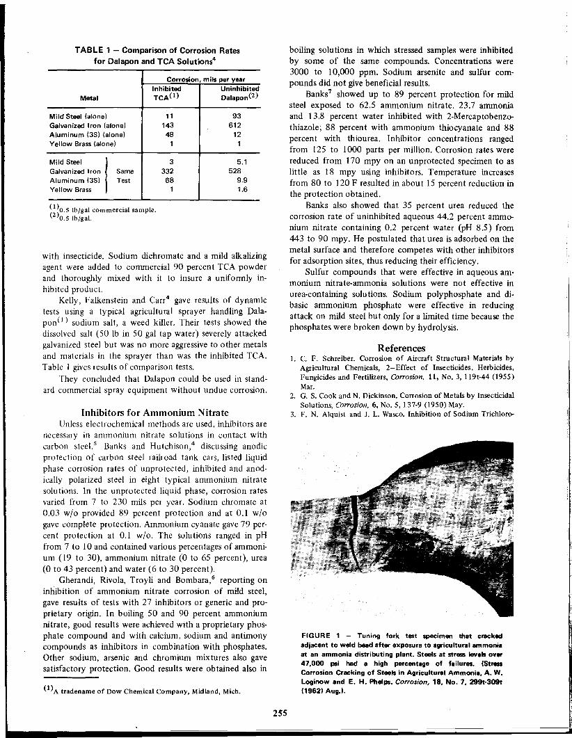
(l)A tradename of Dow Chemical Company, Midland, Mich.
TABLE 1 - Comparison of Corrosion Ratesfor Dalapon and TCA Solutions4
g~o.sIb/gal commercial sample.o.S Ib/gal.
References1. C. F. Schreiber. Corrosion of Aircraft Structural Materials by
Agricultural Chemicals, 2-Effect of Insecticides, Herbicides,Fungicides and Fertilizers, Co"osion. 11, No. 3, 119t-44 (1955)Mar.
2. G. S. Cook and N. Dickinson. Corrosion of Metals by InsecticidalSolutions, Co"osion, 6, No. 5, 137-9 (1950) May.
3. F. N. Alquist and J. L. Wasco. Inhibition of Sodium Trichloro-
FIGURE 1 - Tuning fork test specimen that crackedadjacent to weld beadafter exposure to agricultural ammoniaat an ammonia distributing plant. Steels at stress levelsover47.000 psi had a high percentage of failures. (StressCorrosion Cracking of Steels in Agricultural Ammonia, A. W.Loginow and E. H. Phelps. Corrosion. 18. No. 7. 299t-309t(1962) Aug.).
boiling solutions in which stressed samples were inhibitedby some of the same compounds. Concentrations were3000 to 10,000 ppm. Sodium arsenite and sulfur compounds did not give beneficial results.
Banks 7 showed up to 89 percent protection for mildsteel exposed to 62.5 ammonium nitrate. 23.7 ammoniaand 13.8 percent water inhibited with 2-Mercaptobenzothiazole; 88 percent with ammonium thiocyanate and 88percent with thiourea. Inhibitor concentrations rangedfrom 125 to 1000 parts per million. Corrosion rates werereduced from 170 mpy on an unprotected specimen to aslittle as 18 mpy using inhibitors. Temperature increasesfrom 80 to 120 F resulted in about 15 percent reduction inthe protection obtained.
Banks also showed that 35 percent urea reduced thecorrosion rate of uninhibited aqueous 44.2 percent ammonium nitrate containing 0.2 percent water (PH 8.5) from443 to 90 mpy. He postulated that urea is adsorbed on themetal surface and therefore competes with other inhibitorsfor adsorption sites, thus reducing their efficiency.
Sulfur compounds that were effective in aqueous ammonium nitrate-ammonia solutions were not effective in
urea-containing solutions. Sodium polyphosphate and dibasic ammonium phosphate were effective in reducingattack on mild steel but only for a limited time because thephosphates were broken down by hydrolysis.
11 93
143
612
48
12
1
1
3
5.1
332
528
68
9.9
1
1.6
Corrosion, mils per yearInhibited UninhibitedTCA(l) Dalapon(2)Metal
Mild Steel (alone)Galvanized Iron (alone)Aluminum (3S) (alone)Yellow Brass(alone)
Mild Steel
GalvanizedIron' SameAluminum (3S) l TestYellow Brass
with insecticide. Sodium dichromate and a mild alkalizingagent were added to commercial 90 percent TCA powderand thoroughly mixed with it to insure a uniformly inhibited product.
Kelly, Falkenstein and Carr4 gave results of dynamictests using a typical agricultural spray er handling DalaponO) sodium salt, a weed killer. Their tests showed thedissolved salt (50 Ib in 50 gal tap water) severely attackedgalvanized steel but was no more aggressive to other metalsand materials in the sprayer than was the inhibited TCA.Table I gives results of comparison tests.
They concluded that Dalapon could be used in standard commercial spray equipment without undue corrosion.
Inhibitors for Ammonium NitrateUnless electrochemical methods are used, inhibitors are
necessary in ammonium nitrate solutions in contact withcarbon steel.s Banks and Hutchison,4 discussing anodicprotection of carbon steel railroad tank cars, listed liquidphase corrosion rates of unprotected, inhibited and anodically polarized steel in eight typical ammonium nitratesolutions. In the unprotected liquid phase, corrosion ratesvaried from 7 to 230 mils per year. Sodium chromate at0.03 wlo provided 89 percent protection and at 0.1 wlogave complete protection. Ammonium cyanate gave 79 percent protection at 0.1 w/o. The solutions ranged in pHfrom 7 to 10 and contained various percentages of ammonium (19 to 30), ammonium nitrate (0 to 65 percent), urea(0 to 43 percent) and water (6 to 30 percent).
Gherandi, Rivola, Troyli and Bombara,6 reporting oninhibition of ammonium nitrate corrosion of mild steel,
gave results of tests with 27 inhibitors or generic and proprietary origin. In boiling 50 and 90 percent ammoniumnitrate, good results were achieved with a proprietary phosphate compound and with calcium, sodium and antimonycompounds as inhibitors in combination with phosphates.Other sodium, arsenic and chromium mixtures also gavesatisfactory protection. Good results were obtained also in
255

acetate Weed Killer Solutions, Corrosion, 8, No. 12, 410-12(1952) Dec.
4. J. A. Kelly, W. J. Falkenstein and J. P. Carr. The Determinationof the Effect of a New Grass Killer on Application Equipment,Corrosion, 12, No. 2, 79t-83t (1956) Feb.
5. W. P. Banks and M. Hutchison. Anodic Protection of Carbon
Steel Rail Tank Cars Transporting Nitrogen Fertilizer Solutions,Proc. NACE 24th Conf., NACE, Houston, Tx., p7-15 (1968).
6. D. Gherandi, L. Rivola, M. Troyli and G. Bombara. Inhibition ofAmmonium Nitrate Corrosion of Mild Steel, Proc. 2nd Int. Congress on Met. Cor., Houston, Tx., NACE, Houston, Tx., p605-11(1963).
7. W. P. Banks. Inhibiting Mild Steel in Nitrogen Fertilizers, Mat.Pro., 7, No. 3, 35-8 (1968) Mar.
INHIBITION OF CORROSION IN DOMESTIC FUEL OIL TANKS
HEXA VALENT CHROMIUM CONTROLSCOAL SLURRY PIPELINE CORROSION
Alkaline sodium nitrite at a concentration of 0.25 percentgave complete protection from rusting of test specimensexposed under conditions simulating those in domestic fueloil tanks. The tests, conducted by Wieland and Treseder Iinvolved a number of candidate inhibitors, results which are
given in Figure 1.Their investigation into the mechanisms of corrosion of
tanks storing fuel oil for domestic heating systems showedtwo main factors contributing to the accelerated attack ontanks, which attack sometimes resulted in perforations.These included the unfavorable galvanic relationshipbetween a large area of mill scale inside the tank and smallperforations of coatings and/or mill scale that exposed thesubstrate metal. The other factor was accumulation of small
quantities of water, usually containing chlorides, at lowpoints in the tanks where holidays in the coatings or millscale existed.
Powdered sodium nitrite and alkaline buffer were intro
duced into fuel tanks in 4 ounce doses just prior to an oildelivery. An extensive field test program using this technique resulted in an 87 percent reduction in tank leaks thefollowing year, indicating the inhibitor was effective instopping corrosion of many tanks badly corroded at thetime the inhibitor was added. Subsequent analyses of fluidsfrom tank bottoms indicated that effective concentrations
of inhibitor persisted for several years after a treatment.Over 50,000 tanks were treated. I
After 5 years' operation there was no indication of seriousmetal corrosion anywhere in the 108-mile coal slurry pipeline between Cadiz, Ohio and the Eastlake plant of Cleveland on the shore of Lake Erie.l Over 7 million tons of coal
ih a slurry of coal and water were pumped through the linefrom 1957 through 1962. I Corrosion protection wasachieved through the addition to the slurry of hexavalentchromium at concentrations up to 35 parts per million. Theslurry consisted of water and coal ground to a modified 14mesh by 0 grind at 50 percent concentration.
Tests conducted prior to and during the operation ofthe line showed that effective corrosion control was
256
NaN01
NaNO, Plus Boraxa)
NaNO, Plus Na,COsa)
Na,CrO.
Na,CrO. Plus Boraxa)
Na,CO)
Borax
o 0.5 1.0 l.OConcentration g/lOO ml
Rust _ Occasional Rust lIIDNo Rustc:::J
FIGURE 1 - Effect of water soluble inhibitors on the corrosion of steel by fuel oil plus sea water. a. Ratio 3:1. Listedaccording to sodium nitrite or sodium chromate concentration.l
Reference1. R. Wieland and R. S. Treseder. Internal Corrosion in Domestic
Fuel Oil Tanks, Corrosion, 10, No. 11,401-6 (1954) Nov.
achieved when concentrations of sodium chromate were
made at a rate of 20 ppm at the Cadiz end where the slurrywas pumped into the pipeline. This resulted in a 14 ppmresidual in the line just after the initial injection. Concentration of inhibitor was found to drop to zero after about 60miles of travel and design cost of 14 cents per ton of coalfor inhibitors was found to be too high. Experience withthe line resulted in abandoning the introduction of inhibition at two points downstream from the origin of the pipeline (included in the original inhibition program) and stopping the use of hexametaphosphates which had been addedinitially under the assumption it would be required to con-

TABLE 1 - Oxidative Substance(s) TABLE 2 - laboratory Data Versus Full Scale Test Resultsin Coal Slurry Filtrates( 1)
of Three Inhibitive CompoundsPosition
Coal SlurryOxidative
(miles down IMils Per Year
TreatmentFactor(2)
InhibitorppmlinelPipelineLaboratory
"]
None I0 I114I1051.8 Nitrogen Flush
1.7 1.7Na2S03 } I133
1.3Hexametaphosphate45I0 I54I50
2.5 Cr +6 } I17
Air Flush4.1Hexametaphosphate 48I0 I2.2I2.4
8.5}
Cr+6 340 1.01.0Oxygen Flush
3.7 5.6Hexametaphosphate}9030 1.21.1
4.7602.91.4
(1)40% coal slurry (tap water) at 70 FCr +6
200 0.81.9(21 C). (2)ln I hr filtrate (as equivalent ppm Cr +6
301.42.4
by titration).
603.82.8108
3.52.8
trol pitting associated with possible low chromium concentrations. Experience also showed negligible corrosion in thedownstream areas of the line which contained slurry withlittle or no chromium. The final inhibitor cost was 1.4 centsa ton.
Other Methods TestedBecause it was evident that the major corrosion hazard
was from oxygen dissolved in the slurry when it was introduced into the pipeline, tests were made also with sodiumsulfite to determine the effect of an oxygen scavenger.2
Table 1,2 indicates the significance of oxidative substancesin increasing the corrosivity of a steel-slurry system. Table22 gives lab ora tory and full scale test results comparingsodium chromate-hex am eta phosphate and sodium sulfatehexametaphosphate additions to the line. The corrosionrate dropped from an initial 30 to 300 mils per year to 1 to20 mpy when dissolved oxygen concentration was reducedto 0.5 ppm.
If chromium disappears early in that portion of thepipe close to where oxygen en ters it, a large increase incorrosivity results, whereas if it disappears early in the postoxygen zone, a smaller peak of residual corrosion occurs.2
Temperature Is ImportantBomberger2 showed that the net result of the relation
ships between temperature, oxygen and inhibitors was thatlow temperature were more corrosive than high temperature slurries. He also showed that residual corrosion (thatwhich occurred downstream from the points at whichchromium concentration was reduced essentially to zero)
wfls caused by inorganic ions, mainly chlorides and products of the coal-oxygen reaction.
FIGURE 1 - Weighable test specimen installed directly incoal slurry pipeline by means of coupling. I
Figure 1 shows the method used by Swan, Bombergerand Barthauer to determine the actual corrosion rate of the
pipeline. Their experience indicated that typical weight losson the 25 to 50 Ib test specimens was 10 to 50 grams or lessthan 3 mils a year.
References1. J. D. Swan, D. R. Bomberger and G. L. Barthauer. Corrosion
Control Achieved on Coal Slurry Pipeline, Mat. Pro.• 2, No. 9,26-34 (1963) Sept.
2. D. R. Bomberger. Laboratory Test Shows Hexavalent ChromiumReduces Corrosion in a Coal-Water Slurry Pipeline, Mat. Pro.. 4,No. I, 43-9 (1965) Jan.
INHIBITION OF HOT CHLORIDE DYE BATHS
Addition of 500 ppm sodium nitrate or sodium chromateto dye bath and dye vat scouring solutions before theaddition of 2% rock salt to the 180 F dye substantially
257
reduced corrosion of cast 18-8 stainless steel dye vat
equipment. Severe attack had occurred because of defectivewelds which permitted the salt to penetrate fissures and

INHIBITION OF REFRIGERATION BRINES
INHIBITION OF YAL YE PACKING MATERIAL
TABLE 1 -Inhibition of Refrigeration Brines(I)
Procedure
Plus sodium
hydroxide toconvert toneutral chromate
100
Concentration
Ib/1000 cu ftInhibitor
SodiumDichromate
Nael Cone. ppm Grams(%)
InitialpHConsumed(2)
2.5
1277.50.209
2.5
2557.70.142
2.5
3807.80.145
2.5
5107.90.112
Brine Type
Ca plus Mg Same200SameChloride
NaCI
Same200Same
NaCI
Disodium100Keep brine neutralPhosphate
or slightly acidwith HCI
(1)Table LII, Ref. 1.
Ca Chloride
TABLE 2 - 15-Day Consumption of Chromatein Brine Solutions by 1020 Steel(l)
(l)Figure 8, Ref. 2.(2)Solutions adjusted daily.
material.l Type 416 stainless steel, when exposed toasbestos packing that had been soaked in the chromates
References1. Metallic Corrosion, Passivity, and Protection. U. R. Evans. 1948.
Longmans, Green & Co., N. Y., p. 558.2. Inhibiting Corrosion of Steel, Aiuminum and Magnesium Inter
mittently Exposed to Brines. G. E. Best and John W. McGrew.Co"osion, 12, No. 6, 286t-292t (1956) June.
3. Corrosion Causes and Prevention. F. N. Speller. 1951. McGrawHill Book Co., New York, N. Y., p. 522.
4. Filiform Corrosion Products on Iron Immersed in Brine. P. F.Thompson and K. F. Lorking. Corrosion, 11, No. 7, 309t-31lt(1955) July.
Reference1. Severe Pitting of Stainless (18-8) Steel in Hot Chloride Dye
Baths. F. N. Speller. Corrosion, 11, No. 7, 303t (1955) July.
258
Zinc and sodium chromate effected marked improvementin reducing valve stem corrosion when added to packing
cavities. Stress corrosion cracks and carbide precipitationoccurred in the weld zones.
The inhibitor apparently built up a protective layer onthe metal which survived the chloride attack during the last20 minutes of the dyeing cycle.
Brines used in systems for cooling food storage andprocessing and for production of commercial ice usually aresolutions of calcium chloride or magnesium chloride andoccasionally sodium chloride. Rust formed by Mg and Cachloride is normally tenaciousl and may cause little rustwithout an inhibitor. However, in stronger solutions,inhibitors are useful in protecting galvanized steel anduncoated steel that comes in contact with the solution,
often for the urpose of preventing staining by rust.Sodium dichromate, with alkali additions to bring pH
just above 8.5 proved successful in producing a dense,adherent rust. Table 1 gives recommendations of theAmerican Society of Refrigerating Engineers. Where solutions come into contact with human skin, Speller recommends using sodium phosphate.2
Table 2 gives data from tests using sodium chromate inbrine solutions.
In other tests, aerated sodium chloride brine's attackon 1020 steel was drastically reduced by addition of 1%sodium chromate based on dry weight of salt. Chlorideconcentrations from 10 to 25% were effectively inhibited
by this treaqnent.2 Similar results were obtained in 5%sodium chloride in which aluminum was effectivelyinhibited at concentrations from 0.5 to 2.0%. There was
little improvement after the 0.5% concentration wasreached. Some aluminum alloys are not attacked by brine.
Magnesium in 10% calcium chloride and 25% sodiumchloride exhibited similar behavior at about the same rangeof concentrations and degrees of protection.2
Speller3 warns about the necessity of maintainingadequate concentrations of chromate because of the tendency of surfaces depleted of the inhibitor to corrode ataccelerated rates. Although solubility of oxygen in brinesdiminishes as concentration increases (Ref. 3, page 186),Thompson and Lorking3 warn of possible filiform corrosion on bare and coated iron surfaces immersed in brine.
The mechanism favored by the authors describes formation
of filiform pustules at cracks or pits in the metal surfaceinto which the dichromate cannot readily diffuse. Chromate ions participate in the growth of the filiformeorrosion.

corroded much less than when exposed under the sameconditions to packing without the chromates.
Reference1. Corrosion by Valve Packing. L. M. Rasmussen. Corrosion, 11,
No. 4, 155t-160t (1955) April.
M. E. Campbell. Solid Lubricants-A Survey, NASASP-5059 (01), 1972. Supt. Doc., U. S. Gov't Ptg. 0.,
Washington, D. C. 20402. Per copy 75 cents. p68, 69Solid lubricating materials used in corrosive atmospheresmay require the addition of inhibitors. An example is theuse of metal chromates in molybdenum sulfide-graphitebismuth-aluminum phosphate (MLF-9) lubricants. Lubricant fIlms for aluminum surfaces including molybdenumsulfide and graphite and fluorocarbons were tested in a saltfog cabinet. Molybdenum sulfide and graphite films produced corrosion in one formulation but not in others.
INHIBITORS FOR USE ON REINFORCING STEELIN CONCRETE
FIGURE 1 - Anodic polarization curves showing passivating
effect of 4% NaN02 in saturated Ca(OH)2 solutions contain
ing varying amounts of NaCI.4
3624
Months12
4
:~
3z E:Jii
20 enECl>
uk
I0
FIGURE 2 - Change with time of sodium nitrite in concrete.1-3%. 2-3% sodium nitrite + 3% calcium chloride. 3-2%sodium nitrite. 4-2% sodium nitrite + 2% calcium chloride.
5-1% sodium nitrite. S
chloride concentrations are high. Solubility must be suchthat effective quantities must be present at the corrodingsurfaces while not so good that it would be leached out ofthe mass of concrete.
Much additional work would be required beforeinhibition of reinforcing steel corrosion can be consideredpractical.2 However, beneficial results of adding chromateto fresh concrete have been reported.3
Sodium nitrite also has been tested in connection with
studies on prestressed steel reinforcement.4 These studiesshowed that when unstressed steel wires were exposed inoxygen gradient cells to saturated calcium hydroxidesolutions containing 3.5% sodium chloride that corrosionwas halted when 8% nitrite was added. In simulated
concrete environments, sodium nitrite was effective onlywhen added in amounts greater than 2% (Figure 1).
Results of a 3-year test involving the addition ofsodium nitrite and nitrate to concrete showed (Figure 2)that sodium nitrite decreased by half while sodium nitratewas still presentS at the end of the test.
Boyd and Tripler6 investigated the effect of inhibitorson corrosion of reinforcing steel in concrete by sodiumchloride solutions simulating street deicing salts runoff.Their laboratory tests sought to approximate the conditionssurrounding steel reinforcing in concrete using both sodium
100010010
Milliamperes
1.0
1.0%0.3%0.4%
0.5%
0.1
......-
While application of anodic metal coatings! to steelreinforcing in concrete is reported to be helpful inextending the life of reinforced concrete structures, it isprobable that neither anodic nor cathodic inhibitors can beused successfully to protect the steel. According to studiesof reinforced concrete structures attacked by corrosives,especially in sea marine environments, reinforcing steelcorrosion is caused by concrete porosity or insufficientthickness or both.
Factors operating against probable success of cathodicinhibitors include precipitation of hydroxides of suchinhibitors as calcium carbonate, aluminum or magnesium
hydroxide by alkaline cement substances and their dispersion in the concrete mass rather than concentration atthe concrete-steel interface.2 Anodic inhibitors, such as
alkalis, phosphates and chromates contain anions whicheither form sparingly soluble iron salts or form gamma ironoxide fIlms on the steel surface, thus preventing ferrousions from passing through and into solution at the anode.However, insufficient concentration of anodic inhibitorswould result in accelerated attack. They also would bedistributed throughout the concrete mass so, if enough wasused to produce the proper concentration at the anodes,properties of the concrete might be damaged. Also, if usedas coatings on the steel, they might reduce its bond to theconcrete.
Because the quantity of inhibitor must be proportionalto chloride concentration, economics may be poor where
500wU~ ,0E
-500
o
1000
1500
259

TABLE 1 - Effect of Inhibitors on Reinforcing SteelExposed to Sodium and Calcium Chloride Solutions.6
(1 )Scaled electrode corrodes.
(2)Calgon is a tradename belonging to Calgon Corp., Pittsburgh,Pa.
1. Calcium chloride 10% solution.
2. One electrode bare, one with mill scale; both aerated.
3. Bare anode corrodes, except as noted otherwise.4. Cathode-to-anode area ratio 1: 1.
5. Scaled electrode corrodes.
References1. Corrosion of Steel and Galvanized Steel in Concrete. Israel
Cornet and Boris Bresler. Materials Protection, 6, No. 4, 69-72
(1966) April.
2. Corrosion of Reinforcing Steel in Concrete in Marine Atmos
pheres. D. A. Lewis and W. J. Copenhagen. Corrosion, 14, No. 7,382t-388t (1959) July.
3. Reactivity of Zinc and Aluminum in Fresh Concrete. I. Gukild,
R. Husevag, and A. Markestag. 5th Scand. Corrosion Cong.,Copenhagen, 1969.
4. Studies of Electrochemical Corrosion and Brittle Fracture
Susceptibility of Prestressed Steel in Relation to Prestressed
Concrete Bridges. T. Klodt. Proc. NACE 25th Conf., 1969, pp.78-87.
5. Problems Relating to the Corrosion of Reinforcing Rods in
Concrete. Ivan Medgyesi. Proc. 4th Int. Congo Metl. Cor., NACE,Houston, Texas, 1972, p. 593.
6. W. K. Boyd and A. B. Tripler, Jr. Corrosion of Reinforcing Steel
Bars in Concrete, Mat. Pro" 7, No. 10, 40-7 (1968) Oct.
and calcium chloride solutions. Table 1 summarizes some of
their findings when test anodes consisted of segments ofsteel reinforcing bars, one of which was bare while theother had mill scale on its surface. Both anodes had accessto air.
These tests showed chromates, sodium phosphate andsodium metasilicate gave good results as determined bypotential measurements. Sodium nitrite caused a reversal ofpolarity for unknown reasons.
260
31.2
0.6
3.72.82.81.1
2.2
2.23.6
2.8
2.2
2.3
0.82.6
mpy
43178
5340401532
32
51 (1)4032
33(1)1237
Corrosion
Current,
J.1a/in2
12
0.50.5
0.5
1
1 millSat'd.111
0.4
11
Concen.
g/l
None
NazCr04 . 4HzO
Conditions:
Inhibitor
Ca3(P04)Z
Ca3(P04)Z
Na3P04' 12HzO
Calgon (NaP03n)(Z)
H3P04Ca(OH)z
NaNOzSodium benzoate
Ca(N03)Z . 4HzO
NaNOzSodium metasilicate
NazB407' 10HzO

SUBJECT INDEXA
ABMA steam purity limits, 199Abrasion, petroleum wells, in, 62Accelerated tests-See Tests LaboratoryAcetylenic alcohols vs acids, 158, 166Acidity, potable water, conc. in, 116
ACIDS
Abietic derivatives, 83Acetic, oxalic + citric, cleaning with,
156Acetic structure, 21Acetylenic alcohols vs, 158, 166Acrylic, structure, 21Aldehyde-amine condensation
products vs, 158Aliphatic amines vs, 158Alkali neutralization vs, 249Allenic alcohols vs, 158Aluminum vs, 162Amines for Al exposed to, 241Amino phenol derivatives vs, 158Analines vs, 158Arsenic vs, 158Aryl and alkyl sulfoxides, 158Bacteria, produced by, 232Boilers, weak, infl. on, 202Boiling, inhibitors for, 163Boric in nuclear primary boilers, 247Butyric vs caustic embrittlement, 212Carbonic in water flood, 77Chlorinated amines vs, 158Citric in boilers, 156Citric, inhibitors for, 161Cleaning, industrial, 156, 165Copper vs, 161, 162Cyano-ethylated amines, 158Cyclic and heterocyclic ketoamines vs,
158
Dibenzyl sulfoxides vs, 158Diffusion phenomena in, 167Dodecylpyridinium xanthates, vs, 158Ethylene oxide adducts of abietyl
amine vs, 158Fatty, napthenic in petr. ref., 44Feeding mechanism for cooling water
additions of, 129Ferrous metals vs, 156Formic in auto cooling systems, 180Fume tests of coatings, 222Furfural vs, 158Galvanic couples during cleaning with,
157
Gases, explosive, generated duringcleaning, 157
Gases in petro. drilling, 108Gas, removal from, 50Halides vs, 161Halogenated aromatics vs, 158Heat exchanger cleaning with, 157Hydrochloric vs AI, 242
" in 400 C boilers, 199" vs carbon steel, 17" vs cast iron, 157" cleaning with, 156
A
ACIDS (Cont'd.)
Hydrochloric vs copper, 157" 3,5-diamino-benzoic acid vs, 20" dodecyl benzyl aromatic amme
quaternaries vs, 18" immersion tests, 166"inhibitor for, 161"vs iron salts, 161" in petro. ref., 44" in petro. wells, 157, 164" pickling steel with, 18" vs stainless steel, 157"vs Ti, 163"velocity effect, 169
Hydrocyanic in petro. ref., 44Hydrofluoric vs, 242
" inhibitors for, 161" use in oil wells, 157
Hydroxyacetic + formic + citric,cleaning with, 156
Influence of, 13Inhibitor concentration effects, 165Lead acetate vs, 157Lead ion, infl., 164Lead nitrate vs, 157Metal salts, infl. of, 164Mine drainage in potable water, 115Naphthenic, 13, 49Neutralization in petr. ref., 44Nitric, inhibitors for, 161Nitric vs Ti, 163Nitrobenzoic, vapor phase inh. for
nonferrous metals vs, 225Nickel alloys vs, 163Oleic, in steam condensate, 214Olefinic polymers vs, 158Onium ions vs, 158Organic phosphorus compounds vs, 158Organic silicon compounds vs, 158Organic sulfides vs, 158Organic thiocyanates vs, 158Oxalic, auto engine cooling systems
cleaned with, 175Oxalic, inh. vs boiling, 163Petro drilling fluid contamination by,
gas, 107Petroleum refinery cleaning with, 165Petro wells, API-NACE Standard on
cleaning with, 69Petro wells, cleaning with, 69Phosphonic acids vs, 158Pickling, 156Piperidines & other N-ring compounds,
158
Piperidines, polymerized 4-hydroxy vs,150
Poison gases, during cleaning with, 157Polyacrylic vs deposits in cooling wilter,
130
Polymethylene imines vs, 158Poly thionic vs hydro-desulfurizers, 52
1
A
ACIDS (Cont'd.)
Propargyl benzylamines vs, 158P-2-propynyl morpholine, 158Pyridines vs, 158Pyrillium salts vs, 158Quinolines vs, 158Quniolinols vs, 158Stannous chlorides vs, 157Stearyl amines vs, 158Sulfamic, inhibitors for, 161&1lfamic + zinc + orthophosphate in
potable water, 124Sulfonated irnidazolines vs, 158Sulfonic acids vs, 158Sulfonium compounds vs, 158Sulfoximines vs, 158Sulfuric, in cooling water, 128Sulfuric, in desalination, 149Sulfuric, inhibitors for, 161Sulfuric vs iron salts, 161Sulfuric, velocity effect, 169Synergism, 166Tantalum vs, 163Tartaric for AI in antifreeze, 241Temperature influence, 163Test loop to evaluate inhibitors for, 170Tests, neutralization of coatings, 222Thiazoles, thiazines, propylene oxide
adducts of thioureas, vs, 158Thiomorpholine, pheno-thiazine and
derivatives vs, 158Thioureas vs, 158Triethyl (0,0,0) seleno phosphate vs,
158
Turbulence influence, 167Time, infl. on inhibited, 164Titanium vs, 163Velocity effects, 167Vinyl pyridine polymers vs, 158Water floods, amines vs, 79
••gas venting, 81" inhibitors vs, 80" neutralization in, 78
Xanthates vs, 158Zinc vs, 162Zirconium vs, 163
Acridine structure, 24Acridine, inh. for AI, 162,243Acrolein, bactericides, 238Acrolein in cooling water, 129di-Acrylated polyamines as boiler antifoams, 209Admiralty (CDA 442) in cooling water, 131Adsorption, calculations, 166Adsorption isotherms, 17Adsorption mechanism, 12Aerobic bacteria, 231Agar-agar for AI, 241Agricultural chemicals, inhibitors for, 254
AIRCRAFT
Coatings to protect, 193

A
AIRCRAFT (Cont'd.)
Engines, VPI for, 226Fuel, MIL test for inhibitors of, 91Fuel, rust test, 93
ALCOHOLAuto radiator in, 173Amides in steam boilers, 215Anhydrous, water for Al in, 243Water floods in, 79
Aldehydes vs acids, 158Algae in cooling water, 129Alginates as dispersants in boilers, 208Aliphatic amines vs acids, 158Alizarin in coatings, 194
ALKALISAcids, neutralization by, 249Bichromate vs nonferrous metal staining
by, 226Borates for AI, vs, 243Carbonates, lactates, acetates or
borates, for AI, in, 243Chromates for Al vs, 243Cables, telephone attacked by, 251Copper alloys vs, 248Metal nitrates for AI, in, 243Petro. drilling fluids, use in, 107, 108Phosphates for Al in, 243Silicates for Al in, 243&>dium salts, naphthenic acids for Al
in, 249Tribasic sod. phos. vs Al pitting in, 249
Alkaline cleaners, sodium disilicate as Alinh. in, 249
Alk aline arsenite-arsenate vs hydrogensulfide, 51
Alkaline earth sulfonates, 19Alkalinity range for low pressure boilers,
210
Alkalinity, potable water, 116Alkalinity, auto cooling system, 35Alkenyl succinic acid structure, 21Alkyd coatings, 192Alkyl chain length, infl. of, 214n-Alkyl quaternary ammonium, 16Alkyl benzyl dimethyl-ammonium chloride
in coatings, 193Allenic a1cohols vs acids, 158Allylamine structure, 22Allylthiourea as steel VPI, 226Allylthiourea structure, 26Alox 425 for petr. wells, 70Alum, boiler deposits vs, 197Alum, treatment of sewage effluent, 130Alumina, activated, dehydration of products
, pipelines, 90
ALUMINUM
Acids vs, 162Agar-agar for, 241Amides for, 249Amines vs acids contacting, 241Antifreeze solutions, inh. in, 241Alkalis, inh. for, 248, 249
A
ALUMINUM (Cont'd.)
Auto engines, inhibited in, 174, 175Bacterial attack on, 232Boilers, deposits in, 210Brine, inhibited in, 258Borates in ethylene glycol vs, 179Butylamines for, 242Cavitation, phosphates vs pumps in auto
cooling systems, 180, 181Chloride vs deicing salts, 183Coatings for, 192Copper vs, 115, 132Desalination, use in, 151Glycol water, protection in, 178Heat exchanger tubing, 132Hydroxide, inh. for reinforcing steel in
concrete, 259Inhibitors, characteristics of, 178, 240,
241Mechanism of corrosion, 241Nickel chromates for, 241Oil emulsions vs antifreeze sol., 241Oils with adsorption inh. for, 245Oxides vs vanadium pentoxide attack,
252
Pipelines for crude petroleum, 95Salt water in, 154Sodium chromate for, 242Static vs dynamic rates in sea water,
250 F, 152TCA, Dalapon vs, 255VPI for, 225, 226, 227Water cooling, dichromate zinc
protective in, 138Water cooling, polyphosphates in, 136
Ambiodic function, 14Amchem,168American Boiler Manufacturers' Assoc.
Standards for steam purity, 199American Petro. Inst. gravities, 45.4 to 76.6
degrees, 92
AMERICAN SOCIETY FORTESTING and MATERIALS
Au to engine cooling system testmethod, 176
Coupon designation, D-665-54, 92Gum test, 91Inhibitor test methods, 40Laboratory tests, 34Oxygen stability test, 91Pump cavitation test, 181Turbine oil test, D-665-54, 93Water separometer index, [WSIM] test,
91
Amides in steam condensate, 214Amides for petro. wells, 69
AMINE
Ethylene oxide antifoams for boilers,209
Nitrite, vapor phase inhibitors, 224Oxygenated petroleum acid vs oxygen,
87
Water solutions, corrosion in salt, 149
2
A
AMINESBacterial attack, vs, 234Boilers in, 204, 215Carbon dioxide in boilers vs, 215Cyanides in petro. ref., vs, 49Packer fluids, used in oil, IIIPetro. drilling, in, 108, 109Petro. ref., in, 45Water floods, in, 80-82
Aminoazophenylene, 16Aminobenzoates, VPI, 206Aminobenzoic acid in coatings, 194Aminoethylethanolamine structure, 23Aminoethylene phosphonate-zinc sulfate for
water floods, 76Aminomethylene phosphonates + Zn vs
oxygen in water floods, 86Aminophenol (M&P) structure, 24Aminophenol in alkalis vs Cu alloys, 248Aminophenol derivatives vs acids, 158
AMMONIABoilers in, 204Cu alloys vs, 212Desalination, control in, 152Hydrazine reaction, 205Inorganic deposits, infl. on petro. ref.,
55
Organics vs petro. ref. inorganicdeposits containing, 55
Petroleum, crude in tanks, 98Petro. ref. in condensate, 45Process streams in, 46Steam condensate, use in, 212Zinc alloys vs, 212
AMMONIUMBifluoride in citric acid cleaners, 156Chloride deposits, 45Cyanate vs amm. nitrate, 255Hexafluorophosphate for AI, 243Nitrate, amm. thiocyanate inhibitors in,
255
" mercaptobenzothiazole, inh. of,255
" thiourea inh. for, 255" sod. chromate vs, 255" urea vs, 255
Oxalate, inh. for Zn, 162Phosphate, inh. for Zn in acids, 162Sulfate vs deicing salt, 183
Amphoteric compounds for petro. wells,70
AMP-zinc, 86Anaerobic organisms, mechanism, 229Aniline structure, 23Anilines vs acids, 158Anodic, inhibitors, 87Anodic inhibitors for reinforcing steel in
concrete, 259Antifoams in boiler water, 209Antifoulants, economics, 57Antifoulants in petro. ref., 57Antifoulant patent list, 57Antifreeze in auto engines, 177Antimony trichloride in MEA systems, 51
II
I1ii
4I
I1

A
Antimony trimethoxide in coatings, 194Antimony vs vanadium pentoxide in
turbines, 254Aphenylacridine for AI, 243Area, surface infl. on corrosion rates, 164Arginine (I) in coatings, 194Arsine gas, IS 8Arsenic vs acids, IS 8Arsenic, vs dealloying of Cu-Zn tubes, 131Arsenic in water floods, 78Aryl and alkyl sulfoxides vs acids, 158Asphalt coatings, 220Atlas Electric Devices Co., 222
AUTOMOBILES
Al in cooling system, 175Antifreeze inhibition, 35,175,180,241Benzoate-nitrite for engine cooling, 180Benzotriazole in cooling system, 179Bicarbonate ion in cooling systems, 175Body, accelerated tests for, 187Borates in cooling systems, 179, 181Borax, metasilicate, polar oil for Al in
glycol-water, 178By-pass filter in cooling systems, 179Chlorides in cooling water, 174Copper and brass, inh. in glycol-water,
178
Cooling systems, chromates in, 178" cleaning with oxalic acid, 175" methoxy propanol antifreeze,
177" mixed inhibitor systems for, 180" GM formulation of inhibitors for,
181
" nit'rites, nitrates in, 177" triethanolamine, phosphoric acid
and sodium salt of MBT, 180Diesel engine cooling systems, 179Deicing salts vs, 182Emulsifiable oils in cooling systems,
177,179Galvanic tests in glycol-water solutions,
178
Inhibitor tests, 34, 173, 176Light, infl. on chromates in methanol,
178
Mercaptobenzothiazolti, sodium salt inglycol-water, 178
Methyl alcohol antifreeze in coolingsystems, 177
Nucleate boiling in engines, 174Oil and grease coatings for, 223Oxygen in engine cooling systems, 174Phosphates in cooling system inhibitors,
180
Potassium dichromate in glycol and/ortap water, 178
Pressure, infl. in cooling systems, 174Rust preventive maintenance, 186Sodium borate, benzoate, nitrite in
glycol and/or tap water, 178Solder, in cooling systems, 174Sodium sulfite in cooling systems, 179Sulfates in cooling systems, 174Temperatures, engine, 174
A
AUTOMOBILES (Cont'd.)
Water impurities, corrosion prod. infl.in cooling systems, 174
Azelaic acid salts in coatings, 191
BBACTERIA
Jet fuel, in, 232Petroleum wells, in, 69Sulfate reducing in cooling water, 129Sulfide producing in water floods, 80,
85
Bactericices, 234, 238Barriers, 4, 48Barium sulfate vs vanadium pentoxide, 252Batch treating, petro. wells, 65, 67
BIOLOGICAL ATTACKBactericides, 238Chlorophenate compounds vs, 239Chromates vs, 234Cleaning vs, 234Organic sulfur compounds vs, 234Octyldecylamines vs, 234Phosphates, infl. on, 234Sulfate reducing bacteria in paper mills,
236
Benzene, water sol. in, 89Benzimidazole structure, 24Benzoate nitrites for AI in glycol-water sol.,
178,1803-Benzylamino-I-butyne structure, 21Benzylmercaptan structure, 25Beta-naphthol in alkalis in Cu alloys, 248
BENZOTRIAZOLE
Auto cooling systems, 179Cooling water, in, 143+ Sodium molybdate or arsenate or
arsenite + buffer for AI, 243Structure, 23
Blowdown disposal, cooling water, 127
BOILERS
Alcohol-amides vs steam attack, 215Alkalinity, 207, 210Aluminum deposits in, 210Amines in, 204, 212, 215Ammonia hydrazine reactions, 205Ammonia-oxygen reaction with Ag, Cu
as catalysts, 205Antifoams in, 209, 210Brass tubes, erosion corrosion, 201Butyric acid vs caustic embrittlement,
212
Calcium carbonate scale,polyphosphates vs, 206
Calcium chloride in, 202Calcium soap vs residual oil in, 254Carbon dioxide in, 203, 215Carryover problems, 199,202,213
3
B
BOILERS (Cont'd.)
Catalysts of HCI, NaOH formation in,199
Caustic embrittlement, 200, 211Cavitation in, 197Chelants, use in, 208Chlorides infl. on SCC in, 201, 212Concentration effects in, 200Condensate, amides, imidazolines,
pyramidines in, 214Condensate, film formers in, 213Condensate, octadecylamine, in, 213Condensate, volatile amines in, 212Cu precip. in, 200Cyclohexylamine in nuclear systems,
247
Deposits from amines, 215" coagulation, fIltration of, 206" film formers, infl. on, 215" pitting, infl. on, 200" sources of, 197
Dicyclohexylamine in condensate, 213Dihydrazine phosphate vs scale, 206Dispersants, organic vs sludge and scale,
208Economics of inh., 196Economizer deposits, 197, 207Electrochemical factors of corrosion,
199
Erosion corrosion in, 201,212Ethylenediamine tetra acetic acid as
chelant in, 208Feed water clarification, 206
" magnesium infl., 207" phosphate reversion, 207" pretreatment, 203
Floc removal, 206Foaming, causes of, 199Hydrazine in, 205, 247Hydrochloric acid formation in, 199Hydrogen sulfide in, 199Hydroxide concentrations vs
magnesium, 208Idle, dihydrazine for, 206Ion exchange water pretreatment, 203Low pressure, 198,208Magnetic iron oxide, control of deposits
in, 199,208Makeup water, softening of, 206Morpholine and cyclohexylamine in
condensate, 212Nitrates and quebracho extract vs
caustic embrittlement, 211Nitrilotriacetic acid as chelant in, 208Nuclear primary, boron in, 247Nuclear reactor, SCC due to chlorides,
201Oil contamination of, 198. 199Oleic acid in steam condensate, 214Oxygen, infl., 201, 204pH control in, 204, 210Phosphates in, 197, 207Pitting, causes of, 200Polyphosphates in makeup water, 206Potassium nitrate vs caustic cracking of,
212
Precipitation treatment, 207
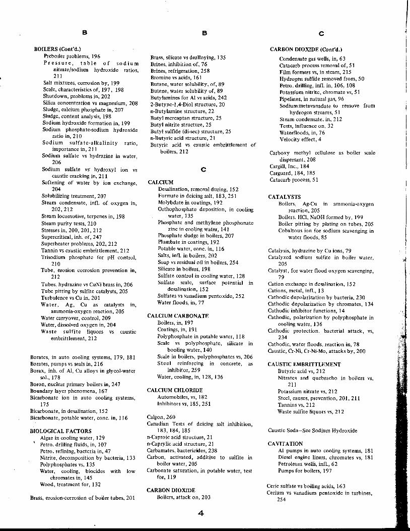
B
BOILERS (Cont'd.)Preboiler problems, 196Pressure, table of sodium
nitrate/sodium hydroxide ratios,211
Salt mixtures, corrosion by, 199Scale, characteristics of, 197, 198Shutdown, problems in, 202Silica concentration vs magnesium, 208Sludge, calcium phosphate in, 207Sludge, content analysis, 198Sodium hydroxide formation in, 199Sodium phosphate-sodium hydroxide
ratio in, 210Sodium sulfa te-alkalinity ratio,
importance in, 211Sodium sulfate vs hydrazine in water,
206
Sodium sulfate vS' hydroxyl ion vscaustic cracking in, 211
Softening of water by ion exchange,204
Solubilizing treatment, 207Steam condensate, infl. of oxygen in,
202,212Steam locomotive, terpenes in, 198Steam purity tests, 210Stresses in, 200, 201, 212Supercritical, inh. of, 247Superheater problems, 202, 212Tannin vs caustic embrittIement, 212Trisodium phosphate for pH control,
210Tube, erosion corrosion prevention in,
212
Tubes, hydrazine vs CuNi brass in, 206Tube pitting by sulfite catalysts, 205Turbulence vs Cu in, 201Water, Ag, Cu as catalysts in,
ammonia-oxygen reaction, 205Water carryover, control, 209Water, dissolved oxygen in, 204Waste sulfite liquors vs caustic
embrittlement,212
Borates, in auto cooling systems, 179, 181Borates, pumps vs seals in, 216Borax, inh. of Al, Cu alloys in glycol-water
sol., 178Boron, nuclear primary boilers in, 247Boundary layer phenomena, 167Bicarbonate ion in auto cooling systems,
175
Bicarbonate, in desalination, 152Bicarbonate, potable water, cone. in, 116
BIOLOGICAL FACTORS
Algae in cooling water, 129Petro. drilling fluids, in, 107Petro. refining, bacteria in, 47Nitrite, decomposition by bacteria, 133Polyphosphates vs, 135Water, cooling, biocides with low
chromates in, 145Wood, treatment for, 132
Brass, erosion-corrosion of boiler tubes, 201
B
Brass, silicate vs dealloying, 135Brines, inhibition of, 76Brines, refrigeration, 258Bromine vs acids, 161Butane, water solubility, of, 89Butene, water solubility of, 89Butylamines for Al vs acids, 2422-Butyne-l,4-Diol structure, 20n-Butylamine structure, 22Butyl mercaptan structure, 25Butyl nitrite structure, 25Butyl sulfide (di-sec) structure, 25n-Butyric acid structure, 21Butyric acid vs caustic embrittIement of
boilers, 212
cCALCIUM
Desalination, removal during, 152Formate in deicing salt, 183, 251Molybdate in coatings, 192Orthophosphate deposition, in cooling
water, 135Phosphate and methylene phosphonate
zinc in cooling water, 141Phosphate sludge in boilers, 207Plumbate in coatings, 192Potable water, conc. in, 116Salts, infl. in boilers, 202Soap vs residual oil in boilers, 254Silicate in boilers, 198Sulfate control in cooling water, 128Sulfate scale, surface potential in
desalination, 152Sulfates vs vanadium pentoxide, 252Water floods, in, 77
CALCIUM CARBONATE
Boilers, in, 197Coatings, in, 191Polyphosphate in potable water, 118Scale vs polyphosphate, silicate in
booling water, 140Scale in boilers, polyphosphates vs, 206Steel reinforcing in concrete, as
inhibitor, 259Water, cooling, in, 128, 136
CALCIUM CHLORIDE
Automobiles, vs, 182Inhibitors vs, 185, 251
Calgon,260Canadian Tests of deicing salt inhibition,
183, 184, 185n-Caproic acid structure, 21n-Caprylic acid structure, 21Carbamates, bactericides, 238Carbon, activated, additive to sulfite in
boiler water, 205Carbonate saturation, in potable water, test
for, 119
CARBON DIOXIDE
Boilers, attack on, 203
4
cCARBON DIOXIDE (Cont'd.)
Condensate gas wells, in, 63Catacarb process removal of, 51Film formers vs, in steam, 215Hydrogen sulfide removed from, 50Petro. drilling, infl. in, 106, 108Potassium nitrite, chromate vs, 51Pipelines, in natural gas, 96Sodiummetavanadate to remove from
hydrogen streams, 51Steam condensate, in, 212Tests, influence on, 32Waterfloods, in, 76Velocity effect, 4
Carboxy methyl cellulose as boiler scaledispersant, 208
Cargill, Inc., 184Carguard, 184, 185Catacarb process, 51
CATALYSTS
Boilers, Ag-Cu in ammonia-oxygenreaction, 205
Boilers, HCI, NaOH formed by, 199Boiler pitting by plating on tubes, 205Cobaltous ion for sodium scavenging in
water floods, 85
Catalysis, hydrazine by Cu ions, 79Catalyzed sodium sulfite in boiler water,
205
Catalyst, for water flood oxygen scavenging,79
Cation exchange in desalination, 152Cations, metal, infl., 13Cathodic depolarization by bacteria, 230Cathodic depolarization by chromates, 134Cathodic inhibitor functions, 14Cathodic, polarization by polyphosphate in
cooling water, 136Cathodic protection, bacterial attack, vs,
234
Cathodic, water floods, reaction in, 78Caustic, Cr-Ni, Cr-Ni-Mo, attacks by, 200
CAUSTIC EMBRITTLEMENT
Butyric acid vs, 212Nitrates and quebracho in boilers vs,
211
Potassium nitrate vs, 212Steel, causes, prevention, 201, 211Tannins vs, 212Waste sulfite liquors vs, 212
Caustic Soda-See Sodium Hydroxide
CAVITATION
Al pumps in auto cooling systems, 181Diesel engine liners, chroma tes vs, 181Petroleum wells, infl., 62Pumps for boilers, 197
Ceric sulfate vs boiling acids, 163Cerium vs vanadium pentoxide in turbines,
254
I~
II

c
C-factor , calculation of, 92Chain lengths, alkyl significance of, 81CHC,225Chelants, boilers, in, 208Chelants, coatings, trisodium salts of
ethylene diamine tetra acetic acid in,223
Chelants, desalination, in, 152Chloramines in cooling water, 129
CHLORIDES
Auto engine cooling system, in, 174Boilers, SCC of, 201, 212Dye baths, hot, 257Influence of, 13Petroleum refinery waters, control in,
52
Water, conc. in potable, 116
Chlorinated amines vs acids, 158Chlorinated hydrocarbon weighting agents,
68
Chlorinated phenols vs microorganisms, 107
CHLORINE
Acids, vs, 161Benzotriazole in cooling water vs, 143Ethanoldiphosphonate demand in
cooling water, 142Mercaptobenzothiazole vs, 142Titanium, vs, 163Water, cooling in, 129
Chlorophenates, bactericides, 238Chlorophenates in cooling water, 129
CHROMATESAluminum vs acid attack on, 241Auto cooling systems, in, 178Barium potassium in coatings, 192Basic lead silico, in coatings, 192Bicarbonates in desalination, 151Biological attack, vs, 234Cathodic depolarization by, 134Coatings, used in, 193Deicing salt, in, 183, 184,252Light, influence on, in methanol, 178Passivation, critical, in cooling water,
133
Petroleum drilling fluids, in, 106Petroleum refineries, in, 43Pitting due to low concentrations, 134Poly phosphates and zinc in cooling
water, 137, 139Phosphate-zinc-iodide in desalination,
151
Pumps, hot water, vs seals, 216Strontium, in coatings, 192Water, cooling, in, 133, 144Water floods vs oxygen, 80Zinc in coatings, 192Zinc in cooling water, 138
Chromium, acetyl acetonate in coatings,194
Chromium oxide in coatings, 192
c
Chromium, hexava1ent in coal slurrypipeline, 256
Chromoglucosates in cooling water, 142Cinnamic aldehyde, structure, 21Citric acid in boilers, 156
COATINGS
Acrylic latexes, inhibition in, 191Alizarin in, 194Alkyl aminoalky1 phosphate, in, 194Alkyds with inhibitors, 192Alkyl benzyl dimethyl-ammonium
chloride, in, 193o-Aminobenzoic acid in, 194Anodic inhibitors in, 190Anionic fatty amido phosphate, in, 194Antimony oxide in, 192Antimony trimethoxide in, 194I-Arginine in, 194Azelaic acid salts in, 191Barium potassium chromate in, 192Barium salts of organic phosphate
esters, in, 194Basic lead silico chromate in, 192Cadmium chromate in, 192Calcium carbonate in, 191Calcium molybdate in, 192Calcium p1umbate in, 191Carbon black in, 192Cathodic inhibitors in, 191Chalk in, 192China clay in, 192Chromium oxide in, 192Chromium acetyl acetonate in, 194Chromium, tris (2-hydroxyaceto-
phenono) in, 194Crevices, for use in, 1932,6-Dimethyl-3,5- heptanedione in, 194Emulsifiable, oil type, 221Esters, 221
Ethane, Bis (1,2-{!ipheny1arsine) in, 194Guanidine chromate, in, 1953,5 Heptanedione in, 194Heptafluoro-1- (2-thienyl)-1, 3-hexane-
dione,1942,4-Hexanedione in, 194Hexafluoroacety1 acetone in, 1944-Hydroxybenzophenone in, 194Humidity, infl. on, 191Inhibitors used in, 190 (table), 192Iminodiacetic acid, disodium salt in,
194
Inert material in, 190Iron oxide in, 192lsatin in, 194Lead, blue in, 192
" carbonate in, 192" red in, 192"suboxide in, 191" titanate in, 192
Linseed oil soaps in, 191Litharge in, 191Magnesium, for, 193Maleic acid, in, 194Mechanism of bonding to substrate, 190Moisture displacing, 221Nitrilo triacetic acid in, 194
5
cCOATINGS (Cont'd.)
Oil and grease, application, 222" flotation, 224" mineral, 221" post-protective procedures, 223" solvent type, 221" vs vapor, 224
Oleoyl sarcosine in, 1942,4-Pentanedione in, 194Picrolonic acid in, 194Pigments in, 190Phosphated fatty alcohols, in, 194Preferential wetting by, 190Pyrocatechol in, 194'Red lead in, 191Resin, 221Salicylic acid in 194Silicones, 221Silico plumbate in, 192Sodium petroleum sulfonate in, 194Sodium su1fate vs, 191Sorbitan fatty ester in, 194Strontium chromate in, 192Surfactants in, 193Talcum, in, 192Tannin after abrasive blasting, 193Titanium dioxide in, 192Toluenechromium tricarbonyl in, 194p-To1ylarsonic acid in, 194Tributyl antimony in, 1944,4,4-Trifluoro-1- (2-thienyl)
-1,3-butanedione in, 194Triphenyl arsine in, 194Wax, 221Zinc acetylacetonate in, 194Zinc chromates in, 190, 192Zinc cyclohexane butyrate in, 194Zinc molybdate in, 192Zinc oxide in, 191Zinc tetroxychromate in, 192
Clarification of boiler feed water, 206
CLEANING
Acids, using, 165Auto cooling systems, 175Bacterial attack, to avoid, 233Surfaces prior to oil and grease coatings,
223
Coagulation of boiler deposits, 197
Cobalt, catalyst \vith sod. sulfite in boilerwater vs oxygen, 205
Cobaltous ion scavenging of oxygen fromwater floods, 85
Coke nuclei, inhibition in process streams,56
Colloidal peat as boiler scale dispersant, 208Computer analysis of petroleum production
inhibitor result s, 74Concentration cells, in boilers, 200Condensate, boiler, HCl in, 199Condensate, gas, NGPA classification, 63Condensate, petro. ref., ammonia in, 45Continuous treating petro. wells, 65, 72Controlled scaling, water floods, 86Cooling towers, absorption of air
contaminants in, 128

c
Cooling towers, tests for, 37Cooling water, chlor amines in, 129Cooling water, chlorine in, 129Cooling water, chlorophenates in, 129Corrater, 31, 37Corrosometer, 30, 37, 86, 238
COPPER
Catalyst in ammonia-<>xygen reaction inboiler water, 205
Catalyst with sod. sulfite in boiler watervs oxygen, 205
Ion displacement test, 32Salt bactericides, 238Sulfate vs boiling acids, 163Water in cooling, 129Water, infl. in potable, 117Water, vs salt, 154
COPPER AND ALLOYSAcid cleaning of, 156Acids, inhibitors vs, 161Alkalis vs, 248Aluminum, effect on, 115, 132m-Amino phenol in alkalis vs, 248Ammonia vs, 45, 212Auto cooling systems, ,infl. on Al in,
175
Beta napthol in alkalis vs, 248Boilers, effect on, 199Borates in ethylene glycol vs, 179Brass vs TCA, Dalapon, 255Catechol in alkalis vs, 248Cresol in alkalis vs, 248Dezincification of brass in alkalis
w/glucose, 248Ethanoldiphosphonate dichromate or
zinc in cooling water, vs, 141Furfuraldehyde in alkalis vs, 248Gallocyanine in alkalis vs, 248Glucose in alkalis vs, 248Glycol-water, inh. in., 178Hydroxy quinoline in alkalis vs, 248Hydrazine, catalytic infl. with, 79Impingement attack, 117, 131Mercaptobenzothiazoles as bactericides,
with,234Methylenephosphonate-zinc in cooling
water vs, 141Petro drilling, vs hydrogen sulfide, 107Petro. ref., in, 44, 56Phloroglucinol in alkalis vs, 248Pipe, flow velocities for, 117Pitting in potable water piping, 117Pitting by polypohsphate-ferrocyanide,
in cooling water, 140Pyrogallol in alkalis vs, 248Quinalizarin in alkalis vs, 248Resorcinol in alkalis vs, 248Salicylaldehyde in alkalis vs, 248Sodium diethyl dithiocarbamate in
alkalis vs, 248Sodium rhodizonate in alkalis vs, 248Tannin in alkalis vs, 248Thiourea in alkalis vs, 248Velocity effects, 4
cCOPPER AND ALLOYS (Cont'd.)
Water cooling vs chromate,polyphosphate in, 137
Water cooling, mercaptobenzothiazoleprotects in, 142
Water, cooling, pH vs pickup in, 136
Coal, slurry pipeline, hexametaphosphatesin, 256
Coal, slurry pipeline, hexavalent chromium,256
Concrete, steel reinforcing bars, inh. of, 259
COUPONS
ASTM D-665-54 designation, 92MIL-I-25017C,93NACE Standard test, 30, 70Petrol. well, monitoring results with,
72,103,110Product pipeline tests with, 92
Crevices, boiler, infl. on causticembrittlement, 200
Crevices, inhibited coatings for, 193Crevices, phosphate benefits in boiler, 210Cronox, 168Crude oil pipelines, 95Cupronickel tubing vs sea water, 131Current-voltage measurements, 31Cyanide as hydrogen blistering catalyst, 49Cyano-ethylated amines vs acids, 158Cyclic and heterocyclic keto amines vs
acids, 158Cyclic loading, infl. in petrol. wells, 62Cyclohexane, water solubility of, 89
CYCLOHEXYLAMINE
Boiler condensate, in, 212, 213Boiler water, in, 204Carbamate, 225Chromate, VPI for nonferrous metals,
225
Nuclear system boiler, in, 247Neutralizer in petro. ref., 55Structure, 25
o
Dalapon, 255Deaeration of boiler water, 204Deaeration, desalination plant, 149Dealloying of brass in cooling water, 131Decam ethy lene-b is-dimethyl hexadecyl
ammonium bromide structure, 23Decamethyleneimine structure, 24n-Decylamine structure, 22Degassing to remove oxygen, 153Dehydration products pipelines, 90
DElCING SALTSCanadian tests, 183-185Carguard vs, 184Chromates vs, 183,252Economics of inhibition, 185Inhibitor evaluation, 185Metaphosphates vs, 183
6
o
DEICING SALTS (Cont'd.)
NACE report, 183Phosphates, urea, formamide, calcium
formate vs, 251Polyphosphate-nitrate vs, 183Sodium hexametaphosphate vs, 185Sodium salt or N-alkyl-sulfonyl-glycine
vs, 185Sodium zinc metaphosphate vs, 185Strontium salt vs, 183Testing inhibitors for, 183Density tests, 38
DEPOSITS
Amines causing boiler, 215Boiler, coagulation, 206Boiler, filtration, 206
Diesel engines, gas turbines from V20Sadditives, 253
Dry, attacks under, 45Paper mills, accumulation, 236
DESALINATIONAluminum for, 151Amine-water solutions, 149Ammonia in, IS 2Calcium, magnesium, removal, during,
152
Carbonates, removal of, 152Cation exchange resins, 152Chelating agents in, IS 2Chromate-bicarbonate in, 151Chromate-phosphate-zinc-iodides in 151Copper removal during, IS 3Dichromate with C steel, in, IS 3Degassing techniques, IS 3Flash distillation, summary of
inhibitors, IS 3, 154Graphite tubes used in, 152Guantanamo, Cuba plant, ISO110,Peru plant, ISOIron removal during, IS 3Kuwait plant, 150Lanzarote, C.1. plant, 150Materials, 149Oxygen control in, 151Nitrites with C steel in, IS 3Phosphates with C steel in, 153Point Lama plant, 150Polyphosphates in, 150Scale control, 149Sodium arsenite in, 153Sodium silicate with C steel in, 153Steel, carbon in, IS 3Vanadates with C steel, 153Zinc ion with C steel, 153
Desalters, pH control, 44Detergency, 38Dextrin, inh. for AI, 162N ,N-Dialkylaniline R=methyl or ethyl
i>tructures, 25Diamines, bactericides, 238Diamines, molecular structures, 82Diamines, petroleum wells, in, 69Diamines, water floods, in, 813,5-Diaminobenzoic acid vs hydrochloric
acid,20

o
3,5-Diaminobenzoic acid structure, 24Diaminoethanolamine structure, 23Diamylamine structure, 22Dianodic, 137Diba~ic amm. phosphate for steel in amm.
nitrate-amm. sol., 255Dibenzyl sulfide structure, 26Dibenzyl sulfoxide structure, 26Dibenzyl sulfoxide vs acids, 158Dibutyl amine structures, 22Di-n-Butyl sulfoxide structure, 26Dichan, 224Dichromate, active region dosages in cooling
water, 134Dichromate for steel in hot sea water, 152
Dicyclohexylamine chromate structure, 25Dicyclohexylamine nitrite structure, 25Dicyclohexylamine in steam condensate,
213
Dicyclohexylammonium nitrite, 224Didecylsulfide structure, 25Diesel engine cooling system, 179Diethyl am'ine structure, 22Diethanolamine structure, 235-Diethylamino-4-pentyne 2001-structure, 20
Diethylenetriamine structure, 23Diethyl sulfide structure, 25Diethylthiophosphate structure, 26Diffusion phenomena in acids, 167Diglycolamine process, 50Dihydrazine phosphate for idle boilers, 206Diisopropylamine + 5% NaG, 149Dilinoleic acid + Na(CHME2) +
mercaptobenzothiazole, 243Dim e thyloctadecylphosphonium bromide
structure, 262,6-Dimethylquinoline structure, 24Dimethylsulfoxide structure, 26Di-n-Octylamine structure, 22Dioctylthiophosphate structure, 264,5-Diphenylimidazole structure, 24
1,3-Diphenyl-l-, 3-Propanedione in coatings,194
Diphenylsulfide structure, 25Diphenylsulfoxide structure, 261,3-Diphenylthiourea structure, 26Dipropargyl ether structure, 21Dipropargyl thioether structure, 21
Di-p-Tolyl sulfoxide structure, 26Disodium hydrogen phosphate for Al in
antifreeze, 241Disodium phosphate in brines, 258Dithionite, 79, 80Dodecylbenzyl aromatic amines vs
hydrochloric acid, 18,D 0 d e cy Iben z yldimethyl-ammonium
chloride structure, 23Dodecylbenzyl q uinolinium bromide
structure, 23N-Dodecyl B-Methylene diamine structure,
22
Dodecyl pyridinium xanthate, 158Drawing oil, rust preventive for, 223Duomeen-T for petro. wells, 70
E
ECOLOGICAL FACTORS
Blowdown disposal, cooling water, 127Chromates in cooling water, 135Phosphates in potable water, 124Sulfonated tannins, sugar acids,
blowdown problem, 142Thermal contamination, 126Tests, laboratory, 39Water, cooling, blowdown, phosphate
removal, 144Water, cooling, blowdown, zinc
removal, 144Water cooling, chromate removal from
blowdown, 144Zinc in potable water, 124
EDT A, 77, 208
ECONOMICS
Antifoulants in petr. ref., 57Boron salvage at nuclear plant, 247Chromate-polyphosphate-zinc in
cooling water, 139Coal slurry pipeline, 256Digesters in paper mills, 236Deicing salt inhibition, 184Desalination, 148Dichromate zinc in cooling water, 138Natural gas pipelines, 97Octadecylamine in boilers, 215Petroleum, crude tanks and pipelines,
98
Petro drilling, 104Petroleum production, 61Petroleum ref., 48Petrol, sweet oil wells, 63Street deicing salts, 251Polyphosphates in cooling water, 136Polyphosphate, polyphosphate-zinc in
potable water, 123Value of inhibition, 2Vehicles, oil and grease coatings, 223
Economizers, boiler deposits, 197Economizers, polyphosphates, in boiler, 207Electrical resistance measurements in water
floods, 84Electrical resistance probes, 238Electron acceptors, 13Embrittlement cracking, 108Emulsifiable coatings, 220Emulsifiable oils for auto engines, 177, 179Emulsification problem, products pipelines,
91. Emulsification. WSIM test for, 47
EMULSIONS
Blocks, squeeze treating, 66Petro wells, in, 62Petro wells, with heavy liquids, 68Problems with, 37
Engines, automobile, 173Engines, oil and grease coatings for, 223Environment, alterations of, 48Erdco CFR device, 58Erosion, corrosion in boilers, 201, 212Erosion, petro wells, in, 62
7
E
Estosolvan process, 50Ethane (bis (1,2-diphenylarsine) in coatings,
194
Ethanolamine, petro. ref., 44Ethanolamine, sulfur removal, 50Ethanoldiphosphonate mixtures in cooling
water, 141Ethoxylation, significance of, 81Ethylamine structure, 22l-Ethylamino-20ctadecylimidazoline
structure, 23Ethylenediamine tetracetic acid as boiler
cheland, 208Ethylene glycol, in auto radiators, 173, 177Ethylene glycol, borates in, 179Ethylene diaminetetraacetic acid in water
floods, 77Ethylene glycol, chromates in, 178Ethyleneglycol bis-dibenzylxanthate
structure, 26Ethylene oxide adducts of abietyl amines vs
acids, 158Ethyl sec-butylamine desalination, 149Ethyl-noOctyl sulfide structure, 256-N-Ethylpurine structure, 234-Ethylpyridine structure, 24
F
Field tests, See Testing, on site
FILM
Formers, concentration, 47Measurements, 32Moisture, displaced by coatings, 221Persistency, 36Water floods, stability in, 81
Filming inh. vs 230-260 C, 47Filming inhibitors for petro. ref., 45Filter, by-pass, in auto cooling systems, 179Filtration of boiler deposits, 206Fatigue, film formers vs, 52Fatty acids in auto cooling systems, 179Fatty acids, composition, 83Fatty acids in petro. ref., 43Ferric bromide vs boiling oxalic acid, 163Ferric chloride vs boiling oxalic acid, 163Ferric ions, infl. on acid cleaning, 157Ferric oxalate vs boiling oxalic acid, 163Ferrocyanide-polyphosphate in cooling
water, 140Ferrocyanide in hydrogen treating, 49Ferrous metals, acids vs, 156Fingerprints, oil and grease vs, 220Fingerprints, removers, 221Fingerprints, water emulsifiable coatings vs,
221
Firearms, oil and grease coatings, 223Fire floods, organic acids in, 77Fire floods, secondary recovery, 76Floc, boiler, removal of, 206Flotation application in tankships, 100Flotation type coatings, 224Fluorides, fluorosilicates vs Al in cooling
water, 136

F
Fluorides, potable water, conc. in, 116
FOAMING
Boilers, 199, 209Desalters, in, 44General, 35, 39MEA systems, 51
Fogging in tankships, lOOFog treatment, natural gas pipelines, 97Formaldehyde-amide condensate as boiler
antifoams, 210Formamide for AI, 243Formamide in deicing salt, 183, 251
FOUUNGAromatics, infl. on, 56Erdco CFR coker test device,S 8Dispersants vs, 56Heterocyclic hydrocarbons, infl. on, 56Hot wire test, 59JFTOT test device for, 58Olefins, infl., 56Paraffin infl. in, 55Petro ref., Cu, V, Ni infl. on, 56Petro ref., free radicals infl. 56Petro ref., organic,S 5Prediction by tests, 55Surfactants vs,S 6Temp. stability of compounds vs, 56
Fourdrinier wire attack by bacteria, 233Freeport, Tx desalination, 149Free radicals' infl. on petro. ref. fouling, 56Freezing process, desalination, 149Freundlich isotherms, 17Friction, products pipelines, calculating C
factor, efficiency, 92Fuel, aircraft, MIL test for inhibitors, 91
FUEL OIL
Borax vs, 256Chromates vs, 256Domestic tanks, inh., 256Sodium nitrite, alkaline buffer vs, 256
Fungi,228Fungicide treatment of wood cooling
towers, 132Furfuraldehyde structure, 21Furfuraldehyde in alkalis vs Cu alloys, 248Furfural units, control in, 52
G
Gallocyanine in alkalis vs Cu alloys, 248Galvanic attack, copper in drilling fluids,
, 107
Galvanic attack, polyphosphates in coolingwater vs, 135
Galvanic attack, water, potable in, 117
GALVANIC COUPLES
Al-Cu, borates vs in ethylene glycol, vs,179
Acid cleaning, during, 157
G
GALVANIC COUPLES (Cont'd.)
Auto cooling systems, 34AI-steel, inh. vs, 242Boilers, Cu-Fe, in, 200Measurements, 32Oil and grease compounds vs, 187
Galvanic tests in glycol-water sol., 178
GASES
Air-contaminated, amine oxygenatedpetroleum acid in, 87
Equilibrium in steam, 203Explosive, during acid cleaning, 157Natural, mono ethanolamine
desulfurizer of, 97Petro. ref., phase in, 43Poison, generated during acid cleaning,
157
Potassium carbonate, hot, sweeteningof,51
Processing, 50Stripping oxygen from water floods, 84Treatment modes, 46, 51Venting in water floods, 81Well characteristics, 61Well packer fluid tests, 35
Gasoline, rust test, turbine oil, 93Gasoline, water solubility in, table, 89Glassy polyphosphate for water floods, 82Glucose for AI, 243Glucose in alkalis vs Cu alloy, 248Glucosates as dispersants in boilers, 208Glycol weighting agents, 68Graphite, tubes in desalination, 152Graphitization, cast iron during acid
cleaning, IS 7Grease coatings, 220Guantanamo, Cuba, desalination plant, 150Guanidine chromate in coatings, 195
H
Halides vs acids, 161Halogenated aromatics vs acids, 158Halogen ions vs boiling oxalic acid, 163Hardness, potable water criterion, 116Heat exchangers, antifoulants for, 57Heat exchangers cleaning with acids, 157Heat exchangers in cooling water systems,
133
Heaters, potable water, liSHelmholtz layer, 7N-Hexadecyl propylene diamino salicylate,
19
N-Hexadecyl propylene diamine structure,22
N-Hexadecyl propylene, vs hydrogensulfide, 18
Hexafluoroacetyl acetone in coatings, 194Hexametaphosphates in coal slurry pipeline,
256Hexametaphosphates vs deicing salt, 185Hexamethyleneimine benzoate structure, 24Hexamethyleneimine structure, 22
8
H
He xamethyleneimine-3, 5-dinitrobenzoatestructure, 24
Hexamethyleneimine m-nitrobenzoate, VPI,226
Hexamethylene tetramine for AI, 243Hexamethylene tetramine structure, 22Hexamme inh. vs aC1Qsfor Zn, Ib2Hexane, water solubility in, 89HF alkylation, 52Hot dip petrolatum coatings, 220Hot wire fouling test, 59Humidity cabinet, 222Humidity, infl. on coatings, 191
HYDRAZINE
Ammonia reaction, 205Boilers, CuNi, brass tubes, vs, 206Boilers, in, 205Nuclear systems, in, 247Oxygen, control of dissolved in boilers,
204
Quinone catalyst for, 80Sulfate in alkalis vs Cu alloys, 248
Hydrobromic acid, 161Heptafluoro 1-(2-thienyl) -1,3-Hexanedione
in coatings, 194Heptane, water sol. in, 89Heptene, water sol. in, 89Hydrocarbons, petro ref., liquid in, 43Hydrocarbons, specific gravity vs viscosity,
(table),92Hydrocarbon tests, 34Hydrochloric acid cleaning, 156Hydro desulfurizers, 52Hydrodesulfurizers, antifoulants in, 56Hydroiodic acid, 161Hydrocracking, 44
HYDROGEN
Catalysts in blistering, 49Embrittlement in oil base muds, 112Embrittlement in petro. drilling, 108Embrittlement from petro. well packer
fluids, 110Evolution measurements, 31Gas generated during acid cleaning, 157Sodium met a vanadate vs CO2 in, 51Temperature, attack at high, 42
Hydrogenase, infl. of, 230
HYDROGEN SULFIDEAlkaline arsenite-arsenate solution to
absorb, 51Al in condensate with ammonia, vs, 243Bacteria produced in c!Joling water, 129Boilers formed in, 199Carbon dioxide removed from, 50Catalyst in hydrogen blistering, 49Copper carbonate vs in petro. drilling,
107
Crude petroleum, infl. on pipelines, 95Electrochemical reduction in drilling
fluids, 108Embrittlement of oil well casing collar,
110

H
HYDROGEN SULFIDE (Cont'd.)
Heat exchangers, inh. in, 51N-Hexadecyl propylene vs, 18Hydrodesulfurizer units, infl. in, 52NACE report on petro. wells, 64Oxygen scavenging, infl. on, 85, 86Petro wells, solutions for attack, 64Petro drilling, control in, 103, 106Petro drilling, metal salts vs, 107Pipelines, in natural gas, 96Process stream analysis, infl. on, 46Stainless steels vs,S 2Tests, infl. on, 32Water floods, gas stripping from, 84Water floods, inhibition in, 76, 80Water floods, oxygen scavenging,
initiation by tertiary butylhydro peroxide, 86
Hydrosulfite, 79, 80Hydroxyquinoline in alkalis vs Cu alloys,
248
Hydroxyquinoline structure, 24Hydroxides, calcium chloride, formation in
boilers from 202
Tris. (2-Hydroxyacetophenone) chromiumin coatings, 194
4-Hydroxybenzophenone in coatings, 194I-Hydro xy ethyl-2- octadecylimidazoline
structure, 23
110, Peru desalination plant, 150Imidazole, structure, 24Imidazolines, molecular structure, 82Imidazolines in steam condensate, 214Imidazolines in water floods, 81,83Iminodiacetic acid disodium salt in coatings,
194
Impingement attack on copper piping, 117,131
Inorganic fouling in petro. ref., 55
INHIBITORSAcid systems, for, 156Adsorbent, evaluation of, 16Alkaline earth sulfonates, 19Aluminum, for, 178,240Anodic function, 14Application, 2, 65Cooling water analysis, 144Batch, extended period treatment, 67Books on, 5Boilers, practices in, 203Classes of, 11, 12Coal slurry, 256Concentration effects, 165Definition, 1Deicing salts, evaluation for, 185Design principles, 13Economics, 2Effectiveness, theoretical aspects, 12Efficiences of various in auto antifreeze,
178
Film persistence, 36, 81Galvanic couples, vs, 34
INHIBITORS (Cont'd.)
High density, 40History, 2Manufacturers, report on, 5Materials problems with, 3Mechanism, 28Measurement techniques, 20Microorganisms vs, 228NACE activities, 5Navy Dept., approved list, 91Nitrates in aircraft fuel, 232Nitrogenous, long chain in boilers, 214Oil & grease coatings, in, 220Oil soluble for refined products
tankships, 100Organic for oxygen in water floods, 86Organic, types for petro wells, 69Organizations involved with, 4Petro. wells, concentrations used in, 65Petroleum wells, economics, 61Petro. well drilling and packer fluids,
for, 112Polymethyleneimines, 15Polyphosphates in boiler feedlines, 207Properties, 28, 37, 38Screening by electrochemical
techniques, 20Sea water, 250 F, 148Ships, nuclear propulsion systems, used
in,3Slug, circulate and park technique, 67Sodium chromate and nitrite in
products pipelines, 91Solubility tests, 37Squeeze application in petro. wells, 66Structures of some, 20Synergism, 166Thiobenzene, 14Tubing displacement technique, 66Vanadium pentoxide, sodium sulfate vs,
252Vapor phase, 224Viscosity measurements, 37Water, 149 C, for, 216Water flood, organics, good for, 81Water flood, vs oxygen attack in, 86Weighting agents, 65
Intermittent treating, petro. wells, 65Iodine vs acids, 161Ion exchange, boiler feed water
pretreatment by, 203Ion exchange in water floods, 77
IRON
Cast, graphitization during acidcleaning, 157
Ca talyst for water flood oxygenscavenging, 86
Content measurements, 47, 72Magnetic, control in boilers, 208Oxide + tannin in coatings for steel, 193Petro. ref. infl. on fouling, 56pH elevation in potable water, 118Polyphosphate stabilization in potable
water, 124Salts vs acids, 161Salts as boiler deposit coagulant, 197
9
IRON (Cont'd.)
Water, conc. in potable, 116
lsatin in coatings, 194lsomyl alcohol + wetting agents as boiler
antifoams,210lsobutane water solubility in, 89lsopentane, water sol. in, 893-lsopropyl arnino-1-Butyne structure, 21Isotopes, tests using, 32, 67
Jet fuel oxidatIon tester, 58Jet fuel water tolerance, 39JFTOT device, 58JP-4, ASTM rust test, 93
KKaolin vs vanadium pentoxide-sodium
sulfate attack, 252Keiselguhr vs vanadium pentoxide-sodium
sulf'Ide attack, 252Kuwait desalination plant, 150
L
Langelier's formula, 119Langmuir adsorption calculations, 166Langmuir isotherms, 17Lanthanum vs V20S, attack in turbines,
254
Lanzarote, Cl desalination plant, 150Laurates for Al, 243Laurylmercaptan structure, 25
LEAD
Acetate vs acid cleaners, 157Azelate in coatings, 191Blue in coatings, 192Calcium plumbate in coatings, 192Carbonate in coatings, 192Nitrate vs acids, 157Red, in coatings, 191Silicates to control pickup in cooling
water, 135Silicop1umbate in coatings, 192Suboxide in coatings, 191Titanate in coatings, 192Water, potable, dissolved in, 116
Light, bacterial attack, infl. on, 233Light, chromates in methanol, infl., 178Lignins as dispersants in boilers, 208Lime treatment of sewage effluent, 130Linoleates for AI, 243Linoleic acid, dimer of, structure, 21Linseed oil soaps in coatings, 191Liquids, use of heavy in petro. wells, 68Liquefied petroleum gas pipelines, 91Litharge in coatings, 191Lithium chloride vs deicing salt, 183LPG pipelines, 91Lubricants, coatings compatible with, 221Lubricants, petro. drilling, in, 1032,4-Lutidine structure, 24

M
Macaroni tubing, 68Machinery, oil and grease coatings on, 223Magna Corp., 30, 238
MAGNESIUMBoiler feedwater, infl. on, 207Desalination, removal during, 152Hydroxide in boilers, 197Hydroxide inh. for reinforcing steel in
concrete, 259Lithium, aluminum chlorides vs deicing
salt, 183Silicates in cooling water, infl. of, 135Water floods, in, 77Water, conc. in potable, 116
Magnetite in boilers, 199Maleic acid in coatings, 194Maleic acid structure, 21Manganese, catalyst for water flood oxygen
scavenging, 86Manganese naphthenate vs V20S in
turbines, 254Manganese, conc. in potable water, 116MBT-See MercaptobenzothiazoleMEA- See MonoethanolamineMeasurements-See TestsMembrane method, desalination, 149Materials selection, alternate to inhibition, 3
MECHANISM
Adsorption, 12Aerobic bacteria, 231Alkali bichromate VPI, 227Alkalis, metal protection against, 248Alkyl chain length, infl., 16Ambiodic function, 14Amines, adsorption, 81Aminobenzoates, 226Anions, effect on passivation, 178Benzotriazole in cooling water, 143Biological attack, 228, 237Cathodic functions, 14Calcium carbonate scale protection in
potable water systems, 120Caustic attack, 201, 246Chromate orthophosphate in cooling
water, 137Chromate polyphosphate, zinc in
cooling water, 138Coatings bond to substrate, 190Complexing with metal atom, 19Cyclohexylamine chromate, 225
Electrical double layer, 7EmulsiIiable oils in auto cooling system,
179Ferrous sulfate protection, AI-brass in
sea water, 143Filming inhibitors, 45,214Free energy, 8Helmholtz layer, 7Hydrogen blisters, 49Ion exchange boiler water pretreatment,
204Octydecylamine in boilers, 213Oil and grease coatings, 220
M
MECHANISM (Cont'd.)
Metal corrosion, 7Metavanadate vs C02, 51Methylenephosphonate-zinc in cooling
water, 141Mixed molecules, 14Passivation by chromates, 134Passivity in acid environments, 167Polyphosphates vs calcium carbonate
scale in boilers, 207Polyphosphates, vs Cu pickup, cooling
water, 136Polyphosphate function, in cooling
water, 136Polyphosphate-zinc in cooling water,
139
Phosphonates in cooling water, 140Polarization diagrams, 10Sodium chromate, nitrate on steel, 90Sodium hydroxide inhibition of boiler
corrosion, 204Structures, influence of molecular, 19Structure, infl. of oil coatings, 221Sulfide Itlms vs pH, cyanides, 49Surfactants vs fouling in petro. ref., 156Temperature influence, 13Vanadium pentoxide attack, 252Vapor phase inhibition, 224Zinc, cadmium and strontium chromate
in coatings, 195
M er c apto benzothiazole applicationtechniques, 142
Mercaptobenzothiazole in glycol and/or tapwater, 178
Mercaptobenzothiazole, ammonium nitrate,vs, 255
Mercaptobenzothiazole, in auto coolingsystems, 181
Mercaptobenzothiazole, in cooling water,142
Mercaptobenzothiazole, sod. salt in glycoland/or tap water, 178
2-Mercaptothiobenzole structure, 26Milchem, 168Mill scale, removal by pickling, 18Miscible flood, secondary recovery, 76Mercury, in cooling water, 129
METALSAlkalis, attacked by, 245Cations, infl., 12Corrosion mechanism, 7Oxides vs vanadium pentoxide attack,
252
METALS, NONFERROUSAmines vs in boiler water, 204Chromic acid, n-butyl alcohol as vapor
phase inhibitors, 225Cyclohexylamine chromate, vapor
phase inhibition, 225Polyphosphates with, 122Vapor phase inhibitors for, 225, 226Staining, VPl vs, 226Water, cooling, silicate protection, 135Water, potable, silicate protection, 121
10
M
Metal salts, infl. on acid attack, 164Metallurgical factors, AI, related to
inhibition, 240Metaphosphates vs deicing salts, 183Metasilicate for Al in glycol-w~ter sol., 178Methoxy propanol as auto engine antifreeze,
177
Methyl alcohol antifreeze in auto coolingsystems, 177
Methylamine structure, 222,2-Methylene bis (4-chlorophenol) vs
nitrate reducing bacteria, 133Methylenephosphonate-zinc or dichromate
in cooling water, 140Methylpropylamine structure, 22Methyl styrene-maleic anhydride as boiler
dispersant, 208Monoamine, molecular structures, 82Monoamines for petro. wells, 69Monoethanolamine, antimony chI. as inhib.
for, 51Monoethanolamine, desulfurization of
natural gas, 97Monoethanolamine, structure, 23Monoethanolamine, sulfur removal with, 51
MORPHOLINE
500 C, 4410 psi, stability in Water at,247
Structure, 23Boiler water, in, 204Petro. ref., neutralization, 55Steam condensate, in, 212
N
NACE
Cooling water inhibitor manual, T7B,127
Coupons, standard l]1etal test, 30, 70
Deicing salt corrosion report, 183Economics of cooling water corrosion
control, T7 A, 127Petro. inh., static and dynamic tcsts, 70Petro. well acid cleaning standard, 69Products pipeline in-line recommended
practice, 93Sulfide cracking resistant materials for
valves for production and pipelineservice, 64
Test, inhibitor methods, 40Testing reports and standards, 4
Naphthoquinone for AI, 243Naphthenic acids, 49Natural Gasoline Producer's Association
classification of gas condensate wells,63
Neodymium vs V20S in turbines, 254Nernst equation, 168Neutralization of acids, 44Neutralizers other than ammonia in petro.
ref., 55Nickel, acids vs, 163Nickel, chromates as Al inh., 241Nickel, petro. ref., infl. on fouling in, 56
I
.~

N
Nickel, water floods, oxygen scavengingusing Ni ion catalyst, 86
Nicotinic acid for AI, 243Nicotinic acid structure, 24Nitrates, aircraft fuel, vs bacteria in, 232Nitrates, auto cooling systems, in, 181Nitrates, potable wattr, conc. in, 116Nitrides, infl. in SCC, 201Nitrilotriacetic acid as boiler chelant, 208Nitrilotriacetic acid in coatings, 194Nitrilotris, 140
NITRITES
AI, for in glycol-water sol., 178Cu, brass inh. in glycol-water, 178Desalination, with C steel in, 153Pump, hot water, vs seals in, 216Water floods, vs oxygen in, 80
Nitrogen, corrosion, infl. on, 49Nitrogen, in petro. ref. streams, 43Nitrogen, sewage effluent, in, 131o-Nitrophenol dimers as boiler dispersants,
208
NTA,208NTMP-See MethylenephosphonateNuclear reactor, boilers, treatment, 201,
212,247
o9,1 I-Octadecadienoic acid (dimer of linoleic
acid) structure, 21Octadecylamine acetate, 214Octadecylamine bacterial attack, vs, 234Octadecylamine, steam condensate, in, 213Octadecylamine, structure, 22Octane, water sol. in, 89n-Qctylamine structure, 22
OIL
Boilers, max. limits in, 199Coatings, 220Contamination of boiler water, 198Films, on pumps, valves. 221Grease rust preventive, SAE data on,
186
Phase, infl. on performance, 45Soluble inhibitors, for products
pipelines, 91Soluble, with adsorption inh. for AI,
245
Vapor space in tanks containing TCA,prot. by, 254
Wells-See Petroleum
Olefinic polymers vs acids, 158Oleyldiamine for salt water disposal wells,, 85
Onium ions vs acids, 158Organic acids vs acids, 158Organic sulfides vs acids, 158Organic Thiocyanates vs acids, 158Organic sulfur-based bactericides, 238Oxalic acid for zinc, 162d-Qximino-{3' vinyl quinuclidine structure,
22
o
OXYGEN
Amines, boiler water, infl., 204Amine oxygenated petroleum acids vs,
87
Ammonia reaction in boilers, Ag, Cu ascatalysts, 205
Auto cooling systems, in, 174Benzotriazole resistance to in cooling
water, 143Boiler feed water, control of dissolved
in, 204Boilers, pitting by, 200Boiler, stress corrosion cracking, infl.
on,201Carbon, activated, sulfite additive to
remove from boilers, 205Catalysts for scavenging by sulfite, 85,
205
Caustic attack on C steel, vspolysulfides, 246
Chelants vs, 87Coal slurry, in pipeline, 257Desalination, control in, 151Hydrogen sulfide infl. on water flood
scavenging, 80, 85Oil and grease coatings, vs, 223Petro. drilling, scavenging from fluids,
104,106Petro. ref. infl. on, 43, 56Pipelines, natural gas in, 96Pyrocatechols vs, 87Sodium sulfite, metabisulfite and sulfur
dioxide scavengers in water floods,85
Sarcosines vs, 87Scavengers in petro. drilling, 103Scavenging from water floods, 84Secondary recovery, infl. in, 76Steam condensate, in, 202, 212Steam stripping from boiler feedwater,
204
Sulfite scavenging from water floods, 84Sulfur dioxide scavenging, cobaltous ion
catalyst, 85Temp. infl. on attack, 202, 205Vanadium pent oxide-sodium sulfide,
absorption of, 252Water floods, cobaltous ion catalyst for
scavenging, 85"catalyst for scavenging with
sulfite, 85" chromate vs, 80" hydrogen sulfide scavenger, 86" inhibition, 80, 86" measurement, in 84" scavenging in, 77, 79, 86" stripping with gas, 84
Water, potable, infl., 115
p
Packaging VPI tests outdoors, 225Pairmeter, 31Paper, for VPI packaging test, 225,Paper miiIs, biological attack in, 238
11
Paraformaldehydt.' Vs microorganisms, 107Passivators, concentta:tion, 4',Passivity, mech. in acids, 167Pectin for AI, 245
2,4-Pentanedione in coMing$', 194Pentane, water solubility in, 89Persistent filming, petrolet>rn wells, te sts, 72Perspiration attack on coupons, 93Petrolatum coatings, 220Petrolite Corp., 31Petrochemical vessels, cleaning with acids,
156
PETROLEUM
Fluids, characteristics, 62Limestone, adsorption properties, 67Sandstone, adsorption properties, 67Sour oil or gas-See Hydrogen SulfideSulfide cracking, NACE report on
materials, 64Sulfonates in auto cooling systems, 179Tanks, crude, protection, 98Tankships, crude, prot., 99
PETROLEUM DRILLING
Acid gases infl., 108Alkalies used in, 106-108Amines, in, 106-109Application inhibitors, 109Biological efrects, 107Carbon dioxide effects, 106Causative factors in, 102Concentration cells, 105Chlorinated phenols vg microorganisms,
107
Chromates in fluids, 106Copper influence, 107Coupons, down-hole, 110Economics, 104Failure analysis, 103History, 103Hydrogen in, 108Hydrogen sulfide control, 106Lubricants, 103Mechanical factor, 102Metallurgical factors, 102Metal salh vs hydrogen sulfide, 107Microorganisms, 102, 107Mud, oil, 109Mu<!,water base, 104Oxygen scavenging, 103, 104, 106Paraformaldehydes vs microorganisms,
107
Quebracho extract, 103Salt solutions, satUrated, 109Sodium chromate, 103Sodium hydroxide, 103, 109Sodium nitrite, 103Sodium sulfite, 103Stress influence, 108Temperature infl., 102, 107Time factors, 102Water fresh. in, 106Zinc carbonates, oxide vs hydrogen
sulfide, 107

p
PETROLEUM WELLS
[Packer Fluids]Biocides, inhibitors' for, 110Characteristics of, 113Gas well, 35Hydrogen embrittlement from packer
fluids, 110Medium density packer fluids in, IIIMud as packer fluid, 110Oil packer fluids, IIIProperties, 103, 104Sulfides in, 107Temperature, infl. on 35Tests, 35Water-base, III
PETROLEUM WELLS
[Primary Production]300 oil, description, 72Abrasion, infl., 62Acid c1eanmg, 69Acidizing of, 157, 164Application modes, inhibitor, 65Bactericides, 69Cavitation infl., 62Characteristics, 61Completion method, infl., 61Computer analysis of result, 74Concentrations of inhibitors in, 65Continuous treating, 65, 72Corrosivity classification, 63Coupons, monitoring with, 72Cyclic loading, 62Depth influence, 61Drop size ratio test, 71Easily killed, techniques for, 68Emulsion infl., 62Erosion infl., 62Extended period batch treatment, 67Fluids, determining corrosivity, 62Gas condensate, carbon dioxide infl., 63Gas, fall rate of inhibitors in, 67Gas, NGPA classification, 63Hydrochloric acid, use in, 157Hydrofluoric acid use in, 157Hydrogen sulfide, corrosivity of, 64Intermittent treating, 65Inhibitor film persistence (table), 70Inhibitor, high density, 40Inhibitor properties, 67Liquids, heavy, 68Persistent filming, on-site tests, 72Predicting corrosivity, 63Pumped, amine oxygenated petroleum
acid vs oxygen in, 87Pumped, heavy liquid treating of, 68Pumped, squeeze treatment, 67Quality control, specification, 73Reverse wetting, 66Slug, circulate and park technique, 67Squeeze application, 66Statistics on inhibitor performance, 71Stress in, 62Temperature infl., 62, 71Tests, isotope, 67Tests, on-site, 72Treating intervals, 65
p
PETROLEUM WELLS (Cont'd.)[Primary Production] (Cont'd.)
Tubing displacement technique, 66Velocity infl., 62Water, infl., 63Wear in, 62Weighting agents, inhibitor, 65
PETROLEUM WELLS
[Secondary Recovery]Fire flood, 76Miscible flood, 76Steam floods, 76Water floods, 76Water flood, acid neutralization in, 78Water, hot and steam floods, 77Water flood, infl. of oil absence, 80Water floods, pH determination, 78
PETROLEUM REFININGAcids in process stream, 45Amines,45Ammonia value in, 46Antifoulant s, effect,S 7Application equipment, 46Aqueous phase, 43Aromatics, olefins, heterocyclic
hydrocarbons, infl. on fouling, 56Bacterial growths, 47Chlorides, control in water, 52Chloride decomp.,in, 44Chromates in, 43Oeaningwithacids, 157, 165Concentration effect of volume
throughput on fouling, 56Concentration factors, 47Copper alloys in, 44Copper, iron, nickel and vanadium infl.
on fouling, 56Desalter,44Dispersants and surfactants vs fouling
in, 56Distilling unit life comparisons,S 7Dry corrosion in, 42Economics of inhibition, 48Emulsification in, 47Environment characteristics, 42Erdco CFR coker foulant test device,
58
Film formers vs fatigue failure,S 2Filming inhibitor for, 45Fouling, 150-370 C, 47
" control in, 55" free radicals' infl., 56" organics in, 55" oxygen infl., 56" testing potential, 58
Furfural units, 52Gas phase, in, 42Gas processing units, 50HF alkylation, 52Hydrocarbon, liquid phase, 43Hydrogen blistering in, 49Hydrogen sulfide in, 42Inhibitors for, 42JFTOT device for fouling tests, 58Metallurgical solutions of corrosion, in,
48
12
p
PETROLEUM REFINING (Cont'd.)
Naphthenic adds. in, 43, 49Neutralizers in, 45; 55Nitrogen compounds in, 43, 46Paraffin, infl. on fouling, 55
Processes amenable to inhibition, 49Process ch\lnges in, 52Process steam analysis, 46Stress corrosion cracking control in, 52Surfactants in, 47Surface condition, inn. on
concentration, 47Tempera ture limits of inhibitors,
antifoulants, 47, 56Waste streams for cooling in, 43Water pH, infl. of, 43Water, sources, 43, 47Weight loss tests, 46
pHAlkaline and related systems, 246Bacterial attack, ranges for, 233Boiler alkalinity for phosphate control,
207
Boiler, control in, 204, 210, 247Calcium plumbate infl. in coatings, 191Carbonic acid conversion by
morpholine, range, 212Chromate sensitivity to, 134Condensate, critical range in, 202Control of, 45Cooling water adjustment, 128Copper pickup in cooling water,
adjustments vs, 136Desalination, sea water, 149Mercaptobenzothiazole in cooling
water, 142Phosphates, infl. in boilers, 197Polyphosphates, potable water treated
with, 121Polyphosphates, in cooling water, 135Silicates, optimum for potable water
treatment with, 121Water, 149 C, significant at, 216Water, cooling, chromate treatments,
144, 145Water cooling, polyphosphate-zinc,
range in, 139Water floods, infl. in, 78Water, potable, elevation of hard, 118
Phenolpthalein alkalinity vs methyl orangealkalinity in boilers, 207
Phenol in alkalis vs Cu alloys, 248Phenols, water floods, in, 79Phenothiazine vs acids, IS 8Phenylbenzimidazole structure, (1,2), 24,
25
Phenylbenzyl sulfide structure, 26Phenyldiethanolamine structure, 24Phenylethanolamine structure, 23Phenylethylmercaptan structure, 25Phenylquinoline for AI, 243Phenylthiourea structure, 26Phenylthiourea as VPI, 226Phloroglucinol in alkalis vs Cu alloys, 248
"T
I1I
I
I
II
It
JI

p
PHOSPHATES
Auto cooling systems, in, 180Boilers, optimum concentrations in,
210
Boilers, control of, 207Boiler economizer, use in, 207Boiler feed lines, reversion in, 207Chromate mixtures, desalination for,
150
Deicing salt, in, 251Glassy vs oxygen in water floods, 86Phosphonate polymeric dispersions in
cooling water, 145Steel, carbon, in 250 F sea water with,
153
Zinc + sulfonate in potable water, with,124
Phosphoglucosates in cooling water, 142Phosphonate, phosphate or polymeric
dispersions in cooling water, 145Phosphonates in cooling water, 145Phosphoric acids vs acids, 158Phosphorus, organic compounds vs acids,
158
PIPEUNES, CRUDE OILAluminum, 95Internal coatings, 95Oil properties, infl. on corrosion, 95Sediment infl., 95Velocity, infl., 95
PIPELINES, NATURAL GASCarbon dioxide in, 96Fog treatment, 97Hydrogen sulfide in, 96Inhibition of, 96Organic sulfophosphates in, 96Oxygen in, 96
PIPELINES, PRODUCTSApplication techniques, 91Coatings, 92Corrosion, causes in, 90Coupon testing, 92, 93Dehydration, 90Efficiency considerations, 92Emulsification problems, 91Inhibitors for, 90, 91MIL-I-25017C, test, 91NACE STD.TM-oI-72 test, 93Oil soluble inhibitors, 91Propane, butane, dehydration, 90Sodium chromate in, 90Sodium nitrite in, 90Sulfonated mahogany oil, 89Water in, 90WISM test, 91
Pickling, 18, 156Picoline (2-3-4) structure, 24·Picrolonic acid in coatings, 194Piperidines vs acids, 158
PllTlNG
Boiler, catalyst on tubes, 205Chromate, from low concentrations of,
134
p
PITTING (Cont'd.)
Copper in cooling water, 140Copper in potable water, 117Deposits, infl. of boiler, 200Evaluation in bacterial attack, 233Petro. drilling, infl. on, 105Pulp and paper mills, in, 236Water, potable systems, pH infl., 122
Plastic lined pipe in water floods, 78Point Loma desalination plant, 150
POLARIZATIONCathodic, 11Diagrams, use of, 10Evaluation by techniques, 16Mechanisms, 10Positive, 9
Polar oil for Al in glycol-water sol., 178Polar oil for copper, brass in glycol-water,
178
Polar types of inh., 46Polyacrylic acid vs deposits in cooling water,
130
Polyacrylamides vs deposits in coolingwater, 130
Polyacrylates as boiler dispersants, 208Polyamines, molecular structure, 82Polyamines in water floods, 83Polyethyoxalates for petro. wells, 69Polymeric amines, 15Polymeric coagulants for boiler deposits,
197
Polymeric dispersions withphosphate-phosphonates in coolingwater, 145
Polymerized 4-hydroxy piperidenes vs acids,158
Polymer floods, description, 80Polymers for boiler feed water clarification,
206
Polymethylene amines vs acids, 158Polyoxyalkylene glycol antifoams for
boilers, 209.POLYPHOSPHATE
AI vs in cooling water, 136Biological attack, vs, 234Boiler makeup water, used in, 206Boiler scale, vs, 206Chromate-zinc in cooling water, 139Ferrocyanide in cooling water, 140Metals, nonferrous, with, 122-Nitrite vs deicing salts, 183Red water, vs, 121Silicate in cooling water, with, 140Silicates in potable water, with, 124Steam condensate, in, 213Water, cooling in, 130, 135, 136Water, potable, infl. in, 120Zinc in cooling water, 139Zinc, in potable water, 122
Polypropylene glycol-ethylene oxideantifoams for boilers, 209
Polysulfides vs caustic attack on C steel, 246Poly (4-vinylpyridine) structure, 24
13
p
POTASSIUM
Carbonate, hot, gas sweetening by, 51Chromates for Al in acids, 241Dichromate for AI, 243Dichromate in glycol and/or tap water,
178
Dihydrogen phosphate for AI inantifreeze, 241
Ferricyanide for Zn vs acids, 162Hydroxide, silicates inh. for Al in, 249Nitrate vs caustic embrittlement of
boilers, 212Nitrite, chromate vs carbon dioxide, 51~rmanganate for AI, 243Water, cone. in potable, 116
Potential, metal, infl. on boiler scaleformation, 199
Precipitates in water floods, 81Precipitates, formation, 39Precipitation treatment of boilers, 207Predictions, petroleum wells' corrosivity, 63Pressure, auto engine cooling system, infl.,
174
Pressure, EDTA and NTA, infl. on boilerchelants, 209
Proton acceptors, 3Propargyl alcohol structure, 20Propargyl quinolinium structure, 21Propargyl benzylamines vs acids, 158Propargyl caproate stru~ture, 21Propionic acid structure, 21Propylamine (n) structure, 22Propylene oxide adducts of thioureas, 158N-2-Propynyl morpholines vs acids, 158Pulp mills, 236
PUMPS
Cavitation, ASTM test, 181Cavitation of boiler,'197Paper mill, bacterial attack, 238Problems with, ,68Seals, chromates, nitrates, borates,
silicates vs, 216
Pyridines vs acids, 158Pyridine structure, 24Pyrimidines vs acids, 158Pyrimidines in steam condensate, 214Pyrocatechol in coatings, 194Pyrocatechols vs oxygen, 87Pyrrolidines vs acids, 158Pyryllium salts vs acids, 158
Q
Quality control, petro. well inhibitors, 73Quaternaries for water floods, 84Quaternary ammonium compounds,
molecular structure, 82Quaternary ammonium salts in cooling
water, 129Quebracho extract vs boiler embrittlement,
211
Quebracho vs oxygen in petro. drilling, 106Quills, to apply inhibitors in petro. ref., 46Quinalizarin in alkalis vs Cu alloys, 248

Q
Quinoline vs stresS corrosion cracking, Csteel,17
Quinoline structure, 24Quinolinols vs acids, 158Quinone in alkalis vs Cu alloys, 248
R
Radiators, auto, 173Radiotracer tests, 72Red water, 115Refrigeration brines, inh., 258Resorcinol in alkalis vs Cu alloys, 248Reverse wetting, petro. well squeeze
technique, 66Ricinolates for AI, 243Rodine, 168Rosin acids composition, 83Rust, penetration by coatings, 191Rust, products pipelines, in, 91Rust test for gawline, 93Ryznar index, 120
SSalicylic acid in coatings, 194Salicylaldehyde in alkalis vs Cu alloys, 248Salt spray tests, 222Samples, process stream, reliable, 46Sand, infl. on inhibitors in deicing salts, 185Sarcosines vs oxygen, 87
SCALE
Boiler, characteristics of, 197, 198Boiler, low pressure, control, 198, 208Boiler, pitting, infl., 200Controlled vs attack in potable water,
119
Desalination, contIOI using graphitetubes, 152
Mg & Ca in desalters, 44Polyphosphates vs boiler, 206
Scavenging oxygen, cobaltous ion catalystfor sodium sulfite, 85
Secondary petroleum recovery, 76Sediment, infl. on crude petroleum
pipelines, 95Selective ion vaporization in boilers, 210Selenourea structure, 26Selexol process, 50Sewage effluent, calcium phosphate
deposition from, 130Sewage effluent for cooling water, 130Sewage, lime treatment, alum flocculation
vs phosphates in, 130Sewage effluent, nitrogen in, 131Ships, nuclear inhibition in, 3Ships, tank, application techniques, 100Ships, tank, crude petroleum, 99Ships, tank, vapor space corrosion, 100Shell Development Co. VPl, 224SiliCa, hyilroxide formation accel. by, in
boilers, 202Silica, potable water, conc. in, 116Silica, turbine blades, depdsits on, 199
sSILICATES
Auto cooling systems, in, 181Magnesium vs in cooling water, 135Polyphosphates in cooling water, 140Potable water, in, 120, 124Pumps, vs seals in, 216Water, cooling, used in, 135
Silicon, organic compounds of, vs acids, 158Silicon oxides vs vanadium pentoxide
attack,252Silver, catalyst in ammonia-oxygen reaction
in boiler water, 205Slime, bacteria in, 233Sludge, formation, 39Sludge in boiler, 197, 208Sludge, calcium phosphate in boilers, 207Sludge, boiler, infl. on pitting, 200Slug, circulate and park technique, 67Slushing oils, 220Society of Automotive Engineers handbook
J447a on oil and grease rust preventivecompounds, 186
SODIUM
Aluminate as boiler deposit coagulant,197
Arsenite with C steel vs 250 F seawater, 153
Benzoate, structure, 21Benzoate for Al in antifreeze, 241Benzoate in glycol and/or tap water,
178
Benzoate-sodium nitrite for auto
cooling system, 180Benzoate, inh. steel in concrete, 260Bisulfate vs boiling acids, 163Borate for Al in antifreeze, 241Borate in glycol andlor tap water, 178Carbonate, Al inh. by sod. silicates, 249
SODIUM CHLORIDE
Boiler superheaters, in, 202Calcium chloride vs autos, 182Inhibitors vs, 251Refrigeration brines, inh., 258.
SODIUM CHRQMATEAluminum, for, 242Ammonium nitrate vs, 255
Nitrate in hot chlorid.e dye baths, 257Petro. drilling, 103, 107Pipelines, products, in, 90Valve packing, in, 258
Sodium cinnamate + Na tetrasilicate +
phosphoric acid to pH 9.5, 243Sodium cinnamate structure, 22Sodium dichromate in refrig. brines, 258Sodium dichromate for Al in antifreeze, 241Sodium diethyl dithiocarbamate for Cu in
alkalis, 248Sodium, fluosilicate for Al, 243Sodium fluosilicate, for Al in alkalis, 249
SODIUM HYDROXIDE
Acid neutralizer, 49
14
sSODIUM HYDROXIDE (Cont'd.)
AI, chromate inh. vs for, 249Al, silicates inh. vs for, 249Auto cooling systems, in, 181Boilers, 199,200Boiler feedwater, in, 204Boiler pitting by, + oxygen, 200Boilers, - sodium phosphate ratio in,
210
Petroleum drilling, in, 103, 109
Sodium hexametaphosphate vs deicing salt,185
Sodium metabisulfite oxygen scavengers, 85Sodium metasilicate for Al, 243Sodium metasilicate, inh. steel in concrete,
260
Sodium metavanadate vs CO2 in hydrogen,51
Sodium molybdate for AI, 243
SODIUM NITRATE
Al + Na molybdate, selenate, tungstate,243
Boilers vs SCC in, 212Caustic attack Ni cast irons, vs, 246Oxalic acid, boiling, vs, 163Quebracho extract +, vs boiler
embrittlement, 211Steel in concrete, for, 260
SODIUM NITRITE
Alkaline buffer in fuel oil, 256Aluminum, for, 241, 243Glycol and/or tap water in, 178Petro. drilling in, 103Pipelines, products, in, 90Steel, for reinforcing in concrete, 259Water, cooling in, 133
Sodium oxalate, inh. for Zn, 162Sodium pyrophosphate inh. for Zn vs acids,
162
Sodium, potable water, conc. in, 116Sodium petroleum sulfonate in oil coatings,
223
Sodium phosphate-sodium hydroxide ratioin boiler, 210
Sodium phosphate tribasic, inh. for Al inalkalis, 249
Sodium polyphosphates for steel inammonium nitrate-ammonia sol., 255
Sodium polyphosphate for AI, 243Sodium pyrophosphate for Al in antifreeze,
241
Sodium rhodizonate in alkalis vs Cu, 248Sodium salicylate, structure, 21Sodium salts of naphthenic acids, Al inh. in
alkali,249Sodium silicate, Al inh., 243Sodium silicates, for Al vs sod. carbonates,
249Sodium silicates in steam condensate, 213Sodium silicates for carbon steel vs 250 F
sea water, 153
Sodium sulfate-alkalinity ratio, importancein boilers, 211
J

s
Sodium sulfate, vs hydroxyl ion, in boilerwater, 211
Sodium sulfate vs coatings, 191Sodium sulfate compared to hydrazine in
boiler water, 206Sodium sulfate, inhibitors vs, 252
SODIUM SULFITEActivated carbon additive in boiler
water, 205Auto cooling systems, in, 179Boilers vs chloride SCC in, 212Boilers, vs dissolved oxygen in, 204Boiler water, decomp. >10 ppm in
>900 psi, 205Copper, cobalt catalysts, infl., 205Oxygen scavengers, 85Petroleum drilling, in, 103,106
Sodium tracer test for steam purity, 210Sodium tungstate for AI, 243Sodium zinc meta phosphate vs deicing salt,
185
Solder, in auto engine cooling system, 174Solids, total dissolved in potable water, 116Solubility-See TestsSolubilizing treatment of boilers, 207Solvent cutback coatings, 220Sour oil, gas-See Hydrogen SulfideSpecific gravity vs viscosity, hydrocarbons,
92
Squeeze application, petroleum wells, 66Stannic sulfate vs boiling acids, 163Stannous chlorides in acid cleaning solution,
157
Starches as dispersants in boilers, 208Stearyl amines vs acids,-15 8Steam, ammonia in condensate, 212
STEAM CONDENSATE
Amides, imidazolines, pyrimidines, in,214
Boilers, in shut down, 202Boiler water carryover, infl., 213Cyclohexylamine in, 212Morpholine in, 212Octydecylamine in, 213Oils in, 213Oleic acid in, 214Oxygen in, 202Oxygen and carbon dioxide in, 212Polyphosphate in, 213Sodium silicates, oils, polyphosphates
in, 213Volatile amines in, 212
Steam, corrosivity of, 203
St'1lm, equipment for cleaning, 156
Steam, film formers vs carbon dioxide in,215
Steam floods, secondary recovery, 76, 77Steam, gas equilibrium in, 203Steam, locomotives, terpenes in, 198Steam, morpholine stability, 2500 psi,
<1200 F, 213Steam, oxygen removal by stripping, 204
s
Steam, petro. ref., sources of water in, 43Steam, purity, ABMA limits, 199Steam purity tests, 210Steam salts hydrolysis at >550 C, 202Steam, saturated vs turbines, 199Steam, sodium tracer tests for purity; 210
STEEL CARBON
Allylthiourea as VPI for, 226Ammonium nitrate, sod. chromate vs,
255Brine, inh. for, 258Carbon content infl., 163Caustic cracking in boilers, 200Coupon, SAE 1020 for, 92Cracking, quinoline vs, 17Desalination, use in, 151Diaminobenzoic (3,5-) acid vs
hydrochloric acid, 20Galvanic couples with 304 in acids, 157Glycol-water, tests for inhibitors in, 178n-Hexadecylpropylene vs hydrogen
sulfide, 18Hydrochloric acid vs, 17Microbiological attack, 229Nitrites for 250 F se~ water, 153Phenylthiourea as VPI, 226Phosphates for 250 F sea water, 153Polysulfides vs caustic attack on, 246Reinforcing in concrete, inhibitors for,
259Salt water vs, 154Sodium arsenite for 250 F sea water,
153
Sodium silicate for 250 F sea water,153
Tannin for abrasive blasted, 193TCA, Dalapon vs, 255Vanadates for desalination, IS 3Vapor phase inhibitors for, 224Water floods, oxygen attack in, 78Zinc ion for 250 F sea water, 153
Steel, stainless, SCC in boilers, 20 ISteel, stainless citric acid cleaning with, 156Steel, stainless, vs oxalic acid, boiling, 163Steel, stainless, control of stress corrosion
cracking, 52Steel Structures Painting Council, 192Stress corrosion cracking, boilers, 201Stress corrosion cracking, due to chlorides
in boilers, 201Stress corrosion cracking, preventing
chloride, in boilers, 212Stress corrosion cracking of petro. ref.
equip. by chlorides, 52Stress corrosion cracking, oxygen infl. in
boilers, 201Stress, petroleum wells, influence in, 62,
108
Strontium salt vs deicing salt, 183Structures of some organic inhibitors, 20Succinic acid structure, 21
SULFATES
Auto engine cooling systems, in, 174Acids, vs, 161
15
sSULFATES (Cont'd.)
Bacteria, reducing, 228, 237Influence of, 13, 19Ion, value as inhibitor in boiler water,
211
Water, potable, concentration in, 116
Sulfides, infl., 13Sulfite liquors as dispersants on boilers, 208Sulfite, in water floods, used to scavenge
oxygen, 79Sulfolane process, 50Sulfonated imidazolines vs acids, IS 8Sulfonated laurylamines with acetylenic
alcohols, 167Sulfonated mahogany oil, 89Sulfonated tannins in cooling water, 142Sulfones, bactericides, 238Sulfonic acids vs acids, IS 8Sulfonium compounds vs acids, 158Sulfophosphate vs oxygen and hydrogen
sulfide, 86Sulfoxide compounds with acetylenic
alcohols, 167Sulfoximines vs acids, IS 8
SULFUR
Aluminum, for, 243Compounds as hydrogen blistering
catalysts, 49Diglycolamine removal process, 50Dioxide, cobaItous ion catalyst in
oxygen scavenging, 85Dioxide, trioxide, 158Estosolvan process to remove, 50Ethanolamine to remove, 50Monoethanolamine process, inhibitors
in, 51Petroleum refineries, infl. in, 42Removal system protection, 97Selexol removal process, 50Sulfolane removal, process,S 0
Superheaters- See BoilersSurface condition, stcel inn. on inhibition,
178
Surfactants, 38,47,193Swedish tests, oil and grease coatings, 223
T
TCA,254Tafel slopes, 10Tall oil composition, 83Tanks, domestic fuel oil, inh., 256Tanks, petroleum, crude, 98
TANNIN
AI, for in hydrochloric acid, 243Boilers, vs caustic embrittlement, 212Boilers, as dispersants in, 208
Coatings, use after abrasive blasting for,193
Copper, for caustics vs, 248

T
Tannates vs oxygen in petro. drilling, 106Tantalum, acids vs, 163TBHP, tertiary butyl hydroperoxiiie
scavenging initiator, 86Telephone cable vs deicing salts, 251Temkin isotherms, 17
TEMPERATURE
150-370 C, petro. ref. fouling, 47230-260 C vs film formers, 47>300 C, hydrogen sulfide formation in
boilers, 199440C, HCI, NaOH, formation in boilers,
199Acids, inn. on, 163Automobile engine, 174Bacterial attack, ranges for, 233Calcium carbonate scale, inn., 137Calcium sulfate, inn., 198Coal slurry pipeline, inn. in, 257Desalination, 150Drilling nuid additive breakdown, 107EDTA and NTA, inn. on boiler
chelants, 209Effects, 4Efficiency tests vs high, 39Ethanolamines vs high, 50Hot salts, 3Hydrogen attack at high, 42Hydrolysis of salts by 550-600 C and
over steam, 202Lignosulfonate drilling mud degraded
by, IIIMetallugical solution concerning, 48Morpholine stability at 500 C, 4410 psi,
247
Oil well bottom hole, 157Oxygen corrosion, inn. on, 202Oxygen, dissolved in water, inn. on,
205
Oxygen scavenging, inn. on, ~5Packer nuids, inn. on, 35Petroleum drilling, 102Petroleum refineries, in, 42Petro. ref. chloride decomp. inn. of, 44Petroleum wells, inn., 62, 71Polyphosphates, inn. in boilers, 197Sodium sulfate, freezing point V20S
inhibitors, 253Stress corrosion cracking, inn. on
boiler, 201Theoretical aspects of inn., 13Vanadium pentoxide, freezing points of
inh. for, 253Water solubility in hydrocarbons,
innuence, 90Water, potable inn. in, 117Water, cooling, >82 C,
polyphosphate-ferrocyanide, 140
TEP for auto cooling systems, 180
TESTS, LABORATORYAccelerated, auto body, 187Accelerated, coatings, 222, 273Accelerated, cyclohexylamine chromate
VPI,226
T
TESTS, LABORATORY (Cont'd.)
Accelerated, deicing salt inhibitors, 185Acids, nuid now effects, 169Acid inhibitors, equipment for, 170Antifreeze, 34Auto engine cooling system inhibition,
176
Carbonate saturation, potable water,119
Capacitance, differential, 32Copper ion displacement, 32Corrosion fatigue, 33Coupons in bacteria, 233Coupons, standard, 30Current-voltage measurements, 31Deicing salt inhibitors, 185Density, 38Double layer capacitance, 32Drop size ratio, 71Ecological effects, 39Electrical resistance, 30Effectiveness, 20Electrochemical, 20Ellipsometry, 32Erdco fouling device, 58Ethylene glycol, copper-steel couple in,
178
Field condition simulation, 33Film measurements, 32, 36Fingerprint removers, 221Foaming, 39Fouling potentials of petro. ref.
streams, 58Galvanic couples, inn., 32, 34Gum test, ASTM, 91Hot wire fouling, 59Hydrogen embrittlement, 33Hydrogen evolution, 31Immersion, alternate, 36Isotope, 32Jet fuel water tolerance, 39JFTOT fouling device, 59MEA sulfur removal, inhibitors for, 51Military Fuel Soluble Corrosion Test,
MIL-I-25017C,91Nuclear magnetic resonance, 32NACE standa~d coupon for, 70NACE static and dynamic methods,
petro. inhibitors, 70Oil coatings, pulse polarizer, 221Oil, drawing, rust preventive, 223Oxidation stability, ASTM,91Petroleum nuids, static, 70Petrol. ref. inh., 46Petrol. ref., limitations of, 60Petrol. well, table of procedures, 71Specimen configurations, 32Stress corrosion cracking, 33Sludges or precipitates, 39Summary of requirements, 34Surface-active properties, 38Test loop diagram, 170Times, 30Turbine oil, modified ASTM D665-54
rust test for gasolines, JP-4, 93Two-phase systems, 36Viscosities, 37
16
T
TESTS, LABORATORY (Cont'd.)
VP1, accelerated, cyclohexylaminechromate, 226
Weight loss, 30Water, cooling, 37
TESTS, ON-SITEAuto engine cooling system inhibitors,
176Bacterial attack, 233Coupons for, 33Coupons for products pipelines, 93Coupons, selection and preparation, 92Deicing salt inhibitors, 183, 184Electrical resistance probes, 238Firearms, oil and grease coatings, 223Fouling to predict, 55Metals, in process streams, 30Methods, 33Iron content, 47,72Petro. drilling, down hole coupons, 103,
110
Petro. wells, packer nuids, 35Petroleum wells, techniques, 72Pipelines, products, electrical resistance,
93Radiotracer,72Slip stream technique, 33Water nood oxygen detection, 84Weapons and engines, 226
n-Tetradecylamine structure, 22Tetraethylene-pentamine structure, 23Tetraphenylarsonium chloride structure, 26Tetramethylene sulfoxide structure, 26Tetraphenylphosphonium chloride
structure, 26Thiazines vs acids, 158Thiazoles vs acids, 158Thiobenzene structure, 14Thio compounds with acetylenic alcohols,
167
Thiocresol structure (O-m), 25Thiocyanates, bactericides, 238Thiocyanates, organic, vs acids, 158Thiomorpholine vs acids, 158Thiophenol structure, 25Thioureas vs acids, 158, 168Thiourea, for AI, 162, 243Thiourea for ammonium nitrate, 255Thiourea for Cu vs alkalis, 248Thiourea structure, 26Time, acid inhibition, inn., 164Time, petro. drilling, inn., 102Time, petro. ref. weight loss tests in, 46Tin vs acids, 160Titanium, acids vs, 163Titanium, chlorine vs, 163Titanium, hot salt corrosion, 3Tol-Aeromer A, 96Toluenechromium carbonyl in coatings, 194Toluidine (o&m) structures, 25Tolylarsonic (p) acid in coatings, 194Tributylamine structure, 22Tributyl antimony in coatings, 194Tributylselenophosphate structure, 26Trichloroacetic acid salts, sod. chromate,
sod. hydrox. + oils, 254
)
J

T
Triethylamine structure, 22Triethanolamine-mercaptobenzothiazole in
auto cooling systems, 180Triethanolamine phosphate for cooling
systems, 180Triethanolamine, phosphonic acid and
sodium salt of MBT, for auto coolingsystems, 180
Triethanolamine structure, 23Triethylenetetramine structure, 23Triethyl (0,0,0) selenophosphate vs acids,
158
Trifluoro (4,4,4)-1-(2-thienyl)-1 ,3-butanedione in coatings, 194
Trihydroxypolyalkylene ethers of alkenetrio Is as boiler antifoams, 209
Tri-n-Octylamine structure, 22Triphenyl antimony in coatings, 194Triphenyl arsine in coatings, 194Tr i p hen y Ibenzylarsonium chloride
structure, 26Triphenylbenzylphosphonium chloride
structure, 26Tripropylamine structure, 22Trisodium phosphate for Al vs antifreeze,
241
Trisodium phosphate in boiler pH control,210
Tuberculation, potable water pipes, 118Tubing displacement technique, petro.
wells, 66
TURBINES
Aluminum and silica deposits on, 210Gas, inh. vs deposits on blades, 254Gas, inh. vs vanadium pentoxide-sod.
sulfate attack, ~53Oil test, 93Silica deposits in, 199Steam, saturated vs, 199
Turbulence in acid solutions, 167Turbulence, vs boiler tubing, 201Turbulence in piping, 121
u
U.S. Public Health Service maxima on solidsin potable water, 116
Urea, amm. nitrate, inh. for, 255Urea, deicing salts vs, 183,251
v
nNaleric acid structure, 21
Vanadates with C steel in 250 F sea water,I 153
VANADIUM PENTOXIDE
Barium oxide, carbonate vs, 253Calcium oxide vs, 253Inhibition vs, 3, 252
Vanadium, petro. ref. infl. on fouling in, 56Valve, packing inhibitors for, 258
v
VAPOR PHASE INHIBITORSApplications, 226Alkali bromate vs staining nonferrous
metals, 226Cyclohexylamine carbamate, 225
'Hexamethyleneimine m-nitrobenzoate,226
Nitrobenzoic acid, for nonferrousmetals, 225
Nonferrous metals vs staining, 226Packing tests outdoors, 225Phenylthiourea on steel, 226Weapons, for, 226
Vapor, protection from, 224Vapw space, tank ships, 100, 254Vehicles,oil & grease coatings for, 223
VELOCITY
Acids, effects due to, 167Copper tubing effects, 4, 117, 131Petroleum wells, infl., 62Pipelines, crude petroleum, infl., 95Water floods, infl. in" 78Water, infl. on Al inhibition, 241
Vinyl pyridine polymers vs acids, 158Viscosity, vs specific gravity, hydrocrabons,
92
Volatility, fIlm formers, 46
wWater, Al in anhydrous alcohol, 243Water, ammonia in process, 45Water, auto engine cooling system,
impurities, infl., 174Water base, petro. well drilling fluids, 104
WATER, BOILER
Activated carbon additive to sulfite in,205
Calcium carbonate scale,poly phosphates vs, 206
Carry over control, 209Feed, clarification of, 206
" deaeration, 204" ion exchange softening, 204" infl. of magnesium,,207" oxygen infl. on amines in, 204" sodium hydroxide added to, 204
Hydrazine in, 205Makeup, softening, of, 206Organic dispersants in, 208Oxygen control in, 204Sodium sulfate in, 206Sulfite (>10 ppm) decomp. >900 psi,
205
WATER, COOLINGAbsorption of oxygen, air contaminants
in, 128Acid additions to, 128Acrolein in, 129Algae in, 129Aluminum, dichromate zinc for, 138Aluminum, polyphosphates for, 136
17
w
WATER, COOLING (Cont'd.)Aluminum tubing in, 132Anti-coagulants, 130Arsenic vs dealloying of Cu-Zn tubing,
131
Austenitic stainless tubing in, 131Benzotriazole (l,2,3-)m, 143Biocides in, 129Blowdown, chromate ~\noval, 144Blowdown, disposal, 127, 144Blowdown, phosphate removal, 144Blowdown, zinc removal, 144Calcium carbonate in, 136Characteristics of some, 128Chemical attack on towers, by, 132Chlorine demand, mercaptobenzothia-
zole, 142Chlorine demand of
methylenephosphonate-zinc, 141Chromates in, 133, 144
" orthophosphate in, 137" polyphosphates in, 137"-polyphosphate-zinc, 139"sensitivity to chlorides and
sulfates, 133"-zinc in, 138
Chromoglucosates in, 142Copper alloys in, 125, 131Copper vs chromate-polyphosphates in,
137
Copper pickup, pH adjustments vs, 136Debris, removal from, 132Design factors in heat echangers, 133Dichromate zinc, 138Dezincification in, 131Economics, 126Ethanoldiphosphonate mixtures in, 141Ferrous sulfate in, 143Fluorides, fluorosilicates stabilize Al in,
136
Fouling in, 129Heat exchangers, Cu alloys in, 131Heating system combinations, 133Industrial waste for, 131Inhibition, factors influencing, 128,
132, 143Inhibition manual, NACE T7B, 127Literature on, 127Magnesium, infl. vs silicates in, 135Materials in systems, 131Mer captobenzothiazole (2) protects
copper in, 142Mercury in, 129Metal cations with
polyphosphate-ferrocyanide in, 140Methylene phosphonate
(nitroIiotris)-zinc or dichromate in,140
Methylene phosphonate-zinc, effectiveZn concentration, 141
Oily films, debris, infl., 136Once-through systems, 126Organic based mixtures for, 142Operating norms for systems, 133Phosphonates in, 145Phosphate-phosphonate or polymeric
dispersions, in, 145

w
WATER, COOLING (Cont'd.)
Phosphoglucosates in, 142pH adjustment, 126pH, infl. w/polyphosphates, 135pH range for polyphosphate-silicate in,
140
Polyacrylic acid, polyamides vs depositsin, 130
Polyphosphates vs deposits in, 130Polyphosphate-ferrocyanide in, 140Polyphosphates vs galvanic attack in,
135
Polyphosphate-zinc in, 139Quaternary ammonium salts in, 129Sewage, effluent used for, 130Silicates in, 135Sodium nitrite in, 133Solids dissolved in, 128Sulfate reducing bacteria in, 129Sulfides in, 129Sulfonated tannins in, 142System characteristics, 126, 143
Tests, laboratory for inhibitors, 37Towers, 131, 132Wood, in, 132Zinc chromate in, 137Zinc phosphonates in, 137Zinc poly phosphates in, 137Zinc salts in, 137
Water, dew point in petro. ref. processstreams, 45
Water displacing coatings, solutions, 222,223
Water, emulsifiable oil coatings, 221
WATER FLOODS[Petroleum]
Abietic acid compositions, 83Acid gas venting, 81Acids in, 76, 78, 80Alcohols in, 79Amines, use in, 78, 82Amino methylene phosphonates + Zn vs
oxygen in, 86Anodic reactions in, 80Arsenic in, 78Bacterial infl. in, 80Calcium ions, 77
Catalysts in, scavenging oxygen from,79
Carbondioxide used for, 80Chelating agents, 77Chromates in, 80Compatibility problems, 81EDTA in, 77
Electrical resistance measurements in,84
Fatty and rosin acids compositions for,83
Glassy poly phosphate + monoaminesfor, 82
Hot and steam, 77Hydrazine in, 79Hydrogen sulfide, gas stripping of, 84Hydroggen sulfide, inhibition in, 80Hydrogen sulfide as oxygen scavenger,
86
w
WATER FLOODS (Cont'd.)[Petroleum] (Cont'd.)
Hydrogen sulfite scavenging of oxygenin, 80
Imidazolines for, 83Inhibitor concentration in, 81Inhibitors, properties of commercial, 81Ion exchange in, 77Iron catalysts for oxygen scavenging, 86Magnesium ions in, 77Manganese catalyst for oxygen
scavenging, 86Molecular structures of inhibitors, 82Nickel ion catalysts in oxygen
scavenging, 86Nitrites vs oxygen in, 80Oil phase consequences of missing in,
80
Organic inhibitors for oxygen in, 86Oxygen in, 76, 78, 80, 84
"inhibition with zinc salts and
glassy phosphates, 86" nitrites vs, 80" scavenging, 77, 84"scavenging with dithionite vs
hydrogen sulfide, 86"scavenging by tertiary butyl
hydro peroxide, 86" stripping with gas, 84
pH infl. in, 78Phenols in, 79Plastic lined pipe in, 78Polyamines, substituted, in, 83Polymer floods, dithionite in, 80Precipitates in, 81Quaternaries for, 84Quinone catalysts for hydrazine in, 80Secondary recovery, 76Sodium sulfite, metabisulfite and sulfur
dioxide oxygen scavengers, 85Sulfite oxygen scavengers, 79, 84Tall oil compositions, 83Zinc-salt phosphates in, 80
Water, fresh and salt, petro. well packerfluids, 111
Water, fresh, in petro drilling, 106Water, glycol sol., Al cavitation in, 181Water, jet fuel, bacteria using, 232Water, jet fuel tolerance, 39Water, paper mill, biological attack in, 238Water, petro. products pipelines in, 90Water, petro. ref., phase in, 43Water, petro ref. sources in, 43, 47Water, pipelines, in natural gas, 96
WATER, POTABLEAcidity, 116Acid mine drainage in, 115Acid, silicates in, 121Alkalinity, 116Aluminum, infl. of copper on, 115Bicarbonate conc. in, 116Calcium, conc. in, 116Carbonate saturation tests, 119Characteristics of V.S., 115Chloride, conc. in, 116
18
w
WATER, POTABLE (Cont'd.)
Cleaning, after effects in piping, 122Copper in, 4, 117Copper infl. on Al in, 115Economics, 114Fluorides, conc. in, 116Galvanic attack in systems, 117Hardness criterion, 115, 116Hard, pH elevation in, 118Heaters, economic loss, 114Impingement attack on copper, 117
Iron, concentrations, 116Langelier's formula, 119Large installations, practices, 115Lead dissolved in, 116Lime-soda softened, 115Magnesium, conc. in, 116Manganese, conc. in, 116Materials used for, 116Nitrate, conc. in, 116Nonferrous metals protected by
silicates, 121Oxygen infl., 115pH influence, 116, 118Pipes, capacity reduction by corrosion,
114
Polyphosphates in, 120Polyphosphate vs calcium carbonate
deposition, 118Polyphosphates vs nonferrous metals,
122
Polyphosphates use after pipe cleaning,122
Polyphosphate-zinc, use with, 122Potassium, conc. in, 116Red water, 115, 121Ryznar index, 120Scale, controlled in system, 119Silica, in, 116, 120, 124Sodium, conc. in, 116Softened, 115, 118Solids, concentration, 116Sulfate, conc. in, 116Sulfonate + zinc + ortho-phosphates in,
124
Temperature, infl., 117Tuberculation, 114, 118V.S. Public Health Service maxima on
solids, 116Zinc coatings, hot water tank, 118Zinc, environmental impact, 124Zinc salts in, 120Zinc sulfate + sulfamic acid +
monosodium orthophosphate, 124
Water, pretreatment of boiler feed203,216
WATER, SEAAmines vs drilling fluid, 106Desalination of, 149Ferrous sulfate protection of AI-brass
tubes in, 143Inhibitors for 250 F, 152, 153Rates in aerated, 104Sodium silicate for C steel in 250 F,
153
,-it
I
I
j

w
Water, salt, disodium phosphate in, 258Water, salt, oleyldiamine for disposal wells,
85
Water, salt, petrol. wells, infl. in, 62Water, salt, refrigeration brines, 258Water, softening by ion exchange, 204Water, solubility of amines, promotion of,
82
Water, solubility in hydrocarbons, 89Water, solubility, infl. of temperature, 90Water, velocity, infl. on Al, 241Water, waste for petro. ref. cooling, 43Water as inhibitor for Ti in chlorine, 163Wear, petroleum wells, infl. in, 62Weapons, VPI for, 226Weatherometer, 222Weight loss tests, 30Welding, zones attacked, bacterial factors,
237Wheel test, 36Wood, biocide treatment for cooling tower,
132Wood-fat-molasses-coal mixture as boiler
dispersant, 208
w
Wood, fungicide treatment of cooling tower,132
Wood, steam treatment vs biological attack,132
WSIM test, 47, 91
xXanthates vs acids, 150Xylenol poly sulfide structure, 26
zZINC ALLOYS
Acids, inh. for, 162Acetylaqetonate in coatings, 194Amino methylene phosphonates vs
oxygen in water floods, 86Ammonia vs, 212Carbonate, oxide vs hydrogen sulfide,
petro. drilling, 107Chromate in cooling water, 138Chromate in coatings, 190, 192Chromate in valve packing, 258Chromate-polyphosphate in cooling
water, 139
19
zZINC ALLOYS (Cont.d.)
Chloride weighting agents, 68CYc10hexanebutyrate in coatings, 194Dichromate-methylenephosphonate in
cooling water, 140Ethanoldiphosphonate in cooling water,
role of, 141'
Ion with C steel in 250 F sea water, 153Molybdate in coatings, 192Oxide in coatings, 191Polyphosphate in cooling water, 139Polyphosphate for potable water, 122Phosphates, phosphonates, chromates in
cooling water, 137Salts, glassy phosphates, for inhibition
of water flood oxygen attack, 86Salts in potable water, 120-Salt phosphates in water floods, 80Silicates in cooling water, 135 •Sulfamic acid + monosodium
orthophosphate, in potable waterwith,124
Sulfonate + orthophosphate in potablewater with, 124
Tetroxychromate in coatings, 192Zirconium, acids vs, 163