Automatic Synthesis of Transiently Correct Network Updates ...
Correct-by-Construction Code Synthesis from Formal Models for Safe and Secure
Applications
This research was funded by Air Force Rome Labs
Sandeep Shukla
FERMAT Lab,
Centre for Embedded Systems for Critical Applications
Bradley Department of Electrical and Computer Engineering
Virginia Tech, USA.
Topic Area: Usability of Formal Methods towards System Certification

Safety-Critical Software
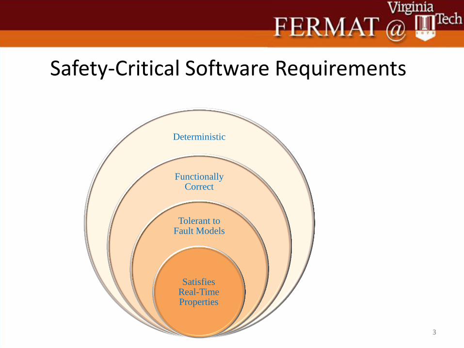
Safety-Critical Software Requirements
3
Deterministic
Functionally Correct
Tolerant to Fault Models
Satisfies Real-Time Properties
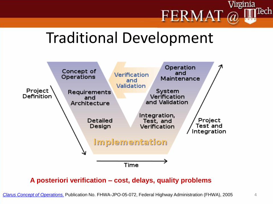
Traditional Development
4 Clarus Concept of Operations. Publication No. FHWA-JPO-05-072, Federal Highway Administration (FHWA), 2005
A posteriori verification – cost, delays, quality problems
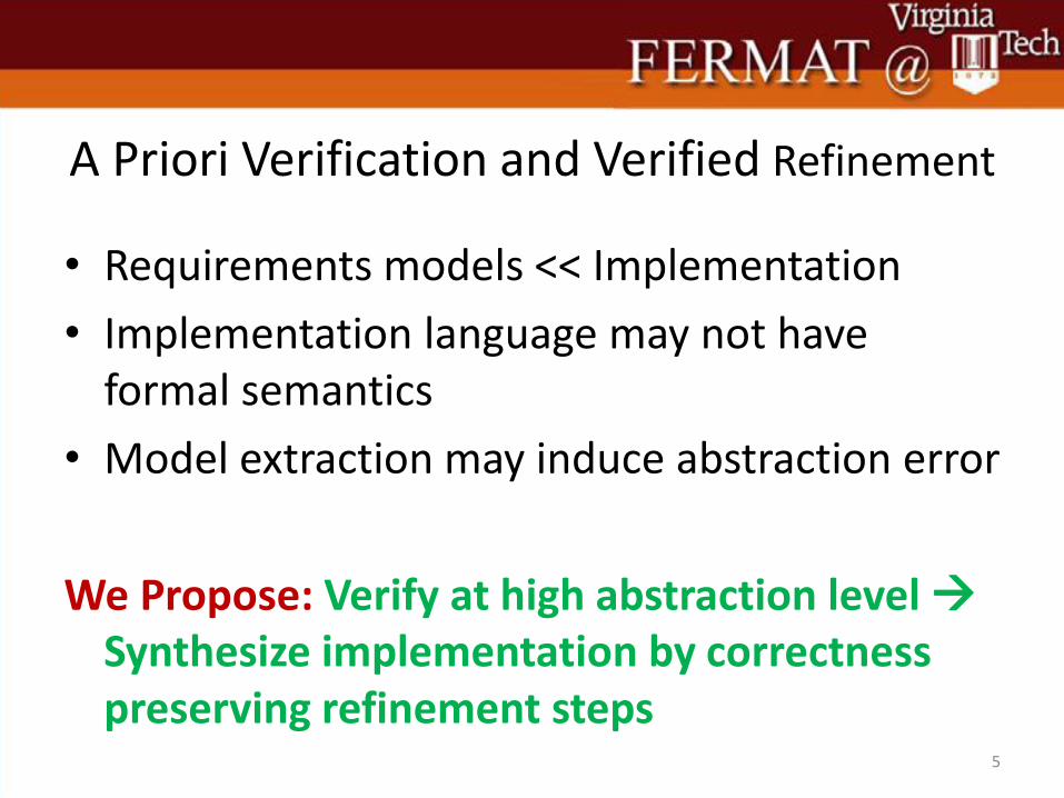
A Priori Verification and Verified Refinement
• Requirements models << Implementation
• Implementation language may not have formal semantics
• Model extraction may induce abstraction error
We Propose: Verify at high abstraction level Synthesize implementation by correctness preserving refinement steps
5
Correct-by-Construction Synthesis
• A Modeling Language
– needed to capture intended computation and communications
– Must be at a high enough abstraction level
– must have formal semantics
– must be verifiable using formal techniques
– refinements towards implementation must be provably correctness preserving steps
6
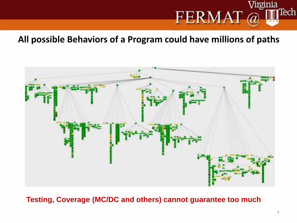
All possible Behaviors of a Program could have millions of paths
7
Testing, Coverage (MC/DC and others) cannot guarantee too much
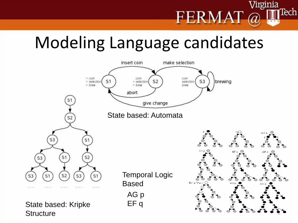
Modeling Language candidates
8
State based: Kripke
Structure
State based: Automata
Temporal Logic
Based
AG p
EF q
Requirements Models • These usually
– Are highest level
– Abstracts away implementation constraints
– Abstract behavior may be nondeterministic
– All behaviors possible in the requirements model may not be implemented based on additional constraints
– Correctness of implementation = set of behaviors of the spec is a super set of behaviors of the implementation
9
What level of Abstraction is Given?
• What if control engineer already gave me an algorithm for control?
• What if O/S designer already has a detailed algorithm in a pseudo notation
• What if the data path is already given
• Then implementation behavior must match the abstract behavior
• Some cases, it can be a subset 10
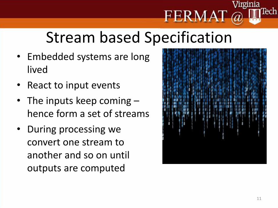
Stream based Specification • Embedded systems are long
lived
• React to input events
• The inputs keep coming – hence form a set of streams
• During processing we convert one stream to another and so on until outputs are computed
11
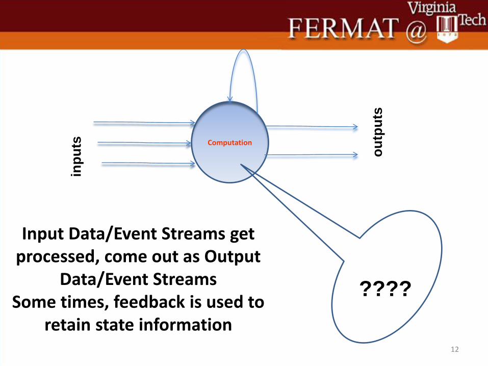
Input Data/Event Streams get processed, come out as Output
Data/Event Streams Some times, feedback is used to
retain state information 12
Computation
inp
uts
ou
tpu
ts
????
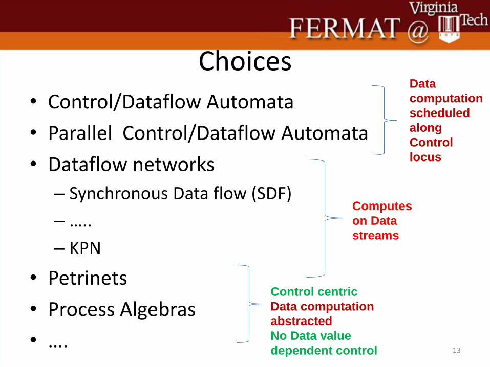
Choices
• Control/Dataflow Automata
• Parallel Control/Dataflow Automata
• Dataflow networks
– Synchronous Data flow (SDF)
– …..
– KPN
• Petrinets
• Process Algebras
• ….
13
Computes
on Data
streams
Data
computation
scheduled
along
Control
locus
Control centric
Data computation
abstracted
No Data value
dependent control
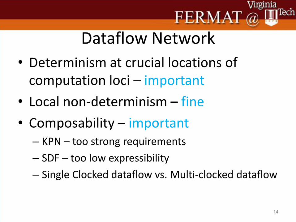
Dataflow Network
• Determinism at crucial locations of computation loci – important
• Local non-determinism – fine
• Composability – important – KPN – too strong requirements
– SDF – too low expressibility
– Single Clocked dataflow vs. Multi-clocked dataflow
14
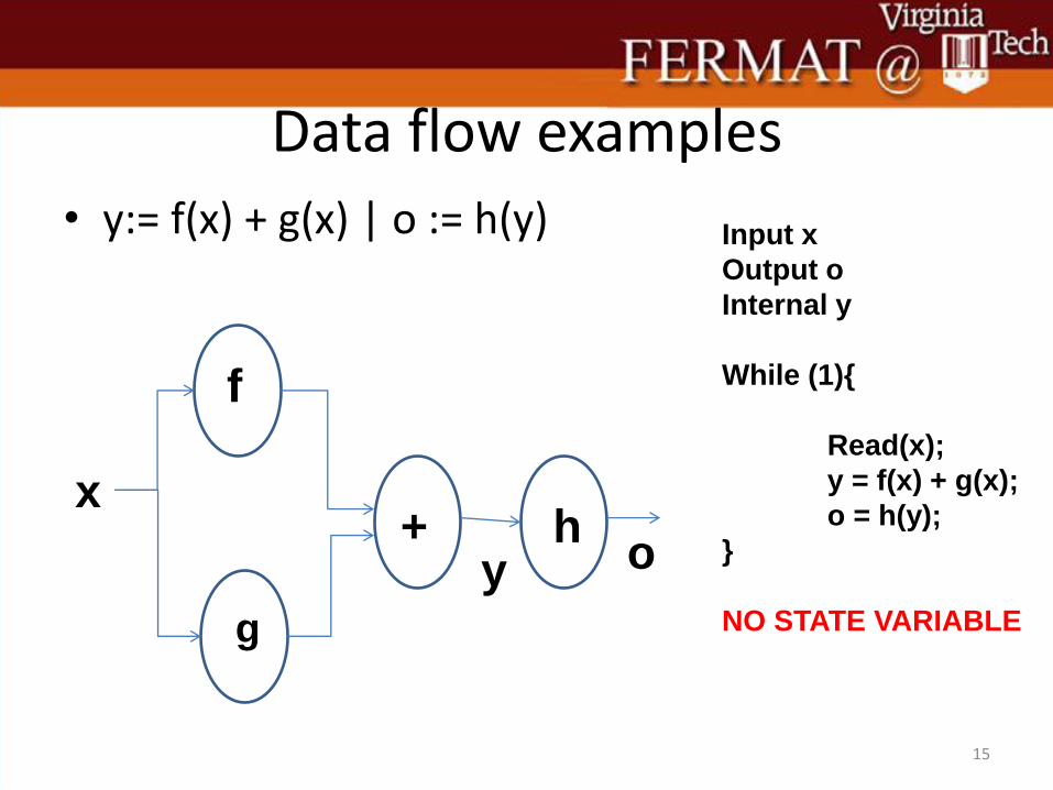
Data flow examples
• y:= f(x) + g(x) | o := h(y)
15
f
g
+ h x
y o
Input x
Output o
Internal y
While (1){
Read(x);
y = f(x) + g(x);
o = h(y);
}
NO STATE VARIABLE
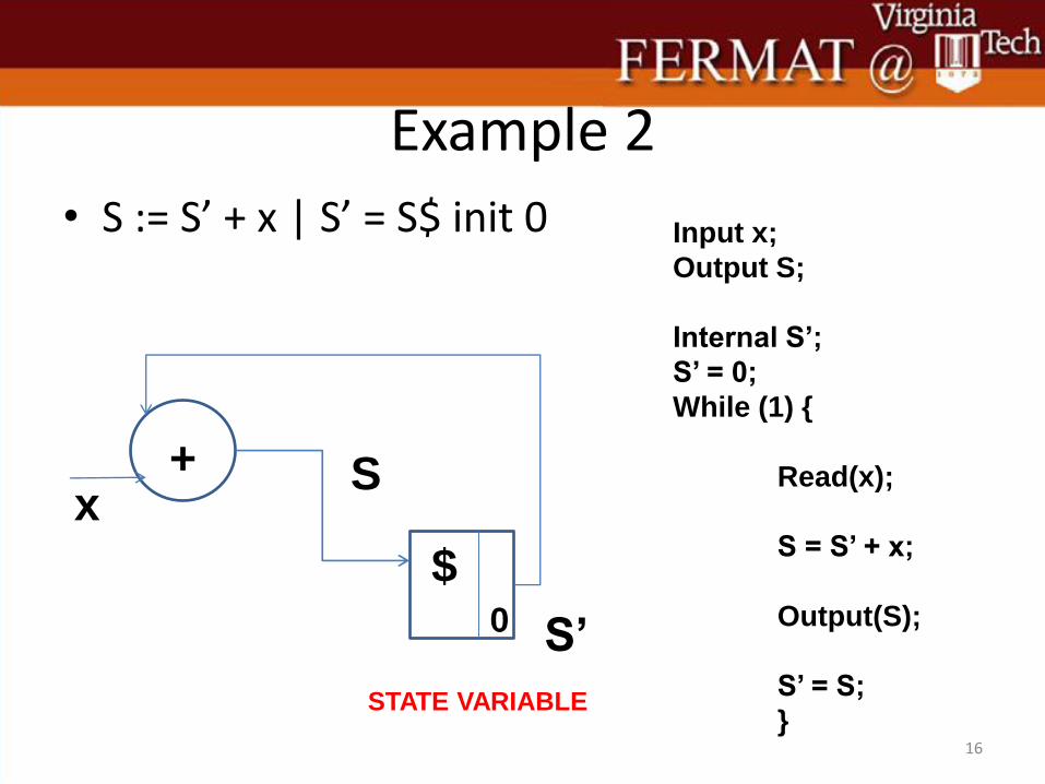
Example 2
• S := S’ + x | S’ = S$ init 0
16
+
$ 0
x S
S’
Input x;
Output S;
Internal S’;
S’ = 0;
While (1) {
Read(x);
S = S’ + x;
Output(S);
S’ = S;
}
STATE VARIABLE
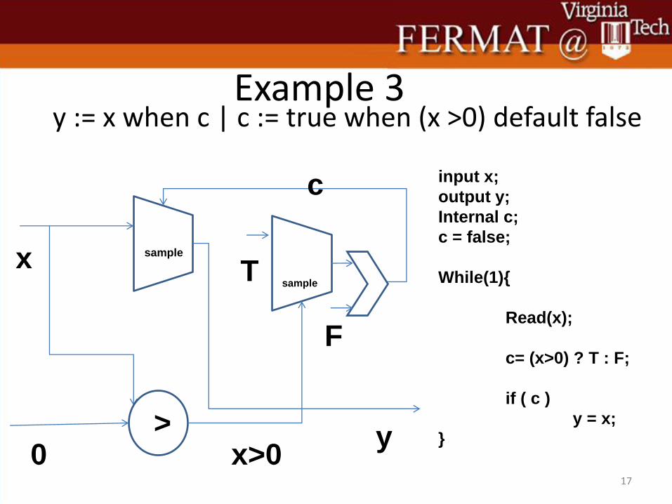
Example 3 y := x when c | c := true when (x >0) default false
17
input x;
output y;
Internal c;
c = false;
While(1){
Read(x);
c= (x>0) ? T : F;
if ( c )
y = x;
}
x
0 > y
x>0
c
F
sample sample
T
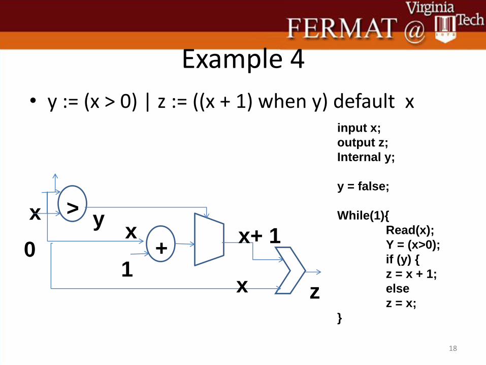
Example 4
• y := (x > 0) | z := ((x + 1) when y) default x
18
x >
0
1 +
x
x
x+ 1
z
y
input x;
output z;
Internal y;
y = false;
While(1){
Read(x);
Y = (x>0);
if (y) {
z = x + 1;
else
z = x;
}
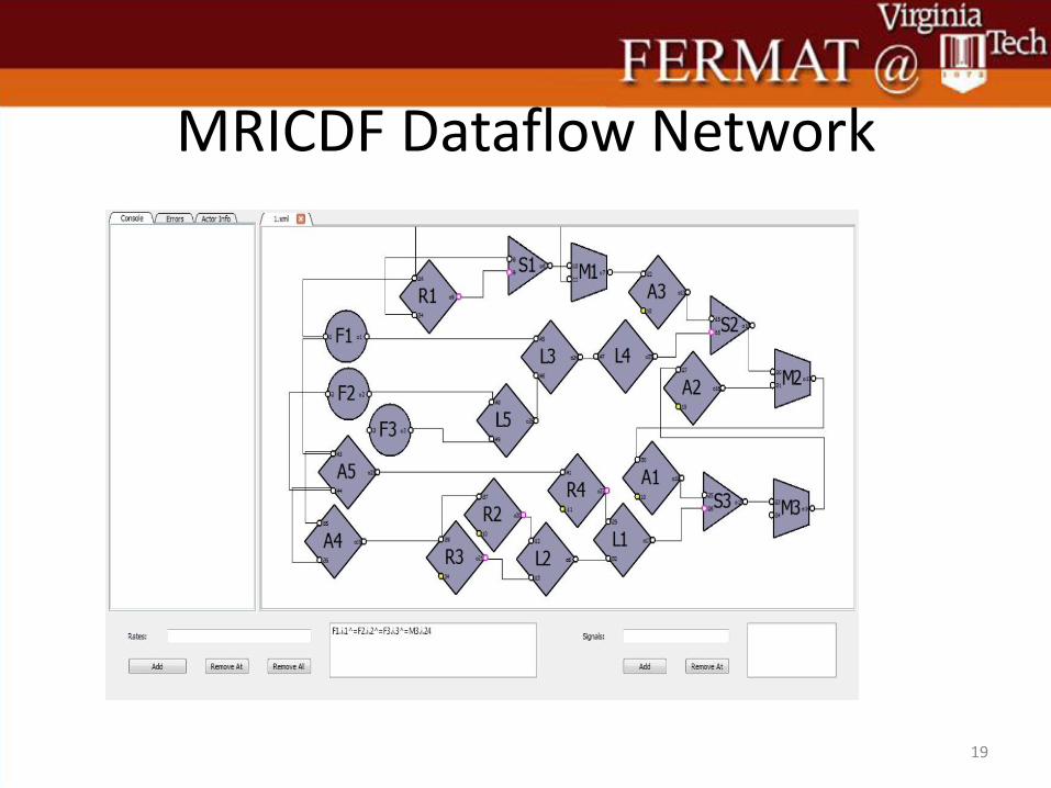
MRICDF Dataflow Network
19
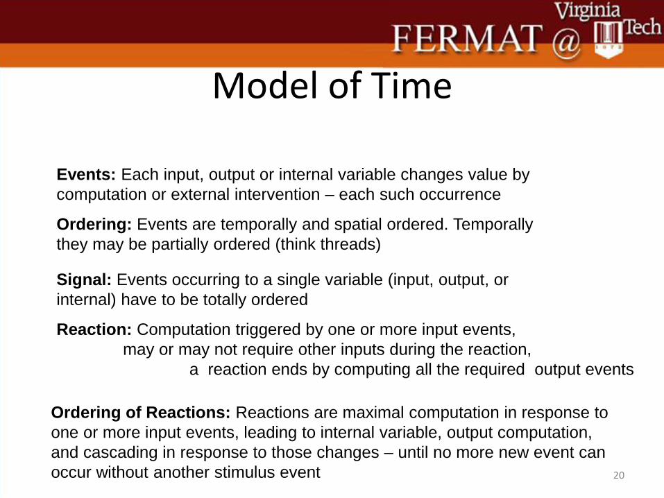
Model of Time
20
Reaction: Computation triggered by one or more input events,
may or may not require other inputs during the reaction,
a reaction ends by computing all the required output events
Events: Each input, output or internal variable changes value by
computation or external intervention – each such occurrence
Ordering: Events are temporally and spatial ordered. Temporally
they may be partially ordered (think threads)
Signal: Events occurring to a single variable (input, output, or
internal) have to be totally ordered
Ordering of Reactions: Reactions are maximal computation in response to
one or more input events, leading to internal variable, output computation,
and cascading in response to those changes – until no more new event can
occur without another stimulus event
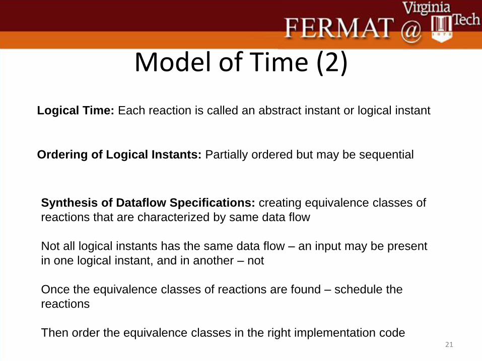
Model of Time (2)
21
Logical Time: Each reaction is called an abstract instant or logical instant
Ordering of Logical Instants: Partially ordered but may be sequential
Synthesis of Dataflow Specifications: creating equivalence classes of
reactions that are characterized by same data flow
Not all logical instants has the same data flow – an input may be present
in one logical instant, and in another – not
Once the equivalence classes of reactions are found – schedule the
reactions
Then order the equivalence classes in the right implementation code
What is MRICDF? • Multi-Rate Instantaneous Communication
Data Flow
• A Visual Language (with a textual substitute) to express a computation over concurrent streams of data
• A stream of data/events –> a totally ordered set of events
• Why care about streams of Data?
22
Examples
23
f
g
+ h x
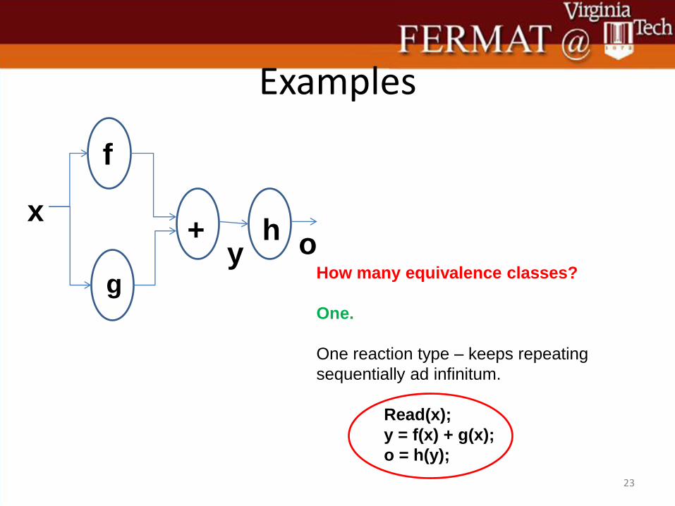
y o How many equivalence classes?
One.
One reaction type – keeps repeating
sequentially ad infinitum.
Read(x);
y = f(x) + g(x);
o = h(y);

Example 2
24
+
$ 0
x S
S’
How many equivalence classes?
One.
One reaction type – keeps repeating
sequentially ad infinitum.
Read(x);
S = S’ + x;
Output(S);
S’ = S;
Example 3
25
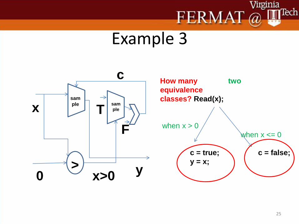
How many
equivalence
classes? Read(x);
when x > 0
c = true;
y = x;
two
when x <= 0
c = false;
x
0 > y x>0
c
F
sam
ple sam
ple T
Example 3.1
26
x
0
y
c
T
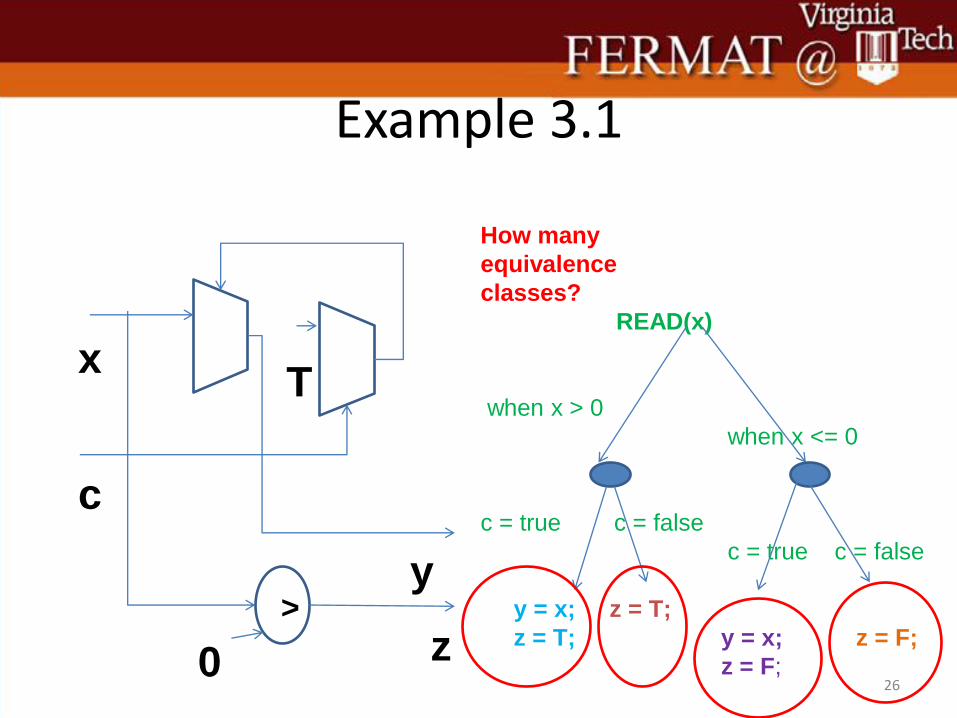
How many
equivalence
classes?
READ(x)
when x > 0
c = true c = false
y = x; z = T;
z = T;
when x <= 0
c = true c = false
y = x; z = F;
z = F; z
>
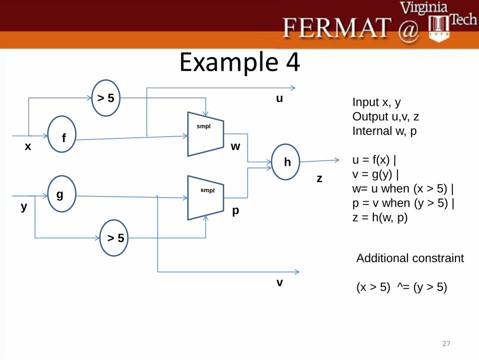
Example 4
27
f
g
x
y
> 5
> 5
z
h
smpl
u
v
w
p
Input x, y
Output u,v, z
Internal w, p
u = f(x) |
v = g(y) |
w= u when (x > 5) |
p = v when (y > 5) |
z = h(w, p)
Additional constraint
(x > 5) ^= (y > 5)

Synchronization = Stretch an Instant
28
x y u v w p z x>5
y >5
1 f(1) F
1 g(1) F
1 f(1) F
6 1 f(6) g(1) f(6) T F
1 g(1) F
8 f(8) f(8) T
1 9 f(1) g(9) g(9) h(f(6), g(9)
F T
8 f(8)
1 f(1)
f(8) T
F

Example 4 requires multithreading
29
Thread 1
while (1){
b = false;
Read(x);
u = f(x);
If (x> 5){
b = true;
wait(e1);}
}
}
Thread 2
while (1){
c = false;
Read(y);
v = g(y);
If (y > 5) {
c = true;
wait(e2);
}
}
Thread 3
while (1){
while (b ! = true || c != true) ;
z = h(u,v);
notify(e1,e2);
}
u v
b c

Finding those Reaction Equivalence Classes
• Clock Calculus
– Create the order in which inputs must be read or outputs must be computed or internal variables must be computed
– Each leaf of the resulting tree will provide the different possible equivalence classes of reactions
– Within each leaf the computation is ordered based on data dependencies
• Must check there is not cyclic dependencies (causality)
– The over all schedule is read off the clock tree, and the leafs
30
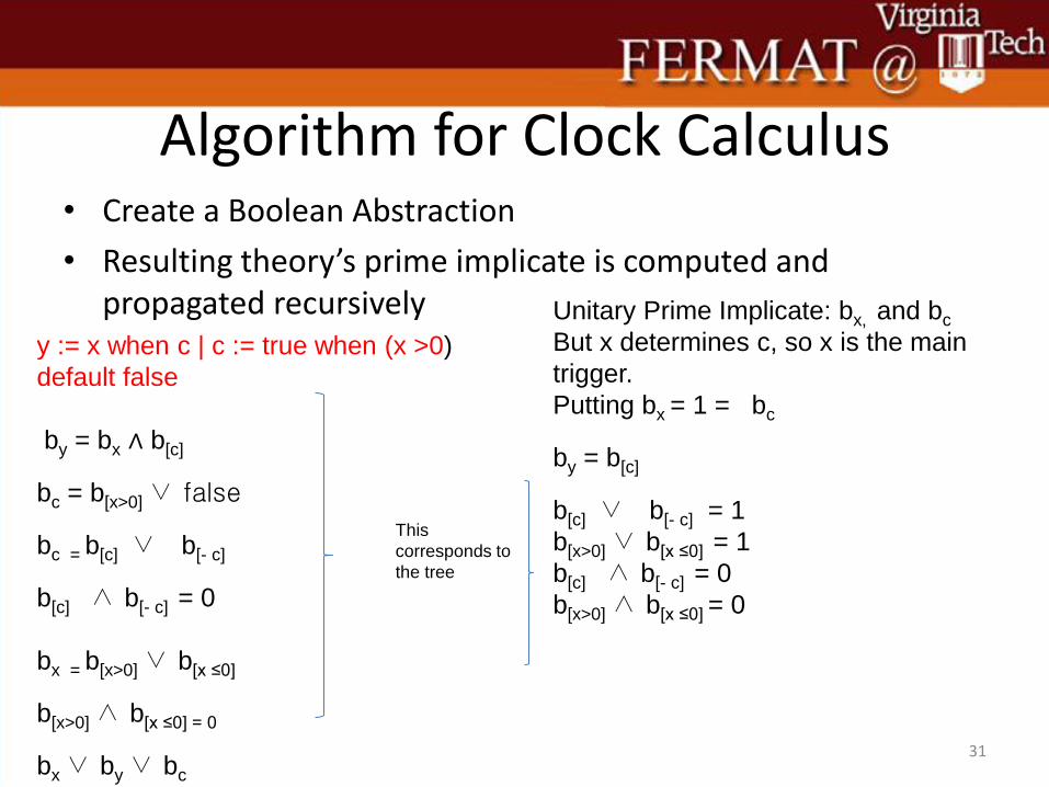
Algorithm for Clock Calculus • Create a Boolean Abstraction
• Resulting theory’s prime implicate is computed and propagated recursively
31
y := x when c | c := true when (x >0)
default false
by = bx ∧ b[c]
bc = b[x>0] ∨ false
bc = b[c] ∨ b[- c]
b[c] ∧ b[- c] = 0
bx = b[x>0] ∨ b[x ≤0]
b[x>0] ∧ b[x ≤0] = 0
bx ∨ by ∨ bc
Unitary Prime Implicate: bx, and bc
But x determines c, so x is the main
trigger.
Putting bx = 1 = bc
by = b[c]
b[c] ∨ b[- c] = 1
b[x>0] ∨ b[x ≤0] = 1
b[c] ∧ b[- c] = 0
b[x>0] ∧ b[x ≤0] = 0
This
corresponds to
the tree
32
33
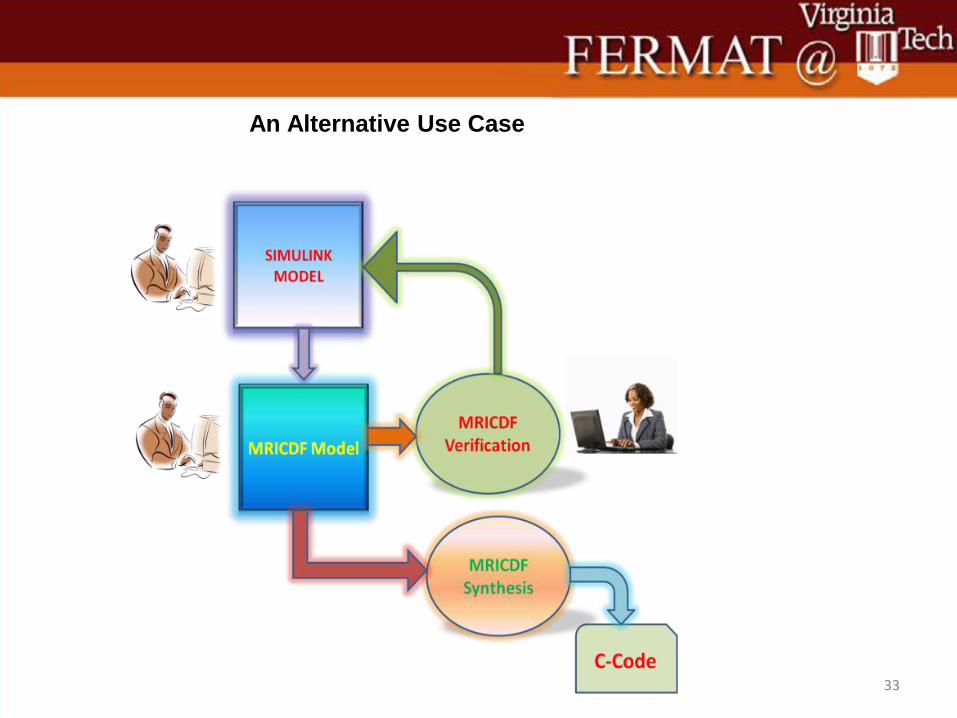
An Alternative Use Case
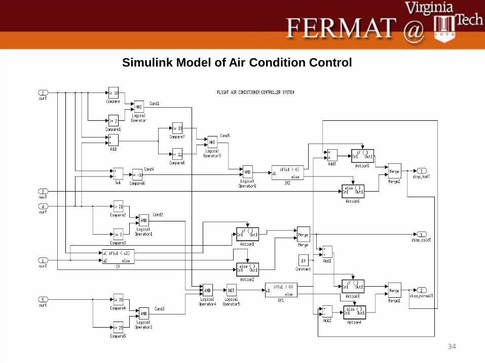
34
Simulink Model of Air Condition Control
35
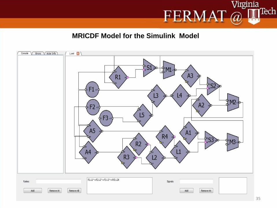
MRICDF Model for the Simulink Model

36
MRICDF to C Code Synthesis Flow
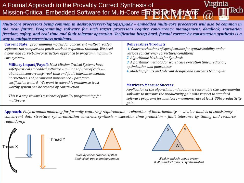
Current State: programming models for concurrent multi-threaded software too complex and patch work on sequential thinking. We need a new and correct-by-construction approach to programming multi-core systems.
Approach: Polychronous modeling for formally capturing requirements – relaxation of linearlizability -- weaker models of consistency – concurrent data structure, synchronization construct synthesis – execution time prediction – fault tolerance by timing and resource redundancy.
Military Impact/Payoff: Most Mission Critical Systems have safety-critical embedded software – millions of lines of code --- abundant concurrency- real-time and fault-tolerant execution. Correctness is of paramount importance – post facto verification is hard. We want to solve this problem so trust worthy system can be created by construction. This is a step towards a science of parallel programming for multi-core.
Deliverables/Products 1. Characterizations of specifications for synthesizability under various concurrency correctness conditions 2. Algorithmic Methods for Synthesis 3. Algorithmic methods for worst case execution time prediction, optimization and guarantees 4. Modeling faults and tolerant designs and synthesis techniques
Metrics to Measure Success: Application of the algorithms and tools on a reasonable size experimental software to measure the productivity gain with respect to standard software programs for multicore -- demonstrate at least 30% productivity gain.
Multi-core processors being common in desktop/server/laptops/ipad2 – embedded multi-core processors will also be common in the near future. Programming software for such target processors require concurrency management, deadlock, starvation freedom, safety, and real-time and fault-tolerant operation. Verification being hard, formal correct-by-construction synthesis is a way to mitigate correctness problems.
A Formal Approach to the Provably Correct Synthesis of
Mission-Critical Embedded Software for Multi-Core Embedded Platforms
Thread X
Thread Y
X
Y
W
Weakly endochronous system
If W is endochronous, synthesizable!
X
Y
Weakly endochronous system
Each clock tree is endochronous