Corporate Network (Security Aspects)
75
Degree Project Nikolay Nikolov 2010-10-12 Subject: Computer Systems and Networks Level: Master Course code: 4DV01E Corporate Network (Security Aspects)
Transcript of Corporate Network (Security Aspects)

Degree Project
Nikolay Nikolov 2010-10-12 Subject: Computer Systems and Networks Level: Master Course code: 4DV01E
Corporate Network (Security Aspects)

ii
Abstract
Every corporation using IT technologies needs a good and carefully secured network design. The IT security is a key factor of a normal functional of the whole corporation and all its sections. There different methods and concepts for providing different level of IT security. Some of them are very important and should be implemented in every corporate network.
There are a lot of services providing inside and outside the corporation network. Increasing the number of services like web services, mail services, file services and other, the number of eventual security issues is rising. The security methods of each of provided services are different and it is required a professional with deep knowledge about this service functionality if it is needed to be good applied.
Operation system and application hardering are methods which are not so hard for applying, like configuring proxy server or firewalls, but they could increase the security drastic. In a combination with simple configured security devices, the results could be very impressive.
Choosing the right methodology and framework of designing a secured network is important part of entire process. With the right methodology designing could be easier and more effective.
Keywords: design examples, e-mail services, web services, dns services, dhcp
services, ldap services, routers, firewalls, hardering, security technologies, RADIUS, OTP, PKI, IDS, ACLs, cryptography.

iii
Contents 1 Introduction .......................................................................................................... 1
1.1 Problem Definition ....................................................................................... 1
1.2 Motivation .................................................................................................... 1 1.3 Method .......................................................................................................... 1 1.4 Restrictions ................................................................................................... 1 1.5 Report structure ............................................................................................ 2
2 Corporate networks .............................................................................................. 3 2.1 What is corporate network? .......................................................................... 3
2.1.1 Edge Network ....................................................................................... 3 2.1.2 Internal Network ................................................................................... 3
2.2 Corporate Security ........................................................................................ 4 3 Services in corporate networks ............................................................................. 5
3.1 E-Mail services ............................................................................................. 5 3.1.1 Basic two tier e-mail design ................................................................. 5 3.1.2 Distributed two tier e-mail design ........................................................ 5
3.2 DNS services ................................................................................................ 6 3.2.1 Single DNS server design ..................................................................... 7
3.2.2 Distributed DNS Design ....................................................................... 7 3.3 HTTP/HTTPS services ................................................................................. 8
3.3.1 Simple Web design ............................................................................... 8 3.3.2 Two-tier Web design ............................................................................ 9 3.3.3 Three-tier Web design .......................................................................... 9
3.4 FTP services ............................................................................................... 10 3.4.1 Active mode ........................................................................................ 10 3.4.2 Passive mode ...................................................................................... 11 3.4.3 Design example .................................................................................. 11
3.5 Instant Messaging services ......................................................................... 11 3.6 DHCP services ............................................................................................ 11 3.7 Directory services ....................................................................................... 12 3.8 RADIUS server .......................................................................................... 12 3.9 ERP server .................................................................................................. 14
4 Security Technologies ........................................................................................ 15 4.1 Identity Technologies ................................................................................. 15
4.1.1 Reusable passwords ............................................................................ 15 4.1.2 RADIUS and TACACS+ ................................................................... 15 4.1.3 OTP ..................................................................................................... 15
4.1.4 PKI ...................................................................................................... 16 4.1.5 Smart cards ......................................................................................... 16 4.1.6 Biometrics ........................................................................................... 16 4.1.7 Identity Technologies Summary ......................................................... 16
4.2 Host and Application Security .................................................................... 17 4.2.1 File system integrity checkers ............................................................ 17
4.2.2 Host firewalls ...................................................................................... 17 4.2.3 Host intrusion detection system .......................................................... 18 4.2.4 Host antivirus ...................................................................................... 18 4.2.5 Host and Application Security Summary ........................................... 18
4.3 Network Firewalls ...................................................................................... 19 4.3.1 Routers with Layer 3/4 stateless ACLs .............................................. 19 4.3.2 Stateful firewalls ................................................................................. 19 4.3.3 Network Firewalls Summary .............................................................. 19

iv
4.4 Content Filtering ......................................................................................... 20 4.4.1 Proxy filtering ..................................................................................... 20 4.4.2 Web filtering ....................................................................................... 20
4.4.3 E-Mail filtering ................................................................................... 20 4.4.4 Content-Filtering Summary ................................................................ 20
4.5 Network Intrusion Detection Systems ........................................................ 21 4.5.1 Signature-based NIDS ........................................................................ 21 4.5.2 Anomaly-Based NIDS ........................................................................ 21
4.5.3 NIDS Summary .................................................................................. 21 4.6 Cryptography .............................................................................................. 22
4.6.1 Layer 2 cryptography.......................................................................... 22 4.6.2 Network cryptography ........................................................................ 22 4.6.3 L5 to L7 cryptography ........................................................................ 22
4.6.4 File system cryptography ................................................................... 22 4.6.5 Cryptography Summary ..................................................................... 22
5 Methods and decisions for corporate network security ...................................... 24 5.1 Demilitarized zones .................................................................................... 24
5.1.1 A Basic Network with a Single Firewall ............................................ 24
5.1.2 Basic Network, Single Firewall and Bastion Host ............................. 25 5.1.3 Traffic flow of Basic Network, Single Firewall and Bastion Host .... 26 5.1.4 A Multitiered Firewall With a DMZ .................................................. 27 5.1.5 DMZ design ........................................................................................ 29 5.1.6 DMZ protocols ................................................................................... 29 5.1.7 DMZs network resources protection methods .................................... 29
5.1.8 What kind of servers we can locate in DMZs .................................... 30 5.2 Device Hardering ........................................................................................ 31
5.2.1 Hardering strategy components .......................................................... 31 5.2.2 Network devices ................................................................................. 32 5.2.3 Host Operating Systems ..................................................................... 33
5.3 Rogue Device Detection ............................................................................. 33 6 Network Design Principle and Methodology ..................................................... 35 7 Network designing .............................................................................................. 37
7.1 Principal Scheme ........................................................................................ 37 7.2 Corporate Edge Security Design ................................................................ 37
7.2.1 Design Requirements .......................................................................... 37 7.2.2 Design Overview ................................................................................ 38 7.2.3 Design Evaluation .............................................................................. 40
7.3 Internal Corporate Network Security Design ............................................. 41 7.3.1 Design Requirements .......................................................................... 41 7.3.2 Design Overview ................................................................................ 41 7.3.3 Design Evaluation .............................................................................. 45
8 Network equipment ............................................................................................ 47 8.1 Firewalls ..................................................................................................... 47
8.1.1 Edge Network ..................................................................................... 47 8.1.2 Internal Network ................................................................................. 47
8.2 Routers ........................................................................................................ 51 8.3 Switches ...................................................................................................... 53 8.4 Intrusion detection systems ........................................................................ 54 8.5 Servers ........................................................................................................ 54
9 Desktop computers organization in different corporate sections ....................... 56 10 Final network design proposed models .......................................................... 57

v
11 Testing and Security decisions ....................................................................... 58 11.1 Virtual testing environment ........................................................................ 58 11.2 Test result and analyzing ............................................................................ 58
11.2.1 Server testing ...................................................................................... 59 11.2.2 Firewall testing ................................................................................... 59
12 Conclusions and future work .......................................................................... 60 References .................................................................................................................. 61 Appendix A ................................................................................................................ 62
Appendix A.1 ......................................................................................................... 62 Appendix A.2 ......................................................................................................... 64 Appendix A.3 ......................................................................................................... 66

vi
List of abbreviations
DMZ- Demilitarized Zone WAN- Wide Area Network VPN- Virtual Private Network DNS- Domain Name Service SNMP- Simple Network Management Protocol AAA- Authentication, Authorization, and Accounting SMTP- Simple Message Transfer Protocol POP3- Post Office Protocol, version 3 IMAP- Internet Message Access Protocol DoS- Denial-of-service DNSSEC- DNS Security Extensions IETF- Internet Engineering Task Force VLANs- Virtual Local Area Network SFTP- Secured File Transfer Protocol FTP- file transfer protocol SSH- Secured Shell IM- instant messaging DHCP- Dynamic Host Configuration Protocol MAC- Media Access Control LDAP- Lightweight directory access protocol RADIUS- Remote Authentication Dial In User Service TACACS+- Terminal Access Controller Access-Control System Plus OTP- one-time password PIN- Personal Indentify PKI- Public Key Infrastructure CA- certificate authority HIDS- Host Intrusion Detection Systems TCP- Transmission Control Protocol UDP- User Datagram Protocol URL- Uniform Resource Locator HTTP- Hypertext Transfer Protocol NIDS- Network Intrusion Detection System WEP- Wired Equivalent Privacy IEEE- Institute of Electrical and Electronics Engineers IPSec- IP security SSL- Secure Sockets Layer ICMP- Internet Control Message Protocol IOS- Internetwork Operating System OS- Operation System CEO- Chief executive officer CIO- Chief Information officer CTO- Chief Technology officer CPU- Central Processor Unit

vii
List of figures and tables
Figures: Figure 3.1 Basic two tier e-mail design ..................................................................... 5 Figure 3.2 Distributed two tier e-mail design ............................................................. 6 Figure 3.3 Single server design example ..................................................................... 7 Figure 3.4 Distributed DNS server design .................................................................. 8 Figure 3.5 Simple network design .............................................................................. 8 Figure 3.6 Two-Tire web design ................................................................................ 9 Figure 3.7 Three-tier Web design with two firewalls ................................................ 10 Figure 3.8 Three-tier Web design with three firewalls .............................................. 10
Figure 3.9 FTP server design ..................................................................................... 11 Figure 3.10 RADIUS client-server communication model ....................................... 13 Figure 3.11 Radius server locating ............................................................................ 14 Figure 3.12 ERP Server placement example ............................................................. 14 Figure 5.1 A Basic Network with a Single Firewall ................................................. 24
Figure 5.2 Traffic flow of a Basic Network with a Single Firewall ......................... 25 Figure 5.3 Basic Network, Single Firewall and Bastion Host .................................. 26 Figure 5.4 Traffic flow of Basic Network, Single Firewall and Bastion Host ......... 26 Figure 5.5 A Basic Firewall With a DMZ ................................................................ 27 Figure 5.6 Traffic flow of Basic Firewall with a DMZ ............................................ 27 Figure 5.7 A Multitiered Firewall With a DMZ ....................................................... 28 Figure 5.8 Traffic flow a Multitiered Firewall With a DMZ .................................... 28
Figure 5.9 A Basic Screened Subnet ........................................................................ 30 Figure 6.1 Stages of the PDIOO Process .................................................................. 35 Figure 7.1 Proposed principle design ........................................................................ 37 Figure 7.2 Proposed Edge network design ................................................................ 38 Figure 7.3 Proposed internal network design ............................................................ 42 Figure 9.1 Desktop organization with logical separating .......................................... 56 Figure 10.1 Proposed network edge design ............................................................... 57
Figure 10.2 Proposed internal network design .......................................................... 57 Figure A1.0.1 Creating a VM options - select OS ..................................................... 62 Figure A1.0.2 Creating a VM options - hardware customization .............................. 62 Figure A1.0.3 VM team - network connection configuration ................................... 63 Figure A1.0.4 VM team - LAN segments configuration ........................................... 63
Figure A2.0.5 GNS3- Adding real IOS ..................................................................... 64 Figure A2.0.6 GNS3- Added device options ............................................................. 64
FigureA2.0.7 GNS3 - Connection Router-Cloud ...................................................... 65 FigureA2.0.8 GNS3 - Adding expansion cards on a device ...................................... 65 Figure A3.9 Nessus3 Options .................................................................................... 66 Figure A3.0.10 Nessus3 Plug-in selection ................................................................. 66

viii
Tables: Table 4.1 Identity technologies summary ................................................................. 17 Table 4.2 Host and Application Security Summary ................................................ 18 Table 4.3 Network Firewalls Summary .................................................................... 19 Table 4.4 Content-Filtering Summary ...................................................................... 20 Table 4.5 NIDS Summary ........................................................................................ 21 Table 4.6 Cryptography Summary ........................................................................... 23 Table 7.1 Proposed Edge Design Attack Resistance ................................................. 41 Table 7.2 Design Evaluation ...................................................................................... 46 Table 8.1 Cisco ASA series specifications Part 1 ...................................................... 49 Table 8.2 Cisco ASA series specifications Part 2 ...................................................... 50 Table 8.3 Cisco 3900 Series Function Details ........................................................... 51
Table 8.4 Cisco 2900 Series Function Details ........................................................... 52

1
1 Introduction
Designing network security is important part of the designing of the entire network. To be good secured one network it is needed all the requirements to be detailed before the designing begins.
In this project we will describe one designing method of a secured corporate computer network. We will set an example requirements for services provided inside and outside the network and we will discuss the some methods for securing them. We will use different hardering strategies and rogue detection. We will look at the different type of Demilitarized Zones (DMZ) designs and will use one or more of them. Another main point from the project is describing different security technologies used widely in almost all security devices and methods.
1.1 Problem Definition The proper combination of technologies, methods and equipment is the main goal of this project, but which one to choose is the main question. Our main task will be:
• Choosing the proper design for the servers • Choosing security technologies of use • Choosing methods for security increasing • Choosing equipment, which satisfy our requirements
The final result should be a design network, with chosen services, servers and
network equipment. We should choose the solutions which are with bigger security capabilities and to satisfy the requirements of the number of users.
1.2 Motivation The network security is a section from the IT security, which is very important for functionality of the whole corporation. One successful attack in one corporate network could make a lot of damages like stealing confidential information, spying all users, manipulating some information and etc.
The network security should be implemented in the beginning of the network design, and we will try to it in this project.
1.3 Method We will choose a framework (technologies, methods and designs), and we will implement all these parts in one project implemented in a virtual environment. This environment is based on two basic software products – VMware workstation and GNS3. VMware workstation we will use for simulating the different type of servers and GNS3 we will use for simulating the network devices- firewalls, routers, switches and IDS.
1.4 Restrictions We will design a network which should satisfy the requirements of a mid-size corporate network (up to 1000 users). The different type of services which we will provide inside and outside the network will be web, e-mail, dns and ldap. We will think about ERP systems, but we will only set the location of this type of servers in our network, and we will not discuss details about their configuration.

2
1.5 Report structure The project is contains 12 main chapters, 1 appendix with 3 sub appendixes. The whole project is 60 pages. Chapter 1 introduces us in the project and describes the problem definition, motivation, methods, restrictions and report structure. Chapter 2 gives us information about corporate networks and corporate network security. Chapter 3 describes some of the services which should be included in one corporate network. Some of them are e-mail, web, dns, ftp, dhcp. Chapter 4 describes different security technologies and methods. Some of them are identifying technologies, network firewalls and content filtering. Chapter 5 describes methods and decisions for corporate network security improving. There is information about demilitarized zones, device hardering and rogue device detection. Chapter 6 describes the network design principle and methodology used in the project. Chapter 7 describes the designed network and its parts. Chapter 8 describes the network device choosing process. Chapter 9 describes the desktop computer organization in the designed corporate network. Chapter 10 shows the final network design shames and some description. Chapter 11 describes the testing of the designed network and shows some of the results. Chapter 12 describes the conclusions and future work of the project.

3
2 Corporate networks
In this chapter we will look at some definitions and aspects of the corporate networks.
2.1 What is corporate network? In most cases entire corporate network can be separated in two networks. One of them is Edge Network and the other one is Internal Network. One corporate network can have multiple edges, depending on how many sites we have. A general rule, the edge of your network is the part that connects to other networks over some kind of WAN (Wide Area Network). The internal network connects to the edge through one or more connections. Placed within most internal networks are the following components - Client hosts, Department servers, Central servers, Management devices and Switched/routed network infrastructure.
2.1.1 Edge Network Some of the corporate networks could have more than one edge network. The number of the edge networks our corporate needs is depending only from the services which we are providing inside and outside the entire corporation. The main components of the edge networks are:
• Private WAN links- for providing and receiving specific services • Internet WAN links- for receiving internet services and internet access • Public servers- servers for providing services which are accessible from the
outside networks and from the internal network. • Site-to-site VPN (Virtual Private Network) tunnels- for connecting branch
offices • Remote user VPN tunnels- for connecting travelling and remote users to the
corporate resources like ERP systems and other services. • Public Switched Telephone Network (PSTN) dial-up- another way for
connecting travelling and remote users. It is possible and to connect remote branch office through it, too.
• Extranet connections- for backups and to connect some corporate partners. • E-commerce networks- these networks are only for corporations providing e-
commerce services. They could be connected to the edge network though different type of links, but should be separated from the another part of the network with using additional router or firewall.
2.1.2 Internal Network This part of the network is connected to the edge network through one or more network links. In this part are placed all corporate servers for internal services and all desktop systems except these which are connecting to the network through VPN or some other method for remote connection. All main parts of the internal corporate networks are:
• Client hosts- end-user computers, workstations, and so on • Department servers- servers and applications which are limited for some of the
users in the internal network • Central servers- Servers and applications accessible by all users (e-mail server,
Domain Name Service (DNS) server , Web server, file server, and others) • Management devices- all devices which have features for monitoring of the
different types of services and protocols which we are using. Most of these devices are using Simple Network Management Protocol (SNMP) or other specific security event monitors.

4
• Switched/routed network infrastructure- all routers, all Ethernet switches, IDS, Firewalls and other infrastructure devices that enables communication between the internal network, the edge network and external networks
2.2 Corporate Security IT security is the protection of systems, resources, and information from unintended and unauthorized access or misuse. A review of the most publicized attacks over the years indicates that network security plays an important role in achieving the goals of the preceding definition.
In addition, IT applications, and lately, Internet applications, are becoming more and more mission-critical to organizations. The complexity of these applications, along with the operating system and computing platforms that they run on, makes them vulnerable to attacks. Because the application often controls access to the information, security of the applications is also important.
The network provides the conduit for users to interact with the application and thereby the data. It follows that securing the network is imperative as the first line of defense in IT security. Without a secure network, applications and information can be subjected to continuous salvos from the multitude of attackers.
In addition to today's attacks, the network security engineer is concerned about the vulnerabilities of the latest network technologies. In the last few years, IPSec virtual private networks (VPNs) have been touted as a more cost effective and flexible means of connectivity. Certainly, the encryption and authentication mechanisms specified in IPSec provide a strong technique for protecting the confidentiality of the transported information, but the increase in the number of connections to the Internet expands the exposure of the network.[13]
Likewise, wirelesses LANs have introduced a whole new set of vulnerabilities. The possibility of unauthorized users gaining access to the corporate network is no longer limited to physical connectivity; it can be done over the air. Attackers need only be in the proximity of your corporate location to get access to the transmission medium.
These are only two of the many new technologies being introduced in corporate networks. To maintain the security posture of a network, the design engineer must simultaneously integrate security technologies, best practices and good hardering strategies as each new technology is introduced into the network.

5
3 Services in corporate networks
In this chapter we will examine the services, some of them we will include in our secured corporate network design. We will show some examples of network designs of these services and we will discuss some methods for security improvement.
3.1 E-Mail services When we are trying to provide secured e-mail services we must think on two main aspects- separating incoming from outgoing mail servers and providing quality antivirus scanning. Placing a central antivirus server in our datacenter is better decision, then to installing mail antivirus software on each of user’s computers, because of management updating points of view. Here are two different designs of mail servers’ network infrastructures:
3.1.1 Basic two tier e-mail design Figure 3.1 shows a design with internal and external mail servers. This design is good choice for midsize and small organization, which want to have own mail servers.
Figure 3.1 Basic two tier e-mail design [1]
The outside server can send mails only to external Simple Message Transfer Protocol
(SMTP) server and it can deliver messages to the internal mail server. This external server is using and when we are trying to send mails from internal network to the internet. We can block all other SMTP traffic, expect this from the external server and in this way we guarantee that mails will be send only from the real corporative servers. The internal mail server has two main functions- to route messages inside the internal network and to send messages to the external SMTP server, and allowing internal users to get their mail via POP3 (Post Office Protocol, version 3) or IMAP (Internet Message Access Protocol), protocols. We can add an antivirus server to this design or to install antivirus software on located servers. [1]
3.1.2 Distributed two tier e-mail design Figure 3.2 shows a distributed e-mail design. This design is more expensive for realization and is used by large corporations. The main differences with the shown design in previous point are:

6
• Separating internal incoming servers (POP3 and IMAP) from the outgoing server (SMTP), which deliver more scalability of the whole mail system.
• Placing dedicated server for antivirus scanning.
Figure 3.2 Distributed two tier e-mail design [1]
The antivirus server is the most important benefit of this design. It scans messages
from and to internal network. The function of internal mail server is allowing internal users to get their mail via POP3 or IMAP protocols. External SMTP server and outside SMTP server keep the same functions like in previous design. [1]
3.2 DNS services The principle of placing of the DNS servers is similar the mail servers. It is good to separate internal network DNS and external DNS servers.
Here are some good practices for designing our DNS network infrastructure: [1] • All DNS servers must be more separated- we need at least two DNS servers
(master and slave), and it is very important to put them in different locations, because in this way they have greater protection for Denial-of-service (DoS) attacks. Under separation we mean that the servers must be in different network segments and not to share one internet connection.
• More Authoritative DNS Server- with this practice we take one more protection for DoS attacks, because even we separate our DNS servers, an attacker can try to attack our authoritative DNS server and in this way can stop or manipulate its working.
• Our External DNS Servers must be Non-recursive Responders only- there are two types of DNS queries- recursive and non-recursive. When we use recursive queries to a DNS server, it answers us even if the server needs to communicate with other servers. Non-recursive query make DNS answer only information, which already have, and it can not communicate with other servers looking for answers of unknown queries
• Protect our Internal DNS servers- if we will use only non-recursive external DNS server, we must provide internal server answering our users’ recursive queries. The easier way to this is to use internal server for internal DNS data and separate forwarders for information outside the corporation.

7
• Limiting Zone Transfers to Authorized DNS Servers- zone transfers are using by slave name servers to get information from master name servers. This type of transfers must be blocked and used only when it is needed.
Here are the two different examples of placing DNS server in our network
infrastructure:
3.2.1 Single DNS server design Figure 3.3 shows the simplest DNS design, because we are using only one DNS server. Outside DNS server is not part from the network and usually it is ISP’s DNS server. The main disadvantage of this design is that security level is very low. If we need some extra security we can use some of the DNS application software security features.
Figure 3.3 Single server design example [1]
The firewall in this design can protect DNS server with blocking all ports expect
DNS port (UDP 53). This design is good to be used only for small networks. [1]
3.2.2 Distributed DNS Design Figure 3.4 shows a distributed DNS design example. This design is good for midsize and large corporations. The number of servers depends from the requirements. The high level of security is reached with separating of DNS servers.

8
Figure 3.4 Distributed DNS server design [1]
This design requires placing a Master DNS server in this part of the network. We
increase security of this service by using layer separation of DNS architectures. When an internal computer makes a request to its DNS server, it forward all queries that it can not resolve to group of servers, which have permission to make queries outside the network. If we need we can use DNS Security Extensions (DNSSEC) standard of the Internet Engineering Task Force (IETF). [1]
3.3 HTTP/HTTPS services The security of this type service is depending on the application we use. Each application has different method to improve its security. The network design and web servers placing are important part of improving the service’s security with providing load-balancing options. Here are the available network designs providing web services:
3.3.1 Simple Web design Figure 3.5 shows the simplest network design with web server. This server is connected to the third port of the firewall between internal network and Internet. Here we can use this firewall to block all ports on the web server’s port and to allow only application port (for example port TCP 80).
Figure 3.5 Simple network design [1]

9
3.3.2 Two-tier Web design If we need to provide a services with dynamic content, we will need application and in most cases database server. Figure 3.6 shows a design with using separation between main web server and the application and database server. It will be hard if someone to steal some information or to do some damage on the database or the application server in this situation, because only web server can access the application and database server. We cannot put the server in one network segment, because this will not stop the attacker to attack and second server if he can attack the first. Using private Virtual Local Area Network (VLANs) is not good decision, too, because the servers need to communicate each other.
Figure 3.6 Two-Tire web design [1]
The firewall must be configured to allow accessing to web server only on application
ports (for example TCP 80) and to block all access to the application and database server, unless the traffic is not coming from the web server.
3.3.3 Three-tier Web design This design could be implemented in two different versions. The first realization is with using two firewalls and it is shown on Figure 3.7. Second one is with using three firewalls and it is shown on Figure 3.8. In these designs we are separating the application and database server and place them in different physical machines and in different network segments.
Here the firewalls configuration should be the same like the previous design, but the setting should be made on different firewalls, because here we are using two and three firewalls in the different designs.

10
Figure 3.7 Three-tier Web design with two firewalls
The design with two firewalls has almost the same security level, like the design with
three, but it is less expensive.
Figure 3.8 Three-tier Web design with three firewalls
3.4 FTP services FTP (File Transfer Protocol) services is using for easy file transfer. Secured version of FTP services is SFTP (secured file transfer protocol), which uses SSH (secure shell). This service could be included in our Web server for easy upload or update files (for example update web page content if the page is static). There are two modes for FTP functionality- passive and active. Here are some characteristics of them: [2]
3.4.1 Active mode This is the default mode of FTP services and it is hard to be passed through a firewall. The problem with using this mode is that the server is opening a connection to the client even the client already has a connection with this server. In security aspect if we have not FTP aware firewall is better not to use this mode of file transfer. If we have such a firewall we can use it, because in this situation the firewall will follow the PORT commands which are coming from the client and will dynamically open the connection from the server to client. [1]

11
3.4.2 Passive mode This mode of file transfer is more secured, because all communications are started from the client and the server is not making additional connection with the client. The web browsers usually use passive mode for FTP transfers. It is good practice to use passive mode every time when we can to choose.
3.4.3 Design example Figure 3.9 shows us an example network design with FTP server. The security of the services depends on the server software, and not so much on the network.
Figure 3.9 FTP server design
We can add a network protection of the server, when we allow only FTP traffic on
the firewall port, where the server is connected.
3.5 Instant Messaging services The problem with this kind of services is not that they can be used for stealing confidential information, because it can be done with help of most of protocols for file transfer (for example FTP, SSH (Secured Shell) and others). Sometime this kind of services is needed in some type of corporations. The main problem is that communicating between users with this kind of services in most cases in not user to user, and it is user to server and server to user. In this situation is possible listening of the information transfer between the end points. To be stopped this type of communication in almost impossible or it would be very expensive. Most of IM (instant messaging) software can tunnel their traffic through port 80 and the firewall will pass it, because we need this port for web browsing. One of the ways to stop this kind of services in our network is to use special software which can stop IM traffic. There are two more reliability methods to improve the corporate security if we need to use IM:
• Employee’s training- to train our employees how to use safer IM services and to explain them potential security issues which the IM services can do.
• Private IM server- to use private IM server located in our internal network and to be used only inside the corporation. With this decision we will allow using IM inside the network and we could watch the traffic if it is needed.
3.6 DHCP services Dynamic host configuration protocol (DHCP) is often one of the most attacked protocols. We need this kind of services, because it is used for configuring user’s computer’s network configuration. The work of the DHCP is simple and that is why it is

12
often attacked. It is not using any type of authorization or authentication mechanisms. It depends on our physical network security, but in most cases is not so hard to connect a rogue DHCP server or client, which can be reason of a lot of problems connected with network working. If we are using Media Access Control (MAC) address filtering and only computers with known MAC addresses can acquired the network settings, like most of the bigger corporations, we can have problems with MAC spoofing attacks. If an attacker take control on ours DHCP servers or install his own in our network, he can set his own DNS servers and in this way to redirect some web pages to his page which can install a Trojan on our machines or he can change the default gateway of all our computers and to redirect and capture all corporate traffic. There are several steps that we should do to improve the security of this important service:
• If we will use Active Directory it would be good idea to use authorization of the DHCP servers, which mean that the server must confirm to the active directory server that it is a real one and then it will have permit to lease addresses in the network. Main disadvantage of this method is that if the rouge server is with another operation system then Microsoft windows server 2000 or newer it will not work, because all other DHCP server will not answer of DHCPINFORM command in proper way.[4]
• We should use address reservation and to fill all free IP (internet protocol) addresses with invalid MAC addresses. With this decision we will protect our network from rogue clients, but if it use spoofed MAC address this will not help a lot to protect our network resources.[4]
• Auditing and monitoring our DHCP servers is the procedures that can safe our DHCP server and allow their proper work. We can see attempts for attack or if appear a new DHCP server in our network, while using auditing and monitoring tools.[5]
3.7 Directory services Lightweight directory access protocol (LDAP) is the protocol used for realization of active directory services. LDAP is providing authentication services, which help to the application to provide authorization and access control. There are several platforms, which provide directory services. More widespread from them are- IBM lotus domino, Microsoft Active directory, Novel e-directory and OpenLDAP. Securing of this kind of services is important part, when we are talking about secured corporative network. Securing of the services is depending in one part from the platform we are using for its realization. There are some important steps which we must do to provide high level of security for this service:
• All LDAP connections should use only transport layer security (for example SSL), to avoid traffic interception. Microsoft active directory supports encryption of LDAP queries.
• Using of Kerberos or challenge response mechanism for transferring authentication information.
• User permissions should be configured very carefully, because if the passwords are stored in hash files they can be reached from anyone.
• We should disable all standard and anonymous accounts and profiles. On the network point of view, it is good all forest of active directory servers to be
placed behind a firewall, which should block all other traffic expect this for this servers.
3.8 RADIUS server Remote Authentication Dial In User Service (RADIUS) is a networking protocol that provides centralized Authentication, Authorization, and Accounting (AAA)

13
management for computers to connect and use a network service. RADIUS was developed by Livingston Enterprises, Inc., in 1991 as an access server authentication and accounting protocol and later brought into the IETF standards.
RADIUS is a client/server protocol that runs in the application layer, using UDP as transport packets. The Remote Access Server, the Virtual Private Network server, the Network switch with port-based authentication, and the Network Access Server, are all gateways that control access to the network, and all have a RADIUS client component that communicates with the RADIUS server. The RADIUS server is usually a background process running on a UNIX or Windows machines. RADIUS has three main functions:
• to authenticate users or devices before granting them access to a network, • to authorize those users or devices for certain network services • to account for usage of those services.
RADIUS servers use the AAA concept to manage network access in the following two-step process, also known as an "AAA transaction". AAA stands for “authentication, authorization and accounting”. Authentication and Authorization characteristics in RADIUS are described in RFC 2865 while Accounting is described by RFC 2866. One example where is good to locate and use RADIUS servers in a network infrastructure is shown on Figure 3.11. The communication model between client and server is shown on Figure 3.10. [39]
Figure 3.10 RADIUS client-server communication model
The RADIUS server checks that the information is correct using authentication
schemes like PAP, CHAP or EAP. The user's proof of identification is verified, along with, optionally, other information related to the request, such as the user's network address or phone number, account status and specific network service access privileges. Historically, RADIUS servers checked the user's information against a locally stored flat file database. Modern RADIUS servers can do this, or can refer to external sources - commonly SQL, Kerberos, LDAP, or Active Directory servers - to verify the user's credentials. [39]
14
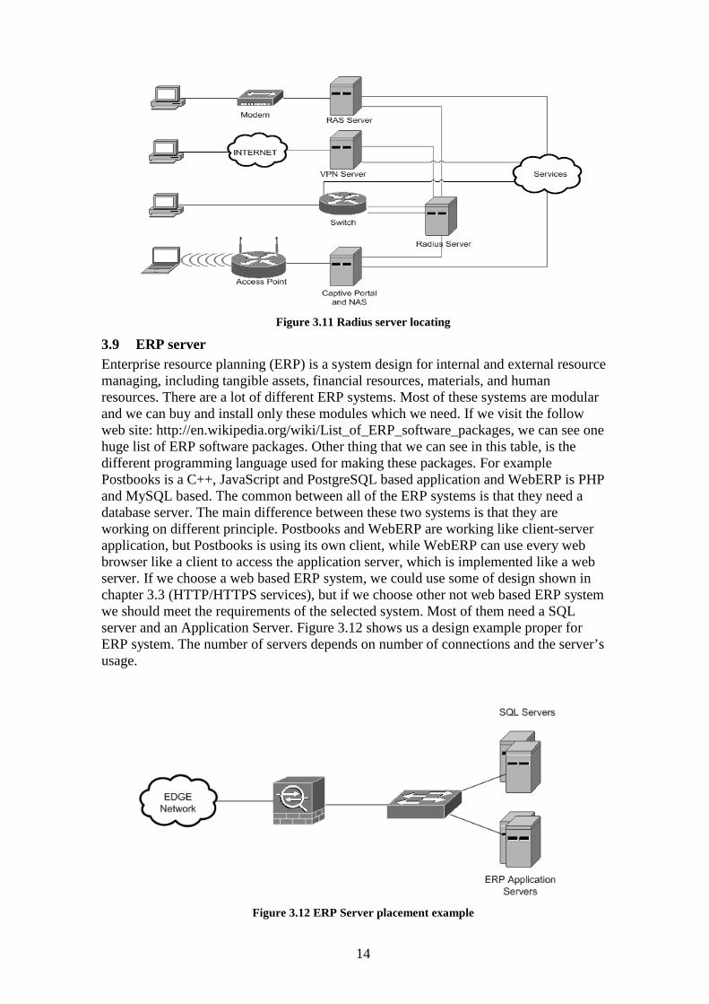
Figure 3.11 Radius server locating
3.9 ERP server Enterprise resource planning (ERP) is a system design for internal and external resource managing, including tangible assets, financial resources, materials, and human resources. There are a lot of different ERP systems. Most of these systems are modular and we can buy and install only these modules which we need. If we visit the follow web site: http://en.wikipedia.org/wiki/List_of_ERP_software_packages, we can see one huge list of ERP software packages. Other thing that we can see in this table, is the different programming language used for making these packages. For example Postbooks is a C++, JavaScript and PostgreSQL based application and WebERP is PHP and MySQL based. The common between all of the ERP systems is that they need a database server. The main difference between these two systems is that they are working on different principle. Postbooks and WebERP are working like client-server application, but Postbooks is using its own client, while WebERP can use every web browser like a client to access the application server, which is implemented like a web server. If we choose a web based ERP system, we could use some of design shown in chapter 3.3 (HTTP/HTTPS services), but if we choose other not web based ERP system we should meet the requirements of the selected system. Most of them need a SQL server and an Application Server. Figure 3.12 shows us a design example proper for ERP system. The number of servers depends on number of connections and the server’s usage.
Figure 3.12 ERP Server placement example

15
4 Security Technologies
In this chapter we will look at the different types of security technologies separated in categories. The main reason of this examination is to find the proper technologies, which we can use in our design and to help us in improvement of the security of our proposed secured network design.
4.1 Identity Technologies These technologies we will use for indentifying the user who is using or working in our network. They are also part from AAA (authentication, authorization, and accounting). The main technologies here are: [6]
4.1.1 Reusable passwords The Table 4.1’s first column shows the main information about this technology. Windows and UNIX usernames and passwords are typical example of this technology. As we see this technologies is easy for implementation and it does not change the performance, and it is quite hard for bypassing from the attackers. Another important characteristic is that the technology is protecting computers and other network equipment from direct access. [6]
4.1.2 RADIUS and TACACS+ These technologies are used for providing centralized services for authentication. Information about Remote Authentication Dial In User Service (RADIUS) and Terminal Access Controller Access-Control System Plus (TACACS+) is show in second column of Table 4.1. It is not so easy for implementation and the performance is a little bit slower than a previous technology, but the bypassing from the attackers is harder. This technology also prevent from direct access, like previous.
Choosing between RADIUS and TACACS+ is not so hard, because RADIUS is open standard and it is widely supported, while TACACS+ is CISCO protocol and it is supported only from CISCO devices. TACACS+ is more often used for management authentication and RADIUS for user authentication. RADIUS has two main advantages:
• Uses UDP packets, which are smaller, then TACACS+ TCP packets. • Use encryption only for password, not for entire communication, which allow
bigger performance. AAA servers can be combined with the OTP technology to provide better security.
[6]
4.1.3 OTP The Table 4.1’s third column shows us information about one-time password (OTP) technology. As we said it is good idea to use it with RADIUS. This technology is hard to be implemented and it is hard to be bypassed from the attackers.
Using the OTP guarantee us that users can not choose weak passwords, users need to remember only PIN (Personal Indentify) code and every password sniffing in the network will not have success. The main disadvantages of OTP are:
• Users need to have their token card for authenticate. • OTP needs an additional server to receive the requests replayed from the
authentication server. • Entering the password need more time. • OTP is too expensive for using in large networks. [6]

16
4.1.4 PKI The Table 4.1’s fourth column shows us the Public Key Infrastructure (PKI) technology information. As we see in it is the harder for management and implementation technology, but not so easy for bypassing by the attackers. It is design for distributing digital certificates which identify users. There are two types of PKI systems – open and closed. An example for open PKI system is when our browser use SSL certificate for some web page. It is used for indentifying more organization, while the closed PKI system identifies only one organization or limited group. The keys are signed from certificate authority (CA). [6]
4.1.5 Smart cards The Table 4.1’s fifth column shows us the smart card technology information. As we can see this technology is easy for implementation and management and in the same time is hard to be bypassed from the attackers. The smart cards have the ability to store information about users in their internal memory. This information is read from smart card readers. These readers can be attached to personal computers to identify the user for using VPN or other network system. [6]
4.1.6 Biometrics The Table 4.1’s last column shows us information about biometric technology. This technology use for identifying something you are. It can be combined with other identifying technologies. Biometric identifying includes voice recognition fingerprints, facial recognition, and iris scans. We can use one or more from these identifying methods. If we decide to use such a identification technology we should be sure that the information transmitted between biometric reader and authentication server, because the information can be stolen and used for authenticate. [6]
4.1.7 Identity Technologies Summary As we can see in Table 4.1 OTP technology provides most overall security. For best secured identifying system we must use at least two technologies. For example is good idea to use OTP and RADIUS. All of these technologies provide us an extra level of identifying. If we need completely secured system we can use more three or four from this technologies. The main task here is protecting from direct access. [6]

17
Attack Element
Reusable Passwords
RADIUS and
TACACS +
OTP PKI Smart Cards
Biometrics
Common example
Windows/Unix username/password
Cisco Secure ACS
RSA SecurID
Entrust Authority PKI
Gemplus
Attack elements detected
Identity spoofing Identit
y spoofing
Identity spoofing
Identity spoofing
Identity spoofing
Identity spoofing
Attack elements prevented
Direct access Direct
access Direc
t access Direc
t access Direc
t access Direct
access
Detection 14 14 0 0 0 0 Prevention 39 39 81 81 81 81 Bypass 2 3 5 3 4 3 Ease of
network implementation
5 4 4 2 2 1
User impact 4 4 2 2 2 4 Application
transparency 5 4 3 3 2 1
Maturity 5 5 5 3 2 1 Ease of
management 4 5 2 1 2 3
Performance
5 4 4 4 4 3
Scalability 3 5 4 3 4 3 Affordability 5 4 3 3 2 1 Overall 59 61 63 54 55 52
Table 4.1 Identity technologies summary [6]
4.2 Host and Application Security These technologies we can use for improving security of the end systems. It is important end systems to be secured, because a lot of the security problems are coming from them. [6]
4.2.1 File system integrity checkers The Table 4.2’s first column shows information about file system integrity checkers. This technology can tell us if we have viruses or Rootkits installed on our computer or server. That is why it is important the technology to be applied on critical servers and computers. This file system checkers work with storing hash value of critical files. In this way if the file is modified in any reason after next check the system will show us difference between hash values. This system is not providing automatic recovering only detecting and we should take some actions. The technology is easy for implementation and do not change the performance of the system. More information about tools which are providing this type of check we can see in [27]
4.2.2 Host firewalls The Table 4.2’s second column shows information about host firewalls. These types of firewalls are also known as personal firewalls. We should install host-based firewalls if we want to add one extra security level on personal computers inside and outside the corporation. It is important to install personal firewalls on all computers which corporate’ employees use outside the corporate network. The main problem here is for

18
management of these firewalls, because not all of them have central management and it is hard to configure manually all computers if the number is more one thousand. [6]
4.2.3 Host intrusion detection system The Table 4.2’s third column shows us information about host intrusion detection systems (HIDS). These systems provide us information about what happening on the selected computer. It gives us tools for analyze and audit of any system, with installed such a system. Host IDS like network IDS need to be optimized to work correctly and to show us only information which we really need. [6]
4.2.4 Host antivirus The Table 4.2’s last column shows us information about Host anti-viruses. This is the most deployed technologies for improving host security. We should install such systems in all Microsoft Windows based servers and work stations. Anti-viruses work with virus databases (definitions) and compare information in our systems with them. [6]
4.2.5 Host and Application Security Summary Table 4.2 shows us common table of the host and the application security. Host antivirus has greater overall points, so it is needed on each of the computers in our network. Adding and file system checkers can only improve our security. Host firewalls and HIDS could be installed too, but this will increase management control. [6]
Attack
Element File System
Checkers Host
Firewalls HIDS Host AV
Common example Tripwire Entercept IPFilter McAfee
VirusScan
Attack elements detected
Application manipulation,
Virus/worm/Tr-ojan, Rootkit
Probe/scan, Remote control
software, Transport
redirection, TCP SYN flood and Direct access
Probe/scan Virus/worm/Trojan
horse and Remote control
software Attack elements prevented
Read following
description
Direct access, Remote control
software Prevention 0 76 0 79 Bypass 4 2 4 3 Ease of network implementation
5 2 5 5
User impact 4 2 4 3 Application transparency 5 1 2 4
Maturity 5 2 2 5 Ease of management 3 1 2 4
Performance 5 4 4 4 Scalability 3 2 3 4 Affordability 5 3 3 4
Overall 61 51 61 66 Table 4.2 Host and Application Security Summary [6]

19
4.3 Network Firewalls Network firewalls are using for secure network perimeter. There are different types of firewalls and here we will look at:
4.3.1 Routers with Layer 3/4 stateless ACLs The Table 4.3’s first column shows us the information about this type of firewall. Access control list (ACL) is used to store information about different kind of restrictions. We can block any Transmission Control Protocol (TCP) or User Datagram Protocol (UDP) port and any IP address as well. Bypassing this restriction is difficult task, as it is shown on the table below. [6]
4.3.2 Stateful firewalls This type of firewall has some of the characteristics of the previous one. The main difference is that Stateful firewall can track connections state. The Table 4.3’s second column shows us information about this type of firewall. Most of the Stateful firewalls track the following primary values- Source port, Destination port, Source IP, Destination IP and Sequence numbers. The main value is Sequence number, because the attacker cannot join in established connection if he does not know the correct sequence number. Another benefit from connection tracking is build-in TCP-SYN flood protection. [6]
4.3.3 Network Firewalls Summary Table 4.3 shows us the main differences between the two types of firewalls. Stateful firewall has more overall point because of connection tracking.
Attack
Element Router with ACL Stateful Firewall
Common example Cisco IOS Router Cisco PIX Firewall, Cisco IOS Firewall
Attack elements detected
Network flooding Network flooding
Attack elements prevented
Direct access, Network manipulation, IP spoofing and IP redirect
Direct access, Network manipulation, IP spoofing and TCP SYN flood
Detection 19.67 19.67 Prevention 123 125 Bypass 2 4 Ease of network implementation
2 3
User impact 3 4 Application transparency
2 3
Maturity 5 5
Ease of management
3 4
Performance 3 4 Scalability 3 4 Affordability 5 4
Overall 80 89 Table 4.3 Network Firewalls Summary [6]

20
4.4 Content Filtering Content filtering technologies, which we will look at them in this chapter, could be combined with the firewalls to achieve one better level of network security. We will see the main function of proxy-, mail- and web-filtering. [6]
4.4.1 Proxy filtering Proxy server and firewalls are quite similar, because they have common function. They are slower than firewalls, because they must reestablish seasons for each client connection, but if we use our proxy server for caching it can be faster. Proxy server can have problems with some application support. If we need to proxy some application through a proxy server, we should give enough information to the server for the protocol using by the application to allow that traffic to pass. The Table 4.4’s first column shows us information about proxy servers and proxy filtering. It is with worst overall result, but this not means that we can not use it in our network. [6]
4.4.2 Web filtering There are two types of web filtering- Uniform Resource Locator (URL) filtering and mobile code filtering. URL filtering is used if we want to block access to any web site URL address. Mobile code filtering is using when we want to check Hypertext Transfer Protocol (HTTP) traffic and to stop any malicious code hidden in this traffic. The Table 4.4’s second column shows us that the main problem of web filtering is the poor performance. All other information is shown on the same table. [6]
4.4.3 E-Mail filtering This type of filtering has the same basic function like the web filtering. The mail filtering server scans incoming and outgoing e-mails for malicious content including for viruses. The performance of the mail filtering server is not so important, because communication with e-mails is not a real time communication, and if it is slowed is not so big problem for most of corporations. The Table 4.4’s last column shows us information about e-mail filtering technology. [6]
4.4.4 Content-Filtering Summary Table 4.4 shows us common table with the three filtering security increasing methods, which we discussed in this chapter.
Attack Element Proxy Server Web Filtering E-Mail Filtering Common
example SOCKS Proxy Websense MIMEsweeper
Attack elements prevented
Direct access Direct access,
Viruses Viruses, Remote
control software Bypass 3 3 4 Ease of
networking implementation
4 4 5
User impact 2 1 5 Application
transparency 1 4 4
Maturity 4 3 4 Ease of
management 3 4 4
Performance 2 1 4 Scalability 3 1 4 Affordability 4 3 3 Overall 43 53 69
Table 4.4 Content-Filtering Summary [6]

21
4.5 Network Intrusion Detection Systems NIDS (Network Intrusion Detection System) can add an extra security level to our network. There are two different types of NIDS- signature-based NIDS and anomaly based. Here we will look at each of them and we will show the main differences between them. [6]
4.5.1 Signature-based NIDS The NIDS work is like a sniffer work. These systems are placed in our networks and watch the traffic and compare it with a signature and if find matches it alarm us. As we see in the Table 4.5’s first column in “Attack elements detection” NIDS have more methods of detection, then any other method of security. [6]
4.5.2 Anomaly-Based NIDS Anomaly-based NIDS have ability to know (or to be configured) normal parameters for the network, where they are places. If there is any change in the network, which is not normal for it, the anomaly-based NIDS will inform us. The Table 4.5’s second column shows us the information about this type of devices. We can see that the overall score is much smaller then the previous one. [6]
4.5.3 NIDS Summary Table 4.5 shows us the summary information about the two typed NIDS. We can see that Signature-based NIDS is much more effective method for network security improving, because it can help us to protect our network from more different attack types. [6]
Attack Element Signature-Based NIDS Anomaly-Based NIDS Common example
Cisco IDS Arbor Networks Peakflow DoS
Attack elements detected
Probe/scan, Network manipulation, Remote control software, Application manipulation, IP spoofing, Network flooding, TCP SYN flood, ARP redirection and Virus/worm/Trojan
Network flooding, TCP SYN flood and Virus/worm/Trojan
Detection 123 43.67 Prevention 0 0 Bypass 3 4 Ease of network implementation
3 4
User impact 4 5 Application transparency
2 5
Maturity 2 1 Ease of management
1 3
Performance 3 4 Scalability 3 4 Affordability 2 2
Overall 68 51 Table 4.5 NIDS Summary [6]

22
4.6 Cryptography The cryptography is using to protect communication between two parties. The main benefits from this type of technologies are- the send messages cannot be read from anyone else inside the party, the participants can identify each other inside the party and the send message cannot be modified while it is transmitting without knowing of the party. Here we will look at four different methods for cryptography in different layers. [6]
4.6.1 Layer 2 cryptography Layer 2 cryptography performs cryptographic methods in Layer 2 of OSI model. The most famous L2 cryptography is Wired Equivalent Privacy (WEP) using in Institute of Electrical and Electronics Engineers (IEEE) 802.11b wireless standard. L2 cryptography is using for WAN links security between financial institutions. The Table 4.6’s first column shows us information about this type of cryptography.
4.6.2 Network cryptography IP security (IPSec) is the standard for network cryptography. It is defined in Request for Comments (RFCs) 2401 by Internet Engineering Task Force (IETF). It is design to be flexible method for providing L3 cryptography. The main benefit of IPSec is that it provides encryption of many protocols with a single security negotiation. The Table 4.6’s second column shows us information about network cryptography, and we can see that overall value is bigger than L2 cryptography. [6]
4.6.3 L5 to L7 cryptography This cryptography is a good alternative of IPSec for some applications and in specific situations. For example for encrypting web traffic is impossible to use IPSec, and it is using Secure Sockets Layer (SSL). Secure Shell (SSH) and SSL are using mainly for management communications and for application specific needs. The Table 4.6’s third column shows us information about this type of cryptography. [6]
4.6.4 File system cryptography Although it is not connected directly with improvement of network security it can help us indirectly. This cryptography technology encrypts entire file system in our computers. This is important if we have mobile users connecting to our network. As we see in the Table 4.6’s last column this cryptography can protect us from direct access and Rootkits. [6]
4.6.5 Cryptography Summary Table 4.6 shows us common information about different cryptography methods. It is wrong to compare them, because they are not working in the same network layer and actually we can use all of them, but the network performance will be slower.
As we can see Network crypto is with more overall summary then others, but it can not be use in every situation and it is good to be combined with others methods where is needed. [6]

23
Attack
Element L2 Crypto Network Crypto L5L7 Crypto File System Crypto
Attack elements detected
WEP IPsec SSL Microsoft's Encrypting File System (EFS)
Attack elements prevented
Identity spoofing, Man-in-the-middle, MAC spoofing, Sniffer and Direct access
Identity spoofing, Man-in-the-middle, Direct access, Sniffer and IP spoofing
Identity spoofing, Direct access, Sniffer and Man-in-the-middle
Identity spoofing, Direct access, Rootkit and Remote control software
Prevention 176 178 148 154 Bypass 3 5 5 4 Ease of network implementation
2 2 5 5
User impact 5 5 3 3 Application transparency
3 3 2 4
Maturity 3 3 4 3 Ease of management
2 3 4 4
Performance 3 3 3 4 Scalability 3 3 3 4 Affordability 3 3 4 4
Overall 91 96 88 91 Table 4.6 Cryptography Summary [6]

24
5 Methods and decisions for corporate network security
In this chapter we will look at different methods and decisions for improving network security in our proposed design. We can not look at all different types of network security improvement decisions and methods, because they are too much and we should keep some normal volume of this project. We will look at only some basic and popular decisions in network security. They are DMZs usage, basic hardering strategies for main devices in the corporate network, rogue device detection.
5.1 Demilitarized zones A demilitarized zone is a zone placed between internal and external network. What will we put inside this zone depends on corporate needs. We can place from one computer or server to large server farm. Using DMZs we can protect corporate servers from direct access from outside network, and in this way to protect important corporate data.
The design of DMZ can be relative simple and very complex. This depends from corporate requirements and the level of protection we want to reach. DMZ provides a multiple layers of protection to servers and machines, which are inside the zone.
We will see some situation of usage DMZs, and will see in which situation what kind of design is better.
5.1.1 A Basic Network with a Single Firewall Figure 5.1 shows us a simple network design with one firewall and one zone. In this situation we will not provide external services. This design can be used if we want to separate part from big corporate network and made a small protected corporate section network. This design is perfect to be used with all main section of a corporate network, and to keep information protected from outside network or other corporate sections. Advantages of this design are: inexpensive, easy for configuration and low maintenance. Disadvantages are: lower security and no expansion variants.
Figure 5.1 A Basic Network with a Single Firewall [11]

25
Figure 5.2 shows the traffic flow of the first design model. The outbound traffic is unrestricted, but the basic configuration will not allow incoming connections which are not started from the internal network.[11]
Figure 5.2 Traffic flow of a Basic Network with a Single Firewall [11]
5.1.2 Basic Network, Single Firewall and Bastion Host Figure 5.3 shows a design of a part or whole network, which can provide implementation of services, which can be accessed inside and outside the protected network. We must have complete security on Bastion Host and only the most important services must be enabled. This design is not proper to use if we need to provide a Virtual Private Connections (VPNs), File Transfer Protocol (FTP) services or other services, which required a regularly content updates. Advantages of this design are: simple design and low cost. Disadvantages are: Bastion Host is vulnerable and not scalable.
Note: Bastion Host is a machine usually a server located in the DMZ with strong
host-level protection and minimal services.

26
Figure 5.3 Basic Network, Single Firewall and Bastion Host [11]
Figure 5.4 shows traffic flow of our second design example. The firewall has no
protection of the Bastion Host. All rules of traffic are configured manually on the machine. Incoming traffic from outside network is blocked from firewall to protect internal network. Outgoing traffic from internal network is allowed. [11]
Figure 5.4 Traffic flow of Basic Network, Single Firewall and Bastion Host [11]
5.1.3 Traffic flow of Basic Network, Single Firewall and Bastion Host Figure 5.5 shows us a design where firewall block all traffic from outside network to Bastion Host, expect traffic to port 80 (for web services) or other ports which are needed to be accessed from outside unsecured network. In this situation the content of the web sites can be updated from inside network (if the firewall is configured properly).

27
Figure 5.5 A Basic Firewall With a DMZ [11]
Figure 5.6 shows us the traffic flow of the third design example. Incoming traffic
reach the Bastion Station if the firewall is configured to allow it. Outgoing traffic from internal network is allowed, even the traffic to DMZ. The traffic from DMZ to internal network is blocked from the firewall. Advantages of this design are: the firewall provides security of internal network and of bastion host, limiting compromise risk and providing some flexibility. Disadvantages are: very complexity and requires split DNS. [11]
Figure 5.6 Traffic flow of Basic Firewall with a DMZ [11]
5.1.4 A Multitiered Firewall With a DMZ In Figure 5.7 is shown basic multitiered DMZ design. In this situation the firewall can use virtual lans (VLANs) with supporting IEEE 802.1q standard. With using this standard in no longer necessary to use two or more firewalls or firewall with more than one physical interfaces. The important requirement here is firewall to be connected to trunked port on the VLAN switch, and in this way the firewall will use different security policies on virtual ports, while reading VLAN tags. If we want to ignore VLAN hopping risk is better to use different physical interfaces for connecting each of DMZs.

28
Depend on configuration of the firewall each Bastion Host can be reached from outside, inside or even from other Bastion Host located in second DMZ.
Figure 5.7 A Multitiered Firewall With a DMZ [11]
Figure 5.8 shows more complex traffic flow. Here we have a real protected DMZ –
DMZ2. Traffic flow of internal network and DMZ2 is determined from firewall. All users in internal network have access to external network and to DMZs, but the nodes from DMZs can not access the users into the internal network. Advantages of this design are: protect bastion host, allow multiply services, limits compromised hosts. Disadvantages are: require more hardware and software for this design, more complexity, require much more configuration work and monitoring.
Figure 5.8 Traffic flow a Multitiered Firewall With a DMZ [11]

29
5.1.5 DMZ design As a part of security design DMZ design in always in progress. The design is very important for overall corporate network security. The proper design can help us to isolate each kind of traffic and connections. It can also protect corporate data from internal attacks. We can implement a multilayered approach, which can help us with securing corporate resources without single points of failure in our plan. This minimizes the problems and loss of protection that can occur because of a lot of reasons. [1]
5.1.6 DMZ protocols The protocols, which can be provided in a DMZ depends on corporate needs. Often some of protocols made our security in this DMZ weak. We should know what kind of security problems we can have if we placed the selected services and protocols. Here is a list of the weakest protocols and the problems which we can meet:
• File Transfer Protocol (FTP) – the problems with this protocol are that it now allows encryption and the authorization information is send in clear text.
• Telnet – the authorization information is send in clear text and can be used for taking control of systems which use this protocol.
• Hypertext Transfer Protocol (HTTP) – a lot of security problems in different web server platforms, bad configured web server can be easy compromised and easy to take access from attacker.
• Lightweight Directory Access Protocol (LDAP) – some platforms are subject to different buffer overflow and DOS attacks
• Simple Network Management Protocol (SNMP) – Buffer overflow and DOS attacks are very possible if we leave the community names and the other information by default.
• Secure Shell (SSH) – this protocol is often under DOS attacks, if the attacker is logged with root privileges he can easy start any kind of code.
• Domain Name Service (DNS) - a lot of security problems in different DNS server platforms. If attacker gets access on this type of server he can redirect all pages where he wants.
5.1.7 DMZs network resources protection methods In this section we will show the methods of increasing network security protection.
• Using Firewall Firewalls were, are and will be the important part of the most DMZ implementations and designs. How many firewalls and how we will use them depends on the corporate requirements. Different design we already show previous in this point of the project. Part of the DMZ design is testing of different types of software or hardware based firewalls.
• Using Screened Subnets If we need more advanced DMZ design and the requirements are more complex we can use screened subnets for service protection. To provide this type of security implementation is needed more hardware, which means that it is more expensive than other methods. The simplest design is when we use firewall with more than one interface and capabilities to provide traffic filtering on each of its ports. With this method we can easy proved secured services as WEB, E-MAIL, VPN or FTP.
• Securing Public Access to a Screened Subnet With this method we can reach secure public access to screened subnet, with using a router for basic security and a firewall for deep security. [11]

30
Figure 5.9 A Basic Screened Subnet [11]
As we can see in Figure 5.9 the protection begins from router. We can easy
configure Access Lists (ACLs) to block unwanted IP addresses. The second level of security is provided from firewall. We can configure it to filter or block any kind of traffic. [11]
5.1.8 What kind of servers we can locate in DMZs In this section we will discuss what kind of servers we could place in our DMZ and what function they can play.
• Application Servers Applications servers in a DMZ must be very carefully configured. We must be sure that all security patches of selected operation system (OS) are installed all the time. All unused services must be disabled or removed if it is possible. All services which we provide must be carefully configured to work only with proper corporation data. Critical or confidential information must not be located in DMZ. If we need SQL server in this zone, we must be sure that it not contains such a data. It is not acceptable to put servers which contain information for our internal network infrastructure or other user information, such a DNS servers and Mail servers. If we need such a services, it is better to use an application proxy server inside DMZ to forward these types of requests. The traffic from internal network to the services in DMZ must be passing through firewall. [11]
• Domain Controller Domain controller servers or other active directory authorization server must never be places in DMZ. If the attacker take control or some access on bastion host and after that can get access on DC information and take control on entire internal network. Domain controller servers can be used in DMZ only in cases, when we need to connect some servers each other, but in this case we must be very careful with the configuration of this servers. [11]
• RADIUS-Based Authentication Servers Remote Authentication Dial-In User Service (RADIUS) servers must be fully protected and patched with latest updates. In his definition this type of servers are for providing services as full access to the authentication information used by Directory Services

31
systems, and if attacker can manipulate with information from this server, he can take different levels of access. The preferred option to use the RADIUS server located in the internal network is with proxied requests coming from a Routing and Remote Access Services (RRAS) server which must be allowed through the firewall to the RADIUS server only from the specified RRAS servers. It will be good to use IPsec, if it is possible, to protect our traffic. [11]
• VPN servers VPN are more often used in last few years. Many corporation use VPN to connect theirs main office to all its branch offices all over the world. All incoming connections from the branch offices must be accepted from VPN server, which can be more that one. If we want to locate this or this VPN server in DMZ, is better to make new zone for them, which must be separated from other network resources and from other DMZs. This new DMZ will be used as door to internal corporate network, and because of this it must be carefully design and protected. It is good to use IPSec and its authentication and encryption possibilities as well as IDS and IPS. [11]
• Web and FTP servers If we need Web and FTP server in our corporate network, this will make a change in DMZ design. In many cases the company’s clients or partners need to have access of these services. When we make the security design we must be sure that all partners and clients privileges can not make any security issues. If we can separate Web and FTP servers, which will be used from outside, from these which are need for internal corporation use, will be one of the best solutions. [11]
• E-comers servers We can put servers for e-comers services in our DMZ, but we must use additional mechanisms for defense the client’s information, such as credit card numbers, names and other personal information. These mechanisms can be using SSL (Secure Sockets Level) or firewall restrictions to allow only client’s range of addresses, if we know it. It is good to use multitiered DMZ structures, because we can restrict the communications between the applications, like core web servers, database servers, authorization servers and other part of the e-comers system.
• Mail servers E-mail services are one of the most used services in corporations. SMTP gateways must be located in segregated DMZ subnets, with firewalls configured to allowed requests on ports TCP 25 and UDP/TCP 53. There are two important configurations which we must plan. First is connected with external firewall. It must be configured to block outbound SMTP traffic which not originate at the gateway. Second is that the server must be configured to can send messages only to hosts which are in our internal network or other trusted range of addresses. [11]
5.2 Device Hardering Device hardering is method for securing the different devices in the network. It includes changing default setting and tuning them for increasing theirs and network’s security. This can have many different meanings from disabling the unneeded services in corporate servers to disabling unused ports in entire network equipment. [8]
5.2.1 Hardering strategy components Here we will look at main components of one hardering strategy and we will discuss some main characteristics.
• Security polices- our security polices takes big part from our network security. This polices give us rules and guidelines for using and configuring network resources and devices.

32
• Device location- device location is one of the most important factors in our hardering strategy. Even we make the best configuration of the devices, if they are not in proper secured location, their security in risk.
• Threat profile- this part defines attacks which could be done on each devices. • Functional requirements- two same devices in one location may have two
different hardering strategies. This is possible because they may have different functional requirements.
• Management requirements- like functional requirements, management requirement could be different for same devices.
5.2.2 Network devices Network devices include routers, switches, firewalls, NIDS and NIPS (Network Intrusion Prevention System). Availability of console port is important characteristic for all network devices. The console port gives a privilege access, and even there is a password it is weak and easy can be changed. We should have restricted and controlled access to all devices with console ports.
• Routers- router hardering is important, because attacks to routed network infrastructure are more and more. Here are basic hardering settings:
o Disable Unneeded Services o Password Encryption o Authentication Settings o Enable Secret o Login Banner o Line Access o Setting Up Usernames o Management Access o Etc.
In addition we can make configuration for: o Antispoof filtering o ICMP (Internet Control Message Protocol) filtering o L2 security protections o Routing protocol authentication o Denial of service (DoS) mitigation (against and through the router)
More information about specific router hardering we can find here: http://www.cisco.com/en/US/tech/tk648/tk361/technologies_tech_note09186a00801
20f48.shtml Building Bastion Routers Using Cisco IOS (Internetwork Operating System):
http://www.phrack.com/phrack/55/P55-10 NSA Router Security Configuration Guide: http://www.nsa.gov/snac/cisco/ • Switches- hardering strategy for switches is similar like router’s one. We should
make the same basic hardering settings and additional too if they are supported form used switch.
• Firewalls- with default settings firewalls are more secured then switches and routers. Basic hardering settings include:
o Login Restrictions o Enabling SSH o Logging o Disable Unneeded Services o Password Encryption o Authentication Settings o Enable Secret

33
o Login Banner o Line Access o Setting Up Usernames o Management Access o Etc.
For additional hardering options we should see selected firewall manufacture documents.
• NIDS- these systems do not support any specific services, and their securing is easier then another network devices. The most important things here are to be sure that detection interface is not reachable at L3 and the management interface is connected directly our management network. After first login in NIDS we should make changes of shown parameters:
o IP address o Hostname o Routing o Access control to the sensor management o Communications infrastructure (communication back to the IDS manager) o Password for primary IDS user o Secure Sockets Layer (SSL) and SSH access for management
We can use and router’s basic hardering settings here, if they are available.
5.2.3 Host Operating Systems Host OS (Operation System) hardering is important part of improving security of entire corporative network. With good hardering of OS we can stop all attacks to the network, which are coming from inside the network. Hardering depends on if we have anti-virus software, host firewall and host IDS. Each OS has different hardering configurations. In one network we can use more than one type of OS. For example we can use Microsoft Windows OS and some distribution of UNIX or BSD. Here are some information sources for hardering of the different OS: [7]
o Windows Microsoft -http://www.microsoft.com/technet/treeview/ default.asp?url=/technet/security/tools/tools.asp.
o General UNIX - Practical UNIX and Internet Security, Third Edition, by Garfinkel, Spafford, and Schwartz (O'Reilly, 2003).
o Solaris Sun - http://www.sun.com/software/security/blueprints/. o Linux- http://www.linuxsecurity.com/docs/harden-doc/html/securing-debian-
howto/index.en.html. o BSD UNIX - http://people.freebsd.org/~jkb/howto.html.
5.3 Rogue Device Detection Rogue devices are devices which are placed in our network from intruders to compromise our network. It is easy to be detected in small network with 10 computers, but in large corporate network it is very hard. There are some rules which can help us to protect our network from this kind of device:
• Authenticate valid devices- all devices in the network to have identification system. Using IEEE 802.1x and authentication routing protocols are good practice.
• Map the network- we can use freeware network scanners or commercial ones to make a snapshot of the network. Most of these software could identify the computers OS, which can help us, too.
• Establish strong physical security- if we have strong physical security it would be more difficult placing of rogue devices in our network.

34
• Consider technology- there are several software product, which can detect new devices. For example APTool can detect all wireless access points which are working near and inside our network.

35
6 Network Design Principle and Methodology
In this chapter we will show the main stages of PDIOO methodology model. We will use it to design our proposed model. PDIOO is proper methodology because it could be used for designing all technologies, include and network security.
Figure 6.1 shows the PDIOO process, in which each stage builds on its predecessor.
Figure 6.1 Stages of the PDIOO Process [6]
Optimization can even lead to a redesign of the network, so the cycle would begin
again. Design is just one component of a network life cycle. Planning, design,
implementation, operation, and optimization (PDIOO) are the stages of the network life cycle. Each stage builds on its predecessor to create a sound network that maintains its effectiveness despite changing business needs. You can apply the PDIOO methodology to all technologies. During the PDIOO process, you define key deliverables and associated actions with a direct correlation to the added value and benefit for the client's network. For example, understanding business goals, usage characteristics, and network requirements helps you avoid unnecessary upgrades and network redesigns, thereby reducing the time it takes to introduce new services in the network. [6]
• Planning Phase During the planning stage, you can test the logic of your future design for flaws. Planning helps you avoid replicating a logical mistake in a network design that you might use as a template across a number of locations. The planning stage focuses on technical as well as financial criteria and takes into account all the requirements and constraints that were discussed in the previous section. During this phase, it is important to identify all the stakeholders in order to make this process a success. The stakeholders are people or organizations who have a vested interest in the environment, performance, and outcome of the project. [6]
• Design Phase After completing the planning stage, you have enough information to develop a network design. If a network is already in place, use this phase to review and validate the network design as it is currently implemented. At this stage, you choose products, protocols, and features based on criteria defined in the planning stage. You develop network diagrams to illustrate what changes will occur in the network to achieve the desired results. The more detailed the network diagram and plan, the better you can anticipate the challenges during implementation. [6]
• Implementation Phase The implementation stage provides detailed, customized deliverables to help avoid risks and meet expectations. A sound implementation plan ensures smooth deployment even when issues arise. Communicating the implementation plan to all stakeholders provides you with an opportunity to assess the viability of the plan. It is better to find mistakes on the drawing board than during implementation.
Good processes, such as change control, can effectively handle issues that occur during deployment. Change control provides flexibility because it is impossible to plan for every contingency, especially if the implementation has a long duration. [4]

36
• Operation Phase The operation phase, also known as the operational-support phase, is designed to
protect your network investment and help your staff prevent problems, maximize system utility, and accelerate problem resolution.
• Optimization Phase The last step in the PDIOO process is the optimization of the network. A sound design still requires optimization and tweaking to reach its full potential. The optimization of the network can be as simple as hardening servers against security threats or adding QoS to the network for latency-sensitive traffic.

37
7 Network designing
In this section we will design two parts of one secured corporate network. One of the parts is Edge design and the other one is internal network design. We will put requirements of the most important devices and servers in the networks. The design will be flexible and we will show which the options are and what you can change to satisfy other corporate requirements.
7.1 Principal Scheme Figure 7.1 shows us the proposal principle scheme of our corporative. According to [15], it is better to separate whole network in two main parts- Edge and Internal parts. The Edge network will be connected to the Internet and to the internal network. It is important to use more than one connection to the Internet, because there are a lot of advantages which are not connected only with the network security.
The availability of two or more connections to the Internet is needed if we want to reach high level of the corporate servers’ uptime. Another advantage, which is directly connected with our purpose for improving the network security, is that we can use load-balancing and in this way we can reach some extra kind of different flood attacks protection.
Figure 7.1 Proposed principle design
7.2 Corporate Edge Security Design This part of the network is connected with the Internet and with the internal network. We show our proposal for connections between these networks. The main points discussed here are: Design Requirements, Design Overview and Design Alternatives.
7.2.1 Design Requirements In this part we will show the requirements which we will follow and which are connected with our proposed Edge network:
• Connection to the Internet and other outside networks – this decision is one of the most important in this section. In the next section of this point we will describe what kind of connections we will use and why.
• Servers – here we must decide what kind of servers our corporation needs. We will choose some of the designs for DNS servers, Mail Servers and Web servers discussed in the theory part of the project. We will think about placing of VPN server in this part of the network, but we will not look at the details about it.
• VPN tunnels – this option is included in our design, because we need to provide access to the corporate network of remote or traveling employees. Here again we will include this option of the network, but we will not look at it in details, because it connecting of the remote users and branch offices are subject of other project.
• High availability of the internet connection– this feature is needed, because our network must provide as much as possible uptime for servers and services

38
provided outside the network. This is not an absolute security requirement, but we will include it.
• Network monitoring – we must include tools and techniques for network monitoring, intrusion and attacks attempts. More details about tools for testing and monitoring we will show in the testing chapter of the project. In this chapter we will show places in the network, where we should monitor and test the network for different attacks and issues.
• Security – we must provide a high level of network and server security. This is the main point of the project. In the designing process we will follow with higher priority security requirements discussed in the theory part of this project.
7.2.2 Design Overview On Figure 7.2 is shown our proposed design model of the Edge network of our corporate network.
Figure 7.2 Proposed Edge network design
The good performance and high level of security are the goals in this design.
Server Segments In this section we will make detailed design of Mail, Web, DNS services as main services provided in the edge network and in the Internet. We will show where could be placed VPN servers, AAA servers, Backup servers and other corporate servers but will not look in details and examples about them. More details and examples about these kinds of services we will leave for future work or like assessment for another project.
• Mail Servers- We will use Distributed Two-Tier E-mail Design, which is described in details in the theory part of the project. In this part of the network we need an External SMTP server. Its has two roles- to relay messages from outside to mail antivirus server located in internal part of the network, and to receive scanned messages from internal network and send them to outside the corporate network. This design of mail servers gives us greater scalability. When we are placing these servers in our network, we must be sure that we have made all stages of server Hardering, which we discussed in theory part of the project. We must provide OS and Application Hardering and file system integrity check.

39
• Web Severs- We will use modified Two-Tier Web Design, which is described in
details in the theory part of the project. In this part we need a Web server for providing services outside the network, that is why we need this design. Its main characteristic is that here we will use Application and Database servers installed on one physical server. We will use version with one firewall, but we will place them on different ports with different security settings. The main function of this firewall is to watch the traffic and to block all traffic which is not for these servers. Here again we must set all stages of server Hardering, which we discussed in theory part of the project and to provide OS and Application Hardering and file system integrity check, too.
• DNS servers- We will use Distributed DNS Design, which is described in details
in the theory part of the project. This design requires placing a Master DNS server in this part of the network. We increase security of this service by using layer separation of DNS architectures. When an internal computer makes a request to its DNS server, it forward all queries that it can not resolve to group of servers, which have permission to make queries outside the network. We must provide the same steps for security improving, like previous type of servers.
• VPN servers- this device is connected at first routers in the network. There are
possibilities to add devices for Site-to-Site VPN connections for making secured connections with branch offices or corporative partners, but as we said in the beginning of this section, we will leave it, because it is subject of another project. Here we will show only an example of requirements for providing this kind of service. In our requirements we said we need secured connections between remote users or branch offices, so we need to use IPSec for example to secure the traffic between the end points and our corporate network. It is good to allow only this type of traffic to reach the VPN Access servers. This additional configuration must be done on the WAN Router in Edge design. Here are some techniques and requirements which we must use on these devices to reach the required security level: o We must use techniques for device Hardering which we discussed in theory
part of the project. o We must allow only IPSec VPN connections. o We must activate router’s ACLs, and to configure them to allow only IPSec
traffic to reach to the VPN access devices. o We must use some type of authentication with digital certification. The
different types are shown in theory part of the project. The best choice here is to use PKI model for Site-to-Site connection and OTP model for single VPN connection, because they satisfy our requirements.
WAN Router In our design we use two connections to the Internet. We will not use PSTN and Private WAN connection, but they can be included in the design if we need them. Here are some techniques and requirements which we must use on these devices to reach the required security level:
o We must use techniques for device Hardering which we discussed in theory part of the project.
o We can use any L3 filtering if it is needed, by using ACLs.

40
o We must use unicast RPF to enforce RFC 2827 filtering in incoming and outgoing directions.
o We must use RFC 1918 filtering in incoming and outgoing directions. o We must use filtering of ICMP packets by using best practices. o We must complete all DDoS protection best practices. Although our ISPs
have role to prevent DDoS threats, there are technologies such as CAR, which we can implement in our network.
Stateful Firewalls (FW) FW is the main firewall in our proposed design model. Here are some techniques and requirements which we must use on these devices to reach the required security level:
o We must use techniques for device Hardering which we discussed in theory part of the project.
o We must use RFC 1918 and RFC 2827 filtering in incoming and outgoing directions.
o We can do specific filtering to the devices which are directly connected to the firewalls interfaces.
o We must use filtering of ICMP packets by using best practices. o We must use TCP SYN best practice [28] to protect our network from TCP
SYN flood attacks.
Network Intrusion Detection Systems (IDS) In our design we are using one NIDS. It must watch all traffic between EDGE and Internal network. Here are some techniques and requirements which we must use on these devices to reach the required security level:
o We must use techniques for device Hardering which we discussed in theory part of the project.
o The devices must be tuned to detect attacks only in area of the network where they are placed. In our situation we can choose which traffic to watch or we can to watch all traffic between the two networks.
Ethernet Switches (SW1 and SW2) There are two Ethernet switches in our proposed model, but they can be more if we need some extra functions or if we need some kind of extension. SW1 is directly connected to WAN router. SW2 is the last switch between Edge and internal networks. There is an IDS connected to it, which mean that we must configure ports for it. Here are some techniques and requirements which we must use on these devices to reach the required security level:
o We must use techniques for device Hardering which we discussed in theory part of the project.
o We must provide best practice for L2 protocol [1] o We must enable and configure port security on all switches in the network. o We must use VLANs hopes best practice on switches where we use VLANs.
7.2.3 Design Evaluation Table 7.1 shows us how our proposed design of the Edge part of the network can resist of top 10 attacks(rated according to [1]) As we see the process of hardening of the devices is one of the most important way for security improving. IDSs are the devices which can help us to avoid and stop most of the attacks in the table. The Stateful firewalls can defend us from only two types of attacks in the table- TCP SYN flood and

41
Direct access attacks, but there are many others attacks and threats which are not in the table and could be stopped only with this type of firewall.
Type of Attack Method of Detection Method of Preventing
Buffer overflow attack File system check,
Host IDS, Network IDS OS hardening, Application hardening
Virus/worm/Trojan horse File system check,
Network IDS, anomaly NIDS, DDoS best practice
Host Anti-Virus and E-mail filtering
Direct access Host IDS
Reusable passwords, PKI, Stateful Firewall, router with ACL, all kind of hardening, session app crypto, Private
VLANs, routing protocol authentications
Probe/scan
Host IDS, Network IDS, application/OS hardening, Stateful
Firewall
Network device hardening, ICMP best practice
Application flooding attacks Host IDS, Network
IDS, anomaly Network IDS
Application and OS hardening
Rootkit File system check Application and OS hardening
Remote control software Host IDS, Network
IDS Host Anti-virus, Application and OS
hardening Identity spoofing Reusable passwords PKI and session app crypto
Web application File system check,
Host IDS, Network IDS Application and OS hardening
TCP SYN flood Host IDS, Network
IDS, Stateful Firewall, TCP SYN Best
practices Table 7.1 Proposed Edge Design Attack Resistance
7.3 Internal Corporate Network Security Design In this proposed design for internal network we will use one main firewall which will control and monitor the traffic in the network. When we choose this type of firewall in next chapter, we should be sure that it is suitable for this role and this load.
7.3.1 Design Requirements Here, like in the previous section we will set requirements which we will follow in our design and they are:
• To provide connectivity for several types of servers located in corporate data center.
• To provide different clients subnets with allowed access to these servers. • Server types we need- DNS server, Mail Server, Web server, LDAP server and
other corporative servers.
7.3.2 Design Overview Figure 7.3 shows our proposed design model for internal corporate network. This design can satisfy the requirements of our assignment. We can provide several data centers, but we do not need it with these requirements.
The network organization in our proposed model is made with one central firewall (Main FW). When we choose a concrete model for this firewall we must know that it is in the middle of the network and it would be under huge load. This main firewall is directly connected to all main parts of the internal network. FW1, FW2 and FW3 are firewalls which should protect the different server farms (Mail servers, DNS servers and

42
Web servers). They are also directly connected to the main firewall through the switch SW3. This is needed to make the used firewall ports less and to separate the security settings and requirements between all firewalls in our design.
The IDS1 and IDS2 function is to check, analyze and monitor traffic going and coming to and from LDAP and Corporative server farms [29].
The role of the switch named Access SW is to connect all other switches on the access level of our design network. We could use some extra features on this switch like ACLs and QoS, if we need to decrease the main firewall load.
Figure 7.3 Proposed internal network design
Ethernet Switches (SW1, SW2 and SW3) All devices in our design have specific role for providing high level of network security. Here are some techniques and requirements which we must use on these devices to reach the required security level:
o We must use techniques for device Hardering which we discussed in theory part of the project.
o We must provide best practice for L2 and L3 protocol [1]. o We must enable and configure port security on all switches in the network. o We must use VLANs hopes best practice on switches where we use VLANs. o We must limit the numbers of MAC addresses per port on the switch with
using port security option. o We must provide ARP inspection on these switches. This will increase
security level. o We must use VLAN ACLs here to protect our network from rogue DHCP
servers.

43
Ethernet Switches (Access SW) Here are some techniques and requirements which we must use on these devices to reach the required security level:
o We must use unicast RPF to enforce RFC 2827 filtering in incoming and outgoing directions.
o We can use these switches to block traffic flows at Layer3/Layer4 if it is needed and if security polices require this.
o We must use role-based subnetting to segment the user roles. We will use VLANs here, because it is easy for implementing and managing and we will avoid using a lot of L2 switches if we choose physical separating of the networks. We can use InterVLANs routing with switches and routers if we need it for future extending.
Network Intrusion Detection Systems The two main IDS are IDS1 and IDS2. They are connected to the main server farms switches. In this way we can monitor any traffic to and from servers located in selected data centre. Here is good to use tuning and filtering of the information recorded from these IDS, because the amount of transmitted data will be huge. Here are some techniques and requirements which we must use on these devices to reach the required security level:
o We must use techniques for device Hardering which we discussed in theory part of the project.
o We must tune the devices to detect attacks which are typical for these types of servers and this type of infrastructure.
Stateful Firewalls (Main FW) In our design we are using one main firewall, which must actually provide the protection of our entire internal network. Here are some techniques and requirements which we must use on these devices to reach the required security level:
o We must use techniques for device Hardering which we discussed in theory part of the project.
o We must implement Stateful access control. o We must use unicast RPF to enforce RFC 2827 filtering in incoming and
outgoing directions. o We must use TCP SYN best practice [28] to protect our network from TCP
SYN flood attacks.
Stateful Firewalls (FW1, FW2 and FW3) Here we are using three firewalls, which must provide some extra protection of the servers located in data centre. Here are some techniques and requirements which we must use on these devices to reach the required security level:
o We must use techniques for device Hardering which we discussed in theory part of the project.
o We must implement Stateful access control. The firewalls are connected each other and state information must transact between these firewalls and if one fails, others can check if the sessions stay connected.
o We must use unicast RPF to enforce RFC 2827 filtering in incoming and outgoing directions.
o We must use TCP SYN best practice [28] to protect our network from TCP SYN flood attacks. This must be done on these two firewalls.

44
These extra firewalls will reduce the main firewall load, because it will not be busy to filter, inspect and follow the traffic from and for these servers.
Internal Servers As is written in our assignment we need Mail, Web, DNS and LDAP servers. We must think also about other typical corporate servers like Enterprise Resource Planning (ERP), business intelligence (BI), Human resource management (HRM), Document management system (DMS) and etc. These servers must be hardened and protected like these in Edge part of the network.
• Mail Servers- We will use the Distributed Two-Tier E-mail Design, which is
described in details in the theory part of the project. In this part of the network we need an Internal Mail server and Antivirus Mail Server. The functions of the Internal Mail server(s) is to route and scan, to send all e-mails to Antivirus Mail Server and allow internal users to get their e-mail. The function of Antivirus Mail Server is to scan messages from and to outside network. This design of mail servers gives us greater scalability. When we are placing these servers in our network, we must be sure that we have made all stages of server Hardering, which we discussed in theory part of the project. We must provide OS and Application Hardering and file system integrity check.
• Web Servers- We will use the Two-Tier Web Design here, which is described in
details in the theory part of the project. In this part we need a Web server for providing services only inside the network that is why we need not the strongest design. Its main characteristic is that here we will not separate Application and Database servers and we will place them on a single physical machine. The main function of the firewall (FW3) is to watch the traffic and to block all traffic which is not for these servers. When we are placing these servers in our network, we must be sure that we have made all stages of server Hardering, which we discussed in theory part of the project. It is highly recommended to provide OS and Application Hardering and file system integrity check, too.
• DNS servers- We will use the Distributed DNS Design, which is described in
details in the theory part of the project. This design requires placing two Internal DNS server and one or more DNS Forwarder Servers in this part of the network. We increase security of this service by using layer separation of DNS architectures. When an internal computer makes a request to its DNS server, it forward all queries that it can not resolve to group of servers, which have permission to make queries outside the network. The function of FW2 is to provide extra security and monitoring of these servers. When we are placing these servers in our network, we must be sure that we have made all stages of server Hardering, which we discussed in theory part of the project. We must provide OS and Application Hardering and file system integrity check, again, like with previous types of servers.
• LDAP servers- the number of the physical servers which we need to provide this
kind of services in our network depend on the number of users which will use this services. We are designing a network for mid-size corporation (500-1000 user computers), so we need physical server(s) which is with carefully chosen hardware configurations. We will show example hardware configuration in next chapter of the project. In our situation we will make configurations for two main

45
directory servers. The first one will be primary domain controller server, and the second one will be secondary (backup) server. This group of servers is connected to the main firewall through the management switch SW1. We must configure this firewall to allow all traffic connected with the LDAP service and to block all other traffic of this port. IDS1 is connected to the SW1, so we must configure one of its ports to mirror all traffic, so IDS1 can watch and analyze it. All other security options for LDAP servers are written in theory part of the project.
• Other corporate servers- this part we will not discuss in details, only we will set
the place for these servers. We look at the different types of ERP systems, which actually include all corporate sub systems, like HRM and DMS. We will make the design to satisfy the model shown in Figure 3.12, so we need an application server and a database server. The numbers of the servers we will leave for future work in this project. Another important server group for every corporate network is the Backup and disaster recovery servers. These groups of servers are connected to the main firewall through the management switch SW2. We must configure this firewall to allow all traffic connected with these services and to block all other traffic of these ports. IDS2 is connected to one of the SW2 ports, so we must configure it to mirror all traffic, so IDS2 can watch and analyze it.
User Computers In most cases if we have try for attacking of internal servers, usually attacker has access to some of user computers. There are a lot of ways the attacker to get access on one or more of these computers (worms, virus or other application). Here are some techniques and requirements which we must use on these devices to reach the required security level:
• Users must use authentication on their systems with usernames and passwords. • We must use OS and Application hardening. We will use Active directory
structures to control the OS and user profiles. • We must install Host Antivirus on every computer in internal network. • We must install and configure Host Firewall, which can give us additional
system protection. We must use File System crypto, especially on computers which are using from
travelling employees.
7.3.3 Design Evaluation Table 7.2 shows us the most popular attacks for internal networks and methods of detection and prevention in our design.

46
Type of Attack Method of Detection Method of Preventing
Identity spoofing Reusable
passwords, RADIUS/TACACS+
Session app crypto, file system crypto, PKI
Virus, worm, trojan horse File system check, Network IDS
Host Anti-Virus and E-mail filtering
Rogue devices Rogue device detection Best practices
[30]
Sniffer
Session app crypto, L2 control Best practices, port security, ARP Best
practices, DHCP Best practices, private VLANs
Man-in-the-middle attacks Session app crypto, rogue device
detection Best practices, ARP BPs, DHCP Best practices
War dialing/driving Rogue device detection Best practices
Direct access Host IDS, Network
IDS
Reusable passwords, RADIUS/TACACS+, PKI, host firewalls, session app crypto, Network, Application and OS hardening, PVLANs, file system
crypto, router with ACL, role-based subnetting, stateful firewall
ARP redirection and spoofing Network IDS ARP BPs, private VLANs
Remote control access Host IDS, Network
IDS
Host Anti-Virus, host firewalls, Application and OS hardening, file
system crypto, e-mail filtering
Buffer overflow File system check,
host IDS, Network IDS Application and OS hardening
Table 7.2 Design Evaluation Here again more often used method of protection is the all types of hardening.

47
8 Network equipment
In this chapter we will choose concrete network equipment, which cover all the requirements shown in the project.
Most of the manufacturers have their own products for building corporate networks. Some of the manufacturers use their own protocols (for example Cisco – EIGRP routing protocol), and if we use some of them it is good to use network equipment of only one manufacturer. Despite of that we will not use any specific network protocol we will use only one manufacture for all network devices in our proposed network, because it will be easy for implementing in our virtual environment.
Between the simulating tools which we looked in the theory part of the project the most proper is GNS3 and we will see why in the Testing chapter. The important here is that this simulator works with real image files of almost all Cisco network equipment and we can connect servers simulated with tools for OS simulating to make complete virtual model of entire corporate network. After this restriction in GNS3, we will make decisions about which model of network hardware is the best for our network. Of course in one real situation we can change the chosen equipment with another but with the same characteristics and features.
8.1 Firewalls In this section we will show concrete network firewalls models from one of the biggest network equipment manufacturers- Cisco Systems. The requirements for each of them are different, that is why we will choose each of them carefully.
Cisco firewalls are named Cisco ASA. There are seven different models with different characteristics and we must choose between them. Table 8.1 and Table 8.2 show us the most important characteristics which are directly connected with our choice.
8.1.1 Edge Network In this part of the proposed corporate network we are using only one network firewall. Here are the requirements for choosing model for it:
• To be designed for this type of location – Internet Edge or Campus networks. • Minimum 6 configurable ports with different traffic rules and restrictions. • Stateful firewalling • Options for secured VPN connections (if we choose firewall with this options
we can remove the separated VPN server from our final network design, because it will be not necessary).
• 100 VPN connections in the same time (this is 10% from users in entire corporate network and they could work remotely with the corporate network resources)
As we can see in the Table 8.1and Table 8.2 all models after ASA5510 satisfy our requirements, but ASA5510 does not support high-availability options. As we can see in our proposed design in Figure 7.2 to this firewall are connected all public servers so it is good to choose the bigger model between ASA5520 and ASA5540, because of the bigger number of firewall connections and connections per second. In other case the ASA5540 has two times more memory and this model allow us future extending of the network. Our choice for main firewall in the Edge network is Cisco ASA5540.
8.1.2 Internal Network In this part of the network we are planning to place four firewalls. One of them is the main firewall of the internal network and its characteristics should be similar like this

48
placed in the edge part of the network. Here are our requirements for choosing the right model for main firewall in the internal network (Main FW):
• To be designed for this type of location- internal network and campus • Minimum 5 configurable ports with different traffic rules and restrictions. • Stateful firewalling • Options for secured VPN connections (for now we will not use any VPN
connections to this firewall, but we will include the option for future extensions).
As we can see in the Table 8.1and Table 8.2 all models after ASA5510 satisfy our requirements, but ASA5510 does not support high-availability options. The servers placed in this part of the network are designed only for internal usage, so we will not have any connection from the outside the network except the remote users which we set to 10% of all user, which mean maximum 100 external VPN users, but they will make their connections to the internal network through the firewall placed in the Edge network. Here the main characteristic for choosing will be the Maximum firewall throughput, which is almost two times more in ASA 5550 compare to ASA 5540. We will choose Cisco ASA 5550, because it has 1Gbps Maximum firewall throughput, which will be enough for our maximum number of computers.
We have another three firewalls placed in the internal network with almost the same functions, but with different settings and software configurations. FW1, FW2 and FW3 are placing there to control the traffic to and from different server’s types. Here the common requirements are:
• To be designed for this type of location- internal network, part of network • Minimum 3 configurable ports with different traffic rules and restrictions. • Stateful firewalling • 300Mbps Maximum firewall throughput is enough for all server types, in case
that we need more, we can always change it with greater model. With these characteristics we can choose Cisco ASA 5510 for proper model for
placing in the network on the place of FW1, FW2 and FW3.

49
Cisco ASA 5500
Series Model/License
5505 Base 5510 Base 5520 5540
Network location Small Business, Branch Office
Internet Edge Internet Edge Internet Edge
Performance Summary Maximum firewall
throughput 150 Mbps 300 Mbps 450 Mbps 650 Mbps
Maximum firewall connections
10,000 50,000 280,000 400,000
Maximum firewall connections/second
4000 9000 12,000 25,000
Maximum 3DES/AES VPN
throughput
100 Mbps 170 Mbps 225 Mbps 325 Mbps
Maximum site-to-site and remote
access VPN sessions
10 250 750 5000
Maximum SSL VPN user sessions
25 250 750 2500
Technical Summary Memory 512 MB 1 GB 1 GB 2 GB
Minimum system flash
64 MB 64 MB 64 MB 64 MB
Integrated ports 8 port 10/100 switch with 2 Power over
Ethernet (PoE) ports
5-10/100 +4-
10/100/1000 4 SFP (with 4GE
SSM)
4-10/100/1000,
1-10/100 +4-
10/100/1000, 4 SFP (with 4GE SSM)
4-10/100/1000, 1-10/100
+4-10/100/1000, 4 SFP (with 4GE
SSM)
Maximum virtual interfaces (VLANs)
3 50 150 200
Features Application-layer firewall services
Yes Yes Yes Yes
Layer 2 transparent firewalling
Yes Yes Yes Yes
Security contexts (included/maximum)
0/0 0/0 2/20 2/50
GTP/GPRS inspection Not available Not available
Yes Yes
High-availability support
Not supported Not supported A/A and A/S A/A and A/S
SSL and IPsec VPN services
Yes Yes Yes Yes
VPN clustering and load balancing
Not available Not available Yes Yes
Table 8.1 Cisco ASA series specifications Part 1

50
Cisco ASA 5500
Series Model/License
5550 5580-20 5580-40
Network location Internet Edge, Campus Data Center, Campus Data Center, Campus Performance Summary
Maximum firewall throughput
1 Gbps 5 Gbps 10 Gbps
Maximum firewall connections
650,000 1,000,000 2,000,000
Maximum firewall connections/second
36,000 90,000 150,000
Maximum 3DES/AES VPN
throughput
425 Mbps 1 Gbps 1 Gbps
Maximum site-to-site and remote
access VPN sessions
5000 10,000 10,000
Maximum SSL VPN user sessions
5000 10,000 10,000
Technical Summary Memory 4 GB 8 GB 12 GB
Minimum system flash
64 MB 1 GB 1 GB
Integrated ports 8-10/100/1000, 4-SFP, 1-10/100
2-10/100/1000 Management
+4-10/100/1000 (with ASA5580-4GE-CU) + 4 GE SR LC (with ASA5580-4GE-FI)
+2 10GE SR LC (with ASA5580-2X10GE-
SR)
2-10/100/1000 Management
+4-10/100/1000 (with ASA5580-4GE-CU) + 4 GE SR LC (with ASA5580-4GE-FI)
+2 10GE SR LC (with ASA5580-2X10GE-
SR) Maximum virtual
interfaces (VLANs) 250 250 250
Features Application-layer firewall services
Yes Yes Yes
Layer 2 transparent firewalling
Yes Yes Yes
Security contexts (included/maximum)
2/50 2/50 2/50
GTP/GPRS inspection
Yes Yes Yes
High-availability support
A/A and A/S A/A and A/S A/A and A/S
SSL and IPsec VPN services
Yes Yes Yes
VPN clustering and load balancing
Yes Yes Yes
Table 8.2 Cisco ASA series specifications Part 2

51
8.2 Routers In this section we will show concrete network routers models from one of the biggest network equipment manufacturers- Cisco Systems. The requirements for each of them are different, that is why we will choose each of them carefully.
We are using two routers in our corporate network and both of them are placed in the Edge part of the network. First router is in the beginning of the edge network and the second one is in the end. The traffic through the first one will be more, because there are a lot of servers which services will be available from the internet in addition all traffic from internal network to the internet. In [32] are shown all router models made by Cisco Systems. For mid-size networks Cisco offer newer Cisco 2900 and Cisco 3900. All other which are more powerful than these are proper for our design too, but we can not use their full capacity and they are too expensive. Cisco 2800 and Cisco 3800 are good for our network too, but they are the previous models of 2900 and 3900, and their support could be stopped soon, that why we are choosing the newer series.
Cisco 3900 series have four integrated ports and Cisco 2900 has three integrated ports. Both of them have expansion slots, but it is better to leave them free for future network extensions and additional features. Table 8.3 and Table 8.4 show us the main technical characteristics and the main differences between the chosen router series.
Model 3945E 3925E 3945 3925
Form Factor 3 RU 3 RU 3 RU 3 RU Integrated WAN Ports 4 Gb
Ethernet 4 Gb
Ethernet 3 Gb
Ethernet 3 Gb
Ethernet
Interface slots 3 3 4 4 Service-module slots 4 2 4 2
Default/maximum flash memory
256 MB/ 8 GB
256 MB/ 8 GB
256 MB/ 8 GB
256 MB/ 8 GB
Modular LAN switch ports
98 74 98 74
Advanced Security Stateful Firewall Options
Yes Yes Yes Yes
Onboard hardware VPN acceleration
Yes Yes Yes Yes
Intrusion Prevention Yes Yes Yes Yes Content Filtering Yes Yes Yes Yes
Unified Communications Local Conferencing Yes Yes Yes Yes Voice and Video DSP support
PVDM3 and PVDM2
PVDM3 and PVDM2
PVDM3 and PVDM2
PVDM3 and PVDM2
Survivable Remote Site Telephony
Up to 1500 Up to 1350 Up to 1200 Up to 730
Session Initiation Protocol (SIP) sessions
2500 2000 1000 800
Digital Voice Support Up to 660 Up to 420 Up to 720 Up to 480 Table 8.3 Cisco 3900 Series Function Details

52
Model 2951 2921 2911 2901 Form Factor 2 RU 2 RU 2 RU 1 RU Integrated WAN Ports 3 Gb
Ethernet 3 Gb
Ethernet 3 Gb
Ethernet 2 Gb
Ethernet Interface slots 4 4 4 4 Service-module slots 2 1 1 0 Default/maximum flash memory
256 MB/ 8 GB
256 MB/ 8 GB
256 MB/ 8 GB
256 MB/ 8 GB
Modular LAN switch ports
50 50 24 16
Advanced Security Stateful Firewall Options
Yes Yes Yes Yes
Onboard hardware VPN acceleration
Yes Yes Yes Yes
Intrusion Prevention Yes Yes Yes Yes Content Filtering Yes Yes Yes Yes
Unified Communications Local Conferencing Yes Yes Yes Voice and Video DSP support
PVDM3 and PVDM2
PVDM3 and PVDM2
PVDM3 and PVDM2
PVDM3 and PVDM2
Survivable Remote Site Telephony
Up to 250 Up to 100 Up to 50 Up to 35
Session Initiation Protocol (SIP) sessions
600 400 200 100
Digital Voice Support Up to 400 Up to 240 Up to 150 Up to 100 Table 8.4 Cisco 2900 Series Function Details
The routers which satisfy our requirement for four routed ports are the first two
models of Cisco 3900 series- 3945E and 3925E. The main differences between them are the number of service-module slots, modular LAN switch ports and some VoIP features, but they are not important for design, because we will not use them for now.
Our choice for WAN router is Cisco 3925E, without any additional ports and extensional modules. We are leaving all these features for future extension of the network services.
The function of the second router which we need for our network is to route the internal network and to separate the edge network and the internal network. We need two routed ports for it. As we can see in Table 8.3 and Table 8.4 only router 2901 has two integrated ports, which satisfy this requirement. This router is proper for this place, even if we decide to extend the network, because it has four additional interface slots. This router could take the functions of the IPS which is connected to the SW2 in Figure 7.2, but we need to order additional license for it. With this step, we could temporary remove and SW2 from our final network model, but we will have to add it again if we need some network extension.
Our choice for Router2 in our proposed network design is Cisco 2901.

53
8.3 Switches In this section we will show concrete network switch models which can use for building a real network using our proposed model.
Cisco switches are separated into five main categories- Campus LAN – Core Switches, Campus LAN – Access Switches, Data Center Switches, Service Provider – Aggregation Switches and Service Provider– Ethernet Access Switches.
The first switch we should choose is SW1 shown on Figure 7.2. Its function is to connect the WAN router and the main firewall placed in the edge network. By definitions [32] Service Provider – Aggregation Switches are the switches class which are design for this part of the network. We will choose switch from the lowest class switches in this section, because we will not use all the functions and capability of the more powerful models. All characteristics of Cisco 3800X are shown on [33]. There is only one model from this series and we will use it for our final network design.
We have several switches which are placed in our proposed internal network and they are playing different roles in it. SW1 and SW2 have similar roles, but they are connected to different firewalls ports. We have IDS connected to this switches, which mean that we need configurable ports for them, because if we want to monitor all the traffic through them we should redirect a copy of this traffic through the IDS. In the beginning we choose to use Cisco network equipment for entire proposed network, but they have not separated product line with intrusion detection systems. The decision here is to change these two switches with two routers, with mounted IDS module and switch module. With this decision we receive one more security level for all servers placed after these routers, because they will be separated from the main internal network and the traffic could be easy controlled. Cisco 2911 is the best choice for replacement of SW1 and SW2, because we need one Service-module slots for mounting IDS module and it has Modular LAN switch with 24 ports, which are more than enough. We should choose model from Table 8.3 or Table 8.4. The models from Cisco 3900 are too powerful and with too many extension capabilities that is why we will choose model from the smaller class- 2900. We can not choose Cisco 2901 because it has not Service-module slots and do not need Cisco 2921 because it has too much Modular LAN switch ports and we do not need them. If we plan to place more servers after these routers we can choose another model with more ports, but for now Cisco 2911 is enough.
SW3 has not any security roles. We need it only for connecting all the three firewalls with the main network firewall. It is good to choose model with VLAN capabilities, for future network extension and if we need to separate the traffic or to redirect it. Cisco Catalyst 2960 series switches are good choice for SW3, because it has not any unnecessary features and support VLAN configuring. All characteristics of the model we could find in [34].
For the main switch- Core SW, we should choose a switch which is design for this part of the network- campus LAN core network. On [35] we can see all the switch models which are design for this role. Cisco Catalyst 6500 switches are full with options and capabilities like Virtual Switching System (VSS) which we do not need for now. Another model from this section is Cisco Catalyst 4900 which is more suitable for our network. All models from this series are shown on [36]. We will choose the Cisco Catalyst 4900M model for our core switch, because it has 48 x 10/100/1000-Gbps ports, and 24 x10 Gigabit Ethernet (fiber) ports which we could use for connecting this core switch with all other access switches. All other information about this model we could find on [36] too.
We will use 48-ports switches for access switches and we will connect them to the core switch through 10Gbps fiber port. In this situation we will have 24x48 ports for

54
client computers, because the fiber port is not included to these 48 ports. The all number of computers which we can connect is 1152 which cover our requirement for up to 1000 users. On [37] we can see all switch models which are designed for access network layer. Cisco Catalyst 2975 looks the best one for this role, because it has version with 48 ports and up to four modular slots, where we can place 10Gbps fiber port for connection with the core switch. It has and additional security features like access control lists (ACLs) and network admission control (NAC)
8.4 Intrusion detection systems After the research for different types IDS in the chosen network equipment manufacture company’s web site, we saw that there are not separate product like for it. The single decision here is to use additional module which we can plug in all integrated service routers. This is a good opportunity to remove SW2 from the Edge part of the network, because we will not need it if we use this IDS module and place it in Router2. The module which can provide IDS capability for routers is NME-IPS and we can find its full specification on [38].
As we said in the previous section we will change SW1 and SW2 with routers with added switch modules and we will add this NME-IPS module as well to provide IDS function.
8.5 Servers There are four servers placed in the edge part of the network and at least twelve in the internal network. The actual number of the servers depends on the real corporate needs and from the load of these servers. If the load is big we can include second server for every server in load-balanced cluster mode. Servers which could be configured in this mode are signed as double server in our figures.
From security point of view it is important to have powerful servers to prevent DoS and DDoS attacks. We will give hardware requirements of the servers which we will use in our test virtual environment. In one real situation if some corporation chooses to use our network model, but choose different software for realization of the services, it should choose other servers with other hardware parameters conformable with the software.
• DNS servers- in our testing virtual environment we will use BIND DNS server for testing and result writing. It is one of the most popular DNS servers for UNIX based systems. The hardware requirements of this type of DNS server we can find on http://www.bind9.net/manual/bind/9.3.2/Bv9ARM.ch02.html
• Mail Severs- we are planning to use Sendmail for implementing and testing e-mail services in our virtual environment. We are choosing sendmail because usually it is included in almost all Linux based distributions, and could be easy installed without any additional knowledge for mail servers. We can find all requirement of Sendmail on http://www.sendmail.org/~ca/email/sm-X/design-2005-05-05/main/node2.html.
• Web Servers- we will use Apache web server to provide http and https services in our implementing of the network in the virtual environment. The reasons of choosing are similar like choosing mail server. Apache is included in almost all Linux distributions and it is easy for install and configuring. All apache requirements are listed in http://www.hqware.com/products/apacheadmi /prerequisites.html.
• LDAP servers- for providing LDAP services in our network we are planning to use OpenLDAP server. It is open source platform and it is widely used. The OpenLDAP project is carefully described and there is a lot of information and

55
guides in their official web page. The requirements we can find on http://www.openldap.org/pub/ksoper/OpenLDAP_TLS.html.
• SQL servers- in our testing environment we are using SQL server for storing information needed of dynamic web pages, ERP system and LDAP servers. We will use MySQL server with the same reasons like OpenLDAP. It is open source and it is included in almost all Linux distributions. Information about hardware requirements we can find on http://www.mysql.com/industry/faq/.
• ERP servers- this server type is not object of detailed analysing of this project. As we said in the theory part of the project there are too many different types of ERP systems. If it web based, the requirement could be the same like these of web servers. If it is application based it could have much more hardware requirements. We can think about hardware requirement only when we know what kind of system the corporation needs.

56
9 Desktop computers organization in different corporate sections
Organization of the desktop systems is important part of the network security planning. In our proposed network shown on Figure 7.3 all our desktop systems are connected to one firewall port, which mean that if use physical separating of the desktop computers in different corporation sections, we should use same rules and restrictions for all of them. This separating could be good decision in some cases, but it is not flexible model and if we need to replace or to separate two sections in one, we will need new cabling of the place where the computers are placed. The better decision here is to use logical separating of the network with using different networks with smaller network masks or to use VLANs if our network equipment supports it.
In this project we already select the network equipment and by the specifications all network switches support using of VLANs, so we can use this type of separating of the desktop computer networks. In other case our chosen firewall support using VLANs too, so we can make different firewall rules for each VLAN, and in this way we can give different rights and permissions of the different corporate sections. Using logical separating of this part of the network is giving us opportunity to connect two or more groups of desktop computers in same network switch and with additional configuration of this switch we can separate them in different networks with different network permission. Figure 9.1 shows us an example scheme of the network where are placed all desktop systems.
Figure 9.1 Desktop organization with logical separating
One more goal with separating desktop’s network using VLANs is that we do not
need any additional cabling of the building if we decide to make some change in the network topology. We are planning to use only VLAN capable switches, so it is possible to make every kind of reorganization of the sections without any change in the physical network infrastructure.

57
10 Final network design proposed models
In this chapter we will show final design of our proposed model and we will write down in the scheme and the chosen models of the network equipments.
Figure 10.1 shows us the final edge network design. We also put the models of the network devices which we choose in the previous chapter and show the network line capacity.
Figure 10.1 Proposed network edge design
Figure 10.2 shows us the final internal network design. We also put the models of the
network devices which we choose in the previous chapter and show the network line capacity.
Figure 10.2 Proposed internal network design

58
11 Testing and Security decisions
In this chapter we will discuss details about building, working and capabilities of our test environment. In the second part of the chapter we will show the test results of security testing of the network, the servers and their services.
11.1 Virtual testing environment Our testing model is a virtual environment built on two different virtualization technologies.
The first tool that we choose is VMware Workstation 7.0. We chose it, because it supports all virtualization technologies which are provided from the CPU manufacturers. VMware Workstation is easy for use and allows adding more than one virtual network adapters, installing different kind of operation systems, configure different hardware recourses needed for it and allow to combine several virtual machines in one team. When we make a virtual team with more than one virtual machine we can control the whole team easier than if they are working separated. In other case we can organize the network in different topology using different LAN segments. In Appendix A.1 are shown several screenshots of VMware Workstation and key features, connected with our project. All other information about this product we can find on: http://www.vmware.com/products/workstation/
The second tool for virtualization is used for simulating of all network devices in the network. We chose GNS3, because it work with real routers, switches and firewalls images, which means that they are controlled from a real operating system, which is the same like this installed on the real devices. GNS3 works perfectly with CISCO network equipment and can simulate almost all network devices. It allows adding or removing additional expansion cards, which is important because we used several of them in our proposed design and chosen network equipment. We also can add ATM switch, Frame relay switch and to simulate whole cloud and to add other devices in it. Actually this is why we chose GNS3, because we can combine successful all our virtual machines (in server roles) and all our network equipment in on place and to make the configurations and the test we need. In Appendix A.2 are shown several screenshots of GNS3 and some of its key features. All other additional information about GNS3 and its capabilities we can find on: http://www.gns3.net/
As we said our virtual environment is based on two products for virtualization – one for server virtualization and one for network device virtualization. With this combination we will implement and test our proposed design with selected devices.
The tests we will make with an addition virtual machine started with Windows XP and installed Tenable Nessus 3. TN3 is a professional tool for inspecting and auditing the IT security of selected host, server or network device. It has thousands algorithms for scanning. It has capability for adding different plug-ins for specific type of scanning. On Appendix A.3 are shown two screenshot of adding plug-ins and options screens.
11.2 Test result and analyzing Before we start it is good to say that for easy management and configuration of virtual server, which are based on Linux OS, we are using one additional administration panel – Webmin and in all test TCP port 10000, will be open, because it is the port for communicating between us and the OS.
We will describe two different tests in this project. We will test one virtual server and one virtual device.

59
11.2.1 Server testing We will test the main Web server, placed in the internal part of the network. We will implement it with Apache server and we will test its security. The server is configuration is agreed with all security technologies described in the project- OS and application Hardering, using cryptography method for https services and placing in secured zone in the network.
Information received from the test: • There are no unknown open ports • The Firewall protect even the port used by administration panel and was not
shown as open • TCP Port 80 and 443 was opened (TCP port 22 was open too, but we fix it after
the scan)
11.2.2 Firewall testing We will test the main firewall placed in edge part of the network. We will use image of the selected model firewall – Cisco ASA5540. It is configured agreed all security techniques and mechanisms described in the project.
Information received from the test: • There are no unknown open ports • TCP port 22 is open and it is used for remote logon, but ACLs allow only limit
of users to use it. • The statefull firewalling was tested too

60
12 Conclusions and future work
In the end of this project we have a design which is very carefully made. We combine several different methods and decisions (explained in Chapter 4 and Chapter 5) for improving the network security. We chose designs (shown in Chapter 3) for the different sub zones, which satisfy our requirements. We have some problems during the testing of the network segments, connected with the network devices implementation software (GNS3). The main problem was that we tried to start and configure it under MS Windows 7. Although Windows 7 is supported OS for GNS3, we had problems with open previous saved project. This problem is solved with changing the main OS. Although these problems, the tests were successfully made and the results were satisfied. We have not unknown open ports and the scanning software did not find any other serious security issues during the test.
Future work For future work we recommend: • Building the network with different network equipment • Simulating the network in different environment • Designing in detail the part “Other corporate servers” • Designing logical separating of the users using Domain Controllers and
individual restrictions.

61
References
[1] Sean Convery, Network Security Architectures, Cisco Press, 19 April 2004 [2] http://slacksite.com/other/ftp.html (visited 19052010) [3] http://www.windowsecurity.com/articles/DHCP-Security-Part2.html (visited
19052010) [4] http://www.windowsecurity.com/articles/DHCP-Security-Part1.html (visited
19052010) [5] http://oreilly.com/pub/a/windows/excerpt/securews_chpt11/index.html?page=1
(visited 19052010) [6] Gert De Laet, Network Security Fundamentals, Cisco Press, 08 Sept 2009 [7] Tech Terms home page, http://www.techterms.com/definition/systemhardening [8] http://www.cisco.com/en/US/tech/tk648/tk361/technologies_tech_note09186a 00801
20f 48.shtml (visited 20052010) [9] http://sectools.org/ (visited 21052010) [10] http://www.redseal.net/ (visited 21052010) [11] James Caesar, Designing and building enterprise DMZs, Syngress, 01 Jan 2006 [12] Eric Cole, Network Security Bible, Wiley, 08 Sept 2009 [13] Susan Snedaker, IT security Handbook, 20 May 2006 [14] Chris Jackson, Network Security Auditing Tools and Techniques, 29 Jan 2010 [15] http://www.wireshark.org/ (visited 22052010) [16] http://free.avg.com/us-en/homepage (visited 22052010) [17] http://www.avast.com/index (visited 22052010) [18] http://www.mcafee.com (visited 22052010) [19] http://www.opnet.com/ (visited 22052010) [20] http://personal-firewall-software-review.toptenreviews.com/ (visited 22052010) [21] http://tetcos.com/software.html (visited 23052010) [22] http://pcl.cs.ucla.edu/projects/glomosim/ (23052010) [23] http://www.gns3.net/ (24052010) [24] http://www.vmware.com/products/workstation/ (visited 24052010) [25] http://www.microsoft.com/windows/virtual-pc/ (visited 24052010) [26] http://www.virtualbox.org/ (visited 24052010) [27] http://eics.sourceforge.net/ (visited 25052010) [28] http://www.sun.com/blueprint/0101/SunOracle.pdf (visited 25052010) [29] http://en.wikipedia.org/wiki/Server_farm (visited 25052010) [30] http://www.airmagnet.com/assets/whitepaper/Rogue_Detection_ White_Paper.pdf
(visited 25052010) [31] http://www.cisco.com/en/US/products/hw/routers/products_category_
buyers_guide.html (visited 25052010) [32] http://www.cisco.com/en/US/products/hw/switches/index.html (visited 25052010) [33] http://www.cisco.com/en/US/prod/collateral/switches/ps10905/ps10965/
data_sheet_c78-601950.html (visited 25052010) [34] http://www.cisco.com/en/US/products/ps6406/index.html (visited 25052010) [35] http://www.cisco.com/en/US/products/hw/switches/index.html#N787254 (visited
25052010) [36] http://www.cisco.com/en/US/prod/collateral/switches/ps5718/ps6021/Brochure
_Cat_4900__Model_Comparison.html (visited 25052010) [37] http://www.cisco.com/en/US/products/ps5718/Products_Sub_Category_Home .html
#~all-prod (visited 25052010) [38] http://www.cisco.com/en/US/prod/collateral/vpndevc/ps5729/ps5713/ps4077/
product_ data_sheet0900aecd805baef2_ps2706_Products_Data_Sheet.html (visited 25052010)
[39] http://en.wikipedia.org/wiki/RADIUS (visited 25052010)

62
Appendix A
In this appendix we will show you screenshots of the main software products, which we have used during the implementation and the test. They are VMware workstation, GNS3 and Nessus3.
Appendix A.1 VMware Workstation main functions and options screenshots.
Figure A1.0.1 Creating a VM options - select OS
Figure A1.0.2 Creating a VM options - hardware customization

63
Figure A1.0.3 VM team - network connection configuration
Figure A1.0.4 VM team - LAN segments configuration

64
Appendix A.2 GNS3 main functions and options screenshots.
Figure A2.0.5 GNS3- Adding real IOS
Figure A2.0.6 GNS3- Added device options

65
FigureA2.0.7 GNS3 - Connection Router-Cloud
FigureA2.0.8 GNS3 - Adding expansion cards on a device

66
Appendix A.3 Nessus3 main functions and options screenshots.
Figure A3.9 Nessus3 Options
Figure A3.0.10 Nessus3 Plug-in selection

SE-351 95 Växjö / SE-391 82 Kalmar Tel +46-772-28 80 00 [email protected] Lnu.se