Corona Systems and Dependent Processes in Xerography Charging Systems and Dependent Processes in...
45
Corona Systems and Dependent Processes in Xerography Charging Systems and Dependent Processes in Xerography 1
-
Upload
christopher-lester -
Category
Documents
-
view
220 -
download
0
Transcript of Corona Systems and Dependent Processes in Xerography Charging Systems and Dependent Processes in...

Corona Systems and Dependent Processes in Xerography
Charging Systems and DependentProcesses in Xerography
1
Corona Systems and Dependent Processes in Xerography
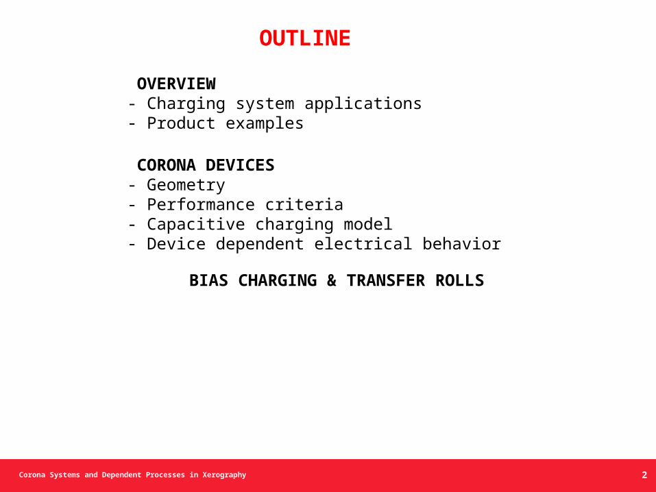
OVERVIEW- Charging system applications- Product examples
CORONA DEVICES- Geometry- Performance criteria- Capacitive charging model- Device dependent electrical behavior
BIAS CHARGING & TRANSFER ROLLS
OUTLINE
2
Corona Systems and Dependent Processes in Xerography 3
Corona Systems and Dependent Processes in Xerography
Charging System Applications
4
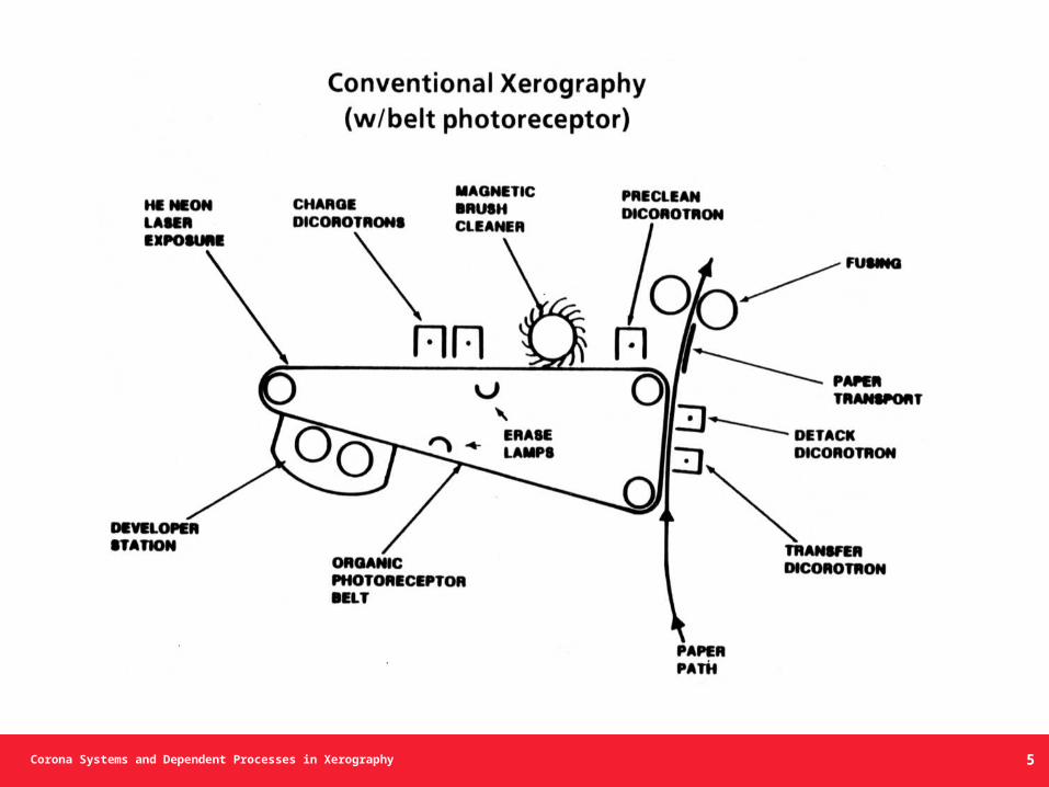
Corona Systems and Dependent Processes in Xerography 5
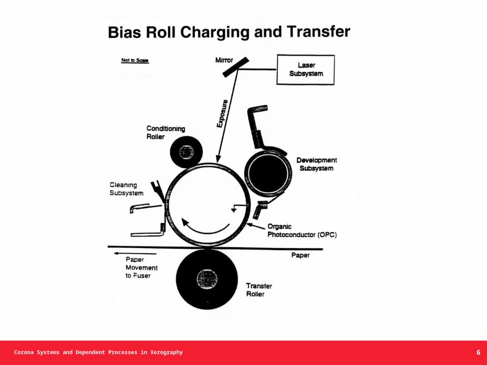
Corona Systems and Dependent Processes in Xerography 6
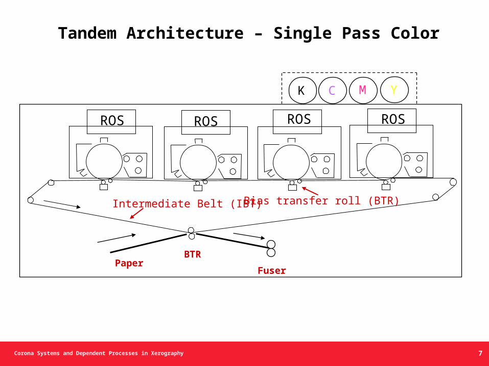
Corona Systems and Dependent Processes in Xerography
ROSROSROS ROS
Intermediate Belt (IBT) Bias transfer roll (BTR)
BTRPaper
Fuser
K C M Y
Tandem Architecture – Single Pass Color
7
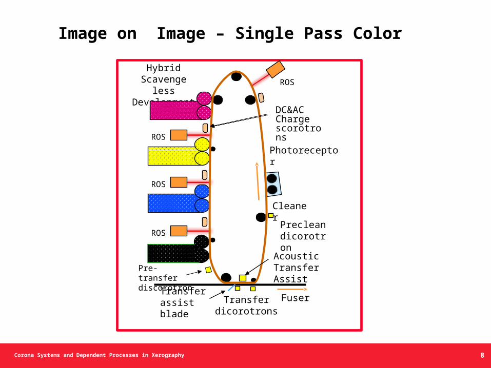
Corona Systems and Dependent Processes in Xerography
Image on Image – Single Pass Color
Hybrid Scavenge lessDevelopment
ROS
ROS
ROS
ROS
Cleaner
FuserTransferdicorotrons
Photoreceptor
Transfer assist blade
AcousticTransferAssist
Precleandicorotron
DC&AC Charge scorotrons
Pre-transferdiscorotron
8
Corona Systems and Dependent Processes in Xerography
Corona Devices and Characteristics
9
Corona Systems and Dependent Processes in Xerography 10
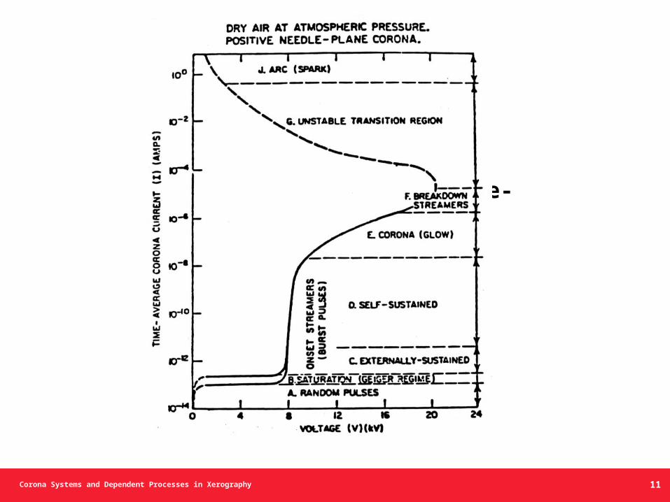
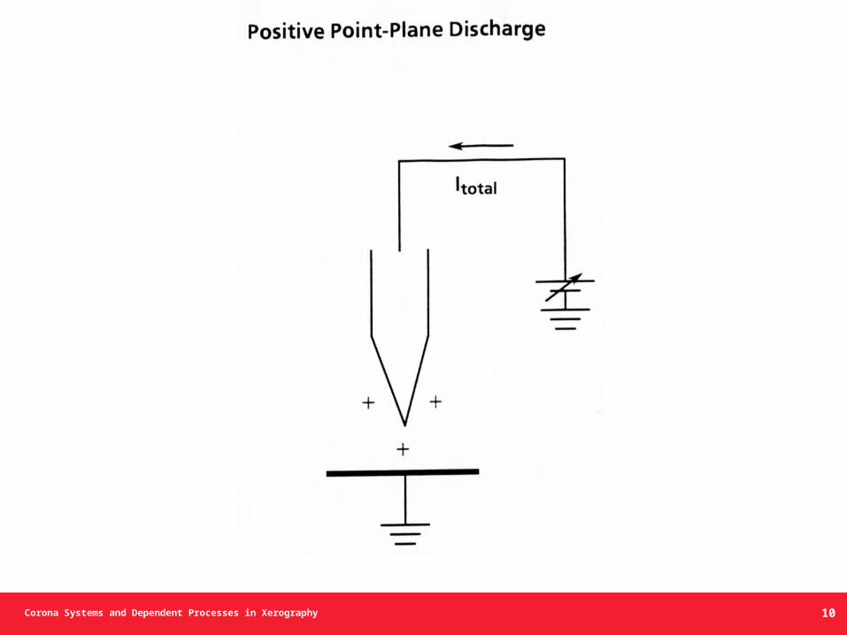
Corona Systems and Dependent Processes in Xerography
Dry Air at Atmospheric Pressure. Positive Needle-Plane Corona
11
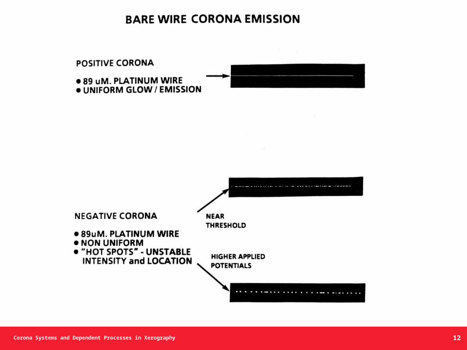
Corona Systems and Dependent Processes in Xerography
BareWire Corona Emission
12
Corona Systems and Dependent Processes in Xerography
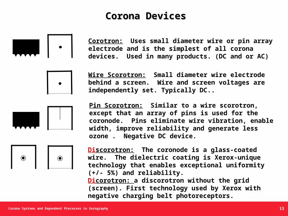
Wire Scorotron: Small diameter wire electrode behind a screen. Wire and screen voltages are independently set. Typically DC..
Pin Scorotron: Similar to a wire scorotron, except that an array of pins is used for the coronode. Pins eliminate wire vibration, enable width, improve reliability and generate less ozone . Negative DC device.
Discorotron: The coronode is a glass-coated wire. The dielectric coating is Xerox-unique technology that enables exceptional uniformity (+/- 5%) and reliability.Dicorotron: a discorotron without the grid (screen). First technology used by Xerox with negative charging belt photoreceptors.
Corona DevicesCorona Devices
Corotron: Uses small diameter wire or pin array electrode and is the simplest of all corona devices. Used in many products. (DC and or AC)
13
Corona Systems and Dependent Processes in Xerography
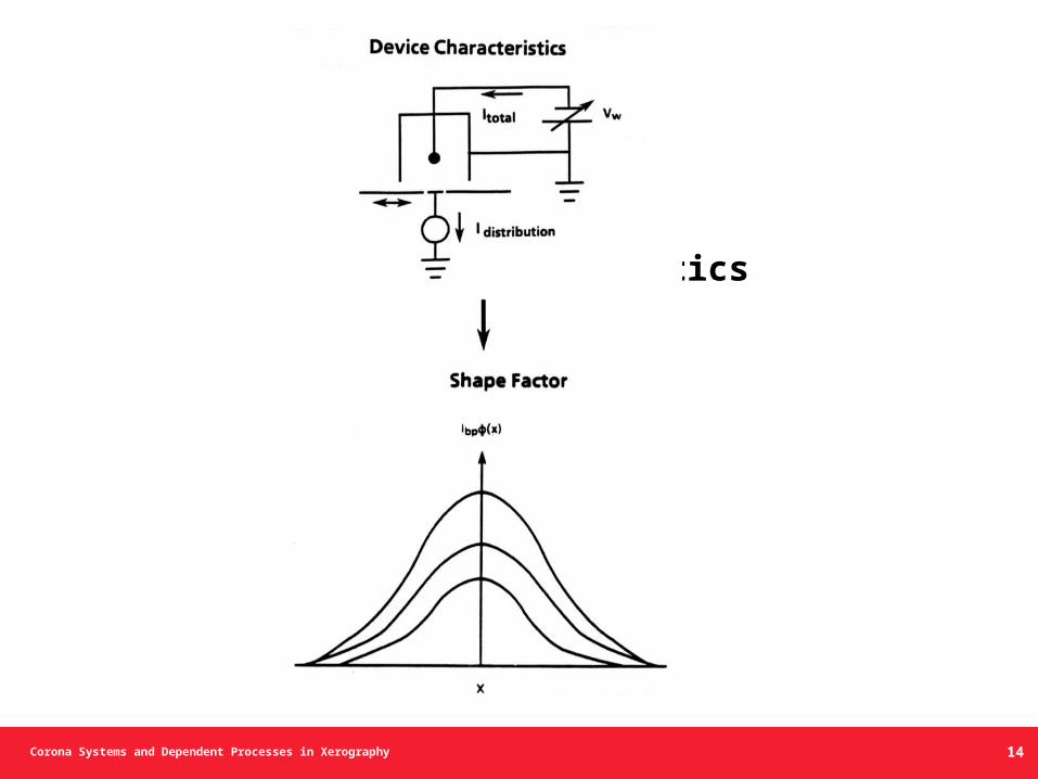
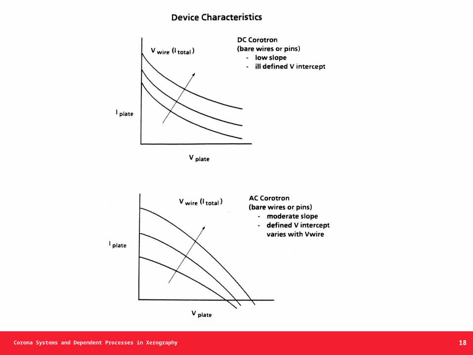
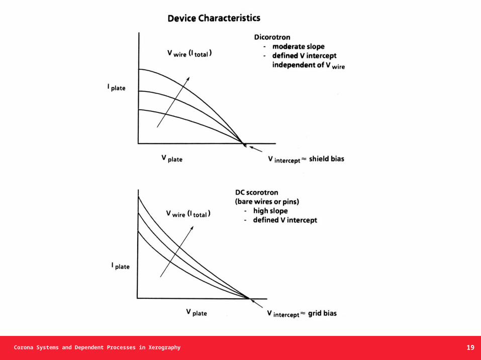
Device Characteristics
Shape Factor
14
Corona Systems and Dependent Processes in Xerography
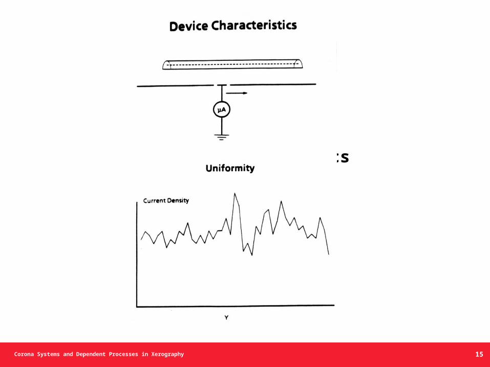
Device Characteristics Uniformity
15
Corona Systems and Dependent Processes in Xerography
I total
I shield
I plate
V plate
Vc
Ipla
te/L
(leng
th)
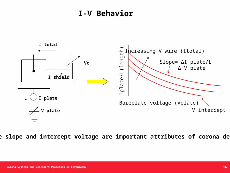
Bareplate voltage (Vplate)
Increasing V wire (Itotal)
Slope= ΔI plate/L Δ V plate
V intercept
• The slope and intercept voltage are important attributes of corona devices.
I-V Behavior
16
Corona Systems and Dependent Processes in Xerography
Corona Devices and Characteristics
Capacitive Charging Model
17
Corona Systems and Dependent Processes in Xerography 18
Corona Systems and Dependent Processes in Xerography 19
Corona Systems and Dependent Processes in Xerography 20
Corona Systems and Dependent Processes in Xerography
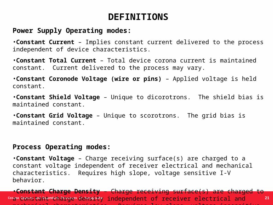
DEFINITIONS
Power Supply Operating modes:
•Constant Current – Implies constant current delivered to the process independent of device characteristics.
•Constant Total Current – Total device corona current is maintained constant. Current delivered to the process may vary.
•Constant Coronode Voltage (wire or pins) – Applied voltage is held constant.
•Constant Shield Voltage – Unique to dicorotrons. The shield bias is maintained constant.
•Constant Grid Voltage – Unique to scorotrons. The grid bias is maintained constant.
Process Operating modes:
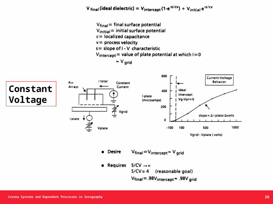
•Constant Voltage – Charge receiving surface(s) are charged to a constant voltage independent of receiver electrical and mechanical characteristics. Requires high slope, voltage sensitive I-V behavior.
•Constant Charge Density – Charge receiving surface(s) are charged to a constant charge density independent of receiver electrical and mechanical characteristics. Requires low slope, voltage insensitive I-V behavior.
21
Corona Systems and Dependent Processes in Xerography
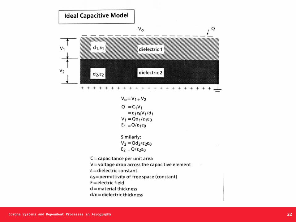
Ideal Capacitive Model
22
Corona Systems and Dependent Processes in Xerography
I total
I plate
V plate
Vc
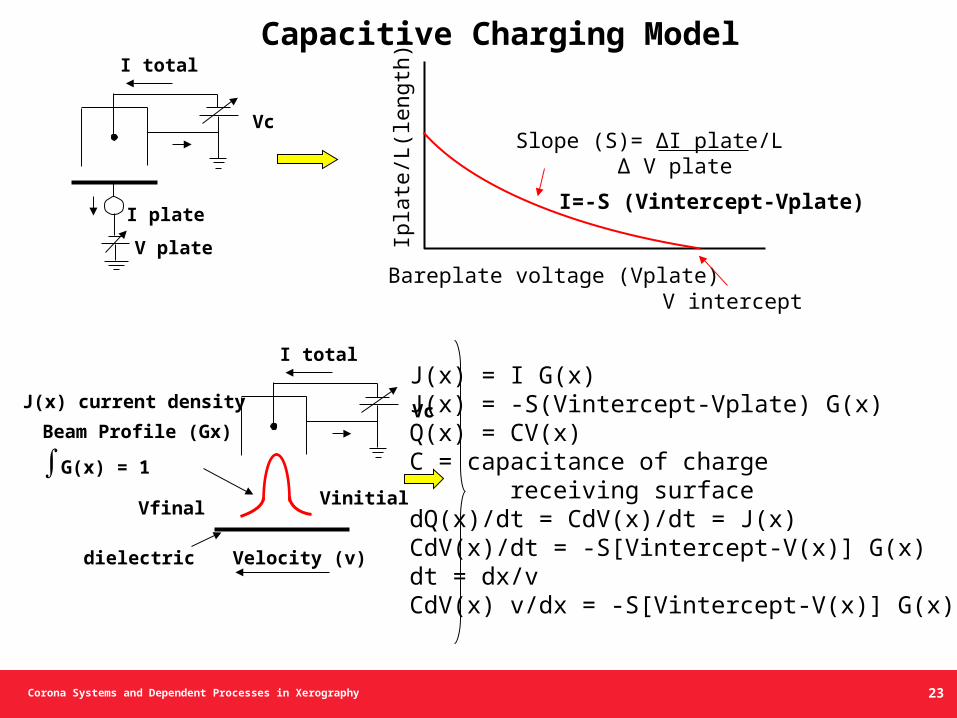
Capacitive Charging Model
I total
Vc
Vfinal Vinitial
dielectric Velocity (v)
J(x) current density
Beam Profile (Gx)
∫G(x) = 1
Ipla
te/L
(leng
th)
Bareplate voltage (Vplate)
Slope (S)= ΔI plate/L Δ V plate
V intercept
I=-S (Vintercept-Vplate)
J(x) = I G(x)J(x) = -S(Vintercept-Vplate) G(x)Q(x) = CV(x)C = capacitance of charge receiving surfacedQ(x)/dt = CdV(x)/dt = J(x)CdV(x)/dt = -S[Vintercept-V(x)] G(x)dt = dx/vCdV(x) v/dx = -S[Vintercept-V(x)] G(x)
23
Corona Systems and Dependent Processes in Xerography
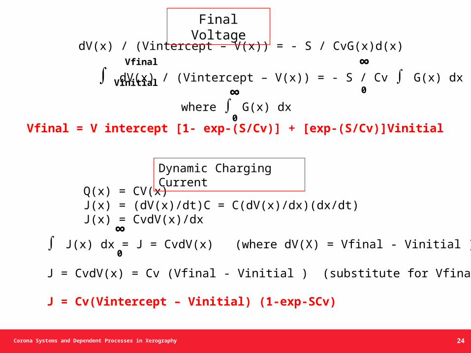
dV(x) / (Vintercept – V(x)) = - S / CvG(x)d(x)
∫ dV(x) / (Vintercept – V(x)) = - S / Cv ∫ G(x) dx
Vfinal
Vinitial
∞
0
where ∫ G(x) dx0
∞
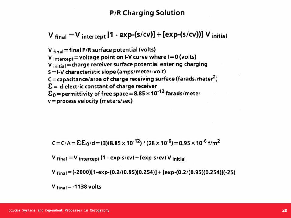
Vfinal = V intercept [1- exp-(S/Cv)] + [exp-(S/Cv)]Vinitial
Q(x) = CV(x)J(x) = (dV(x)/dt)C = C(dV(x)/dx)(dx/dt)J(x) = CvdV(x)/dx
∫ J(x) dx = J = CvdV(x) (where dV(X) = Vfinal - Vinitial )
J = CvdV(x) = Cv (Vfinal - Vinitial ) (substitute for Vfinal)
J = Cv(Vintercept – Vinitial) (1-exp-SCv)
0
∞
Dynamic Charging Current
Final Voltage
24
Corona Systems and Dependent Processes in Xerography
Photoreceptor Charging
and
Sample Calculations
25
Corona Systems and Dependent Processes in Xerography
Constant Voltage
26
Corona Systems and Dependent Processes in Xerography 27
Corona Systems and Dependent Processes in Xerography 28
Corona Systems and Dependent Processes in Xerography
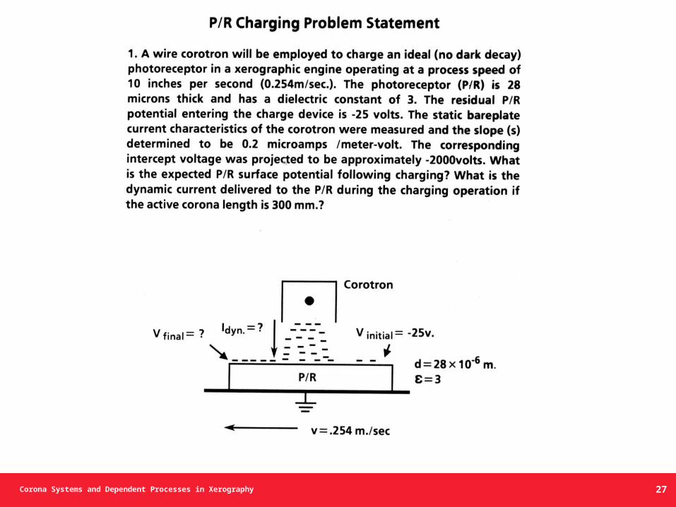
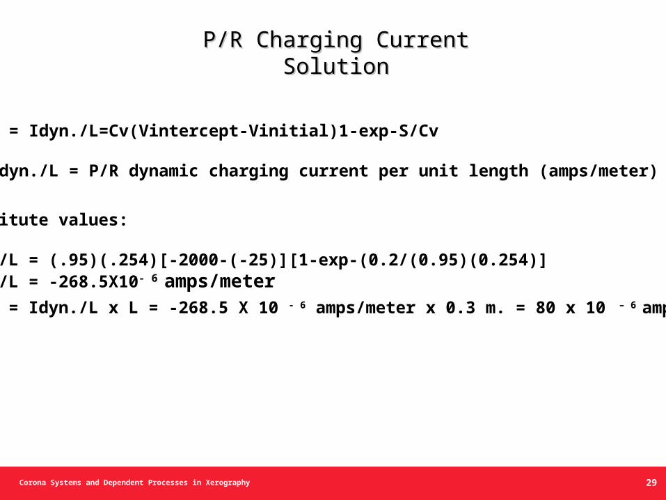
P/R Charging Current SolutionP/R Charging Current Solution
J = Idyn./L=Cv(Vintercept-Vinitial)1-exp-S/Cv
Idyn./L = P/R dynamic charging current per unit length (amps/meter)
Substitute values:
Idyn./L = (.95)(.254)[-2000-(-25)][1-exp-(0.2/(0.95)(0.254)]Idyn./L = -268.5X10- 6 amps/meter
Idyn. = Idyn./L x L = -268.5 X 10 - 6 amps/meter x 0.3 m. = 80 x 10 – 6 amps
29
Corona Systems and Dependent Processes in Xerography
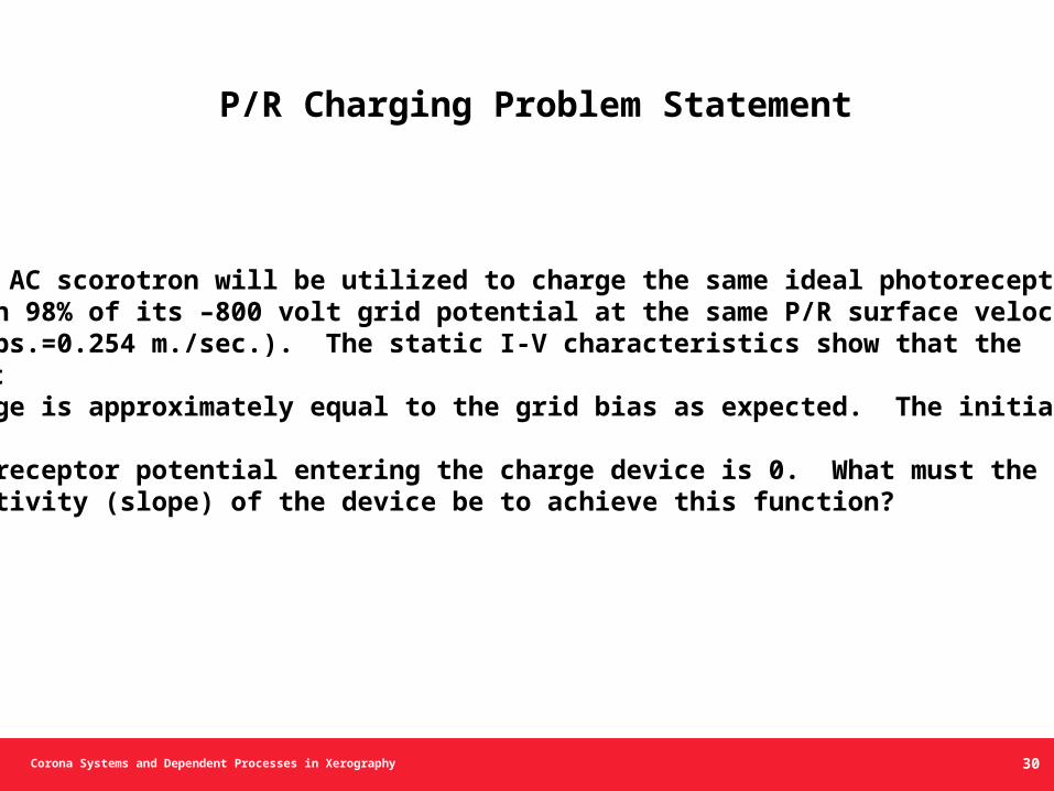
2. An AC scorotron will be utilized to charge the same ideal photoreceptor to
within 98% of its –800 volt grid potential at the same P/R surface velocity (10 ips.=0.254 m./sec.). The static I-V characteristics show that the
intercept voltage is approximately equal to the grid bias as expected. The initial
residual photoreceptor potential entering the charge device is 0. What must the
voltage sensitivity (slope) of the device be to achieve this function?
P/R Charging Problem Statement
30
Corona Systems and Dependent Processes in Xerography
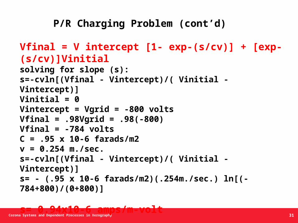
Vfinal = V intercept [1- exp-(s/cv)] + [exp-(s/cv)]Vinitialsolving for slope (s):s=-cvln[(Vfinal - Vintercept)/( Vinitial - Vintercept)]Vinitial = 0Vintercept = Vgrid = -800 voltsVfinal = .98Vgrid = .98(-800)Vfinal = -784 voltsC = .95 x 10-6 farads/m2v = 0.254 m./sec.s=-cvln[(Vfinal - Vintercept)/( Vinitial - Vintercept)]s= - (.95 x 10-6 farads/m2)(.254m./sec.) ln[(-784+800)/(0+800)]
s= 0.94x10⁻⁶ amps/m-volt
P/R Charging Problem (cont’d)
31
Corona Systems and Dependent Processes in Xerography
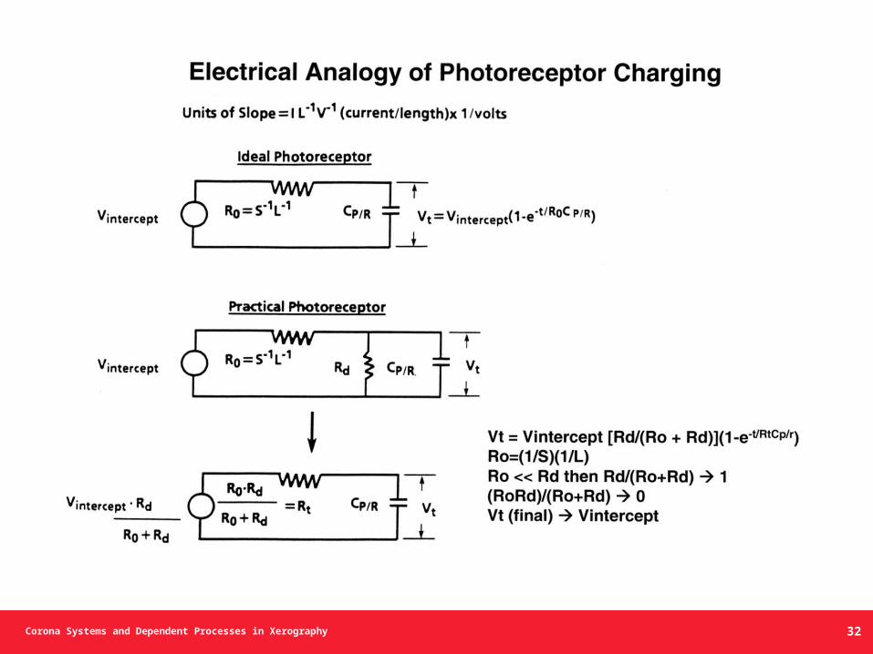
Electrical Analogy of Photoreceptor Charging
32
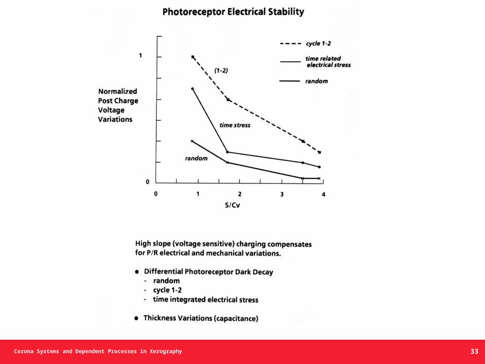
Corona Systems and Dependent Processes in Xerography 33
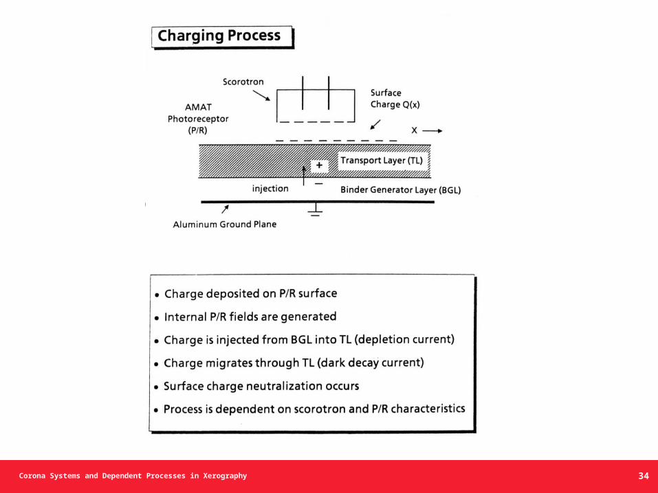
Corona Systems and Dependent Processes in Xerography
Charging Process
34
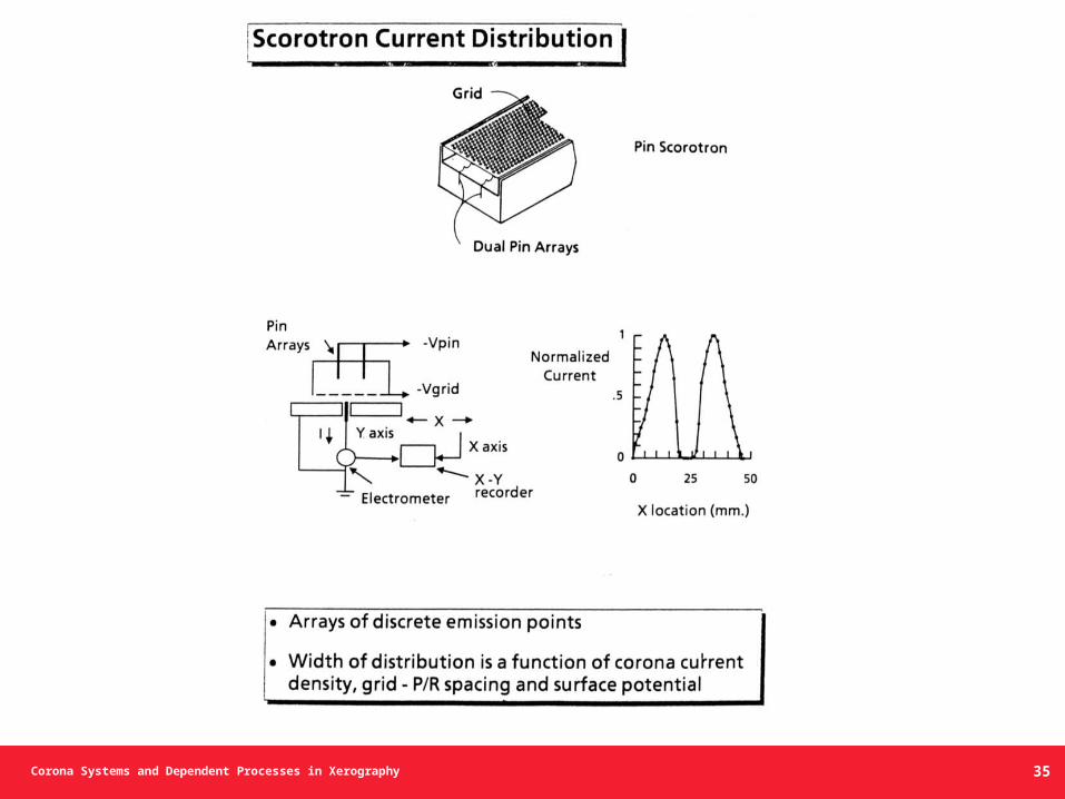
Corona Systems and Dependent Processes in Xerography 35
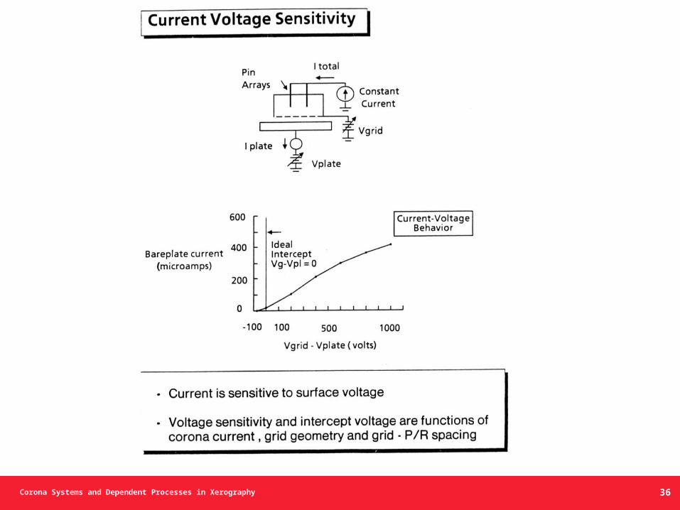
Corona Systems and Dependent Processes in Xerography
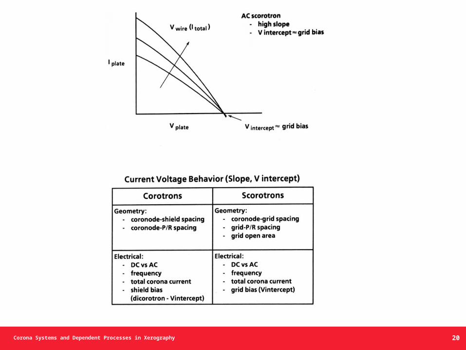
Current Voltage Sensitivity
36
Corona Systems and Dependent Processes in Xerography
Equivalent Circuits
and
Corotron Current-Voltage Behavior
37
Corona Systems and Dependent Processes in Xerography
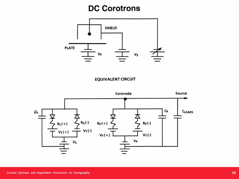
DC Corotrons
38
Corona Systems and Dependent Processes in Xerography
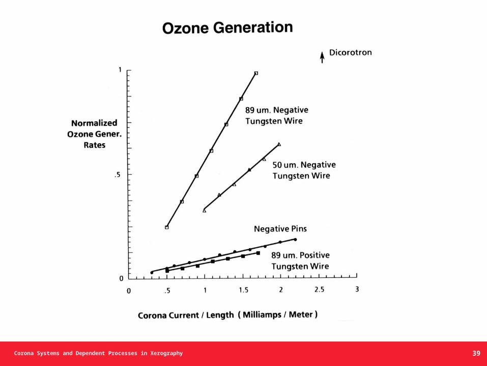
Ozone Generation
39
Corona Systems and Dependent Processes in Xerography
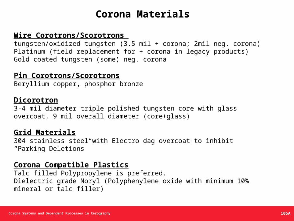
Corona Materials
Wire Corotrons/Scorotrons tungsten/oxidized tungsten (3.5 mil + corona; 2mil neg. corona)Platinum (field replacement for + corona in legacy products)Gold coated tungsten (some) neg. corona
Pin Corotrons/ScorotronsBeryllium copper, phosphor bronze
Dicorotron3-4 mil diameter triple polished tungsten core with glass overcoat, 9 mil overall diameter (core+glass)
Grid Materials304 stainless steel with Electro dag overcoat to inhibit “Parking Deletions”
Corona Compatible PlasticsTalc filled Polypropylene is preferred.Dielectric grade Noryl (Polyphenylene oxide with minimum 10% mineral or talc filler)
105A
Corona Systems and Dependent Processes in Xerography
Bias Charging and Transfer Rolls
(BCR / BTR)
106
Corona Systems and Dependent Processes in Xerography
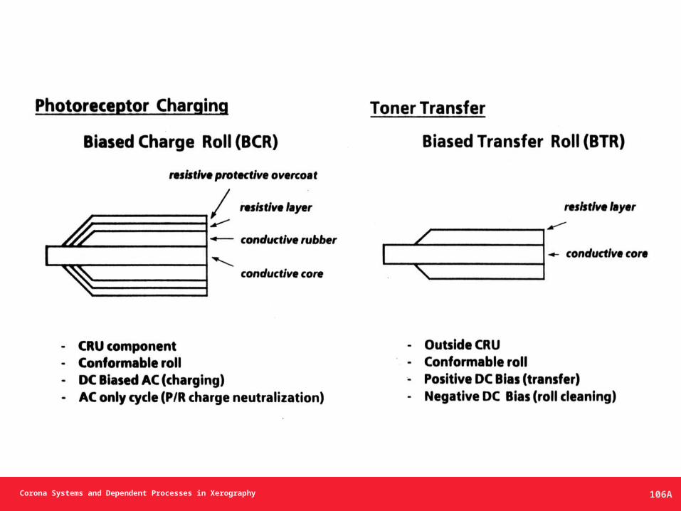
Photoreceptor Charging
106A
Corona Systems and Dependent Processes in Xerography
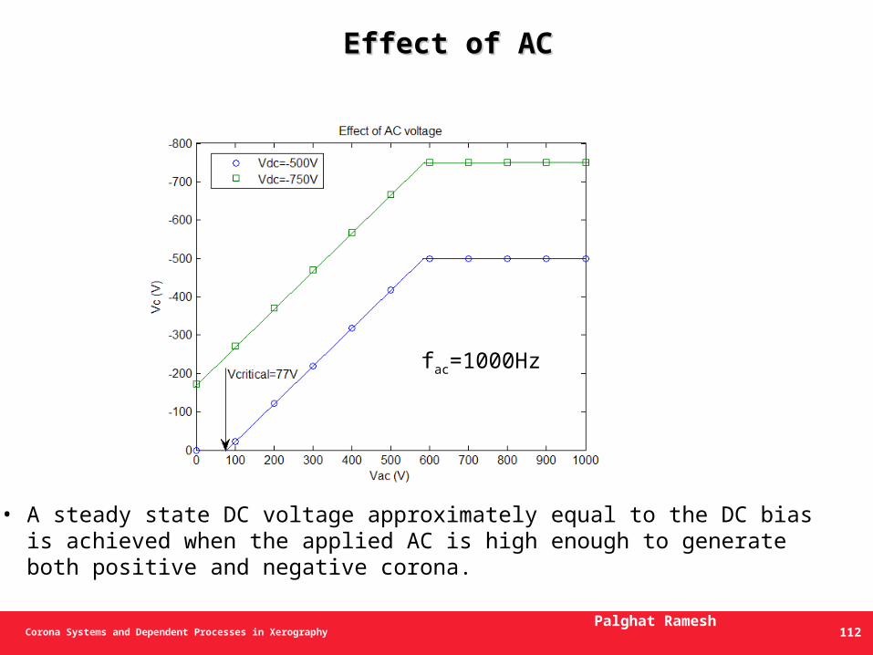
Effect of ACEffect of AC
fac=1000Hz
• A steady state DC voltage approximately equal to the DC bias is achieved when the applied AC is high enough to generate both positive and negative corona.
Palghat Ramesh112
Corona Systems and Dependent Processes in Xerography
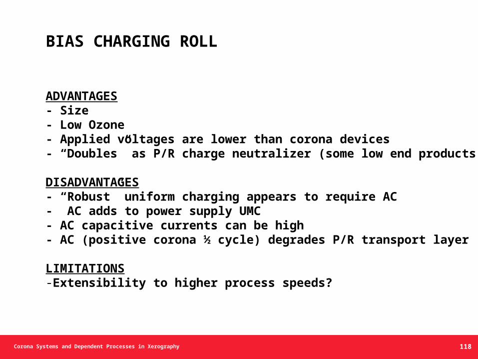
BIAS CHARGING ROLL
ADVANTAGES- Size- Low Ozone- Applied voltages are lower than corona devices- “Doubles” as P/R charge neutralizer (some low end products)
DISADVANTAGES- “Robust” uniform charging appears to require AC- AC adds to power supply UMC- AC capacitive currents can be high- AC (positive corona ½ cycle) degrades P/R transport layer
LIMITATIONS-Extensibility to higher process speeds?
118
Corona Systems and Dependent Processes in Xerography
EXTERNAL ARTICLES• “Pin” Models – (K. Pietrowski, Walsh)• Corona Charging – (K. Pietrowski, et al)• Corona Physics – (C. Gallo, W. Lama)
EXTERNAL REFERENCES• Williams, E.M. (1984), Physics and Technology of Xerographic Processes, John Wiley and Sons, New York.• Schaffert, R.M. (1975), Electrophotography, 5th ed., Focal Press, London.
REFERENCES (cont’d.)
138