Prepared For: Cornell University Human Resources Veteran ...
CornellEnergy
Resources
Cornell UniversityEnergy & Sustainability
ThE CEnTRal EnERgy PlanT
Safety ReliabilityEfficiency
INTRODUCTION
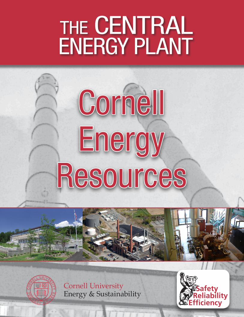
The Central Energy Plant (CEP) at Cornell University provides all the centrally produced power and district energy services such as steam and chilled water. The facilities associated with the CEP are the Central Heating Plant (CHP), Combined Heat & Power Plant (CCHPP), Co-generation facility (Co-Gen), Lake Source Cooling (LSC), Chilled Water Plant 3 (CWP3), Water Treatment Plant (WTP), Steam Condenser Building (SCB), and Maple Avenue Substation (MAS). LSC is located at the shore of Cayuga Lake; otherwise the CEP facilities are located at the utilities complex on Rt 366 on the south edge of campus.
Cornell is one of the few educational institutions with full metering of all individual building energy streams in addition to all central plant equipment. The plant accounts fund all costs associated with building metering. The campus usage of energy is grouped into major customer categories and is for the most part centrally managed. All campus central utility connected loads are grouped into three major accounts and three minor accounts associated with professional schools. The three major accounts include all academic/research/teaching buildings (two accounts) and the campus life functions (one account). The three professional schools account for about 3% and campus life about 10% of use, although they together represent about one third of the space. Campus energy use is heavily driven by the research mission (ventilation and electric load), accounting for at least half of total use.
CCHPP
SCB
WTP CHP
CWP3
Substation
Co-gen
The Cornell utility systems, building energy costs, and conservation efforts are managed through a detailed enterprise cost accounting system that totals about $60 million annually for Utilities and Energy Conservation. About 60 full and part time staff (about half in CEP) manages, operates, and maintains the various enterprise functions. A detailed five year plan guides capital and operational budgets.
Cornell University is an energy intensive operation requiring ~ 2.5 trillion BTUs/year in fuel and electricity. Some generalized metrics associated with energy use at Cornell are as follows: Power
~36 MW peak demand ~250,000,000 kwh used annually by campus ~35,000,000 kwh is grid purchased through the university substation ~215,000,000 kwh is self-produced by on-campus facilities
~180,000,000 kwh is produced by the CCHPP ~30,000,000 kwh is produced by Co-Gen ~5,000,000 kwh is produced by the campus hydroelectric plant on Fall Creek
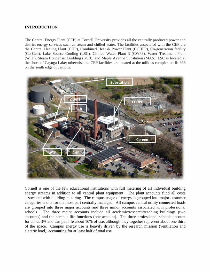
Heat ~1,200,000 thousand pounds of steam are produced each year
~400 thousand lbs/hr peak steam demand ~137 thousand lbs/hr average steam demand ~55 thousand lbs/hr minimum (summer) demand
~2,700,000 dekatherms of natural gas are combusted annually ~75% is the annual thermodynamic efficiency of centralized heat and power production
Cooling ~45,000,000 ton-hrs of cooling are produced each year ~22,000 tons are the peak cooling demand (summer) ~2,500 is the minimum cooling demand (winter) ~1.3 kwh/ton-hr is the average annual efficiency which is one of the most efficient in the world.
District heating serves approximately 150 buildings (14 million sqft) and is supplied via an underground steam distribution system consisting of 13.4 miles of steam line, 12.4 miles of condensate line, and 165 vaults or manholes. District cooling serves 75 buildings totaling over 4 million square feet of air conditioned space, about 40% of the core campus. The underground piping network consists of over fifteen (15) miles of underground direct buried piping with a

volume of approximately 3.0 million gallons. A 4.5 million gallon stratified thermal storage tank increases the total system volume to 7.5 million gallons.
HEAT & POWER PRODUCTION
A Brief History of District Heating at Cornell
The Cornell CHP provides steam to the campus community for space heating, hot water, and research along with cogenerated electricity from load following backpressure steam turbine electric generators (STGs). Approximately 150 buildings (14 million sqft) are heated via an underground steam distribution system. The west half of the current CHP structure was built in 1922 to replace old facilities. Originally, the CHP included four B&W three drum boilers fueled by Pennsylvania anthracite coal (Boilers 1-4). Two additional boilers (6 and 7) were added in 1930 to the east side; these were upgraded with superheaters in 1940.
In 1949, stoker Boiler 8 was added, fueled with buckwheat anthracite. The boiler was rated at 900 psig, but was brought on line at 200 psig when plans to utilize high pressure steam for electricity production were abandoned. In 1959, Boilers 1 and 2 were replaced with two drum units burning bituminous coal. Superheaters were installed in these two boilers and the feed water system, de-aerating feed tank, surge tank and piping system were all upgraded.
In 1969, Boilers 6 and 7 were replaced with dual fuel capability units. In 1970, Boilers 3 and 4 were replaced with Boiler 5, a dual fuel unit permitted only for gas. In 1972, Hurricane Agnes washed out the rail line formerly used for coal deliveries. At that time, oil was the primary fuel for the entire CHP, and the rail line was abandoned. The following year, the oil embargo caused oil prices to skyrocket. The University elected to rehabilitate Boiler 8, adding a new superheater and economizer and converting it to burn bituminous coal in 1976. At the same time, the coal handling system was modernized.
However, the former rail line was no longer directly accessible to the CHP. As a result, all coal deliveries up until 2011 where by truck from the Monaca, Pennsylvania barge terminal or from a rail terminal in Ithaca.
In response to an increase in steam load, Boiler 2 was converted to oil in 1978. This unit has been used sparingly as a peaking unit, and is at the end of its useful life. In 1981, after a period of skyrocketing oil prices, Boiler 1 was replaced with a stoker coal unit. Major improvements at the CHP were implemented in 1986-88 following extensive planning efforts. Cogeneration was initiated with the installation of two new backpressure STGs, TG-1 (1.7 MW) and TG-2 (5.8 MW). Other upgrades included a new economizer and full fabric filter (baghouse) for Boiler 1, a new superheater for Boiler 8, new distributed digital controls systems, and electrical systems.
In the early 1990s, Boilers 6 and 7 were replaced with high efficiency dual fuel packaged boilers. In 1997, a baghouse was added to Boiler 8 with a new turbine-driven induced draft fan. A new plant head end SCADA system was implemented in 1999-2000. Finally, in 2001, continuous emission monitors (CEM) for NOx were installed on Boiler 6 and 7 to comply with Environmental Protection Agency (EPA) Title V air emission standards and replace the predictive system that had been used since 1996.
Cornell has on-site fuel storage for coal and #2 ULSD fuel oil. The capacity of the coal storage pile is approximately 18,000 tons. The capacity of the oil storage tank is ~ 670,000 gallons. The coal storage pile, as well as the coal conveyers and leachate collection pit was modernized in 1976. The coal conveyor was replaced in 2007. The fuel oil tank was constructed in 1969 as a 1 million gallon storage facility to store #6 oil. The tank was completely renewed with new containment and reduced in capacity in 2007. The entire oil offloading and conveyance system was also replaced. On February 22, 2007, Cornell President David J. Skorton signed the American College and University Presidents Climate Commitment. In doing so, President Skorton pledged to develop a plan for Cornell that strives for climate neutrality with respect to greenhouse gas (GHG) emissions for the Ithaca, NY campus. As part of this commitment, Cornell ceased combustion of coal in early 2011 at which time Boilers 1 and 8 where retired from service.
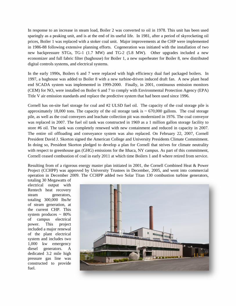
Resulting from of a rigorous energy master plan initiated in 2001, the Cornell Combined Heat & Power Project (CCHPP) was approved by University Trustees in December, 2005, and went into commercial operation in December 2009. The CCHPP added two Solar Titan 130 combustion turbine generators, totaling 30 Megawatts of electrical output with Rentech heat recovery steam generators, totaling 300,000 lbs/hr of steam generation, at the current CHP. This system produces ~ 80% of campus electrical power. This project included a major renewal of the plant electrical system and includes two 1,000 kw emergency diesel generators. A dedicated 3.2 mile high pressure gas line was constructed to provide fuel.
Starting in 2009, a renewal project for the water treatment plant (WTP) was undertaken to improve reliability and quality of the boiler make-up system. New softeners where constructed in in the SCB during 2009 which allowed for mechanical demolition of the existing WTP. In 2010, a new reverse osmosis system was installed in the WTP thus greatly improving make-up water quality.
Thermal Energy Production at the CEP
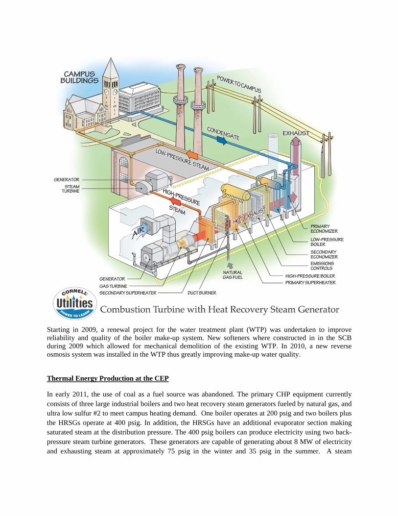
In early 2011, the use of coal as a fuel source was abandoned. The primary CHP equipment currently consists of three large industrial boilers and two heat recovery steam generators fueled by natural gas, and ultra low sulfur #2 to meet campus heating demand. One boiler operates at 200 psig and two boilers plus the HRSGs operate at 400 psig. In addition, the HRSGs have an additional evaporator section making saturated steam at the distribution pressure. The 400 psig boilers can produce electricity using two back-pressure steam turbine generators. These generators are capable of generating about 8 MW of electricity and exhausting steam at approximately 75 psig in the winter and 35 psig in the summer. A steam
distribution system delivers the exhaust steam from the turbines to campus facilities, with no supplemental condensing. Nearly all steam production is used to cogenerate electricity.
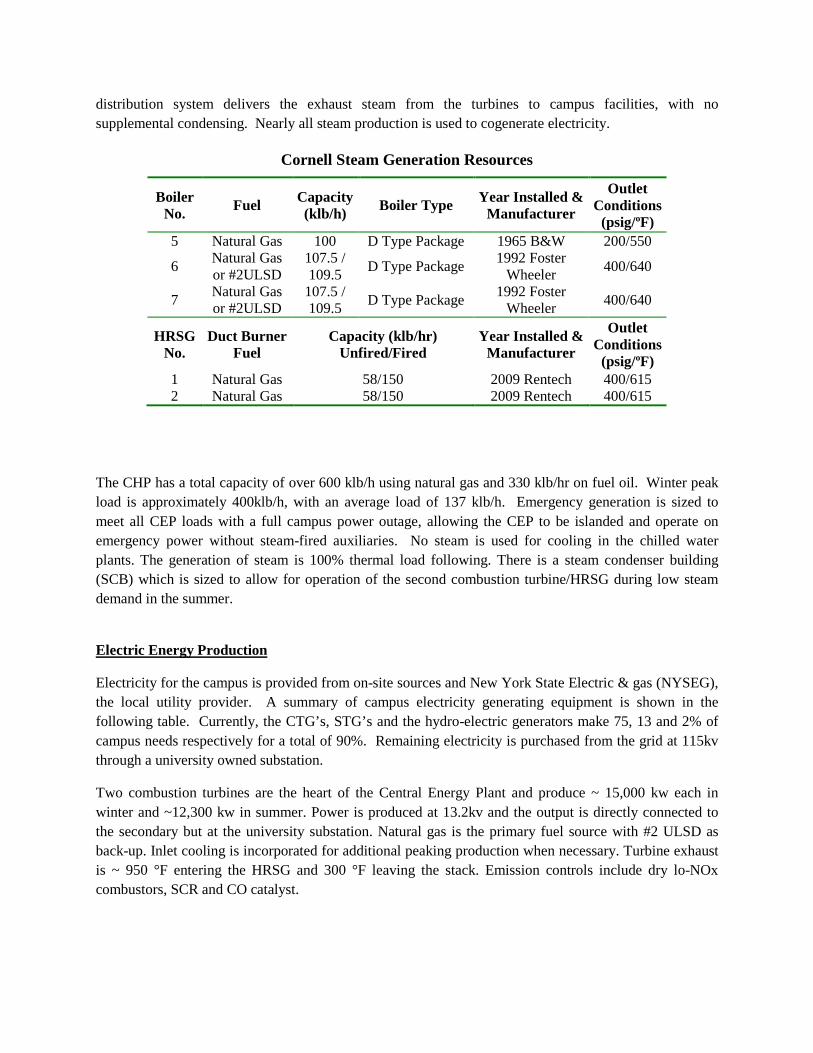
Cornell Steam Generation Resources
Boiler No. Fuel Capacity
(klb/h) Boiler Type Year Installed & Manufacturer
Outlet Conditions
(psig/ºF) 5 Natural Gas 100 D Type Package 1965 B&W 200/550
6 Natural Gas or #2ULSD
107.5 / 109.5 D Type Package 1992 Foster
Wheeler 400/640
7 Natural Gas or #2ULSD
107.5 / 109.5 D Type Package 1992 Foster
Wheeler 400/640
HRSG No.
Duct Burner Fuel
Capacity (klb/hr) Unfired/Fired
Year Installed & Manufacturer
Outlet Conditions
(psig/ºF) 1 Natural Gas 58/150 2009 Rentech 400/615 2 Natural Gas 58/150 2009 Rentech 400/615
The CHP has a total capacity of over 600 klb/h using natural gas and 330 klb/hr on fuel oil. Winter peak load is approximately 400klb/h, with an average load of 137 klb/h. Emergency generation is sized to meet all CEP loads with a full campus power outage, allowing the CEP to be islanded and operate on emergency power without steam-fired auxiliaries. No steam is used for cooling in the chilled water plants. The generation of steam is 100% thermal load following. There is a steam condenser building (SCB) which is sized to allow for operation of the second combustion turbine/HRSG during low steam demand in the summer.
Electric Energy Production
Electricity for the campus is provided from on-site sources and New York State Electric & gas (NYSEG), the local utility provider. A summary of campus electricity generating equipment is shown in the following table. Currently, the CTG’s, STG’s and the hydro-electric generators make 75, 13 and 2% of campus needs respectively for a total of 90%. Remaining electricity is purchased from the grid at 115kv through a university owned substation.
Two combustion turbines are the heart of the Central Energy Plant and produce ~ 15,000 kw each in winter and ~12,300 kw in summer. Power is produced at 13.2kv and the output is directly connected to the secondary but at the university substation. Natural gas is the primary fuel source with #2 ULSD as back-up. Inlet cooling is incorporated for additional peaking production when necessary. Turbine exhaust is ~ 950 °F entering the HRSG and 300 °F leaving the stack. Emission controls include dry lo-NOx combustors, SCR and CO catalyst.
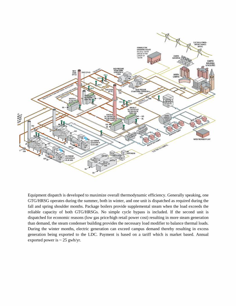
Equipment dispatch is developed to maximize overall thermodynamic efficiency. Generally speaking, one GTG/HRSG operates during the summer, both in winter, and one unit is dispatched as required during the fall and spring shoulder months. Package boilers provide supplemental steam when the load exceeds the reliable capacity of both GTG/HRSGs. No simple cycle bypass is included. If the second unit is dispatched for economic reasons (low gas price/high retail power cost) resulting in more steam generation than demand, the steam condenser building provides the necessary load modifier to balance thermal loads. During the winter months, electric generation can exceed campus demand thereby resulting in excess generation being exported to the LDC. Payment is based on a tariff which is market based. Annual exported power is ~ 25 gwh/yr.
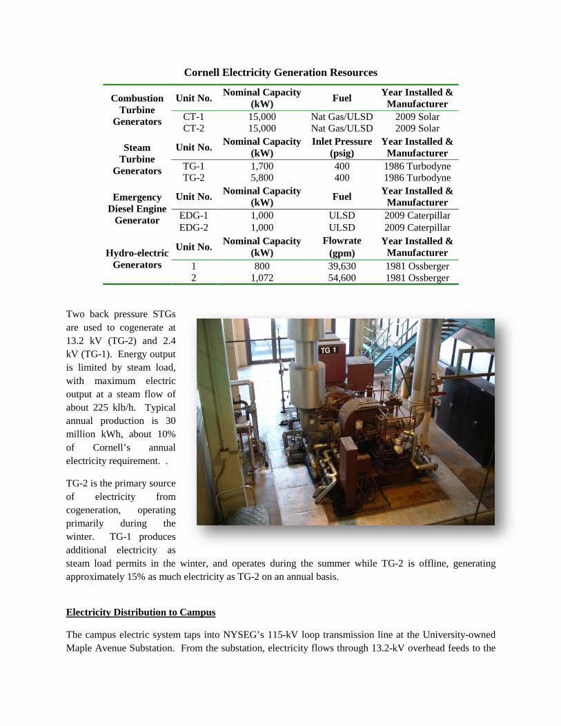
Cornell Electricity Generation Resources
Combustion Turbine
Generators
Unit No. Nominal Capacity (kW) Fuel Year Installed &
Manufacturer CT-1 15,000 Nat Gas/ULSD 2009 Solar CT-2 15,000 Nat Gas/ULSD 2009 Solar
Steam Turbine
Generators
Unit No. Nominal Capacity (kW)
Inlet Pressure (psig)
Year Installed & Manufacturer
TG-1 1,700 400 1986 Turbodyne TG-2 5,800 400 1986 Turbodyne
Emergency Diesel Engine
Generator
Unit No. Nominal Capacity (kW) Fuel Year Installed &
Manufacturer EDG-1 1,000 ULSD 2009 Caterpillar EDG-2 1,000 ULSD 2009 Caterpillar
Hydro-electric Generators
Unit No. Nominal Capacity (kW)
Flowrate (gpm)
Year Installed & Manufacturer
1 800 39,630 1981 Ossberger 2 1,072 54,600 1981 Ossberger
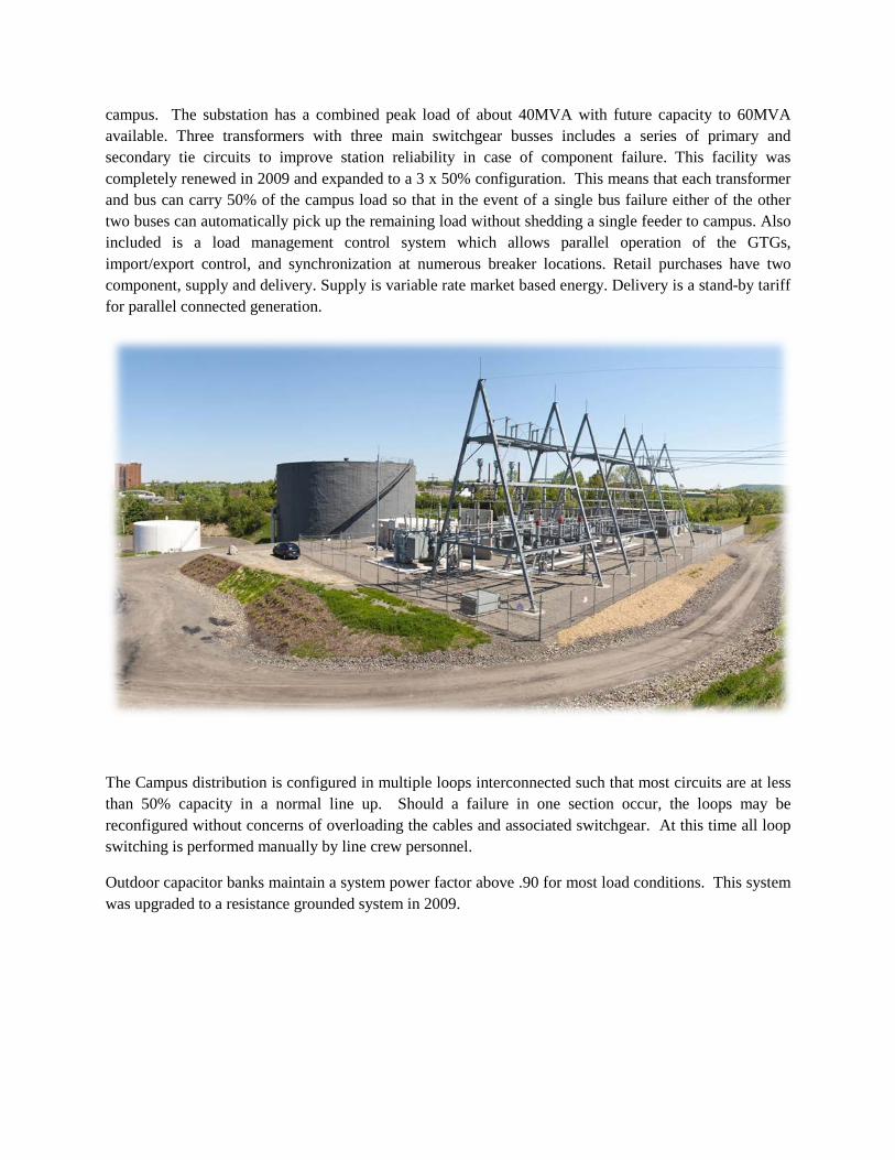
Two back pressure STGs are used to cogenerate at 13.2 kV (TG-2) and 2.4 kV (TG-1). Energy output is limited by steam load, with maximum electric output at a steam flow of about 225 klb/h. Typical annual production is 30 million kWh, about 10% of Cornell’s annual electricity requirement. .
TG-2 is the primary source of electricity from cogeneration, operating primarily during the winter. TG-1 produces additional electricity as steam load permits in the winter, and operates during the summer while TG-2 is offline, generating approximately 15% as much electricity as TG-2 on an annual basis.
Electricity Distribution to Campus
The campus electric system taps into NYSEG’s 115-kV loop transmission line at the University-owned Maple Avenue Substation. From the substation, electricity flows through 13.2-kV overhead feeds to the
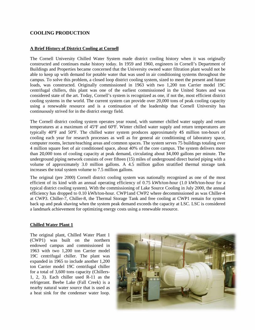
campus. The substation has a combined peak load of about 40MVA with future capacity to 60MVA available. Three transformers with three main switchgear busses includes a series of primary and secondary tie circuits to improve station reliability in case of component failure. This facility was completely renewed in 2009 and expanded to a 3 x 50% configuration. This means that each transformer and bus can carry 50% of the campus load so that in the event of a single bus failure either of the other two buses can automatically pick up the remaining load without shedding a single feeder to campus. Also included is a load management control system which allows parallel operation of the GTGs, import/export control, and synchronization at numerous breaker locations. Retail purchases have two component, supply and delivery. Supply is variable rate market based energy. Delivery is a stand-by tariff for parallel connected generation.
The Campus distribution is configured in multiple loops interconnected such that most circuits are at less than 50% capacity in a normal line up. Should a failure in one section occur, the loops may be reconfigured without concerns of overloading the cables and associated switchgear. At this time all loop switching is performed manually by line crew personnel.
Outdoor capacitor banks maintain a system power factor above .90 for most load conditions. This system was upgraded to a resistance grounded system in 2009.
COOLING PRODUCTION
A Brief History of District Cooling at Cornell
The Cornell University Chilled Water System made district cooling history when it was originally constructed and continues make history today. In 1959 and 1960, engineers in Cornell’s Department of Buildings and Properties became concerned that the University owned water filtration plant would not be able to keep up with demand for potable water that was used in air conditioning systems throughout the campus. To solve this problem, a closed loop district cooling system, sized to meet the present and future loads, was constructed. Originally commissioned in 1963 with two 1,200 ton Carrier model 19C centrifugal chillers, this plant was one of the earliest commissioned in the United States and was considered state of the art. Today, Cornell’s system is recognized as one, if not the, most efficient district cooling systems in the world. The current system can provide over 20,000 tons of peak cooling capacity using a renewable resource and is a continuation of the leadership that Cornell University has continuously strived for in the district energy field.
The Cornell district cooling system operates year round, with summer chilled water supply and return temperatures at a maximum of 45ºF and 60ºF. Winter chilled water supply and return temperatures are typically 40ºF and 50ºF. The chilled water system produces approximately 45 million ton-hours of cooling each year for research processes as well as for general air conditioning of laboratory space, computer rooms, lecture/teaching areas and common spaces. The system serves 75 buildings totaling over 4 million square feet of air conditioned space, about 40% of the core campus. The system delivers more than 20,000 tons of cooling capacity at peak demand, circulating about 34,000 gallons per minute. The underground piping network consists of over fifteen (15) miles of underground direct buried piping with a volume of approximately 3.0 million gallons. A 4.5 million gallon stratified thermal storage tank increases the total system volume to 7.5 million gallons.
The original (pre 2000) Cornell district cooling system was nationally recognized as one of the most efficient of its kind with an annual operating efficiency of 0.75 kWh/ton-hour (1.0 kWh/ton-hour for a typical district cooling system). With the commissioning of Lake Source Cooling in July 2000, the annual efficiency has dropped to 0.10 kWh/ton-hour. CWP1and CWP2 where decommissioned as was Chiller-4 at CWP3. Chiller-7, Chiller-8, the Thermal Storage Tank and free cooling at CWP1 remain for system back up and peak shaving when the system peak demand exceeds the capacity at LSC. LSC is considered a landmark achievement for optimizing energy costs using a renewable resource.
Chilled Water Plant 1
The original plant, Chilled Water Plant 1 (CWP1) was built on the northern endowed campus and commissioned in 1963 with two 1,200 ton Carrier model 19C centrifugal chiller. The plant was expanded in 1965 to include another 1,200 ton Carrier model 19C centrifugal chiller for a total of 3,600 tons capacity (Chillers-1, 2, 3). Each chiller used R-11 as the refrigerant. Beebe Lake (Fall Creek) is a nearby natural water source that is used as a heat sink for the condenser water loop.
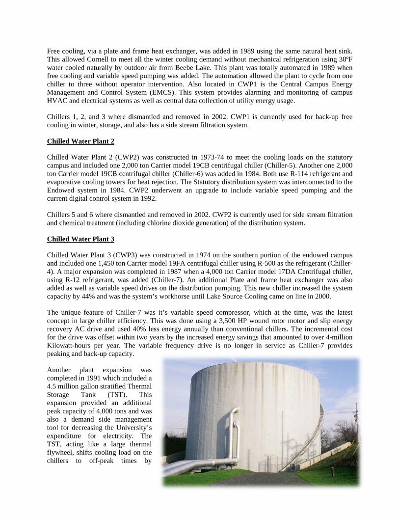
Free cooling, via a plate and frame heat exchanger, was added in 1989 using the same natural heat sink. This allowed Cornell to meet all the winter cooling demand without mechanical refrigeration using 38ºF water cooled naturally by outdoor air from Beebe Lake. This plant was totally automated in 1989 when free cooling and variable speed pumping was added. The automation allowed the plant to cycle from one chiller to three without operator intervention. Also located in CWP1 is the Central Campus Energy Management and Control System (EMCS). This system provides alarming and monitoring of campus HVAC and electrical systems as well as central data collection of utility energy usage.
Chillers 1, 2, and 3 where dismantled and removed in 2002. CWP1 is currently used for back-up free cooling in winter, storage, and also has a side stream filtration system.
Chilled Water Plant 2
Chilled Water Plant 2 (CWP2) was constructed in 1973-74 to meet the cooling loads on the statutory campus and included one 2,000 ton Carrier model 19CB centrifugal chiller (Chiller-5). Another one 2,000 ton Carrier model 19CB centrifugal chiller (Chiller-6) was added in 1984. Both use R-114 refrigerant and evaporative cooling towers for heat rejection. The Statutory distribution system was interconnected to the Endowed system in 1984. CWP2 underwent an upgrade to include variable speed pumping and the current digital control system in 1992.
Chillers 5 and 6 where dismantled and removed in 2002. CWP2 is currently used for side stream filtration and chemical treatment (including chlorine dioxide generation) of the distribution system.
Chilled Water Plant 3
Chilled Water Plant 3 (CWP3) was constructed in 1974 on the southern portion of the endowed campus and included one 1,450 ton Carrier model 19FA centrifugal chiller using R-500 as the refrigerant (Chiller-4). A major expansion was completed in 1987 when a 4,000 ton Carrier model 17DA Centrifugal chiller, using R-12 refrigerant, was added (Chiller-7). An additional Plate and frame heat exchanger was also added as well as variable speed drives on the distribution pumping. This new chiller increased the system capacity by 44% and was the system’s workhorse until Lake Source Cooling came on line in 2000.
The unique feature of Chiller-7 was it’s variable speed compressor, which at the time, was the latest concept in large chiller efficiency. This was done using a 3,500 HP wound rotor motor and slip energy recovery AC drive and used 40% less energy annually than conventional chillers. The incremental cost for the drive was offset within two years by the increased energy savings that amounted to over 4-million Kilowatt-hours per year. The variable frequency drive is no longer in service as Chiller-7 provides peaking and back-up capacity.
Another plant expansion was completed in 1991 which included a 4.5 million gallon stratified Thermal Storage Tank (TST). This expansion provided an additional peak capacity of 4,000 tons and was also a demand side management tool for decreasing the University’s expenditure for electricity. The TST, acting like a large thermal flywheel, shifts cooling load on the chillers to off-peak times by
charging the water in the tank. The tank volume is cooled at night with spare chiller capacity and warmed by the campus cooling load during the day. It allows the use of less-expensive overnight electricity rates, and reduces the need for additional chilling capacity. The TST was tied into CWP3 in a way such that Chiller-7 and the TST can be hydraulically isolated from the rest of the system for dedicated charging. This project not only was capable of shifting up to 4 Megawatts of demand to off-peak hours, the total system efficiency increased by over 10%. Most of this increase in efficiency was attributable to increasing the annual production by Chiller-7 and also taking advantage of the variable efficiency of this chiller using more favorable condensing conditions at night. One of the other unique aspects of this upgrade was the ability to change the evaporator on Chiller-7 from a single pass (43° LCWT) to a two pass (39° LCWT) on the fly. At the time, Carrier knew of no other end user that had accomplished this. This project won several awards including an ASHRAE society level Technology Award, the New York State Governor’s Award for Energy Excellence and was also the feature story in the 1992 second quarter District Heating & Cooling Journal.
A third plant expansion was completed in 1996 when a 2,300 ton Carrier model 17EX centrifugal chiller was installed using R-134a as the refrigerant (Chiller-8). This chiller was selected for 39° LCWT duty and tied directly into the TST system rather than the distribution system. Chiller-8 enhances the use of the TST through predominantly night-time operation with off-peak electricity and cool condensing water temperatures. Chiller 8 included a beta version of Carrier’s new “BAClink" gateway tied into CWP3. This was the first time in a commercial setting Carrier successfully utilized the new ASHRAE BACnet standard for interface to the chiller control. Another unique aspect of this project was the ability to use Chiller-7 for split duty, using part of it’s capacity for satisfying the system demand while using the remainder supplemented Chiller-8 for tank charging.
Chiller-7 was retrofitted to use R-134a as the refrigerant in 1998.
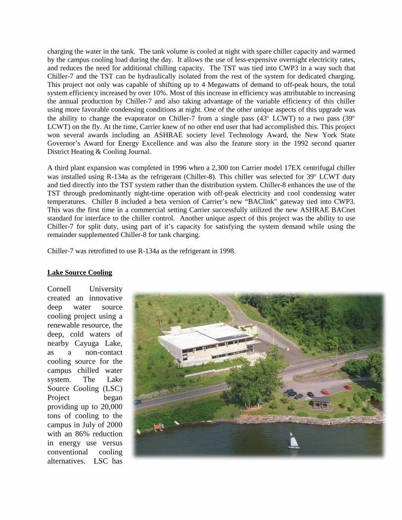
Lake Source Cooling
Cornell University created an innovative deep water source cooling project using a renewable resource, the deep, cold waters of nearby Cayuga Lake, as a non-contact cooling source for the campus chilled water system. The Lake Source Cooling (LSC) Project began providing up to 20,000 tons of cooling to the campus in July of 2000 with an 86% reduction in energy use versus conventional cooling alternatives. LSC has

been described as “a project that supports a sustainable future.” The LSC project is a replacement and upgrade of the central campus chilled water system with a more environmentally sound design. Cornell University operates a large system to provide central cooling to about forty percent (4 million square feet) of its core campus. In 1994, pressures on the existing highly efficient (variable speed chiller, variable speed pumping, chilled water thermal storage, winter “free” cooling, fully automated controls, and .75 kW/ton delivered annual efficiency) system, such as CFC phase-out, load growth, aging equipment and rising energy costs, necessitated a substantial change. LSC was chosen as the best available technology from the numerous options studied. Construction began in the spring of 1999, with start-up and commissioning occurring during the summer of 2000. Though it required more initial investment than replacing the system with standard refrigeration technology, LSC is providing the university with a method of cooling that eliminates CFC-containing refrigeration equipment and its associated energy use. LSC draws water through a 2mm wedge-wire screened intake about 10 feet above the lake bottom, at a water depth of 250 feet. At this depth, Cayuga Lake remains cold (about 39°F) year-round. The cold water is piped to a shoreline heat exchange facility, where it transfers its coldness through solid stainless-steel plates to water that circulates to the campus in a second loop of pipeline. The two water flows can never mix. Water drawn from deep in the lake is returned through a diffuser located about 500 feet offshore, at a water depth of 10 ft. The only change in the Cayuga Lake water is addition of heat; all the heat added to the lake is released each winter. The chilled campus water is pumped up to the campus to cool equipment and buildings via a closed-loop system, and because heat flows naturally from hot to cold, no extra energy is required beyond that needed to move the water through the pipes.
The Lake Source Cooling Process
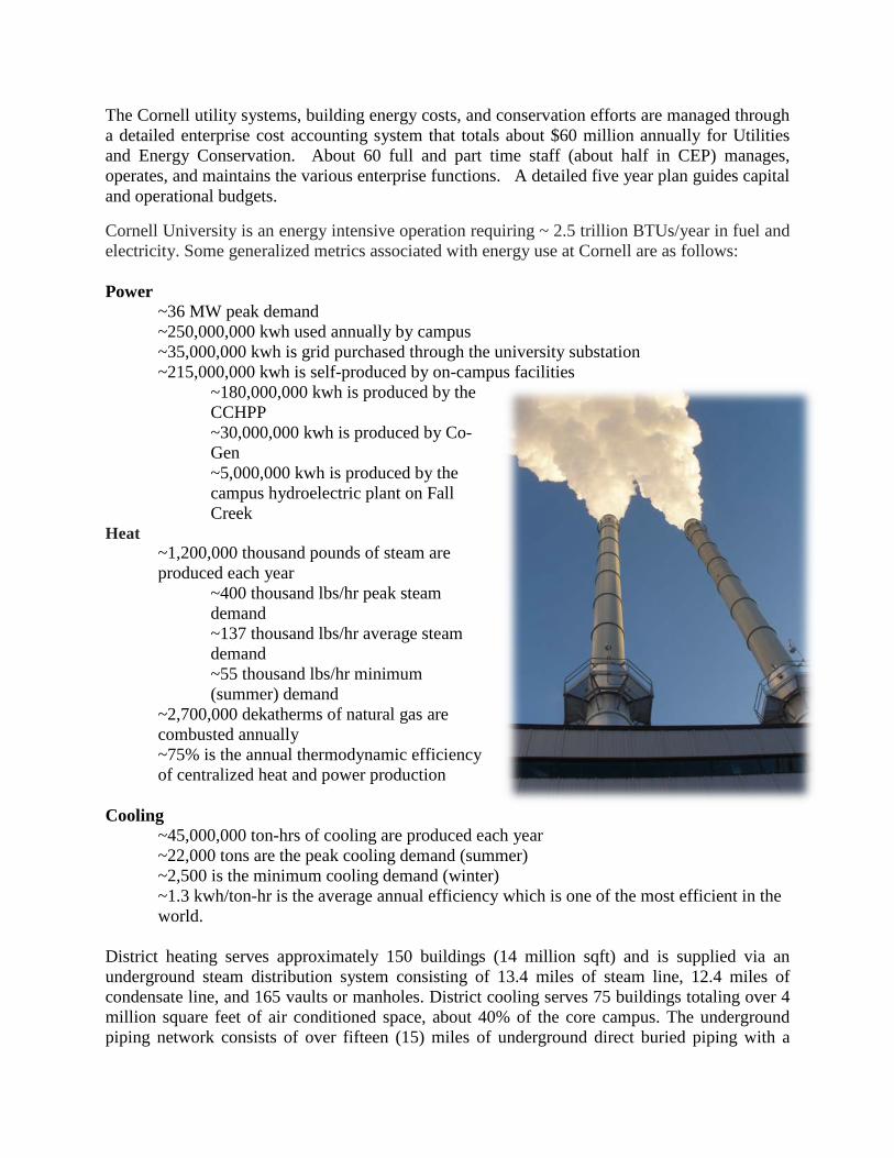
Average LSC Performance
0
1,000,000
2,000,000
3,000,000
4,000,000
5,000,000
6,000,000
January
Febru
aryMarc
hApril
MayJu
neJu
ly
August
Septem
ber
October
November
Decem
ber
Month
Ener
gy (K
wh)
Kwh Saved
Kwh Used
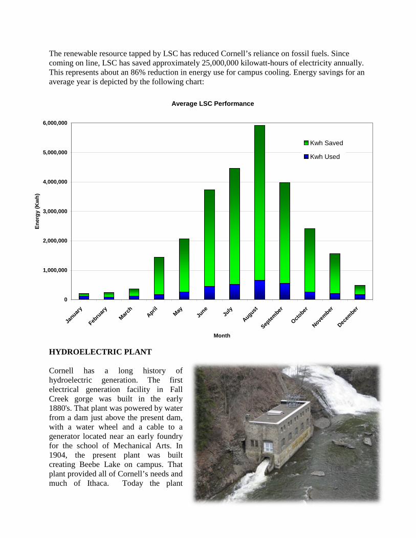
The renewable resource tapped by LSC has reduced Cornell’s reliance on fossil fuels. Since coming on line, LSC has saved approximately 25,000,000 kilowatt-hours of electricity annually. This represents about an 86% reduction in energy use for campus cooling. Energy savings for an average year is depicted by the following chart:
HYDROELECTRIC PLANT
Cornell has a long history of hydroelectric generation. The first electrical generation facility in Fall Creek gorge was built in the early 1880's. That plant was powered by water from a dam just above the present dam, with a water wheel and a cable to a generator located near an early foundry for the school of Mechanical Arts. In 1904, the present plant was built creating Beebe Lake on campus. That plant provided all of Cornell’s needs and much of Ithaca. Today the plant

provides 2% of campus needs. Water is supplied to the plant from Beebe Lake by a five-foot diameter underground penstock which is 1700 feet long. The existing intake dates to 1953 and was upgraded in 1981.
The original plant capacity was 300 kW with 2 Pelton Wheel turbines and 2 30kW DC exciters. This was increased in 1913 by adding a 360 kW Francis turbine. The facility was overhauled in 1935 after being completely flooded. In 1957, No. 2 generator was replaced with a 175 kW unit. The plant capacity then stood at 850 kW @2,400 volts. In this configuration, the plant last operated in 1970. It was vandalized in 1972.
In 1981, the plant was completely renovated and all the original machinery removed except for one of the DC exciters. Two Ossberger crossflow turbines were installed with a total rated capacity of 1,870 kW. The plant, however, is limited to about 1,100 kW output because of the size of the penstock and intake works. This hydroelectric plant is "run of river", which means that no water is stored. At all times, 10 cfs must continue to pass over the dam. On an annual basis, this plant produces approximately 5,000,000 kwh of electricity representing 2% of total campus usage. In early 2008 a digital automation project was installed that significantly improves operations and reliability, and is expected to increase output by about 20% or 1 million kWhr/yr.