
Coriolis Mass Flowmeter Proline Promass 80info.smithmeter.com/literature/docs/mn0m029.pdf ·...
44
The Most Trusted Name In Measurement Coriolis Mass Flowmeter Proline Promass 80 Description of Device Functions Issue/Rev. 0.0 (5/09) Bulletin MN0M029 0000 0001 0002 0003 0004 0005 000 AAA A 1000 1001 1002 1003 1004 1005 100 BAA B 2000 2001 2002 2003 2004 2005 200 CAA C 3000 3001 3002 3003 3004 3005 300 DAA D 4000 4001 4002 4003 4004 4005 400 EAA E 5000 5001 5002 5003 5004 500 FAA F 4200 5200 4201 5201 4202 5202 4203 5203 4204 4205 420 520 2400 2401 2402 2403 2404 2405 240 CCA 2200 2201 2202 2203 2204 2205 220 CBA 0200 0201 0202 0203 0204 0205 020 0000 0001 0002 0003 0004 0005 000 AAA A 1000 1001 1002 1003 1004 1005 100 BAA B 2000 2001 2002 2003 2004 2005 200 CAA C 3000 3001 3002 3003 3004 3005 300 DAA D 4000 4001 4002 4003 4004 4005 400 EAA E 5000 5001 5002 5003 5004 500 FAA F 4200 5200 4201 5201 4202 5202 4203 5203 4204 4205 420 520 2400 2401 2402 2403 2404 2405 240 CCA 2200 2201 2202 2203 2204 2205 220 CBA 0200 0201 0202 0203 0204 0205 020 1000 1001 10 100 BAA B 2000 2001 20 200 CAA C 3000 3001 30 300 DAA D 4000 4001 40 400 EAA E 5000 5001 50 500 FAA F 4200 5200 4201 5201 4 5 420 520 2400 2401 24 240 CCA 2200 2201 2 220 CBA 0200 0201 0 020 Valid as of version V 3.05.XX (device software)
Transcript of Coriolis Mass Flowmeter Proline Promass 80info.smithmeter.com/literature/docs/mn0m029.pdf ·...

The Most Trusted Name In Measurement
Coriolis Mass Flowmeter
Proline Promass 80Description of Device Functions
Issue/Rev. 0.0 (5/09) Bulletin MN0M029
0000 0001 0002 0003 0004 0005000AAAA
1000 1001 1002 1003 1004 1005100BAAB
2000 2001 2002 2003 2004 2005200CAAC
3000 3001 3002 3003 3004 3005300DAAD
4000 4001 4002 4003 4004 4005400EAAE
5000 5001 5002 5003 5004500FAAF
4200
5200
4201
5201
4202
5202
4203
5203
4204 4205420
520
2400 2401 2402 2403 2404 2405240CCA
2200 2201 2202 2203 2204 2205220CBA
0200 0201 0202 0203 0204 0205020
1000 1001 10100BAAB
2000 2001 20200CAAC
3000 3001 30300DAAD
4000 4001 40400EAAE
5000 5001 50500FAAF
4200
5200
4201
5201
4
5
420
520
2400 2401 24240CCA
2200 2201 2220CBA
0200 0201 0020
Valid as of versionV 3.05.XX (device software)

Device Functions Proline Promass 80 PROFIBUS PA
2 Endress+Hauser

Device Functions Proline Promass 80 PROFIBUS PA Table of contents
3
Table of contents
Table of contents . . . . . . . . . . . . . . . . . . . . . 3
1 Function matrix . . . . . . . . . . . . . . . . . . 5
2 Group MEASURED VALUES . . . . . . . . 7
3 Group SYSTEM UNITS . . . . . . . . . . . . 8
4 Group QUICK SETUP . . . . . . . . . . . . 13
5 Group OPERATION . . . . . . . . . . . . . 16
6 Group USER INTERFACE . . . . . . . . . 18
7 Group TOTALIZER . . . . . . . . . . . . . . 21
8 Group COMMUNICATION . . . . . . . . 24
9 Group PROCESS PARAMETER . . . . . 27
10 Group SYSTEM PARAMETER . . . . . . 32
11 Group SENSOR DATA . . . . . . . . . . . . 33
12 Group SUPERVISION . . . . . . . . . . . . 35
13 Group SIMULATION SYSTEM . . . . . . 36
14 Group SENSOR VERSION . . . . . . . . . 37
15 Group AMPLIFIER VERSION . . . . . . 37
16 Factory settings . . . . . . . . . . . . . . . . . 38
Index . . . . . . . . . . . . . . . . . . . . . . . . . . . . . 41

Table of contents Device Functions Proline Promass 80 PROFIBUS PA
4

Device Functions Proline Promass 80 PROFIBUS PA 1 Function matrix
5
1 Function matrix
1.1 Layout and operation of the function matrix
The function matrix consists of two levels - the groups and the groups' functions. The groups are
the highest-level grouping of the operation options for the device. A number of functions are
assigned to every group. By selecting the group, you can access the functions in which the operation
or configuration of the device takes place.
An overview of all the groups available is provided in the Table of Contents on Page 3 and in the
graphic illustration of the function matrix on Page 6.
Page 6 also provides you with an overview of all the functions available with cross-references to the
exact function description. The individual functions are described as of Page 7.
Example for configuring a function (changing the display language from German to English):
➀ Enter the function matrix (N key).
➁ Select the OPERATION group.
➂ Select the LANGUAGE function, then change the option from DEUTSCH to ENGLISH P
and save N(the display text now appears in English).
➃ Exit the function matrix (ESC > 3 seconds).
A0001142
>3s
- + E
Esc
E
E
E
E
E E E E E
–
+
+
Esc
–+
Esc
–
+
Esc
–
Em
n
o
p

1 Function matrix Device Functions Proline Promass 80 PROFIBUS PA
6
1.2 Illustration of the function matrix
UN
IT L
EN
GT
H
(P.
11
)
BLO
CK
SE
LE
CT
ION
(P.
25
)
DE
NSIT
Y S
ET
PO
INT
(P.
29
)
DE
NSIT
Y C
OE
FF. C
1
(P.
34
)
UN
IT T
EM
P.
(P.
11
)
CY
CL.
CA
LC
. T
OT
.
(P.
23
)
CH
EC
K C
ON
FIG
.
(P.
25
)
ZE
RO
PT
. A
DJ.
(P.
29
)
DE
NSIT
Y C
OE
FF.
C 0
(P.
33
)
UN
IT R
EFE
RE
NC
E
DE
NSIT
Y (
P.
11
)
TE
ST D
ISPLA
Y
(P.2
0)
TO
TA
LIZ
ER
MO
DE
(P.2
2)
DE
VIC
E I
D
(P.2
5)
FIX
ED
RE
FE
RE
NC
E
DE
NSIT
Y (
P.
28
)
CA
L.
CO
EFF.
KD
2
(P.3
3)
MA
X.
CA
RR
. T
EM
P
(P.3
4)
UN
IT D
EN
SIT
Y
(P.
11)
BA
CK
LIG
HT
(P.
20)
PR
ESE
T T
OT
ALIZ
ER
(P.
22)
AC
T.
BA
UD
RA
TE
(P.
25)
EP
D R
ESP
. T
IME
(P.
28)
CA
L.
CO
EFF.
KD
1
(P.
33)
MIN
. C
AR
R.
TE
MP
(P.
34)
TE
MP
ER
AT
UR
E
(P.7
)
UN
IT S
TA
ND
AR
D
VO
LU
ME
(P
.1
0)
CO
NT
RA
ST
LC
D
(P.
19
)
SE
T T
OT
ALIZ
ER
(P.
22
)
PR
OFIL
E V
ER
SIO
N
(P.
25
)
EP
D V
ALU
E H
IGH
(P.
28
)
TE
MP
. C
OE
FF.
KT
(P.
33
)
MA
X.
FL.
TE
MP
(P.
34
)
ST
OR
AG
E
(P.
35
)
RE
FE
RE
NC
E D
EN
SIT
Y
(P.
7)
UN
IT C
OR
R.
VO
LU
ME
FL. (P
.1
0)
AC
CE
SS C
OD
E C
OU
NT
.
(P.
17
)
DIS
PLA
Y D
AM
PIN
G
(P.
19
)
UN
IT T
OT
AL.
(P.
21
)
SE
T U
NIT
TO
BU
S
(P.
24
)
EP
D V
ALU
E L
OW
(P.
28
)
PR
ESS
UR
E
(P.
31
)
FLO
W D
AM
P.
(P.
32
)
TE
MP
. C
OE
FF. K
M 2
(P.
33
)
MIN
. FL.
TE
MP
(P.
34
)
OPE
RA
TIO
N H
OU
RS
(P.
35
)
DE
NSIT
Y
(P.
7)
UN
IT V
OLU
ME
(P.
9)
ST
AT
US A
CC
ESS
(P.
17
)
FO
RM
AT
(P.
19
)
CH
AN
NE
L
(P.
21
)
SELE
CT
ION
GSD
(P.
24
)
EP
D
(P.
28
)
PR
ESS
UR
E M
OD
E
(P.
30
)
DE
NSIT
Y D
AM
PIN
G
(P.
32
)
TE
MP
. C
OE
FF. K
M
(P.
33
)
DE
NSIT
Y C
OE
FF.
C 5
(P.
34
)
SYST
EM
RE
SE
T
(P.
35
)
SW
RE
V.
I/O
MO
D.
(P.
37
)
CO
RR
EC
TE
D V
OLU
ME
FLO
W (
P.
7)
UN
IT V
OL. FLO
W (
P.
9)
DE
FIN
E P
RIV
AT
E C
OD
E
(P.
17
)
10
0%
VA
LU
E
(P.
19
)
OV
ER
FLO
W
(P.
21
)
WR
ITE
PR
OT
EC
TIO
N
(P.
24
)
CH
AN
NE
L
(P.
26
)
OFF V
ALU
E
(P.
27
)
RE
ST
OR
E O
RIG
. (P
.30)
PO
S.
ZE
RO
RE
TU
RN
(P.
32
)
NO
MIN
AL D
IAM
ET
ER
(P.
33
)
DE
NSI
TY
CO
EFF.
C 4
(P.
34
)
ALA
RM
DE
LA
Y (
P.
35
)
VA
LU
E S
IM.
ME
ASU
RA
ND
(P
.3
6)
SW
RE
V.
NO
. S-D
AT
(P.
37
)
I/O
MO
DU
LE
TY
PE
(P.
37
)
VO
LU
ME
FLO
W
(P.
7)
UN
IT M
ASS
(P.
8)
SE
TU
P C
OM
MU
NIC
A.
(P.
13
)
AC
CE
SS
CO
DE
(P.
17
)
ASS
IGN
LIN
E 2
(P.
18
)
TO
T.
OU
T V
ALU
E
(P.
21
)
BU
S A
DD
RE
SS
(P.
24
)
DIS
PLA
Y V
ALU
E
(P.
26
)
ON
VA
LU
E
(P.
27
)
DE
NSIT
Y A
DJU
ST
ME
NT
(P.
30
)
ME
ASU
RIN
G M
OD
E
(P.
32
)
ZE
RO
PO
INT
(P.
33
)
DE
NSIT
Y C
OE
FF. C
3
(P.
34
)
PR
EV
. S
YS.
CO
ND
ITIO
N
SIM
. M
EA
SUR
AN
D
(P.
36
)
SE
NSO
R T
YPE
(P.
37
)
LA
NG
UA
GE
GR
OU
P
(P.
37
)
MA
SS F
LO
W
(P.
7)
UN
IT M
ASS
FLO
W
(P.
8)
UN
IT P
RE
SSU
RE
(P.1
2)
SE
TU
P C
OM
MIS
S
(P.1
3)
LA
NG
UA
GE
(P.1
6)
ASS
IGN
LIN
E 1
(P.1
8)
SE
L.
TO
TA
L.
(P.2
1)
TA
G N
AM
E
(P.2
4)
OU
T V
ALU
E
(P.2
5)
ASSIG
N L
F C
UT
OFF
(P.2
7)
ME
AS.
FLU
ID
(P.2
9)
INST
ALLA
TIO
N
DIR
EC
TIO
N
K-F
AC
TO
R
(P.3
3)
DE
NSIT
Y C
OE
FF.
C 2
(P.3
4)
AC
T. S
YS. C
ON
DIT
ION
(P.3
5)
SIM
. FA
ILSA
FE
MO
DE
(P.3
6)
SER
IAL N
UM
BE
R (
P.
37
)
SW
RE
V.
AM
P.
(P.3
7)
⇓ ⇓ ⇓ ⇓ ⇓ ⇓ ⇓ ⇓ ⇓ ⇓ ⇓ ⇓ ⇓ ⇓ ⇓M
EA
SU
RE
D V
ALU
ES
(P.
7)
SY
STE
M U
NIT
S
(P.
8)
QU
ICK
SE
TU
P
(P.
13
)
OPE
RA
TIO
N
(P.
16
)
USE
R I
NT
ER
FA
CE
(P.
18
)
TO
TA
LIZ
ER
(P.
21
)
CO
MM
UN
ICA
TIO
N
(P.
24
)
PR
OC
ESS P
AR
AM
.
(P.
27
)
SY
ST
EM
PA
RA
M.
(P.
32
)
SE
NSO
R D
AT
A
(P.
33
)
SUP
ER
VIS
ION
(P
.35
)
SIM
ULA
T. SY
STE
M
(P.
36
)
SE
NSO
R V
ER
SIO
N
(P.
37
)
AM
PLIF
IER
VE
RS.
(P.
37
)

Device Functions Proline Promass 80 PROFIBUS PA 2 Group MEASURED VALUES
7
2 Group MEASURED VALUES
Function description MEASURED VALUES
! Note!
• The engineering unit of the measured variable displayed here can be set in the “SYSTEM UNITS” group.
• If the fluid in the pipe flows backwards, a negative sign prefixes the flow reading on the display.
MASS FLOW The currently measured mass flow appears on the display.
Display:
5-digit floating-point number, including unit and sign
(e.g. 462.87 kg/h; –731.63 lb/min; etc.)
VOLUME FLOW The calculated volume flow appears on the display. The volume flow is derived from the
measured mass flow and the measured density of the fluid.
Display:
5-digit floating-point number, including unit and sign
(e.g. 5.5445 dm³/min; 1.4359 m³/h; –731.63 gal/d; etc.)
CORRECTED VOLUME
FLOW
The calculated corrected volume flow appears on the display. The corrected volume flow
is derived from the measured mass flow and the reference density (density at reference
temperature, measured or fixed entry).
Display:
5-digit floating-point number, including unit and sign
(e.g. 1.3549 Nm³/h; 7.9846 scm/day; etc.)
DENSITY The currently measured density or its specific gravity appears on the display.
Display:
5-digit floating-point number, including unit, corresponding to 0.1000 to 6.0000 kg/dm³
(e.g. 1.2345 kg/dm³; 993.5 kg/m³; 1.0015 SG_20 °C; etc.)
REFERENCE DENSITY The density of the fluid at reference temperature appears on the display. The reference
density can either be measured or specified via the FIXED REFERENCE DENSITY
function (see Page 28).
Display:
5-digit floating point number, incl. unit, corresponding to 0.1000 to 6.0000 kg/dm³
(e.g. 1.2345 kg/dm³; 993.5 kg/m³; 1.0015 SG_20 °C; etc.)
TEMPERATURE The currently measured temperature appears on the display.
Display:
max. 4-digit fixed-point number, including unit and sign
(e.g. –23.4 °C; 160.0 °F; 295.4 K; etc.)

3 Group SYSTEM UNITS Device Functions Proline Promass 80 PROFIBUS PA
8
3 Group SYSTEM UNITS
Function description SYSTEM UNITS
You can select the unit for the measured variable in this function group.
UNIT MASS FLOW For selecting the unit for displaying the mass flow (mass/time).
The unit you select here is also valid for:
• Low flow
Options:
Metric:
Gram → g/s; g/min; g/h; g/day
Kilogram → kg/s; kg/min; kg/h; kg/day
Metric ton → t/s; t/min; t/h; t/day
US:
Ounce → oz/s; oz/min; oz/h; oz/day
Pound → lb/s; lb/min; lb/h; lb/day
Ton → ton/s; ton/min; ton/h; ton/day
Factory setting:
Depends on country (kg/h or USlb/min)
UNIT MASS For selecting the unit for displaying the mass.
Options:
Metric → g; kg; t
US → oz; lb; ton
Factory setting:
Depends on country (kg or US lb)
! Note!
The unit of the totalizers is independent of your choice here. The unit for each totalizer is
selected separately for the totalizer in question.

Device Functions Proline Promass 80 PROFIBUS PA 3 Group SYSTEM UNITS
9
UNIT VOLUME FLOW For selecting the unit for displaying the volume flow (volume/time).
The unit you select here is also valid for:
• Low flow
Options:
Metric:
cubic centimeter → cm³/s; cm³/min; cm³/h; cm³/day
cubic decimeter → dm³/s; dm³/min; dm³/h; dm³/day
cubic meter → m³/s; m³/min; m³/h; m³/day
Milliliter → ml/s; ml/min; ml/h; ml/day
Liter → l/s; l/min; l/h; l/day
Hectoliter → hl/s; hl/min; hl/h; hl/day
Megaliter → Ml/s; Ml/min; Ml/h; Ml/day
US:
Cubic centimeter → cc/s; cc/min; cc/h; cc/day
Acre foot → af/s; af/min; af/h; af/day
cubic foot → ft³/s; ft³/min; ft³/h; ft³/day
Fluid ounce → oz f/s; oz f/min; oz f/h; oz f/day
Gallon → gal/s; gal/min; gal/h; gal/day
Kilogallon → Kgal/s; Kgal/min; Kgal/h; Kgal/day
Million gallon → Mgal/s; Mgal/min; Mgal/h; Mgal/day
Barrel (normal fluids: 31.5 gal/bbl) → bbl/s; bbl/min; bbl/h; bbl/day
Barrel (beer: 31.0 gal/bbl) → bbl/s; bbl/min; bbl/h; bbl/day
Barrel (petrochemicals: 42.0 gal/bbl) → bbl/s; bbl/min; bbl/h; bbl/day
Barrel (filling tanks: 55.0 gal/bbl) → bbl/s; bbl/min; bbl/h; bbl/day
Imperial:
Gallon → gal/s; gal/min; gal/h; gal/day
Mega gallon → Mgal/s; Mgal/min; Mgal/h; Mgal/day
Barrel (beer: 36.0 gal/bbl) → bbl/s; bbl/min; bbl/h; bbl/day
Barrel (petrochemicals: 34.97 gal/bbl) → bbl/s; bbl/min; bbl/h; bbl/day
Factory setting:
Depends on country (m³/h or US Mgal/day)
UNIT VOLUME For selecting the unit for displaying the volume.
Options:
Metric → cm³; dm³; m³; ml; l; hl; Ml Mega
US → cc; af; ft³; oz f; gal; Kgal; Mgal; bbl (normal fluids); bbl (beer);
bbl (petrochemicals); bbl (filling tanks)
Imperial → gal; Mgal; bbl (beer); bbl (petrochemicals)
Factory setting: m³
!Note!
The unit of the totalizers is independent of your choice here. The unit for each totalizer is
selected separately for the totalizer in question.
Function description SYSTEM UNITS

3 Group SYSTEM UNITS Device Functions Proline Promass 80 PROFIBUS PA
10
UNIT CORRECTED
VOLUME FLOW
For selecting the unit for displaying the corrected volume flow (corrected volume/time).
The unit you select here is also valid for:
• Low flow
Options:
Metric:
Nl/s
Nl/min
Nl/h
Nl/day
Nm³/s
Nm³/min
Nm³/h
Nm³/day
US:
Sm³/s
Sm³/min
Sm³/h
Sm³/day
Scf/s
Scf/min
Scf/h
Scf/day
Factory setting:
Nm³/h
UNIT CORRECTED
VOLUME
For selecting the unit for displaying the corrected volume.
Options:
Metric:
Nm³
Nl
US:
Sm³
Scf
Factory setting:
Nm³
!Note!
The unit of the totalizers is independent of your choice here. The unit for each totalizer is
selected separately for the totalizer in question.
Function description SYSTEM UNITS

Device Functions Proline Promass 80 PROFIBUS PA 3 Group SYSTEM UNITS
11
UNIT DENSITY For selecting the unit for displaying the fluid density.
The unit you select here is also valid for:
• Density response value for EPD
• Density adjustment value
Options:
Metric → g/cm³; g/cc; kg/dm³; kg/l; kg/m³; SD 4 °C, SD 15 °C, SD 20 °C; SG 4 °C,
SG 15 °C, SG 20 °C
US → lb/ft³; lb/gal; lb/bbl (normal fluids); lb/bbl (beer);
lb/bbl (petrochemicals); lb/bbl (filling tanks)
Imperial → lb/gal; lb/bbl (beer); lb/bbl (petrochemicals)
Factory setting:
kg/l
SD = Specific Density, SG = Specific Gravity
The specific density is the ratio of fluid density to water density
(at water temperature = 4, 15, 20 °C)
UNIT REFERENCE
DENSITY
For selecting the unit for displaying the reference density.
The unit you select here is also valid for:
• Fixed reference density (for calculation of corrected volume flow)
Options:
Metric:
kg/Nm3
kg/Nl
US:
g/Scc
kg/Sm3
lb/Scf
Factory setting:
kg/Nl
UNIT TEMPERATURE For selecting the unit for displaying the temperature.
The unit you select here is also valid for:
• Reference temperature (for corrected vol. measurement with measured reference
density)
Options:
°C (Celsius)
K (Kelvin)
°F (Fahrenheit)
R (Rankine)
Factory setting:
°C (Celsius)
UNIT LENGTH For selecting the unit for displaying the length of the nominal diameter.
The unit you select here is also valid for:
• Nominal diameter of sensor (NOMINAL DIAMETER function on Page 33)
Options:
MILLIMETER
INCH
Factory setting:
Depends on country (MILLIMETER or INCH)
Function description SYSTEM UNITS

3 Group SYSTEM UNITS Device Functions Proline Promass 80 PROFIBUS PA
12
UNIT PRESSURE For selecting the unit for displaying the pressure.
The unit you select here is also valid for:
• Specified pressure (PRESSURE function on Page 31)
Options:
bara
barg
psia
psig
Factory setting: barg
Function description SYSTEM UNITS

Device Functions Proline Promass 80 PROFIBUS PA 4 Group QUICK SETUP
13
4 Group QUICK SETUP
QUICK SETUP function description
! Note!
• The Quick Setups are only available by means of the local display.
• Flowcharts of the various Quick Setups can be found on the following pages.
• More information on the setups can be found in Operating Instructions BA072D.
QUICK SETUP
COMMISSIONING
For starting the Setup menu.
Options:
YES
NO
Factory setting:
NO
QUICK SETUP
COMMUNICATION
For starting the Setup menu.
Options:
YES
NO
Factory setting:
NO

4 Group QUICK SETUP Device Functions Proline Promass 80 PROFIBUS PA
14
4.1 Quick Setup “Commissioning”
Note!
The display returns to the QUICK SETUP COMMISSIONING cell if you press the Q key
combination during parameter interrogation.
A0004749-en
Fig. 1: Quick Setup Commissioning.
➀ The “DELIVERY SETTINGS” option sets every selected unit to the factory setting.
The “ACTUAL SETTINGS” option accepts the units you set beforehand.
➁ Only units not yet configured in the current Setup are offered for selection in each cycle. The unit for mass,
volume and corrected volume is derived from the corresponding flow unit.
o The “YES” option remains visible until all the units have been configured.
“NO” is the only option displayed when no further units are available.
p The “automatic parameterization of the display” option contains the following basic settings/factory settings:
YES: line 1= mass flow; line 2 = totalizer 1
NO: The existing (selected) settings remain.
++ +E E
HOME-POSITION
Esc
E+-
XXX.XXX.XX
Yes
Yes
No
No
Mass flow Volume flow Density
Selection System Units
Configuration another unit ?
Automatically configuration display ?
Temperature Quit
UnitMass flow
UnitflowVolume
UnitDensity
UnitTemperature
UnitTotalizer
UnitTotalizer
Automaticallyparameterization
of the display
Language
Pre-setting
Quick SetupQuick SetupCommission
n
o
Corr. Vol. flow
UnitCorr. Vol. flow
UnitRef. Density
FixRef. Density
p
Selection pre-settings
Actual SettingsDeliver Settingsy
m
Set Unit to Bus
SET UNITSOFF
m

Device Functions Proline Promass 80 PROFIBUS PA 4 Group QUICK SETUP
15
4.2 Quick Setup “Communication”
To establish cyclic data transfer, various arrangements between the PROFIBUS master and the slave
are required which have to be taken into consideration when configuring various functions. These
functions can be configured quickly and easily by means of the "Communication" Quick Setup.
A0002600-EN
Fig. 2: Quick Setup Communication.
++E
+E
BQuick SetupQuick Setup
6101
6140
6141
1006
Esc
E+-
XXX.XXX.XX
HOME-POSITION
Fieldbus Address
SelectionGSD
Unit To Bus
SetupCommunication
5 Group OPERATION Device Functions Proline Promass 80 PROFIBUS PA
16
5 Group OPERATION
Function description OPERATION
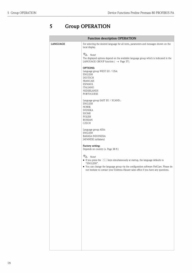
LANGUAGE For selecting the desired language for all texts, parameters and messages shown on the
local display.
! Note!
The displayed options depend on the available language group which is indicated in the
LANGUAGE GROUP function ( → Page 37).
OPTIONS:
Language group WEST EU / USA:
ENGLISH
DEUTSCH
FRANCAIS
ESPANOL
ITALIANO
NEDERLANDS
PORTUGUESE
Language group EAST EU / SCAND.:
ENGLISH
NORSK
SVENSKA
SUOMI
POLISH
RUSSIAN
CZECH
Language group ASIA:
ENGLISH
BAHASA INDONESIA
JAPANESE (syllabary)
Factory setting:
Depends on country (s. Page 38 ff.)
! Note!
• If you press the OS keys simultaneously at startup, the language defaults to
“ENGLISH”.
• You can change the language group via the configuration software FielCare. Please do
not hesitate to contact your Endress+Hauser sales office if you have any questions.

Device Functions Proline Promass 80 PROFIBUS PA 5 Group OPERATION
17
ACCESS CODE! Note!
This function is only relevant for local operation and accessing via an operating program
(e.g. FieldCare) and does not affect cyclic data transmission via the PROFIBUS master
(Class 1).
All data of the measuring system are protected against inadvertent change. Programming
is disabled and the settings cannot be changed until a code is entered in this function. If
you press the OS operating elements in any function, the measuring system
automatically goes to this function and the prompt to enter the code appears on the
display (when programming is disabled).
You can enable programming by entering your personal code (
factory setting = 80, see DEFINE PRIVATE CODE function on Page 17).
User input:
max. 4-digit number: 0 to 9999
! Note!
• Programming is disabled if you do not press a key within 60 seconds following
automatic return to the HOME position.
• You can also disable programming in this function by entering any number (other than
the defined private code).
• The Endress+Hauser service organization can be of assistance if you mislay your
personal code.
DEFINE PRIVATE CODE For specifying a personal code to enable programming.
User input:
0 to 9999 (max. 4-digit number)
Factory setting:
80
! Note!
• Programming is always enabled with the code “0”.
• Programming has to be enabled before this code can be changed. When programming
is disabled this function is not available, thus preventing others from accessing your
personal code.
STATUS ACCESS Use this function to display the status of access to the function matrix.
Display:
ACCESS CUSTOMER (parameterization possible)
LOCKED (parameterization disabled)
ACCESS CODE
COUNTER
Displays how often the customer code, service code or the digit “0” (code-free) has been
entered to gain access to the measuring device.
Display:
max. 7-digit number: 0 to 9999999
Factory setting:
0
Function description OPERATION

6 Group USER INTERFACE Device Functions Proline Promass 80 PROFIBUS PA
18
6 Group USER INTERFACE
Function description USER INTERFACE
ASSIGN LINE 1 For selecting the display value for the main line (top line of the local display).
Options:
OFF
MASS FLOW
MASS FLOW IN %
VOLUME FLOW
VOLUME FLOW IN %
DENSITY
TEMPERATURE
TOTALIZER 1
CORRECTED VOLUME FLOW
CORRECTED VOLUME FLOW IN %
REFERENCE DENSITY TEMPERATURE
AI1 - OUT VALUE
AI2 - OUT VALUE
AI3 - OUT VALUE
AI4 - OUT VALUE
AO - DISP. VALUE
TOT1 - OUT VALUE
Factory setting:
MASS FLOW
ASSIGN LINE 2 For selecting the display value for the additional line (bottom line of the local display).
Options:
OFF
MASS FLOW
MASS FLOW IN %
VOLUME FLOW
VOLUME FLOW IN %
DENSITY
TEMPERATURE
TOTALIZER 1
TAG NAME
OPERATING/SYSTEM CONDITIONS
FLOW DIRECTION READING
MASS FLOW BARGRAPH IN %
VOLUME FLOW BARGRAPH IN %
CORRECTED VOLUME FLOW
CORRECTED VOLUME FLOW IN %
CORRECTED VOLUME FLOW BARGRAPH IN %
REFERENCE DENSITY
AI1 - OUT VALUE
AI2 - OUT VALUE
AI3 - OUT VALUE
AI4 - OUT VALUE
AO - DISP. VALUE
TOT1 - OUT VALUE
Factory setting:
TOT1 - OUT VALUE (totalizer)
Device Functions Proline Promass 80 PROFIBUS PA 6 Group USER INTERFACE
19
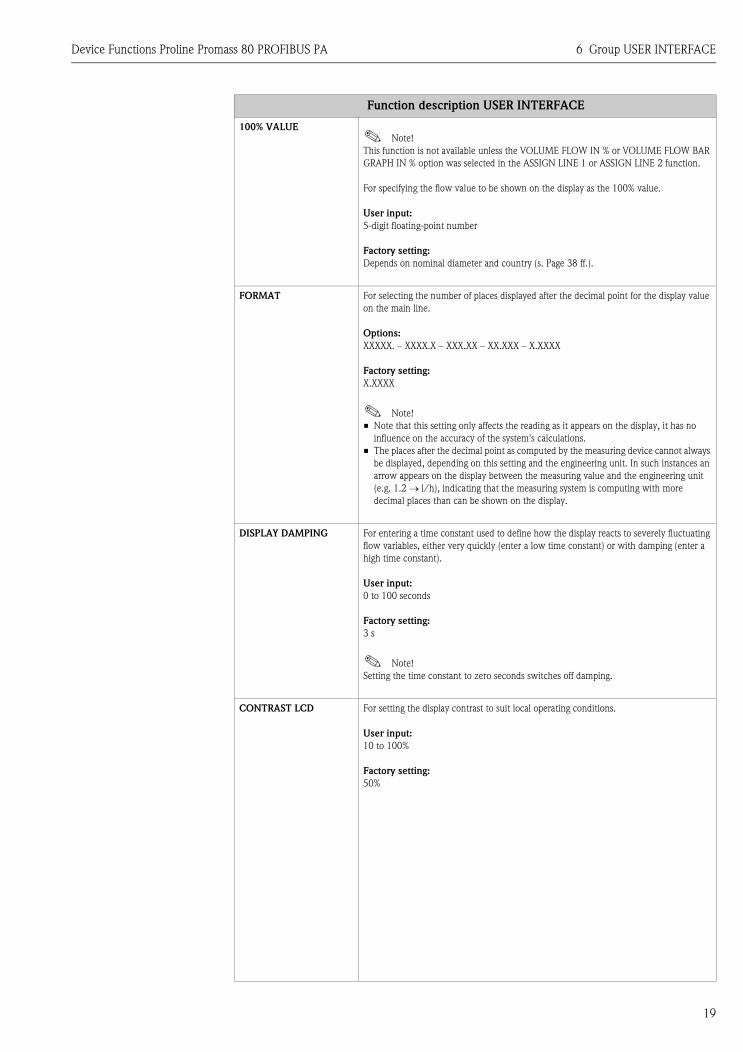
100% VALUE! Note!
This function is not available unless the VOLUME FLOW IN % or VOLUME FLOW BAR
GRAPH IN % option was selected in the ASSIGN LINE 1 or ASSIGN LINE 2 function.
For specifying the flow value to be shown on the display as the 100% value.
User input:
5-digit floating-point number
Factory setting:
Depends on nominal diameter and country (s. Page 38 ff.).
FORMAT For selecting the number of places displayed after the decimal point for the display value
on the main line.
Options:
XXXXX. – XXXX.X – XXX.XX – XX.XXX – X.XXXX
Factory setting:
X.XXXX
! Note!
• Note that this setting only affects the reading as it appears on the display, it has no
influence on the accuracy of the system's calculations.
• The places after the decimal point as computed by the measuring device cannot always
be displayed, depending on this setting and the engineering unit. In such instances an
arrow appears on the display between the measuring value and the engineering unit
(e.g. 1.2 → l/h), indicating that the measuring system is computing with more
decimal places than can be shown on the display.
DISPLAY DAMPING For entering a time constant used to define how the display reacts to severely fluctuating
flow variables, either very quickly (enter a low time constant) or with damping (enter a
high time constant).
User input:
0 to 100 seconds
Factory setting:
3 s
! Note!
Setting the time constant to zero seconds switches off damping.
CONTRAST LCD For setting the display contrast to suit local operating conditions.
User input:
10 to 100%
Factory setting:
50%
Function description USER INTERFACE
6 Group USER INTERFACE Device Functions Proline Promass 80 PROFIBUS PA
20
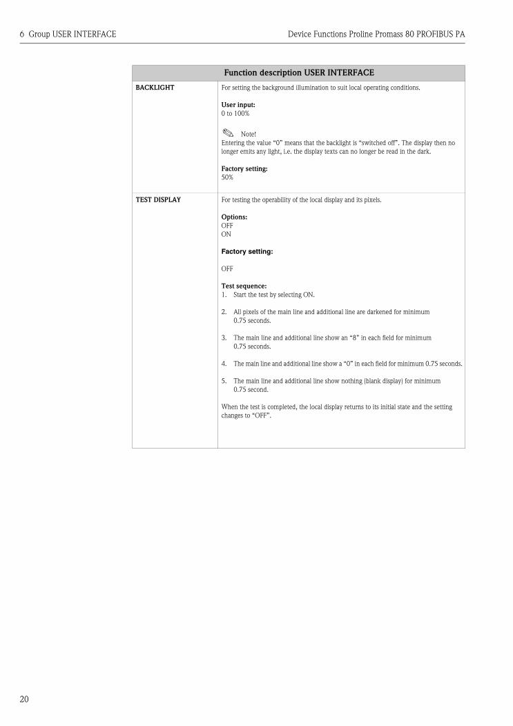
BACKLIGHT For setting the background illumination to suit local operating conditions.
User input:
0 to 100%
! Note!
Entering the value “0” means that the backlight is “switched off”. The display then no
longer emits any light, i.e. the display texts can no longer be read in the dark.
Factory setting:
50%
TEST DISPLAY For testing the operability of the local display and its pixels.
Options:
OFF
ON
Factory setting:
OFF
Test sequence:
1. Start the test by selecting ON.
2. All pixels of the main line and additional line are darkened for minimum
0.75 seconds.
3. The main line and additional line show an “8” in each field for minimum
0.75 seconds.
4. The main line and additional line show a “0” in each field for minimum 0.75 seconds.
5. The main line and additional line show nothing (blank display) for minimum
0.75 second.
When the test is completed, the local display returns to its initial state and the setting
changes to “OFF”.
Function description USER INTERFACE

Device Functions Proline Promass 80 PROFIBUS PA 7 Group TOTALIZER
21
7 Group TOTALIZER
Function description TOTALIZER
SELECT TOTALIZER For selecting the totalizer.
! Note!
The measuring device only has one totalizer.
Options:
TOTALIZER 1
Factory setting:
TOTALIZER 1
TOTALIZER OUT VALUE 1 The current totalizer value, including the unit, appears on the display.
Display:
Floating-point number, incl. unit and sign
OVERFLOW The total for the totalizer's overflow aggregated since measuring commenced appears
on the display.
Total flow quantity is represented by a floating-point number consisting of
max. 6 digits. You can use this function to view higher numerical values as overflows
(>999999). The effective quantity is thus the total of the OVERFLOW function plus the
value returned by the TOTALIZER OUT VALUE 1 function.
Example:
Reading after 2 overflows: 2 E7 (= 2000000).
The value displayed in the "TOTALIZER OUT VALUE 1" function = 96845.7 dm3
Effective total quantity = 2096845.7 dm3
Display:
integer with exponent, including sign, e.g. 2 E7
CHANNEL Assignment of the measured variable (volume flow) to the totalizer.
Options:
OFF
MASS FLOW
VOLUME FLOW
Factory setting:
MASS FLOW
! Note!
The totalizer is reset to “0” as soon as the selection is changed.
UNIT TOTALIZER For selecting the unit of the totalizer.
Options:
Metric → cm3; dm3; m3; ml; l; hl; Ml Mega
US → cc; af; ft3; oz f; gal; Kgal; Mgal; bbl (normal fluids); bbl (beer);
bbl (petrochemicals); bbl (filling tanks)
Imperial → gal; Mgal; bbl (beer); bbl (petrochemicals)
Factory setting:
m3

7 Group TOTALIZER Device Functions Proline Promass 80 PROFIBUS PA
22
SET TOTALIZER Control of the totalizer.
Options:
TOTALIZE
Totalizes the measured variable selected in the CHANNEL function.
RESET
Reset the totalizer to 0.
PRESET
The totalizer is set to the value defined in the PRESET TOTALIZER function.
! Note!
Note that selecting RESET or PRESET resets the totalizer to 0 or sets it to the preset
value respectively, but does not stop the totalizer.
This means that it immediately recommences totaling from the new setting. To stop the
totalizer, the HOLD VALUE option has to be selected in the TOTALIZER MODE
function.
Factory setting:
TOTALIZE
PRESET TOTALIZER For specifying a (start) value.
! Note!
This value is not accepted by the totalizer unless the PRESET option is selected in the
SET TOTALIZER function.
User input:
–99999 to 99999
Factory setting:
0
TOTALIZER MODE For selecting the operating mode of the totalizer.
Options:
BALANCE
Positive and negative flow components. The positive and negative flow components are
balanced. In other words, net flow in the flow direction is registered.
POSITIVE (forward)
Positive flow components only.
NEGATIVE (reverse)
Negative flow components only
HOLD VALUE
The totalizer stays at the last value. No further flow components are totaled.
Factory setting:
BALANCE
! Note!
For the calculation of the positive and negative flow components (BALANCE) or the
negative flow components only (NEGATIVE) to be carried out correctly, the
BIDIRECTIONAL option must be selected in the MEASURING MODE function
( → Page 32).
Function description TOTALIZER

Device Functions Proline Promass 80 PROFIBUS PA 7 Group TOTALIZER
23
CYCL. CALC. TOT. Use this function to define whether the totalizers 1 are updated on the local display
and in the operating program (e.g. FieldCare).
Options:
ON
Totalizers are always updated
OFF
Totalizers are only updated if the corresponding totalizer function block (TOTAL
module or function) has been configured for cyclic data transmission.
Factory setting:
ON
!Note!
Especially when conducting time-critical applications, optimization can be carried out
for unnecessary totalizer function blocks. For this purpose, OFF must be selected in this
function. When doing this, ensure that the totalizer is no longer updated on the local
display and in the operating program (e.g. FieldCare) when selecting OFF.
Function description TOTALIZER

8 Group COMMUNICATION Device Functions Proline Promass 80 PROFIBUS PA
24
8 Group COMMUNICATION
Function description COMMUNICATION
TAG NAME Use this function to assign a tag name to the measuring device. You can edit and read this
tag name at the local display or by means of an operating program (e.g. FieldCare).
User input: max. 16-character text, permissible: A-Z, 0-9, +,-,
punctuation marks
Factory setting: “_ _ _ _ _ _ _ _ _ _ _ _ _ _ _ _” (without text)
BUS ADDRESS For entering the device address.
User input: 0 to 126
Factory setting: 126
WRITE PROTECTION Indicates whether it is possible to write-access the device via PROFIBUS (acyclic data
transmission, e.g. via "FieldCare" operating program).
Display:
OFF → Write access via PROFIBUS (acyclic data transmission) possible
ON → Write access via PROFIBUS (acyclic data transmission) disabled
Factory setting:OFF
! Note!
Write protection is activated and deactivated by means of a jumper on the I/O module
(see Operating Instructions BA063D).
SELECTION GSD! Note!
During the configuration phase, every PROFIBUS device must verify an ID number
assigned by the PNO. Along with this device-specific ID number there are also PROFILE
ID numbers that also have to be accepted in the configuration phase for the purposes of
interchangeability between devices of different make. In this case the device might,
under certain circumstances, reduce the functionality for cyclic data to a profile-defined
scope.
Use this function to select the configuration behavior of the measuring device.
Options:
MANUFACT.SPEC
PROFILE GSD
Factory setting:
MANUFACT.SPEC
SET UNIT TO BUS Use this function to enable the transmission of the set system units to the automation
system. The set system units are transmitted to the automation system by pressing the
N key.
Options:
SET UNITS (transmission is started by pressing the N key)
! Note!
When transmitting, the scaling of the OUT value in the Analog Input Block is
automatically scaled to the set system unit and the OUT unit (output unit) is displayed in
the OUT_UNIT parameter. The preset system units are listed in the Operating
Instructions Proline Promass 80 PROFIBUS PA, BA 072D/06/en.
" Caution!
Activating this function can cause the output value OUT to change suddenly; this, in
turn, can affect subsequent control routines.

Device Functions Proline Promass 80 PROFIBUS PA 8 Group COMMUNICATION
25
PROFILE VERSION Use this function to display the profile version.
Display:
3.0
ACTUAL BAUDRATE Use this function to display the data transmission rate, set in the automation system, at
which the device communicates.
DEVICE ID Use this function to display the manufacturer-specific device ID.
Display:
0x1528 (= 1528 Hex)
! Note!
If the PROFILE GSD option was selected in the SELECTION GSD function, (see
Page 24), the PROFILE ID = 0x9742 (= 9742 Hex) is displayed in this function.
CHECK
CONFIGURATION
Use this function to see whether the configuration for cyclic data exchange of a Class 1
master has been accepted in Promass 80.
Display:
ACCEPTED (configuration accepted)
NOT ACCEPTED (configuration not accepted)
BLOCK SELECTION For selecting the PROFIBUS function block. If you select the Analog Input, the current
measured value is displayed in the OUT VALUE function. If you select the Analog
Output, the current measured value is displayed in the DISPLAY VALUE function.
Options:
ANALOG INPUT 1
ANALOG INPUT 2
ANALOG INPUT 3
ANALOG INPUT 4
ANALOG OUTPUT 1
Factory setting:
ANALOG INPUT 1
!Note!
If the PROFILE GSD option was selected in the SELECTION GSD function, the only
options that appear in this function are:
• ANALOG INPUT 1
• ANALOG INPUT 2
• ANALOG INPUT 3
OUT VALUE! Note!
This function is not available unless one of the following was selected in the BLOCK
SELECTION function:
• ANALOG INPUT 1
• ANALOG INPUT 2
• ANALOG INPUT 3
• ANALOG INPUT 4
This function shows the measured variable (AI module), incl. unit and status, cyclically
transmitted to the PROFIBUS master (Class 1).
Function description COMMUNICATION

8 Group COMMUNICATION Device Functions Proline Promass 80 PROFIBUS PA
26
DISPLAY VALUE!Note!
This function is not available unless ANALOG OUTPUT 1 was selected in the BLOCK
SELECTION function.
The measured variable (DISPLAY_VALUE module) cyclically transmitted from the
PROFIBUS master (Class 1) to the device appears on the display, including the unit and
status.
CHANNEL!Note!
This function is not available unless one of the following options was selected in the
BLOCK SELECTION function:
– ANALOG INPUT 1
– ANALOG INPUT 2
– ANALOG INPUT 3
– ANALOG INPUT 4
Use this function to assign a measured variable to the particular Analog Input function
block 1 to 4.
Options:
MASS FLOW
VOLUME FLOW
CORRECTED VOLUME FLOW
DENSITY
REFERENCE DENSITY
TEMPERATURE
Function description COMMUNICATION

Device Functions Proline Promass 80 PROFIBUS PA 9 Group PROCESS PARAMETER
27
9 Group PROCESS PARAMETER
Function description PROCESS PARAMETER
ASSIGN LOW FLOW CUT
OFF
Use this function to assign the switch point for low flow cutoff.
Options:
OFF
MASS FLOW
VOLUME FLOW
CORRECTED VOLUME FLOW
Factory setting:
MASS FLOW
ON-VALUE LOW FLOW
CUT OFF
Use this function to enter the switch-on point for low flow cutoff.
Low flow cutoff is active if the value entered is not equal to 0. The sign of the flow value
is highlighted on the display to indicate that low flow cutoff is active.
User input:
5-digit floating-point number
Factory setting:
0 [kg/h] or 0 [m3/h]
! Note!
The appropriate unit is taken from the SYSTEM UNITS function group (see Page 8).
OFF-VALUE LOW FLOW
CUT OFF
Use this function to enter the switch-off point for low flow cutoff.
Enter the switch-off point as a positive hysteresis from the switch-on point.
User input:
Integer 0 to 100%
Factory setting:
50%
Example:
A0001245
Q = Flow [volume/time]
t = Time
a = ON-VALUE LOW FLOW CUT OFF, e.g. 200 g/h
b = OFF-VALUE LOW FLOW CUT OFF, e.g. 10%
c = Low flow cutoff active
1 = Low flow cutoff is switched on, here e.g. at 200 g/h
2 = Low flow cutoff is switched off, here e.g. at 220 g/h
H = Hysteresis
1
c c
Q
t
1
2b
a
2
H

9 Group PROCESS PARAMETER Device Functions Proline Promass 80 PROFIBUS PA
28
EMPTY PIPE DETECTION
(EPD)
Use this function to activate the empty pipe detection (EPD). With empty measuring
tubes, the measured density of the fluid falls below the value specified in the EPD VALUE
LOW function.
Options:
OFF
ON
Factory setting:
Liquid: ON
Gas: OFF
" Caution!
• Select a correspondingly low value for the EPD VALUE LOW so that the difference to
the effective density of the fluid is sufficiently large. This ensures that totally empty
measuring tubes and not partially filled ones are detected.
• For gas measurement, we strongly recommend you switch off empty pipe detection
due to the low gas densities.
EPD VALUE LOW! Note!
This function is not available unless the ON option was selected in the EPD function.
Use this function to specify a lower threshold value (limit value) for the measured density
as problems can occur in the process if the density is too low.
User input:
5-digit floating-point number
Factory setting:
0.2000 g/cc
EPD VALUE HIGH! Note!
This function is not available unless the ON option was selected in the EPD function.
Use this function to specify an upper threshold value (limit value) for the measured
density.
User input:
5-digit floating-point number
Factory setting:
6.0000 g/cc
EPD RESPONSE TIME Use this function to enter the time span for which the criteria for an empty pipe have to
be satisfied without interruption before a notice message or fault message is generated.
User input:
fixed-point number: 1.0 to 60.0 s
Factory setting:
1.0 s
FIXED REFERENCE
DENSITY
Use this function to enter a fixed value for the reference density with which the corrected
volume flow or corrected volume is calculated.
User input:
5-digit floating-point number
Factory setting:
1 kg/Nl
Function description PROCESS PARAMETER

Device Functions Proline Promass 80 PROFIBUS PA 9 Group PROCESS PARAMETER
29
ZERO POINT
ADJUSTMENT
Use this function to automatically start zero point adjustment. The new zero point
determined by the measuring system is adopted by the ZERO POINT function (see
Page 33).
User input:
CANCEL - START
Factory setting:
CANCEL
" Caution!
Before carrying this out, please refer to the Operating Instructions Proline Promass 80
PROFIBUS PA, BA 072D/06/en for a detailed description of the procedure for zero point
adjustment.
! Note!
• Programming is disabled during zero point adjustment.
The message “ZERO ADJUST RUNNING” appears on the display.
• If the zero point adjustment is not possible (e.g. if v > 0.1 m/s) or has been canceled,
the alarm message “ZERO ADJUST NOT POSSIBLE” appears on the display.
• On completion of the zero point adjustment, the new zero point can be displayed with
the N key. If the N key is pressed a second time, you return to the ZERO POINT
ADJUSTMENT function.
DENSITY SETPOINT Use this function to enter the density setpoint value of the fluid for which you want to
carry out field density adjustment.
User input:
5-digit floating point number, incl. unit, (corresponds to 0.1 to 5.9999 kg/l)
! Note!
• The target density value entered here should not vary from the current fluid density by
more than ±10%.
• The appropriate unit is taken from the SYSTEM UNITS function group (see Page 8).
MEASURE FLUID Use this function to measure the current density of the fluid for density adjustment.
Options:
CANCEL
START
Function description PROCESS PARAMETER

9 Group PROCESS PARAMETER Device Functions Proline Promass 80 PROFIBUS PA
30
DENSITY ADJUSTMENT Use this function to carry out density adjustment on site.
The density adjustment values will thus be recalculated and then stored in the measuring
system. This ensures that the values dependent on density calculations (e.g. volume flow)
are as accurate as possible.
" Caution!
Before carrying this out, please refer to the Operating Instructions Proline Promass 80
PROFIBUS PA, BA 072D/06/en for a detailed description of the procedure for density
adjustment.
! Note!
Density adjustment can be carried out if:
• The sensor does not exactly measure the density which the operator expects based on
laboratory trials.
• The characteristics of the fluid are outside the measuring points set at the factory or
reference conditions under which the flowmeter has been calibrated.
• The system is used solely for measuring a fluid whose density is to be determined very
accurately under constant conditions.
Options:
CANCEL
DENSITY ADJUSTMENT
Factory setting:
CANCEL
RESTORE ORIGINAL With this function the original density coefficients determined at the factory are restored.
Options:
NO
YES
Factory setting:
NO
PRESSURE MODE Use this function to configure automatic pressure correction. In this way, the effect of a
pressure deviation between the calibration and process pressures on the measured error
for mass flow is compensated for (see also Operating Instructions Operating Instructions
Proline Promass 80 PROFIBUS PA, BA 072D/06/en, "Performance characteristics"
section).
Options:
OFF
FIX (the process pressure can be specified in the PRESSURE function).
Factory setting:
OFF
Function description PROCESS PARAMETER

Device Functions Proline Promass 80 PROFIBUS PA 9 Group PROCESS PARAMETER
31
PRESSURE! Note!
This function is not available unless the FIX option was selected in the PRESSURE MODE
function.
Use this function to enter the value for the process pressure which should be used during
pressure correction.
User input:
7-digit floating-point number
Factory setting:
0 bar g
! Note!
The appropriate unit is taken from the UNIT PRESSURE function (see Page 12).
Function description PROCESS PARAMETER
10 Group SYSTEM PARAMETER Device Functions Proline Promass 80 PROFIBUS PA
32
10 Group SYSTEM PARAMETER
Function description SYSTEM PARAMETER
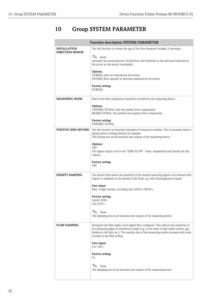
INSTALLATION
DIRECTION SENSOR
Use this function to reverse the sign of the flow measured variable, if necessary.
! Note!
Ascertain the actual direction of fluid flow with reference to the direction indicated by
the arrow on the sensor (nameplate).
Options:
NORMAL (flow as indicated by the arrow)
INVERSE (flow opposite to direction indicated by the arrow)
Factory setting:
NORMAL
MEASURING MODE Select how flow components should be recorded by the measuring device.
Options:
UNIDIRECTIONAL (only the positive flow components)
BIDIRECTIONAL (the positive and negative flow components)
Factory setting:
UNIDIRECTIONAL
POSITIVE ZERO RETURN Use this function to interrupt evaluation of measured variables. This is necessary when a
piping system is being cleaned, for example.
This setting acts on all functions and outputs of the measuring device.
Options:
OFF
ON (signal output is set to the “ZERO FLOW ” value, temperature and density are still
output).
Factory setting:
OFF
DENSITY DAMPING The density filter allows the sensitivity of the density measuring signal to be lowered with
respect to variations in the density of the fluid, e.g. with inhomogeneous liquids.
User input:
Max. 5-digit number, including unit: 0.00 to 100.00 s
Factory setting:
Liquid: 0.00 s
Gas: 0.25 s
! Note!
The damping acts on all functions and outputs of the measuring device.
FLOW DAMPING Setting for the filter depth of the digital filter configured. This reduces the sensitivity of
the measuring signal to interference peaks (e.g. in the event of high solids content, gas
bubbles in the fluid, etc.). The reaction time of the measuring system increases with every
increase in the filter setting.
User input:
0 to 100 s
Factory setting:
0 s
! Note!
The damping acts on all functions and outputs of the measuring device.

Device Functions Proline Promass 80 PROFIBUS PA 11 Group SENSOR DATA
33
11 Group SENSOR DATA
Function description SENSOR DATA
All sensor data (calibration factor, zero point, nominal diameter etc.) are set at the factory and saved on the S-DAT sensor
memory chip.
" Caution!
Under normal circumstances you should not change the following parameter settings, because changes affect numerous
functions of the entire measuring facility in general and the accuracy of the measuring system in particular. For this
reason, the functions described below cannot be changed even when you enter your personal code.
Contact the Endress+Hauser service organization if you have any questions about these functions.
K-FACTOR Use this function to display the current calibration factor for the sensor.
Factory setting:
Depends on nominal diameter and calibration.
! Note!
If the function is called via the service code, this value can be edited.
ZERO POINT Use this function to display the current zero point correction value for the sensor.
User input:
max. 5-digit number: –99999 to +99999
Factory setting:
Depends on calibration
NOMINAL DIAMETER This function shows the nominal diameter for the sensor.
Factory setting:
Depends on the size of the sensor
! Note!
If the function is called via the service code, this value can be edited.
TEMPERATURE
COEFFICIENT KM
Use this function to display the temperature coefficient KM.
TEMPERATURE
COEFFICIENT KM 2
Use this function to display the temperature coefficient KM 2.
TEMPERATURE
COEFFICIENT KT
Use this function to display the temperature coefficient KT.
CALIBRATION
COEFFICIENT KD 1
Use this function to display the calibration coefficient KD 1.
CALIBRATION
COEFFICIENT KD 2
Use this function to display the calibration coefficient KD 2.
DENSITY COEFFICIENT
C0
Use this function to display the current density coefficient C 0.
" Caution!
A field density adjustment can alter the value of the density coefficient.

11 Group SENSOR DATA Device Functions Proline Promass 80 PROFIBUS PA
34
DENSITY COEFFICIENT
C1
Use this function to display the current density coefficient C 1.
" Caution!
A field density adjustment can alter the value of the density coefficient.
DENSITY COEFFICIENT
C2
Use this function to display the current density coefficient C 2.
" Caution!
A field density adjustment can alter the value of the density coefficient.
DENSITY COEFFICIENT
C3
Use this function to display the current density coefficient C 3.
" Caution!
A field density adjustment can alter the value of the density coefficient.
DENSITY COEFFICIENT
C4
Use this function to display the current density coefficient C 4.
" Caution!
A field density adjustment can alter the value of the density coefficient.
DENSITY COEFFICIENT
C5
Use this function to display the current density coefficient C 5.
" Caution!
A field density adjustment can alter the value of the density coefficient.
MINIMUM FLUID
TEMPERATURE
Use this function to display the lowest fluid temperature measured.
MAXIMUM FLUID
TEMPERATURE
Use this function to display the highest fluid temperature measured.
MINIMUM CARRIER
TUBE TEMPERATURE
Use this function to display the lowest carrier tube temperature measured.
MAXIMUM CARRIER
TUBE TEMPERATURE
Use this function to display the highest carrier tube temperature measured.
Function description SENSOR DATA

Device Functions Proline Promass 80 PROFIBUS PA 12 Group SUPERVISION
35
12 Group SUPERVISION
Function description SUPERVISION
ACTUAL SYSTEM
CONDITION
Use this function to display the current system condition.
Display:
“SYSTEM OK” or the fault / notice message with the highest priority.
PREVIOUS SYSTEM
CONDITIONS
Use this function to view the fifteen most recent fault and notice messages since
measuring last started.
Display:
The 15 most recent fault or notice messages.
ALARM DELAY Use this function to enter a time span for which the criteria for an error have to be
satisfied without interruption before a fault or notice message is generated.
Depending on the setting and the type of fault, this suppression acts on:
• Display
• PROFIBUS PA
User input:
0 to 100 s (in steps of one second)
Factory setting:
0 s
" Caution!
If this function is activated, fault and notice messages are delayed by the time
corresponding to the setting before being transmitted to the higher-order controller
(process controller, etc.). It is therefore imperative to check in advance in order to make
sure whether a delay of this nature could affect the safety requirements of the process.
If fault and notice messages may not be suppressed, a value of 0 seconds must be entered
here.
SYSTEM RESET Use this function to reset the measuring system.
Options:
NO
RESTART SYSTEM (restart without interrupting power supply)
Factory setting:
NO
OPERATION HOURS The hours of operation of the device appear on the display.
Display:
Depends on the number of hours of operation elapsed:
Hours of operation < 10 hours → display format = 0:00:00 (hr:min:sec)
Hours of operation 10 to 10,000 hours → display format = 0000:00 (hr:min)
Hours of operation > 10,000 hours → display format = 000000 (hr)
STORAGE Displays whether permanent storage of all the parameters in the EEPROM is switched on
or off.
Display:
OFF
ON
Factory setting:
ON

13 Group SIMULATION SYSTEM Device Functions Proline Promass 80 PROFIBUS PA
36
13 Group SIMULATION SYSTEM
Function description SIMULATION SYSTEM
SIMULATION FAILSAFE
MODE
Use this function to set all inputs, outputs and the totalizer to their defined error-response
modes, in order to check whether they respond correctly. During this time, the message
“SIMULATION FAILSAFE MODE” appears on the display.
Options:
OFF
ON
Factory setting:
OFF
SIMULATION
MEASURAND
Use this function to set all inputs, outputs and the totalizer to their defined flow-response
modes, in order to check whether they respond correctly. During this time, the message
“SIMULATION MEASURAND” appears on the display.
Options:
OFF
MASS FLOW
VOLUME FLOW
CORRECTED VOLUME FLOW
DENSITY
REFERENCE DENSITY
TEMPERATURE
Factory setting:
OFF
" Caution!
• The measuring device cannot be used for measuring while this simulation is in
progress.
• The setting is not saved in the event of a power failure.
VALUE SIMULATION
MEASURAND ! Note!
This function is not available unless the SIMULATION MEASURAND function is active.
Use this function to specify a selectable value (e.g. 12 kg/s). This value is used to test
downstream devices and the measuring device itself.
User input:
5-digit floating-point number
Factory setting:
0 kg/h (MASS FLOW)
0 m3/h (VOLUME FLOW)
0 Nm3/h(CORRECTED VOLUME FLOW)
0 kg/l(DENSITY)
0 kg/NI(REFERENCE DENSITY)
0 °C(TEMPERATURE)
" Caution!
The setting is not saved in the event of a power failure.

Device Functions Proline Promass 80 PROFIBUS PA 14 Group SENSOR VERSION
37
14 Group SENSOR VERSION
15 Group AMPLIFIER VERSION
Function description SENSOR VERSION
SERIAL NUMBER Use this function to view the serial number of the sensor.
SENSOR TYPE Use this function to view the sensor type (e.g. Promass F).
SOFTWARE REVISION
NUMBER
S-DAT
Use this function to view the software revision number of the software used to create the
content of the S-DAT.
Function description AMPLIFIER VERSION
SOFTWARE REVISION
NUMBER AMPLIFIER
Use this function to view the software revision number of the amplifier.
LANGUAGE GROUP Use this function to view the language group.
The following language groups can be ordered: WEST EU / USA, EAST EU / SCAND.,
ASIA, CHINA.
Display:
available language group
! Note!
• The language options of the available language group are displayed in the LANGUAGE
function.
• You can change the language group via the configuration software FieldCare. Please do
not hesitate to contact your Endress+Hauser sales office if you have any questions.
I/O MODULE TYPE Use this function to display the I/O module type.
SOFTWARE REVISION
NUMBER I/O MODULE
Use this function to view the software revision number of the I/O module.

16 Factory settings Device Functions Proline Promass 80 PROFIBUS PA
38
16 Factory settings
16.1 SI units (not for USA and Canada)
16.1.1 Low flow cutoff, full scale value – Liquid
16.1.2 Low flow cutoff, full scale value – Gas
Nom. diameter Low flow cut off Full scale value Pulse value
[mm] (approx. v = 0.04 m/s) (approx. v = 2 m/s) (approx. 2 pulse/s at 2 m/s)
1 0.08 kg/h 4 kg/h 0.001 kg/p
2 0.40 kg/h 20 kg/h 0.010 kg/p
4 1.80 kg/h 90 kg/h 0.010 kg/p
8 8.00 kg/h 400 kg/h 0.100 kg/p
15 26.00 kg/h 1300 kg/h 0.100 kg/p
15 FB 72.00 kg/h 3600 kg/h 1.000 kg/p
25 72.00 kg/h 3600 kg/h 1.000 kg/p
25 FB 180.00 kg/h 9000 kg/h 1.000 kg/p
40 180.00 kg/h 9000 kg/h 1.000 kg/p
40 FB 300.00 kg/h 15000 kg/h 10.000 kg/p
50 300.00 kg/h 15000 kg/h 10.000 kg/p
50 FB 720.00 kg/h 36000 kg/h 10.000 kg/p
80 720.00 kg/h 36000 kg/h 10.000 kg/p
100 1200.00 kg/h 60000 kg/h 10.000 kg/p
150 2600.00 kg/h 130000 kg/h 100.000 kg/p
250 7200.00 kg/h 360000 kg/h 100.000 kg/p
DN 15, 25, 40, 50 “FB” = Full bore versions Promass I
Nom. diameter Low flow cut off Full scale value Pulse value
[mm] (approx. v = 0.01 m/s) (approx. v = 2 m/s) (approx. 2 pulse/s at 2 m/s)
1 0.02 kg/h 4 kg/h 0.001 kg/p
2 0.10 kg/h 20 kg/h 0.010 kg/p
4 0.45 kg/h 90 kg/h 0.010 kg/p
8 2.00 kg/h 400 kg/h 0.100 kg/p
15 6.50 kg/h 1300 kg/h 0.100 kg/p
15 FB 18.00 kg/h 3600 kg/h 1.000 kg/p
25 18.00 kg/h 3600 kg/h 1.000 kg/p
25 FB 45.00 kg/h 9000 kg/h 1.000 kg/p
40 45.00 kg/h 9000 kg/h 1.000 kg/p
40 FB 75.00 kg/h 15000 kg/h 10.000 kg/p
50 75.00 kg/h 15000 kg/h 10.000 kg/p
50 FB 180.00 kg/h 36000 kg/h 10.000 kg/p
80 180.00 kg/h 36000 kg/h 10.000 kg/p
100 300.00 kg/h 60000 kg/h 10.000 kg/p
150 650.00 kg/h 130000 kg/h 100.000 kg/p
250 1800.00 kg/h 360000 kg/h 100.000 kg/p
DN 15, 25, 40, 50 “FB” = Full bore versions Promass I

Device Functions Proline Promass 80 PROFIBUS PA 16 Factory settings
39
16.1.3 Language
16.1.4 Density, length, temperature
Country Language
Australia English
Austria Deutsch
Belgium Francais
Denmark Dansk
England English
Finland Suomi
France Francais
Germany Deutsch
Hong Kong English
Hungary English
India English
Instruments International English
Italy Italiano
Japan Japanese
Malaysia English
Netherlands Nederlands
Norway Norsk
Singapore English
South Africa English
Spain Espanol
Sweden Svenska
Switzerland Deutsch
Thailand English
Unit
Density kg/l
Length mm
Temperature ° C

16 Factory settings Device Functions Proline Promass 80 PROFIBUS PA
40
16.2 US units (only for USA and Canada)
16.2.1 Low flow, full scale value – Liquid
16.2.2 Low flow, full scale value – Gas
16.2.3 Language, density, length, temperature
Nominal
diameterLow flow cut off Full scale value Pulse value
[mm] (approx. v = 0.04 m/s) (approx. v = 2 m/s) (approx. 2 pulse/s at 2 m/s)
1 0.003 lb/min 0.15 lb/min 0.002 lb/p
2 0.015 lb/min 0.75 lb/min 0.020 lb/p
4 0.066 lb/min 3.30 lb/min 0.020 lb/p
8 0.300 lb/min 15.00 lb/min 0.200 lb/p
15 1.000 lb/min 50.00 lb/min 0.200 lb/p
15 FB 2.600 lb/min 130.00 lb/min 2.000 lb/p
25 2.600 lb/min 130.00 lb/min 2.000 lb/p
25 FB 6.600 lb/min 330.00 lb/min 2.000 lb/p
40 6.600 lb/min 330.00 lb/min 2.000 lb/p
40 FB 11.000 lb/min 550.00 lb/min 20.000 lb/p
50 11.000 lb/min 550.00 lb/min 20.000 lb/p
50 FB 26.000 lb/min 1300.00 lb/min 20.000 lb/p
80 26.000 lb/min 1300.00 lb/min 20.000 lb/p
100 44.000 lb/min 2200.00 lb/min 20.000 lb/p
150 95.000 lb/min 4800.00 lb/min 200.000 lb/p
250 260.00 lb/min 13000.00 lb/min 200.000 lb/p
DN 15, 25, 40, 50 “FB” = Full bore versions Promass I
Nominal
diameterLow flow cut off Full scale value Pulse value
[mm] (approx. v = 0.01 m/s) (approx. v = 2 m/s) (approx. 2 pulse/s at 2 m/s)
1 0.001 lb/min 0.15 lb/min 0.002 lb/p
2 0.004 lb/min 0.75 lb/min 0.020 lb/p
4 0.046 lb/min 3.30 lb/min 0.020 lb/p
8 0.075 lb/min 15.00 lb/min 0.200 lb/p
15 0.250 lb/min 50.00 lb/min 0.200 lb/p
15 FB 0.650 lb/min 130.00 lb/min 2.000 lb/p
25 0.650 lb/min 130.00 lb/min 2.000 lb/p
25 FB 1.650 lb/min 330.00 lb/min 2.000 lb/p
40 1.650 lb/min 330.00 lb/min 2.000 lb/p
40 FB 2.750 lb/min 550.00 lb/min 20.000 lb/p
50 2.750 lb/min 550.00 lb/min 20.000 lb/p
50 FB 6.500 lb/min 1300.00 lb/min 20.000 lb/p
80 6.500 lb/min 1300.00 lb/min 20.000 lb/p
100 11.000 lb/min 2200.00 lb/min 20.000 lb/p
150 23.750 lb/min 4800.00 lb/min 200.000 lb/p
250 65.000 lb/min 13000.00 lb/min 200.000 lb/p
DN 15, 25, 40, 50 “FB” = Full bore versions Promass I
Unit
Language English
Density g/cc
Length Inch
Temperature ° F

Device Functions Proline Promass 80 PROFIBUS PA Index
41
Index
Numerics100% value, line 1 and 2 . . . . . . . . . . . . . . . . . . . . . . . . . 19
AAccess code . . . . . . . . . . . . . . . . . . . . . . . . . . . . . . . . . . . 17Access code counter . . . . . . . . . . . . . . . . . . . . . . . . . . . . . 17Actual baud rate . . . . . . . . . . . . . . . . . . . . . . . . . . . . . . . . 25Actual system condition . . . . . . . . . . . . . . . . . . . . . . . . . . 35Adjustment
Density . . . . . . . . . . . . . . . . . . . . . . . . . . . . . . . . . . . . 30Zero point . . . . . . . . . . . . . . . . . . . . . . . . . . . . . . . . . . 29
Alarm delay . . . . . . . . . . . . . . . . . . . . . . . . . . . . . . . . . . . 35Assign
Display on line 1 and 2 . . . . . . . . . . . . . . . . . . . . . . . . 18Low flow cut off . . . . . . . . . . . . . . . . . . . . . . . . . . . . . 27
BBacklight . . . . . . . . . . . . . . . . . . . . . . . . . . . . . . . . . . . . . 20Block selection . . . . . . . . . . . . . . . . . . . . . . . . . . . . . . . . . 25Bus address . . . . . . . . . . . . . . . . . . . . . . . . . . . . . . . . . . . 24
CCalibration coefficient KD1, KD2 . . . . . . . . . . . . . . . . . . . 33Carrier tube temperature
Maximum . . . . . . . . . . . . . . . . . . . . . . . . . . . . . . . . . 34Minimum . . . . . . . . . . . . . . . . . . . . . . . . . . . . . . . . . . 34
Channel . . . . . . . . . . . . . . . . . . . . . . . . . . . . . . . . . . . . . . 21Function blocks . . . . . . . . . . . . . . . . . . . . . . . . . . . . . 26
Check configuration . . . . . . . . . . . . . . . . . . . . . . . . . . . . . 25Coefficients
Calibration KD1, KD2 . . . . . . . . . . . . . . . . . . . . . . . . . 33Density C 0 to 5 . . . . . . . . . . . . . . . . . . . . . . . . . . . . . 33Temperature KM, KM2, KT . . . . . . . . . . . . . . . . . . . . 33
Contrast LCD . . . . . . . . . . . . . . . . . . . . . . . . . . . . . . . . . . 19Corrected volume . . . . . . . . . . . . . . . . . . . . . . . . . . . . . . 10Corrected volume flow . . . . . . . . . . . . . . . . . . . . . . . . . . . . 7CYCL. CALC. TOT. . . . . . . . . . . . . . . . . . . . . . . . . . . . . . 23
DDamping
Density . . . . . . . . . . . . . . . . . . . . . . . . . . . . . . . . . . . . 32Display . . . . . . . . . . . . . . . . . . . . . . . . . . . . . . . . . . . . 19Flow . . . . . . . . . . . . . . . . . . . . . . . . . . . . . . . . . . . . . . 32
Define private code . . . . . . . . . . . . . . . . . . . . . . . . . . . . . 17Density . . . . . . . . . . . . . . . . . . . . . . . . . . . . . . . . . . . . . . . 7Density adjustment . . . . . . . . . . . . . . . . . . . . . . . . . . . . . 30Density coefficient C 0 to 5 . . . . . . . . . . . . . . . . . . . . . . . 33Density set point . . . . . . . . . . . . . . . . . . . . . . . . . . . . . . . 29Device ID . . . . . . . . . . . . . . . . . . . . . . . . . . . . . . . . . . . . . 25Display
Damping . . . . . . . . . . . . . . . . . . . . . . . . . . . . . . . . . . 19Test . . . . . . . . . . . . . . . . . . . . . . . . . . . . . . . . . . . . . . 20
Display illumination (background illumination) . . . . . . . . . 20Display value . . . . . . . . . . . . . . . . . . . . . . . . . . . . . . . . . . 26
EEmpty pipe detection
EPD . . . . . . . . . . . . . . . . . . . . . . . . . . . . . . . . . . . . . . 28EPD response time . . . . . . . . . . . . . . . . . . . . . . . . . . . 28EPD value high . . . . . . . . . . . . . . . . . . . . . . . . . . . . . . 28EPD value low . . . . . . . . . . . . . . . . . . . . . . . . . . . . . . 28
FFactory settings
Full scale value . . . . . . . . . . . . . . . . . . . . . . . . . . . . . . 38Low flow . . . . . . . . . . . . . . . . . . . . . . . . . . . . . . . . . . 38Pulse value . . . . . . . . . . . . . . . . . . . . . . . . . . . . . . . . . 38
Failsafe modeSimulation . . . . . . . . . . . . . . . . . . . . . . . . . . . . . . . . . 36
Fixed reference density . . . . . . . . . . . . . . . . . . . . . . . . . . . 28Function matrix
Layout and operation . . . . . . . . . . . . . . . . . . . . . . . . . . . 5Overview . . . . . . . . . . . . . . . . . . . . . . . . . . . . . . . . . . . 6
GGroup
Amplifier version . . . . . . . . . . . . . . . . . . . . . . . . . . . . . 37Communication . . . . . . . . . . . . . . . . . . . . . . . . . . . . . 24Display . . . . . . . . . . . . . . . . . . . . . . . . . . . . . . . . . . . . 18Measuring values . . . . . . . . . . . . . . . . . . . . . . . . . . . . . 7Operation . . . . . . . . . . . . . . . . . . . . . . . . . . . . . . . . . . 16Process parameter . . . . . . . . . . . . . . . . . . . . . . . . . . . . 27Quick Setup . . . . . . . . . . . . . . . . . . . . . . . . . . . . . . . . 13Sensor data . . . . . . . . . . . . . . . . . . . . . . . . . . . . . . . . . 33Sensor version . . . . . . . . . . . . . . . . . . . . . . . . . . . . . . . 37Simulation system . . . . . . . . . . . . . . . . . . . . . . . . . . . . 36Supervision . . . . . . . . . . . . . . . . . . . . . . . . . . . . . . . . . 35System parameter . . . . . . . . . . . . . . . . . . . . . . . . . . . . 32System units . . . . . . . . . . . . . . . . . . . . . . . . . . . . . . . . . 8Totalizer . . . . . . . . . . . . . . . . . . . . . . . . . . . . . . . . . . . 21
IInstallation direction sensor . . . . . . . . . . . . . . . . . . . . . . . 32
KK-Factor . . . . . . . . . . . . . . . . . . . . . . . . . . . . . . . . . . . . . . 33
LLanguage . . . . . . . . . . . . . . . . . . . . . . . . . . . . . . . . . . . . . 16
Language group (display) . . . . . . . . . . . . . . . . . . . . . . . 37Language group . . . . . . . . . . . . . . . . . . . . . . . . . . . . . . . . 37LCD contrast . . . . . . . . . . . . . . . . . . . . . . . . . . . . . . . . . . 19Low flow cut off
Assign . . . . . . . . . . . . . . . . . . . . . . . . . . . . . . . . . . . . . 27Off value . . . . . . . . . . . . . . . . . . . . . . . . . . . . . . . . . . . 27On value . . . . . . . . . . . . . . . . . . . . . . . . . . . . . . . . . . . 27
MMass flow . . . . . . . . . . . . . . . . . . . . . . . . . . . . . . . . . . . . . . 7Maximum
Carrier tube temperature . . . . . . . . . . . . . . . . . . . . . . . 34Medium temperature . . . . . . . . . . . . . . . . . . . . . . . . . 34
Measure fluid . . . . . . . . . . . . . . . . . . . . . . . . . . . . . . . . . . 29Measuring mode . . . . . . . . . . . . . . . . . . . . . . . . . . . . . . . . 32

Index Device Functions Proline Promass 80 PROFIBUS PA
42
Medium temperatureMaximum . . . . . . . . . . . . . . . . . . . . . . . . . . . . . . . . . 34Minimum . . . . . . . . . . . . . . . . . . . . . . . . . . . . . . . . . 34
MinimumCarrier tube temperature . . . . . . . . . . . . . . . . . . . . . . 34Medium temperature . . . . . . . . . . . . . . . . . . . . . . . . . 34
NNominal diameter . . . . . . . . . . . . . . . . . . . . . . . . . . . . . . 33
OOff-value low flow cut off . . . . . . . . . . . . . . . . . . . . . . . . 27On-value low flow cut off . . . . . . . . . . . . . . . . . . . . . . . . 27Operation hours . . . . . . . . . . . . . . . . . . . . . . . . . . . . . . . 35OUT value 1 . . . . . . . . . . . . . . . . . . . . . . . . . . . . . . . . . . 25Output value 1 . . . . . . . . . . . . . . . . . . . . . . . . . . . . . . . . 25Overflow . . . . . . . . . . . . . . . . . . . . . . . . . . . . . . . . . . . . . 21
PPositive zero return . . . . . . . . . . . . . . . . . . . . . . . . . . . . . 32Preset totalizer . . . . . . . . . . . . . . . . . . . . . . . . . . . . . . . . 22Pressure . . . . . . . . . . . . . . . . . . . . . . . . . . . . . . . . . . . . . 31Pressure mode . . . . . . . . . . . . . . . . . . . . . . . . . . . . . . . . . 30Previous system conditions . . . . . . . . . . . . . . . . . . . . . . . 35Profile version . . . . . . . . . . . . . . . . . . . . . . . . . . . . . . . . . 25
QQuick Setup
Commission . . . . . . . . . . . . . . . . . . . . . . . . . . . . . . . . 13Communication . . . . . . . . . . . . . . . . . . . . . . . . . . . . . 13
RReference density . . . . . . . . . . . . . . . . . . . . . . . . . . . . . . . 7Reference density (fixed) . . . . . . . . . . . . . . . . . . . . . . . . . 28Reset system . . . . . . . . . . . . . . . . . . . . . . . . . . . . . . . . . . 35Restore original coefficients . . . . . . . . . . . . . . . . . . . . . . . 30
SSelect totalizer . . . . . . . . . . . . . . . . . . . . . . . . . . . . . . . . . 21Selection GSD . . . . . . . . . . . . . . . . . . . . . . . . . . . . . . . . . 24Sensor serial number . . . . . . . . . . . . . . . . . . . . . . . . . . . . 37Sensor type . . . . . . . . . . . . . . . . . . . . . . . . . . . . . . . . . . . 37Set totalizer . . . . . . . . . . . . . . . . . . . . . . . . . . . . . . . . . . . 22Set unit to bus . . . . . . . . . . . . . . . . . . . . . . . . . . . . . . . . . 24Simulation
Measured variable . . . . . . . . . . . . . . . . . . . . . . . . . . . 36Simulation failsafe mode . . . . . . . . . . . . . . . . . . . . . . . . . 36Software revision number
Amplifier . . . . . . . . . . . . . . . . . . . . . . . . . . . . . . . . . . 37I/O module . . . . . . . . . . . . . . . . . . . . . . . . . . . . . . . . 37S-DAT . . . . . . . . . . . . . . . . . . . . . . . . . . . . . . . . . . . . 37
Status access . . . . . . . . . . . . . . . . . . . . . . . . . . . . . . . . . . 17Storage . . . . . . . . . . . . . . . . . . . . . . . . . . . . . . . . . . . . . . .35System
Actual condition . . . . . . . . . . . . . . . . . . . . . . . . . . . . . 35Previous conditions . . . . . . . . . . . . . . . . . . . . . . . . . . 35Reset . . . . . . . . . . . . . . . . . . . . . . . . . . . . . . . . . . . . . 35
TTag name . . . . . . . . . . . . . . . . . . . . . . . . . . . . . . . . . . . . 24Temperature . . . . . . . . . . . . . . . . . . . . . . . . . . . . . . . . . . . 7Temperature coefficient KM, KM2, KT . . . . . . . . . . . . . . . 33Test display . . . . . . . . . . . . . . . . . . . . . . . . . . . . . . . . . . . 20Totalizer
Channel . . . . . . . . . . . . . . . . . . . . . . . . . . . . . . . . . . . 21Overflow . . . . . . . . . . . . . . . . . . . . . . . . . . . . . . . . . . 21Preset totalizer . . . . . . . . . . . . . . . . . . . . . . . . . . . . . . 22Selection . . . . . . . . . . . . . . . . . . . . . . . . . . . . . . . . . . 21Set totalizer . . . . . . . . . . . . . . . . . . . . . . . . . . . . . . . . 22Totalizer mode . . . . . . . . . . . . . . . . . . . . . . . . . . . . . . 22Unit . . . . . . . . . . . . . . . . . . . . . . . . . . . . . . . . . . . . . . 21
Totalizer mode . . . . . . . . . . . . . . . . . . . . . . . . . . . . . . . . 22Type I/O Module . . . . . . . . . . . . . . . . . . . . . . . . . . . . . . 37
UUnit
Corrected volume . . . . . . . . . . . . . . . . . . . . . . . . . . . 10Corrected volume flow . . . . . . . . . . . . . . . . . . . . . . . . 10Density . . . . . . . . . . . . . . . . . . . . . . . . . . . . . . . . . . . 11Length . . . . . . . . . . . . . . . . . . . . . . . . . . . . . . . . . . . . 11Mass . . . . . . . . . . . . . . . . . . . . . . . . . . . . . . . . . . . . . . 8Mass flow . . . . . . . . . . . . . . . . . . . . . . . . . . . . . . . . . . 8Pressure . . . . . . . . . . . . . . . . . . . . . . . . . . . . . . . . . . . 12Reference density . . . . . . . . . . . . . . . . . . . . . . . . . . . . 11Temperature . . . . . . . . . . . . . . . . . . . . . . . . . . . . . . . 11Volume . . . . . . . . . . . . . . . . . . . . . . . . . . . . . . . . . . . . 9Volume flow . . . . . . . . . . . . . . . . . . . . . . . . . . . . . . . . 9
Unit totalizer . . . . . . . . . . . . . . . . . . . . . . . . . . . . . . . . . . 21
VValue simulation measurand . . . . . . . . . . . . . . . . . . . . . . 36Version
Amplifier . . . . . . . . . . . . . . . . . . . . . . . . . . . . . . . . . . 37Sensor . . . . . . . . . . . . . . . . . . . . . . . . . . . . . . . . . . . . 37
Volume flow . . . . . . . . . . . . . . . . . . . . . . . . . . . . . . . . . . . 7
WWrite protect . . . . . . . . . . . . . . . . . . . . . . . . . . . . . . . . . . 24
ZZero point . . . . . . . . . . . . . . . . . . . . . . . . . . . . . . . . . . . . 33Zero point adjustment . . . . . . . . . . . . . . . . . . . . . . . . . . . 29

Device Functions Proline Promass 80 PROFIBUS PA Index
43

Printed in U.S.A. © 5/09 FMC Technologies Measurement Solutions, Inc. All rights reserved. MN0M029 Issue/Rev. 0.0 (5/09)
Visit our website at www.fmctechnologies.com/measurementsolutions
The specifications contained herein are subject to change without notice and any user of said specifications should verify from the manufacturer that the specifications are currently in effect. Otherwise, the manufacturer assumes no responsibility for the use of specifications which may have been changed and are no longer in effect.
Headquarters:500 North Sam Houston Parkway West, Suite 100, Houston, TX 77067 USA, Phone: +1 (281) 260-2190, Fax: +1 (281) 260-2191
Gas Measurement Products: Erie, PA USA +1 (814) 898-5000Ellerbek, Germany +49 (4101) 304-0Thetford, England +44 (1842) 82-2900Kongsberg, Norway +47 (32) 286-700Buenos Aires, Argentina +54 (11) 4312-4736
Integrated Measurement Systems:Corpus Christi, TX USA +1 (361) 289-3400Kongsberg, Norway +47 (32) 286-700San Juan, Puerto Rico +1809 (787) 274-3760United Arab Emirates, Dubai +971 (4) 331-3646
Liquid Measurement Products:Erie, PA USA +1 (814) 898-5000Los Angeles, CA USA +1 (310) 328-1236 Slough, England +44 (1753) 57-1515Ellerbek, Germany +49 (4101) 304-0Barcelona, Spain +34 (93) 201-0989Moscow, Russia +7 (495) 564-8705Melbourne, Australia +61 (3) 9807-2818
Beijing, China +86 (10) 6500-2251Singapore +65 6861-3011Chennai, India +91 (44) 450-4400