Coriolis Flow Meter - Graco · The meter uses the Coriolis principle to measure mass flow and fluid...
16
3A5295B EN Instructions - Parts Coriolis Flow Meter For measuring fluid flow and temperature with PCF ™ precision dispense systems in a non-hazardous location only. For professional use only. Not approved for use in explosive atmospheres or hazardous locations. 5000 psi (35 MPa, 345 bar) Maximum Fluid Working Pressure See page 2 for model information, including maximum working pressure and approvals. Important Safety Instructions Read all warnings and instructions in this manual. Save these instructions.
Transcript of Coriolis Flow Meter - Graco · The meter uses the Coriolis principle to measure mass flow and fluid...

3A5295BEN
Instructions - Parts
Coriolis Flow Meter
For measuring fluid flow and temperature with PCF™ precision dispense systems in a non-hazardous location only. For professional use only.
Not approved for use in explosive atmospheres or hazardous locations.
5000 psi (35 MPa, 345 bar) Maximum Fluid Working Pressure
See page 2 for model information, includingmaximum working pressure and approvals.
Important Safety InstructionsRead all warnings and instructions in this manual. Save these instructions.

Related Manuals
2 3A5295B
ContentsRelated Manuals . . . . . . . . . . . . . . . . . . . . . . . . . . . 2Warnings . . . . . . . . . . . . . . . . . . . . . . . . . . . . . . . . . 3Installation . . . . . . . . . . . . . . . . . . . . . . . . . . . . . . . . 5
Overview . . . . . . . . . . . . . . . . . . . . . . . . . . . . . . . 5Installation Requirements . . . . . . . . . . . . . . . . . . 5Mounting . . . . . . . . . . . . . . . . . . . . . . . . . . . . . . . 6Fluid Line Connection . . . . . . . . . . . . . . . . . . . . . 7Grounding . . . . . . . . . . . . . . . . . . . . . . . . . . . . . . 7Sensor Connector Pin-out . . . . . . . . . . . . . . . . . . 7
Operation . . . . . . . . . . . . . . . . . . . . . . . . . . . . . . . . . 8Pressure Relief Procedure . . . . . . . . . . . . . . . . . 8Recommended Usage . . . . . . . . . . . . . . . . . . . . . 8Flow Volume Range . . . . . . . . . . . . . . . . . . . . . . 8Flow Meter Calibration . . . . . . . . . . . . . . . . . . . . . 8
Maintenance . . . . . . . . . . . . . . . . . . . . . . . . . . . . . . . 9Flushing the Meter . . . . . . . . . . . . . . . . . . . . . . . . 9
Troubleshooting . . . . . . . . . . . . . . . . . . . . . . . . . . . 10Parts . . . . . . . . . . . . . . . . . . . . . . . . . . . . . . . . . . . . 11Kits and Accessories . . . . . . . . . . . . . . . . . . . . . . . 12Technical Specifications . . . . . . . . . . . . . . . . . . . . 13Graco Standard Warranty . . . . . . . . . . . . . . . . . . . 16Graco Information . . . . . . . . . . . . . . . . . . . . . . . . . 16
Models
Related Manuals
Part No. For Use WithMaximum Working Pressure
psi (MPa, bar) Description25D026 PCF 5000 psi (35 MPa, 345 bar) TRICOR® TCM 5500
Manuals
Part Description
3A2098 PCF with PrecisionSwirl™ Instruc-tions-Parts Manual
313377 PCF Instructions-Parts Manual
TCM_E80_M_EN_160520_E006
TRICOR Coriolis Mass Flow Meters Instruction Manual

Warnings
3A5295B 3
WarningsThe following warnings are for the setup, use, grounding, maintenance, and repair of this equipment. The exclama-tion point symbol alerts you to a general warning and the hazard symbols refer to procedure-specific risks. When these symbols appear in the body of this manual or on warning labels, refer back to these Warnings. Product-specific hazard symbols and warnings not covered in this section may appear throughout the body of this manual where applicable.
WARNINGEQUIPMENT MISUSE HAZARDMisuse can cause death or serious injury.• Do not operate the unit when fatigued or under the influence of drugs or alcohol.• Do not exceed the maximum working pressure or temperature rating of the lowest rated system com-
ponent. See Technical Specifications in all equipment manuals.• Use fluids and solvents that are compatible with equipment wetted parts. See Technical Specifica-
tions in all equipment manuals. Read fluid and solvent manufacturer’s warnings. For complete infor-mation about your material, request Safety Data Sheets (SDSs) from distributor or retailer.
• Turn off all equipment and follow the Pressure Relief Procedure when equipment is not in use.• Check equipment daily. Repair or replace worn or damaged parts immediately with genuine manu-
facturer’s replacement parts only.• Do not alter or modify equipment. Alterations or modifications may void agency approvals and create
safety hazards.• Make sure all equipment is rated and approved for the environment in which you are using it.• Use equipment only for its intended purpose. Call you distributor for information.• Route hoses and cables away from traffic areas, sharp edges, moving parts, and hot surfaces.• Do not kink or over bend hoses or use hoses to pull equipment.• Keep children and animals away from work area.• Comply with all applicable safety regulations.
FIRE AND EXPLOSION HAZARDFlammable fumes, such as solvent and paint fumes, in work area can ignite or explode. Paint or solvent flowing through the equipment can cause static sparking. To help prevent fire and explosion:• Use equipment only in well-ventilated area.• Eliminate all ignition sources; such as pilot lights, cigarettes, portable electric lamps, and plastic drop
cloths (potential static sparking).• Ground all equipment in the work area. See Grounding instructions.• Never spray or flush solvent at high pressure.• Keep work area free of debris, including solvent, rags and gasoline.• Do not plug or unplug power cords, or turn power or light switches on or off when flammable fumes are
present.• Use only grounded hoses.• Hold gun firmly to side of grounded pail when triggering into pail. Do not use pail liners unless they are
anti-static or conductive.• Stop operation immediately if static sparking occurs or you feel a shock. Do not use equipment until
you identify and correct the problem.• Keep a working fire extinguisher in the work area.

Warnings
4 3A5295B
SKIN INJECTION HAZARDHigh-pressure fluid from dispensing device, hose leaks, or ruptured components will pierce skin. This may look like just a cut, but it is a serious injury that can result in amputation. Get immediate surgical treatment.• Engage trigger lock when not dispensing.• Do not point dispensing device at anyone or at any part of the body.• Do not put your hand over the fluid outlet.• Do not stop or deflect leaks with your hand, body, glove, or rag.• Follow the Pressure Relief Procedure when you stop dispensing and before cleaning, checking, or
servicing equipment.• Tighten all fluid connections before operating the equipment.• Check hoses and couplings daily. Replace worn or damaged parts immediately.
TOXIC FLUID OR FUMES HAZARDToxic fluids or fumes can cause serious injury or death if splashed in the eyes or on skin, inhaled, or swallowed.• Read Safety Data Sheets (SDSs) to know the specific hazards of the fluids you are using.• Store hazardous fluid in approved containers, and dispose of it according to applicable guidelines.
BURN HAZARDEquipment surfaces and fluid that is heated can become very hot during operation. To avoid severe burns:• Do not touch hot fluid or equipment.
PERSONAL PROTECTIVE EQUIPMENTWear appropriate protective equipment when in the work area to help prevent serious injury, including eye injury, hearing loss, inhalation of toxic fumes, and burns. Protective equipment includes but is not limited to:• Protective eyewear, and hearing protection.• Respirators, protective clothing, and gloves as recommended by the fluid and solvent manufacturer.
WARNING

Installation
3A5295B 5
Installation
OverviewThe TRICOR® TCM 5500 flow meter provides a configu-rable and highly accurate means of measuring fluid flow. The meter uses the Coriolis principle to measure mass flow and fluid density, and also measures fluid tempera-ture using an integrated temperature sensor.
This manual provides information for using the TRICOR flow meter with the Graco PCF precision dispense sys-tems in non-IS systems. See manual TCM_E80_M_EN_160520_E006 provided by TRICOR for further meter instructions.
Installation Requirements
Fluid Supply
1. Avoid having solids enter the flow meter. Thor-oughly flush fluid supply lines before installing the meter.
2. Do not allow sealing tape to overlap inside pipe con-nections.
3. Use an adequately sized fluid line with a minimal number of restrictions (valves or bends) to avoid tur-bulence and cavitation.
Location
The meter measures the flow at the location it is installed, so install the flow meter as close as possible to the fluid regulator.
The meter must be located within 20 ft. (6.1 m) of the fluid plate. The Graco-provided meter signal cable assembly (4) must be used. No substitution is allowed.
NOTICETo prevent damaging electrical components, keep liquids away from the meter sensor.
NOTICETo prevent the buildup of static electricity, never use the flow meter with an electrostatic gun isola-tion stand.

Installation
6 3A5295B
MountingNOTE: A Coriolis flow meter only comes with PFxCxx assemblies.
Fluid Flow UpwardMounting so fluid flow is upward allows solids to settle out and air to rise away from the metering tube. See FIG. 1.
Horizontal InstallationThe horizontal installation is the recommended installa-tion.
If the medium might contain solid particles, mount the meter as shown in position A, and in all other cases mount as shown in position B.
NOTICESee Technical Specifications on page 13 for the weight of your meter. The meter is heavy and must be properly supported to avoid stress on the fluid connections.
FIG. 1: Fluid Flow Upward
Check Valve
FIG. 2:

Installation
3A5295B 7
Fluid Line Connection
Connect the fluid supply line to the meter inlet.
Connect the 5 ft (1.52 m) fluid hose from the meter out-let to the appropriate component A or B dispense valve.
Grounding
Always ground the fluid supply unit using one of the fol-lowing options:
a. Mount the meter to a grounded conductive sur-face.
b. Connect the conductive fluid hose to the meter inlet and outlet.
Sensor Connector Pin-out
Check hoses, tubes, and couplings daily. Tighten connections before operating. Replace worn or dam-aged parts immediately.
FIG. 3:
NOTE: This drawing shows the pin connector usedon the meter 25D026.
Pin 1: +10-30 Vdc SupplyPin 2: Signal OutPin 3: GroundPin 4: No Connection
2
4
1
3 Pin 5: No Connection5
Operation
8 3A5295B
Operation
Pressure Relief ProcedureFollow the Pressure Relief Procedure whenever you see this symbol.
1. Turn off the fluid supply to the meter.
2. Shut off all electrical power to the fluid system.
3. Follow the Pressure Relief Procedure for your PCF dispense system.
Recommended UsageSee Technical Specifications on page 13 for fluid and ambient temperature limits.
Only use the flow meter with fluids that are compatible with the “Wetted Parts” listed in the Technical Specifi-cations.
Flow Volume RangeSee Technical Specifications on page 13 for flow vol-ume range.
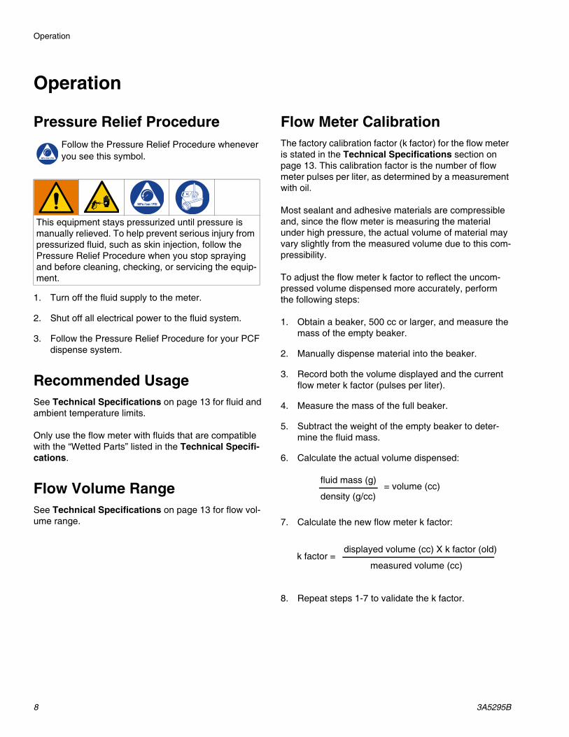
Flow Meter CalibrationThe factory calibration factor (k factor) for the flow meter is stated in the Technical Specifications section on page 13. This calibration factor is the number of flow meter pulses per liter, as determined by a measurement with oil.
Most sealant and adhesive materials are compressible and, since the flow meter is measuring the material under high pressure, the actual volume of material may vary slightly from the measured volume due to this com-pressibility.
To adjust the flow meter k factor to reflect the uncom-pressed volume dispensed more accurately, perform the following steps:
1. Obtain a beaker, 500 cc or larger, and measure the mass of the empty beaker.
2. Manually dispense material into the beaker.
3. Record both the volume displayed and the current flow meter k factor (pulses per liter).
4. Measure the mass of the full beaker.
5. Subtract the weight of the empty beaker to deter-mine the fluid mass.
6. Calculate the actual volume dispensed:
7. Calculate the new flow meter k factor:
8. Repeat steps 1-7 to validate the k factor.
This equipment stays pressurized until pressure is manually relieved. To help prevent serious injury from pressurized fluid, such as skin injection, follow the Pressure Relief Procedure when you stop spraying and before cleaning, checking, or servicing the equip-ment.
fluid mass (g)
density (g/cc)= volume (cc)
displayed volume (cc) X k factor (old)
measured volume (cc)k factor =

Maintenance
3A5295B 9
MaintenanceNOTE: Do not service the Coriolis meter or sensor. Return it to your Graco distributor for service.
Flushing the Meter
Flush the fluid supply line and meter fluid reservoir daily with a compatible solvent as instructed below.
1. Follow the Pressure Relief Procedure, on page 8.
2. Connect the fluid line to the solvent supply unit.
3. Flush the meter until it is clean.
4. Follow the Pressure Relief Procedure, and then disconnect the fluid line from the solvent supply unit.
To operate the meter after performing the flushing pro-cedure:
1. Reconnect the fluid line to the fluid supply.
2. Turn on the fluid supply.
3. Operate until the meter and fluid line are free of sol-vent.
NOTE: It is not recommended that the meter be oper-ated or flushed with water. Should this occur, residual water should be removed with alcohol and the internal components of the meter should be coated with a light film of oil. If the device is to remain inoperative for an extended period of time, internal components of the meter should be coated with a light film of oil.

Troubleshooting
10 3A5295B
Troubleshooting1. Follow Pressure Relief Procedure, page 8, before
checking or repairing flow meter.
2. Check all possible problems and causes before dis-assembling flow meter.
Problem Cause Solution
No flow volume displayed at monitor-ing unit.
Flow volume is too low to measure Increase flow volume.
Fluid is not flowing See Problem: fluid is not flowing, below.
Damaged cable Replace the cable.
Improper input voltage to sensor Make sure the input power is 10-30 Vdc.
Fluid is not flowing. Clogs in fluid line or in meter Clean the fluid line and/or meter; see Flushing the Meter on page 9.

Parts
3A5295B 11
Parts
25D026 Coriolis Flow Meter Assembly
Part No./Description
(Meter approved for use on PCF Platform)
101
104
103
102
Ref. Part Description Qty.101 129548 METER, TCM5500 1
BULKHEAD: 1/2 npt(m) x 08103 17T273 jic(m) 2103 100071 NUT, HEX 2104 502033 BUSHING, PIPE 2

Kits and Accessories
12 3A5295B
Kits and AccessoriesUse Only Genuine Graco Parts and Accessories
25D083 Replacement Electrical Cable
For connecting the sensor to the fluid plate.
17T319 Fixed Mounting Bracket
For mounting the flow meter.
17T320 Sliding Bracket Option
For mounting the flow meter.
Dimensions
18.11 in.
2.40 in.
11.42 in.
(46 cm)
(6.1 cm)
2x7.70 in.
(19.6 cm)
(29 cm)

Technical Specifications
3A5295B 13
Technical SpecificationsCoriolis Flow Meter
US MetricMaximum fluid working pressure 5000 psi 34.5 MPa, 345 barFluid Viscosity Range 30 - 1,000,000 cpsMaximum Cable Length 200 ft 60 mFlow Meter Inlet/Outlet 08 JIC (m)Accuracy +/- 0.25%*Repeatability +/- 0.1%Supply Voltage 10 - 30 VdcTypical Current 15mAApprovals CE: 25D026Wetted Parts 316 Stainless Steel, 440 SST, PTFEWeight 20 lb. 9 kgFlow Range 0.17 to 17.31 gpm 661 to 65,535 cc/minMaximum Operating Temperature 120° F 50° CMaximum Ambient Temperature 140° F 60° CCalibration Factor (K-Factor) 0.143 cc/pulse 7000 pulses/literNotes* For most commonly used coatings, the flow meter reading will be accurate to within +/- 0.25%. Accuracy
will diminish at low viscosities and low flow rates.

Technical Specifications
14 3A5295B

Technical Specifications
3A5295B 15
All written and visual data contained in this document reflects the latest product information available at the time of publication. Graco reserves the right to make changes at any time without notice.
Original instructions. This manual contains English. MM 3A5295Graco Headquarters: Minneapolis
International Offices: Belgium, China, Japan, Korea
GRACO INC. AND SUBSIDIARIES • P.O. BOX 1441 • MINNEAPOLIS MN 55440-1441 • USACopyright 2017, Graco Inc. All Graco manufacturing locations are registered to ISO 9001.
www.graco.comRevision B, December 2017
Graco Standard WarrantyGraco warrants all equipment referenced in this document which is manufactured by Graco and bearing its name to be free from defects in material and workmanship on the date of sale to the original purchaser for use. With the exception of any special, extended, or limited warranty published by Graco, Graco will, for a period of twelve months from the date of sale, repair or replace any part of the equipment determined by Graco to be defective. This warranty applies only when the equipment is installed, operated and maintained in accordance with Graco’s written recommendations.
This warranty does not cover, and Graco shall not be liable for general wear and tear, or any malfunction, damage or wear caused by faulty installation, misapplication, abrasion, corrosion, inadequate or improper maintenance, negligence, accident, tampering, or substitution of non-Graco component parts. Nor shall Graco be liable for malfunction, damage or wear caused by the incompatibility of Graco equipment with structures, accessories, equipment or materials not supplied by Graco, or the improper design, manufacture, installation, operation or maintenance of structures, accessories, equipment or materials not supplied by Graco.
This warranty is conditioned upon the prepaid return of the equipment claimed to be defective to an authorized Graco distributor for verification of the claimed defect. If the claimed defect is verified, Graco will repair or replace free of charge any defective parts. The equipment will be returned to the original purchaser transportation prepaid. If inspection of the equipment does not disclose any defect in material or workmanship, repairs will be made at a reasonable charge, which charges may include the costs of parts, labor, and transportation.
THIS WARRANTY IS EXCLUSIVE, AND IS IN LIEU OF ANY OTHER WARRANTIES, EXPRESS OR IMPLIED, INCLUDING BUT NOT LIMITED TO WARRANTY OF MERCHANTABILITY OR WARRANTY OF FITNESS FOR A PARTICULAR PURPOSE.
Graco’s sole obligation and buyer’s sole remedy for any breach of warranty shall be as set forth above. The buyer agrees that no other remedy (including, but not limited to, incidental or consequential damages for lost profits, lost sales, injury to person or property, or any other incidental or consequential loss) shall be available. Any action for breach of warranty must be brought within two (2) years of the date of sale.
GRACO MAKES NO WARRANTY, AND DISCLAIMS ALL IMPLIED WARRANTIES OF MERCHANTABILITY AND FITNESS FOR A PARTICULAR PURPOSE, IN CONNECTION WITH ACCESSORIES, EQUIPMENT, MATERIALS OR COMPONENTS SOLD BUT NOT MANUFACTURED BY GRACO. These items sold, but not manufactured by Graco (such as electric motors, switches, hose, etc.), are subject to the warranty, if any, of their manufacturer. Graco will provide purchaser with reasonable assistance in making any claim for breach of these warranties.
In no event will Graco be liable for indirect, incidental, special or consequential damages resulting from Graco supplying equipment hereunder, or the furnishing, performance, or use of any products or other goods sold hereto, whether due to a breach of contract, breach of warranty, the negligence of Graco, or otherwise.
FOR GRACO CANADA CUSTOMERSThe Parties acknowledge that they have required that the present document, as well as all documents, notices and legal proceedings entered into, given or instituted pursuant hereto or relating directly or indirectly hereto, be drawn up in English. Les parties reconnaissent avoir convenu que la rédaction du présente document sera en Anglais, ainsi que tous documents, avis et procédures judiciaires exécutés, donnés ou intentés, à la suite de ou en rapport, directement ou indirectement, avec les procédures concernées.
Graco InformationSealant and Adhesive Dispensing Equipment
For the latest information about Graco products, visit www.graco.com.For patent information, see www.graco.com/patents.
TO PLACE AN ORDER, contact your Graco distributor, go to www.graco.com and select “Where to Buy” in the top blue bar, or call to find the nearest distributor.
If calling from the US: 800-746-1334If calling from outside the US: 0-1-330-966-3000