Copy7 of Liserre Keynote Speech Electrimacs - Prof. Dr ...
60
Prof. Marco Liserre, PhD, IEEE fellow Head of the Chair of Power Electronics Christian-Albrechts-University of Kiel Kaiserstr. 2, D-24143 Kiel [email protected] Christian-Albrechts-University of Kiel From 1 kW to 10 MW: The race of Power Electronics to Conquer the Electric Grid ICRERA 2013 – Keynote speech
Transcript of Copy7 of Liserre Keynote Speech Electrimacs - Prof. Dr ...

Prof. Marco Liserre, PhD, IEEE fellow
Head of the Chair of Power Electronics
Christian-Albrechts-University of Kiel
Kaiserstr. 2, D-24143 Kiel
Christian-Albrechts-University of Kiel
From 1 kW to 10 MW: The race of Power Electronics to Conquer the Electric Grid
ICRERA 2013 – Keynote speech
Marco Liserre|[email protected]| slide 2 | 23.10.2013
Christian-Albrechts-University of Kiel
Chair of Power Electronics
P
gI
VLV
E
Q
VSI
vCgL
e
gi
+
-
+
-
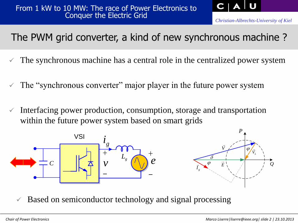
The synchronous machine has a central role in the centralized power system
The “synchronous converter” major player in the future power system
Interfacing power production, consumption, storage and transportation
within the future power system based on smart grids
Based on semiconductor technology and signal processing
From 1 kW to 10 MW: The race of Power Electronics to Conquer the Electric Grid
The PWM grid converter, a kind of new synchronous machine ?

Marco Liserre|[email protected]| slide 3 | 23.10.2013
Christian-Albrechts-University of Kiel
Chair of Power Electronics
vCgL
e
gi
+
-
+
-
vCgL
e
gi
+
-
+
-
P
gI
VLV
E
Q
The PWM grid converter is equivalent to multiple synchronous
machines
The grid converter can control the active and reactive power flow in a
vast frequency range
P
gI
VLV
E
Q
P
gI
VLV
E
Q
1 h n
. . . .
vo
lta
ge
harmonic order
1
h n
PWM carrier and sideband
harmonics
The PWM grid converter frequency behavior
From 1 kW to 10 MW: The race of Power Electronics to Conquer the Electric Grid

Marco Liserre|[email protected]| slide 4 | 23.10.2013
Christian-Albrechts-University of Kiel
Chair of Power Electronics
1. Introduction: from active rectifier to smart grid & renewables
2. Synchronization, harmonic control and resonance damping
3. A new role for the grid-converter: from “multifunctional” to
“universal” converter
4. The last challenge: reliability
5. What’s next ? The Smart Transformer
Outline
From 1 kW to 10 MW: The race of Power Electronics to Conquer the Electric Grid

Marco Liserre|[email protected]| slide 5 | 23.10.2013
Christian-Albrechts-University of Kiel
Chair of Power Electronics
Introduction
From 1 kW to 10 MW: The race of Power Electronics to Conquer the Electric Grid

Marco Liserre|[email protected]| slide 6 | 23.10.2013
Christian-Albrechts-University of Kiel
Chair of Power Electronics
medium and high power systems:
• multi-drive systems
• single drives working frequently in
regenerative operation like cranes and
elevators
PCCVLVGV
ACTIVE
RECTIFIER
p
load
load
From 1 kW to 10 MW: The race of Power Electronics to Conquer the Electric Grid
Active rectifier

Marco Liserre|[email protected]| slide 7 | 23.10.2013
Christian-Albrechts-University of Kiel
Chair of Power Electronics
STATCOMPCCVLV
GV
q
Series and parallel active filters enhance grid power quality compensating
voltage sag, harmonic, reactive power, etc .
From 1 kW to 10 MW: The race of Power Electronics to Conquer the Electric Grid
Power quality conditioners
AC
TIV
E
FIL
TE
R
load
AC
TIV
E
FIL
TE
R
load
LVGV

Marco Liserre|[email protected]| slide 8 | 23.10.2013
Christian-Albrechts-University of Kiel
Chair of Power Electronics
separate control loops active and reactive power
active power control
one station controls the active power
other station controls the DC-link voltage
reactive power control
reactive power or AC side voltage
HVDC based on
PWM grid
converter offers . .
From 1 kW to 10 MW: The race of Power Electronics to Conquer the Electric Grid
HVDC

Marco Liserre|[email protected]| slide 9 | 23.10.2013
Christian-Albrechts-University of Kiel
Chair of Power Electronics
Grid
Phase A
Larm
Larm
#2
n
#1
#2
n
#1
Grid
Phase A
Larm
Larm
#2
n
#1
#2
n
#1Phase A
+Vd
c/2
Larm
Larm
Idc
-Vd
c/2
Vdc
#2
n
#1
#2
n
#1
V∑
C_u
pp
V∑
C_l
ow
S1
S2VC
Sub-module
in
idiff
ip
Vac
VSM
Grid
iac0
Phase B
Phase C
-2.0
0.0
2.0
kA
Ia... Ia... -1.5 Ib... Ic... -2 Ipa Ipb Ipc 1.5 2
-2.0
0.0
2.0
kA
Ia... Ia... -1.5 Ib... Ic... -2 Ipa Ipb Ipc 1.5 2
0
400
800
MW
P Qo P Pdc
-400
0
400
kV
Cc Bb Aa Vabc_t Vabc_g
kA
Simulation results
kA
MW MVAr
kV
P, Q
Arm currents
AC curents
AC voltage
Fault
Limitation
All major companies in the field
Unless properly controlled, the circulating
currents lead to increased losses, higher ratings
of the devices, and may lead to unbalances and
disturbances during transients.
Faults propagation is an issue !
From 1 kW to 10 MW: The race of Power Electronics to Conquer the Electric Grid
MMC-HVDC

Marco Liserre|[email protected]| slide 10 | 23.10.2013
Christian-Albrechts-University of Kiel
Chair of Power Electronics
Source: IET, Aalborg University
Power Flow
Information Flow
Generators
TransmissionNetwork
DistributionNetwork
Customers
Distributed Generation
Green Power
Power Flow
Information Flow
Generators
TransmissionNetwork
DistributionNetwork
Customers
Generators
TransmissionNetwork
DistributionNetwork
Customers
Distributed GenerationDistributed Generation
Green Power
Main issues:
short and long-term expectancy and emergency loadings and reverse power flows in local grids
Hosting capacity of renewables and reliability of the grid
From 1 kW to 10 MW: The race of Power Electronics to Conquer the Electric Grid
Scenario: smart grid and renewables

Marco Liserre|[email protected]| slide 11 | 23.10.2013
Christian-Albrechts-University of Kiel
Chair of Power Electronics
High efficiency (new topologies and new devices)
Transformer-less topologies and Central inverters
Extended lifetime
Reactive power injection (ancillary services)
Inverter market share
From 1 kW to 10 MW: The race of Power Electronics to Conquer the Electric Grid
Power converters for photovoltaic systems

Marco Liserre|[email protected]| slide 12 | 23.10.2013
Christian-Albrechts-University of Kiel
Chair of Power Electronics
Best renewable source for integration in residential buildings
Single-stage transformerless achieves high efficiency
Interaction with the grid (anti-islanding, reactive power injection,
ancillary services)
Vdc
LCL
Filter
FilterDC/AC
Converter
Input power
sourcetransformer & utility
grid
local load
microgrid
PV
Panels
String
Vpv
Ipv
e
PWM
Anti-Islanding
Protections
i
Grid
Synchronization
MPPT Vdc
Control
AC Current
Control
AC Voltage
control for
ancillary functions
From 1 kW to 10 MW: The race of Power Electronics to Conquer the Electric Grid
Small power (<5kW) PVS

Marco Liserre|[email protected]| slide 13 | 23.10.2013
Christian-Albrechts-University of Kiel
Chair of Power Electronics
grid frequency
switching frequency
From 1 kW to 10 MW: The race of Power Electronics to Conquer the Electric Grid
Several new topologies
grid frequency
switching frequency
Vincotech patent: NPC inverter
with decoupled output and
Mosfet’s
S. V. Araùjo, P. Zacharias, R. Mallwitz,
“Highly efficient single-phase
transformerless inverters for grid-connected
photovoltaic systems”, IEEE Transactions on
Industrial Electronics, 57 (9), September
2010.

Marco Liserre|[email protected]| slide 14 | 23.10.2013
Christian-Albrechts-University of Kiel
Chair of Power Electronics
Power quality
From 1 kW to 10 MW: The race of Power Electronics to Conquer the Electric Grid
Leakage current
Size of the filter
Comparison
Power converter rating

Marco Liserre|[email protected]| slide 15 | 23.10.2013
Christian-Albrechts-University of Kiel
Chair of Power Electronics
Transformerless inverter
topologiesEfficiency
Reactive
power
Grid
current
quality
Leakage
current
Size of
the filter
Power
Converter
Rating
PVS
Manufacturers
H5 + + ++ + + ++ SMA
HERIC ++ + + + - ++ Sunways
H6 + + ++ + + + Ingeteam
HB-Neutral Point Clamped ++ + + ++ ++ ++ Danfoss
FB-Zero Voltage Rectifier - + ++ + ++ - -
Araujo ++ - + - -- + -
NPC with decoupled output ++ + - ++ - - -
How the new topologies compare with those on the market ?
Problems arises in the size of the filter, power converter rating and power quality !
From 1 kW to 10 MW: The race of Power Electronics to Conquer the Electric Grid
Comparison

Marco Liserre|[email protected]| slide 16 | 23.10.2013
Christian-Albrechts-University of Kiel
Chair of Power Electronics
Reliability
10-20 MW wind turbines (power converter topologies and generators)
Paralleling of power converters or MV solutions ?
Gearbox
Converter
module 1
Converter
module 2
Converter
module 3
Converter
module 4
Converter
module 5
Converter
module 6
LV/MV
Transformer
Generator
From 1 kW to 10 MW: The race of Power Electronics to Conquer the Electric Grid
Power converters for wind systems

Marco Liserre|[email protected]| slide 17 | 23.10.2013
Christian-Albrechts-University of Kiel
Chair of Power Electronics
Best choice immediately outside residential areas for low impact on
the landscape
High penetration in stand-alone also in combination with other
DER
Power limitation issues, weak grid connection
From 1 kW to 10 MW: The race of Power Electronics to Conquer the Electric Grid
Medium power (<200kW) WTS

Marco Liserre|[email protected]| slide 18 | 23.10.2013
Christian-Albrechts-University of Kiel
Chair of Power Electronics
0 0.05 0.1 0.15 0.2600
650
700
750
time [s]
roto
r spe
ed
[rp
m]
estimated rotor speed
rotor speed
From 1 kW to 10 MW: The race of Power Electronics to Conquer the Electric Grid
Wind turbine systems: small/medium power (<200kW) WTS

Marco Liserre|[email protected]| slide 19 | 23.10.2013
Christian-Albrechts-University of Kiel
Chair of Power Electronics
AC/DC DC/AC
GENERATORE
RETE
ELETTRICA
DSP
Interf
DSP1
LCL
filter
misura
tensione
misura
corrente
MOTORE DI
IMBARDATA
TURBINASKIIP 132GDL120-4DU
misura
tensionemisura
corrente
DSP
Interf
DSP 2
SKIIP 132GD120-3DU
misura
tensione
IRAMS10UP60B
misura
tensione
Interf
chopper
Interf
inverter
Interf
raddrizzatore
From 1 kW to 10 MW: The race of Power Electronics to Conquer the Electric Grid
Wind turbine systems: small/medium power (<200kW) WTS

Marco Liserre|[email protected]| slide 20 | 23.10.2013
Christian-Albrechts-University of Kiel
Chair of Power Electronics
Synchronization,
harmonic control
and resonance damping
From 1 kW to 10 MW: The race of Power Electronics to Conquer the Electric Grid

Marco Liserre|[email protected]| slide 21 | 23.10.2013
Christian-Albrechts-University of Kiel
Chair of Power Electronics
v
kv v
qv
SOGI-QSG
qv
/ dq
PI
v
SRF-PLL
ff
qv
dv
2 2( ) ( )
v k sD s s
v s k s
Synchronization will be crucial for all the grid connected inverters to adapt their behavior in any grid condition
Single PLL based on a second order integrator acting as a sinusoidal follower is the building block of a class of advanced synchronization methods
From 1 kW to 10 MW: The race of Power Electronics to Conquer the Electric Grid
Synchronization: SOGI-PLL

Marco Liserre|[email protected]| slide 22 | 23.10.2013
Christian-Albrechts-University of Kiel
Chair of Power Electronics
v
kv v
qv
SOGI-QSG
qv
/ dq
PI
v
SRF-PLL
ff
qv
dv
From 1 kW to 10 MW: The race of Power Electronics to Conquer the Electric Grid
The origin of SOGI-PLL

Marco Liserre|[email protected]| slide 23 | 23.10.2013
Christian-Albrechts-University of Kiel
Chair of Power Electronics
v
vv
v
qv
v
qv
v
v
v
v
12
12
DSOGI
PNSC
v
v
SOGI-QSG()
e
qv’
v’
w’
v
e
qv’
v’
w’
v
SOGI-QSG()
PI
[Tdq]
qv
dv
v
SRF-PLL ff
2 2
q d qv v v
2
2 22
o
o os s
qv
Detection of the positive and negative sequences will be important during grid-faults
Three-phase system synchronization needs a vectorial approach and a dual PLL
From 1 kW to 10 MW: The race of Power Electronics to Conquer the Electric Grid
Double-SOGI to handle inverse sequence

Marco Liserre|[email protected]| slide 24 | 23.10.2013
Christian-Albrechts-University of Kiel
Chair of Power Electronics
Re 2 2( )P s p i
sC s k k s
s
2 2
3,5,7
( )( )
ih
h
ss k
s h
• Resonant control
• Repetitive control based on DFT 1
0
2 2cos
h
N i
DFT ai k NF z h i N z
N N
1iPResC
resonant controller
i
iG
e
pG*i
i
i
i
iG
e
pG*i i 'i
cG
DFTF FIRk hi
RepF z
From 1 kW to 10 MW: The race of Power Electronics to Conquer the Electric Grid
Harmonic Controllers

Marco Liserre|[email protected]| slide 25 | 23.10.2013
Christian-Albrechts-University of Kiel
Chair of Power Electronics
Hybrid solution: generalized integrator in dq frame
From 1 kW to 10 MW: The race of Power Electronics to Conquer the Electric Grid
Harmonic Controllers

Marco Liserre|[email protected]| slide 26 | 23.10.2013
Christian-Albrechts-University of Kiel
Chair of Power Electronics
Higher power DPGS (like MW WT-systems) switch at low frequency and
resonance frequency needs to be damped selectively
Virtual Losses Harmonic Spectrum
From 1 kW to 10 MW: The race of Power Electronics to Conquer the Electric Grid
Passive damping: selective damping

Marco Liserre|[email protected]| slide 27 | 23.10.2013
Christian-Albrechts-University of Kiel
Chair of Power Electronics
vi
( )dG s ( )fG s( )PIG si
controller
with active
damping
plant
( )ADG s
From 1 kW to 10 MW: The race of Power Electronics to Conquer the Electric Grid
Active damping by means of Notch filter
Converter current
FFT
Self-commissioning

Marco Liserre|[email protected]| slide 28 | 23.10.2013
Christian-Albrechts-University of Kiel
Chair of Power Electronics
A new role
for the grid-converter
From 1 kW to 10 MW: The race of Power Electronics to Conquer the Electric Grid
Marco Liserre|[email protected]| slide 29 | 23.10.2013
Christian-Albrechts-University of Kiel
Chair of Power Electronics
From 1 kW to 10 MW: The race of Power Electronics to Conquer the Electric Grid
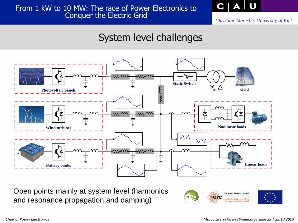
System level challenges
Photovoltaic panels
Wind turbines
Battery banks
Static Switch
Grid
Nonlinear loads
Linear loads
0 0.005 0.01 0.015 0.02-4
-2
0
2
4
0 0.005 0.01 0.015 0.02-1.5
-1
-0.5
0
0.5
1
1.5
0 0.005 0.01 0.015 0.02-1.5
-1
-0.5
0
0.5
1
1.5
0 0.005 0.01 0.015 0.02-1.5
-1
-0.5
0
0.5
1
1.5
0 0.005 0.01 0.015 0.02-1.5
-1
-0.5
0
0.5
1
1.5
0 0.005 0.01 0.015 0.02-1.5
-1
-0.5
0
0.5
1
1.5
0 0.005 0.01 0.015 0.02-1.5
-1
-0.5
0
0.5
1
1.5
Open points mainly at system level (harmonics
and resonance propagation and damping)

Marco Liserre|[email protected]| slide 30 | 23.10.2013
Christian-Albrechts-University of Kiel
Chair of Power Electronics
Results: load support in case of a voltage sag of 0.15 p.u.
Grid voltage E (top): voltage dip of 0.15 p.u., load voltage Vload (middle ), grid current Ig (bottom)
From 1 kW to 10 MW: The race of Power Electronics to Conquer the Electric Grid
Voltage support provided by the DPGS at load level
The grid converter can also maintain the voltage level on a load

Marco Liserre|[email protected]| slide 31 | 23.10.2013
Christian-Albrechts-University of Kiel
Chair of Power Electronics
The reactive power injection by grid-connected systems can enhance the voltage
profile
AC DC
PQ-inverter control
Optimal Reactive Power Control Dynamic
Load-Flow Reduced Network Model
QPV (t)
Distribution Network
MV/LV
PTR (t) VTR(t) θTR(t)
PPV (t) QPV (t) VPV(t) θPV(t)
NON-OPTIMIZED
CONDITION
(PV INVERTER OFF)
OPTIMIZED CONDITION
(PV INVERTER ON)
TRANSFORME
R
SUBSTATION
PCC TRANSFORME
R SUBSTATION PCC
F [HZ] 50 50 50 50
V1 [V] 229 228 230 229
V2 [V] 228 226 228 228
V3 [V] 228 230 228 231
I1 [A] 52.5 1.1 33 3.2
I2 [A] 52 1.1 36.5 2.2
I3 [A] 44 1.1 36.5 0.9
PTOT [W] 19950 730 20200 380
QTOT[VAR] 26550 0 8050 16500
cosφ 0.66 1 0.93 0.02
From 1 kW to 10 MW: The race of Power Electronics to Conquer the Electric Grid
Voltage support provided by the DPGS at EPS area

Marco Liserre|[email protected]| slide 32 | 23.10.2013
Christian-Albrechts-University of Kiel
Chair of Power Electronics
PMSG
chopR
DCu
DCC
Machine-side
converter
Grid-side
converterS
i
Power
filter
1i 2
i
Machine-side
control
Grid-side
controlUnidirectional
Communication
Link
PCCe
State
Load
UWT1
STS
l 1Z liZ
UWTi UWTN
lNZ
Grid
gZ
PCCe
Circuit
BreakerG
e
State manager
PCCe
State
Unidirectional
Communication
Link
DG
units
State
ISLe
From 1 kW to 10 MW: The race of Power Electronics to Conquer the Electric Grid
Universal inverter
The next step is a grid-converter that can work in any condition (grid-connection,
island)

Marco Liserre|[email protected]| slide 33 | 23.10.2013
Christian-Albrechts-University of Kiel
Chair of Power Electronics
Tra
nsfo
rma
ntio
n
ma
trix
TD
ST z
z 1
F z
F z
Pfk
PVk
V
GQ
GQ
GQ
GFQ
GFP
GP
GP
GP
GP
GQ
d
C
d
CV
V
S
S
z 1
T zDfk
ST z
z 1IVk
S
PCC
PCCE
S
S
S
S
PCCE
ST z
z 1PCC
S
PCC
(A)
(B)
(C)
(D)
baseV
base
PLANT
From 1 kW to 10 MW: The race of Power Electronics to Conquer the Electric Grid
Universal Power control
The challenge is to use the same control structure for the different operation modes

Marco Liserre|[email protected]| slide 34 | 23.10.2013
Christian-Albrechts-University of Kiel
Chair of Power Electronics
;
101
102
103
-5
-2.5
0
2.5
5
Frequency (Hz)
Magnitude of the Sensitivity Transfer Function S(Z) (d)
SL
PR+P iC
PR+P i1
PR+PR iC
PR+PR i1
1 5 10 50 100-30
-20
-10
0
10
20
Frequency (Hz)
a) |Z0| (d)
1 5 10 50 100
-300
-200
-100
0
Frequency (Hz)
b) Angle of Z0 (º deg)
SL
PR+P iC
PR+P i1
PR+PR iC
PR+PR i1
0 0.2 0.4 0.6 0.8 1
-0.6
-0.4
-0.2
0
0.2
0.4
0.6
0.8
Imag
inar
y ax
is
Real axis
24kW
24kW
6kW
6kW
24kW
24kW
6kW6kW
SL
PR+P iC
PR+P i1
PR+PR iC
PR+PR i1
-1 -0.8 -0.6 -0.4 -0.2 0 0.2 0.4 0.6
-1
-0.8
-0.6
-0.4
-0.2
0
0.2
0.4
0.6
0.8
1
d1
d2
d3
d4
d5
Re[L(z)]
Im[L
(z)]
SL
PR+P iC
PR+P i1
PR+PR iC
PR+PR i1
Grid-connected
Island mode
From 1 kW to 10 MW: The race of Power Electronics to Conquer the Electric Grid
Universal Power control

Marco Liserre|[email protected]| slide 35 | 23.10.2013
Christian-Albrechts-University of Kiel
Chair of Power Electronics
The kinetic storage of the UWT together with a suitable control strategy can be used to operate the UWT in island mode for a certain time without any additional storage
Statistical assessment of the power reliability improvement shall be done by means of SIER
Wind
turbineRotor
DC-link
capacitors
Aerodynamic
losses
Mechanical
losses
Generator
and switching
losses
Switching and
filter losses
Injected
power
Generated
powerWind
Power
Kinetic stored
energy
MPPT LOSSES
LOADb )
)
P
a P P
WT MPPT
WTb
) P P
) P
a
WT LOAD LOSSESb )
a )
P ( P P )
0
a )Grid connec
b ) Is
te
d
d
lan
Chopper
losses
0 10 20 30 40 500
5
10
15
20
Power (kW)
Pro
bab
ilit
y (%
)
Generation
Load P1
=15 kW
Load P2
=20 kW
Load P3
=25 kW
Load P4
=30 kW
Load P5
=35 kW
Load P6
=40 kW
From 1 kW to 10 MW: The race of Power Electronics to Conquer the Electric Grid
Universal operation without storage

Marco Liserre|[email protected]| slide 36 | 23.10.2013
Christian-Albrechts-University of Kiel
Chair of Power Electronics
UWT can be used to reduce the average interruption time
The reduction in the average interruption time obtained by means of the Universal Operation is quite remarkable, being at least 22.27 % and 60.5 % in the best case
'Tμ (s)
Average Load Consumption
P1μ P2μ P3μ P4μ P5μ P6μ
Avera
ge
Inte
rru
pti
on
Du
rati
on
T 1μ 3.95 4.64 5.26 5.69 6.19 6.52
T 2μ 62.50 71-02 78.32 83.37 87.82 91.59
T 3μ 321.83 364.82 401.08 427.83 446.63 466.39
From 1 kW to 10 MW: The race of Power Electronics to Conquer the Electric Grid
Calculation of reduction of interruption time

Marco Liserre|[email protected]| slide 37 | 23.10.2013
Christian-Albrechts-University of Kiel
Chair of Power Electronics
The last challenge
From 1 kW to 10 MW: The race of Power Electronics to Conquer the Electric Grid
Marco Liserre|[email protected]| slide 38 | 23.10.2013
Christian-Albrechts-University of Kiel
Chair of Power Electronics
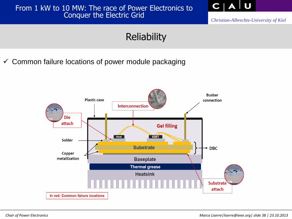
Common failure locations of power module packaging
From 1 kW to 10 MW: The race of Power Electronics to Conquer the Electric Grid
Reliability

Marco Liserre|[email protected]| slide 39 | 23.10.2013
Christian-Albrechts-University of Kiel
Chair of Power Electronics
The killer is the temperature swing because of different thermal
coefficients
T1
D1
T2
D2
T3
D3
T4
D4
D5
D6
Time(s)
Ju
nctio
n te
mp
era
ture
(℃
)
Dnpc
T1
T2 D1
D2
Time (s)
Temperature vs reliability
From 1 kW to 10 MW: The race of Power Electronics to Conquer the Electric Grid

Marco Liserre|[email protected]| slide 40 | 23.10.2013
Christian-Albrechts-University of Kiel
Chair of Power Electronics
Thermal stress is determined by many factors & time constants.
Mechanical ElectricalEnvironmental
sec
Medium term
(Mechanical control)
Long term
(Ambient change)
Short term
(Converter control)
houryear millisec
1 year, 3 hours step 3 hours, 1 second step 0.2 second, 0. 01 millsec step
From 1 kW to 10 MW: The race of Power Electronics to Conquer the Electric Grid
Thermal stress of IGBT in wind power converter

Marco Liserre|[email protected]| slide 41 | 23.10.2013
Christian-Albrechts-University of Kiel
Chair of Power Electronics
Co
nsu
me
d B
10
life
tim
e (
%)
Wind speed (m/s)C
on
su
me
d B
10
life
tim
e (
%)
Consumed life time vs. different wind speeds.
Consumed life time vs. different failure mechanisms.
From 1 kW to 10 MW: The race of Power Electronics to Conquer the Electric Grid
Lifetime of IGBT by medium term thermal loading
Marco Liserre|[email protected]| slide 42 | 23.10.2013
Christian-Albrechts-University of Kiel
Chair of Power Electronics
0
25
75
90
100
150 500 750 1000 1500
Voltage(%)
Time (ms)
DenmarkSpain
Germany
US
Keep connected
above the curves
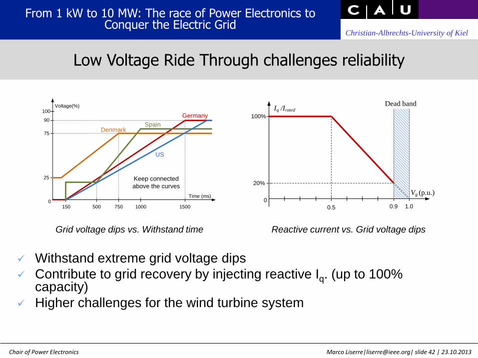
Grid voltage dips vs. Withstand time
100%
Iq /Irated
Vg (p.u.)
0.5
0
Dead band
0.9 1.0
20%
Reactive current vs. Grid voltage dips
Withstand extreme grid voltage dips
Contribute to grid recovery by injecting reactive Iq. (up to 100% capacity)
Higher challenges for the wind turbine system
From 1 kW to 10 MW: The race of Power Electronics to Conquer the Electric Grid
Low Voltage Ride Through challenges reliability

Marco Liserre|[email protected]| slide 43 | 23.10.2013
Christian-Albrechts-University of Kiel
Chair of Power Electronics
0
500
1000
1500
2000
2500
3000
3500
4000
4500
Tout Dout Tin Din Dnpc
Normal
phase B
phase A
phase C
Lo
ss (
W)
0
500
1000
1500
2000
2500
3000
3500
4000
4500
Tout Dout Tin Din Dnpc
Normal
phase C
phase A
phase B
Lo
ss (
W)
0
500
1000
1500
2000
2500
3000
3500
4000
4500
Tout Dout Tin Din Dnpc
Normal
phase A
phase B
phase C
Lo
ss (
W)
1 phase grounded 2 phase connected
3 phase grounded
(D1=0 p.u., vw=12 m/s, no negative seq. I, 110 % DC bus)
LVRT operations impose the diodes and inner switches with significant larger losses than the most stressed normal operation.
Loss distribution among the three phases is asymmetrical under the unbalance faults.
From 1 kW to 10 MW: The race of Power Electronics to Conquer the Electric Grid
Loss distribution

Marco Liserre|[email protected]| slide 44 | 23.10.2013
Christian-Albrechts-University of Kiel
Chair of Power Electronics
Different sensors can be employed:
ambient sensors (temperature, humidity and pollution);
internal sensors (module temperature, vibration, electric parameters)
Data acquisition is very important: there are issues related to the amount of data that is possible to store and how to use those data.
Two main goals: a proactive maintenance plan or proactive control schemes
Wind power converters under operation
Wind speed
Sensors
Temperature
Sensors
Humidity
Sensors
Voltage
Sensor
s
Current
Sensors
Vibration
Sensors
Wireless Wiredor
Communication
Co
ntr
ol
On-line remaining life
prediction
Condition monitoring
Failure cause and location
analysis
Proactive control scheme
Workstation
From 1 kW to 10 MW: The race of Power Electronics to Conquer the Electric Grid
Real time monitoring

Marco Liserre|[email protected]| slide 45 | 23.10.2013
Christian-Albrechts-University of Kiel
Chair of Power Electronics
The reactive power changes the losses distribution among the power devices hence can be used to control the thermal cycling and the peak temperature of some of them
Many new WTS topologies are based on a modular design that allows circulating reactive power among them
...
...Multi winding
generator
To grid
AC
DC
DC
AC
AC
DC
DC
AC
...
From 1 kW to 10 MW: The race of Power Electronics to Conquer the Electric Grid
Active Thermal control by means of reactive power
Marco Liserre|[email protected]| slide 46 | 23.10.2013
Christian-Albrechts-University of Kiel
Chair of Power Electronics
Generator
AC
DC
DC
ACFilter FilterGear
Full scale converter
PV PV PV PV PV
Capacitor for Local
Reactive Power
Compensation STS
1000kVA
20kV
Grid
0.4kV
1 2 3 4 n
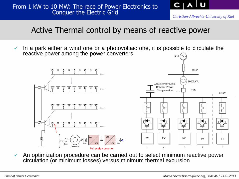
In a park either a wind one or a photovoltaic one, it is possible to circulate the reactive power among the power converters
An optimization procedure can be carried out to select minimum reactive power circulation (or minimum losses) versus minimum thermal excursion
From 1 kW to 10 MW: The race of Power Electronics to Conquer the Electric Grid
Active Thermal control by means of reactive power
Marco Liserre|[email protected]| slide 47 | 23.10.2013
Christian-Albrechts-University of Kiel
Chair of Power Electronics
Reactive power (p.u.)
Ph
ase
cu
rre
nt a
mp
litu
de
Ig
(p.u
.)
8 m/s
10 m/s
12 m/s
Underexcited Overexcited
Reactive power (p.u.)
Ph
ase
an
gle
Ig
- U
c (
de
gre
e)
8 m/s
10 m/s
12 m/s
Underexcited Overexcited
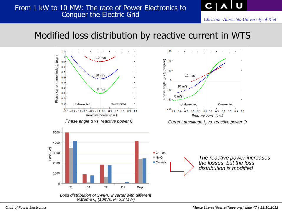
Current amplitude Ig vs. reactive power Q
Phase angle α vs. reactive power Q
0
1000
2000
3000
4000
5000
T1 D1 T2 D2 Dnpc
Q- max
No Q
Q+ max
Lo
ss (
W)
Loss distribution of 3-NPC inverter with different extreme Q (10m/s, P=6.3 MW)
The reactive power increases the losses, but the loss distribution is modified
From 1 kW to 10 MW: The race of Power Electronics to Conquer the Electric Grid
Modified loss distribution by reactive current in WTS

Marco Liserre|[email protected]| slide 48 | 23.10.2013
Christian-Albrechts-University of Kiel
Chair of Power Electronics
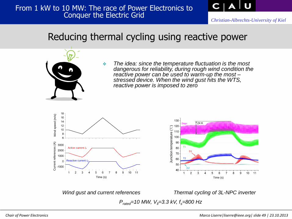
Wind gust from 10 m/s to 8m/s then to16 m/s in 10 seconds
Junction temperature in clamping diode Dnpc fluctuates up to 43K
Large ΔTj results in reduced life time of devices
Cu
rre
nt re
fere
nce
s (
A)
Active current IP
Reactive current IQ
Time (s)
Win
d s
pe
ed
(m
/s)
Ju
nctio
n te
mp
era
ture
(℃
)
T1
T2 D1
D2
Time (s)
Dnpc43 K
Thermal cycling of 3L-NPC inverter Wind gust and current references
Prated=10 MW, Vll=3.3 kV, fs=800 Hz
From 1 kW to 10 MW: The race of Power Electronics to Conquer the Electric Grid
Thermal cycling during a wind gust
Marco Liserre|[email protected]| slide 49 | 23.10.2013
Christian-Albrechts-University of Kiel
Chair of Power Electronics
The idea: since the temperature fluctuation is the most dangerous for reliability, during rough wind condition the reactive power can be used to warm-up the most –stressed device. When the wind gust hits the WTS, reactive power is imposed to zero
Thermal cycling of 3L-NPC inverter Wind gust and current references
Prated=10 MW, Vll=3.3 kV, fs=800 Hz
Cu
rre
nt re
fere
nce
s (
A)
Active current IP
Reactive current IQ
Time (s)
Win
d s
pe
ed
(m
/s)
Ju
nctio
n te
mp
era
ture
(℃
)
T1
T2
D1
D2
Time (s)
Dnpc 24 K
From 1 kW to 10 MW: The race of Power Electronics to Conquer the Electric Grid
Reducing thermal cycling using reactive power

Marco Liserre|[email protected]| slide 50 | 23.10.2013
Christian-Albrechts-University of Kiel
Chair of Power Electronics
Q is circulated among paralleled converters
Larger Q range can be achieved
Grid codes can be still satisfied
T1
Dnpc1
D1
T2
D2 Grid
Converter 2 (Overexcited operation)
...
Converter N
P1
P2
Underexcited
-Q
Dnpc2
T3
D3
D4T4
Overexcited
+Q
Converter 1 (Underexcited operation)
T1
Dnpc1
D1
T2
D2
Grid
Converter 2 (Overexcited operation)
...
Converter N
P1
P2
-Q
Dnpc2
T3
D3
D4T4
+Q
Converter 1 (Underexcited operation)
Parallel converters in single wind turbine system Parallel converters in wind park
From 1 kW to 10 MW: The race of Power Electronics to Conquer the Electric Grid
Idea to extend to Q range

Marco Liserre|[email protected]| slide 51 | 23.10.2013
Christian-Albrechts-University of Kiel
Chair of Power Electronics
Cu
rre
nt re
fere
nce
s (
A)
Active current IP
Reactive current IQ
Time (s)
Win
d s
pe
ed
(m
/s)
Cu
rre
nt re
fere
nce
s (
A)
Active current IP
Reactive current IQ
Time (s)
Win
d s
pe
ed
(m
/s)
Cu
rre
nt re
fere
nce
s (
A)
Active current IP
Reactive current IQ
Time (s)
Win
d s
pe
ed
(m
/s)
Ju
nctio
n te
mp
era
ture
(℃
)
T1
T2 D1
D2
Time (s)
Dnpc43 K
Ju
nctio
n te
mp
era
ture
(℃
)
T1
T2
D1
D2
Time (s)
Dnpc 24 K
Ju
nctio
n te
mp
era
ture
(℃
)
T1
T2
D1
D2
Time (s)
Dnpc
39 K
Without reactive power With underexcited reactive power With overexcited reactive power
Thermal fluctuation during wind gust can be improved
Thermal fluctuation in compensating converter are not significantly enlarge
From 1 kW to 10 MW: The race of Power Electronics to Conquer the Electric Grid
Parallel operation of WTS

Marco Liserre|[email protected]| slide 52 | 23.10.2013
Christian-Albrechts-University of Kiel
Chair of Power Electronics
What’s next ?
From 1 kW to 10 MW: The race of Power Electronics to Conquer the Electric Grid

Marco Liserre|[email protected]| slide 53 | 23.10.2013
Christian-Albrechts-University of Kiel
Chair of Power Electronics
From 1 kW to 10 MW: The race of Power Electronics to Conquer the Electric Grid
Critical issues of the future electric grid

Marco Liserre|[email protected]| slide 54 | 23.10.2013
Christian-Albrechts-University of Kiel
Chair of Power Electronics
From 1 kW to 10 MW: The race of Power Electronics to Conquer the Electric Grid
A possible solution: the Smart Transformer

Marco Liserre|[email protected]| slide 55 | 23.10.2013
Christian-Albrechts-University of Kiel
Chair of Power Electronics
- Power quality enhancement: disturbance isolation, harmonics and transients
- DC-connectivity: future MVDC, low voltage DC grids and renewable
energy
- Fault reclosing coordination
- Energy storage: Electric vehicle batteries (challenges and opportunities)
From 1 kW to 10 MW: The race of Power Electronics to Conquer the Electric Grid
Capabilities of the Smart Transformer

Marco Liserre|[email protected]| slide 56 | 23.10.2013
Christian-Albrechts-University of Kiel
Chair of Power Electronics
One stage (AC-MV/AC-LV)/ Two stage (AC-MV/DC-MV /AC-LV)
Reduced component counts
Does not allow integration of either MV/LV DC network
disturbances on one side may also affect the other side
Three Stage (AC-MV/DC-MV/DC-LV/AC-LV)
DC-links on both sides and performing three stages of conversion
Allows direct integration of renewable DC sources
Modularity
From 1 kW to 10 MW: The race of Power Electronics to Conquer the Electric Grid
ST Architecture

Marco Liserre|[email protected]| slide 57 | 23.10.2013
Christian-Albrechts-University of Kiel
Chair of Power Electronics
From 1 kW to 10 MW: The race of Power Electronics to Conquer the Electric Grid
Several architectures
1
2
4
3
5

Marco Liserre|[email protected]| slide 58 | 23.10.2013
Christian-Albrechts-University of Kiel
Chair of Power Electronics
- Cascaded H-bridge seems to be the best solution but it does not allow MVDC connectivity
- MVDC connectivity is at the expense of efficiency
From 1 kW to 10 MW: The race of Power Electronics to Conquer the Electric Grid
Comparison
Marco Liserre|[email protected]| slide 59 | 23.10.2013
Christian-Albrechts-University of Kiel
Chair of Power Electronics
Power electronics converters connected to the grid have unexplored opportunities (e.g. multifrequencies)
Many applications such as PVS, WTS or HVDC still have had recent innovation both in the adopted power converter topologies and their control
Harmonic/resonance propagation/damping at system level and universal operation are still open points
Design and Control for reliability of power electronics systems is important for the electric grid
The Smart Transformer is the next big thing !
From 1 kW to 10 MW: The race of Power Electronics to Conquer the Electric Grid
Conclusions

Marco Liserre|[email protected]| slide 60 | 23.10.2013
Christian-Albrechts-University of Kiel
Chair of Power Electronics
The work on power converter and the grid has been developed in the last 13 years within or in cooperation with
Politecnico di Bari (Italy)
Aalborg University (Denmark)
Alcalá University (Spain)
From 1 kW to 10 MW: The race of Power Electronics to Conquer the Electric Grid
Acknowledgement