Copper Mountain 200/150/OnPrem2400 DSL...
41
Copper Mountain 200/150/OnPrem2400 DSL SPECTRUM Enterprise Manager Device Management Supports Management Module SM-CPM1000 Titlepae Titlepae Titlepae Titlepae
Transcript of Copper Mountain 200/150/OnPrem2400 DSL...
Copper Mountain 200/150/OnPrem2400 DSL
SPECTRUM Enterprise ManagerDevice Management
Supports Management Module SM-CPM1000
TitlepaeTitlepaeTitlepaeTitlepae

D e v i c e M a n a g e m e n t Page 2 C o p p e r M o u n t a i n 2 0 0 / 1 5 0 / O n P r e m 2 4 0 0
NoticeAprisma Management Technologies, Inc. (Aprisma), reserves the right to makechanges in specifications and other information contained in this document withoutprior notice. The reader should in all cases consult Aprisma to determine whetherany such changes have been made.
The hardware, firmware, or software described in this manual is subject to changewithout notice.
IN NO EVENT SHALL APRISMA, ITS EMPLOYEES, OFFICERS, DIRECTORS,AGENTS, OR AFFILIATES BE LIABLE FOR ANY INCIDENTAL, INDIRECT,SPECIAL, OR CONSEQUENTIAL DAMAGES WHATSOEVER (INCLUDING BUTNOT LIMITED TO LOST PROFITS) ARISING OUT OF OR RELATED TO THISMANUAL OR THE INFORMATION CONTAINED IN IT, EVEN IF APRISMA HASBEEN ADVISED OF, KNOWN, OR SHOULD HAVE KNOWN, THE POSSIBILITYOF SUCH DAMAGES.
Copyright © April 2001 by Aprisma Management Technologies. All rights reserved.
Printed in the United States of America.
Order Number: 9035007-01
Aprisma Management Technologies, Inc.121 Technology DriveDurham NH 03824
SPECTRUM, the SPECTRUM IMT/VNM logo, DCM, IMT, and VNM are registeredtrademarks, and SpectroGRAPH , SpectroSERVER , Inductive ModelingTechnology , Device Communications Manager , and Virtual Network Machineare trademarks of Aprisma or its affiliates.
Ethernet is a trademark of Xerox Corporation.
Copper Edge is a Trademark of Copper Mountian Technologies
Virus DisclaimerAprisma makes no representations or warranties to the effect that the LicensedSoftware is virus-free.
Aprisma has tested its software with current virus checking technologies. However,because no anti-virus system is 100% reliable, we strongly caution you to writeprotect and then verify that the Licensed Software, prior to installing it, is virus-freewith an anti-virus system in which you have confidence.
Restricted Rights Notice(Applicable to licenses to the United States Government only.)
1. Use, duplication, or disclosure by the Government is subject to restrictions asset forth in subparagraph (c) (1) (ii) of the Rights in Technical Data andComputer Software clause at DFARS 252.227-7013.
Aprisma Management Technologies, Inc., 121 Technology Drive NH 03824
2. (a) This computer software is submitted with restricted rights. It may not beused, reproduced, or disclosed by the Government except as provided inparagraph (b) of this Notice or as otherwise expressly stated in the contract.
(b) This computer software may be:
(1) Used or copied for use in or with the computer or computers for whichit was acquired, including use at any Government installation to whichsuch computer or computers may be transferred;
(2) Used or copied for use in a backup computer if any computer for whichit was acquired is inoperative;
(3) Reproduced for archival or backup purposes;
(4) Modified, adapted, or combined with other computer software, providedthat the modified, combined, or adapted portions of the derivativesoftware incorporating restricted computer software are made subjectto the same restricted rights;
(5) Disclosed to and reproduced for use by support service contractors inaccordance with subparagraphs (b) (1) through (4) of this clause,provided the Government makes such disclosure or reproductionsubject to these restricted rights; and
(6) Used or copied for use in or transferred to a replacement computer.
(c) Notwithstanding the foregoing, if this computer software is publishedcopyrighted computer software, it is licensed to the Government, withoutdisclosure prohibitions, with the minimum rights set forth in paragraph (b) ofthis clause.
(d) Any other rights or limitations regarding the use, duplication, or disclosureof this computer software are to be expressly stated in, or incorporated in,the contract.
(e) This Notice shall be marked on any reproduction of this computer software, inwhole or in part.
D e n 2 0 0 / 1 5 0 / O n P r e m 2 4 0 0
IN
PRST
TA
DE
I
DE
14
.............................................14
.............................................15
.............................................15tions .....................................16.............................................16able......................................16.............................................18.............................................19.............................................20SLLineApp) ........................21
.............................................21iew .......................................22le View ................................22ance Table View..................23iew .......................................23le View ................................24ance Table View..................25.............................................25
26
.............................................27
28
............................................28View .....................................29
v i c e M a n a g e m e n t Page 3 C o p p e r M o u n t a i
ContentsTRODUCTION 5
urpose and Scope ........................................................5equired Reading ...........................................................5upported Devices..........................................................6he SPECTRUM Model ..................................................6
Additional (Optional) Menus:....................................7
SKS 8
Application Information (examine) ........................8Device (configure) ................................................8Device Performance (monitor) .............................8Launchable Applications ......................................8Model Information (examine)................................8Model Redundancy (configure) ............................8Port Configuration (examine/modify) ....................8A Port (examine/enable/disable) ..........................8Traps (view/monitor).............................................8
VICE VIEWS 9
nterface Icons ..............................................................10Interface Icon Subviews Menu Options .....................11Interface Status View.................................................12Secondary Address Panel .........................................12
VICE TOPOLOGY VIEWS 13
APPLICATION VIEWS
Main Application View......Supported Applications ....
Common Applications ..Device-Specific Applica
Ds3App1407 Application .DS3/E3 Configuration TDS3/E3 Current Table ..DS3/E3 Interval Table ..DS3/E3 Total Table ......
ADSL Line Application (ADLine Table.....................ATUC Physical Table VATUC Performance TabATUC Channel PerformATUR Physical Table VATUR Performance TabATUR Channel PerformConfiguration View .......
PERFORMANCE VIEWS
Performance View............
CONFIGURATION VIEWS
Device Configuration ViewInterface Configuration
C o C o n t e n t s
D e n 2 0 0 / 1 5 0 / O n P r e m 2 4 0 0
TR
T
TR
T
CO
MO
IN
n t e n t s
v i c e M a n a g e m e n t Page 4 C o p p e r M o u n t a i
AP ALARM COUNTER VIEW 30
rap Alarm Counter Attributes ......................................31
AP EVENT LOG VIEW 32
rap Event Table ..........................................................33
PPER VIEW/COPPER ELEMENT MANAGER 37
Instructions.............................................................37
DEL INFORMATION VIEWS 39
DEX 40

S P n 2 0 0 / 1 5 0 / O n P r e m 2 4 0 0
er Mountain devices.
Thdoco
••••
PUsComdoviecodeSP
Onmdoab
c SPECTRUM functionality ues, refer to the topics Reading.
ingtion effectively, you must ormation covered by the e documentation topics
h SPECTRUM for Operators
h SPECTRUM for
ur Network with SPECTRUM
le Software Release Notice
E C T R U M E n t e r p r i s e M a n a g e r 5 C o p p e r M o u n t a i
Introduction
This section introduces the SPECTRUM Device Management documentation for Copp
is introduction to the Device Management cumentation for Copper Mountain devices ntains the following information:
Purpose and ScopeRequired ReadingSupported Devices (Page 6)The SPECTRUM Model (Page 6)
urpose and Scopee this documentation as a guide for managing pper Mountain devices with the SPECTRUM
anagement module SM-CPM1000. The cumentation describes the icons, menus, and ws that enable you to remotely monitor, nfigure, and troubleshoot Copper Mountain vices through software models in your ECTRUM database.
ly information specific to the supported anagement module is included under this cumentation topic. For general information out device management using SPECTRUM and
for explanations of basiand navigation techniqlisted under Required
Required ReadTo use this documentabe familiar with the infother SPECTRUM onlinlisted below.
• Getting Started wit
• Getting Started witAdministrators
• How To Manage Yo
• SPECTRUM Views
• SPECTRUM Menus
• SPECTRUM Icons
• Management Modu
I n S u p p o r t e d D e v i c e s
S P n 2 0 0 / 1 5 0 / O n P r e m 2 4 0 0
SThCPdide
•
•
•
M Modele Copper Mountain are dgeDSL_V, OnPrem2400.
creation of Device icons per Mountain devices and represent their supported e icons contain double- access to Icon Subviews form device management listed in Tasks on Page 8.
appearance of the Device pending on the kind of view
nd Large Device Icons
Model Name
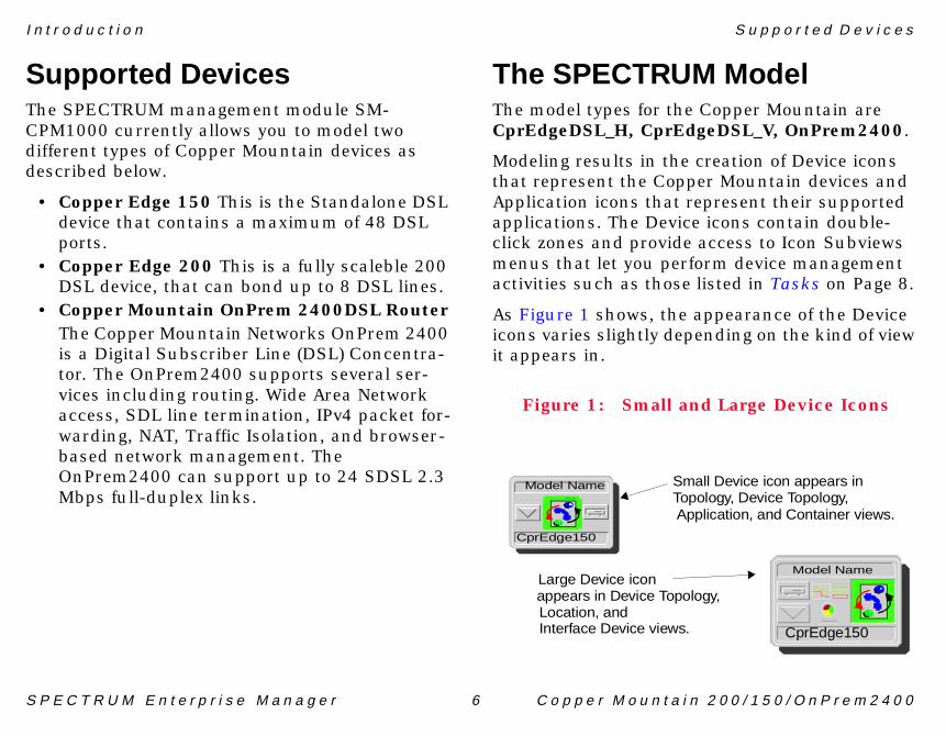
all Device icon appears in
CprEdge150
pology, Device Topology,
logy,
.
pplication, and Container views.
t r o d u c t i o n
E C T R U M E n t e r p r i s e M a n a g e r 6 C o p p e r M o u n t a i
upported Devicese SPECTRUM management module SM-M1000 currently allows you to model two
fferent types of Copper Mountain devices as scribed below.
Copper Edge 150 This is the Standalone DSL device that contains a maximum of 48 DSL ports.Copper Edge 200 This is a fully scaleble 200 DSL device, that can bond up to 8 DSL lines. Copper Mountain OnPrem 2400DSL Router The Copper Mountain Networks OnPrem 2400 is a Digital Subscriber Line (DSL) Concentra-tor. The OnPrem2400 supports several ser-vices including routing. Wide Area Network access, SDL line termination, IPv4 packet for-warding, NAT, Traffic Isolation, and browser-based network management. The OnPrem2400 can support up to 24 SDSL 2.3 Mbps full-duplex links.
The SPECTRUThe model types for thCprEdgeDSL_H, CprE
Modeling results in thethat represent the CopApplication icons that applications. The Devicclick zones and providemenus that let you peractivities such as those
As Figure 1 shows, theicons varies slightly deit appears in.
Figure 1: Small a
Large Device icon
Model Name
CprEdge150
SmTo
appears in Device TopoLocation, andInterface Device views
A
I n T h e S P E C T R U M M o d e l
S P n 2 0 0 / 1 5 0 / O n P r e m 2 4 0 0
Thmvie
••••••••
Ad•
t r o d u c t i o n
E C T R U M E n t e r p r i s e M a n a g e r 7 C o p p e r M o u n t a i
e rest of the documentation for this anagement module is organized according to w type, as follows.
Device Views (Page 9)Device Topology Views (Page 13)Application Views (Page 14)Performance Views (Page 26)Configuration Views (Page 28)Trap Alarm Counter View (Page 30)Trap Event Log View (Page 32)Model Information Views (Page 39)
ditional (Optional) Menus:Copper View/Copper Element Manager on Page 37
S P n 2 0 0 / 1 5 0 / O n P r e m 2 4 0 0
tions of the views and/or
Ap•
De•
De•
La•
M•
M•
Po•
n View (Page 28)
le/disable)w (Page 12)
r View (Page 30)w (Page 32)
E C T R U M E n t e r p r i s e M a n a g e r 8 C o p p e r M o u n t a i
Tasks
This section lists device management tasks alphabetically and provides links to descriptables used to perform the task.
plication Information (examine)Application Views (Page 14)
vice (configure)Configuration Views (Page 28)
vice Performance (monitor)Device Views (Page 9)
unchable ApplicationsCopper View/Copper Element Manager (Page 37)
odel Information (examine)Model Information Views (Page 39)
odel Redundancy (configure)Device Configuration View (Page 28)
rt Configuration (examine/modify)Interface Icons (Page 10)
• Device Configuratio
A Port (examine/enab• Interface Status Vie
Traps (view/monitor)• Trap Alarm Counte• Trap Event Log Vie
S P n 2 0 0 / 1 5 0 / O n P r e m 2 4 0 0
Mountain devices in
ThremprinneInThicoan
rface Device View
raph: Router Device
System Up TimeManufacturerDevice TypeSerial Number
ddress
ation
scription
Addr
Help
E C T R U M E n t e r p r i s e M a n a g e r 9 C o p p e r M o u n t a i
Device Views
This section describes the Device views and subviews available for models of CopperSPECTRUM.
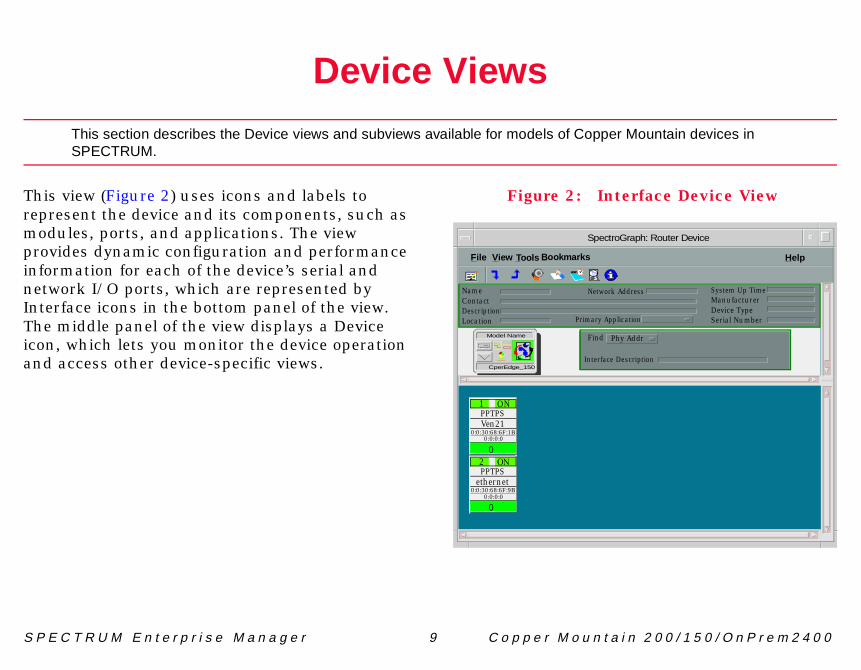
is view (Figure 2) uses icons and labels to present the device and its components, such as odules, ports, and applications. The view ovides dynamic configuration and performance formation for each of the device’s serial and twork I/O ports, which are represented by terface icons in the bottom panel of the view. e middle panel of the view displays a Device n, which lets you monitor the device operation d access other device-specific views.
Figure 2: Inte
SpectroG
File View
NameContactDescriptionLocation
Network A
Primary Applic
Interface De
Find PhyModel Name
CperEdge_150
PPTPSVen21
0
1 ON
0:0:30:68:6F:1B0:0:0:0
PPTPSethernet
0
2 ÿþ
0:0:30:68:6F:9B0:0:0:0
Tools Bookmarks
D e I n t e r f a c e I c o n s
S P n 2 0 0 / 1 5 0 / O n P r e m 2 4 0 0
InFifroindoth
interface number.
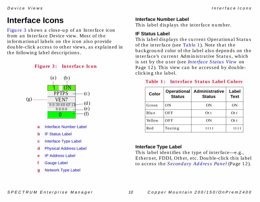
current Operational Status ble 1). Note that the e label also depends on the inistrative Status, which
Interface Status View on be accessed by double-
type of interface—e.g., etc. Double-click this label y Address Panel (Page 12).
e Status Label Colors
AdministrativeStatus
LabelText
ÿþ ÿþ
ÿ�� ÿ��
ÿþ ÿ��
���� ����
v i c e V i e w s
E C T R U M E n t e r p r i s e M a n a g e r 10 C o p p e r M o u n t a i
terface Iconsgure 3 shows a close-up of an Interface icon m an Interface Device view. Most of the
formational labels on the icon also provide uble-click access to other views, as explained in e following label descriptions.
Figure 3: Interface Icon
Interface Number LabelThis label displays the
IF Status LabelThis label displays the of the interface (see Tabackground color of thinterface’s current Admis set by the user (see Page 12). This view canclicking the label.
Interface Type LabelThis label identifies theEthernet, FDDI, Other,to access the Secondar
PPTPSVEN7
0
1 ON
0:0:30:68:6F:1B0:0:0:0
a Interface Number Label
b IF Status Label
c Interface Type Label
d Physical Address Label
e IP Address Label
f Gauge Label
g Network Type Label
(a) (b)
(c)
(d)(e)(f)
(g)
Table 1: Interfac
ColorOperational
Status
Green ON
Blue OFF
Yellow OFF
Red Testing
D e I n t e r f a c e I c o n s
S P n 2 0 0 / 1 5 0 / O n P r e m 2 4 0 0
PhThthInrephbecoTrprcota
IPThinSeyoin
GaThstapaSPinCo
type of network the o. Double-click the label to ation view for the interface.
bviews Menu
ubviews menu options ce icon.
e Icon Subviews Menu
Opens the...
face Detail view, which displays et, Error, and Discard kdown pie charts.
face Status View (Page 12)
e 28)
l Information view for the ted interface (see Model mation Views on Page 39)
face Address Translation Table which shows the Physical and ork address for each interface.
ndary Address Panel (Page 12)
v i c e V i e w s
E C T R U M E n t e r p r i s e M a n a g e r 11 C o p p e r M o u n t a i
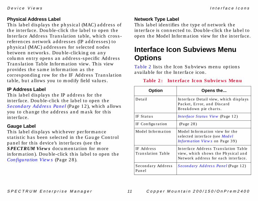
ysical Address Labelis label displays the physical (MAC) address of e interface. Double-click the label to open the terface Address Translation table, which cross-ferences network addresses (IP addresses) to ysical (MAC) addresses for selected nodes tween networks. Double-clicking on any lumn entry opens an address-specific Address anslation Table Information view. This view ovides the same information as the rresponding row for the IF Address Translation ble, but allows you to modify field values.
Address Labelis label displays the IP address for the
terface. Double-click the label to open the condary Address Panel (Page 12), which allows u to change the address and mask for this terface.
uge Labelis label displays whichever performance tistic has been selected in the Gauge Control nel for this device’s interfaces (see the ECTRUM Views documentation for more
formation). Double-click this label to open the nfiguration Views (Page 28).
Network Type LabelThis label identifies theinterface is connected topen the Model Inform
Interface Icon SuOptionsTable 2 lists the Icon Savailable for the Interfa
Table 2: Interfac
Option
Detail InterPackBrea
IF Status Inter
IF Configuration (Pag
Model Information ModeselecInfor
IF Address Translation Table
Interview,Netw
Secondary Address Panel
Seco

D e I n t e r f a c e I c o n s
S P n 2 0 0 / 1 5 0 / O n P r e m 2 4 0 0
InAcico
Thstadi
OpThTe
AdThopTe
SAcicoAd
able of IP addresses and he Address Translation ’s firmware. You can ress displayed in the IP
ing an entry from the table ing the Update button.
Th
v i c e V i e w s
E C T R U M E n t e r p r i s e M a n a g e r 12 C o p p e r M o u n t a i
terface Status Viewcess: From the Icon Subviews menu for the Interfacen in the Interface Device view, select IF Status .
is view provides information on the operational tus of the interface and allows you to enable or
sable the port.
erational Statuse current state of the interface (ON, OFF, or sting ).
ministrative Statusis button allows you to select the desired erational state of the interface (ON, OFF, or sting ).
econdary Address Panelcess: From the Icon Subviews menu for the Interfacen in the Interface Device view, select Secondarydress Panel .
This panel provides a tmasks obtained from ttable within the devicechange the current addAddress field by selectin this panel and click
resholds Interface Threshold view, which allows you to set the on/off alarm thresholds for load, packet rate, error rate, and% discarded.
Table 2: Interface Icon Subviews Menu
Option Opens the...

S P n 2 0 0 / 1 5 0 / O n P r e m 2 4 0 0
els of Copper Mountain
AcMo
Thviethprasthinabrede
e Device Topology View
modem
Router Device
Model Name
Model Type
Help
ame
Type
modem
etherne
t
undefined
undefined
undefined
0 3 Dwn 0 6 Dwn 0
E C T R U M E n t e r p r i s e M a n a g e r 13 C o p p e r M o u n t a i
Device Topology Views
This section provides brief descriptions of the Device Topology views available for moddevices in SPECTRUM.
cess: From the Icon Subviews menu for the Copperuntain Device icon, select DevTop .
e lower panel of the Interface Device Topology w (Figure 4) uses interface icons to represent e device’s serial/network I/O ports. These icons ovide the same information and menu options those in the Interface Device view (Page 10). If ere is a device connected to a particular terface, a device icon appears on the vertical bar ove the interface icon along with an icon presenting the network group that contains the vice.
Figure 4: Interfac
SpectroGRAPH:
Fileÿ View
Model N
Model
modem
1 Up 0 2 Dwn
Tools Bookmarks
Model Name
Model Type
S P n 2 0 0 / 1 5 0 / O n P r e m 2 4 0 0
fic subviews available for
Acico
MWaumdethcoapviewhVi
FoMI
n Application View
outer Device
n
System Up Time
Manufacturer
Device Type
Serial Number
ress
Help?
JK2_MIB-II
MP2-Agent
JK2_ICMP
ICMP_App
SN MP2_Agent
ICMPApp
System 2_App
UDP2_App
JK2_System
JK2_UDP2
System2_App
UDP2_App
IP_Adress
CopEdge_V
E C T R U M E n t e r p r i s e M a n a g e r 14 C o p p e r M o u n t a i
Application Views
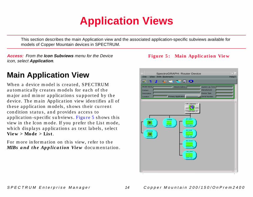
This section describes the main Application view and the associated application-specimodels of Copper Mountain devices in SPECTRUM.
cess: From the Icon Subviews menu for the Devicen, select Application .
ain Application Viewhen a device model is created, SPECTRUM tomatically creates models for each of the ajor and minor applications supported by the vice. The main Application view identifies all of ese application models, shows their current ndition status, and provides access to plication-specific subviews. Figure 5 shows this w in the Icon mode. If you prefer the List mode, ich displays applications as text labels, select
ew > Mode > List.
r more information on this view, refer to the Bs and the Application View documentation.
Figure 5: Mai
SpectroGRAPH: R
Model Name
Contact
Description
Location Primary Applicatio
Network Add
02_Routing
GenRtrApp
File View Tools Bookmarks
IP Routing
IP2RtrApp
rfc 1315
FrRelay
rfc 1315

A p S u p p o r t e d A p p l i c a t i o n s
S P n 2 0 0 / 1 5 0 / O n P r e m 2 4 0 0
SSPtw
••
CFothdedocoSP
•
ons
ath First
s
plications
NN
p l i c a t i o n V i e w s
E C T R U M E n t e r p r i s e M a n a g e r 15 C o p p e r M o u n t a i
upported ApplicationsECTRUM’s applications can be grouped within o general categories as follows:
Common Applications, belowDevice-Specific Applications (Page 16)
ommon Applicationsr the most part, these applications represent e non proprietary MIBs supported by your vice. Listed below (beneath the title of the cument that describes them) are some of the mmon applications currently supported by ECTRUM.
Bridging Applications- Spanning Tree- Static- Transparent- PPP Bridging- Source Routing- Translation
• Routing Applicati- Generic Routing- Repeater- AppleTalk- DECnet- Open Shortest P
• MIB II Application- SNMP- IP- ICMP- TCP- System2- UDP
• Miscellaneous Ap- FDDI- Point to Point- DS 1- RS-232- WAN- Frame Relay- Token Ring- DLSW- APPN- Ethernet- Fast Ethernet- ATM Client- DHCP
ote:ote:
The documents listed are available for viewing at:
www.aprisma.com/manuals/
A p s 3 A p p 1 4 0 7 A p p l i c a t i o n
S P n 2 0 0 / 1 5 0 / O n P r e m 2 4 0 0
DSPpr
••••
ThSP(reapco
Thspthlis
•
ion (ADSLLineApp)
pplicationes access to the following
ion Table (Page 16)ble (Page 18)ble (Page 19)
e (Page 20)
ation Tablebviews menu for theon, select DS3/E3
following fields.
terface on a managed ntry directly associated
interface, it will have the dex field.
lue of ifIndex from the II (RFC 1213).
NN
p l i c a t i o n V i e w s D
E C T R U M E n t e r p r i s e M a n a g e r 16 C o p p e r M o u n t a i
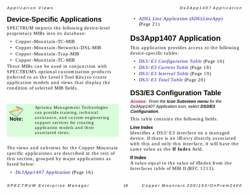
evice-Specific ApplicationsECTRUM imports the following device-level oprietary MIBs into its database:
Copper-Mountain-TC-MIBCopper-Mountain-Networks-DSL-MIBCopper-Mountain-Trap-MIBCopper-Mountain-TC-MIB
ese MIBs can be used in conjunction with ECTRUM’s optional customization products ferred to as the Level I Tool Kits) to create plication models and views that display the ndition of selected MIB fields.
e views and subviews for the Copper Mountain ecific applications are described in the rest of is section, grouped by major applications as ted below:
Ds3App1407 Application (Page 16)
• ADSL Line Applicat(Page 21)
Ds3App1407 AThis application providdevice-specific tables:
• DS3/E3 Configurat• DS3/E3 Current Ta• DS3/E3 Interval Ta• DS3/E3 Total Tabl
DS3/E3 ConfigurAccess: From the Icon SuDs3App1407 Application icConfiguration .
This table contains the
Line IndexIdentifies a DS3/E3 indevice. If there is an ifEwith this and only thissame value as the If In
If IndexA value equal to the vaInterfaces table of MIB
ote:ote:
Aprisma Management Technologies can provide training, technical assistance, and custom engineering support services for creating application models and their associated views.
A p s 3 A p p 1 4 0 7 A p p l i c a t i o n
S P n 2 0 0 / 1 5 0 / O n P r e m 2 4 0 0
TimThthm
VaThdath24nusin
LinThthinThMlismse
Suppression used on this sx3B3ZS and e3HDB3 refer atterns of normal bits and h are used to replace of a specified length. The dsx3Other .
tion of the DS3/E3 values are as follows:
n the loopback state. A apable of performing a terface always returns this
- the received signal at this through the device. Typi-
Specification
ANSI T1.107-1988
ANSI T1.107-1988
ANSI T1.107a-1989
ANSI T1.102-1987
CCITT G.751
ETSI T/NA(91)18.
p l i c a t i o n V i e w s D
E C T R U M E n t e r p r i s e M a n a g e r 17 C o p p e r M o u n t a i
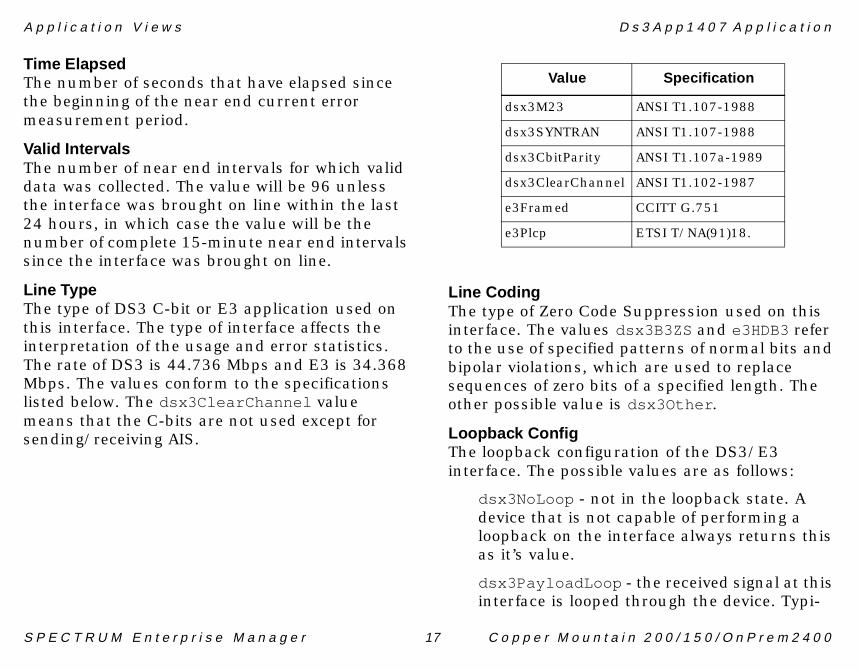
e Elapsede number of seconds that have elapsed since e beginning of the near end current error easurement period.
lid Intervalse number of near end intervals for which valid ta was collected. The value will be 96 unless e interface was brought on line within the last hours, in which case the value will be the mber of complete 15-minute near end intervals ce the interface was brought on line.
e Typee type of DS3 C-bit or E3 application used on is interface. The type of interface affects the terpretation of the usage and error statistics. e rate of DS3 is 44.736 Mbps and E3 is 34.368
bps. The values conform to the specifications ted below. The dsx3ClearChannel value eans that the C-bits are not used except for nding/receiving AIS.
Line CodingThe type of Zero Code interface. The values dto the use of specified pbipolar violations, whicsequences of zero bits other possible value is
Loopback ConfigThe loopback configurainterface. The possible
dsx3NoLoop - not idevice that is not cloopback on the inas it’s value.
dsx3PayloadLoop interface is looped
Value
dsx3M23
dsx3SYNTRAN
dsx3CbitParity
dsx3ClearChannel
e3Framed
e3Plcp
A p s 3 A p p 1 4 0 7 A p p l i c a t i o n
S P n 2 0 0 / 1 5 0 / O n P r e m 2 4 0 0
LinThloovathlooCodsfla
mit clock, which is derived eive clock of another DS3 values are loopTiming , ughTiming .
Tablebviews menu for theon, select DS3/E3 Current .
tistics for the DS3/E3 ng the current 15 minute tains the following fields.
dentifies the DS3/E3 entry is applicable.
rored seconds
1
2
4
8
16
LOF failure state
LOS failure state
looping the received signal
eceiving a Test Pattern
line status not defined
p l i c a t i o n V i e w s D
E C T R U M E n t e r p r i s e M a n a g e r 18 C o p p e r M o u n t a i
cally, the received signal is looped back for retransmission after it has passed through the device’s framing function.
dsx3LineLoop - the received signal at this interface does not go through the device (min-imum penetration) but is looped back out.
dsx3OtherLoop - loopbacks that are not defined here.
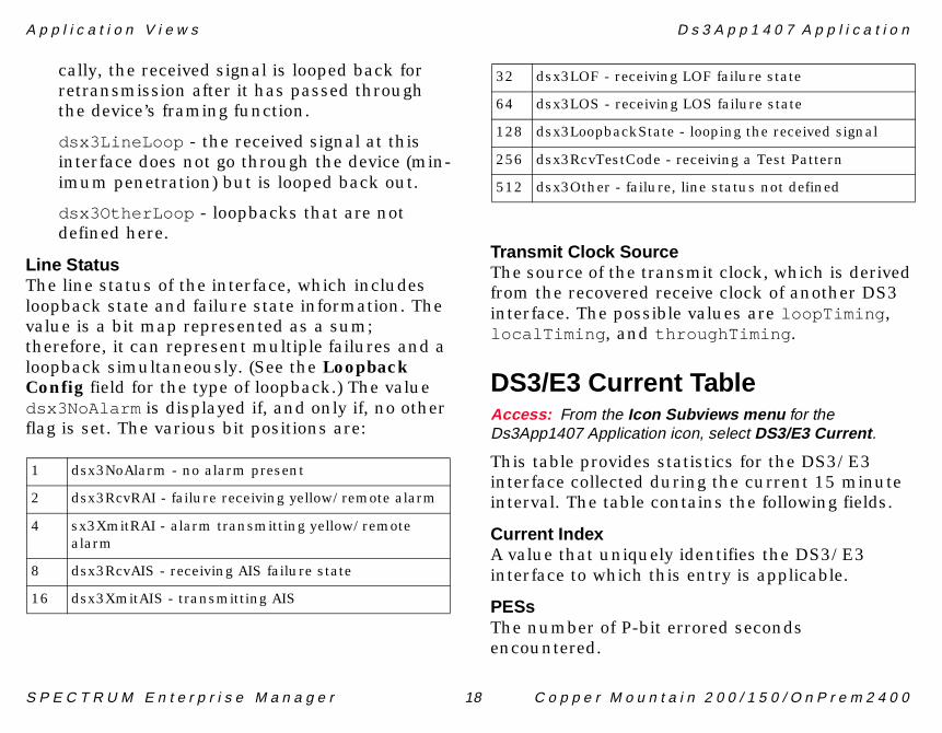
e Statuse line status of the interface, which includes pback state and failure state information. The lue is a bit map represented as a sum; erefore, it can represent multiple failures and a pback simultaneously. (See the Loopback nfig field for the type of loopback.) The value
x3NoAlarm is displayed if, and only if, no other g is set. The various bit positions are:
Transmit Clock SourceThe source of the transfrom the recovered recinterface. The possiblelocalTiming , and thro
DS3/E3 CurrentAccess: From the Icon SuDs3App1407 Application ic
This table provides stainterface collected duriinterval. The table con
Current IndexA value that uniquely iinterface to which this
PESsThe number of P-bit erencountered.
dsx3NoAlarm - no alarm present
dsx3RcvRAI - failure receiving yellow/remote alarm
sx3XmitRAI - alarm transmitting yellow/remote alarm
dsx3RcvAIS - receiving AIS failure state
dsx3XmitAIS - transmitting AIS
32 dsx3LOF - receiving
64 dsx3LOS - receiving
128 dsx3LoopbackState -
256 dsx3RcvTestCode - r
512 dsx3Other - failure,
A p s 3 A p p 1 4 0 7 A p p l i c a t i o n
S P n 2 0 0 / 1 5 0 / O n P r e m 2 4 0 0
PSThen
SEThen
UATh
LCTh
PCThen
LETh
CCThen
CEThen
CSThen
Tablebviews menu for theon, select DS3/E3 Interval .
tistics collected by each the previous 24 hours of period is broken into 96 tervals. The table contains
dentifies the DS3/E3 entry is applicable.
nd 96, where 1 is the most minute interval and 96 is leted 15 minute interval ntervals are valid).
rored seconds
verely errored seconds
errored framing seconds
p l i c a t i o n V i e w s D
E C T R U M E n t e r p r i s e M a n a g e r 19 C o p p e r M o u n t a i
ESse number of P-bit severely errored seconds countered.
FSse number of severely errored framing seconds countered.
Sse number of unavailable seconds encountered.
Vse number of line coding violations encountered.
Vse number of P-bit coding violations countered.
Sse number of line errored seconds encountered.
Vse number of C-bit coding violations countered.
Sse number of C-bit errored seconds countered.
ESse number of C-bit severely errored seconds countered.
DS3/E3 IntervalAccess: From the Icon SuDs3App1407 Application ic
This table provides staDS3/E3 interface overoperation. The 24 hourcompleted 15 minute inthe following fields.
Interval IndexA value that uniquely iinterface to which this
Interval NumberA number between 1 arecently completed 15 the least recently comp(assuming that all 96 i
PESsThe number of P-bit erencountered.
PSESsThe number of P-bit seencountered.
SEFSsThe number of severelyencountered.
A p s 3 A p p 1 4 0 7 A p p l i c a t i o n
S P n 2 0 0 / 1 5 0 / O n P r e m 2 4 0 0
UATh
LCTh
PCThen
LETh
CCThen
CEThen
CSThen
DAcDs
ThthTh
dentifies the DS3/E3 entry is applicable.
rored seconds
verely errored seconds
errored framing seconds
able seconds encountered.
ing violations encountered.
ding violations
ored seconds encountered.
ding violations
p l i c a t i o n V i e w s D
E C T R U M E n t e r p r i s e M a n a g e r 20 C o p p e r M o u n t a i
Sse number of unavailable seconds encountered.
Vse number of line coding violations encountered.
Vse number of P-bit coding violations countered.
Sse number of line errored seconds encountered.
Vse number of C-bit coding violations countered.
Sse number of C-bit errored seconds countered.
ESse number of C-bit severely errored seconds countered.
S3/E3 Total Tablecess: From the Icon Subviews menu for the3App1407 Application icon, select DS3/E3 Total .
is table provides the cumulative statistics for e 24 hour period preceding the current interval. e table contains the following fields.
Total IndexA value that uniquely iinterface to which this
PESsThe number of P-bit erencountered.
PSESsThe number of P-bit seencountered.
SEFSsThe number of severelyencountered.
UASsThe number of unavail
LCVsThe number of line cod
PCVsThe number of P-bit coencountered.
LESsThe number of line err
CCVsThe number of C-bit coencountered.
A p l i c a t i o n ( A D S L L i n e A p p )
S P n 2 0 0 / 1 5 0 / O n P r e m 2 4 0 0
CEThen
CSThen
A(AThAp
••••
•••
•
bviews menu for theine Table .
mon attributes describing
It is required for all ADSL SL physical interfaces are
pe is equal to adsl .
following information.
Table.
ing type used on this line.
SL physical line entity that ther and how the line is is channelized, the value annel . This field defines
are supported. In the case lized, the manager can use rmine the Index for the
-specific MIB. The determine shelf/slot/port n a DSLAM.
p l i c a t i o n V i e w s A D S L L i n e A p p
E C T R U M E n t e r p r i s e M a n a g e r 21 C o p p e r M o u n t a i
Sse number of C-bit errored seconds countered.
ESse number of C-bit severely errored seconds countered.
DSL Line ApplicationDSLLineApp)
e following views are available for the plication.
Line Table (Page 21)ATUC Physical Table View (Page 22)ATUC Performance Table View (Page 22)ATUC Channel Performance Table View (Page 23)ATUR Physical Table View (Page 23)ATUR Performance Table View (Page 24)ATUR Channel Performance Table View (Page 25)Configuration View (Page 25)
Line TableAccess: From the Icon SuADSLLineApp icon, select L
This table includes com
both ends of the line. physical interfaces. ADthose entries where Ty
This table provides the
InstanceAn entry in ADSL Line
CodingSpecifies the ADSL cod
TypeDefines the type of ADexists, by defining whechannelized. If the linewill be other than noChwhich channel type(s) that the line is channethe Stack Table to deteassociated channel(s).
SpecificOID instance in vendorInstance will be used toof the ATUC interface i
A p l i c a t i o n ( A D S L L i n e A p p )
S P n 2 0 0 / 1 5 0 / O n P r e m 2 4 0 0
ATAcAD
Throforen
Th
InsAn
StIn
AtInragr
SeThve
VeThidex
sion number sent by this alization messages. It is a on number field defined by ssed as readable
ce Table Viewbviews menu for theTUC Performance Table .
tables containing on for total and daily The list below describe the ly values simply substitute last agent reset”. This
for each ATUC. ADSL those entries where Type
e following information.
ance table.
f Errored Seconds since d second parameter is a tervals containing one or one or more los or sef
p l i c a t i o n V i e w s A D S L L i n e A p p
E C T R U M E n t e r p r i s e M a n a g e r 22 C o p p e r M o u n t a i
UC Physical Table Viewcess: From the Icon Subviews menu for theSLLineApp icon, select ATUC Physical Table .
is table provides one row for each ATUC. Each w contains the Physical Layer Parameters table that ATUC. ADSL physical interfaces are those tries where Type is equal to adsl .
is view provides the following information.
tance entry in the ATUC Physical Table.
atusdicates current state of the ATUC line.
tainable Ratedicates the maximum currently attainable data te by the ATU. This value will be equal or eater than the current line rate.
rial Numbere vendor specific string that identifies the ndor equipment.
ndor IDe vendor ID code is a copy of the binary vendor
entification field defined by the PHY[10] and pressed as readable characters.
Version NumberThe vendor specific verATU as part of the initicopy of the binary versithe PHY[10] and exprecharacters.
ATUC PerformanAccess: From the Icon SuADSLLineApp icon, select A
This view provides twoPerformance informatiperformance statistics.total value, and for dai“in 24 hours” for “sincetable provides one rowphysical interfaces areis equal to adsl.
These tables provide th
InstanceAn entry in the Perform
Error SecondsCount of the number oagent reset. The errorecount of one-second inmore crc anomalies, ordefects.
A p l i c a t i o n ( A D S L L i n e A p p )
S P n 2 0 0 / 1 5 0 / O n P r e m 2 4 0 0
IntCoagat
LoCosin
LoCoag
LoCosin
LoCosin
ATVAcADTa
ThPeac
e following information.
hannel Performance table.
locks transmitted on this set.
locks received on this set.
eived with errors that were eset. These blocks are .
eived with uncorrectable t.
able Viewbviews menu for theTUR Physical Table .
row for each ATUR. Each cal Layer Parameters table hysical interfaces are those qual to adsl .
following information.
p l i c a t i o n V i e w s A D S L L i n e A p p
E C T R U M E n t e r p r i s e M a n a g e r 23 C o p p e r M o u n t a i
ializiationsunt of the line initialization attempts since ent reset. Includes both successful and failed tempts.
ss of Frameunt of the number of Loss of Framing failures ce agent reset.
ss of Linkunt of the number of Loss of Link failures since ent reset.
ss of Signalunt of the number of Loss of Signal failures ce agent reset.
ss of Powerunt of the number of Loss of Power failures ce agent reset.
UC Channel Performance Tableiewcess: From the Icon Subviews menu for theSLLineApp icon, select ATUC Channel Performance
ble .
is view provides two tables containing rformance statistics for daily and total cumulations.
These tables provide th
InstanceAn entry in the ATUC C
Transmitted BlocksCount of all encoded bchannel since agent re
Received BlocksCount of all encoded bchannel since agent re
Corrected BlocksCount of all blocks reccorrected since agent rpassed on as good data
Uncorrect BlocksCount of all blocks recerrors since agent rese
ATUR Physical TAccess: From the Icon SuADSLLineApp icon, select A
This table provides onerow contains the Physifor that ATUR. ADSL pentries where Type is e
This view provides the
A p l i c a t i o n ( A D S L L i n e A p p )
S P n 2 0 0 / 1 5 0 / O n P r e m 2 4 0 0
InsAn
StIn
AtInragr
SeThve
VeThidex
VeThATcothch
ATAcAD
tables containing on for total
statistics. This table ch ATUR. ADSL physical
tries where Type is equal to
e following information.
ance table.
f Errored Seconds since d second parameter is a tervals containing one or one or more los or sef
lization attempts since oth successful and failed
f Loss of Framing failures
f Loss of Link failures since
p l i c a t i o n V i e w s A D S L L i n e A p p
E C T R U M E n t e r p r i s e M a n a g e r 24 C o p p e r M o u n t a i
tance entry in the ATUR Physical Table.
atusdicates current state of the ATUR line.
tainable Ratedicates the maximum currently attainable data te by the ATU. This value will be equal or eater than the current line rate.
rial Numbere vendor specific string that identifies the ndor equipment.
ndor IDe vendor ID code is a copy of the binary vendor
entification field defined by the PHY[10] and pressed as readable characters.
rsion Numbere vendor specific version number sent by this U as part of the initialization messages. It is a py of the binary version number field defined by e PHY[10] and expressed as readable aracters.
UR Performance Table Viewcess: From the Icon Subviews menu for theSLLineApp icon, select ATUR Performance Table .
This view provides towPerformance informati
and daily performanceprovides one row for eainterfaces are those enadsl.
These tables provide th
InstanceAn entry in the Perform
Error SecondsCount of the number oagent reset. The errorecount of one-second inmore crc anomalies, ordefects.
IntializiationsCount of the line initiaagent reset. Includes battempts.
Loss of FrameCount of the number osince agent reset.
Loss of LinkCount of the number oagent reset.
A p l i c a t i o n ( A D S L L i n e A p p )
S P n 2 0 0 / 1 5 0 / O n P r e m 2 4 0 0
LoCosin
LoCosin
ATVAcADTa
ThPeac
Th
InsTh
TraCoch
ReCoch
eived with errors that were eset. These blocks are .
eived with uncorrectable t.
wbviews menu for the
onfiguration View .
has one field called Alarm e of FALSE by default. If it
e device model passes a model, the alert handler ent on the device model. If E, the alert handler will an alarm on the device
p l i c a t i o n V i e w s A D S L L i n e A p p
E C T R U M E n t e r p r i s e M a n a g e r 25 C o p p e r M o u n t a i
ss of Signalunt of the number of Loss of Signal failures ce agent reset.
ss of Powerunt of the number of Loss of Power failures ce agent reset.
UR Channel Performance Tableiewcess: From the Icon Subviews menu for theSLLineApp icon, select ATUR Channel Performance
ble .
is view provides two tables containing rformance statistics for daily and total cumulations.
ese tables provide the following information.
tanceis indicates that there is an entry in this table.
nsmitted Blocksunt of all encoded blocks transmitted on this annel since agent reset.
ceived Blocksunt of all encoded blocks received on this annel since agent reset.
Corrected BlocksCount of all blocks reccorrected since agent rpassed on as good data
Uncorrect BlocksCount of all blocks recerrors since agent rese
Configuration VieAccess: From the Icon SuADSLLineApp icon, select C
The Configuration viewOn Traps. It has a valuis set to FALSE, and thtrap to the applicationwill only generate an evAlarm On Traps is TRUgenerate an event and model.

S P n 2 0 0 / 1 5 0 / O n P r e m 2 4 0 0
of Copper Mountain
Peinceis coreforta
GedefrodethIn
Foto
Thatsu
e Performance View
PH: Type Routing
System Up Time
Manufacturer
Device Type
Serial Number
Value Average Peak Value
t
Detailperties Scroll to Date-Time
*Frames per second
pe node: Primary
ation
E C T R U M E n t e r p r i s e M a n a g e r 26 C o p p e r M o u n t a i
Performance Views
This section provides brief descriptions of the Performance views available for modelsdevices in SPECTRUM.
rformance views display performance statistics terms of a set of transmission attributes, e.g., ll rates, frame rates, % error, etc. A typical view shown in Figure 6. The instantaneous ndition of each transmission attribute is corded in a graph. The statistical information each attribute is presented in the adjacent
ble.
nerally, you determine performance at the vice level through Performance views accessed m the Device and Application icons. You termine performance at the port/interface level rough Performance views accessed from terface icons.
r more information on Performance views, refer the SPECTRUM Views documentation.
e following paragraphs list the performance tributes displayed for each Performance view pported by this management module..
Figure 6: Devic
SpectroGRA
Model Name
Contact
Description
Location
Network Address
Log
100.0
10.00
1.00
0.10
0.01
000:40:0 0:30:0 0:20:0
* Frame Rate
% Delivered
% Forwarded
% Transmi
% Error
Graph Pro
File View Tools Bookmarks
% Discarded
type routing of type IP Routing of Landsca
Primary Applic

P e P e r f o r m a n c e V i e w
S P n 2 0 0 / 1 5 0 / O n P r e m 2 4 0 0
PAcMo
Thstath
••••••
r f o r m a n c e V i e w s
E C T R U M E n t e r p r i s e M a n a g e r 27 C o p p e r M o u n t a i
erformance Viewcess: From the Icon Subviews menu for the Copperuntain Device icon, select Performance.
is view provides the following performance tistics about the packets being passed through
e device:
Frame Rate% Delivered% Forwarded% Transmitted% Error% Discarded
S P n 2 0 0 / 1 5 0 / O n P r e m 2 4 0 0
els of Copper Mountain
CocuinCoCo
•
DAcMo
ThcowhprTrescovieth
e Configuration View
H: Model Name
lication
System Up Time
Manufacturer
Device Type
Serial Number
figuration View
nfiguration Table
Max Frame Size Operational Status
nd scape node: Primary
Help
E C T R U M E n t e r p r i s e M a n a g e r 28 C o p p e r M o u n t a i
Configuration Views
This section describes the various Configuration views and subviews available for moddevices in SPECTRUM.
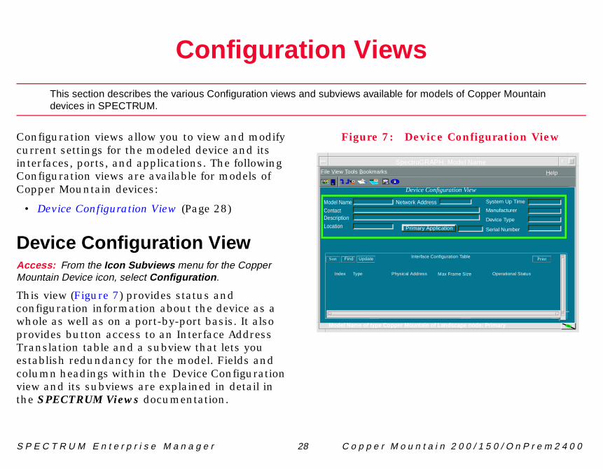
nfiguration views allow you to view and modify rrent settings for the modeled device and its terfaces, ports, and applications. The following nfiguration views are available for models of pper Mountain devices:
Device Configuration View (Page 28)
evice Configuration Viewcess: From the Icon Subviews menu for the Copperuntain Device icon, select Configuration .
is view (Figure 7) provides status and nfiguration information about the device as a ole as well as on a port-by-port basis. It also
ovides button access to an Interface Address anslation table and a subview that lets you tablish redundancy for the model. Fields and lumn headings within the Device Configuration w and its subviews are explained in detail in e SPECTRUM Views documentation.
Figure 7: Devic
SpectroGRAP
Primary App
Network AddressModel NameContactDescriptionLocation
Device Con
Interface CoSort Find Update
File View Tools Bookmarks
Index Type Physical Address
Model Name of type Copper Mountain of La
C o v i c e C o n f i g u r a t i o n V i e w
S P n 2 0 0 / 1 5 0 / O n P r e m 2 4 0 0
InAcIntCo
Thth
OpThOf
AdThOf
LaThen
IPThna
PhTh
BaThm
th, or no accurate estimate l bandwidth is provided.
t can be transmitted or isplayed in octets.
und packet queue, in
n f i g u r a t i o n V i e w s D e
E C T R U M E n t e r p r i s e M a n a g e r 29 C o p p e r M o u n t a i
terface Configuration Viewcess: From the Icon Subviews menu for a selectederface icon in the Interface Device view, select IFnfiguration .
is view provides the following information for e selected interface:
eration Statuse current operational state of the interface (On, f, or Testing).
min. Statuse desired operational state of the interface (On, f, or Testing).
st Changee System UpTime value when the interface tered its current operational state.
Address/Network Maskis window provides a list of the user-defined mes and IP addresses for the interface.
ysical Addresse Ethernet (MAC) address of the interface.
ndwidthe estimated bandwidth of the interface,
easured in bits per second. For interfaces that
do not vary in bandwidcan be made, a nomina
Packet SizeThe largest packet thareceived by the port, d
Queue LengthThe length of the outbopackets.
S P n 2 0 0 / 1 5 0 / O n P r e m 2 4 0 0
provided with this view.
AcMo
ThhotyalsThansotra
Alarm Counter View
APH: Router Device
üóò
�ù�ô�ûÿ�÷ÿ�üû��òô�ý�úõ�ÿ�ù÷�
�òô�ý�úõ�ÿ�ò���
��ýüúöÿ��û��ý
����ÿ
Counter View
Counter Attributes
Major Alarm Count
Trap Count Warning
E C T R U M E n t e r p r i s e M a n a g e r 30 C o p p e r M o u n t a i
Trap Alarm Counter View
This section provides information on the various indicators of alarms and alarm types
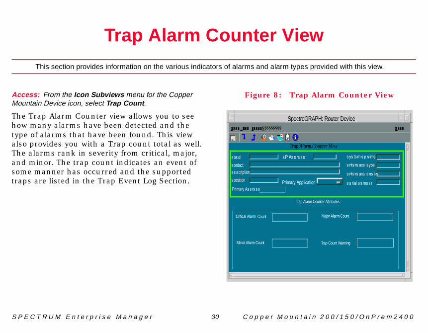
cess: From the Icon Subviews menu for the Copperuntain Device icon, select Trap Count .
e Trap Alarm Counter view allows you to see w many alarms have been detected and the pe of alarms that have been found. This view o provides you with a Trap count total as well. e alarms rank in severity from critical, major, d minor. The trap count indicates an event of me manner has occurred and the supported ps are listed in the Trap Event Log Section.
Figure 8: Trap
SpectroGR
þýüûúýùÿø÷÷öüõúô
�þÿø��ý����ó��öÿ�óòôúõô���õýü÷ôüóò�óõúôüóò
ÿ����ÿ ����
þýüûúýùÿø��ý���
Trap Alarm
�����ÿ���������
Trap Alarm
Critical Alarm Count
Minor Alarm Count

T r l a r m C o u n t e r A t t r i b u t e s
S P n 2 0 0 / 1 5 0 / O n P r e m 2 4 0 0
TrThfol
CrDi
MaDi
MiDi
TraDiTrsu
a p A l a r m C o u n t e r V i e w T r a p A
E C T R U M E n t e r p r i s e M a n a g e r 31 C o p p e r M o u n t a i
ap Alarm Counter Attributese Trap Alarm Counter Attributes provide the lowing information:
itical Alarmsplays the number of uncleared critical alarms.
jorsplays the number of uncleared major alarms.
norsplays the number of uncleared minor alarms.
pssplays the number of uncleared traps. See the ap Event Table (Page 33) for further details on pported traps.
S P n 2 0 0 / 1 5 0 / O n P r e m 2 4 0 0
ThhadideTaininevonDS
p Event Log View
Device
üóò
�ù�ô�ûÿ�÷ÿ�üû��òô�ý�úõ�ÿ�ù÷�
�òô�ý�úõ�ÿ�ò���
��ýüúöÿ��û��ý
����ÿ
Table
b Cause Severity Time Tag Text
E C T R U M E n t e r p r i s e M a n a g e r 32 C o p p e r M o u n t a i
Trap Event Log View
This section provides details of the events and traps on the monitored device.
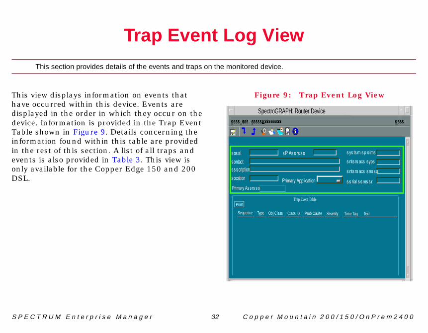
is view displays information on events that ve occurred within this device. Events are
splayed in the order in which they occur on the vice. Information is provided in the Trap Event ble shown in Figure 9. Details concerning the formation found within this table are provided the rest of this section. A list of all traps and ents is also provided in Table 3. This view is ly available for the Copper Edge 150 and 200 L.
Figure 9: Tra
SpectroGRAPH: Router
þýüûúýùÿø÷÷öüõúô
�þÿø��ý����ó��öÿ�óòôúõô���õýü÷ôüóò�óõúôüóò
ÿ����ÿ ����
þýüûúýùÿø��ý���
Trap Event
�����ÿ���������
Sequence Type Obj Class Class ID Pro

T r T r a p E v e n t T a b l e
S P n 2 0 0 / 1 5 0 / O n P r e m 2 4 0 0
TrThocco
SeThde
TyDi
ObDire
ClDiTawi
rap Definitions
Definition
dicates an operator tried d failed to log into the stem.
dicates that and ccessfully logged into the stem.
dicates that an operator s successfully logged out
the system.
dicates that the maximum mber of operators are rrently logged into the stem. No more logins will allowed until one of them gs out.
dicates that logins are lowed again.
dicates that the indicated stem board has tablished communication th System Control odule.
a p E v e n t L o g V i e w
E C T R U M E n t e r p r i s e M a n a g e r 33 C o p p e r M o u n t a i
ap Event Tableis table contains information on the events that cur on the Copper Mountain devices. This table ntains the following information:
quencee order in which the events occurred on the vice.
pesplays the type of event that has occurred.
j Classsplays the object class associated with the source reporting the event.
ass IDsplays the object class that generated the event. ble 3 defines list the traps that are associated th the field.
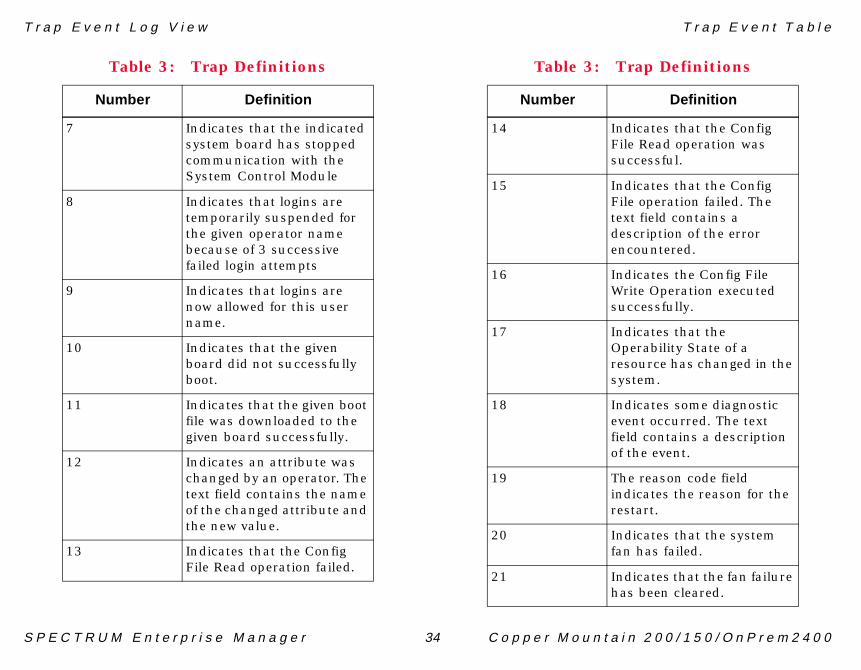
Table 3: T
Number
1 Inansy
2 Insusy
3 Inhaof
4 Innucusybelo
5 Inal
6 InsyeswiM
T r T r a p E v e n t T a b l e
S P n 2 0 0 / 1 5 0 / O n P r e m 2 4 0 0
dicates that the Config le Read operation was ccessful.
dicates that the Config le operation failed. The xt field contains a scription of the error countered.
dicates the Config File rite Operation executed ccessfully.
dicates that the erability State of a
source has changed in the stem.
dicates some diagnostic ent occurred. The text ld contains a description the event.
e reason code field dicates the reason for the start.
dicates that the system n has failed.
dicates that the fan failure s been cleared.
rap Definitions
Definition
a p E v e n t L o g V i e w
E C T R U M E n t e r p r i s e M a n a g e r 34 C o p p e r M o u n t a i
7 Indicates that the indicated system board has stopped communication with the System Control Module
8 Indicates that logins are temporarily suspended for the given operator name because of 3 successive failed login attempts
9 Indicates that logins are now allowed for this user name.
10 Indicates that the given board did not successfully boot.
11 Indicates that the given boot file was downloaded to the given board successfully.
12 Indicates an attribute was changed by an operator. The text field contains the name of the changed attribute and the new value.
13 Indicates that the Config File Read operation failed.
Table 3: Trap Definitions
Number Definition
14 InFisu
15 InFitedeen
16 InWsu
17 InOpresy
18 Inevfieof
19 Thinre
20 Infa
21 Inha
Table 3: T
Number
T r T r a p E v e n t T a b l e
S P n 2 0 0 / 1 5 0 / O n P r e m 2 4 0 0
nt whenever an SCM tects redundancy has anged from abled/disabled to sabled/enabled.
nt when an SCM comes , detects that it should be
cked as the Primary SCM, t there is another Primary ich has already locked
e system (i.e. Disabled dundancy).
dicates a maintenance mmand completed ccessfully or failed cording to the mmandStatus field.
nt at the end of an terval when an object that configured with a Falling reshold that has dropped low the fallingThreshold lue in the cmAlarmTable.
is trap is sent whenever a odem trains at a rate less an the configured tabase.
rap Definitions
Definition
a p E v e n t L o g V i e w
E C T R U M E n t e r p r i s e M a n a g e r 35 C o p p e r M o u n t a i
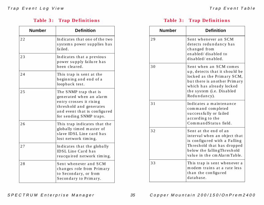
22 Indicates that one of the two systems power supplies has failed.
23 Indicates that a previous power supply failure has been cleared.
24 This trap is sent at the beginning and end of a loopback test.
25 The SNMP trap that is generated when an alarm entry crosses it rising threshold and generates and event that is configured for sending SNMP traps.
26 This trap indicates that the globally timed master of slave IDSL Line card has lost network timing.
27 Indicates that the globally IDSL Line Card has reacquired network timing.
28 Sent whenever and SCM changes role from Primary to Secondary, or from Secondary to Primary.
Table 3: Trap Definitions
Number Definition
29 Sedechendi
30 SeuplobuwhthRe
31 IncosuacCo
32 SeinisThbeva
33 Thmthda
Table 3: T
Number
T r T r a p E v e n t T a b l e
S P n 2 0 0 / 1 5 0 / O n P r e m 2 4 0 0
cause of the event.
ssigned to this event by the
vent occurred.
l information needed to
is is sent whenever the ug and Play failure is eared.
rap Definitions
Definition
a p E v e n t L o g V i e w
E C T R U M E n t e r p r i s e M a n a g e r 36 C o p p e r M o u n t a i
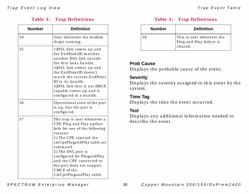
Prob CauseDisplays the probable
SeverityDisplays the severity asystem.
Time TagDisplays the time the e
TextDisplays any additionadescribe the event.
34 Sent whenever the modem drops training.
35 1)DSL link comes up and the EndPointID matches another DSL link outside the first links bundle. 2)DSL link comes up and the EndPointID doesn’t match the current EndPoint ID in its bundle.3)DSL link that is not IMUX capable comes up and is configured in a bundle.
36 Operational state of the port is up, but the port is configured.
37 The trap is sent whenever a CPE Plug and Play update fails for one of the following reasons:1) The CPE rejected the cmCpePlugandPlay table set command.2) The DSL port is configured for PlugandPlay and the CPE connected to the port does not support CMCP of the CmCpePlugandPlay table.
Table 3: Trap Definitions
Number Definition
38 ThPlcl
Table 3: T
Number

S P n 2 0 0 / 1 5 0 / O n P r e m 2 4 0 0
nager
on these optional
ThMfuinM
AnMApfor
InFo
1
2
3
4
iables:
play Type:
PPEREXCPATH=/<Copper ath>/binn.
roGRAPH. The menu the Copper Mountain
ntains Application Suite ter as the
nstalled on.
ctroGRAPH.
UM
60.env
REXC=/<Copper Mountain
E C T R U M E n t e r p r i s e M a n a g e r 37 C o p p e r M o u n t a i
Copper View/Copper Element Ma
This section describes and directs you to the Copper Mountain site for documentationApplications.
ese views are an optional feature for the Copper ountain 200/150/OnPrem2400 that provide rther configuration and management formation. For the information see the Copper outon website.
additional menu pick will appear for Copper ountain's Element Manager and Copper View plications by setting an environmental variable both NT and Solaris Platforms.
structionsr NT users:
Install Copper Mountains Application Suite on the same computer as the SpectroGRAPH is installed on.
Shutdown the SpectroGRAPH.
Bring up the Control Panel.
Select the Environment Tab.
5 Add to System Var
• For Set Entries DisCOPPEREXCPATH
• For Value Type: COMountain Install P
6 Click the Set Butto
7 Bring up the Spectshould now containMenu Picks.
For Solaris users:
1 Install Copper Mouon the same compuSpectroGRAPH is i
2 Shutdown the Spe
3 cd to /opt/SPECTR
4 As root, vi spectrum
5 Add Entry: COPPEInstall Path>/bin
C o T r a p E v e n t T a b l e
S P n 2 0 0 / 1 5 0 / O n P r e m 2 4 0 0
6
p p e r V i e w / C o p p e r E l e m e n t M a n a g e r
E C T R U M E n t e r p r i s e M a n a g e r 38 C o p p e r M o u n t a i
Bring up the SpectroGRAPH. The menu should now contain them Copper Mountain Menu Picks.
S P n 2 0 0 / 1 5 0 / O n P r e m 2 4 0 0
dels of Copper Mountain
Thabse
Fiviemwitoco
el Information View
ter Device
tion
System Up Time
Manufacturer
Device Type
Serial Number
s
Help?
Communication Information
Community Name
DCM TimeOut
DCM Retry
Poll/Log InformationPoll Interval
Polling Status
Last Successful Poll
Log Ratio
LOGGED POLLED
ation View
E C T R U M E n t e r p r i s e M a n a g e r 39 C o p p e r M o u n t a i
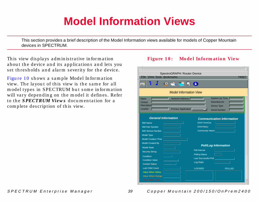
Model Information Views
This section provides a brief description of the Model Information views available for modevices in SPECTRUM.
is view displays administrative information out the device and its applications and lets you t thresholds and alarm severity for the device.
gure 10 shows a sample Model Information w. The layout of this view is the same for all
odel types in SPECTRUM but some information ll vary depending on the model it defines. Refer the SPECTRUM Views documentation for a mplete description of this view.
Figure 10: Mod
SpectroGRAPH: Rou
Primary Applica
Network AddresNameContactDescriptionLocation
File View
MM Version Number
MM Name
MM Part Number
General Information
Model Created By
Model Type
Model Creation Time
Model State
Security String
Condition
Condition Value
Contact Status
Lost Child Count
Value When Yellow
Value When Orange
Value When Red
Model Inform
Tools Bookmarks
D e n 2 0 0 / 1 5 0 / O n P r e m D S L
AAdAdAdAp
BBa
CC-CCCECo
ICo
DCoCS
Interface Number Label 10Interface Type Label 10Physical Address Label 11hange 292019, 20ode Violations 19tatus 18ype 17ack Configuration 17
Information views 39
nd Intervals 17rk I/O ports 13
tion Status 29tional Status 12s 39
v i c e M a n a g e m e n t Page 40 C o p p e r M o u n t a i
41
Index
dress Translation table 12min. Status 29ministrative Status 12plications 14
ndwidth 29
bit Information 18Vs 19, 20Ss 19, 20, 21lorsnterface Status Label 10nfigurationS3/E3 16
nfiguration views 28Es 19, 20, 21
DDevice Configuration View 28Devices supported by this module 6DS/E3 Information 16
IIcon Subviews Menus
for Interface icon 11Icons
Interface 10, 13Interface Configuration View 29Interface icon 10Interface Icon Subviews Menu
Options 11Interface Status View 12
Administrative Status 12Operational Status 12
IP Address/Network Mask 29
LLabels
InterfaceIF Status Label 10
Last CLCVsLESsLine CLine SLine TLoopb
MModel
NNear ENetwo
OOperaOperaOption
I n I n d e x
D e n 2 0 0 / 1 5 0 / O n P r e m D S L
PPaP-PCPePEPhPS
QQu
RReRe
SSeSESeSt
DSu
d e x
v i c e M a n a g e m e n t Page 41 C o p p e r M o u n t a i
cket Size 29bit Information 18Vs 19, 20rformance View 27Ss 18, 19ysical Address 29Es 19
eue Length 29
quired Reading 5stricted Rights Notice 2
condary Address Panel 12Fs 19, 20rial ports 13atistics
S3/E3 19, 20pported devices 6
TTime Elapsed 17Trademarks 2Transmit Clock Source 18Trap Event Table 32
UUASs 19, 20
VViews
Configuration 28Device Configuration 28Interface Configuration 29Interface Status 12Model Information 39Performance 26
ZZero Code Suppression 17