Copley Motion Objects (CMO) Programmer’s Guide · Copley Motion Objects (CMO) Programmer’s...
76
Copley Motion Objects (CMO) Programmer’s Guide P/N 95-00290-000 Revision 4 June 2008
Transcript of Copley Motion Objects (CMO) Programmer’s Guide · Copley Motion Objects (CMO) Programmer’s...
Copley Motion Objects (CMO) Programmer’s Guide
P/N 95-00290-000
Revision 4 June 2008

CMO Programmer’s Guide
Copley Controls Corp. i
TABLE OF CONTENTS Product Warnings............................................................................................................................................ ii About This Manual ......................................................................................................................................... iii 1: Introduction ............................................................................................................................................. 1
1.1: Windows-Based Control of Copley Amplifiers ................................................................................... 2 1.2: Basic System Requirements .............................................................................................................. 3
2: Installation ............................................................................................................................................... 5 2.1: Installation Overview .......................................................................................................................... 6 2.2: Installation Procedures....................................................................................................................... 6
3: Fundamental Concepts and Procedures .............................................................................................. 7 3.1: Before Running a Copley Motion Objects Program ........................................................................... 8 3.2: CAN Network...................................................................................................................................... 9 3.3: Adding a Reference to a Program.................................................................................................... 10 3.4: Object Initialization Sequence.......................................................................................................... 12 3.5: Objects Contained by AmpObj......................................................................................................... 12 3.6: Node Guarding ................................................................................................................................. 14 3.7: Error Handling .................................................................................................................................. 15 3.8: Units ................................................................................................................................................. 15 3.9: Stepnet Amplifiers ............................................................................................................................ 16
A: CANopen Object ....................................................................................................................................... 17 A.1: CANopen ......................................................................................................................................... 17
B: Amplifier and Related Objects ................................................................................................................ 19 B.1: AmpSettingsObj ............................................................................................................................... 20 B.2: Amplifier Initialization ....................................................................................................................... 21 B.3: Amplifier Information ........................................................................................................................ 21 B.4: Motor/Feedback Information............................................................................................................ 24 B.5: Save/Restore Amplifier Data ........................................................................................................... 27 B.6: Node Guarding................................................................................................................................. 27 B.7: Current Loop .................................................................................................................................... 27 B.8: Velocity Loop ................................................................................................................................... 29 B.9: Position Loop ................................................................................................................................... 30 B.10: Tracking Windows.......................................................................................................................... 31 B.11: Status, Events, and Faults............................................................................................................. 31 B.12: Amplifier Digital Inputs/Outputs ..................................................................................................... 35 B.13: Amplifier Enable/Disable................................................................................................................ 39 B.14: Homing........................................................................................................................................... 40 B.15: Quick Stop ..................................................................................................................................... 43 B.16: Point-to-Point Moves...................................................................................................................... 44 B.17: Amplifier Events ............................................................................................................................. 45 B.18: Amplifier Trace Methods and Properties ....................................................................................... 46 B.19: Other Methods and Properties....................................................................................................... 49
C: The Linkage Object................................................................................................................................... 53 C.1: Linkage Object (LinkageObj) ........................................................................................................... 53
D: The Event Object ...................................................................................................................................... 57 D.1: Event Object .................................................................................................................................... 58
E: The I/O Object............................................................................................................................................ 59 E.1: I/O Modules...................................................................................................................................... 60
F: CopleyMotionLibrary Object.................................................................................................................... 65 F.1: CopleyMotionLibraryObj .................................................................................................................. 66
G: Masking ..................................................................................................................................................... 67 G.1: Masking ........................................................................................................................................... 67
H: Object Revision History ........................................................................................................................... 69 H.1: Object Revision History ................................................................................................................... 69
CMO Programmer’s Guide Product Warnings
Copley Controls Corp. ii
PRODUCT WARNINGS Use caution in designing and programming machines that affect the safety of operators. !
WARNING
The examples in this book are for demonstration purposes only, providing guidelines for programming. The programmer is responsible for creating program code that operates safely for the amplifiers and motors in any given machine.
Failure to adhere to this warning can cause equipment damage, injury, or death.
Do not use Copley Motion Objects to implement an Emergency Stop
!WARNING
An Emergency Stop must be hardwired directly to the amplifier. Do not depend on the Copley Motion Objects software to provide for a timely emergency stop. Due to the non-deterministic nature of Microsoft Windows, the software cannot guarantee a timely emergency stop operation.
Failure to adhere to this warning can cause equipment damage, injury, or death.
CMO Programmer’s Guide About this Manual
Copley Controls Corp. iii
ABOUT THIS MANUAL Overview and Scope This manual describes the installation and use of Copley Motion Objects.
Related Documentation Readers of this book should also read information on CAN and CANopen at the “CAN in Automation” website at http://www.can-cia.de/.More information on the Copley Controls implementation of CANopen objects can be found in Copley Controls’ CANopen Programmer’s Manual:http://www.copleycontrols.com/Motion/pdf/CANopenProgrammersManual.pdf For information on connecting an amplifier to the CANopen Network, see Copley Controls CANopen Network CANBus Cabling Guide at: http://www.copleycontrols.com/Motion/pdf/CAN-Bus.pdf.Information on other Copley Controls Software can be found at: http://www.copleycontrols.com/Motion/Products/Software/index.html.For more information on Microsoft’s COM architecture, please refer to: http://www.microsoft.com/com/.
Comments Copley Controls Corp. welcomes your comments on this manual. See http://www.copleycontrols.com for contact information.
Copyrights No part of this document may be reproduced in any form or by any means, electronic or mechanical, including photocopying, without express written permission of Copley Controls Corp. CME 2 and CMO are registered trademarks of Copley Controls Corporation. Windows NT, 2000, and XP, Visual Basic, and .NET are trademarks or registered trademarks of the Microsoft Corporation. LabVIEW is a registered trademark of National Instruments.
Document Validity We reserve the right to modify our products. The information in this document is subject to change without notice and does not represent a commitment by Copley Controls Corp. Copley Controls Corp. assumes no responsibility for any errors that may appear in this document.
Revision History Release Date DECO # Comments 1.0 September 2003 Initial publication. 1.1 March 2004 Reorganized. 3 December 2006 14845 New features. 4 June 2008 17137 Updated Web page references.

Copley Controls Corp. 1
CHAPTER 1: INTRODUCTION
This chapter provides an overview of Copley Motion Objects. Contents include:
1.1: Windows-Based Control of Copley Amplifiers ................................................................................... 2 1.1.1: Simplified Access to CANopen Functions............................................................................... 2 1.1.2: Architectural Overview ............................................................................................................ 2
1.2: Basic System Requirements .............................................................................................................. 3 1.2.1: Computer and Operating System ........................................................................................... 3 1.2.2: Software .................................................................................................................................. 3 1.2.3: CAN Interface Card................................................................................................................. 3 1.2.4: Amplifier Firmware .................................................................................................................. 3
Introduction CMO Programmer’s Guide
2 Copley Controls Corp.
1.1: Windows-Based Control of Copley Amplifiers 1.1.1: Simplified Access to CANopen Functions
The Copley Motion Objects simplify creation of Windows-based software for the control of Copley Controls amplifiers over a CANopen network. They give programmers direct access to an amplifier’s CANopen functions without having to learn the complexities of CANopen objects. Copley Motion Objects were built using the Microsoft Component Object Model (COM) architecture, and are fully automation compliant. This means that any Microsoft COM-compliant software can access the Copley Motion Objects.
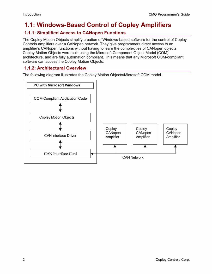
1.1.2: Architectural Overview The following diagram illustrates the Copley Motion Objects/Microsoft COM model.
CAN Interface Card
PC with Microsoft Windows
CopleyCANopenAmplifier
CopleyCANopenAmplifier
CopleyCANopenAmplifierCAN Interface Driver
Copley Motion Objects
COM-Compliant Application Code
CAN Network
CMO Programmer’s Guide Introduction
Copley Controls Corp. 3
1.2: Basic System Requirements 1.2.1: Computer and Operating System
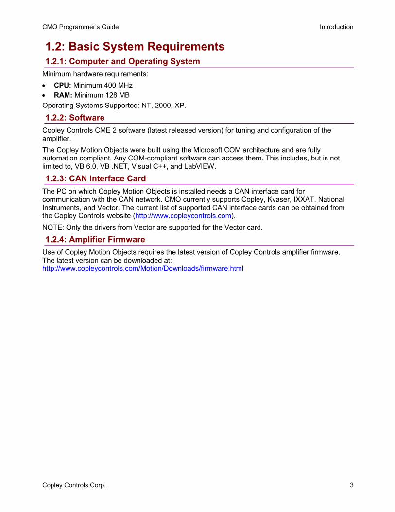
Minimum hardware requirements: • CPU: Minimum 400 MHz • RAM: Minimum 128 MB Operating Systems Supported: NT, 2000, XP.
1.2.2: Software Copley Controls CME 2 software (latest released version) for tuning and configuration of the amplifier. The Copley Motion Objects were built using the Microsoft COM architecture and are fully automation compliant. Any COM-compliant software can access them. This includes, but is not limited to, VB 6.0, VB .NET, Visual C++, and LabVIEW.
1.2.3: CAN Interface Card The PC on which Copley Motion Objects is installed needs a CAN interface card for communication with the CAN network. CMO currently supports Copley, Kvaser, IXXAT, National Instruments, and Vector. The current list of supported CAN interface cards can be obtained from the Copley Controls website (http://www.copleycontrols.com). NOTE: Only the drivers from Vector are supported for the Vector card.
1.2.4: Amplifier Firmware Use of Copley Motion Objects requires the latest version of Copley Controls amplifier firmware. The latest version can be downloaded at: http://www.copleycontrols.com/Motion/Downloads/firmware.html

Introduction CMO Programmer’s Guide
4 Copley Controls Corp.
Copley Controls Corp. 5
CHAPTER 2: INSTALLATION
This chapter describes the installation of Copley Motion Objects on a PC. Chapter contents include:
2.1: Installation Overview .......................................................................................................................... 6 2.2: Installation Procedures....................................................................................................................... 6
2.2.1: Downloading Software from Web (Optional)........................................................................... 6 2.2.2: Installing Copley Motion Objects Software ............................................................................. 6
Installation CMO Programmer’s Guide
6 Copley Controls Corp.
2.1: Installation Overview The procedures described in this chapter copy the Copley Motion Objects, examples, and documentation to the target PC. They also register the Copley Motion Object Dynamic Link Library (.dll) file on the host PC. Once the Copley Motion Objects are in the Windows Registry, any program that uses Microsoft COM can access them. In addition, shortcuts to the examples and documentation are placed in the StartProgramsCopley MotionCMO menu path.
2.2: Installation Procedures 2.2.1: Downloading Software from Web (Optional) 2.2.1.1 Choose or create a folder where you will download the software installation file.
2.2.1.2 In an internet browser, navigate to http://www.copleycontrols.com/Motion/Downloads/index.html.
2.2.1.3 Under Software, click on CMO.
2.2.1.4 When prompted, save the file to the folder chosen or created in Step 2.2.1.1.The folder should now contain a file named CMO.zip.
2.2.1.5 Extract the contents of the zip file to the same location. The folder should now contain the files CMO.zip, CMO License.txt, Setup.exe, and ReleaseNotes.txt.
2.2.1.6 If desired, delete CMO.zip to save disk space.
2.2.2: Installing Copley Motion Objects Software 2.2.2.1 If installing from a Copley Controls CMO CD, insert the CD.
Normally, inserting the CD causes the installation script to launch, and a Copley Motion Objects Installation screen appears. If so, skip to Step 2.2.2.3.
2.2.2.2 If the software installation file was downloaded from the Copley Controls website, navigate to the folder chosen or created in Step 2.2.1.1, and then double-click on Setup.exe OR if you inserted the CD and the Copley Motion Objects Installation screen did not appear, navigate to the root directory of the installation CD and then double-click on Setup.exe.
2.2.2.3 Respond to the prompts on the Copley Motion Objects Installation screens to complete the installation. We recommend accepting all default installation values.
Copley Controls Corp. 7
CHAPTER 3: FUNDAMENTAL CONCEPTS AND
PROCEDURES Before exploring any of the Copley Motion Objects sample programs or developing a new program, the programmer should be familiar with the contents of this chapter. Contents include:
3.1: Before Running a Copley Motion Objects Program ........................................................................... 8 3.2: CAN Network...................................................................................................................................... 9
3.2.1: Addressing and Bit Rate ......................................................................................................... 9 3.2.2: CAN Communication and Connection Errors ......................................................................... 9
3.3: Adding a Reference to a Program.................................................................................................... 10 3.3.1: Adding a Reference to a Program in VB............................................................................... 10 3.3.2: Adding a Reference to a Program in LabVIEW: ................................................................... 11
3.4: Object Initialization Sequence.......................................................................................................... 12 3.4.1: CAN Network, and Amplifier Objects .................................................................................... 12
3.5: Objects Contained by AmpObj......................................................................................................... 12 3.5.1: Overview ............................................................................................................................... 12 3.5.2: Creating and Initializing Objects Contained by AmpObj ....................................................... 13 3.5.3: Modifying an AmpObj Object ................................................................................................ 14
3.6: Node Guarding ................................................................................................................................. 14 3.6.1: Node Guarding Overview...................................................................................................... 14 3.6.2: Possibility of False Node Guarding Conditions..................................................................... 14
3.7: Error Handling .................................................................................................................................. 15 3.8: Units ................................................................................................................................................. 15
3.8.1: Default Amplifier Units........................................................................................................... 15 3.8.2: User-Defined Units................................................................................................................ 15
3.9: Stepnet Amplifiers ............................................................................................................................ 16 3.9.1: Stepper and Servo Modes .................................................................................................... 16 3.9.2: Open Loop Stepper Mode Actual Position and Velocity ....................................................... 16 3.9.3: Stepper Mode with Encoder Actual Position and Velocity .................................................... 16
Fundamental Concepts and Procedures CMO Programmer’s Guide
8 Copley Controls Corp.
3.1: Before Running a Copley Motion Objects Program The following general steps must be completed before running any Copley Motion Objects program, including the demonstration programs described in this manual:
3.1.1.1 Review the Product Warnings at the beginning of this manual (p. ii).3.1.1.2 Install Copley Motion Objects as described in Installation (p. 5).
3.1.1.3 Install the CAN interface card’s driver and hardware. See the CAN card manufacturer’s documentation for more details.
3.1.1.4 Connect the amplifier, motor, and CAN network.
3.1.1.5 Set up and tune the motor and amplifier using Copley Controls CME 2 software. Be sure to set the CAN address and bit rate as described in CAN Network (p. 9).
CMO Programmer’s Guide Fundamental Concepts and Procedures
Copley Controls Corp. 9
3.2: CAN Network 3.2.1: Addressing and Bit Rate
Use Copley Controls CME 2 software to set up the amplifier’s CAN address and bit rate. Setting the CAN address to 0 on an amplifier disables the CAN operation for that amplifier. In accordance with the CAN DS-102 V2.0 Copley supports bit rates of 1,000, 800, 500, 250, 125, 50, and 20 kb/s. For more information on changing the CAN address and bit rate settings, see the CME 2 User Guide. Manuals are available for download under the Documents heading at http://www.copleycontrols.com/motion/downloads.
3.2.2: CAN Communication and Connection Errors Possible CAN communication and connection errors include: • The CAN address is incorrect • The bit rate is incorrect • The wrong CAN channel is connected on a multiple-channel CAN card. • The CAN bus is improperly terminated. • CAN bus is wired improperly or disconnected. If any of these errors occurs, the Copley Motion Object typically responds with the error "SDO Timeout," indicating that there was an attempt to transmit a CANopen SDO information packet, but the packet reception was not confirmed.
Fundamental Concepts and Procedures CMO Programmer’s Guide
10 Copley Controls Corp.
3.3: Adding a Reference to a Program For a program to use the Copley Motion Objects, a reference must first be added. Below are examples of adding a reference to the Copley Motion Objects in various environments.
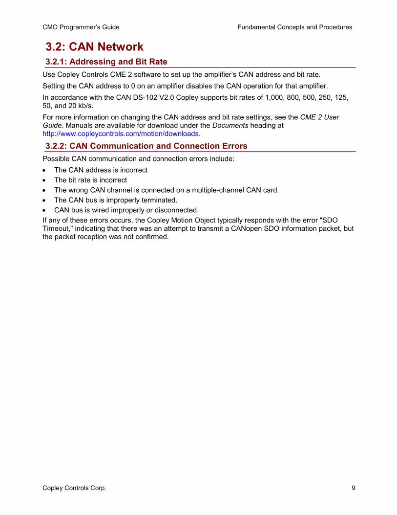
3.3.1: Adding a Reference to a Program in VB 3.3.1.1 In the project workspace menu, choose the add reference command.
For instance, in .NET 2005: ProjectAdd Reference to open the Add Reference window, then select the COM tab.
3.3.1.2 Scroll to highlight the entry for CMO Type Library.3.3.1.3 Click OK.
CMO Programmer’s Guide Fundamental Concepts and Procedures
Copley Controls Corp. 11
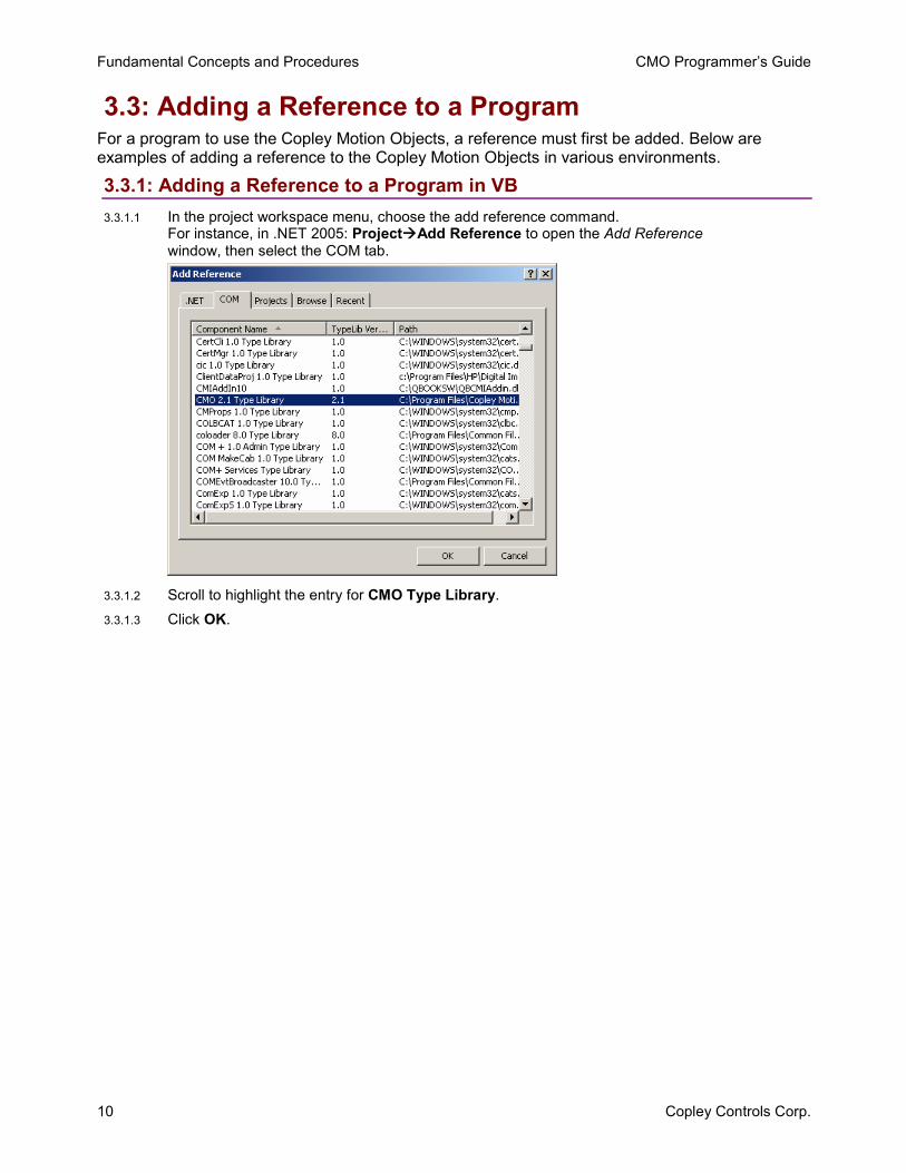
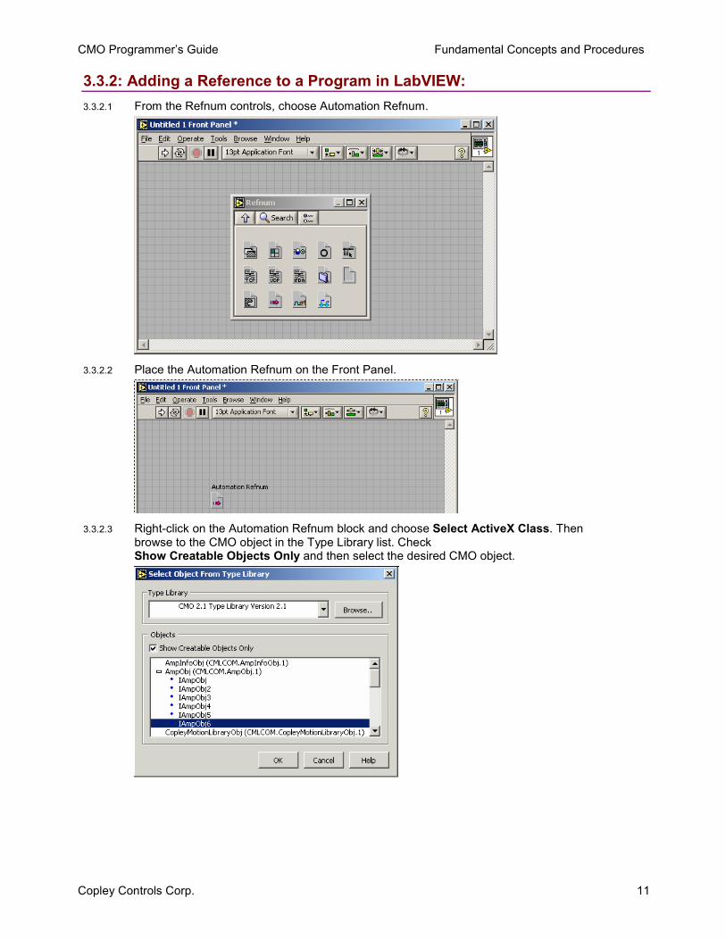
3.3.2: Adding a Reference to a Program in LabVIEW: 3.3.2.1 From the Refnum controls, choose Automation Refnum.
3.3.2.2 Place the Automation Refnum on the Front Panel.
3.3.2.3 Right-click on the Automation Refnum block and choose Select ActiveX Class. Then browse to the CMO object in the Type Library list. Check Show Creatable Objects Only and then select the desired CMO object.
Fundamental Concepts and Procedures CMO Programmer’s Guide
12 Copley Controls Corp.
3.4: Object Initialization Sequence 3.4.1: CAN Network, and Amplifier Objects
Every Copley Motion Objects application requires the creation and initialization of at least two basic objects: one to represent the network, and one to represent each amplifier. These objects should always be initialized in the following order: 1. CANopen network object: CANOpenObj. See the CANOpenObj method Initialize (p. 17). 2. Amplifier objects: AmpObj. See the AmpObj method Initialize (p. 21). Failure to follow this sequence will result in an error.
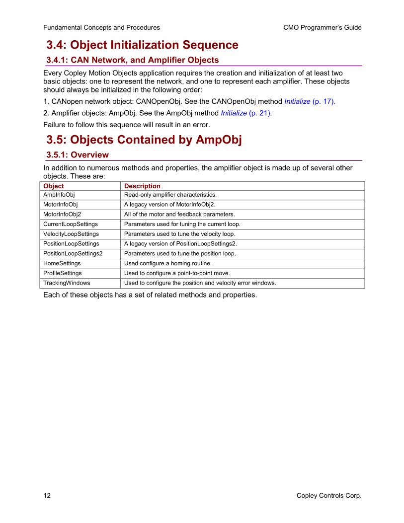
3.5: Objects Contained by AmpObj 3.5.1: Overview
In addition to numerous methods and properties, the amplifier object is made up of several other objects. These are: Object Description AmpInfoObj Read-only amplifier characteristics. MotorInfoObj A legacy version of MotorInfoObj2. MotorInfoObj2 All of the motor and feedback parameters. CurrentLoopSettings Parameters used for tuning the current loop. VelocityLoopSettings Parameters used to tune the velocity loop. PositionLoopSettings A legacy version of PositionLoopSettings2. PositionLoopSettings2 Parameters used to tune the position loop. HomeSettings Used configure a homing routine. ProfileSettings Used to configure a point-to-point move. TrackingWindows Used to configure the position and velocity error windows.
Each of these objects has a set of related methods and properties.
CMO Programmer’s Guide Fundamental Concepts and Procedures
Copley Controls Corp. 13
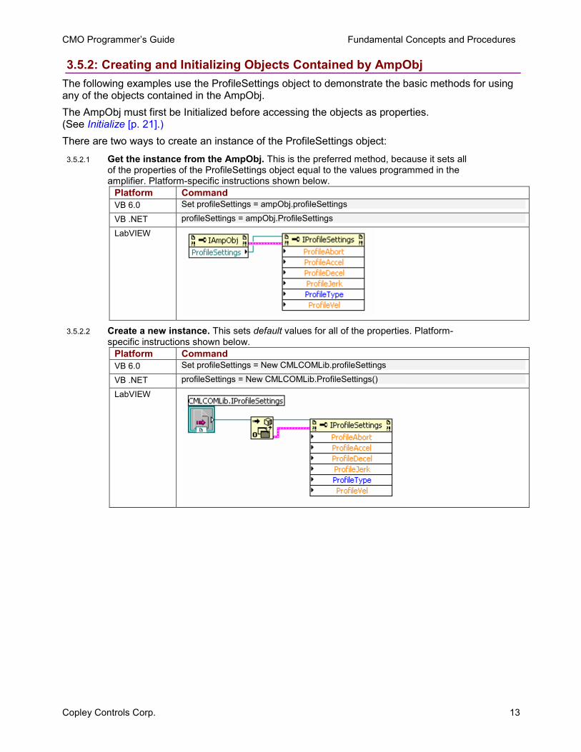
3.5.2: Creating and Initializing Objects Contained by AmpObj The following examples use the ProfileSettings object to demonstrate the basic methods for using any of the objects contained in the AmpObj. The AmpObj must first be Initialized before accessing the objects as properties. (See Initialize [p. 21].) There are two ways to create an instance of the ProfileSettings object:
3.5.2.1 Get the instance from the AmpObj. This is the preferred method, because it sets all of the properties of the ProfileSettings object equal to the values programmed in the amplifier. Platform-specific instructions shown below.
Platform Command VB 6.0 Set profileSettings = ampObj.profileSettings
VB .NET profileSettings = ampObj.ProfileSettings
LabVIEW
3.5.2.2 Create a new instance. This sets default values for all of the properties. Platform-specific instructions shown below.
Platform Command VB 6.0 Set profileSettings = New CMLCOMLib.profileSettings
VB .NET profileSettings = New CMLCOMLib.ProfileSettings()
LabVIEW
Fundamental Concepts and Procedures CMO Programmer’s Guide
14 Copley Controls Corp.
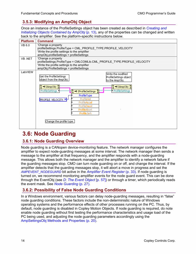
3.5.3: Modifying an AmpObj Object Once an instance of the ProfileSettings object has been created as described in Creating and Initializing Objects Contained by AmpObj (p. 13), any of the properties can be changed and written back to the amplifier. See the platform-specific instructions below. Platform Command VB 6.0 ‘Change a property
profileSettings.ProfileType = CML_PROFILE_TYPE.PROFILE_VELOCITY ‘Write the profile settings to the amplifier ampObj.profileSettings = profileSettings
VB .NET ‘Change a property profileSettings.ProfileType = CMLCOMLib.CML_PROFILE_TYPE.PROFILE_VELOCITY ‘Write the profile settings to the amplifier ampObj.ProfileSettings = profileSettings
LabVIEW
3.6: Node Guarding 3.6.1: Node Guarding Overview
Node guarding is a CANopen device-monitoring feature. The network manager configures the amplifier to expect node-guarding messages at some interval. The network manager then sends a message to the amplifier at that frequency, and the amplifier responds with a node-guarding message. This allows both the network manager and the amplifier to identify a network failure if the guarding messages stop. CMO can turn node guarding on or off, and change the interval. If the amplifier detects that the guarding messages stop, it will abort a move in progress and set the AMPEVENT_NODEGUARD bit active in the Amplifier Event Register (p. 33). If node guarding is turned on, we recommend monitoring amplifier events for the node guard event. This can be done through the EventObj (see D: The Event Object [p. 57]) or through a timer, which periodically reads the event mask. See Node Guarding (p. 27).
3.6.2: Possibility of False Node Guarding Conditions In a Windows environment, various factors can delay node-guarding messages, resulting in “false” node guarding conditions. These factors include the non-deterministic nature of Windows operating systems and the performance effects of other processes running on the PC. Thus, by default, node guarding is disabled in Copley Motion Objects. If node guarding is required, do note enable node guarding without first testing the performance characteristics and usage load of the PC being used, and adjusting the node guarding parameters accordingly using the AmpSettingsObj Methods and Properties (p. 20).
CMO Programmer’s Guide Fundamental Concepts and Procedures
Copley Controls Corp. 15
3.7: Error Handling Copley Motion Objects test for error conditions. If an error is present, Copley Motion Objects reports the error in the form of COM-compatible error objects. The error object includes a text description, error number, and the source of the error. For better error handling, each program should include error-handling procedures to guarantee that unexpected motion does not occur.
3.8: Units 3.8.1: Default Amplifier Units
The default Copley Motion Objects units are encoder counts. • Position or Distance: encoder counts • Velocity: 0.1 encoder counts per second • Acceleration: 10 encoder counts per second2
• Deceleration: 10 encoder counts per second2
• Jerk: 100 encoder counts per second3
3.8.2: User-Defined Units The Amplifier Object property CountsPerUnit (p. 49) can store a scaling factor for converting between an amplifier’s default units (encoder counts) and user-defined units. Default = 1. For example, with a 5-miron encoder on a linear motor, to program in millimeters, set CountsPerUnit = 200, since there are 200 encoder counts in one millimeter.
Fundamental Concepts and Procedures CMO Programmer’s Guide
16 Copley Controls Corp.
3.9: Stepnet Amplifiers 3.9.1: Stepper and Servo Modes
On power up/reset Stepnet amplifiers start in stepper mode. If it is necessary to switch a Stepnet amplifier from step to servo mode, set the property AmpMode (p. 49) to one of the servo modes listed in Modes of Operation for CML_AMP_MODE (p. 50). This should be done immediately after amplifier initialization. In the following example, the amplifier is initialized and then the amplifier’s mode of operation is switched to the servo Can profile mode:
ampObj.Initialize(canOpen, 1) ampObj.AmpModeWrite = CMLCOMLib.CML_AMP_MODE.AMPMODE_SERVO_CAN_PROFILE
3.9.2: Open Loop Stepper Mode Actual Position and Velocity When running open loop stepper mode, actual position and actual velocity readings remain at zero. The motor’s commanded position can be monitored with CMLCOMLib.AmpObj.PositionCommand (Units: microsteps). The motor’s commanded velocity can be monitored with CMLCOMLib AmpObj.TrajectoryVel (Units microsteps/second). When the amplifier is disabled, PositionCommand goes to zero because the amplifier cannot tell if the motor moves while disabled. As long as the amplifier is enabled, relative and absolute moves can be made based on PositionCommand.
3.9.3: Stepper Mode with Encoder Actual Position and Velocity When running in stepper mode with an encoder, actual position can be monitored with CMLCOMLib.AmpObj.PositionActual (Units: microsteps). Actual velocity can be monitored with CMLCOMLib.AmpObj.VelocityLoad (Units microsteps/second). NOTE: Actual velocity can also be monitored with CMLCOMLib.AmpObj.VelocityActual, but the units will be in encoder counts/second. This is not recommended, because user units will also be applied to this value.
Copley Controls Corp. 17
APPENDIX A: CANOPEN OBJECT
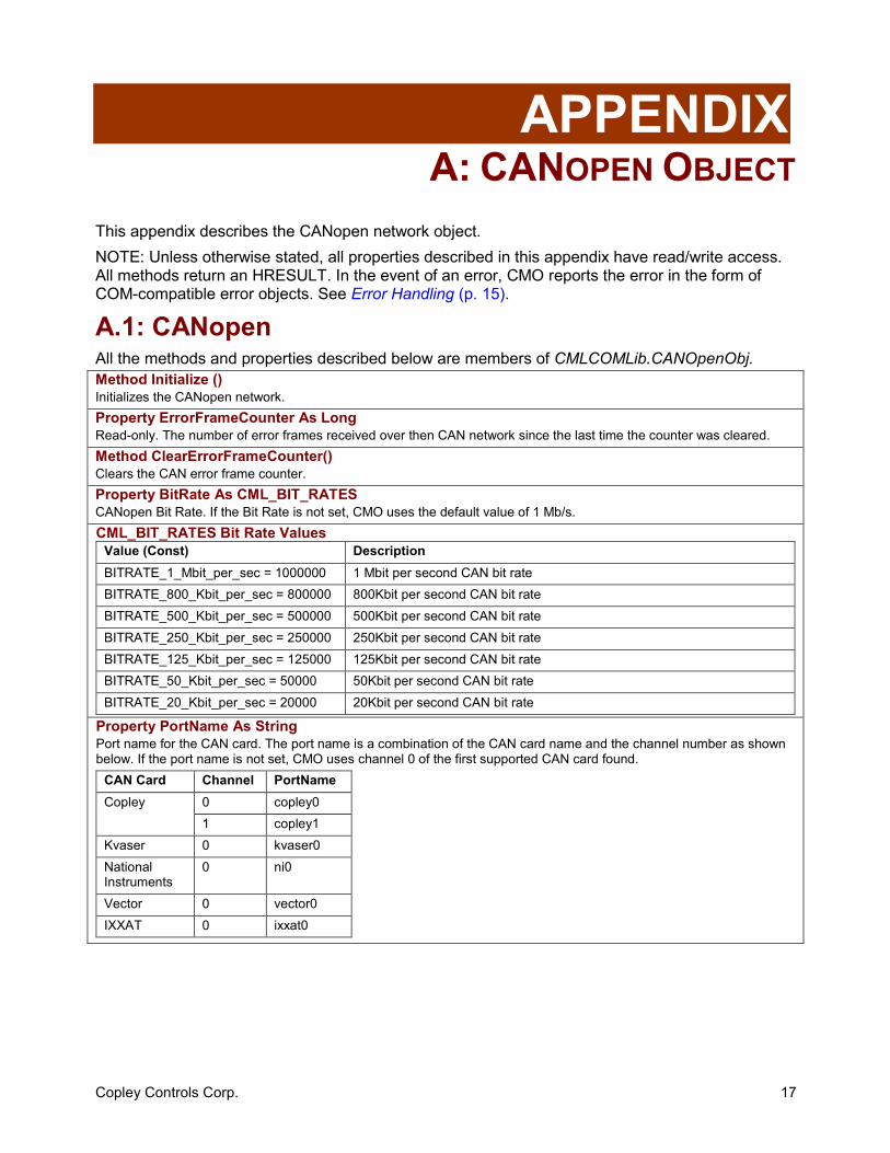
This appendix describes the CANopen network object. NOTE: Unless otherwise stated, all properties described in this appendix have read/write access. All methods return an HRESULT. In the event of an error, CMO reports the error in the form of COM-compatible error objects. See Error Handling (p. 15).
A.1: CANopen All the methods and properties described below are members of CMLCOMLib.CANOpenObj. Method Initialize () Initializes the CANopen network. Property ErrorFrameCounter As Long Read-only. The number of error frames received over then CAN network since the last time the counter was cleared. Method ClearErrorFrameCounter() Clears the CAN error frame counter. Property BitRate As CML_BIT_RATES CANopen Bit Rate. If the Bit Rate is not set, CMO uses the default value of 1 Mb/s. CML_BIT_RATES Bit Rate Values
Value (Const) Description BITRATE_1_Mbit_per_sec = 1000000 1 Mbit per second CAN bit rate BITRATE_800_Kbit_per_sec = 800000 800Kbit per second CAN bit rate BITRATE_500_Kbit_per_sec = 500000 500Kbit per second CAN bit rate BITRATE_250_Kbit_per_sec = 250000 250Kbit per second CAN bit rate BITRATE_125_Kbit_per_sec = 125000 125Kbit per second CAN bit rate BITRATE_50_Kbit_per_sec = 50000 50Kbit per second CAN bit rate BITRATE_20_Kbit_per_sec = 20000 20Kbit per second CAN bit rate
Property PortName As String Port name for the CAN card. The port name is a combination of the CAN card name and the channel number as shown below. If the port name is not set, CMO uses channel 0 of the first supported CAN card found.
CAN Card Channel PortName 0 copley0 Copley
1 copley1 Kvaser 0 kvaser0 National Instruments
0 ni0
Vector 0 vector0 IXXAT 0 ixxat0

A: CANopen Object CMO Programmer’s Guide
18 Copley Controls Corp.
Copley Controls Corp. 19
APPENDIX B: AMPLIFIER AND RELATED OBJECTS
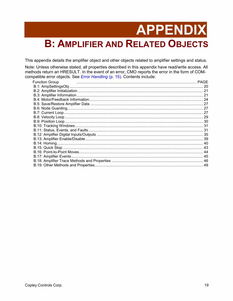
This appendix details the amplifier object and other objects related to amplifier settings and status. Note: Unless otherwise stated, all properties described in this appendix have read/write access. All methods return an HRESULT. In the event of an error, CMO reports the error in the form of COM-compatible error objects. See Error Handling (p. 15). Contents include:
Function Group .................................................................................................................. PAGE B.1: AmpSettingsObj ............................................................................................................................... 20 B.2: Amplifier Initialization ....................................................................................................................... 21 B.3: Amplifier Information ........................................................................................................................ 21 B.4: Motor/Feedback Information............................................................................................................ 24 B.5: Save/Restore Amplifier Data ........................................................................................................... 27 B.6: Node Guarding................................................................................................................................. 27 B.7: Current Loop .................................................................................................................................... 27 B.8: Velocity Loop ................................................................................................................................... 29 B.9: Position Loop ................................................................................................................................... 30 B.10: Tracking Windows.......................................................................................................................... 31 B.11: Status, Events, and Faults............................................................................................................. 31 B.12: Amplifier Digital Inputs/Outputs ..................................................................................................... 35 B.13: Amplifier Enable/Disable................................................................................................................ 39 B.14: Homing........................................................................................................................................... 40 B.15: Quick Stop ..................................................................................................................................... 43 B.16: Point-to-Point Moves...................................................................................................................... 44 B.17: Amplifier Events ............................................................................................................................. 45 B.18: Amplifier Trace Methods and Properties ....................................................................................... 46 B.19: Other Methods and Properties....................................................................................................... 49
B: Amplifier and Related Objects CMO Programmer’s Guide
20 Copley Controls Corp.
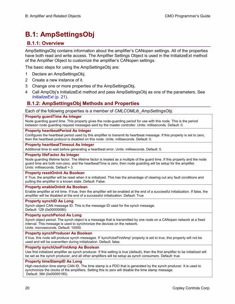
B.1: AmpSettingsObj B.1.1: Overview
AmpSettingsObj contains information about the amplifier’s CANopen settings. All of the properties have both read and write access. The Amplifier Settings Object is used in the InitializeExt method of the Amplifier Object to customize the amplifier’s CANopen settings. The basic steps for using the AmpSettingsObj are: 1 Declare an AmpSettingsObj. 2 Create a new instance of it. 3 Change one or more properties of the AmpSettingsObj. 4 Call AmpObj’s InitializeExt method and pass AmpSettingsObj as one of the parameters. See
InitializeExt (p. 21). B.1.2: AmpSettingsObj Methods and Properties
Each of the following properties is a member of CMLCOMLib_AmpSettingsObj.Property guardTime As Integer Node guarding guard time. This property gives the node-guarding period for use with this node. This is the period between node guarding request messages sent by the master controller. Units: milliseconds. Default: 0. Property heartbeatPeriod As Integer Configures the heartbeat period used by this amplifier to transmit its heartbeat message. If this property is set to zero, then the heartbeat protocol is disabled on this node. Units: milliseconds. Default: 0. Property heartbeatTimeout As Integer Additional time to wait before generating a heartbeat error. Units: milliseconds. Default: 0. Property lifeFactor As Integer Node guarding lifetime factor. The lifetime factor is treated as a multiple of the guard time. If this property and the node guard time are both non-zero, and the heartbeatTime is zero, then node guarding will be setup for the amplifier. Units: milliseconds. Default = 3. Property resetOnInit As Boolean If True, the amplifier will be reset when it is initialized. This has the advantage of clearing out any fault conditions and putting the amplifier in a known state. Default: False. Property enableOnInit As Boolean Enable amplifier at init time. If true, then the amplifier will be enabled at the end of a successful initialization. If false, the amplifier will be disabled at the end of a successful initialization. Default: True Property synchID As Long Synch object CAN message ID. This is the message ID used for the synch message. Default: 128 (0x00000080) Property synchPeriod As Long Synch object period. The synch object is a message that is transmitted by one node on a CANopen network at a fixed interval. This message is used to synchronize the devices on the network. Units: microseconds. Default: 10000. Property synchProducer As Boolean If true, this node will produce synch messages. If 'synchUseFirstAmp' property is set to true, this property will not be used and will be overwritten during initialization. Default: false. Property synchUseFirstAmp As Boolean Use first initialized amplifier as synch producer. If this setting is true (default), then the first amplifier to be initialized will be set as the synch producer, and all other amplifiers will be setup as synch consumers. Default: true Property timeStampID As Long High-resolution time stamp CAN ID. The time stamp is a PDO that is generated by the synch producer. It is used to synchronize the clocks of the amplifiers. Setting this to zero will disable the time stamp message. Default: 384 (0x00000180).
CMO Programmer’s Guide B: Amplifier and Related Objects
Copley Controls Corp. 21
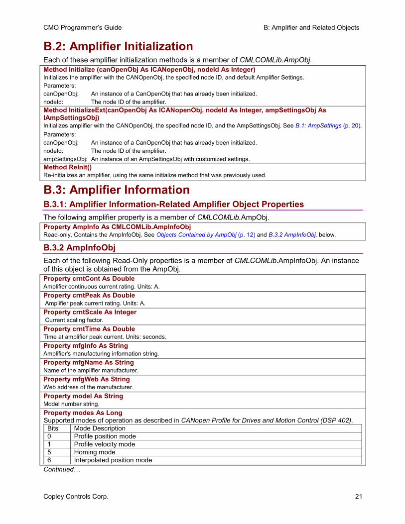
B.2: Amplifier Initialization Each of these amplifier initialization methods is a member of CMLCOMLib.AmpObj.Method Initialize (canOpenObj As ICANopenObj, nodeId As Integer) Initializes the amplifier with the CANOpenObj, the specified node ID, and default Amplifier Settings. Parameters: canOpenObj: An instance of a CanOpenObj that has already been initialized. nodeId: The node ID of the amplifier. Method InitializeExt(canOpenObj As ICANopenObj, nodeId As Integer, ampSettingsObj As IAmpSettingsObj) Initializes amplifier with the CANOpenObj, the specified node ID, and the AmpSettingsObj. See B.1: AmpSettings (p. 20).Parameters: canOpenObj: An instance of a CanOpenObj that has already been initialized. nodeId: The node ID of the amplifier. ampSettingsObj: An instance of an AmpSettingsObj with customized settings. Method ReInit() Re-initializes an amplifier, using the same initialize method that was previously used.
B.3: Amplifier Information B.3.1: Amplifier Information-Related Amplifier Object Properties The following amplifier property is a member of CMLCOMLib.AmpObj. Property AmpInfo As CMLCOMLib.AmpInfoObj Read-only. Contains the AmpInfoObj. See Objects Contained by AmpObj (p. 12) and B.3.2 AmpInfoObj, below.
B.3.2 AmpInfoObj Each of the following Read-Only properties is a member of CMLCOMLib.AmpInfoObj. An instance of this object is obtained from the AmpObj. Property crntCont As Double Amplifier continuous current rating. Units: A. Property crntPeak As Double Amplifier peak current rating. Units: A. Property crntScale As Integer Current scaling factor. Property crntTime As Double Time at amplifier peak current. Units: seconds. Property mfgInfo As String Amplifier's manufacturing information string. Property mfgName As String Name of the amplifier manufacturer. Property mfgWeb As String Web address of the manufacturer. Property model As String Model number string. Property modes As LongSupported modes of operation as described in CANopen Profile for Drives and Motion Control (DSP 402).
Bits Mode Description 0 Profile position mode 1 Profile velocity mode 5 Homing mode 6 Interpolated position mode
Continued…
B: Amplifier and Related Objects CMO Programmer’s Guide
22 Copley Controls Corp.
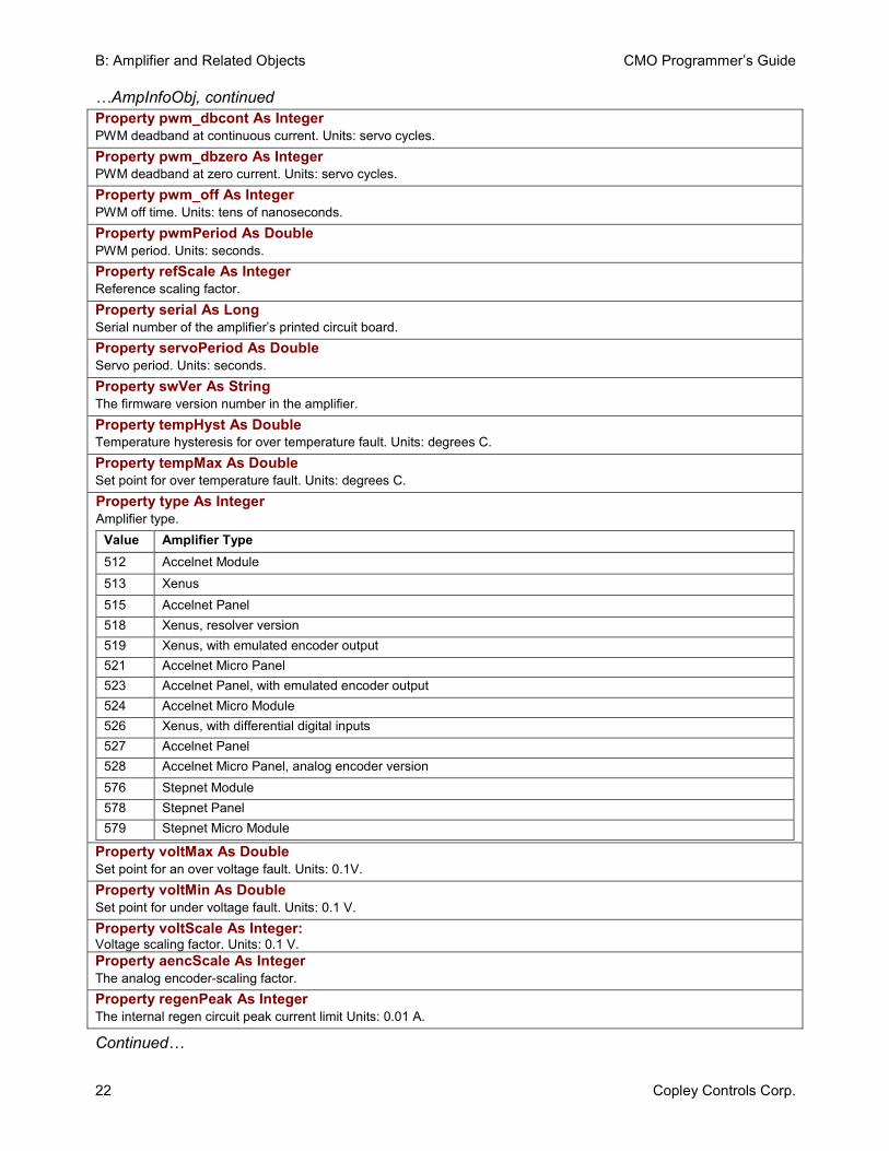
…AmpInfoObj, continued Property pwm_dbcont As Integer PWM deadband at continuous current. Units: servo cycles. Property pwm_dbzero As Integer PWM deadband at zero current. Units: servo cycles. Property pwm_off As Integer PWM off time. Units: tens of nanoseconds. Property pwmPeriod As Double PWM period. Units: seconds. Property refScale As Integer Reference scaling factor. Property serial As Long Serial number of the amplifier’s printed circuit board. Property servoPeriod As Double Servo period. Units: seconds. Property swVer As String The firmware version number in the amplifier. Property tempHyst As Double Temperature hysteresis for over temperature fault. Units: degrees C. Property tempMax As Double Set point for over temperature fault. Units: degrees C. Property type As IntegerAmplifier type.
Value Amplifier Type 512 Accelnet Module 513 Xenus 515 Accelnet Panel 518 Xenus, resolver version 519 Xenus, with emulated encoder output 521 Accelnet Micro Panel 523 Accelnet Panel, with emulated encoder output 524 Accelnet Micro Module 526 Xenus, with differential digital inputs 527 Accelnet Panel 528 Accelnet Micro Panel, analog encoder version 576 Stepnet Module 578 Stepnet Panel 579 Stepnet Micro Module
Property voltMax As Double Set point for an over voltage fault. Units: 0.1V. Property voltMin As Double Set point for under voltage fault. Units: 0.1 V. Property voltScale As Integer: Voltage scaling factor. Units: 0.1 V. Property aencScale As Integer The analog encoder-scaling factor. Property regenPeak As Integer The internal regen circuit peak current limit Units: 0.01 A.
Continued…
CMO Programmer’s Guide B: Amplifier and Related Objects
Copley Controls Corp. 23
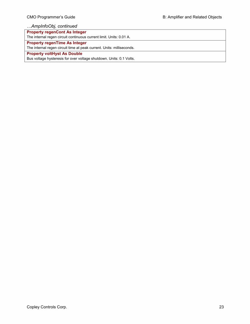
…AmpInfoObj, continued Property regenCont As Integer The internal regen circuit continuous current limit. Units: 0.01 A. Property regenTime As Integer The internal regen circuit time at peak current. Units: milliseconds. Property voltHyst As Double Bus voltage hysteresis for over voltage shutdown. Units: 0.1 Volts.
B: Amplifier and Related Objects CMO Programmer’s Guide
24 Copley Controls Corp.
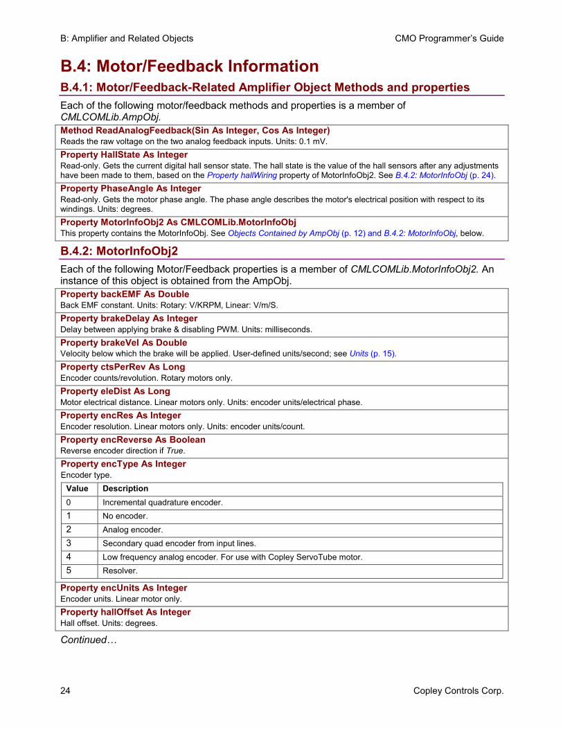
B.4: Motor/Feedback Information B.4.1: Motor/Feedback-Related Amplifier Object Methods and properties Each of the following motor/feedback methods and properties is a member of CMLCOMLib.AmpObj. Method ReadAnalogFeedback(Sin As Integer, Cos As Integer) Reads the raw voltage on the two analog feedback inputs. Units: 0.1 mV. Property HallState As Integer Read-only. Gets the current digital hall sensor state. The hall state is the value of the hall sensors after any adjustments have been made to them, based on the Property hallWiring property of MotorInfoObj2. See B.4.2: MotorInfoObj (p. 24). Property PhaseAngle As Integer Read-only. Gets the motor phase angle. The phase angle describes the motor's electrical position with respect to its windings. Units: degrees. Property MotorInfoObj2 As CMLCOMLib.MotorInfoObj This property contains the MotorInfoObj. See Objects Contained by AmpObj (p. 12) and B.4.2: MotorInfoObj, below.
B.4.2: MotorInfoObj2 Each of the following Motor/Feedback properties is a member of CMLCOMLib.MotorInfoObj2. An instance of this object is obtained from the AmpObj. Property backEMF As Double Back EMF constant. Units: Rotary: V/KRPM, Linear: V/m/S. Property brakeDelay As Integer Delay between applying brake & disabling PWM. Units: milliseconds. Property brakeVel As Double Velocity below which the brake will be applied. User-defined units/second; see Units (p. 15). Property ctsPerRev As Long Encoder counts/revolution. Rotary motors only. Property eleDist As Long Motor electrical distance. Linear motors only. Units: encoder units/electrical phase. Property encRes As Integer Encoder resolution. Linear motors only. Units: encoder units/count. Property encReverse As Boolean Reverse encoder direction if True.Property encType As Integer Encoder type.
Value Description 0 Incremental quadrature encoder. 1 No encoder. 2 Analog encoder. 3 Secondary quad encoder from input lines. 4 Low frequency analog encoder. For use with Copley ServoTube motor. 5 Resolver.
Property encUnits As Integer Encoder units. Linear motor only. Property hallOffset As Integer Hall offset. Units: degrees.
Continued…
CMO Programmer’s Guide B: Amplifier and Related Objects
Copley Controls Corp. 25
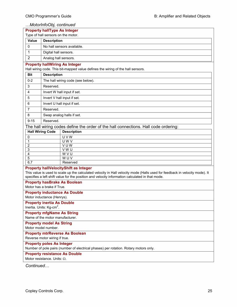
…MotorInfoObj, continued Property hallType As IntegerType of hall sensors on the motor.
Value Description 0 No hall sensors available. 1 Digital hall sensors. 2 Analog hall sensors.
Property hallWiring As IntegerHall wiring code. This bit-mapped value defines the wiring of the hall sensors.
Bit Description 0-2 The hall wiring code (see below). 3 Reserved. 4 Invert W hall input if set. 5 Invert V hall input if set. 6 Invert U hall input if set. 7 Reserved. 8 Swap analog halls if set. 9-15 Reserved.
The hall wiring codes define the order of the hall connections. Hall code ordering: Hall Wiring Code Description 0 U V W1 U W V2 V U W3 V W U4 W V U5 W U V6,7 Reserved
Property hallVelocityShift as Integer This value is used to scale up the calculated velocity in Hall velocity mode (Halls used for feedback in velocity mode). It specifies a left shift value for the position and velocity information calculated in that mode. Property hasBrake As Boolean Motor has a brake if True. Property inductance As Double Motor inductance (Henrys). Property inertia As Double Inertia. Units: Kg-cm2.Property mfgName As String Name of the motor manufacturer. Property model As String Motor model number. Property mtrReverse As Boolean Reverse motor wiring if true. Property poles As Integer Number of pole pairs (number of electrical phases) per rotation. Rotary motors only. Property resistance As Double Motor resistance. Units: Ω.
Continued…
B: Amplifier and Related Objects CMO Programmer’s Guide
26 Copley Controls Corp.
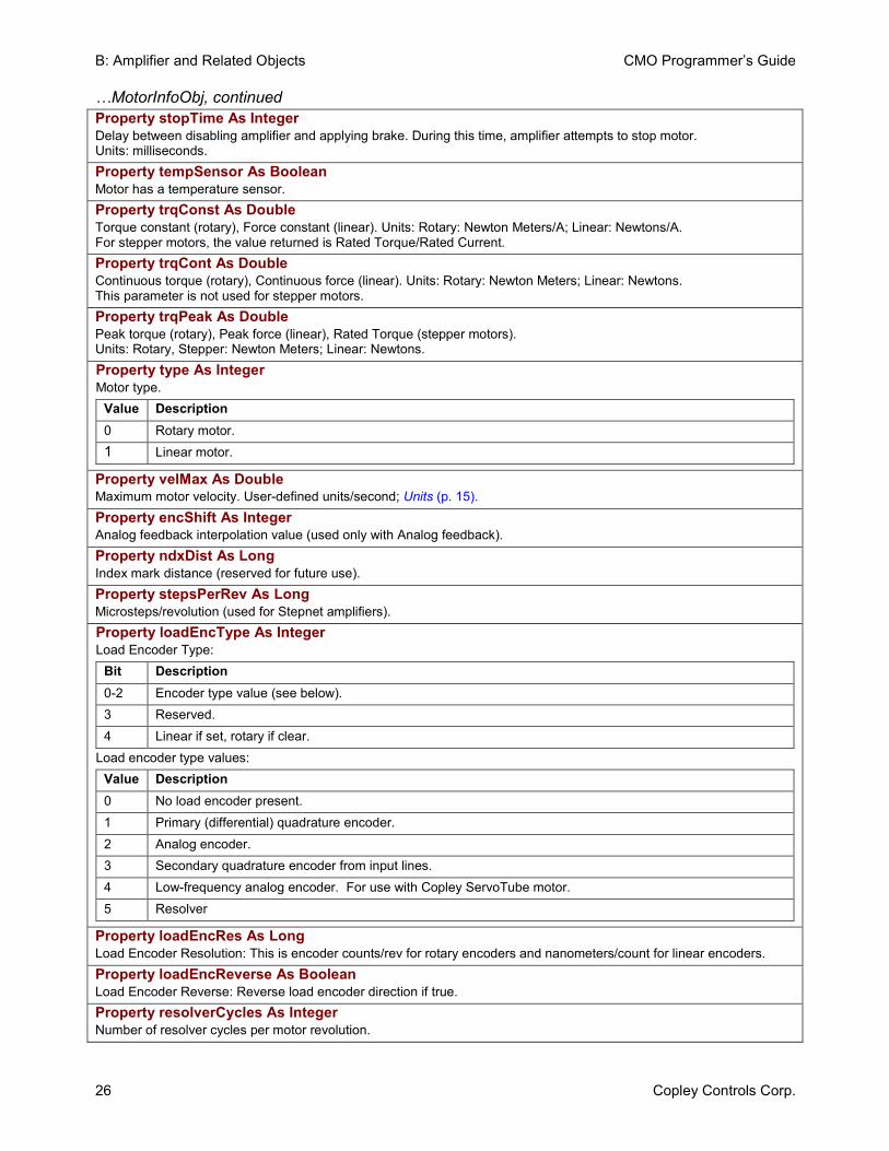
…MotorInfoObj, continued Property stopTime As Integer Delay between disabling amplifier and applying brake. During this time, amplifier attempts to stop motor. Units: milliseconds. Property tempSensor As Boolean Motor has a temperature sensor. Property trqConst As Double Torque constant (rotary), Force constant (linear). Units: Rotary: Newton Meters/A; Linear: Newtons/A. For stepper motors, the value returned is Rated Torque/Rated Current. Property trqCont As Double Continuous torque (rotary), Continuous force (linear). Units: Rotary: Newton Meters; Linear: Newtons. This parameter is not used for stepper motors. Property trqPeak As Double Peak torque (rotary), Peak force (linear), Rated Torque (stepper motors). Units: Rotary, Stepper: Newton Meters; Linear: Newtons. Property type As Integer Motor type.
Value Description 0 Rotary motor. 1 Linear motor.
Property velMax As Double Maximum motor velocity. User-defined units/second; Units (p. 15). Property encShift As Integer Analog feedback interpolation value (used only with Analog feedback). Property ndxDist As Long Index mark distance (reserved for future use). Property stepsPerRev As Long Microsteps/revolution (used for Stepnet amplifiers). Property loadEncType As Integer Load Encoder Type:
Bit Description 0-2 Encoder type value (see below). 3 Reserved. 4 Linear if set, rotary if clear.
Load encoder type values: Value Description 0 No load encoder present. 1 Primary (differential) quadrature encoder. 2 Analog encoder. 3 Secondary quadrature encoder from input lines. 4 Low-frequency analog encoder. For use with Copley ServoTube motor. 5 Resolver
Property loadEncRes As Long Load Encoder Resolution: This is encoder counts/rev for rotary encoders and nanometers/count for linear encoders. Property loadEncReverse As Boolean Load Encoder Reverse: Reverse load encoder direction if true. Property resolverCycles As Integer Number of resolver cycles per motor revolution.
CMO Programmer’s Guide B: Amplifier and Related Objects
Copley Controls Corp. 27
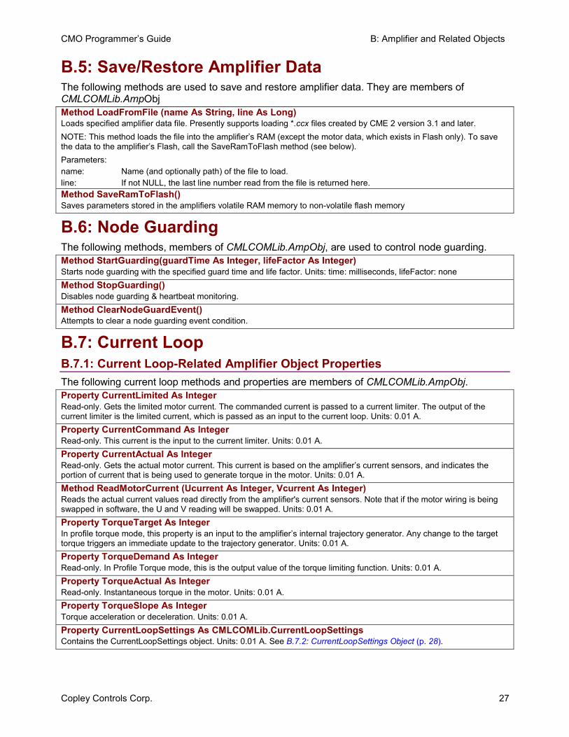
B.5: Save/Restore Amplifier Data The following methods are used to save and restore amplifier data. They are members of CMLCOMLib.AmpObj Method LoadFromFile (name As String, line As Long) Loads specified amplifier data file. Presently supports loading *.ccx files created by CME 2 version 3.1 and later. NOTE: This method loads the file into the amplifier’s RAM (except the motor data, which exists in Flash only). To save the data to the amplifier’s Flash, call the SaveRamToFlash method (see below). Parameters: name: Name (and optionally path) of the file to load. line: If not NULL, the last line number read from the file is returned here. Method SaveRamToFlash() Saves parameters stored in the amplifiers volatile RAM memory to non-volatile flash memory
B.6: Node Guarding The following methods, members of CMLCOMLib.AmpObj, are used to control node guarding. Method StartGuarding(guardTime As Integer, lifeFactor As Integer) Starts node guarding with the specified guard time and life factor. Units: time: milliseconds, lifeFactor: none Method StopGuarding() Disables node guarding & heartbeat monitoring. Method ClearNodeGuardEvent() Attempts to clear a node guarding event condition.
B.7: Current Loop B.7.1: Current Loop-Related Amplifier Object Properties The following current loop methods and properties are members of CMLCOMLib.AmpObj.Property CurrentLimited As Integer Read-only. Gets the limited motor current. The commanded current is passed to a current limiter. The output of the current limiter is the limited current, which is passed as an input to the current loop. Units: 0.01 A. Property CurrentCommand As Integer Read-only. This current is the input to the current limiter. Units: 0.01 A. Property CurrentActual As Integer Read-only. Gets the actual motor current. This current is based on the amplifier’s current sensors, and indicates the portion of current that is being used to generate torque in the motor. Units: 0.01 A. Method ReadMotorCurrent (Ucurrent As Integer, Vcurrent As Integer) Reads the actual current values read directly from the amplifier's current sensors. Note that if the motor wiring is being swapped in software, the U and V reading will be swapped. Units: 0.01 A. Property TorqueTarget As Integer In profile torque mode, this property is an input to the amplifier’s internal trajectory generator. Any change to the target torque triggers an immediate update to the trajectory generator. Units: 0.01 A. Property TorqueDemand As Integer Read-only. In Profile Torque mode, this is the output value of the torque limiting function. Units: 0.01 A. Property TorqueActual As Integer Read-only. Instantaneous torque in the motor. Units: 0.01 A. Property TorqueSlope As Integer Torque acceleration or deceleration. Units: 0.01 A. Property CurrentLoopSettings As CMLCOMLib.CurrentLoopSettings Contains the CurrentLoopSettings object. Units: 0.01 A. See B.7.2: CurrentLoopSettings Object (p. 28).
B: Amplifier and Related Objects CMO Programmer’s Guide
28 Copley Controls Corp.
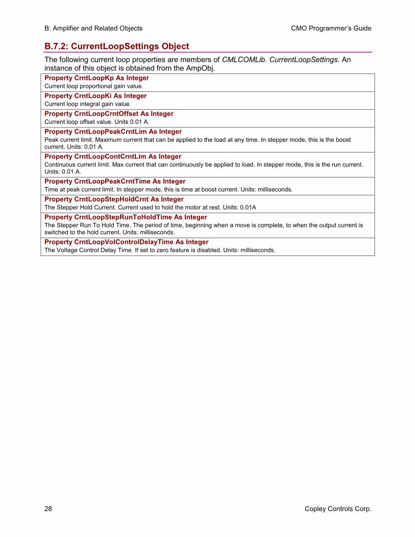
B.7.2: CurrentLoopSettings Object The following current loop properties are members of CMLCOMLib. CurrentLoopSettings. An instance of this object is obtained from the AmpObj. Property CrntLoopKp As Integer Current loop proportional gain value. Property CrntLoopKi As Integer Current loop integral gain value. Property CrntLoopCrntOffset As Integer Current loop offset value. Units 0.01 A. Property CrntLoopPeakCrntLim As Integer Peak current limit. Maximum current that can be applied to the load at any time. In stepper mode, this is the boost current. Units: 0.01 A. Property CrntLoopContCrntLim As Integer Continuous current limit. Max current that can continuously be applied to load. In stepper mode, this is the run current. Units: 0.01 A. Property CrntLoopPeakCrntTime As Integer Time at peak current limit. In stepper mode, this is time at boost current. Units: milliseconds. Property CrntLoopStepHoldCrnt As Integer The Stepper Hold Current. Current used to hold the motor at rest. Units: 0.01A Property CrntLoopStepRunToHoldTime As Integer The Stepper Run To Hold Time. The period of time, beginning when a move is complete, to when the output current is switched to the hold current. Units: milliseconds. Property CrntLoopVolControlDelayTime As Integer The Voltage Control Delay Time. If set to zero feature is disabled. Units: milliseconds.
CMO Programmer’s Guide B: Amplifier and Related Objects
Copley Controls Corp. 29
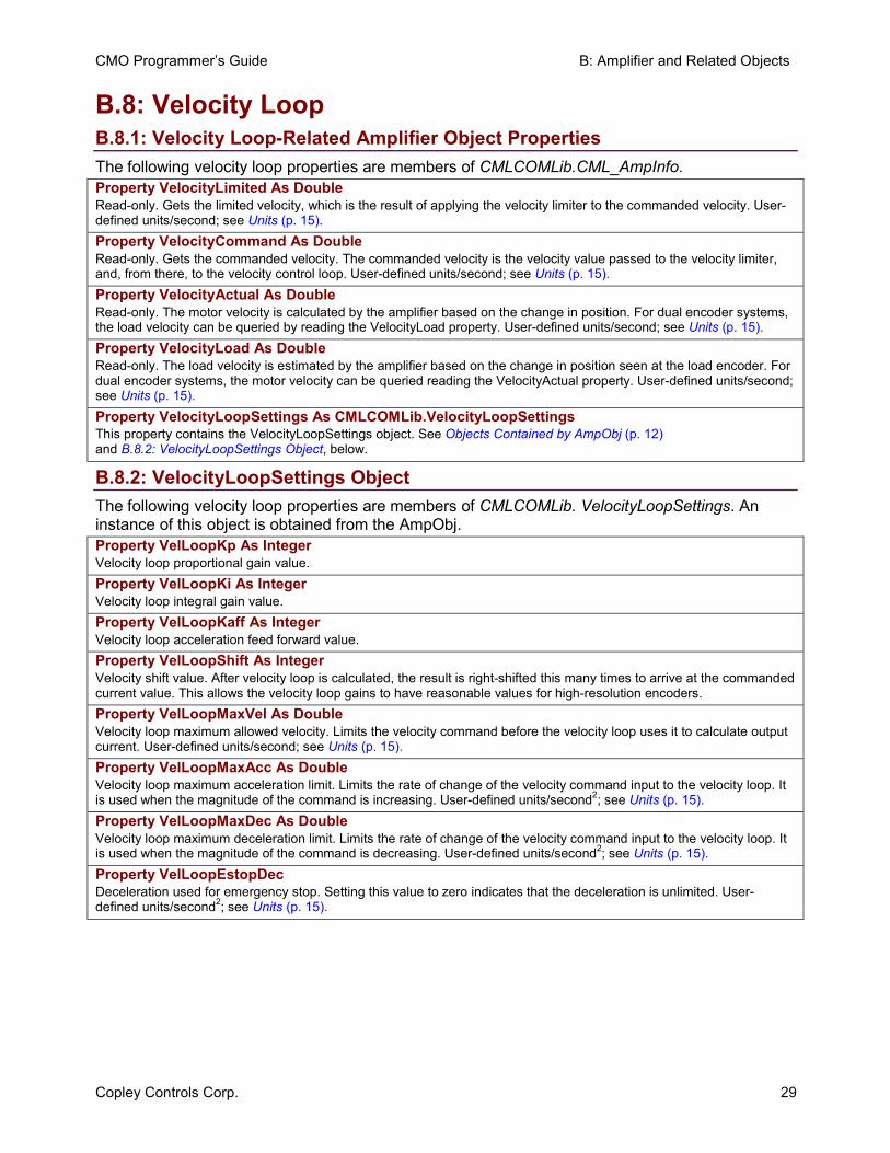
B.8: Velocity Loop B.8.1: Velocity Loop-Related Amplifier Object Properties The following velocity loop properties are members of CMLCOMLib.CML_AmpInfo.Property VelocityLimited As Double Read-only. Gets the limited velocity, which is the result of applying the velocity limiter to the commanded velocity. User-defined units/second; see Units (p. 15). Property VelocityCommand As Double Read-only. Gets the commanded velocity. The commanded velocity is the velocity value passed to the velocity limiter, and, from there, to the velocity control loop. User-defined units/second; see Units (p. 15). Property VelocityActual As Double Read-only. The motor velocity is calculated by the amplifier based on the change in position. For dual encoder systems, the load velocity can be queried by reading the VelocityLoad property. User-defined units/second; see Units (p. 15). Property VelocityLoad As Double Read-only. The load velocity is estimated by the amplifier based on the change in position seen at the load encoder. For dual encoder systems, the motor velocity can be queried reading the VelocityActual property. User-defined units/second; see Units (p. 15). Property VelocityLoopSettings As CMLCOMLib.VelocityLoopSettings This property contains the VelocityLoopSettings object. See Objects Contained by AmpObj (p. 12) and B.8.2: VelocityLoopSettings Object, below.
B.8.2: VelocityLoopSettings Object The following velocity loop properties are members of CMLCOMLib. VelocityLoopSettings. An instance of this object is obtained from the AmpObj. Property VelLoopKp As Integer Velocity loop proportional gain value. Property VelLoopKi As Integer Velocity loop integral gain value. Property VelLoopKaff As Integer Velocity loop acceleration feed forward value. Property VelLoopShift As Integer Velocity shift value. After velocity loop is calculated, the result is right-shifted this many times to arrive at the commanded current value. This allows the velocity loop gains to have reasonable values for high-resolution encoders. Property VelLoopMaxVel As Double Velocity loop maximum allowed velocity. Limits the velocity command before the velocity loop uses it to calculate output current. User-defined units/second; see Units (p. 15). Property VelLoopMaxAcc As Double Velocity loop maximum acceleration limit. Limits the rate of change of the velocity command input to the velocity loop. It is used when the magnitude of the command is increasing. User-defined units/second2; see Units (p. 15). Property VelLoopMaxDec As Double Velocity loop maximum deceleration limit. Limits the rate of change of the velocity command input to the velocity loop. It is used when the magnitude of the command is decreasing. User-defined units/second2; see Units (p. 15). Property VelLoopEstopDec Deceleration used for emergency stop. Setting this value to zero indicates that the deceleration is unlimited. User-defined units/second2; see Units (p. 15).
B: Amplifier and Related Objects CMO Programmer’s Guide
30 Copley Controls Corp.
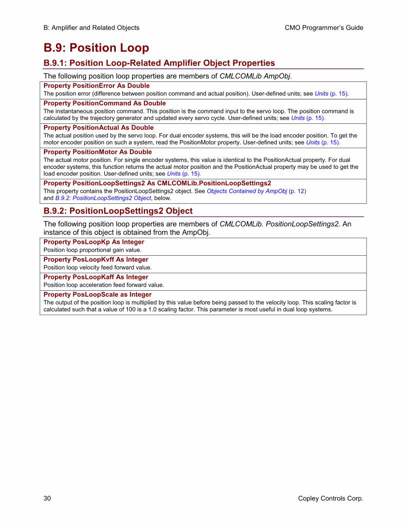
B.9: Position Loop B.9.1: Position Loop-Related Amplifier Object Properties The following position loop properties are members of CMLCOMLib AmpObj.Property PositionError As Double The position error (difference between position command and actual position). User-defined units; see Units (p. 15). Property PositionCommand As Double The instantaneous position command. This position is the command input to the servo loop. The position command is calculated by the trajectory generator and updated every servo cycle. User-defined units; see Units (p. 15). Property PositionActual As Double The actual position used by the servo loop. For dual encoder systems, this will be the load encoder position. To get the motor encoder position on such a system, read the PositionMotor property. User-defined units; see Units (p. 15). Property PositionMotor As Double The actual motor position. For single encoder systems, this value is identical to the PositionActual property. For dual encoder systems, this function returns the actual motor position and the PositionActual property may be used to get the load encoder position. User-defined units; see Units (p. 15). Property PositionLoopSettings2 As CMLCOMLib.PositionLoopSettings2 This property contains the PositionLoopSettings2 object. See Objects Contained by AmpObj (p. 12) and B.9.2: PositionLoopSettings2 Object, below.
B.9.2: PositionLoopSettings2 Object The following position loop properties are members of CMLCOMLib. PositionLoopSettings2. An instance of this object is obtained from the AmpObj. Property PosLoopKp As Integer Position loop proportional gain value. Property PosLoopKvff As Integer Position loop velocity feed forward value. Property PosLoopKaff As Integer Position loop acceleration feed forward value. Property PosLoopScale as Integer The output of the position loop is multiplied by this value before being passed to the velocity loop. This scaling factor is calculated such that a value of 100 is a 1.0 scaling factor. This parameter is most useful in dual loop systems.
CMO Programmer’s Guide B: Amplifier and Related Objects
Copley Controls Corp. 31
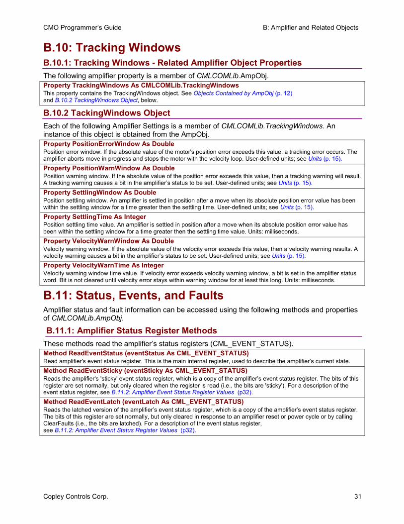
B.10: Tracking Windows B.10.1: Tracking Windows - Related Amplifier Object Properties The following amplifier property is a member of CMLCOMLib.AmpObj. Property TrackingWindows As CMLCOMLib.TrackingWindows This property contains the TrackingWindows object. See Objects Contained by AmpObj (p. 12) and B.10.2 TackingWindows Object, below.
B.10.2 TackingWindows Object Each of the following Amplifier Settings is a member of CMLCOMLib.TrackingWindows. An instance of this object is obtained from the AmpObj. Property PositionErrorWindow As Double Position error window. If the absolute value of the motor's position error exceeds this value, a tracking error occurs. The amplifier aborts move in progress and stops the motor with the velocity loop. User-defined units; see Units (p. 15). Property PositionWarnWindow As Double Position warning window. If the absolute value of the position error exceeds this value, then a tracking warning will result. A tracking warning causes a bit in the amplifier’s status to be set. User-defined units; see Units (p. 15). Property SettlingWindow As Double Position settling window. An amplifier is settled in position after a move when its absolute position error value has been within the settling window for a time greater then the settling time. User-defined units; see Units (p. 15). Property SettlingTime As Integer Position settling time value. An amplifier is settled in position after a move when its absolute position error value has been within the settling window for a time greater then the settling time value. Units: milliseconds. Property VelocityWarnWindow As Double Velocity warning window. If the absolute value of the velocity error exceeds this value, then a velocity warning results. A velocity warning causes a bit in the amplifier’s status to be set. User-defined units; see Units (p. 15). Property VelocityWarnTime As Integer Velocity warning window time value. If velocity error exceeds velocity warning window, a bit is set in the amplifier status word. Bit is not cleared until velocity error stays within warning window for at least this long. Units: milliseconds.
B.11: Status, Events, and Faults Amplifier status and fault information can be accessed using the following methods and properties of CMLCOMLib.AmpObj.
B.11.1: Amplifier Status Register Methods These methods read the amplifier’s status registers (CML_EVENT_STATUS). Method ReadEventStatus (eventStatus As CML_EVENT_STATUS) Read amplifier's event status register. This is the main internal register, used to describe the amplifier’s current state. Method ReadEventSticky (eventSticky As CML_EVENT_STATUS) Reads the amplifier's 'sticky' event status register, which is a copy of the amplifier’s event status register. The bits of this register are set normally, but only cleared when the register is read (i.e., the bits are 'sticky'). For a description of the event status register, see B.11.2: Amplifier Event Status Register Values (p32). Method ReadEventLatch (eventLatch As CML_EVENT_STATUS) Reads the latched version of the amplifier’s event status register, which is a copy of the amplifier’s event status register. The bits of this register are set normally, but only cleared in response to an amplifier reset or power cycle or by calling ClearFaults (i.e., the bits are latched). For a description of the event status register, see B.11.2: Amplifier Event Status Register Values (p32).
B: Amplifier and Related Objects CMO Programmer’s Guide
32 Copley Controls Corp.
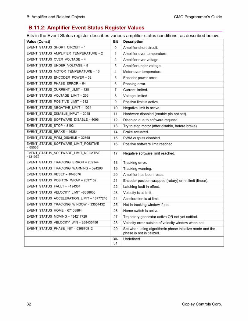
B.11.2: Amplifier Event Status Register Values Bits in the Event Status register describes various amplifier status conditions, as described below. Value (Const) Bit Description EVENT_STATUS_SHORT_CIRCUIT = 1 0 Amplifier short circuit. EVENT_STATUS_AMPLIFIER_TEMPERATURE = 2 1 Amplifier over temperature. EVENT_STATUS_OVER_VOLTAGE = 4 2 Amplifier over voltage. EVENT_STATUS_UNDER_VOLTAGE = 8 3 Amplifier under voltage. EVENT_STATUS_MOTOR_TEMPERATURE = 16 4 Motor over temperature. EVENT_STATUS_ENCODER_POWER = 32 5 Encoder power error. EVENT_STATUS_PHASE_ERROR = 64 6 Phasing error. EVENT_STATUS_CURRENT_LIMIT = 128 7 Current limited. EVENT_STATUS_VOLTAGE_LIMIT = 256 8 Voltage limited. EVENT_STATUS_POSITIVE_LIMIT = 512 9 Positive limit is active. EVENT_STATUS_NEGATIVE_LIMIT = 1024 10 Negative limit is active. EVENT_STATUS_DISABLE_INPUT = 2048 11 Hardware disabled (enable pin not set). EVENT_STATUS_SOFTWARE_DISABLE = 4096 12 Disabled due to software request. EVENT_STATUS_STOP = 8192 13 Try to stop motor (after disable, before brake). EVENT_STATUS_BRAKE = 16384 14 Brake actuated. EVENT_STATUS_PWM_DISABLE = 32768 15 PWM outputs disabled. EVENT_STATUS_SOFTWARE_LIMIT_POSITIVE = 65536
16 Positive software limit reached.
EVENT_STATUS_SOFTWARE_LIMIT_NEGATIVE =131072
17 Negative software limit reached.
EVENT_STATUS_TRACKING_ERROR = 262144 18 Tracking error. EVENT_STATUS_TRACKING_WARNING = 524288 19 Tracking warning. EVENT_STATUS_RESET = 1048576 20 Amplifier has been reset. EVENT_STATUS_POSITON_WRAP = 2097152 21 Encoder position wrapped (rotary) or hit limit (linear). EVENT_STATUS_FAULT = 4194304 22 Latching fault in effect. EVENT_STATUS_VELOCITY_LIMIT =8388608 23 Velocity is at limit. EVENT_STATUS_ACCELERATION_LIMIT = 16777216 24 Acceleration is at limit. EVENT_STATUS_TRACKING_WINDOW = 33554432 25 Not in tracking window if set. EVENT_STATUS_HOME = 67108864 26 Home switch is active. EVENT_STATUS_MOVING = 134217728 27 Trajectory generator active OR not yet settled. EVENT_STATUS_VELOCITY_WIN = 268435456 28 Velocity error outside of velocity window when set. EVENT_STATUS_PHASE_INIT = 536870912 29 Set when using algorithmic phase initialize mode and the
phase is not initialized. 30-31
Undefined
CMO Programmer’s Guide B: Amplifier and Related Objects
Copley Controls Corp. 33
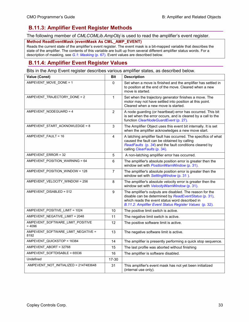
B.11.3: Amplifier Event Register Methods The following member of CMLCOMLib.AmpObj is used to read the amplifier’s event register. Method ReadEventMask (eventMask As CML_AMP_EVENT) Reads the current state of the amplifier’s event register. The event mask is a bit-mapped variable that describes the state of the amplifier. The contents of this variable are built up from several different amplifier status words. For a description of masking, see G.1: Masking (p. 67). Event values are described below.
B.11.4: Amplifier Event Register Values Bits in the Amp Event register describes various amplifier states, as described below. Value (Const) Bit Description AMPEVENT_MOVE_DONE = 1 0 Set when a move is finished and the amplifier has settled in
to position at the end of the move. Cleared when a new move is started.
AMPEVENT_TRAJECTORY_DONE = 2 1 Set when the trajectory generator finishes a move. The motor may not have settled into position at this point. Cleared when a new move is started.
AMPEVENT_NODEGUARD = 4 2 A node guarding (or heartbeat) error has occurred. This bit is set when the error occurs, and is cleared by a call to the function ClearNodeGuardEvent (p. 27).
AMPEVENT_START_ACKNOWLEDGE = 8 3 The Amplifier Object uses this event bit internally. It is set when the amplifier acknowledges a new move start.
AMPEVENT_FAULT = 16 4 A latching amplifier fault has occurred. The specifics of what caused the fault can be obtained by calling ReadFaults (p. 34) and the fault conditions cleared by calling ClearFaults (p. 34).
AMPEVENT_ERROR = 32 5 A non-latching amplifier error has occurred. AMPEVENT_POSITION_WARNING = 64 6 The amplifier's absolute position error is greater then the
window set with PositionWarnWindow (p. 31). AMPEVENT_POSITION_WINDOW = 128 7 The amplifier's absolute position error is greater then the
window set with SettlingWindow (p. 31 ). AMPEVENT_VELOCITY_WINDOW = 256 8 The amplifier's absolute velocity error is greater then the
window set with VelocityWarnWindow (p. 31). AMPEVENT_DISABLED = 512 9 The amplifier's outputs are disabled. The reason for the
disable can be determined by ReadEventStatus (p. 31),which reads the event status word described in B.11.2: Amplifier Event Status Register Values (p. 32).
AMPEVENT_POSITIVE_LIMIT = 1024 10 The positive limit switch is active. AMPEVENT_NEGATIVE_LIMIT = 2048 11 The negative limit switch is active. AMPEVENT_SOFTWARE_LIMIT_POSITIVE = 4096
12 The positive software limit is active.
AMPEVENT_SOFTWARE_LIMIT_NEGATIVE = 8192
13 The negative software limit is active.
AMPEVENT_QUICKSTOP = 16384 14 The amplifier is presently performing a quick stop sequence. AMPEVENT_ABORT = 32768 15 The last profile was aborted without finishing AMPEVENT_SOFTDISABLE = 65536 16 The amplifier is software disabled. Undefined 17-30 AMPEVENT_NOT_INITIALIZED = 2147483648 31 This amplifier's event mask has not yet been initialized
(internal use only).
B: Amplifier and Related Objects CMO Programmer’s Guide
34 Copley Controls Corp.
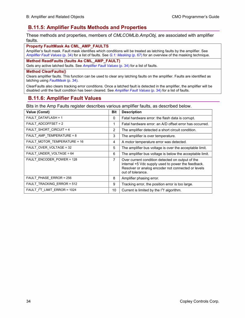
B.11.5: Amplifier Faults Methods and Properties These methods and properties, members of CMLCOMLib.AmpObj, are associated with amplifier faults. Property FaultMask As CML_AMP_FAULTS Amplifier’s fault mask. Fault mask identifies which conditions will be treated as latching faults by the amplifier. See Amplifier Fault Values (p. 34) for a list of faults. See G.1: Masking (p. 67) for an overview of the masking technique. Method ReadFaults (faults As CML_AMP_FAULT) Gets any active latched faults. See Amplifier Fault Values (p. 34) for a list of faults. Method ClearFaults() Clears amplifier faults. This function can be used to clear any latching faults on the amplifier. Faults are identified as latching using FaultMask (p. 34).ClearFaults also clears tracking error conditions. Once a latched fault is detected in the amplifier, the amplifier will be disabled until the fault condition has been cleared. See Amplifier Fault Values (p. 34) for a list of faults.
B.11.6: Amplifier Fault Values Bits in the Amp Faults register describes various amplifier faults, as described below. Value (Const) Bit Description FAULT_DATAFLASH = 1 0 Fatal hardware error: the flash data is corrupt. FAULT_ADCOFFSET = 2 1 Fatal hardware error: an A/D offset error has occurred. FAULT_SHORT_CIRCUIT = 4 2 The amplifier detected a short circuit condition. FAULT_AMP_TEMPERATURE = 8 3 The amplifier is over temperature. FAULT_MOTOR_TEMPERATURE = 16 4 A motor temperature error was detected. FAULT_OVER_VOLTAGE = 32 5 The amplifier bus voltage is over the acceptable limit. FAULT_UNDER_VOLTAGE = 64 6 The amplifier bus voltage is below the acceptable limit. FAULT_ENCODER_POWER = 128 7 Over current condition detected on output of the
internal +5 Vdc supply used to power the feedback. Resolver or analog encoder not connected or levels out of tolerance.
FAULT_PHASE_ERROR = 256 8 Amplifier phasing error. FAULT_TRACKING_ERROR = 512 9 Tracking error, the position error is too large. FAULT_I2T_LIMIT_ERROR = 1024 10 Current is limited by the I2T algorithm.
CMO Programmer’s Guide B: Amplifier and Related Objects
Copley Controls Corp. 35
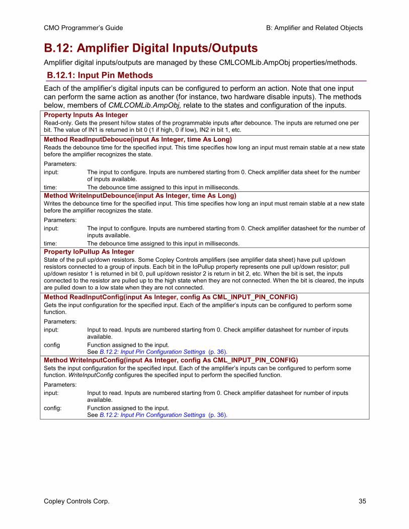
B.12: Amplifier Digital Inputs/Outputs Amplifier digital inputs/outputs are managed by these CMLCOMLib.AmpObj properties/methods.
B.12.1: Input Pin Methods Each of the amplifier’s digital inputs can be configured to perform an action. Note that one input can perform the same action as another (for instance, two hardware disable inputs). The methods below, members of CMLCOMLib.AmpObj, relate to the states and configuration of the inputs. Property Inputs As Integer Read-only. Gets the present hi/low states of the programmable inputs after debounce. The inputs are returned one per bit. The value of IN1 is returned in bit 0 (1 if high, 0 if low), IN2 in bit 1, etc. Method ReadInputDebouce(input As Integer, time As Long) Reads the debounce time for the specified input. This time specifies how long an input must remain stable at a new state before the amplifier recognizes the state. Parameters: input: The input to configure. Inputs are numbered starting from 0. Check amplifier data sheet for the number
of inputs available. time: The debounce time assigned to this input in milliseconds. Method WriteInputDebounce(input As Integer, time As Long) Writes the debounce time for the specified input. This time specifies how long an input must remain stable at a new state before the amplifier recognizes the state. Parameters: input: The input to configure. Inputs are numbered starting from 0. Check amplifier datasheet for the number of
inputs available. time: The debounce time assigned to this input in milliseconds. Property IoPullup As Integer State of the pull up/down resistors. Some Copley Controls amplifiers (see amplifier data sheet) have pull up/down resistors connected to a group of inputs. Each bit in the IoPullup property represents one pull up/down resistor; pull up/down resistor 1 is returned in bit 0, pull up/down resistor 2 is return in bit 2, etc. When the bit is set, the inputs connected to the resistor are pulled up to the high state when they are not connected. When the bit is cleared, the inputs are pulled down to a low state when they are not connected. Method ReadInputConfig(input As Integer, config As CML_INPUT_PIN_CONFIG) Gets the input configuration for the specified input. Each of the amplifier’s inputs can be configured to perform some function. Parameters: input: Input to read. Inputs are numbered starting from 0. Check amplifier datasheet for number of inputs
available. config Function assigned to the input.
See B.12.2: Input Pin Configuration Settings (p. 36). Method WriteInputConfig(input As Integer, config As CML_INPUT_PIN_CONFIG) Sets the input configuration for the specified input. Each of the amplifier’s inputs can be configured to perform some function. WriteInputConfig configures the specified input to perform the specified function. Parameters: input: Input to read. Inputs are numbered starting from 0. Check amplifier datasheet for number of inputs
available. config: Function assigned to the input.
See B.12.2: Input Pin Configuration Settings (p. 36).
B: Amplifier and Related Objects CMO Programmer’s Guide
36 Copley Controls Corp.
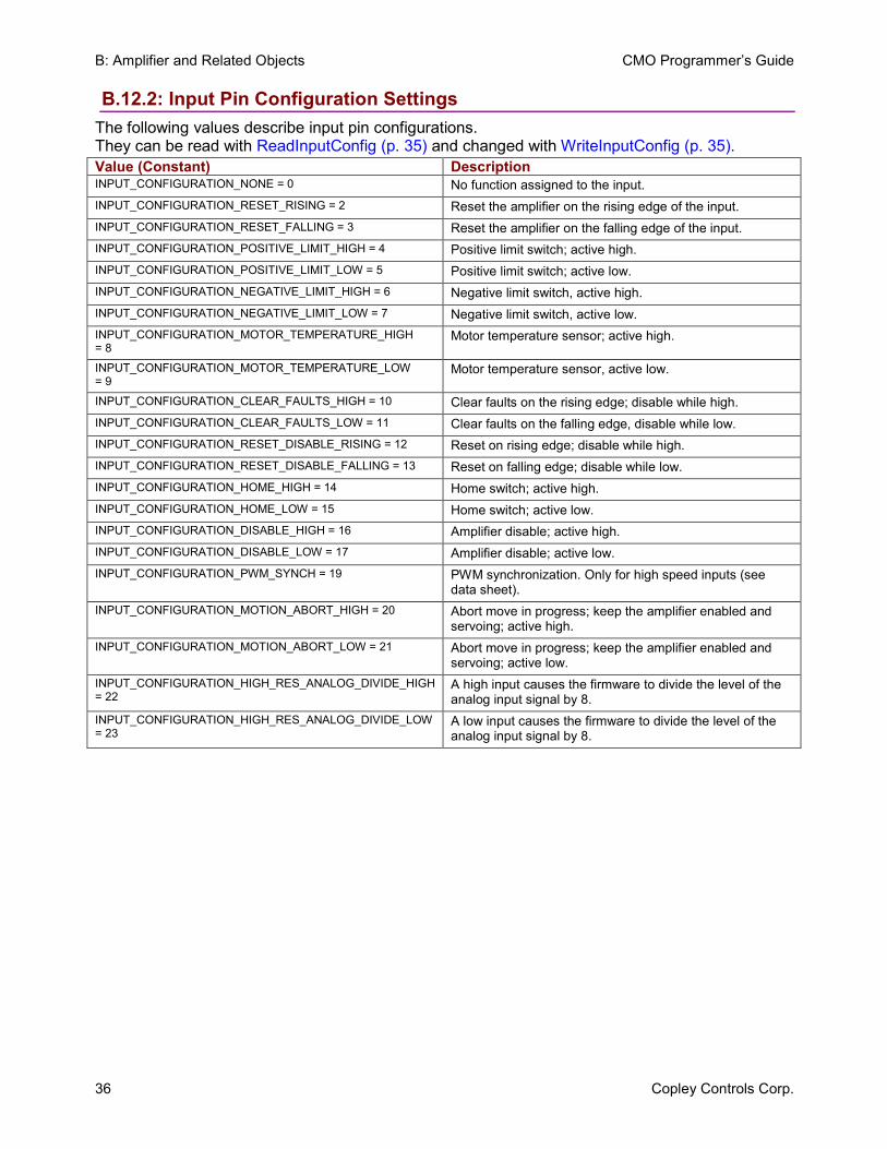
B.12.2: Input Pin Configuration Settings The following values describe input pin configurations. They can be read with ReadInputConfig (p. 35) and changed with WriteInputConfig (p. 35). Value (Constant) Description INPUT_CONFIGURATION_NONE = 0 No function assigned to the input. INPUT_CONFIGURATION_RESET_RISING = 2 Reset the amplifier on the rising edge of the input. INPUT_CONFIGURATION_RESET_FALLING = 3 Reset the amplifier on the falling edge of the input. INPUT_CONFIGURATION_POSITIVE_LIMIT_HIGH = 4 Positive limit switch; active high. INPUT_CONFIGURATION_POSITIVE_LIMIT_LOW = 5 Positive limit switch; active low. INPUT_CONFIGURATION_NEGATIVE_LIMIT_HIGH = 6 Negative limit switch, active high. INPUT_CONFIGURATION_NEGATIVE_LIMIT_LOW = 7 Negative limit switch, active low. INPUT_CONFIGURATION_MOTOR_TEMPERATURE_HIGH = 8
Motor temperature sensor; active high.
INPUT_CONFIGURATION_MOTOR_TEMPERATURE_LOW = 9
Motor temperature sensor, active low.
INPUT_CONFIGURATION_CLEAR_FAULTS_HIGH = 10 Clear faults on the rising edge; disable while high. INPUT_CONFIGURATION_CLEAR_FAULTS_LOW = 11 Clear faults on the falling edge, disable while low. INPUT_CONFIGURATION_RESET_DISABLE_RISING = 12 Reset on rising edge; disable while high. INPUT_CONFIGURATION_RESET_DISABLE_FALLING = 13 Reset on falling edge; disable while low. INPUT_CONFIGURATION_HOME_HIGH = 14 Home switch; active high. INPUT_CONFIGURATION_HOME_LOW = 15 Home switch; active low. INPUT_CONFIGURATION_DISABLE_HIGH = 16 Amplifier disable; active high. INPUT_CONFIGURATION_DISABLE_LOW = 17 Amplifier disable; active low. INPUT_CONFIGURATION_PWM_SYNCH = 19 PWM synchronization. Only for high speed inputs (see
data sheet). INPUT_CONFIGURATION_MOTION_ABORT_HIGH = 20 Abort move in progress; keep the amplifier enabled and
servoing; active high. INPUT_CONFIGURATION_MOTION_ABORT_LOW = 21 Abort move in progress; keep the amplifier enabled and
servoing; active low. INPUT_CONFIGURATION_HIGH_RES_ANALOG_DIVIDE_HIGH = 22
A high input causes the firmware to divide the level of the analog input signal by 8.
INPUT_CONFIGURATION_HIGH_RES_ANALOG_DIVIDE_LOW = 23
A low input causes the firmware to divide the level of the analog input signal by 8.
CMO Programmer’s Guide B: Amplifier and Related Objects
Copley Controls Corp. 37
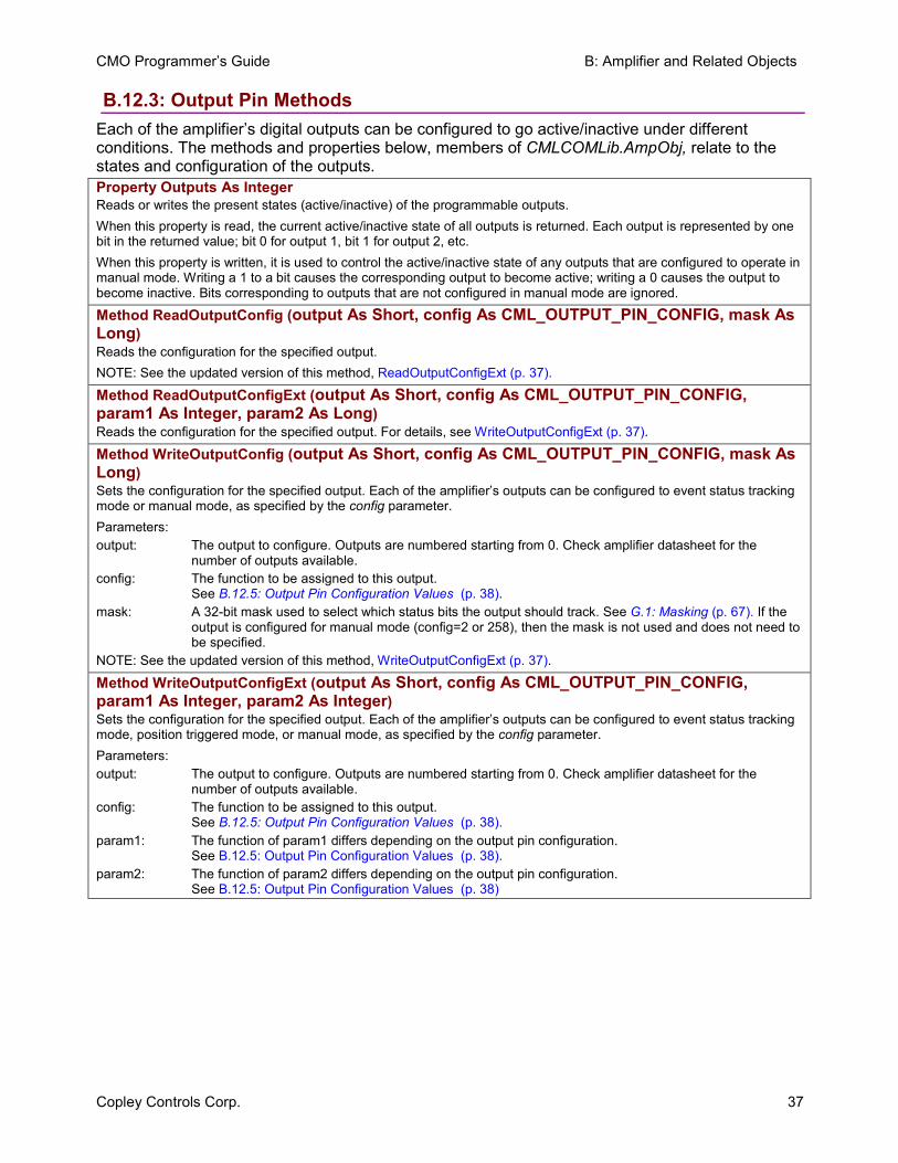
B.12.3: Output Pin Methods Each of the amplifier’s digital outputs can be configured to go active/inactive under different conditions. The methods and properties below, members of CMLCOMLib.AmpObj, relate to the states and configuration of the outputs. Property Outputs As Integer Reads or writes the present states (active/inactive) of the programmable outputs. When this property is read, the current active/inactive state of all outputs is returned. Each output is represented by one bit in the returned value; bit 0 for output 1, bit 1 for output 2, etc. When this property is written, it is used to control the active/inactive state of any outputs that are configured to operate in manual mode. Writing a 1 to a bit causes the corresponding output to become active; writing a 0 causes the output to become inactive. Bits corresponding to outputs that are not configured in manual mode are ignored.
Method ReadOutputConfig (output As Short, config As CML_OUTPUT_PIN_CONFIG, mask As Long)Reads the configuration for the specified output. NOTE: See the updated version of this method, ReadOutputConfigExt (p. 37).
Method ReadOutputConfigExt (output As Short, config As CML_OUTPUT_PIN_CONFIG, param1 As Integer, param2 As Long)Reads the configuration for the specified output. For details, see WriteOutputConfigExt (p. 37).
Method WriteOutputConfig (output As Short, config As CML_OUTPUT_PIN_CONFIG, mask As Long)Sets the configuration for the specified output. Each of the amplifier’s outputs can be configured to event status tracking mode or manual mode, as specified by the config parameter. Parameters: output: The output to configure. Outputs are numbered starting from 0. Check amplifier datasheet for the
number of outputs available. config: The function to be assigned to this output.
See B.12.5: Output Pin Configuration Values (p. 38).mask: A 32-bit mask used to select which status bits the output should track. See G.1: Masking (p. 67). If the
output is configured for manual mode (config=2 or 258), then the mask is not used and does not need to be specified.
NOTE: See the updated version of this method, WriteOutputConfigExt (p. 37).
Method WriteOutputConfigExt (output As Short, config As CML_OUTPUT_PIN_CONFIG, param1 As Integer, param2 As Integer)Sets the configuration for the specified output. Each of the amplifier’s outputs can be configured to event status tracking mode, position triggered mode, or manual mode, as specified by the config parameter. Parameters: output: The output to configure. Outputs are numbered starting from 0. Check amplifier datasheet for the
number of outputs available. config: The function to be assigned to this output.
See B.12.5: Output Pin Configuration Values (p. 38). param1: The function of param1 differs depending on the output pin configuration.
See B.12.5: Output Pin Configuration Values (p. 38).param2: The function of param2 differs depending on the output pin configuration.
See B.12.5: Output Pin Configuration Values (p. 38)
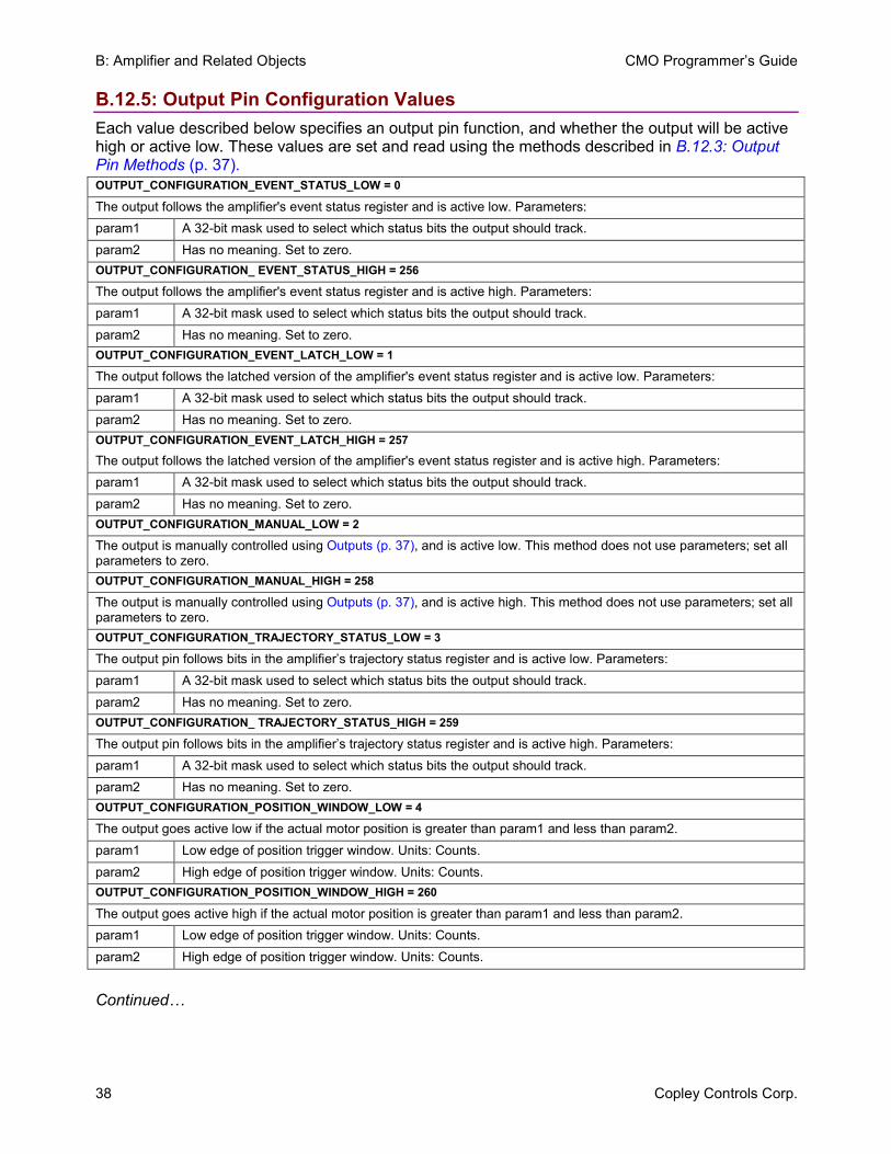
B: Amplifier and Related Objects CMO Programmer’s Guide
38 Copley Controls Corp.
B.12.5: Output Pin Configuration Values Each value described below specifies an output pin function, and whether the output will be active high or active low. These values are set and read using the methods described in B.12.3: Output Pin Methods (p. 37). OUTPUT_CONFIGURATION_EVENT_STATUS_LOW = 0 The output follows the amplifier's event status register and is active low. Parameters: param1 A 32-bit mask used to select which status bits the output should track. param2 Has no meaning. Set to zero. OUTPUT_CONFIGURATION_ EVENT_STATUS_HIGH = 256 The output follows the amplifier's event status register and is active high. Parameters: param1 A 32-bit mask used to select which status bits the output should track. param2 Has no meaning. Set to zero. OUTPUT_CONFIGURATION_EVENT_LATCH_LOW = 1 The output follows the latched version of the amplifier's event status register and is active low. Parameters: param1 A 32-bit mask used to select which status bits the output should track. param2 Has no meaning. Set to zero. OUTPUT_CONFIGURATION_EVENT_LATCH_HIGH = 257
The output follows the latched version of the amplifier's event status register and is active high. Parameters: param1 A 32-bit mask used to select which status bits the output should track. param2 Has no meaning. Set to zero. OUTPUT_CONFIGURATION_MANUAL_LOW = 2 The output is manually controlled using Outputs (p. 37), and is active low. This method does not use parameters; set all parameters to zero. OUTPUT_CONFIGURATION_MANUAL_HIGH = 258 The output is manually controlled using Outputs (p. 37), and is active high. This method does not use parameters; set all parameters to zero. OUTPUT_CONFIGURATION_TRAJECTORY_STATUS_LOW = 3 The output pin follows bits in the amplifier’s trajectory status register and is active low. Parameters: param1 A 32-bit mask used to select which status bits the output should track. param2 Has no meaning. Set to zero. OUTPUT_CONFIGURATION_ TRAJECTORY_STATUS_HIGH = 259 The output pin follows bits in the amplifier’s trajectory status register and is active high. Parameters: param1 A 32-bit mask used to select which status bits the output should track. param2 Has no meaning. Set to zero. OUTPUT_CONFIGURATION_POSITION_WINDOW_LOW = 4 The output goes active low if the actual motor position is greater than param1 and less than param2. param1 Low edge of position trigger window. Units: Counts. param2 High edge of position trigger window. Units: Counts. OUTPUT_CONFIGURATION_POSITION_WINDOW_HIGH = 260
The output goes active high if the actual motor position is greater than param1 and less than param2. param1 Low edge of position trigger window. Units: Counts. param2 High edge of position trigger window. Units: Counts.
Continued…
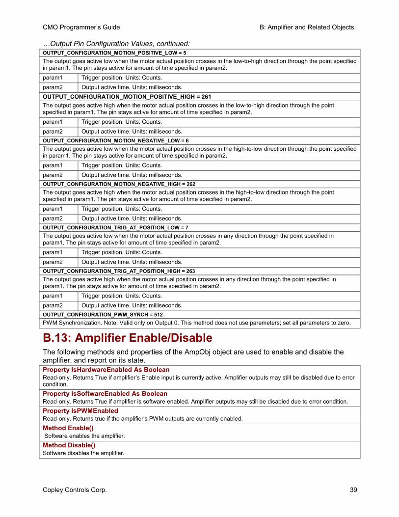
CMO Programmer’s Guide B: Amplifier and Related Objects
Copley Controls Corp. 39
…Output Pin Configuration Values, continued: OUTPUT_CONFIGURATION_MOTION_POSITIVE_LOW = 5 The output goes active low when the motor actual position crosses in the low-to-high direction through the point specified in param1. The pin stays active for amount of time specified in param2. param1 Trigger position. Units: Counts. param2 Output active time. Units: milliseconds. OUTPUT_CONFIGURATION_MOTION_POSITIVE_HIGH = 261 The output goes active high when the motor actual position crosses in the low-to-high direction through the point specified in param1. The pin stays active for amount of time specified in param2. param1 Trigger position. Units: Counts. param2 Output active time. Units: milliseconds. OUTPUT_CONFIGURATION_MOTION_NEGATIVE_LOW = 6 The output goes active low when the motor actual position crosses in the high-to-low direction through the point specified in param1. The pin stays active for amount of time specified in param2. param1 Trigger position. Units: Counts. param2 Output active time. Units: milliseconds. OUTPUT_CONFIGURATION_MOTION_NEGATIVE_HIGH = 262 The output goes active high when the motor actual position crosses in the high-to-low direction through the point specified in param1. The pin stays active for amount of time specified in param2. param1 Trigger position. Units: Counts. param2 Output active time. Units: milliseconds. OUTPUT_CONFIGURATION_TRIG_AT_POSITION_LOW = 7 The output goes active low when the motor actual position crosses in any direction through the point specified in param1. The pin stays active for amount of time specified in param2. param1 Trigger position. Units: Counts. param2 Output active time. Units: milliseconds. OUTPUT_CONFIGURATION_TRIG_AT_POSITION_HIGH = 263 The output goes active high when the motor actual position crosses in any direction through the point specified in param1. The pin stays active for amount of time specified in param2. param1 Trigger position. Units: Counts. param2 Output active time. Units: milliseconds. OUTPUT_CONFIGURATION_PWM_SYNCH = 512 PWM Synchronization. Note: Valid only on Output 0. This method does not use parameters; set all parameters to zero.
B.13: Amplifier Enable/Disable The following methods and properties of the AmpObj object are used to enable and disable the amplifier, and report on its state. Property IsHardwareEnabled As Boolean Read-only. Returns True if amplifier’s Enable input is currently active. Amplifier outputs may still be disabled due to error condition. Property IsSoftwareEnabled As Boolean Read-only. Returns True if amplifier is software enabled. Amplifier outputs may still be disabled due to error condition. Property IsPWMEnabled Read-only. Returns true if the amplifier's PWM outputs are currently enabled. Method Enable() Software enables the amplifier. Method Disable() Software disables the amplifier.
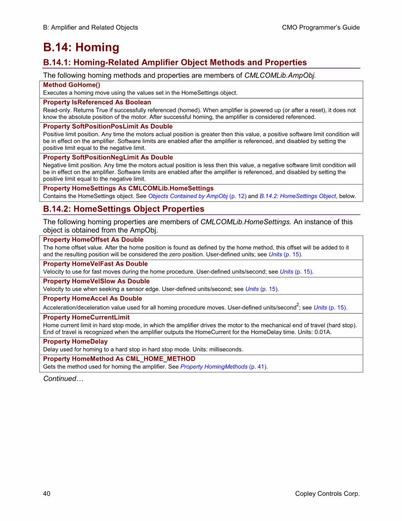
B: Amplifier and Related Objects CMO Programmer’s Guide
40 Copley Controls Corp.
B.14: Homing B.14.1: Homing-Related Amplifier Object Methods and Properties The following homing methods and properties are members of CMLCOMLib.AmpObj. Method GoHome() Executes a homing move using the values set in the HomeSettings object. Property IsReferenced As Boolean Read-only. Returns True if successfully referenced (homed). When amplifier is powered up (or after a reset), it does not know the absolute position of the motor. After successful homing, the amplifier is considered referenced. Property SoftPositionPosLimit As Double Positive limit position. Any time the motors actual position is greater then this value, a positive software limit condition will be in effect on the amplifier. Software limits are enabled after the amplifier is referenced, and disabled by setting the positive limit equal to the negative limit. Property SoftPositionNegLimit As Double Negative limit position. Any time the motors actual position is less then this value, a negative software limit condition will be in effect on the amplifier. Software limits are enabled after the amplifier is referenced, and disabled by setting the positive limit equal to the negative limit. Property HomeSettings As CMLCOMLib.HomeSettings Contains the HomeSettings object. See Objects Contained by AmpObj (p. 12) and B.14.2: HomeSettings Object, below.
B.14.2: HomeSettings Object Properties The following homing properties are members of CMLCOMLib.HomeSettings. An instance of this object is obtained from the AmpObj. Property HomeOffset As Double The home offset value. After the home position is found as defined by the home method, this offset will be added to it and the resulting position will be considered the zero position. User-defined units; see Units (p. 15). Property HomeVelFast As Double Velocity to use for fast moves during the home procedure. User-defined units/second; see Units (p. 15). Property HomeVelSlow As Double Velocity to use when seeking a sensor edge. User-defined units/second; see Units (p. 15). Property HomeAccel As Double Acceleration/deceleration value used for all homing procedure moves. User-defined units/second2; see Units (p. 15).
Property HomeCurrentLimit Home current limit in hard stop mode, in which the amplifier drives the motor to the mechanical end of travel (hard stop). End of travel is recognized when the amplifier outputs the HomeCurrent for the HomeDelay time. Units: 0.01A. Property HomeDelay Delay used for homing to a hard stop in hard stop mode. Units: milliseconds. Property HomeMethod As CML_HOME_METHOD Gets the method used for homing the amplifier. See Property HomingMethods (p. 41).
Continued…
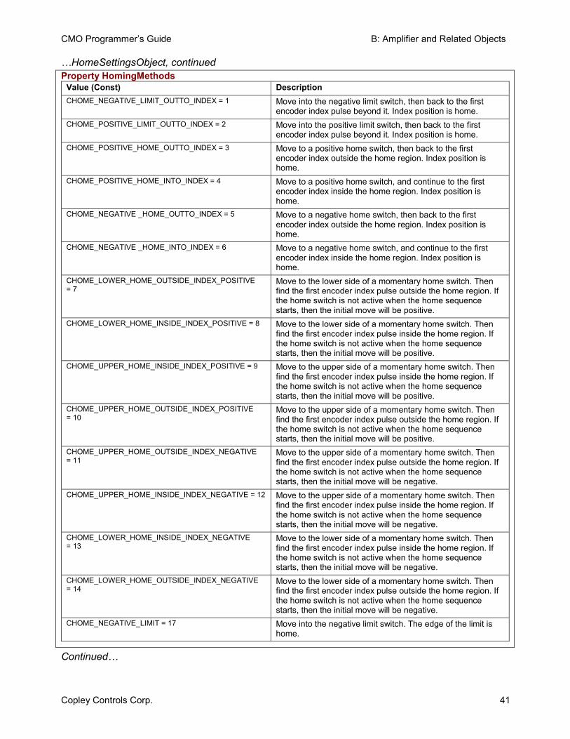
CMO Programmer’s Guide B: Amplifier and Related Objects
Copley Controls Corp. 41
…HomeSettingsObject, continued Property HomingMethods
Value (Const) Description CHOME_NEGATIVE_LIMIT_OUTTO_INDEX = 1 Move into the negative limit switch, then back to the first
encoder index pulse beyond it. Index position is home. CHOME_POSITIVE_LIMIT_OUTTO_INDEX = 2 Move into the positive limit switch, then back to the first
encoder index pulse beyond it. Index position is home. CHOME_POSITIVE_HOME_OUTTO_INDEX = 3 Move to a positive home switch, then back to the first
encoder index outside the home region. Index position is home.
CHOME_POSITIVE_HOME_INTO_INDEX = 4 Move to a positive home switch, and continue to the first encoder index inside the home region. Index position is home.
CHOME_NEGATIVE _HOME_OUTTO_INDEX = 5 Move to a negative home switch, then back to the first encoder index outside the home region. Index position is home.
CHOME_NEGATIVE _HOME_INTO_INDEX = 6 Move to a negative home switch, and continue to the first encoder index inside the home region. Index position is home.
CHOME_LOWER_HOME_OUTSIDE_INDEX_POSITIVE = 7
Move to the lower side of a momentary home switch. Then find the first encoder index pulse outside the home region. If the home switch is not active when the home sequence starts, then the initial move will be positive.
CHOME_LOWER_HOME_INSIDE_INDEX_POSITIVE = 8 Move to the lower side of a momentary home switch. Then find the first encoder index pulse inside the home region. If the home switch is not active when the home sequence starts, then the initial move will be positive.
CHOME_UPPER_HOME_INSIDE_INDEX_POSITIVE = 9 Move to the upper side of a momentary home switch. Then find the first encoder index pulse inside the home region. If the home switch is not active when the home sequence starts, then the initial move will be positive.
CHOME_UPPER_HOME_OUTSIDE_INDEX_POSITIVE = 10
Move to the upper side of a momentary home switch. Then find the first encoder index pulse outside the home region. If the home switch is not active when the home sequence starts, then the initial move will be positive.
CHOME_UPPER_HOME_OUTSIDE_INDEX_NEGATIVE = 11
Move to the upper side of a momentary home switch. Then find the first encoder index pulse outside the home region. If the home switch is not active when the home sequence starts, then the initial move will be negative.
CHOME_UPPER_HOME_INSIDE_INDEX_NEGATIVE = 12 Move to the upper side of a momentary home switch. Then find the first encoder index pulse inside the home region. If the home switch is not active when the home sequence starts, then the initial move will be negative.
CHOME_LOWER_HOME_INSIDE_INDEX_NEGATIVE = 13
Move to the lower side of a momentary home switch. Then find the first encoder index pulse inside the home region. If the home switch is not active when the home sequence starts, then the initial move will be negative.
CHOME_LOWER_HOME_OUTSIDE_INDEX_NEGATIVE = 14
Move to the lower side of a momentary home switch. Then find the first encoder index pulse outside the home region. If the home switch is not active when the home sequence starts, then the initial move will be negative.
CHOME_NEGATIVE_LIMIT = 17 Move into the negative limit switch. The edge of the limit is home.
Continued…
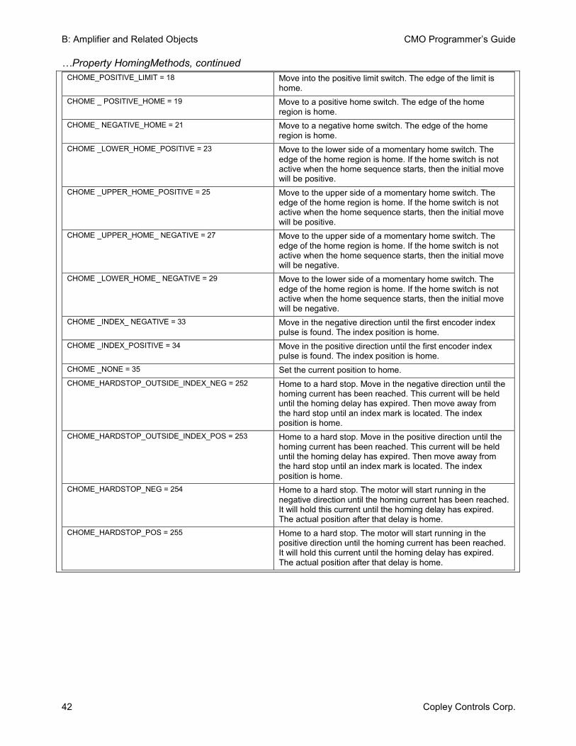
B: Amplifier and Related Objects CMO Programmer’s Guide
42 Copley Controls Corp.
…Property HomingMethods, continued CHOME_POSITIVE_LIMIT = 18 Move into the positive limit switch. The edge of the limit is
home. CHOME _ POSITIVE_HOME = 19 Move to a positive home switch. The edge of the home
region is home. CHOME_ NEGATIVE_HOME = 21 Move to a negative home switch. The edge of the home
region is home. CHOME _LOWER_HOME_POSITIVE = 23 Move to the lower side of a momentary home switch. The
edge of the home region is home. If the home switch is not active when the home sequence starts, then the initial move will be positive.
CHOME _UPPER_HOME_POSITIVE = 25 Move to the upper side of a momentary home switch. The edge of the home region is home. If the home switch is not active when the home sequence starts, then the initial move will be positive.
CHOME _UPPER_HOME_ NEGATIVE = 27 Move to the upper side of a momentary home switch. The edge of the home region is home. If the home switch is not active when the home sequence starts, then the initial move will be negative.
CHOME _LOWER_HOME_ NEGATIVE = 29 Move to the lower side of a momentary home switch. The edge of the home region is home. If the home switch is not active when the home sequence starts, then the initial move will be negative.
CHOME _INDEX_ NEGATIVE = 33 Move in the negative direction until the first encoder index pulse is found. The index position is home.
CHOME _INDEX_POSITIVE = 34 Move in the positive direction until the first encoder index pulse is found. The index position is home.
CHOME _NONE = 35 Set the current position to home. CHOME_HARDSTOP_OUTSIDE_INDEX_NEG = 252 Home to a hard stop. Move in the negative direction until the
homing current has been reached. This current will be held until the homing delay has expired. Then move away from the hard stop until an index mark is located. The index position is home.
CHOME_HARDSTOP_OUTSIDE_INDEX_POS = 253 Home to a hard stop. Move in the positive direction until the homing current has been reached. This current will be held until the homing delay has expired. Then move away from the hard stop until an index mark is located. The index position is home.
CHOME_HARDSTOP_NEG = 254 Home to a hard stop. The motor will start running in the negative direction until the homing current has been reached. It will hold this current until the homing delay has expired. The actual position after that delay is home.
CHOME_HARDSTOP_POS = 255 Home to a hard stop. The motor will start running in the positive direction until the homing current has been reached. It will hold this current until the homing delay has expired. The actual position after that delay is home.
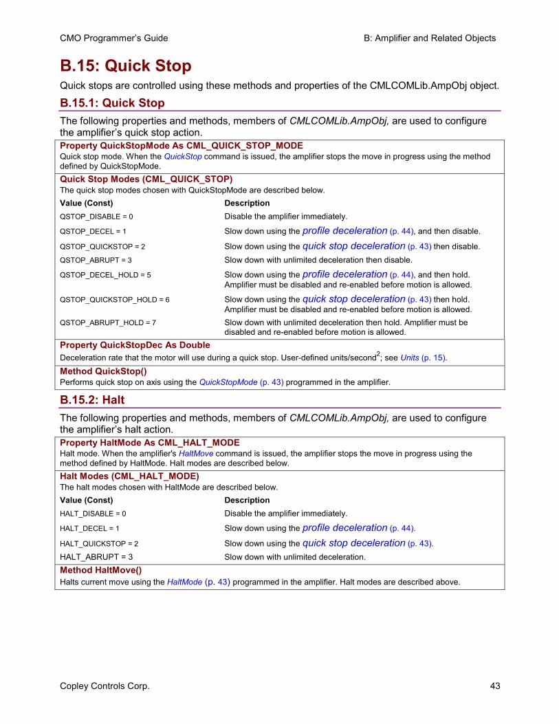
CMO Programmer’s Guide B: Amplifier and Related Objects
Copley Controls Corp. 43
B.15: Quick Stop Quick stops are controlled using these methods and properties of the CMLCOMLib.AmpObj object.
B.15.1: Quick Stop The following properties and methods, members of CMLCOMLib.AmpObj, are used to configure the amplifier’s quick stop action. Property QuickStopMode As CML_QUICK_STOP_MODE Quick stop mode. When the QuickStop command is issued, the amplifier stops the move in progress using the method defined by QuickStopMode. Quick Stop Modes (CML_QUICK_STOP) The quick stop modes chosen with QuickStopMode are described below. Value (Const) Description QSTOP_DISABLE = 0 Disable the amplifier immediately.
QSTOP_DECEL = 1 Slow down using the profile deceleration (p. 44), and then disable.
QSTOP_QUICKSTOP = 2 Slow down using the quick stop deceleration (p. 43) then disable. QSTOP_ABRUPT = 3 Slow down with unlimited deceleration then disable.
QSTOP_DECEL_HOLD = 5 Slow down using the profile deceleration (p. 44), and then hold. Amplifier must be disabled and re-enabled before motion is allowed.
QSTOP_QUICKSTOP_HOLD = 6 Slow down using the quick stop deceleration (p. 43) then hold. Amplifier must be disabled and re-enabled before motion is allowed.
QSTOP_ABRUPT_HOLD = 7 Slow down with unlimited deceleration then hold. Amplifier must be disabled and re-enabled before motion is allowed.
Property QuickStopDec As Double Deceleration rate that the motor will use during a quick stop. User-defined units/second2; see Units (p. 15).
Method QuickStop() Performs quick stop on axis using the QuickStopMode (p. 43) programmed in the amplifier.
B.15.2: Halt The following properties and methods, members of CMLCOMLib.AmpObj, are used to configure the amplifier’s halt action. Property HaltMode As CML_HALT_MODE Halt mode. When the amplifier's HaltMove command is issued, the amplifier stops the move in progress using the method defined by HaltMode. Halt modes are described below. Halt Modes (CML_HALT_MODE) The halt modes chosen with HaltMode are described below. Value (Const) Description HALT_DISABLE = 0 Disable the amplifier immediately.
HALT_DECEL = 1 Slow down using the profile deceleration (p. 44).
HALT_QUICKSTOP = 2 Slow down using the quick stop deceleration (p. 43). HALT_ABRUPT = 3 Slow down with unlimited deceleration. Method HaltMove() Halts current move using the HaltMode (p. 43) programmed in the amplifier. Halt modes are described above.
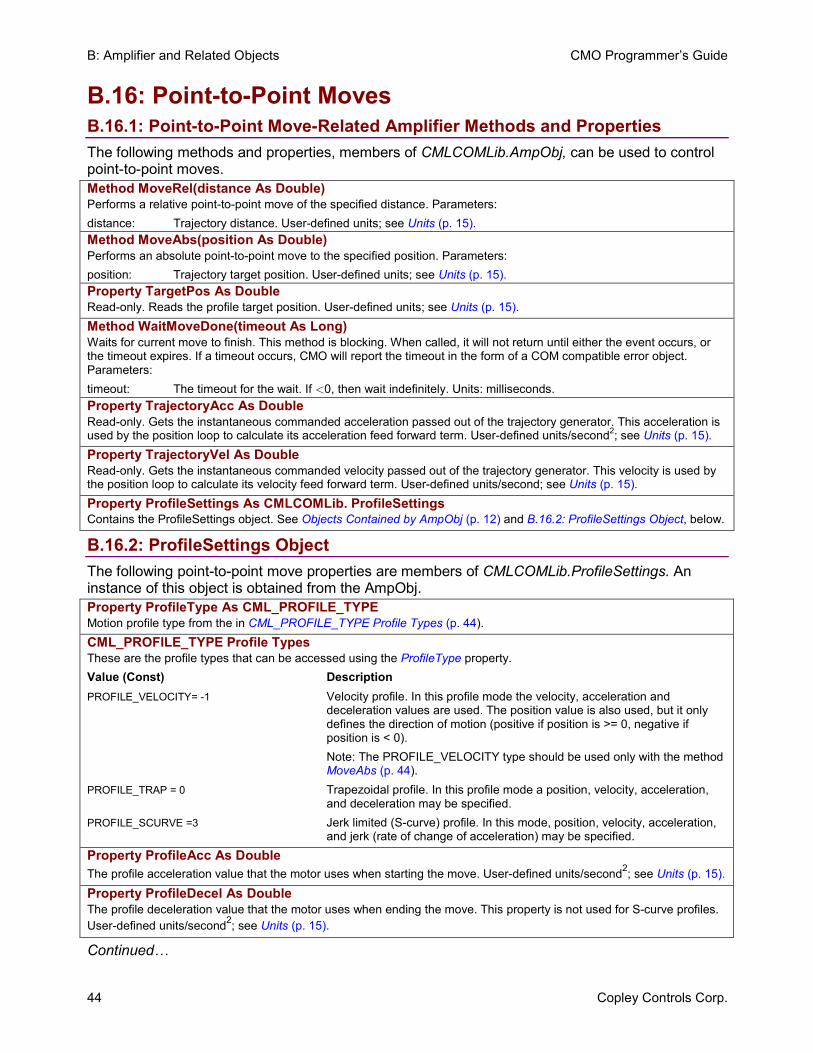
B: Amplifier and Related Objects CMO Programmer’s Guide
44 Copley Controls Corp.
B.16: Point-to-Point Moves B.16.1: Point-to-Point Move-Related Amplifier Methods and Properties The following methods and properties, members of CMLCOMLib.AmpObj, can be used to control point-to-point moves. Method MoveRel(distance As Double) Performs a relative point-to-point move of the specified distance. Parameters: distance: Trajectory distance. User-defined units; see Units (p. 15). Method MoveAbs(position As Double) Performs an absolute point-to-point move to the specified position. Parameters: position: Trajectory target position. User-defined units; see Units (p. 15). Property TargetPos As Double Read-only. Reads the profile target position. User-defined units; see Units (p. 15). Method WaitMoveDone(timeout As Long) Waits for current move to finish. This method is blocking. When called, it will not return until either the event occurs, or the timeout expires. If a timeout occurs, CMO will report the timeout in the form of a COM compatible error object. Parameters: timeout: The timeout for the wait. If <0, then wait indefinitely. Units: milliseconds. Property TrajectoryAcc As Double Read-only. Gets the instantaneous commanded acceleration passed out of the trajectory generator. This acceleration is used by the position loop to calculate its acceleration feed forward term. User-defined units/second2; see Units (p. 15). Property TrajectoryVel As Double Read-only. Gets the instantaneous commanded velocity passed out of the trajectory generator. This velocity is used by the position loop to calculate its velocity feed forward term. User-defined units/second; see Units (p. 15). Property ProfileSettings As CMLCOMLib. ProfileSettings Contains the ProfileSettings object. See Objects Contained by AmpObj (p. 12) and B.16.2: ProfileSettings Object, below.
B.16.2: ProfileSettings Object The following point-to-point move properties are members of CMLCOMLib.ProfileSettings. An instance of this object is obtained from the AmpObj. Property ProfileType As CML_PROFILE_TYPE Motion profile type from the in CML_PROFILE_TYPE Profile Types (p. 44). CML_PROFILE_TYPE Profile Types These are the profile types that can be accessed using the ProfileType property. Value (Const) Description PROFILE_VELOCITY= -1 Velocity profile. In this profile mode the velocity, acceleration and
deceleration values are used. The position value is also used, but it only defines the direction of motion (positive if position is >= 0, negative if position is < 0).
Note: The PROFILE_VELOCITY type should be used only with the method MoveAbs (p. 44).
PROFILE_TRAP = 0 Trapezoidal profile. In this profile mode a position, velocity, acceleration, and deceleration may be specified.
PROFILE_SCURVE =3 Jerk limited (S-curve) profile. In this mode, position, velocity, acceleration, and jerk (rate of change of acceleration) may be specified.
Property ProfileAcc As Double The profile acceleration value that the motor uses when starting the move. User-defined units/second2; see Units (p. 15).
Property ProfileDecel As Double The profile deceleration value that the motor uses when ending the move. This property is not used for S-curve profiles. User-defined units/second2; see Units (p. 15).
Continued…
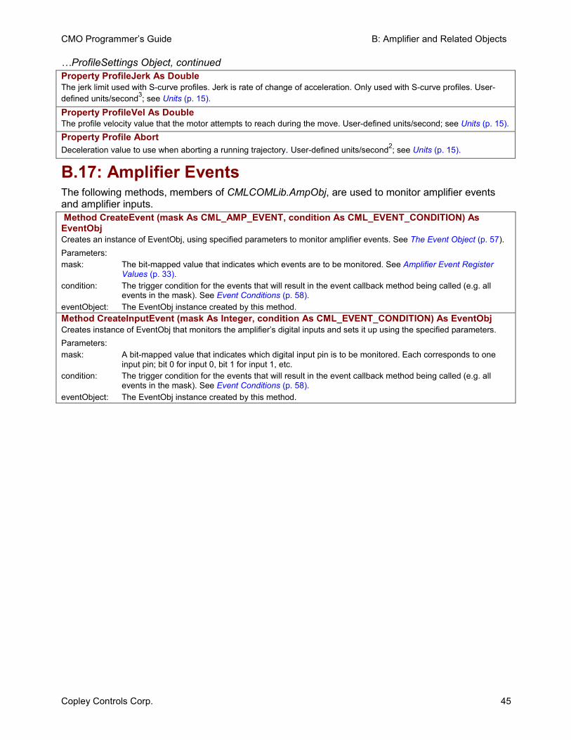
CMO Programmer’s Guide B: Amplifier and Related Objects
Copley Controls Corp. 45
…ProfileSettings Object, continued Property ProfileJerk As Double The jerk limit used with S-curve profiles. Jerk is rate of change of acceleration. Only used with S-curve profiles. User-defined units/second3; see Units (p. 15).
Property ProfileVel As Double The profile velocity value that the motor attempts to reach during the move. User-defined units/second; see Units (p. 15). Property Profile Abort Deceleration value to use when aborting a running trajectory. User-defined units/second2; see Units (p. 15).
B.17: Amplifier Events The following methods, members of CMLCOMLib.AmpObj, are used to monitor amplifier events and amplifier inputs. Method CreateEvent (mask As CML_AMP_EVENT, condition As CML_EVENT_CONDITION) As EventObj Creates an instance of EventObj, using specified parameters to monitor amplifier events. See The Event Object (p. 57). Parameters: mask: The bit-mapped value that indicates which events are to be monitored. See Amplifier Event Register
Values (p. 33). condition: The trigger condition for the events that will result in the event callback method being called (e.g. all
events in the mask). See Event Conditions (p. 58). eventObject: The EventObj instance created by this method. Method CreateInputEvent (mask As Integer, condition As CML_EVENT_CONDITION) As EventObj Creates instance of EventObj that monitors the amplifier’s digital inputs and sets it up using the specified parameters. Parameters: mask: A bit-mapped value that indicates which digital input pin is to be monitored. Each corresponds to one
input pin; bit 0 for input 0, bit 1 for input 1, etc. condition: The trigger condition for the events that will result in the event callback method being called (e.g. all
events in the mask). See Event Conditions (p. 58). eventObject: The EventObj instance created by this method.
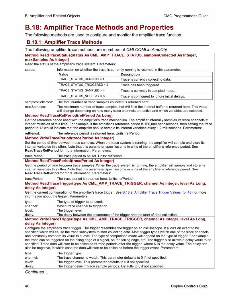
B: Amplifier and Related Objects CMO Programmer’s Guide
46 Copley Controls Corp.
B.18: Amplifier Trace Methods and Properties The following methods are used to configure and monitor the amplifier trace function.
B.18.1: Amplifier Trace Methods The following amplifier trace methods are members of CMLCOMLib.AmpObj. Method ReadTraceStatus(status As CML_AMP_TRACE_STATUS, samplesCollected As Integer, maxSamples As Integer) Read the status of the amplifier's trace system. Parameters: status: Information on whether the trace is currently running is returned in this parameter.
Value Description TRACE_STATUS_RUNNING = 1 Trace is currently collecting data. TRACE_STATUS_TRIGGERED = 2 Trace has been triggered. TRACE_STATUS_SAMPLED = 4 Trace is currently in sampled mode. TRACE_STATUS_NODELAY = 8 Trace is configured to ignore initial delays.
samplesCollected: The total number of trace samples collected is returned here. maxSamples: The maximum number of trace samples that will fit in the internal buffer is returned here. This value
will change depending on how many trace channels are active and which variables are selected. Method ReadTraceRefPeriod(refPeriod As Long) Get the reference period used with the amplifier’s trace mechanism. The amplifier internally samples its trace channels at integer multiples of this time. For example, if the amplifier's reference period is 100,000 nanoseconds, then setting the trace period to 12 would indicate that the amplifier should sample its internal variables every 1.2 milliseconds. Parameters: refPeriod: The reference period is returned here. Units: refPeriod. Method WriteTracePeriod(tracePeriod As Integer) Set the period of time between trace samples. When the trace system is running, the amplifier will sample and store its internal variables this often. Note that this parameter specifies time in units of the amplifier's reference period. See ReadTraceRefPeriod for more information. Parameters: tracePeriod: The trace period to be set. Units: refPeriod. Method ReadTracePeriod(tracePeriod As Integer) Get the period of time between trace samples. When the trace system is running, the amplifier will sample and store its internal variables this often. Note that this parameter specifies time in units of the amplifier's reference period. See ReadTraceRefPeriod for more information. Parameters: tracePeriod: The trace period is returned here. Units: refPeriod. Method ReadTraceTrigger(type As CML_AMP_TRACE_TRIGGER, channel As Integer, level As Long, delay As Integer) Get the current configuration of the amplifier's trace trigger. See B.18.2: Amplifier Trace Trigger Values (p. 48) for more information about the trigger. Parameters: type: The type of trigger to be used. channel: Which trace channel to trigger on. level: The trigger level. delay: The delay between the occurrence of the trigger and the start of data collection. Method WriteTraceTrigger(type As CML_AMP_TRACE_TRIGGER, channel As Integer, level As Long, delay As Integer) Configure the amplifier's trace trigger. The trigger resembles the trigger on an oscilloscope. It allows an event to be specified which will cause the trace subsystem to start collecting data. Most trigger types watch one of the trace channels and constantly compare its value to a level. The type of comparison made will depend on the type of trigger. For example, the trace can be triggered on the rising edge of a signal, on the falling edge, etc. The trigger also allows a delay value to be specified. Trace data will start to be collected N trace periods after the trigger, where N is the delay value. The delay can also be negative, in which case the data will start to be collected before the trigger event. Parameters: type: The trigger type. channel: The trace channel to watch. This parameter defaults to 0 if not specified. level: The trigger level. This parameter defaults to 0 if not specified. delay: The trigger delay in trace sample periods. Defaults to 0 if not specified.
Continued…
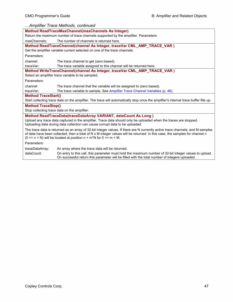
CMO Programmer’s Guide B: Amplifier and Related Objects
Copley Controls Corp. 47
…Amplifier Trace Methods, continued Method ReadTraceMaxChannel(maxChannels As Integer) Return the maximum number of trace channels supported by the amplifier. Parameters: maxChannels: The number of channels is returned here. Method ReadTraceChannel(channel As Integer, traceVar CML_AMP_TRACE_VAR ) Get the amplifier variable current selected on one of the trace channels. Parameters: channel: The trace channel to get (zero based). traceVar: The trace variable assigned to this channel will be returned here. Method WriteTraceChannel(channel As Integer, traceVar CML_AMP_TRACE_VAR ) Select an amplifier trace variable to be sampled. Parameters: channel: The trace channel that the variable will be assigned to (zero based). traceVar: The trace variable to sample. See Amplifier Trace Channel Variables (p. 48).Method TraceStart() Start collecting trace data on the amplifier. The trace will automatically stop once the amplifier's internal trace buffer fills up. Method TraceStop() Stop collecting trace data on the amplifier. Method ReadTraceData(traceDataArray VARIANT, dataCount As Long ) Upload any trace data captured in the amplifier. Trace data should only be uploaded when the traces are stopped. Uploading data during data collection can cause corrupt data to be uploaded. The trace data is returned as an array of 32-bit integer values. If there are N currently active trace channels, and M samples of data have been collected, then a total of N x M integer values will be returned. In this case, the samples for channel n (0 <= n < N) will be located at position n + m*N for 0 <= m < M. Parameters: traceDataArray: An array where the trace data will be returned. dataCount: On entry to this call, this parameter must hold the maximum number of 32-bit integer values to upload.
On successful return this parameter will be filled with the total number of integers uploaded.
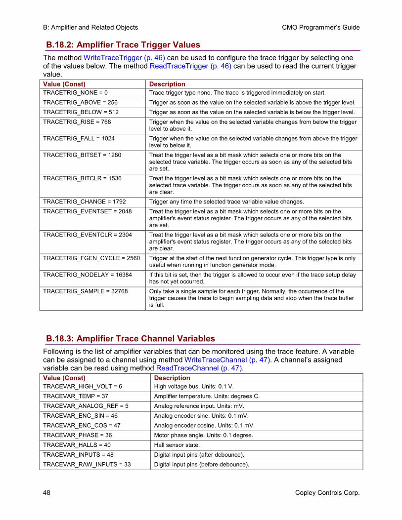
B: Amplifier and Related Objects CMO Programmer’s Guide
48 Copley Controls Corp.
B.18.2: Amplifier Trace Trigger Values The method WriteTraceTrigger (p. 46) can be used to configure the trace trigger by selecting one of the values below. The method ReadTraceTrigger (p. 46) can be used to read the current trigger value. Value (Const) Description TRACETRIG_NONE = 0 Trace trigger type none. The trace is triggered immediately on start. TRACETRIG_ABOVE = 256 Trigger as soon as the value on the selected variable is above the trigger level. TRACETRIG_BELOW = 512 Trigger as soon as the value on the selected variable is below the trigger level. TRACETRIG_RISE = 768 Trigger when the value on the selected variable changes from below the trigger
level to above it. TRACETRIG_FALL = 1024 Trigger when the value on the selected variable changes from above the trigger
level to below it. TRACETRIG_BITSET = 1280 Treat the trigger level as a bit mask which selects one or more bits on the
selected trace variable. The trigger occurs as soon as any of the selected bits are set.
TRACETRIG_BITCLR = 1536 Treat the trigger level as a bit mask which selects one or more bits on the selected trace variable. The trigger occurs as soon as any of the selected bits are clear.
TRACETRIG_CHANGE = 1792 Trigger any time the selected trace variable value changes. TRACETRIG_EVENTSET = 2048 Treat the trigger level as a bit mask which selects one or more bits on the
amplifier's event status register. The trigger occurs as any of the selected bits are set.
TRACETRIG_EVENTCLR = 2304 Treat the trigger level as a bit mask which selects one or more bits on the amplifier's event status register. The trigger occurs as any of the selected bits are clear.
TRACETRIG_FGEN_CYCLE = 2560 Trigger at the start of the next function generator cycle. This trigger type is only useful when running in function generator mode.
TRACETRIG_NODELAY = 16384 If this bit is set, then the trigger is allowed to occur even if the trace setup delay has not yet occurred.
TRACETRIG_SAMPLE = 32768 Only take a single sample for each trigger. Normally, the occurrence of the trigger causes the trace to begin sampling data and stop when the trace buffer is full.
B.18.3: Amplifier Trace Channel Variables Following is the list of amplifier variables that can be monitored using the trace feature. A variable can be assigned to a channel using method WriteTraceChannel (p. 47). A channel’s assigned variable can be read using method ReadTraceChannel (p. 47).Value (Const) Description TRACEVAR_HIGH_VOLT = 6 High voltage bus. Units: 0.1 V. TRACEVAR_TEMP = 37 Amplifier temperature. Units: degrees C. TRACEVAR_ANALOG_REF = 5 Analog reference input. Units: mV. TRACEVAR_ENC_SIN = 46 Analog encoder sine. Units: 0.1 mV. TRACEVAR_ENC_COS = 47 Analog encoder cosine. Units: 0.1 mV. TRACEVAR_PHASE = 36 Motor phase angle. Units: 0.1 degree. TRACEVAR_HALLS = 40 Hall sensor state. TRACEVAR_INPUTS = 48 Digital input pins (after debounce). TRACEVAR_RAW_INPUTS = 33 Digital input pins (before debounce).
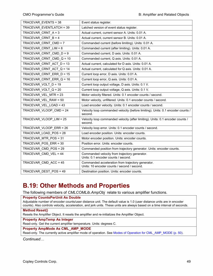
CMO Programmer’s Guide B: Amplifier and Related Objects
Copley Controls Corp. 49
TRACEVAR_EVENTS = 38 Event status register. TRACEVAR_EVENTLATCH = 39 Latched version of event status register. TRACEVAR_CRNT_A = 3 Actual current, current sensor A. Units: 0.01 A. TRACEVAR_CRNT_B = 4 Actual current, current sensor B. Units: 0.01 A. TRACEVAR_CRNT_CMD = 7 Commanded current (before limiting). Units: 0.01 A. TRACEVAR_CRNT_LIM = 8 Commanded current (after limiting). Units: 0.01 A. TRACEVAR_CRNT_CMD_D = 9 Commanded current, D axis. Units: 0.01 A. TRACEVAR_CRNT_CMD_Q = 10 Commanded current, Q axis. Units: 0.01 A. TRACEVAR_CRNT_ACT_D = 13 Actual current, calculated for D axis. Units: 0.01 A. TRACEVAR_CRNT_ACT_Q = 14 Actual current, calculated for Q axis. Units: 0.01 A. TRACEVAR_CRNT_ERR_D = 15 Current loop error, D axis. Units: 0.01 A. TRACEVAR_CRNT_ERR_Q = 16 Current loop error, Q axis. Units: 0.01 A. TRACEVAR_VOLT_D = 19 Current loop output voltage, D axis. Units: 0.1 V. TRACEVAR_VOLT_Q = 20 Current loop output voltage, Q axis. Units: 0.1 V. TRACEVAR_VEL_MTR = 23 Motor velocity filtered. Units: 0.1 encoder counts / second. TRACEVAR_VEL_RAW = 50 Motor velocity, unfiltered. Units: 0.1 encoder counts / second. TRACEVAR_VEL_LOAD = 43 Load encoder velocity. Units: 0.1 encoder counts / second. TRACEVAR_VLOOP_CMD = 24 Velocity loop commanded velocity (before limiting). Units: 0.1 encoder counts /
second. TRACEVAR_VLOOP_LIM = 25 Velocity loop commanded velocity (after limiting). Units: 0.1 encoder counts /
second. TRACEVAR_VLOOP_ERR = 26 Velocity loop error. Units: 0.1 encoder counts / second. TRACEVAR_LOAD_POS = 28 Load encoder position. Units: encoder counts. TRACEVAR_MTR_POS = 31 Motor encoder position. Units: encoder counts. TRACEVAR_POS_ERR = 30 Position error. Units: encoder counts. TRACEVAR_CMD_POS = 29 Commanded position from trajectory generator. Units: encoder counts. TRACEVAR_CMD_VEL = 44 Commanded velocity from trajectory generator.
Units: 0.1 encoder counts / second. TRACEVAR_CMD_ACC = 45 Commanded acceleration from trajectory generator.
Units: 10 encoder counts / second / second. TRACEVAR_DEST_POS = 49 Destination position. Units: encoder counts.
B.19: Other Methods and Properties The following members of CMLCOMLib.AmpObj relate to various amplifier functions. Property CountsPerUnit As Double Adjustable number of encoder counts/user distance unit. The default value is 1.0 (user distance units are in encoder counts). Also controls velocity, acceleration, and jerk units. These units are always based on a time interval of seconds. Method Reset() Resets the Amplifier Object. It resets the amplifier and re-initializes the Amplifier Object. Property AmpTemp As Integer Read-only. Get the current amplifier temperature. Units: degrees C. Property AmpMode As CML_AMP_MODE Read-only. The currently active amplifier mode of operation. See Modes of Operation for CML_AMP_MODE (p. 50).
Continued…
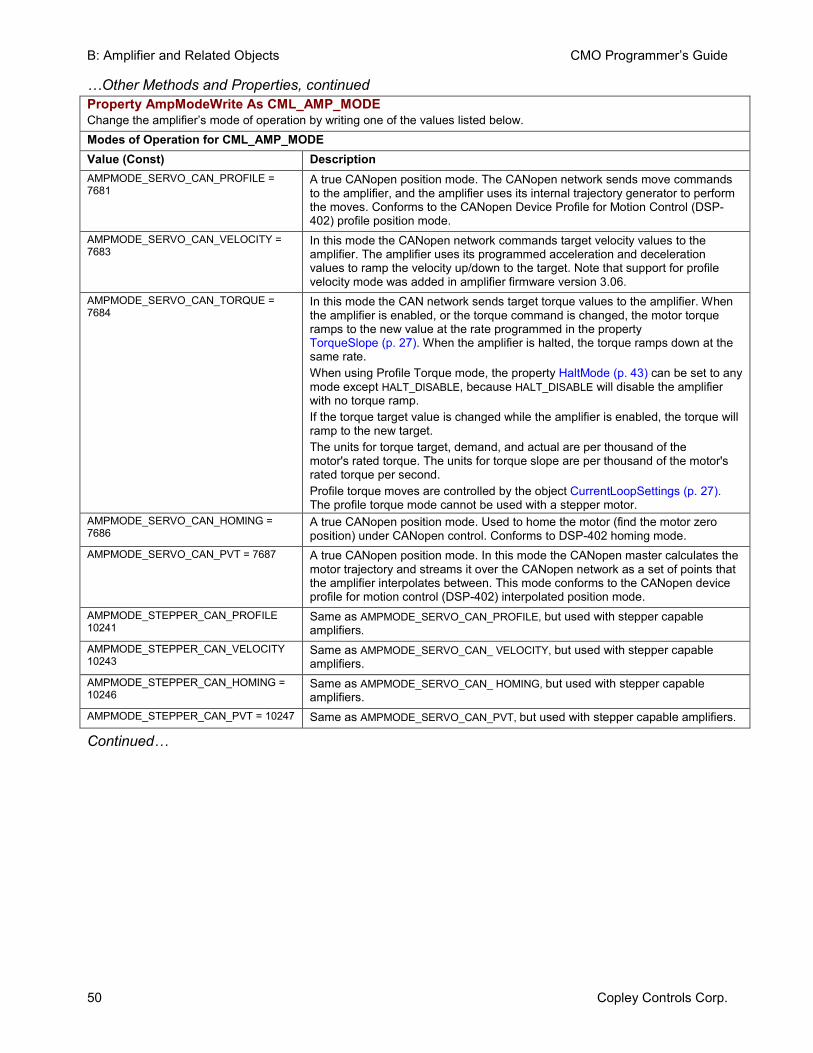
B: Amplifier and Related Objects CMO Programmer’s Guide
50 Copley Controls Corp.
…Other Methods and Properties, continued Property AmpModeWrite As CML_AMP_MODE Change the amplifier’s mode of operation by writing one of the values listed below. Modes of Operation for CML_AMP_MODE Value (Const) Description AMPMODE_SERVO_CAN_PROFILE = 7681
A true CANopen position mode. The CANopen network sends move commands to the amplifier, and the amplifier uses its internal trajectory generator to perform the moves. Conforms to the CANopen Device Profile for Motion Control (DSP-402) profile position mode.
AMPMODE_SERVO_CAN_VELOCITY = 7683
In this mode the CANopen network commands target velocity values to the amplifier. The amplifier uses its programmed acceleration and deceleration values to ramp the velocity up/down to the target. Note that support for profile velocity mode was added in amplifier firmware version 3.06.
AMPMODE_SERVO_CAN_TORQUE = 7684
In this mode the CAN network sends target torque values to the amplifier. When the amplifier is enabled, or the torque command is changed, the motor torque ramps to the new value at the rate programmed in the property TorqueSlope (p. 27). When the amplifier is halted, the torque ramps down at the same rate. When using Profile Torque mode, the property HaltMode (p. 43) can be set to any mode except HALT_DISABLE, because HALT_DISABLE will disable the amplifier with no torque ramp. If the torque target value is changed while the amplifier is enabled, the torque will ramp to the new target. The units for torque target, demand, and actual are per thousand of the motor's rated torque. The units for torque slope are per thousand of the motor's rated torque per second. Profile torque moves are controlled by the object CurrentLoopSettings (p. 27). The profile torque mode cannot be used with a stepper motor.
AMPMODE_SERVO_CAN_HOMING = 7686
A true CANopen position mode. Used to home the motor (find the motor zero position) under CANopen control. Conforms to DSP-402 homing mode.
AMPMODE_SERVO_CAN_PVT = 7687 A true CANopen position mode. In this mode the CANopen master calculates the motor trajectory and streams it over the CANopen network as a set of points that the amplifier interpolates between. This mode conforms to the CANopen device profile for motion control (DSP-402) interpolated position mode.
AMPMODE_STEPPER_CAN_PROFILE 10241
Same as AMPMODE_SERVO_CAN_PROFILE, but used with stepper capable amplifiers.
AMPMODE_STEPPER_CAN_VELOCITY 10243
Same as AMPMODE_SERVO_CAN_ VELOCITY, but used with stepper capable amplifiers.
AMPMODE_STEPPER_CAN_HOMING = 10246
Same as AMPMODE_SERVO_CAN_ HOMING, but used with stepper capable amplifiers.
AMPMODE_STEPPER_CAN_PVT = 10247 Same as AMPMODE_SERVO_CAN_PVT, but used with stepper capable amplifiers.
Continued…
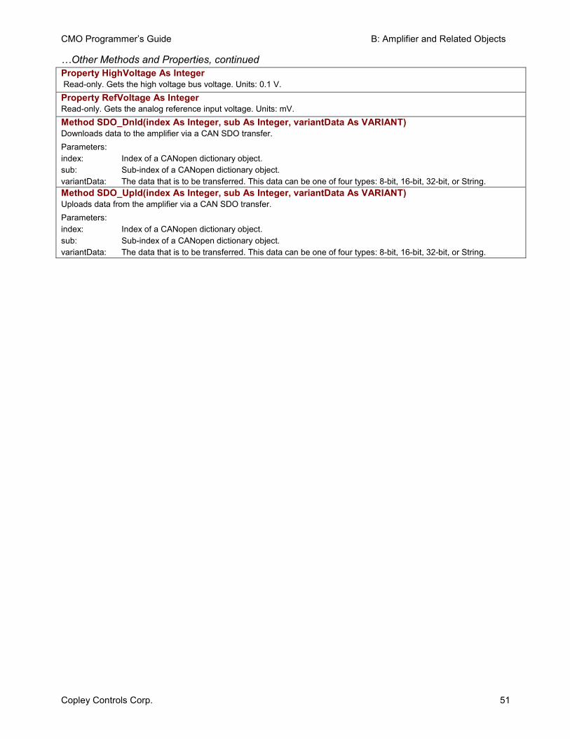
CMO Programmer’s Guide B: Amplifier and Related Objects
Copley Controls Corp. 51
…Other Methods and Properties, continued Property HighVoltage As Integer Read-only. Gets the high voltage bus voltage. Units: 0.1 V. Property RefVoltage As Integer Read-only. Gets the analog reference input voltage. Units: mV. Method SDO_Dnld(index As Integer, sub As Integer, variantData As VARIANT) Downloads data to the amplifier via a CAN SDO transfer. Parameters: index: Index of a CANopen dictionary object. sub: Sub-index of a CANopen dictionary object. variantData: The data that is to be transferred. This data can be one of four types: 8-bit, 16-bit, 32-bit, or String. Method SDO_Upld(index As Integer, sub As Integer, variantData As VARIANT) Uploads data from the amplifier via a CAN SDO transfer. Parameters: index: Index of a CANopen dictionary object. sub: Sub-index of a CANopen dictionary object. variantData: The data that is to be transferred. This data can be one of four types: 8-bit, 16-bit, 32-bit, or String.

B: Amplifier and Related Objects CMO Programmer’s Guide
52 Copley Controls Corp.
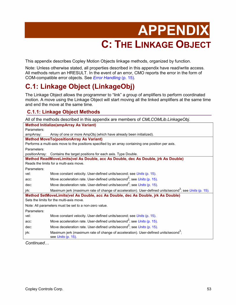
Copley Controls Corp. 53
APPENDIX C: THE LINKAGE OBJECT
This appendix describes Copley Motion Objects linkage methods, organized by function. Note: Unless otherwise stated, all properties described in this appendix have read/write access. All methods return an HRESULT. In the event of an error, CMO reports the error in the form of COM-compatible error objects. See Error Handling (p. 15).
C.1: Linkage Object (LinkageObj) The Linkage Object allows the programmer to “link” a group of amplifiers to perform coordinated motion. A move using the Linkage Object will start moving all the linked amplifiers at the same time and end the move at the same time.
C.1.1: Linkage Object Methods All of the methods described in this appendix are members of CMLCOMLib.LinkageObj.Method Initialize(ampArray As Variant) Parameters: ampArray: Array of one or more AmpObj (which have already been initialized). Method MoveTo(positionArray As Variant) Performs a multi-axis move to the positions specified by an array containing one position per axis. Parameters: positionArray: Contains the target positions for each axis. Type Double. Method ReadMoveLimits(vel As Double, acc As Double, dec As Double, jrk As Double) Reads the limits for a multi-axis move. Parameters: vel: Move constant velocity. User-defined units/second; see Units (p. 15). acc: Move acceleration rate. User-defined units/second2; see Units (p. 15). dec: Move deceleration rate. User-defined units/second2; see Units (p. 15). jrk: Maximum jerk (maximum rate of change of acceleration). User-defined units/second3; see Units (p. 15). Method SetMoveLimits(vel As Double, acc As Double, dec As Double, jrk As Double) Sets the limits for the multi-axis move. Note: All parameters must be set to a non-zero value. Parameters: vel: Move constant velocity. User-defined units/second; see Units (p. 15). acc: Move acceleration rate. User-defined units/second2; see Units (p. 15). dec: Move deceleration rate. User-defined units/second2; see Units (p. 15). jrk: Maximum jerk (maximum rate of change of acceleration). User-defined units/second3;
see Units (p. 15).
Continued…
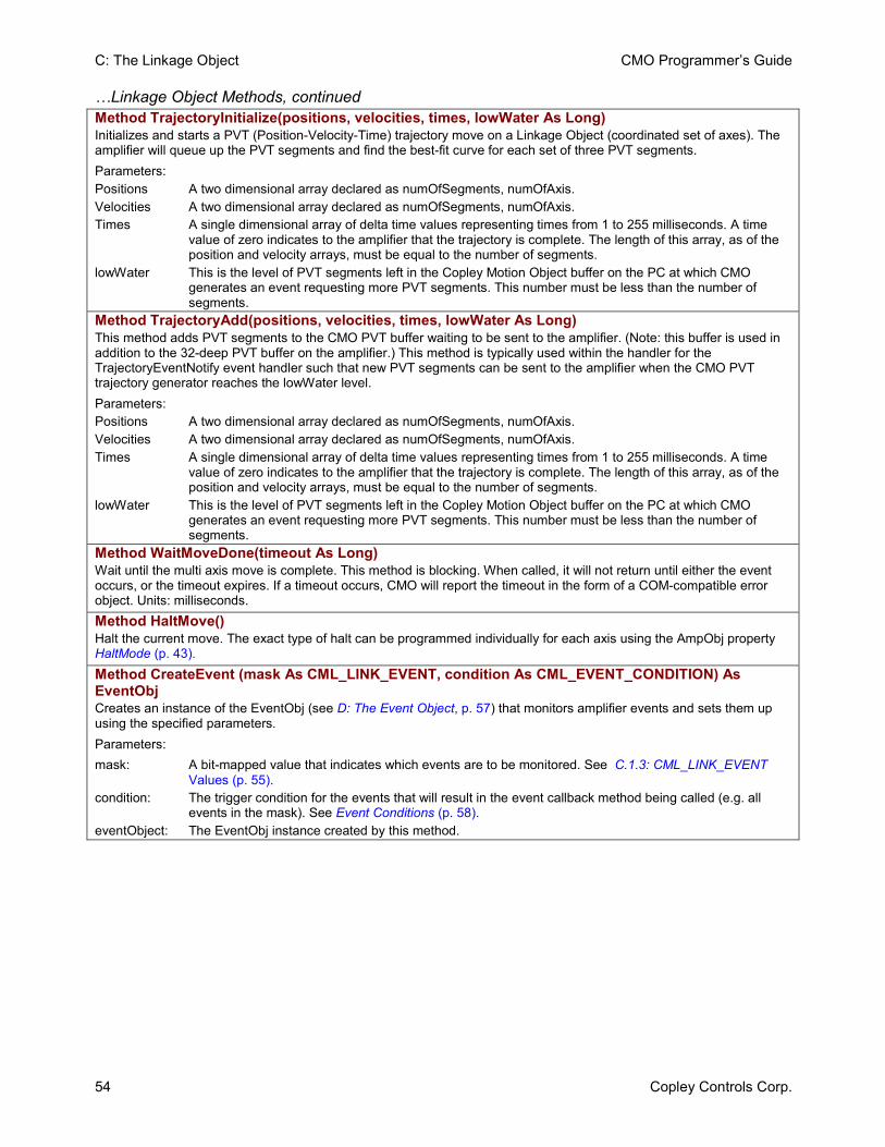
C: The Linkage Object CMO Programmer’s Guide
54 Copley Controls Corp.
…Linkage Object Methods, continued Method TrajectoryInitialize(positions, velocities, times, lowWater As Long) Initializes and starts a PVT (Position-Velocity-Time) trajectory move on a Linkage Object (coordinated set of axes). The amplifier will queue up the PVT segments and find the best-fit curve for each set of three PVT segments. Parameters: Positions A two dimensional array declared as numOfSegments, numOfAxis. Velocities A two dimensional array declared as numOfSegments, numOfAxis. Times A single dimensional array of delta time values representing times from 1 to 255 milliseconds. A time
value of zero indicates to the amplifier that the trajectory is complete. The length of this array, as of the position and velocity arrays, must be equal to the number of segments.
lowWater This is the level of PVT segments left in the Copley Motion Object buffer on the PC at which CMO generates an event requesting more PVT segments. This number must be less than the number of segments.
Method TrajectoryAdd(positions, velocities, times, lowWater As Long) This method adds PVT segments to the CMO PVT buffer waiting to be sent to the amplifier. (Note: this buffer is used in addition to the 32-deep PVT buffer on the amplifier.) This method is typically used within the handler for the TrajectoryEventNotify event handler such that new PVT segments can be sent to the amplifier when the CMO PVT trajectory generator reaches the lowWater level. Parameters: Positions A two dimensional array declared as numOfSegments, numOfAxis. Velocities A two dimensional array declared as numOfSegments, numOfAxis. Times A single dimensional array of delta time values representing times from 1 to 255 milliseconds. A time
value of zero indicates to the amplifier that the trajectory is complete. The length of this array, as of the position and velocity arrays, must be equal to the number of segments.
lowWater This is the level of PVT segments left in the Copley Motion Object buffer on the PC at which CMO generates an event requesting more PVT segments. This number must be less than the number of segments.
Method WaitMoveDone(timeout As Long) Wait until the multi axis move is complete. This method is blocking. When called, it will not return until either the event occurs, or the timeout expires. If a timeout occurs, CMO will report the timeout in the form of a COM-compatible error object. Units: milliseconds. Method HaltMove() Halt the current move. The exact type of halt can be programmed individually for each axis using the AmpObj property HaltMode (p. 43). Method CreateEvent (mask As CML_LINK_EVENT, condition As CML_EVENT_CONDITION) As EventObj Creates an instance of the EventObj (see D: The Event Object, p. 57) that monitors amplifier events and sets them up using the specified parameters. Parameters: mask: A bit-mapped value that indicates which events are to be monitored. See C.1.3: CML_LINK_EVENT
Values (p. 55). condition: The trigger condition for the events that will result in the event callback method being called (e.g. all
events in the mask). See Event Conditions (p. 58). eventObject: The EventObj instance created by this method.
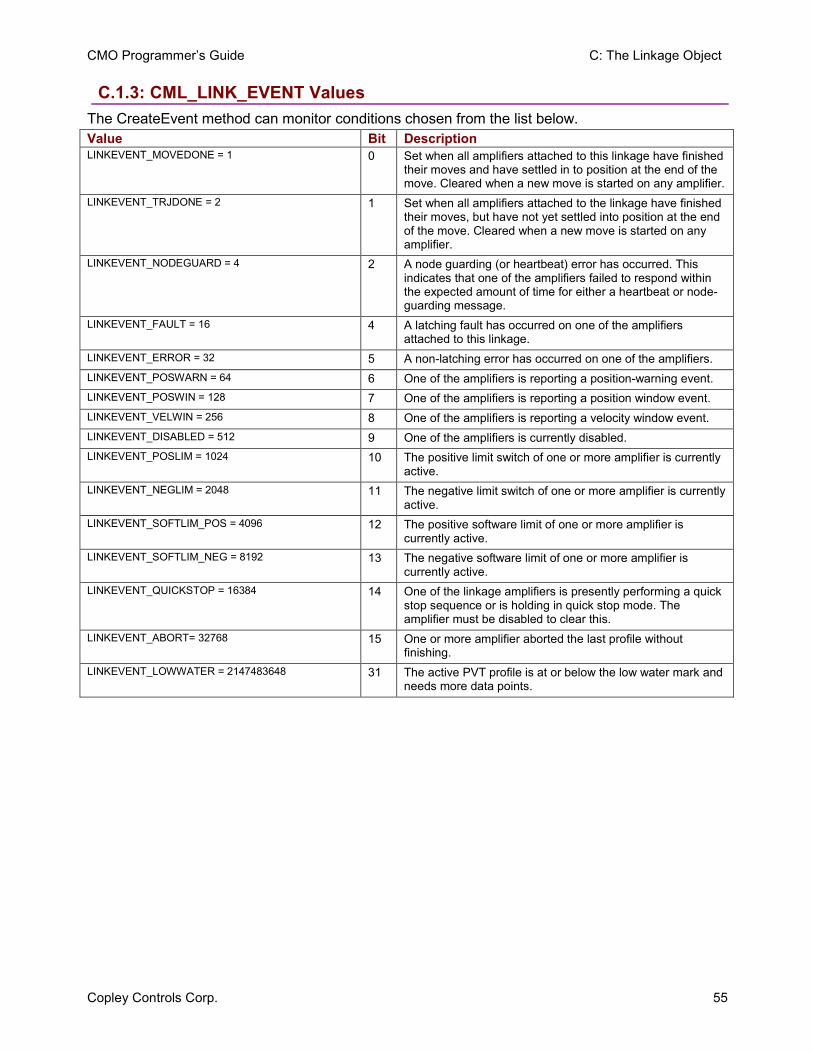
CMO Programmer’s Guide C: The Linkage Object
Copley Controls Corp. 55
C.1.3: CML_LINK_EVENT Values The CreateEvent method can monitor conditions chosen from the list below. Value Bit Description LINKEVENT_MOVEDONE = 1 0 Set when all amplifiers attached to this linkage have finished
their moves and have settled in to position at the end of the move. Cleared when a new move is started on any amplifier.
LINKEVENT_TRJDONE = 2 1 Set when all amplifiers attached to the linkage have finished their moves, but have not yet settled into position at the end of the move. Cleared when a new move is started on any amplifier.
LINKEVENT_NODEGUARD = 4 2 A node guarding (or heartbeat) error has occurred. This indicates that one of the amplifiers failed to respond within the expected amount of time for either a heartbeat or node-guarding message.
LINKEVENT_FAULT = 16 4 A latching fault has occurred on one of the amplifiers attached to this linkage.
LINKEVENT_ERROR = 32 5 A non-latching error has occurred on one of the amplifiers. LINKEVENT_POSWARN = 64 6 One of the amplifiers is reporting a position-warning event. LINKEVENT_POSWIN = 128 7 One of the amplifiers is reporting a position window event. LINKEVENT_VELWIN = 256 8 One of the amplifiers is reporting a velocity window event. LINKEVENT_DISABLED = 512 9 One of the amplifiers is currently disabled. LINKEVENT_POSLIM = 1024 10 The positive limit switch of one or more amplifier is currently
active. LINKEVENT_NEGLIM = 2048 11 The negative limit switch of one or more amplifier is currently
active. LINKEVENT_SOFTLIM_POS = 4096 12 The positive software limit of one or more amplifier is
currently active. LINKEVENT_SOFTLIM_NEG = 8192 13 The negative software limit of one or more amplifier is
currently active. LINKEVENT_QUICKSTOP = 16384 14 One of the linkage amplifiers is presently performing a quick
stop sequence or is holding in quick stop mode. The amplifier must be disabled to clear this.
LINKEVENT_ABORT= 32768 15 One or more amplifier aborted the last profile without finishing.
LINKEVENT_LOWWATER = 2147483648 31 The active PVT profile is at or below the low water mark and needs more data points.

C: The Linkage Object CMO Programmer’s Guide
56 Copley Controls Corp.
Copley Controls Corp. 57
APPENDIX D: THE EVENT OBJECT
This appendix describes the use of the Event Object. Note: All methods return an HRESULT. In the event of an error, CMO reports the error in the form of COM-compatible error objects. See Error Handling (p. 15).Contents include:
D.1: Event Object .................................................................................................................................... 58 D.1.1: Overview............................................................................................................................... 58 D.1.2: Event Object Methods .......................................................................................................... 58 D.1.3: Callback Method................................................................................................................... 58 D.1.4: Event Conditions .................................................................................................................. 58
E: The I/O Object CMO Programmer’s Guide
58 Copley Controls Corp.
D.1: Event Object D.1.1: Overview The EventObj allows an application program to be event-driven by having a procedure called when an event occurs in the amplifier. This allows the application program to continue execution while waiting for an event to occur. That is, the program is not blocked. For example, EventObj could call a procedure when a move is done, to perform some action such as performing the next move. The Event Object can be set up to perform a callback on a one-time basis or repeatedly. The EventObj is used in conjunction with the CMO objects that support events: AmpObj, LinkageObj, and IOObj. The CreateEvent method associated with each these three objects sets up the event monitor and returns an instance of the EventObj. See the following descriptions: CreateEvent Method for: See:
AmpObj CreateEvent (p. 45)
LinkageObj CreateEvent (p. 54)
IOObj CreateEvent (p. 60)
D.1.2: Event Object Methods All of the Methods described here are members of CMLCOMLib.EventObj.Method Start (repeats As Boolean, timeout As Long) Starts the event monitor. Parameters: repeats: Set to true to set up the event monitor to perform a callback each time the event occurs until the event
monitor is stopped. Set to false to set up the event monitor to perform a callback on a one-time basis. When set up for repeating events, the event condition must go away, then come back for the event callback to occur again.
timeout: The timeout for the wait. If <0, then wait indefinitely. Units: milliseconds. If the timeout expires before the event occurs, then the callback routine will be called with its second parameter (hasError) set to true.
Method Stop() Stops the event monitor. Method Wait(timeout As Long) Wait on the event. This method is blocking. When called, it will not return until either the event occurs, or the timeout expires. If a timeout occurs, CMO will report the timeout in the form of a COM compatible error object. Parameters: timeout: The timeout for the wait. If <0, then wait indefinitely. Units: milliseconds.
D.1.3: Callback Method EventNotify is a member of CMLCOMLib.EventObj.Event EventNotify(match As CML_AMP_EVENT, timeout As Boolean) Returns the contents of the register that was set up to trigger the event. The timeout variable will be true if the timeout period expired. Parameters: match: The contents of the register that was set up to trigger the event. timeout: True if a timeout or error occurred, False otherwise. Should be checked for an error condition before
processing the event handling code.
D.1.4: Event Conditions Each of the following is a member of CMLCOMLib.CML_EVENT_CONDITION. Used to select the event triggering condition. Const CML_EVENT_ANY = 1 Any event occurring. Const CML_EVENT_ALL = 2 All the events are required. Const CML_EVENT_NONE = 3 None of the events.
CMO Programmer’s Guide E: The I/O Object
Copley Controls Corp. 59
APPENDIX E: THE I/O OBJECT
This appendix describes IOObj2, used to access I/O devices that comply to the CiA profile DS-401: CANopen Device Profile for Generic I/O Modules. Note: Unless otherwise stated, all properties described in this appendix have read/write access. All methods return an HRESULT. In the event of an error, CMO reports the error in the form of COM-compatible error objects. See Error Handling (p. 15).Contents include:
E.1: I/O Modules...................................................................................................................................... 60 E.1.1: General IOObj Methods and Properties ............................................................................... 60 E.1.2: IOObj Methods and Properties for Analog Inputs................................................................. 61 E.1.3: IOObj Methods and Properties for Analog Outputs.............................................................. 62 E.1.4: IOObj Methods and Properties for Digital Inputs .................................................................. 63 E.1.5: IOObj Methods and Properties for Digital Outputs ............................................................... 64 E.1.6: IOSettingsObj ....................................................................................................................... 64
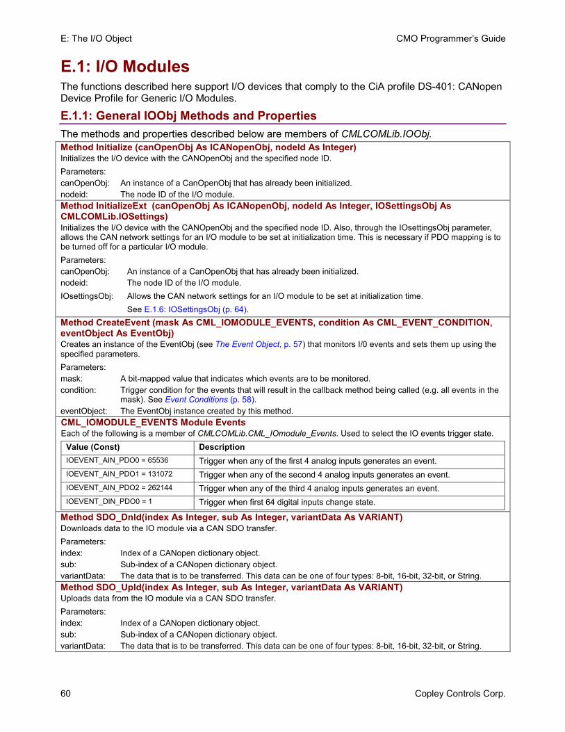
E: The I/O Object CMO Programmer’s Guide
60 Copley Controls Corp.
E.1: I/O Modules The functions described here support I/O devices that comply to the CiA profile DS-401: CANopen Device Profile for Generic I/O Modules.
E.1.1: General IOObj Methods and Properties The methods and properties described below are members of CMLCOMLib.IOObj. Method Initialize (canOpenObj As ICANopenObj, nodeId As Integer) Initializes the I/O device with the CANOpenObj and the specified node ID. Parameters: canOpenObj: An instance of a CanOpenObj that has already been initialized. nodeid: The node ID of the I/O module. Method InitializeExt (canOpenObj As ICANopenObj, nodeId As Integer, IOSettingsObj As CMLCOMLib.IOSettings) Initializes the I/O device with the CANOpenObj and the specified node ID. Also, through the IOsettingsObj parameter, allows the CAN network settings for an I/O module to be set at initialization time. This is necessary if PDO mapping is to be turned off for a particular I/O module. Parameters: canOpenObj: An instance of a CanOpenObj that has already been initialized. nodeid: The node ID of the I/O module. IOsettingsObj: Allows the CAN network settings for an I/O module to be set at initialization time. See E.1.6: IOSettingsObj (p. 64).Method CreateEvent (mask As CML_IOMODULE_EVENTS, condition As CML_EVENT_CONDITION, eventObject As EventObj) Creates an instance of the EventObj (see The Event Object, p. 57) that monitors I/0 events and sets them up using the specified parameters. Parameters: mask: A bit-mapped value that indicates which events are to be monitored. condition: Trigger condition for the events that will result in the callback method being called (e.g. all events in the
mask). See Event Conditions (p. 58).eventObject: The EventObj instance created by this method. CML_IOMODULE_EVENTS Module EventsEach of the following is a member of CMLCOMLib.CML_IOmodule_Events. Used to select the IO events trigger state.
Value (Const) Description IOEVENT_AIN_PDO0 = 65536 Trigger when any of the first 4 analog inputs generates an event. IOEVENT_AIN_PDO1 = 131072 Trigger when any of the second 4 analog inputs generates an event. IOEVENT_AIN_PDO2 = 262144 Trigger when any of the third 4 analog inputs generates an event. IOEVENT_DIN_PDO0 = 1 Trigger when first 64 digital inputs change state.
Method SDO_Dnld(index As Integer, sub As Integer, variantData As VARIANT) Downloads data to the IO module via a CAN SDO transfer. Parameters: index: Index of a CANopen dictionary object. sub: Sub-index of a CANopen dictionary object. variantData: The data that is to be transferred. This data can be one of four types: 8-bit, 16-bit, 32-bit, or String. Method SDO_Upld(index As Integer, sub As Integer, variantData As VARIANT) Uploads data from the IO module via a CAN SDO transfer. Parameters: index: Index of a CANopen dictionary object. sub: Sub-index of a CANopen dictionary object. variantData: The data that is to be transferred. This data can be one of four types: 8-bit, 16-bit, 32-bit, or String.
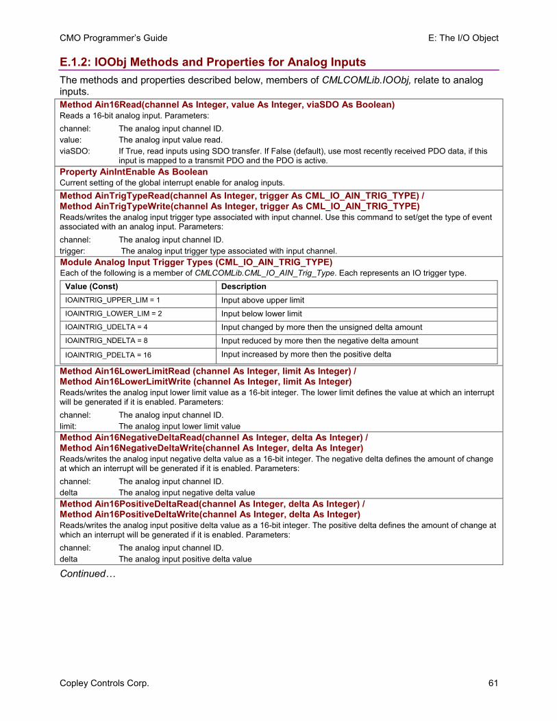
CMO Programmer’s Guide E: The I/O Object
Copley Controls Corp. 61
E.1.2: IOObj Methods and Properties for Analog Inputs The methods and properties described below, members of CMLCOMLib.IOObj, relate to analog inputs. Method Ain16Read(channel As Integer, value As Integer, viaSDO As Boolean) Reads a 16-bit analog input. Parameters: channel: The analog input channel ID. value: The analog input value read. viaSDO: If True, read inputs using SDO transfer. If False (default), use most recently received PDO data, if this
input is mapped to a transmit PDO and the PDO is active.Property AinIntEnable As Boolean Current setting of the global interrupt enable for analog inputs. Method AinTrigTypeRead(channel As Integer, trigger As CML_IO_AIN_TRIG_TYPE) / Method AinTrigTypeWrite(channel As Integer, trigger As CML_IO_AIN_TRIG_TYPE) Reads/writes the analog input trigger type associated with input channel. Use this command to set/get the type of event associated with an analog input. Parameters: channel: The analog input channel ID. trigger: The analog input trigger type associated with input channel. Module Analog Input Trigger Types (CML_IO_AIN_TRIG_TYPE) Each of the following is a member of CMLCOMLib.CML_IO_AIN_Trig_Type. Each represents an IO trigger type.
Value (Const) Description IOAINTRIG_UPPER_LIM = 1 Input above upper limit IOAINTRIG_LOWER_LIM = 2 Input below lower limit IOAINTRIG_UDELTA = 4 Input changed by more then the unsigned delta amount IOAINTRIG_NDELTA = 8 Input reduced by more then the negative delta amount
IOAINTRIG_PDELTA = 16 Input increased by more then the positive delta
Method Ain16LowerLimitRead (channel As Integer, limit As Integer) / Method Ain16LowerLimitWrite (channel As Integer, limit As Integer) Reads/writes the analog input lower limit value as a 16-bit integer. The lower limit defines the value at which an interrupt will be generated if it is enabled. Parameters: channel: The analog input channel ID. limit: The analog input lower limit value Method Ain16NegativeDeltaRead(channel As Integer, delta As Integer) / Method Ain16NegativeDeltaWrite(channel As Integer, delta As Integer) Reads/writes the analog input negative delta value as a 16-bit integer. The negative delta defines the amount of change at which an interrupt will be generated if it is enabled. Parameters: channel: The analog input channel ID. delta The analog input negative delta value Method Ain16PositiveDeltaRead(channel As Integer, delta As Integer) / Method Ain16PositiveDeltaWrite(channel As Integer, delta As Integer) Reads/writes the analog input positive delta value as a 16-bit integer. The positive delta defines the amount of change at which an interrupt will be generated if it is enabled. Parameters: channel: The analog input channel ID. delta The analog input positive delta value
Continued…
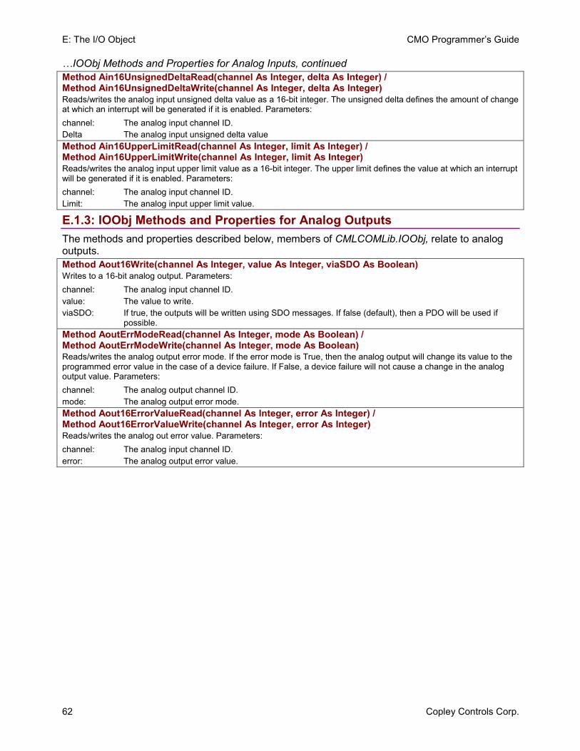
E: The I/O Object CMO Programmer’s Guide
62 Copley Controls Corp.
…IOObj Methods and Properties for Analog Inputs, continued Method Ain16UnsignedDeltaRead(channel As Integer, delta As Integer) / Method Ain16UnsignedDeltaWrite(channel As Integer, delta As Integer) Reads/writes the analog input unsigned delta value as a 16-bit integer. The unsigned delta defines the amount of change at which an interrupt will be generated if it is enabled. Parameters: channel: The analog input channel ID. Delta The analog input unsigned delta value Method Ain16UpperLimitRead(channel As Integer, limit As Integer) / Method Ain16UpperLimitWrite(channel As Integer, limit As Integer) Reads/writes the analog input upper limit value as a 16-bit integer. The upper limit defines the value at which an interrupt will be generated if it is enabled. Parameters: channel: The analog input channel ID. Limit: The analog input upper limit value.
E.1.3: IOObj Methods and Properties for Analog Outputs The methods and properties described below, members of CMLCOMLib.IOObj, relate to analog outputs. Method Aout16Write(channel As Integer, value As Integer, viaSDO As Boolean) Writes to a 16-bit analog output. Parameters: channel: The analog input channel ID. value: The value to write. viaSDO: If true, the outputs will be written using SDO messages. If false (default), then a PDO will be used if
possible. Method AoutErrModeRead(channel As Integer, mode As Boolean) / Method AoutErrModeWrite(channel As Integer, mode As Boolean) Reads/writes the analog output error mode. If the error mode is True, then the analog output will change its value to the programmed error value in the case of a device failure. If False, a device failure will not cause a change in the analog output value. Parameters: channel: The analog output channel ID. mode: The analog output error mode. Method Aout16ErrorValueRead(channel As Integer, error As Integer) / Method Aout16ErrorValueWrite(channel As Integer, error As Integer) Reads/writes the analog out error value. Parameters: channel: The analog input channel ID. error: The analog output error value.
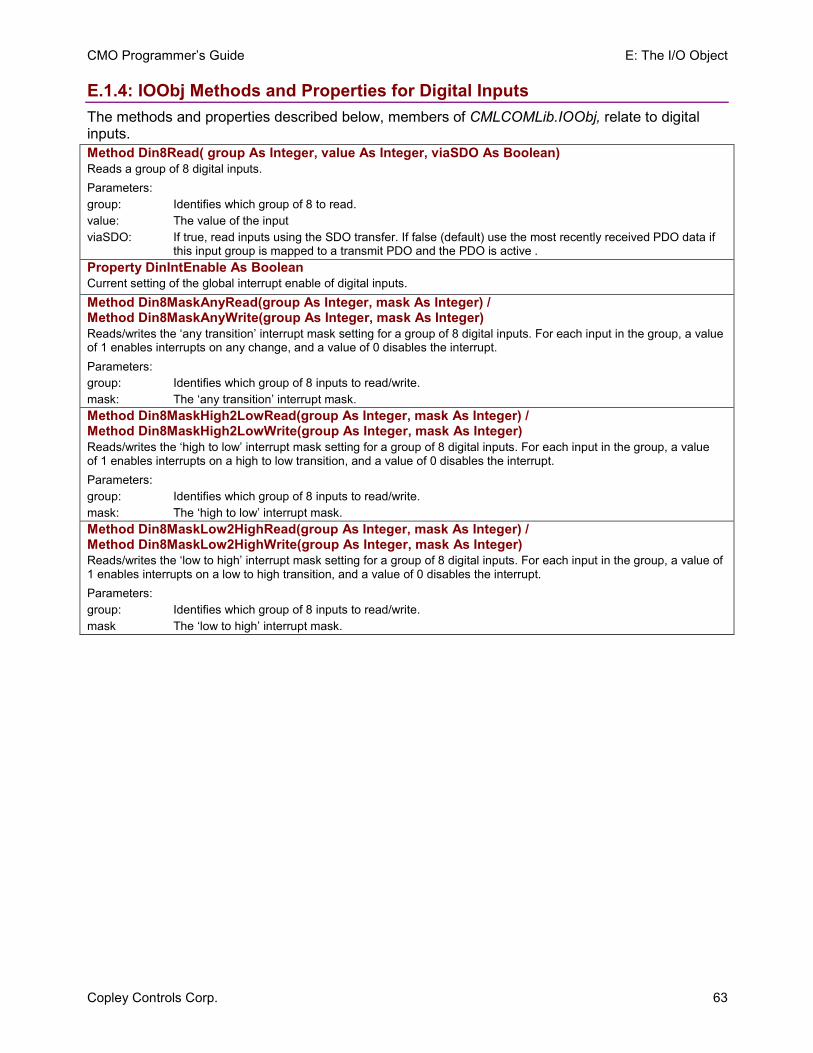
CMO Programmer’s Guide E: The I/O Object
Copley Controls Corp. 63
E.1.4: IOObj Methods and Properties for Digital Inputs The methods and properties described below, members of CMLCOMLib.IOObj, relate to digital inputs. Method Din8Read( group As Integer, value As Integer, viaSDO As Boolean) Reads a group of 8 digital inputs. Parameters: group: Identifies which group of 8 to read. value: The value of the input viaSDO: If true, read inputs using the SDO transfer. If false (default) use the most recently received PDO data if
this input group is mapped to a transmit PDO and the PDO is active .Property DinIntEnable As Boolean Current setting of the global interrupt enable of digital inputs. Method Din8MaskAnyRead(group As Integer, mask As Integer) / Method Din8MaskAnyWrite(group As Integer, mask As Integer) Reads/writes the ‘any transition’ interrupt mask setting for a group of 8 digital inputs. For each input in the group, a value of 1 enables interrupts on any change, and a value of 0 disables the interrupt. Parameters: group: Identifies which group of 8 inputs to read/write. mask: The ‘any transition’ interrupt mask. Method Din8MaskHigh2LowRead(group As Integer, mask As Integer) / Method Din8MaskHigh2LowWrite(group As Integer, mask As Integer) Reads/writes the ‘high to low’ interrupt mask setting for a group of 8 digital inputs. For each input in the group, a value of 1 enables interrupts on a high to low transition, and a value of 0 disables the interrupt. Parameters: group: Identifies which group of 8 inputs to read/write. mask: The ‘high to low’ interrupt mask. Method Din8MaskLow2HighRead(group As Integer, mask As Integer) / Method Din8MaskLow2HighWrite(group As Integer, mask As Integer) Reads/writes the ‘low to high’ interrupt mask setting for a group of 8 digital inputs. For each input in the group, a value of 1 enables interrupts on a low to high transition, and a value of 0 disables the interrupt. Parameters: group: Identifies which group of 8 inputs to read/write. mask The ‘low to high’ interrupt mask.
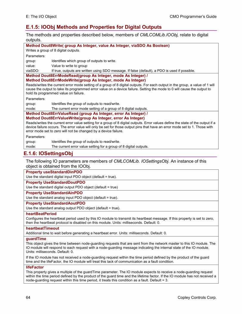
E: The I/O Object CMO Programmer’s Guide
64 Copley Controls Corp.
E.1.5: IOObj Methods and Properties for Digital Outputs The methods and properties described below, members of CMLCOMLib.IOObj, relate to digital outputs. Method Dout8Write( group As Integer, value As Integer, viaSDO As Boolean) Writes a group of 8 digital outputs. Parameters: group: Identifies which group of outputs to write. value: Value to write to group viaSDO: If true, outputs are written using SDO message. If false (default), a PDO is used if possible. Method Dout8ErrModeRead(group As Integer, mode As Integer) / Method Dout8ErrModeWrite(group As Integer, mode As Integer) Reads/writes the current error mode setting of a group of 8 digital outputs. For each output in the group, a value of 1 will cause the output to take its programmed error value on a device failure. Setting the mode to 0 will cause the output to hold its programmed value on failure. Parameters: group: Identifies the group of outputs to read/write. mode: The current error mode setting of a group of 8 digital outputs. Method Dout8ErrValueRead (group As Integer, error As Integer) / Method Dout8ErrValueWrite(group As Integer, error As Integer) Reads/writes the current error value setting for a group of 8 digital outputs. Error values define the state of the output if a device failure occurs. The error value will only be set for those output pins that have an error mode set to 1. Those with error mode set to zero will not be changed by a device failure. Parameters: group: Identifies the group of outputs to read/write. mode: The current error value setting for a group of 8 digital outputs.
E.1.6: IOSettingsObj The following IO parameters are members of CMLCOMLib. IOSettingsObj. An instance of this object is obtained from the IOObj. Property useStandardDinPDO Use the standard digital input PDO object (default = true). Property UseStandardDoutPDO Use the standard digital output PDO object (default = true) Property UseStandardAinPDO Use the standard analog input PDO object (default = true). Property UseStandardAoutPDO Use the standard analog output PDO object (default = true). heartBeatPeriod Configures the heartbeat period used by this IO module to transmit its heartbeat message. If this property is set to zero, then the heartbeat protocol is disabled on this module. Units: milliseconds. Default: 0. heartbeatTimeout Additional time to wait before generating a heartbeat error. Units: milliseconds. Default: 0. guardTime This object gives the time between node-guarding requests that are sent from the network master to this IO module. The IO module will respond to each request with a node-guarding message indicating the internal state of the IO module. Units: milliseconds. Default: 0. If the IO module has not received a node-guarding request within the time period defined by the product of the guard time and the lifeFactor, the IO module will treat this lack of communication as a fault condition. lifeFactor This property gives a multiple of the guardTime parameter. The IO module expects to receive a node-guarding request within the time period defined by the product of the guard time and the lifetime factor. If the IO module has not received a node-guarding request within this time period, it treats this condition as a fault. Default = 3.
Copley Controls Corp. 65
APPENDIX F: COPLEYMOTIONLIBRARY OBJECT
This appendix describes CopleyMotionLibraryObj, which includes the ability to log communication traffic for debugging purposes. Contents include:
F.1: CopleyMotionLibraryObj .................................................................................................................. 66 F.1.1: CopleyMotionLibraryObj ....................................................................................................... 66
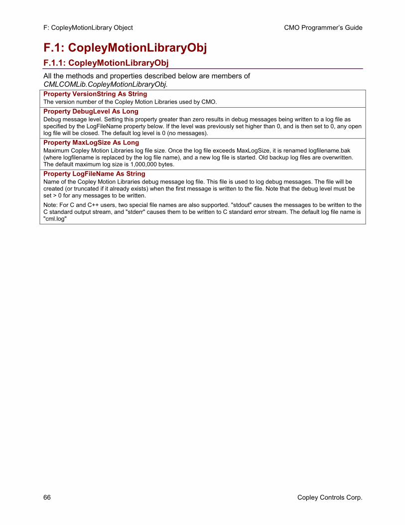
F: CopleyMotionLibrary Object CMO Programmer’s Guide
66 Copley Controls Corp.
F.1: CopleyMotionLibraryObj F.1.1: CopleyMotionLibraryObj All the methods and properties described below are members of CMLCOMLib.CopleyMotionLibraryObj. Property VersionString As String The version number of the Copley Motion Libraries used by CMO. Property DebugLevel As Long Debug message level. Setting this property greater than zero results in debug messages being written to a log file as specified by the LogFileName property below. If the level was previously set higher than 0, and is then set to 0, any open log file will be closed. The default log level is 0 (no messages). Property MaxLogSize As Long Maximum Copley Motion Libraries log file size. Once the log file exceeds MaxLogSize, it is renamed logfilename.bak (where logfilename is replaced by the log file name), and a new log file is started. Old backup log files are overwritten. The default maximum log size is 1,000,000 bytes. Property LogFileName As String Name of the Copley Motion Libraries debug message log file. This file is used to log debug messages. The file will be created (or truncated if it already exists) when the first message is written to the file. Note that the debug level must be set > 0 for any messages to be written. Note: For C and C++ users, two special file names are also supported. "stdout" causes the messages to be written to the C standard output stream, and "stderr" causes them to be written to C standard error stream. The default log file name is "cml.log"
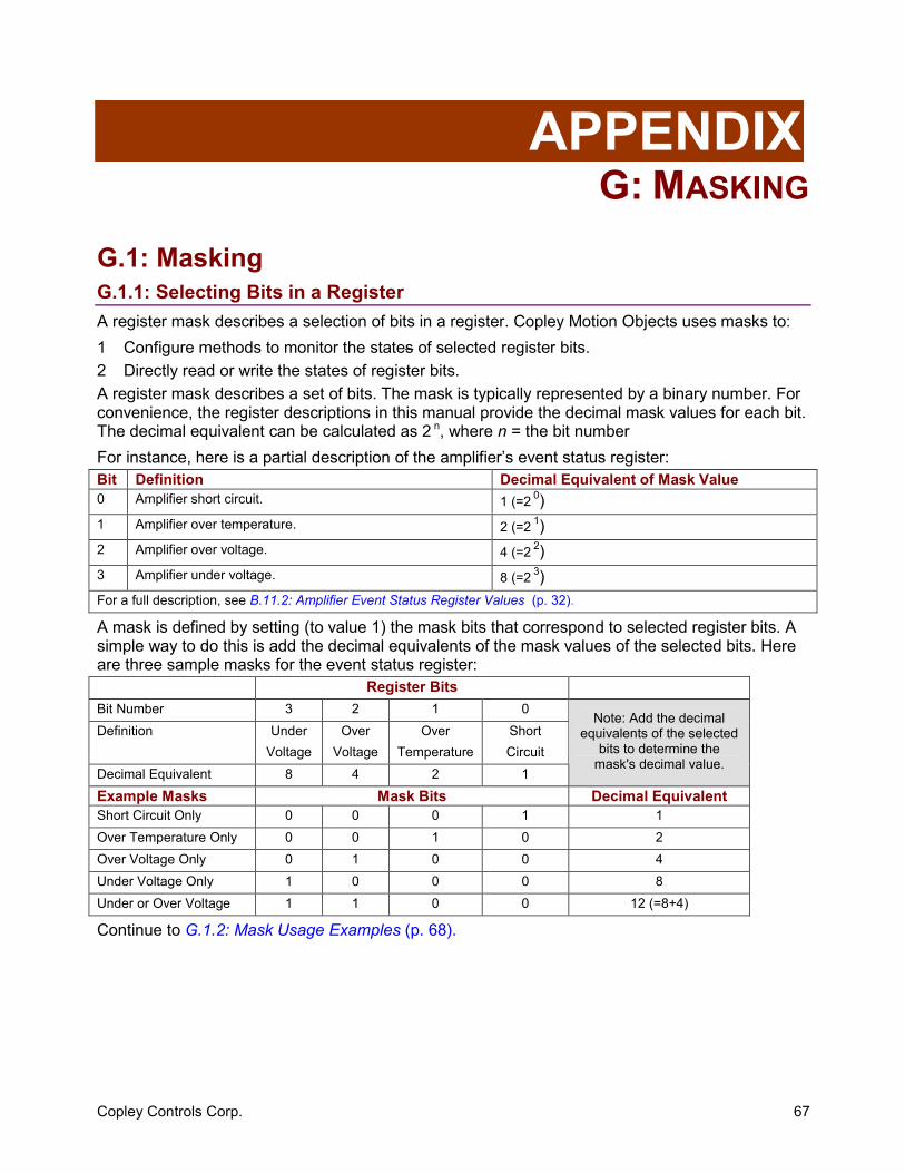
Copley Controls Corp. 67
APPENDIX G: MASKING
G.1: Masking G.1.1: Selecting Bits in a Register A register mask describes a selection of bits in a register. Copley Motion Objects uses masks to: 1 Configure methods to monitor the states of selected register bits. 2 Directly read or write the states of register bits. A register mask describes a set of bits. The mask is typically represented by a binary number. For convenience, the register descriptions in this manual provide the decimal mask values for each bit. The decimal equivalent can be calculated as 2 n, where n = the bit number For instance, here is a partial description of the amplifier’s event status register: Bit Definition Decimal Equivalent of Mask Value 0 Amplifier short circuit. 1 (=2 0)1 Amplifier over temperature. 2 (=2 1)2 Amplifier over voltage. 4 (=2 2)3 Amplifier under voltage. 8 (=2 3)For a full description, see B.11.2: Amplifier Event Status Register Values (p. 32).
A mask is defined by setting (to value 1) the mask bits that correspond to selected register bits. A simple way to do this is add the decimal equivalents of the mask values of the selected bits. Here are three sample masks for the event status register: Register Bits Bit Number 3 2 1 0 Definition Under
Voltage Over
Voltage Over
Temperature Short Circuit
Decimal Equivalent 8 4 2 1
Note: Add the decimal equivalents of the selected
bits to determine the mask's decimal value.
Example Masks Mask Bits Decimal Equivalent Short Circuit Only 0 0 0 1 1 Over Temperature Only 0 0 1 0 2 Over Voltage Only 0 1 0 0 4 Under Voltage Only 1 0 0 0 8 Under or Over Voltage 1 1 0 0 12 (=8+4)
Continue to G.1.2: Mask Usage Examples (p. 68).
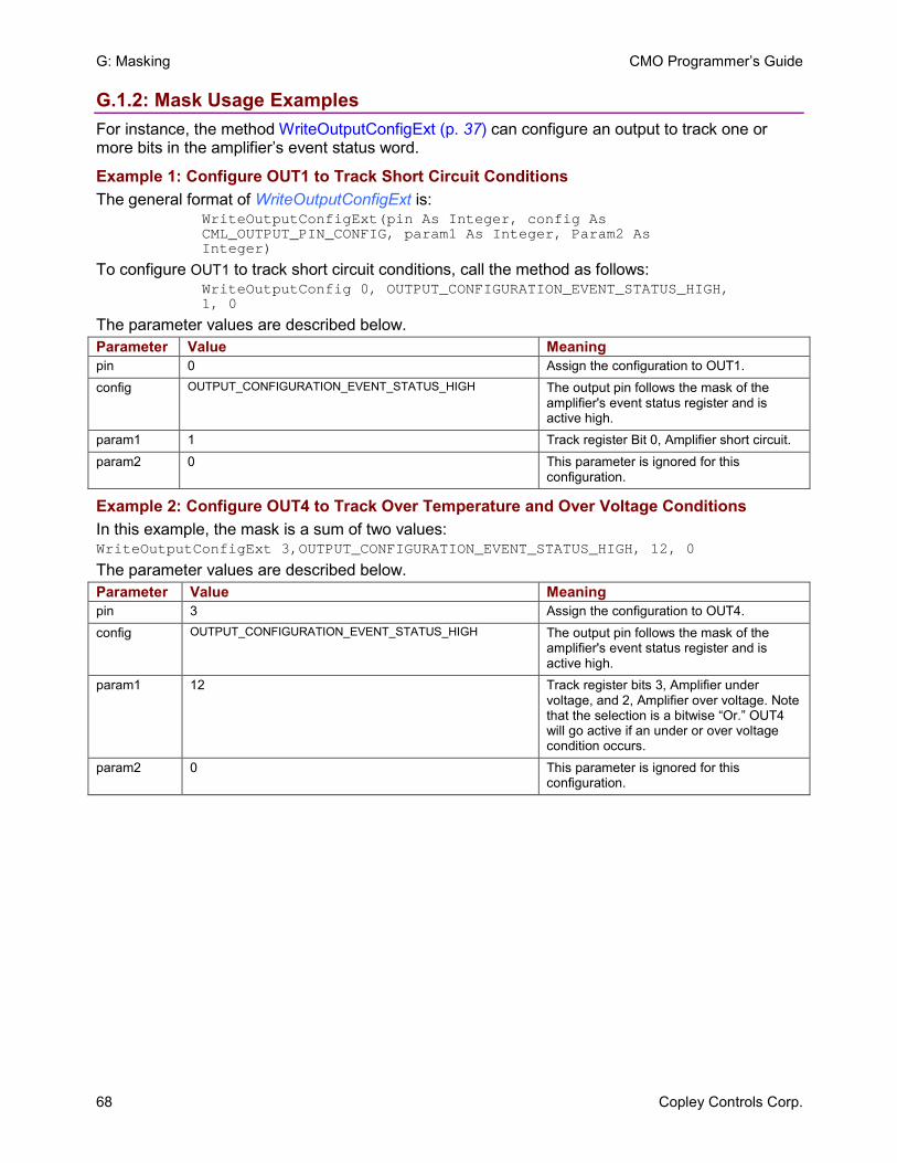
G: Masking CMO Programmer’s Guide
68 Copley Controls Corp.
G.1.2: Mask Usage Examples For instance, the method WriteOutputConfigExt (p. 37) can configure an output to track one or more bits in the amplifier’s event status word.
Example 1: Configure OUT1 to Track Short Circuit Conditions The general format of WriteOutputConfigExt is:
WriteOutputConfigExt(pin As Integer, config As CML_OUTPUT_PIN_CONFIG, param1 As Integer, Param2 As Integer)
To configure OUT1 to track short circuit conditions, call the method as follows: WriteOutputConfig 0, OUTPUT_CONFIGURATION_EVENT_STATUS_HIGH, 1, 0
The parameter values are described below. Parameter Value Meaning pin 0 Assign the configuration to OUT1. config OUTPUT_CONFIGURATION_EVENT_STATUS_HIGH The output pin follows the mask of the
amplifier's event status register and is active high.
param1 1 Track register Bit 0, Amplifier short circuit. param2 0 This parameter is ignored for this
configuration.
Example 2: Configure OUT4 to Track Over Temperature and Over Voltage Conditions In this example, the mask is a sum of two values: WriteOutputConfigExt 3,OUTPUT_CONFIGURATION_EVENT_STATUS_HIGH, 12, 0
The parameter values are described below. Parameter Value Meaning pin 3 Assign the configuration to OUT4. config OUTPUT_CONFIGURATION_EVENT_STATUS_HIGH The output pin follows the mask of the
amplifier's event status register and is active high.
param1 12 Track register bits 3, Amplifier under voltage, and 2, Amplifier over voltage. Note that the selection is a bitwise “Or.” OUT4 will go active if an under or over voltage condition occurs.
param2 0 This parameter is ignored for this configuration.
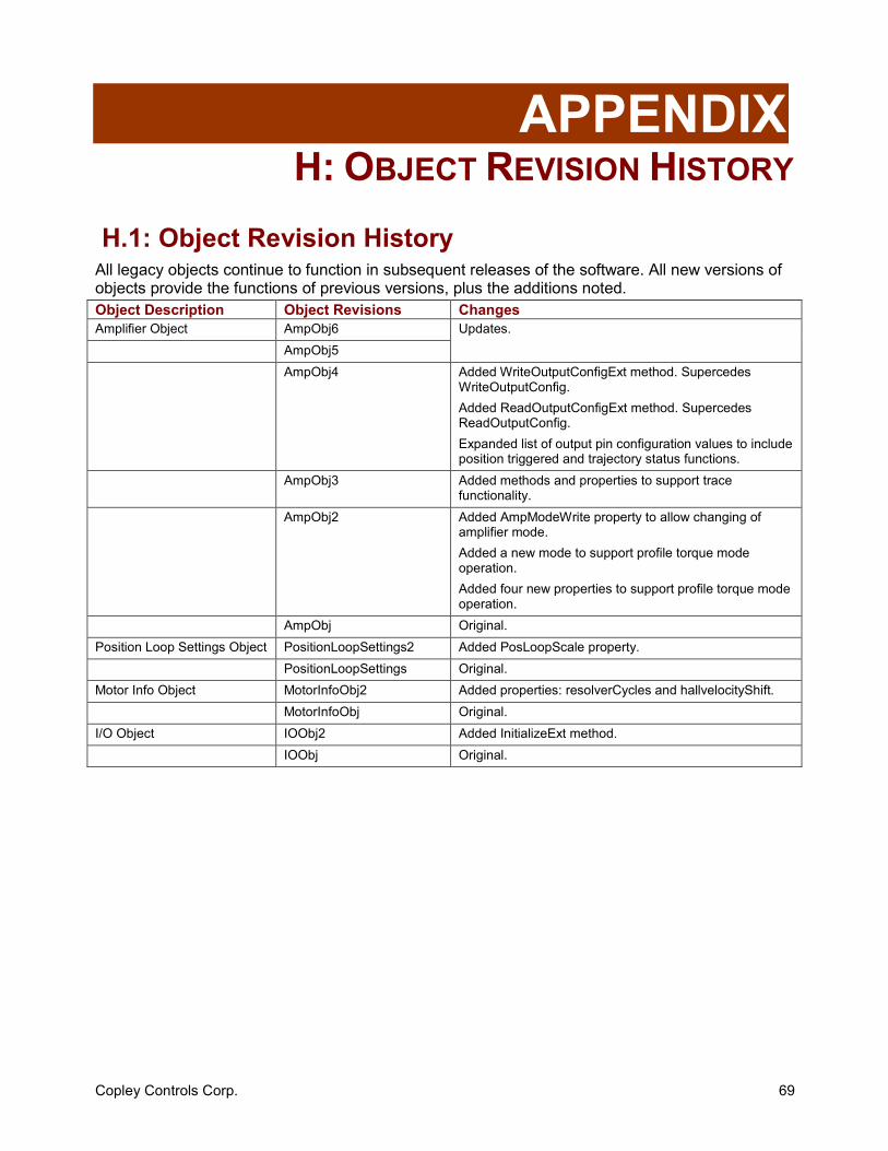
Copley Controls Corp. 69
APPENDIX H: OBJECT REVISION HISTORY
H.1: Object Revision History All legacy objects continue to function in subsequent releases of the software. All new versions of objects provide the functions of previous versions, plus the additions noted. Object Description Object Revisions Changes Amplifier Object AmpObj6
AmpObj5 Updates.
AmpObj4 Added WriteOutputConfigExt method. Supercedes WriteOutputConfig. Added ReadOutputConfigExt method. Supercedes ReadOutputConfig. Expanded list of output pin configuration values to include position triggered and trajectory status functions.
AmpObj3 Added methods and properties to support trace functionality.
AmpObj2 Added AmpModeWrite property to allow changing of amplifier mode. Added a new mode to support profile torque mode operation. Added four new properties to support profile torque mode operation.
AmpObj Original. Position Loop Settings Object PositionLoopSettings2 Added PosLoopScale property.
PositionLoopSettings Original. Motor Info Object MotorInfoObj2 Added properties: resolverCycles and hallvelocityShift.
MotorInfoObj Original. I/O Object IOObj2 Added InitializeExt method.
IOObj Original.
Copley Motion Objects (CMO) Programmer’s Guide P/N 95-00290-000
Revision 4 June 2008
2004-2008 Copley Controls Corporation
20 Dan Road Canton, MA 02021 USA
All rights reserved