Coordinate - Northern Arizona University · 1 Coordinate Systems 1. Geographic coordinate system To...
10
1 Coordinate Systems 1. Geographic coordinate system To locate a point on a piece of white paper, we usually use the distances of the point to the left/right edge (x) and top/bottom edge (y). Therefore the edges (left/right, top/bottom) are references for locating positions in the paper space. It is a little challenging suppose you are to describe a point on the surface of a basketball. Fortunately, the earth spins around an axis which provides a hint for defining a reference system. The largest circle around the axis (the equator) can serve as one reference (latitude). But we still need another reference (longitude) so as to define unique locations on the earth surface. Since 1870, geographers and scientists of allied disciplines from all nations have been trying the possibility of fixing a common zero for longitude and time reckoning throughout the globe. And it was the Prime Meridian, which was the first to be discussed. Hipparchos was the first astronomer to determine the differences in longitude, of which he used Rhodes. Ptolemy , following the Marinus of Tyre, adopted a meridian through the Canary Islands, which marked the western boundary of the world, whereas, to the east, there seemed to be no such boundary. In 1871 the first International Geographical Congress (IGC) took place at Antwerp. The view expressed was for passage charts for all nations, not necessarily coastal or harbour charts, the Greenwich meridian should be adopted as the common zero for longitude, and that this should become obligatory within fifteen years. It was also recommended that, whenever ships exchanged longitudes at sea, they should be based on Greenwich. This did not apply to land maps and coastal charts, these should keep its own prime meridian. Equator Prime meridian
Transcript of Coordinate - Northern Arizona University · 1 Coordinate Systems 1. Geographic coordinate system To...

1
Coordinate Systems 1. Geographic coordinate system To locate a point on a piece of white paper, we usually use the distances of the point to the left/right edge (x) and top/bottom edge (y). Therefore the edges (left/right, top/bottom) are references for locating positions in the paper space. It is a little challenging suppose you are to describe a point on the surface of a basketball.
Fortunately, the earth spins around an axis which provides a hint for defining a reference system. The largest circle around the axis (the equator) can serve as one reference (latitude). But we still need another reference (longitude) so as to define unique locations on the earth surface.
Since 1870, geographers and scientists of allied disciplines from all nations have been trying the possibility of fixing a common zero for longitude and time reckoning throughout the globe. And it was the Prime Meridian, which was the first to be discussed. Hipparchos was the first astronomer to determine the differences in longitude, of which he used Rhodes. Ptolemy , following the Marinus of Tyre, adopted a meridian through the Canary Islands, which marked the western boundary of the world, whereas, to the east, there seemed to be no such boundary.
In 1871 the first International Geographical Congress (IGC) took place at Antwerp. The view expressed was for passage charts for all nations, not necessarily coastal or harbour charts, the Greenwich meridian should be adopted as the common zero for longitude, and that this should become obligatory within fifteen years. It was also recommended that, whenever ships exchanged longitudes at sea, they should be based on Greenwich. This did not apply to land maps and coastal charts, these should keep its own prime meridian.
Equator Prim
e meridian

2
However, the 2nd IGC in Rome in 1875 discussed the whole matter again without coming to any further conclusions. France did express that if we were to accept the metric system, then they would accept the Greenwich meridian. Eventually, it was agreed internationally that a prime meridian was needed, and that it should be Greenwich.
So after years of discussion, the conference hoped that if the entire world was to accept Greenwich as the prime meridian, Great Britain might be prepared to conform to the metric system.
Greenwich Prime Meridian

3
Students, Lindsey Kordis and Anne Vest, stand in two hemispheres! With the equator and prime meridian, we can locate any position on the earth’s surface uniquely by recording its latitude and longitude. The latitude and longitude coordinate system is called geographic coordinate system. Many GIS products store locations as numbers using latitude and longitude or geographic coordinates. Latitudes go from 0 degree on the equator towards +90 degrees at the north pole and -90 degrees at the south pole. Longitudes go from 0 degree at the prime meridian towards +180 degrees eastwardly and -180 degrees westwardly. Values of latitudes and longitudes are recorded either in degree, minute, and second (e.g., 43º19´28˝, 84º40´59˝), or simply in decimal degrees (e.g., 43.324344232º, -84.6829432432º). The advantage of using geographic coordinates in a GIS is that all maps can be transformed into the same way. Moreover, almost all GIS products provide coordinate system conversion from geographic coordinate system to other coordinate systems.

4
Furthermore, distances (especially long distances) measured in geographic coordinate system can take into account the curvature of the earth surface, therefore, are more accurate then other coordinate systems. 2. Universal Transverse Mercator (UTM) Coordinate System The universal transverse Mercator (UTM) coordinate syatem is commonly used in GIS because it has been included since the late 1950s on most USGS topographic maps. It is sometimes referred as Gauss-Kruger coordinate system in other countries. The Universal Transverse Mercator system is a specialized application of the Transverse Mercator projection. The globe is divided into 60 north and south zones, each spanning six degrees of longitude. Each zone has its own central meridian. Zones 1N and 1S start at -180° W. The limits of each zone are 84° N and 80° S, with the division between north and south zones occurring at the equator. The polar regions use the Universal Polar Stereographic coordinate system. The origin for each zone is its central meridian and the equator. To eliminate negative coordinates, the coordinate system alters the coordinate values at the origin. The value given to the central meridian is the false easting, and the value assigned to the equator is the false northing. A false easting of 500,000 meters is applied. A north zone has a false northing of zero, while a south zone has a false northing of 10,000,000 meters.

5
PROJECTION METHOD Cylindrical projection. See the Transverse Mercator projection for the methodology. LINES OF CONTACT Two lines parallel to and approximately 180 km to each side of the central meridian of the UTM zone. PROPERTIES Shape Conformal. Accurate representation of small shapes. Minimal distortion of larger shapes within the zone. Area Minimal distortion within each UTM zone. Direction Local angles are true. Distance

6
Scale is constant along the central meridian but at a scale factor of 0.9996 to reduce lateral distortion within each zone. With this scale factor, lines lying 180 km east and west of and parallel to the central meridian have a scale factor of one. LIMITATIONS Designed for a scale error not exceeding 0.1 percent within each zone. Error and distortion increase for regions that span more than one UTM zone. UTM is not designed for areas that span more than a few zones. Data on a spheroid or an ellipsoid cannot be projected beyond 90 degrees from the central meridian. In fact, the extent on a spheroid or ellipsoid should be limited to 15–20 degrees on both sides of the central meridian. Beyond that range, data projected to the Transverse Mercator projection may not project back to the same position. Data on a sphere does not have these limitations. USES AND APPLICATION Used for United States topographic quadrangles, 1:100,000 scale. Many countries use local UTM zones based on the official geographic coordinate systems in use. Large-scale topographic mapping of the former Soviet Union. 3. Military Grid Coordinate System
Military Grid is an extension of UTM. Zones are numbered as in the UTM from 1 to 60 west to east. Within zones, 8-degree strips of latitude are lettered from C (80 to 72 degrees south) to X (72 to 84 degrees north, the last strip is particularly extended). The letter designations A, B, Y and Z are reserved for Universal Polar Stereographic

7
designations on the poles. So each typical grid is 6 x 8 degrees. In this coordinate system, Flagstaff falls into grid 12S. Each grid cell is further subdivided into squares 100,000 meters on a side. Each cell is assigned two additional letter identifiers. In the east-west (x) direction, the 100,000 meter squares are lettered starting with A, up to Z., and then repeating around the world, with the exception that letters I and O are excluded, because they could be confused with numbers.
In the north-south (y) direction, the letters A through V are used (again omitting I and O), starting at the equator and increasing north, and again cycling through the letters as needed. The reverse sequence, starting V and cycling backward to A then back to V, and so on, is used for the southern hemisphere. Thus a single 100,000 meter grid square can be identified using a sequence such as 18TWC. Within this area, successively accurate locations can be given by more and more pairs of x and y digits. 4. State Plane Also known as SPCS, SPC, State Plane, and State. The State Plane is not a projection. It is a coordinate system that divides the 50 states of the United States, Puerto Rico, and the U.S. Virgin Islands into more than 120 numbered sections, referred to as zones. Each zone has an assigned code number that defines the projection parameters for the region. PROJECTION METHOD
8
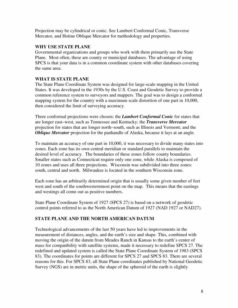
Projection may be cylindrical or conic. See Lambert Conformal Conic, Transverse Mercator, and Hotine Oblique Mercator for methodology and properties. WHY USE STATE PLANE Governmental organizations and groups who work with them primarily use the State Plane. Most often, these are county or municipal databases. The advantage of using SPCS is that your data is in a common coordinate system with other databases covering the same area. WHAT IS STATE PLANE The State Plane Coordinate System was designed for large-scale mapping in the United States. It was developed in the 1930s by the U.S. Coast and Geodetic Survey to provide a common reference system to surveyors and mappers. The goal was to design a conformal mapping system for the country with a maximum scale distortion of one part in 10,000, then considered the limit of surveying accuracy. Three conformal projections were chosen: the Lambert Conformal Conic for states that are longer east–west, such as Tennessee and Kentucky; the Transverse Mercator projection for states that are longer north–south, such as Illinois and Vermont; and the Oblique Mercator projection for the panhandle of Alaska, because it lays at an angle. To maintain an accuracy of one part in 10,000, it was necessary to divide many states into zones. Each zone has its own central meridian or standard parallels to maintain the desired level of accuracy. The boundaries of these zones follow county boundaries. Smaller states such as Connecticut require only one zone, while Alaska is composed of 10 zones and uses all three projections. Wisconsin was subdivided into three zones: south, central and north. Milwaukee is located in the southern Wisconsin zone. Each zone has an arbitrarily determined origin that is usually some given number of feet west and south of the southwesternmost point on the map. This means that the eastings and westings all come out as positive numbers. State Plane Coordinate System of 1927 (SPCS 27) is based on a network of geodetic control points referred to as the North American Datum of 1927 (NAD 1927 or NAD27). STATE PLANE AND THE NORTH AMERICAN DATUM Technological advancements of the last 50 years have led to improvements in the measurement of distances, angles, and the earth’s size and shape. This, combined with moving the origin of the datum from Meades Ranch in Kansas to the earth’s center of mass for compatibility with satellite systems, made it necessary to redefine SPCS 27. The redefined and updated system is called the State Plane Coordinate System of 1983 (SPCS 83). The coordinates for points are different for SPCS 27 and SPCS 83. There are several reasons for this. For SPCS 83, all State Plane coordinates published by National Geodetic Survey (NGS) are in metric units, the shape of the spheroid of the earth is slightly

9
different, some states have changed the definition of their zones, and values of longitude and latitude are slightly changed. UNIT OF LENGTH The standard unit of measure for SPCS 27 is the U.S. Survey foot. For SPCS 83, the most common unit of measure is the meter. Those states that support both feet and meters have legislated which feet-to-meters conversion they use. The difference between the two is only two parts in one million, but that can become noticeable when datasets are stored in double precision. The U.S. Survey foot equals 1,200/3,937 m, or 0.3048006096 m. Advantages: very high location precision for large scale (small area) maps; the distortion in area, direction and length are minimal. Disadvantage: lack of universality. Maps for adjacent areas but in different zones cannot be put together for analysis.
State Plane Coordinate Systems of SW US
10
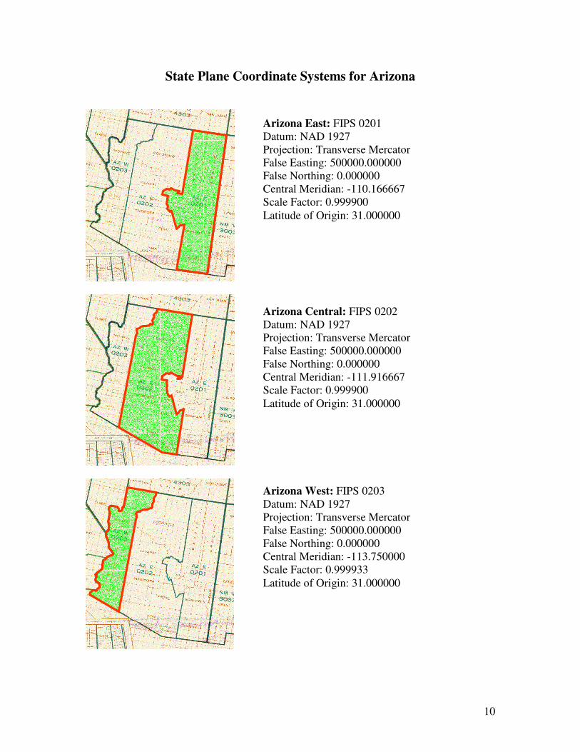
State Plane Coordinate Systems for Arizona
Arizona East: FIPS 0201 Datum: NAD 1927 Projection: Transverse Mercator False Easting: 500000.000000 False Northing: 0.000000 Central Meridian: -110.166667 Scale Factor: 0.999900 Latitude of Origin: 31.000000
Arizona Central: FIPS 0202 Datum: NAD 1927 Projection: Transverse Mercator False Easting: 500000.000000 False Northing: 0.000000 Central Meridian: -111.916667 Scale Factor: 0.999900 Latitude of Origin: 31.000000
Arizona West: FIPS 0203 Datum: NAD 1927 Projection: Transverse Mercator False Easting: 500000.000000 False Northing: 0.000000 Central Meridian: -113.750000 Scale Factor: 0.999933 Latitude of Origin: 31.000000