Impairment-Aware Routing and Wavelength Assignment (IA-RWA )
1
Cooperative Routing with Relay Assignment inMulti-radio Multi-hop Wireless Networks
Kun Xie1,2,3, Xin Wang3, Jigang Wen4, and Jiannong Cao51 College of Computer Science and Electronics Engineering, Hunan University, Changsha, China
2 State key Laboratory of Networking and Switching Technology, Beijing Univ. of Posts and Telecomm., China3 Department of Electrical and Computer Engineering, State University of New York at Stony Brook, USA
4 Institute of Computing Technology, Chinese Academy of Science, China5 Department of computing, The Hong Kong Polytechnic University, Hong Kong
[email protected], [email protected], [email protected], [email protected]
Abstract—Cooperative communication (CC) for wireless net-works has gained a lot of recent interests. It has been shownthat CC has the potential to significantly increase the capacityof wireless networks, with its ability of mitigating fading byexploiting spatial diversity. However, most of the works on CCare limited to single radio wireless network. To demonstrate thebenefits of CC in multi-radio multi-hop wireless network, thispaper studies a joint problem of multi-radio cooperative routingand relay assignment to maximize the minimum rate among aset of concurrent communication sessions. We first model thisproblem as a mixed integer programming (MIP) problem andprove it to be NP-hard. Then we propose a centralized algorithmand a distributed algorithm to solve the problem. The centralizedalgorithm is designed within a branch-and-bound frameworkby using the relaxation of the formulated MIP, which can finda global (1 + ε)-optimal solution. Our distributed algorithmincludes two sub-algorithms: a cooperative route selection sub-algorithm and a fairness-aware route adjustment sub-algorithm.Our simulation results demonstrate the effectiveness of theproposed algorithms and the significant rate gains that can beachieved by incorporating CC in multi-radio multi-hop networks.
I. INTRODUCTIONIn recent years, we have seen significant research interests in
exploiting cooperative communications (CC) over distributedantennas to improve the transmission performance [1]. Takingadvantage of the broadcast nature of wireless channels, oneor more neighboring nodes can serve as relays and forwardoverheard packets from a sender to its target receiver, whichcan combine multiple copies of the packet to decode theoriginal one. Therefore, by exploiting the inherent spatialand multiuser diversities, the cooperative communication tech-nique can efficiently improve the network performance. Thismakes cooperative communications an emerging technique forfuture wireless networks.
Existing studies on CC are mostly based on the single radionetworks [2]–[14]. With the constant reduction of hardwarecost and the availability of cheap, off-the-shelf commodityhardware equipped with multiple radios, more and morewireless devices are equipped with multi-radio communicationinterfaces. This not only brings in the extra capacity gain for asingle device and a wireless network formed with multi-radionodes, but also creates more opportunities for cooperative
communications. Although promising, there are very limitedstudies on exploiting the multi-radio capabilities for flexiblecooperative communication to improve the multi-radio multi-hop wireless network performance.
This paper intends to provide some design guideline anddemonstrate the benefits of CC in multi-radio multi-hopwireless networks. The existence of multi-radio devices inthe network allows for more transmission opportunities andflexibilities, but also leads to more challenges in networkdesign, especially the enabling of cooperative communicationsin multi-radio multi-hop networks.
With more radio interfaces, a node in the network can actnot only as a cooperative relay for CC but also a transmissionrelay for multi-hop packet forwarding. The first challengingissue is how to assign relay nodes (either for CC or as amulti-hop relay) for each session. Fig. 1 shows examplesof cooperative communication with each node equipped withtwo radios, where the dashed lines represent cooperativetransmissions. In Fig. 1(a), the node r could use one radioas cooperative relay for session s1 → d1, and the other radioas cooperative relay for session s2 → d2. In Fig. 1(b), thenode r could use one radio as cooperative relay for sessions2 → d2, and the other radio as a multi-hop relay for sessions1 → d1.
The capability for a node or a radio interface to serve as twodifferent types of relay makes multi-radio cooperative routingand relay node assignment inter-dependent. The second chal-lenging issue is how to solve the coupled multi-radio routingproblem and relay assignment problems optimally togetherwhile taking into account the wireless interference arisen fromboth direct transmission and cooperative communication.
d1
d2
s1
s2r
(a)
d1
d2
s1
s2
r
(b)
Fig. 1. CC in multi-radio multi-hop wireless network.

To address the above challenging issues, the aim of thiswork is to solve a joint problem of multi-radio cooperativerouting and relay assignment to understand the benefits ofapplying CC in multi-radio multi-hop wireless networks. Com-pared to conventional single-radio CC studies, the introductionof multi-radio nodes significantly increases the flexibility inrelay selection thus the performance gain as demonstrated inour performance evaluations. However, this also makes theproblem much harder to solve. The objective of our work isto maximize the minimum rate among a set of concurrentcommunication sessions to increase the transmission fair-ness by considering the opportunities brought by cooperativecommunications and the limitation of the number of radiosat network nodes. Our contributions can be summarized asfollows:
• We first model the problem as a mixed integer program-ming (MIP) problem and prove it to be an NP-hardproblem.
• To efficiently solve the problem, we propose a distributedalgorithm with two steps. In the first step, an interference-aware cooperative route selection algorithm is proposedto select an optimal routing path with the maximum ca-pacity for each newly arrival session. In the second step,a fairness-aware algorithm is proposed to adjust the pathlocally around the link overloaded with transmissionsfrom multiple sessions.
• For performance reference, based on the relaxation ofthe formulated MIP, we propose a centralized algorithmwithin a branch-and-bound framework to provide aneffective global (1 + ε)-optimal solution where ε is adesired approximation error bound.
We have carried out extensive simulations to evaluate theperformance of our proposed algorithms. The simulation re-sults demonstrate the effectiveness of our algorithms and thesignificant rate gains that can be achieved by incorporating CCin multi-radio multi-hop networks.
The rest of this paper is organized as follows: Section IIpresents related work. Section III describes the system model.In Section IV, we model this problem as a mixed integerprogramming (MIP) problem and prove it to be a NP-hardproblem. We propose a distributed algorithm and a centralizedalgorithm to solve the problem in Section VI and SectionV, respectively. Section VII presents simulation results todemonstrate the rate gains that can be achieved by exploitingCC in multi-radio multi-hop wireless networks. We concludethis paper in Section VIII.
II. RELATED WORK
We are not aware of any other work that concurrentlyconsiders interference aware cooperative routing and relayassignment for performance enhancement in multi-radio multi-hop wireless networks. Following we review some literaturework that has certain parts relevant to our work.A. Cooperative Communications
Cooperative communication is a physical layer technique.Built upon the work at the physical layer [15]–[19], appli-cations and network protocols have mushroomed in single-
radio wireless networks recently, either single-radio single-hopnetwork [2]–[7] or single-radio multi-hop network [8]–[14].
The research focus of CC in single-radio single-hop wire-less network is on the selection of the relay for a source-destination pair and resource allocation for the selected relay.In [2], Cai et al. study the problem of relay selection andpower allocation, first over a simple network with only onesource node, and then extending to the multiple-source case.In [3], the authors propose a distributed buyer/seller gametheoretic framework over multiuser CC networks to stimulatecooperation and improve the system performance. In [4],Shi et al. study the relay assignment problem such that theminimum capacity among all source nodes is maximized. Theypropose an optimal polynomial time algorithm to solve theproblem. Following this work, the authors in [5] study therelay assignment problem with interference mitigation. Aimingat maximizing network throughput with proportional fairness,the authors in [6] have investigated the joint relay selection andlink scheduling problem in a relay-assisted wireless cellularnetwork. The work in [7] targets to solve the relay assignmentproblem for maximizing the total capacity of all pairs in amore general sense where multiple source nodes can sharesame relay node.
However, the above studies for single-radio single-hop wire-less network cannot be easily extended to a multi-hop wirelessnetwork.
There are some studies of CC in single-radio multi-hopwireless network. In [8], Khandani et al. study a minimumenergy routing problem in a static wireless network anddevelop a dynamic-programming-based algorithm for findingthe optimal route in an arbitrary network. However, theirapproach is limited to single session as opposed to multiplesessions that we have considered in this paper. In [9], Ed-mund et al. consider cooperative relay networks with multiplestochastically varying sessions, which may be queued withinthe network. Throughput optimal network control policiesare studied that take into account queue dynamics to jointlyoptimize routing, scheduling and resource allocation, withthe solutions constrained to the special case of parallel relaynetworks. The papers [10]–[12] propose heuristics schemesthat first develop routing solutions to find a primary path, andthen consider relay node assignment for CC according to theprimary path. However, these solutions decouple routing andrelay assignment, which makes the path found far from theoptimal one.
In [13], the authors propose a distributed cooperative routingalgorithm to construct a minimum-power route to guaranteecertain throughput. In [20], the authors define a bandwidthand power aware cooperative multi-path routing problemover wireless multimedia sensor networks, and propose apolynomial-time heuristic algorithm to solve the problem. In[14], to illustrate the benefits of CC in multi-hop wirelessnetworks, the authors solve a joint optimization problemof relay node assignment and flow routing for concurrentsessions.
The above results are restricted to a single-radio network.The presence of multi-radio nodes provides more opportunitiesfor network capacity enhancement, with the radios possibly
2

forwarding packets in the normal routing path or serving asrelays for cooperative communications. The determination ofthe optimal functions for the radios is a challenging problemand has very limited work. Only the work in [21] studies CCin multi-radio multi-hop networks. It proposes a channel-on-demand mathematical model to maximize the capacity, andprovides an optimal interface assignment algorithm for real-time flows. Different from our work in this paper, however, theapproach proposed is run with the assumption that the routingpath is given.
Therefore, current work on cooperative communications formulti-radio multi-hop wireless communication is very limited,which is the main focus of this paper.
Despite the wide interests, cooperative communications canlead to increased interference, which results in transmissionconflicts and data retransmission and consequently networkperformance degradation [22]. The interference problems havebeen noticed and studied by only a limited number of re-searchers [7], [23], [24]. Yang et al. [7] point out that the co-channel interference has become a prominent issue to applycooperative communication techniques in wireless networks.Zhang et al. [24] further show that the performance degrada-tion as a result of co-channel interference largely impacts theperformance of multi-hop wireless networks.
Li et al. [25] study an energy and spectrum efficient co-operative communication problem in a one-hop multi-channelwireless network. The objective of the work is to find theoptimal transmission power, relay assignment, and channelallocation such that the rate requirements of all users aresatisfied and the total energy consumption is minimized.Although the network has multiple channels, each node isassumed to have only a single radio and can only access onechannel at a time.
Considering only a simple network model, the solutions of[7], [22]–[25] are difficult to be extended to multi-radio multi-hop wireless networks to achieve the cooperative diversity gainin the presence of wireless interference.B. Multi-radio Technique
Many studies [26]–[30] have been made to exploit multi-radio and multi-channel (MRMC) technique to combat theincreased co-channel interference for higher network capacity.With multiple wireless radios (i.e., network interface card(NIC)), nodes within a neighborhood can send data throughorthogonal channels without transmission conflicts, whichleads to efficient spectrum utilization and increases the actualbandwidth available to the network.
Different from the above work which only considers con-ventional one-to-one direct transmission, cooperative commu-nications can potentially improve the network performanceby exploiting many-to-one transmissions to mitigate fading.The techniques proposed for direct transmissions can not beeasily applied in cooperative wireless networks to achieve thecooperative diversity gain.
As a multi-radio technique, MIMO can achieve spatialdiversity by employing multiple transmitter-receiver radio in-terfaces, which has attracted lots of interest recently [31]–[34]. The work in [31], [32] exploits the use of cooperative
relay transmission in a MIMO-based ad hoc network to copewith harsh channel condition, while authors in [33] proposeto deploy MIMO nodes as relays to assist weak links inwireless networks with the aim of reducing the number ofrelay nodes and providing performance provisioning. Theseefforts target to solutions at MAC layer scheduling and fordeployment respectively without considering the routing. Anode equipped with multiple radios does not ensure the nodeto form MIMO array and enjoy the MIMO benefits. Therefore,multi-radio communications and MIMO communications havebeen different research thrusts in the community.
To the best of our knowledge, this is the first work to demon-strate the benefits of CC in multi-radio multi-hop wirelessnetworks. This paper considers a joint problem of interference-aware cooperative routing and relay node assignment, andproposes both centralized and distributed algorithm to solvethe problem.
III. SYSTEMS MODEL
A. Network Scenario
We consider a multi-radio multi-channel multi-hop wirelessnetwork with n nodes contained in a set N , where each nodeis equipped with one or multiple wireless radios. There aremultiple concurrent sessions in the network, denoted by a setF = {f1, f2...fJ} of J . A session fi(si → di) goes throughthe source node si and the destination node di, and the datafor each session may traverse multiple hops in the network.
We assume that there are a total of l orthogonal channelsin the network, denoted by C={ch1, ch2, ..., chl}, and thereis no inter-channel interference. The set of working channelsassigned to node i is denoted as Ci. Due to the interferenceconstraints, there is no capacity benefit to assign two radiosof a node with the same channel.
There are two types of relay nodes on a path from the sourceto the destination of a session. The first type is CooperativeRelay (CR) which is used for CC purpose (i.e., node r7 ofsession 2 in Fig. 2). The second type is multi-hop Relay (MR)which operates at the network layer to relay the packets from asource over multiple hops to its destination (i.e., r6 of session2 in Fig. 2).
A node with multiple radios can serve as both CR and MRfor multiple sessions. Similarly, a source node (or a destinationnode) can serve as a CR or MR for other sessions, and a singleCR node can serve more than one session.
In the example of Fig. 2, there are three communicationsessions. The dashed line represents a relay path through aCR relay node which serves for the purpose of cooperativecommunication while the solid line represents the normal datatransmission path, and a node on the path serves as an MR. Arelay nods with multiple radios can serve for multiple sessionsand act in different roles (CR or MR) in different sessions. Forexample, node r3 is the CR of both session 1 and session 2,while node r4 is the CR of session 3 and is also used as anMR for the session 2. The node r5 is used as MR to carrytraffic for both sessions 1 and 3.
3

s2 d2
r1
r2
r3
r4
r5r6r7
s1
d1
s3
d3
r8
Cooperative relay
Multi-hop relay
Fig. 2. A multi-radio multi-hop network consisting of multiple sessions.
B. Two Kinds of Transmission ModesThere are two transmission modes between any two nodes
in the network considered, direct transmission (DT) and coop-erative transmission. A direct transmission is carried directlybetween two neighboring nodes i and j over one link, wherenode i is the sender and node j is the receiver (i.e.,s1 → r2in Fig. 2). The cooperative transmission between two nodes xand z involves three links (x, y), (x, z), and (y, z), where therelay node y acts as a CR relay for the transmission betweenx and z (i.e., r2 → r5(r3) in Fig. 2, where r3 is the CR relay).
ds
r
Fig. 3. A three-node CC model.
Fig. 3 shows a three-node CC model. In the cooperativetransmission, a collaborative neighbor r overhears the signalfrom the source s to the destination d and forwards it to d. dcombines two signal streams, s ⇒ d and r ⇒ d into a singlestream that has a higher resistance to channel fading and noiseand hence a higher probability of being successfully decoded.
A recent study [35] shows that the diversity gain achievedby exploiting multiple relay nodes is marginally higher thanthe diversity gain achieved by selecting the best relay. There-fore, we consider each hop of a session can select at most onerelay node for CC as done in other related work [13], [14],[25].
The mechanism to accomplish CC is not unique. Between sand d under CC, there are two typical cooperative transmissionmodes including amplify-and-forward (AF) and decode-and-forward (DF) modes [36]. In [37], authors describe andcompare the capacity of different cooperative transmissionprotocols and show that the AF-RAKE-based cooperativetransmission protocol can achieve the maximum capacity. InAF-RAKE, after receiving signals from s, r amplifies andforwards them to d without demodulation or decoding. d usesa RAKE receiver to combine both signal streams of s ⇒ d andr ⇒ d. The achievable rate under AF-RAKE mode betweens and d with r as the relay [37] is given by
C(s, d, r, CC) = W ∗ IAF (s, d, r), (1)
where
IAF (s, d, r) = log2(1 + SNRsd +SNRsr ∗ SNRrd
SNRsr + SNRrd + 1) (2)
SNRsd =Ps
σ2d
|hsd|2, SNRsr =Ps
σ2r
|hsr|2, SNRrd =Pr
σ2d
|hrd|2 .(3)
W is the available bandwidth of channels at nodes s and r,hsd, hsr, hrd represent the effects of path-loss, shadowing,and fading within its respective channel between nodes s andd, s and r, as well as r and d, respectively. σ2
d and σ2r denote
variance of the zero-mean background noise at nodes d andr, while Ps and Pr denote the transmission powers at nodess and r respectively.
For the direct transmission mode, the achievable rate be-tween s and d is expressed as
C(s, d,DT ) = W log2(1 + SNRsd) (4)
IV. PROBLEM DESCRIPTION
In multi-flow multi-radio multi-hop wireless networks, arelay node with multiple radios can be shared and serve formultiple sessions, as shown in Fig.1. A challenging problemis how to efficiently assign relay nodes for each sessionwhile taking account of wireless interference from both directtransmission and cooperative communication.
In our problem formulation, we will jointly consider co-operative routing and relay assignment under three types ofconstraints: the constraint on relay nodes, the constraint onflow routing, and the constraint on link capacity. Followingwe first introduce the constraints.
Let a binary variable Akuv denote whether there is a link
u → v through the channel chk. For direct communication,the receiver v needs to be within the communication range ofthe sender u, with u and v sharing a common channel:
Akuv =
{1 v ∈ N(u) and k ∈ Cu ∩ Cv, u ̸= v0 otherwise
(5)
where N(u) denotes the one-hop neighbor set of node u.We consider the three links for cooperative communication
(i.e., from the sender to the receiver, from the sender tothe relay, and from the relay to the receiver) as a virtualcooperative link, with the sender, relay, and the receiverassigned with a common channel. A binary variable Bwk
uv
denotes whether there is a virtual cooperative link u → v(w)through the channel chk and the relay w:
Bwkuv =
1v ∈ N(u) and w ∈ N(u) ∩N(v)and k ∈ Cu ∩ Cv ∩ Cw, w ̸= u,w ̸= v
0 otherwise(6)
We further define a binary variable ykj:uv to denote whetheror not a direct link u → v |chk is selected by the session j:
ykj:uv =
{1 link u → v |chk is selected by session j0 otherwise
(7)
4

Similarly, we define a binary variable xwkj:uv to indicate
whether or not a virtual cooperative link u → v(w) |chk isselected by session j:
xwkj:uv =
{1 link u → v(w) |chk is selected by session j0 otherwise
(8)
A. Constraint on Relay NodesFor each hop (u, v), node u can transmit data to node v
through either direct transmission or cooperative transmission:∑w∈N
xwkj:uv + yk
j:uv ≤ 1 (j ∈ F, k ∈ C) (9)
B. Constraint on Flow RoutingGiven a session, a direct link is formed between only one
transmitter and one receiver:
∑k∈Cu∩Cv
u̸=v∑u∈N
ykj:uv ≤ 1 (j ∈ F , v ̸= sj) (10)
∑k∈Cu∩Cv
v ̸=u∑v∈N
ykj:uv ≤ 1 (j ∈ F , u ̸= dj) (11)
Similarly, a virtual cooperative link is also formed betweenone transmitter and one receiver:
∑k∈Cu∩Cv
u ̸=v,u ̸=w∑u∈N
xwkj:uv ≤ 1 (j ∈ F , v ̸= sj) (12)
∑k∈Cu∩Cv
v ̸=u,v ̸=w∑v∈N
xwkj:uv ≤ 1 (j ∈ F , u ̸= dj) (13)
Denote fkj:uv and fwk
j:uv as a session j’s flow rate on the directlink u → v |chk and virtual cooperative link u → v(w) |chk ,respectively. For an intermediate node, the outgoing flow rateshould be equal to the incoming flow rate:
∑k∈Cu∩Cw
u ̸=w,u̸=dj∑u∈N
(ykj:uwf
kj:uw +
t ̸=u,t̸=w∑t∈N
xtkj:uwf
tkj:uw
)=
∑k∈Cw∩Cv
v ̸=w,v ̸=sj∑v∈N
(ykj:wvf
kj:wv +
t̸=v,t̸=w∑t∈N
xtkj:wvf
tkj:wv
)(j ∈ F,w ∈ N,w ̸= sj , w ̸= dj)
(14)
Each hop (u, v) can transmit data using either direct trans-mission or cooperative transmission, thus a session’s outgoinglink and incoming link can be either a direct link or a virtualcooperative link. Therefore, the two side of (14) can have atmost one non-zero term. On the left side of Eq.(14), becauseof the constraint in Eq(9), if the incomming link exploitsdirect transmission, then ykj:uw = 1 and the term ykj:uwf
kj:uw is
non-zero and the termt ̸=u,t ̸=w∑
t∈N
xtkj:uwf
tkj:uw is zero. Otherwise
if the incomming link exploits the cooperative transmission,t ̸=u,t ̸=w∑
t∈N
xtkj:uw = 1 and the term
t ̸=u,t ̸=w∑t∈N
xtkj:uwf
tkj:uw is non-
zero and ykj:uw = 0 and the term ykj:uwfkj:uw is zero.
Similarly, on the right side of Eq.(14), if the outgoing linkexploits direct transmission, then ykj:wv = 1 and the termykj:wvf
kj:wv is non-zero. Otherwise if the outgoing link exploits
cooperative transmission, then∑t∈N
xtkj:wv = 1 and the term
t ̸=v,t ̸=w∑t∈N
xtkj:wvf
tkj:wv is non-zero.
C. Constraint on Link CapacityWe denote by RI the interference range, which is q × RT
where q ≥ 1 and RT is the communication range. A com-munication between u and v may block other transmissionswithin the RI range of either u or v.
In particular, we have the following two principles toidentify whether two links in a cooperative wireless networkinterfere with each other or not.
Principle 1. For direct transmissions, we consider a linkA → B to be the interference link of another link C → D ifA and B work on the same channel of C and D, and at leastone of the node pairs, pair(A,C), pair(A,D), pair(B,C), andpair(B,D) is within RI .
Principle 2. If node A transmits data to node B with thehelp of a cooperative relay R, we consider the cooperativelink A → B (R) to interfere with another link C → D ifA, B, and R work on the same channel of C and D, and atleast one of the node pairs, pair(A,C), pair(A,D), pair(B,C),pair(B,D), pair(R,C), and pair(R,D) is within RI .
According to the TDMA schedule adopted in the MAClayer, if a channel is equally shared among competing links,the available capacity of a direct transmission link u → v |chk
can be calculated as
Ck (u, v,DT ) =C (u, v,DT )
|Ik (u, v)|+ 1(15)
where C (u, v,DT ) (calculated by (4)) is the link capacity ofa direct link, Ik(u, v) denotes the link set that interferes withthe link u → v |chk , |Ik (u, v)| denotes the size of Ik(u, v).
The available capacity of a virtual cooperative link u →v(w) |chk can be calculated as
Ck (u, v, w,CC) =C (u, v, w,CC)
|Ik (u, v, w)|+ 1(16)
where C (u,w, v, CC) (calculated by (1)) is the link capacityof a virtual cooperative link, Ik(u, v, w) denotes the link setthat interfere with this virtual cooperative link.
Depending on whether a link being direct or cooperative,the capacity constraint for the aggregate flows traversing thelink through chk must not exceed the link capacity as follows:∑
j∈F
fkj:uv ≤ Ck (u, v,DT ) (17)
∑j∈F
fwkj:uv ≤ Ck (u, v, w,CT ) (18)
D. Problem FormulationThe objective of this paper is to maximize the minimum
flow rate among all active flows via interference-aware co-operative routing and relay assignment. Following the flowconstraint in (14), although a session may traverse multiplehops, the flow rate of every hop in the session is the same.Therefore, we use the rate of the first hop to denote the flow
5

rate. More formally, for a given session (sj , dj), denote theend-to-end flow rate (or throughput) as Rj , where
Rj =∑
k∈Csj∩Cv
v ̸=sj∑v∈N
ykj:sjvf
kj:sjv +
t̸=v,t ̸=sj∑t∈N
xtkj:sjvf
tkj:sjv
(19)
Let Rmin demote the minimum flow rate among all flows, i.e.,
Rmin = minj∈F
Rj (20)
Our objective is to maximize Rmin as follows:
Max Rmin
s.t. (9)(11)(10)(13)(12)(14)(17)(18)Rmin, f
kj:uv, f
wkj:uv ≥ 0(j ∈ F, k ∈ C, u, v, w ∈ N,w ̸= u,w ̸= v)
xwkj:uv, y
kj:uv ∈ {0, 1} (j ∈ F, k ∈ C, u, v, w ∈ N,w ̸= u,w ̸= v)
(21)where Rmin, fk
j:uv, fwkj:uv, xwk
j:uv and ykj:uv are optimizationvariables.
Theorem 1: The max-min cooperative routing problem incooperative wireless networks defined in (21) is NP-hard.
Proof: Although a cooperative transmission consists ofthree links, as mentioned earlier, we treat them as a virtualcooperative link. Multiple sessions can be transmitted concur-rently over different channels. After these simplification, themax-min cooperative routing problem can be translated to anun-splittable max-min bandwidth allocation problem, which isa known NP-hard problem [38].
V. DISTRIBUTED ALGORITHM
For practical implementation of cooperative communicationin multi-radio multi-channel multi-hop wireless networks, wepropose a Distributed joint Flow Routing and Relay nodeAssignment algorithm (DFRRA), which includes two steps.In the first step, an interference-aware Cooperative RouteSelection algorithm (CRS) is proposed to select an optimalcooperative routing path. In the second step, a Fairness AwareRouting Adjustment algorithm (FARA) is proposed to adaptthe route locally by considering the link competition amongmultiple sessions.A. Distributed Cooperative Route Selection Algorithm
For each active session, our proposed CRS will searchfor a routing path with the maximum end-to-end capacitytaking into account the wireless interference. In a cooperativenetwork, a cooperative path could be formed with a combi-nation of cooperative transmissions and direct transmissions,as shown in Fig.4. This makes the path finding difficult. Foreach transmission hop, CRS not only needs to select theforwarding node and the working channel of each hop but alsoto determine the transmission mode as well as the relay nodein case that a cooperative transmission mode is the option.
1) Routing MetricTo facilitate path selection, we define a routing metric of
a hop (x, y) as the maximum available capacity among allpossible channels through two possible transmission modes
CMetric(x, y) = maxchk∈Cx∩Cy,mode∈DT,CC
{C(x, y, chk,mode)} ,
(22)
d
s ij k
l
m
Fig. 4. Example of cooperative route.
where C(.) is the available link capacity and Cx ∩ Cy is thefeasible set of channels both nodes x and y are assigned with,and the transmission between nodes x and y can be eitherdirect when mode = DT or cooperative when mode = CT .
If a link is fairly shared by multiple sessions, the routingmetric in Eq.(22) can be further expressed as:
CMetric(x, y) =
maxchk∈Cx∩Cy
{Ck(x,y,DT )
NSS(x,y,DT )+1,maxr∈R
{Ck(x,y,r,CT )
NSS(x,y,r,CT )+1
}}(23)
where R = N(x) ∩ N(y) is the candidate relay set forhop (x, y) on channel chk. Ck(x, y,DT ) and Ck(x, y, r, CT )can be calculated by (15) and (16). NSSk(x, y,DT ) andNSSk(x, y, r, CT ) denote the number of sessions selectingthe corresponding link x → y |chk or the virtual cooperativelink x → y(r) |chk , respectively. Therefore, Ck(x,y,DT )
NSS(x,y,DT )+1
and Ck(x,y,r,CT )NSS(x,y,r,CT )+1 are the available link capacity for a
new flow to select the corresponding direct link or virtualcooperative link.
According to the routing metric in (22), a sender node xcan determine if it will take direct transmission or cooperativetransmission, and the channel to use for transmission. In thecase that a cooperative transmission is needed, the selectedrelay node will be informed.
Fig.5 shows an example on routing metric calculation forthe hop (x, y) where there are two feasible channels ch1
and ch2. In case that ch1 is used, the available link capacityunder the direct transmission is 18, while the capacity underthe cooperative transmission going through candidate relaysr1, r2, r3 is 20, 23, 21 respectively. Among these options, thecapacity for the cooperative transmission through r2 is themaximum and has the value 23 as shown in Fig.5(b). If xtransmits data to y through ch2, the maximum capacity is 24,which is achieved when choosing the cooperative transmissionwith r1 as the relay node, as shown in Fig.5(d).
Thus, according to (22), the routing metric of hop (x, y)is 24 which is the maximum available capacity between ch1
and ch2, as shown in Fig.5(e). As a result, ch2 is the selectedworking channel and r2 is the selected cooperative relay forhop (x, y).
2) Routing AlgorithmThe routing path selection can be realized through our
proposed CRS, a distributed Cooperative Route Selectionalgorithm which is modified from AODV and based on therouting metric CMetric.
Current AODV-based routing protocols are designed on-ly for one-to-one direct transmission instead of cooperativecommunications. In this paper, we propose a novel routingmetric CMetric. To facilitate finding the cooperative path withmaximum capacity, different from AODV, in our CRS design,
6

r1
x y
r2
r3
20 23
18
21
x y23(r2)
r1
x y
r2
r3
24 21
20
19
x y24(r1)
ch1
ch2
ch1
ch2
x y24(r1)
ch2
Fig. 5. Example of routing metric calculation.
the RREQ message carries the information of the capacity ofthe path segment from the source to the previous hop and therouting metric CMetric of the last hop.
CRS consists of three major parts, including source nodebehavior, the behavior of an intermediate node when receivingRREQ (Route Request) and the behavior when receivingRREP (Route Reply).
• Source Node BehaviorAlgorithm 1 shows the behavior of the source node in CRS.
For a new arriving session, when a source s intends to sendpackets to a destination d, s first checks its routing table tosee whether it has a valid path. If so, s begins to send packetsto the next hop towards the destination; otherwise, it searchesfor the path by broadcasting a RREQ message to its one-hopneighbors, which rebroadcast the message until it reaches thedestination node.
Algorithm 1 Behavior of Source Node s
1: if s has a valid path to d in its routing table then2: s begins to send packet to the next hop towards the destination
d3: else4: for node z in N(s) do5: according to (22), node s calculates the routing metric of
the outgoing link(s, z) (denoted as Psz), which identifiesthe optimal transmission mode, the working channel, andthe optimal relay if cooperative transmission is selected.
6: insert the calculated routing metric information Psz intoRREQ.
7: end for8: insert Ps = +∞ into RREQ, where Ps denotes the maximum
end-to-end capacity from s to s, and broadcast the RREQ.9: end if
• Intermediate Node Behavior When Receiving RREQIn order to reduce the routing overhead, in our CRS, an
RREQ message can be transmitted and forwarded by anintermediate node only when it is forwarded along a path withbetter capacity from the source node to the intermediate node.
Assume the capacity of the path segment from the sources to x is Px, which is set to 0 initially and kept at nodex. As shown in Algorithm 2 (in step 2 and step 3), whenan intermediate node x in the network receives an RREQfrom its upstream node z, if the RREQ message is receivedin duplication and the current capacity of the path segment
Algorithm 2 Behavior of an Intermediate Node x WhenReceiving RREQ
1: Once RREQ message is received from node z, node x obtainsPz (the maximum capacity of path segment from s to z), andPzx (the routing metric of link(z, x)). Node x calculates themaximum capacity of path segment from s to x followingP′
x= min(Pzx,Pz).2: if node x has ever received another RREQ of source s and P′
x ≤Px, where Px is the latest maximum capacity of path segmentfrom s to x kept in node x, then
3: node x drops the RREQ.4: else if node x is the destination d and x waits for some time
interval after it receives an RREQ message at the first time then5: node x chooses the optimal path which is the one with the
maximum end-to-end capacity from all the RREQ messagesreceived within the interval.
6: node x generates and sends an RREP message to the source.7: else8: node x updates the maximum capacity of path segment from
s to x by using Px = P ′x.
9: node x records node z, which will lead a reverse path to thesource.
10: node x creates a new RREQ message.11: for node y in N(x) do12: according to (22), node x calculates its outgoing
link(x, y)’s routing metric CMetric(x, y) (denoted asPxy), which identifies the optimal transmission mode, theworking channel, and the optimal relay if the selectedtransmission mode = CC; insert the newly calculatedinformation Pxy into RREQ.
13: end for14: insert the maximum capacity of path segment from s to x,
Px into RREQ and broadcast it.15: end if
from the source s to node x, denoted as P ′x, is smaller
than the recorded one Px, node x will discard the RRE-Q and stop forwarding, where Px is the latest maximumcapacity of the path segment from s to x kept in node xand Px
′ = min(Pzx, Pz) (where Pz and Pzx are carried bythe received RREQ). Compared to traditional AODV-relatedprotocols, such a design can not only prevent transmission loopbut also reduce the RREQ messages by avoiding forwardingmessages from inferior upstream paths, which largely reducesthe routing overhead.
If node x is the destination, it can wait for some timeinterval. It then chooses the path which has the maximumend-to-end capacity from all the RREQ received within theinterval, and sends a RREP back to the source.
Otherwise, node x first updates the capacity from source sto node x as Px = P ′
x, and then records a reverse route tonode z, which will allow the finding of a reverse path to thesource that originates the RREQ. Finally, node x creates andrebroadcasts a new RREQ message by inserting Px and thehop metrics between itself and all its neighbors.
• Intermediate Node Behavior When Receiving RREPLet NSS (Number of Shared Sessions) denote the number
of sessions that a link is selected to serve during the CRSprocedure, which is set to 0 initially. As shown in (23), NSShas been utilized to calculate the routing metric of a link,and it will be used in the next subsection to guide the localadjustment of path segments.
7
Once a link x is selected in the routing path, when thesender of x receives the RREP message, it first increases thelink’s NSS by 1, i.e. NSSx = NSSx + 1. If the cooperativecommunication mode is exploited by the link, the sender ofx also lets the selected virtual cooperative link to increaseits NSS by 1. Then the link sender will forward the RREPmessage back to the upstream node on the reverse path to thesource.
After receiving the RREP message, the source forwards itsdata packets along the selected path to the destination with thetransmission mode and the working channel on each hop setto the one determined during the path finding process.B. Fairness Aware Route Adjustment Algorithm
The proposed CRS can select good cooperative routingpath for each session when the session arrives. However,the old session’s end-to-end capacity may decrease when thenetwork has newly arrival sessions because the newly arrivalsessions may in turn bring serious transmission competitionson wireless channel and impact the performance of the oldsessions. To address this issue, we propose a Fairness AwareRoute Adjustment (FARA) algorithm. Our design intends toincrease the minimum transmission capacity of all the sessions.
1) Notation and DefinitionIf multiple paths selected by different sessions go through
some common links, it would result in the resource compe-tition at these links, and additional procedures need to betaken. Alternatively, we can change the session to a candidatepath which doesn’t include the competition link to obtain abetter end-to-end capacity. To reduce the side effect associatedwith a path change, we restrict the path adjustment andrelay assignment to be local around the competition link tomaximize the minimum rate of different sessions.
Let Rj(i, k) denote the set of feasible path segments be-tween the node pair (i, k) for session j. If one path segment inRj(i, k) is selected by the proposed CRS, then obviously it hasthe maximum capacity between the node pair (i, k) for sessionj when this session arrives, and we denote the correspondingpath segment as Opj (i, k).
The candidate path segment between a node pair (i, k) forsession j, denoted as Canj(i, k), is a feasible path segmentwhich has the largest capacity among the ones in Rj(i, k) −Opj (i, k) and the NSS of each link on the path segment is notlarger than NASS (the Number of Allowable Shared Sessions)of a link. NASS can be calculated with Eq.(26).
Assume that a link i → j |chk (or a virtual cooperative linki → j(w) |chk ) is overloaded with a large NSS value and thelink is selected by flow f . Let m and n be the upstream nodeand downstream node of this link. Based on the CRS algorithmproposed in Section V-A, we design a candidate path segmentfinding algorithm which includes the following two steps:
• Step 1. Mark the overloaded link i → j |chk (or i →j(w) |chk ) unreachable.
• Step 2. Apply the CRS algorithm proposed in SectionV-A to look for a cooperative routing path segment fromm to n that all links on the path segment have their NSSsmaller than their NASS; Return the path segment as thecandidate one for m → n for transmission of flow f .
The algorithm is designed based on the CRS algorithmin Section V-A, and the overhead in this procedure mainlyincludes the control message to apply the CRS algorithm tolook for the local path segment, which is generally small.
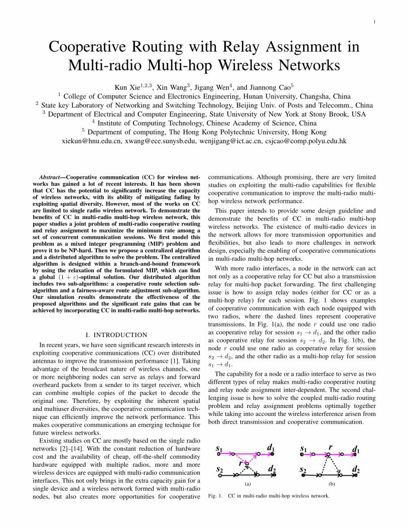
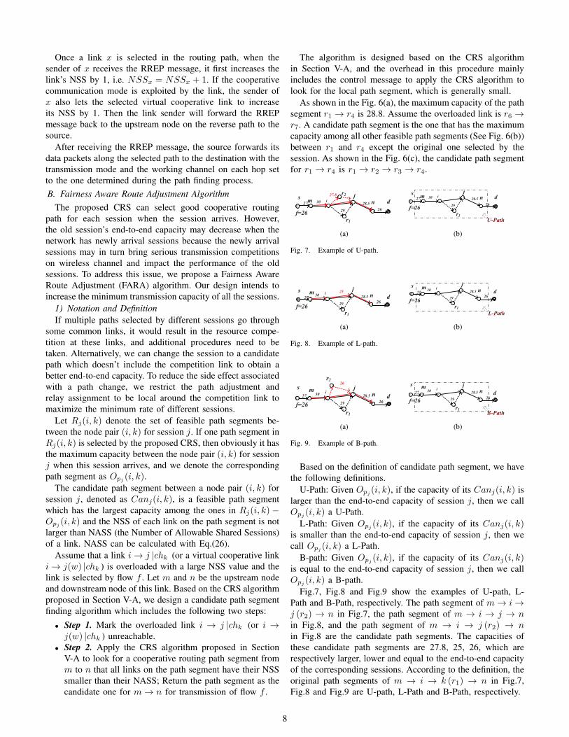
As shown in the Fig. 6(a), the maximum capacity of the pathsegment r1 → r4 is 28.8. Assume the overloaded link is r6 →r7. A candidate path segment is the one that has the maximumcapacity among all other feasible path segments (See Fig. 6(b))between r1 and r4 except the original one selected by thesession. As shown in the Fig. 6(c), the candidate path segmentfor r1 → r4 is r1 → r2 → r3 → r4.
27.8
28.5i
s jr2
r1
f=2629
30 nm d27
26
(a)
28.5i
s j
r1
f=2629
30 nm d27
26
U-Path
(b)
Fig. 7. Example of U-path.
25
28.5i
s j
r1
f=2629
30 nm
d2726
(a)
28.5i
s j
r1
f=2629
30 nm
d2726
L-Path
(b)
Fig. 8. Example of L-path.
26
28.5i
j
r1
f=26 29
30 n
r2
s md27
26
(a)
28.5i
j
r1
f=26 29
30 ns m
d27
26
B-Path
(b)
Fig. 9. Example of B-path.
Based on the definition of candidate path segment, we havethe following definitions.
U-Path: Given Opj (i, k), if the capacity of its Canj(i, k) islarger than the end-to-end capacity of session j, then we callOpj (i, k) a U-Path.
L-Path: Given Opj (i, k), if the capacity of its Canj(i, k)is smaller than the end-to-end capacity of session j, then wecall Opj (i, k) a L-Path.
B-path: Given Opj (i, k), if the capacity of its Canj(i, k)is equal to the end-to-end capacity of session j, then we callOpj (i, k) a B-path.
Fig.7, Fig.8 and Fig.9 show the examples of U-path, L-Path and B-Path, respectively. The path segment of m → i →j (r2) → n in Fig.7, the path segment of m → i → j → nin Fig.8, and the path segment of m → i → j (r2) → nin Fig.8 are the candidate path segments. The capacities ofthese candidate path segments are 27.8, 25, 26, which arerespectively larger, lower and equal to the end-to-end capacityof the corresponding sessions. According to the definition, theoriginal path segments of m → i → k (r1) → n in Fig.7,Fig.8 and Fig.9 are U-path, L-Path and B-Path, respectively.
8

28.8
s
d
r5
r4
r3r2
r1f=27.8 27.8
30 r6 r7
29.1 28.9
(a)
2321
26.8
s d31
27
r1
r2r3
r4
r5
30
27.8
r6 r7
(b)
s d
3127
f=26.8
26.8 r3
r4r5
r1
r2
30
27.8
r6 r7
(c)
Fig. 6. Example of Candidate link .
2) Algorithm designGiven any path segment p ∈ Rj(i, k), the path segment must
be one type of U-Path, L-Path and B-path. Among the NSSpath segments belonging to different sessions, assuming thereare n1 U-paths, n2 L-Path and n3 B-Path, we have NSS =n1 + n2 + n3.
Given a link x that is selected by NSSx sessions, the end-to-end capacity of these sessions are P1, P2, · · · , PNSSx , (theend-to-end capacity is calculated based on all links along thepath except the competition link x), the available capacity ofthis link is C(x) (C(x) calculated with Eq.(15) or Eq.(16)depending on the transmission mode of the link, then therelationship of NASS of this link and the end-to-end pathcapacity of these sessions can be expressed as
C(x)
NASSx≥ min {P1, P2, · · · , PNSSx} , (24)
that isNASSx ≤ C(x)
min {P1, P2, · · · , PNSSx}. (25)
Furthermore, because NASSx is an integer, we have
NASSx =
⌊C(x)
min {P1, P2, · · · , PNSSx}
⌋, (26)
where ⌊∗⌋ is floor function and ⌊y⌋ is the largest integer notlarger than y.
Given a link x, if NSSx > NASSx, we need to adjustthe routing path selection and relay assignment around thecompetition link. As a basic principle of our Fairness AwareRouting Adjustment (FARA) algorithm, in order not to reducethe capacity of the sessions that go through the L-Path, thecompetition link will first switch some or all U-Paths and B-Paths to their candidate path segments. Among the L-Paths,we give resource preference to the ones with lower capacity.We consider two cases in our algorithm:
Case A: 0 ≤ n2 ≤ NASSx. The competition link x keepsall L-Path, as well as NASSx − n2 U-Path or B-Path thesame, and randomly switches NSSx−NASSx path-segmentsamong n1 +n3 (U-Paths and B-Paths) to their candidate pathsegments for the corresponding sessions.
Case B: n2 > NASSx. The competition link x firstswitches all the U-Paths and B-Paths to their candidate pathsegments. Then it sorts the capacity of n2 candidate paths,and switches the top n2 − NASSx ones to go through theircandidate path segments.
One example of Case B is shown in Fig.10. In the example,there are three sessions using link r9 → r10 through three pathsegments, r1 → r9 → r10 → r2, r3 → r9 → r10 → r4, and
r5 → r9 → r10 → r6, as shown in Fig. 10(a). The end-to-end capacities of these three sessions are 25.3, 23.8 and 23,respectively. We assume that NASS = 2 for link r9 → r10.Therefore, we need to switch one path segment among thethree ones to its candidate path segment. Fig. 10(b) shows thethree corresponding candidate path segments, r1 → r2(r7),r3 → r5(r8) → r6 → r4, r5 → r6, with the capacity 24.1,21.5 and 22 respectively. Among all these three sessions, thecapacity of the candidate path segment in session 1 has thehighest value. According to our algorithm, we switch r1 →r9 → r10 → r2 for session 1 to r1 → r2(r7) as shown inFig. 10(c). After the switch, the capacity of the three pathscorresponding to different sessions are 24.1, 23.8 and 23.
Another example of Case A is shown in Fig.11. In thisexample, the end-to-end capacities of the three sessions are25.3, 25 and 24, respectively. Fig. 11(b) shows the threecandidate path segments of the corresponding three sessionswhich do not involve the competition link r9 → r10 ,r1 → r2(r7), r3 → r5(r8) → r6(r9) → r4, r5 → r6(r9),with the capacity 27, 25.5 and 25.6 respectively. Accordingto our algorithm, because all the capacities of candidate pathsegments of the three sessions are larger than the capacity oftheir end-to-end paths, we can randomly switch one path toits candidate path, as shown in Fig.11(c). After the switch, thecapacity of the three sessions remains the same as that beforeswitch.
3) Ripple Effect ReductionIt is worth pointing out that we follow an important principle
to identify the candidate path segment: the candidate pathsegment should not include the links whose NSS is not smallerthan NASS.
The purpose of introducing this rule is to avoid networkinstability as a result of triggering FARA to run in theswitched candidate path segment thus subsequent rounds ofroute adjustments. If any link on the candidate path segmenthas NSS larger than NASS, it may need to restart anotherFARA algorithm after additional sessions are switched tothis path segment. This will lead to instability. Ideally, foreach candidate path segment, we should check its impact onnetwork stability before activating the candidate path segmentto route traffic for a session. Checking stability of network,however, is a time consuming task. Instead, we propose thesimple rule.
We call the result of triggering FARA to run around someoverloaded links on the candidate path as Ripple Effect.We call Ripple Effect link as the one on the candidate pathwhose NSS is not smaller than NASS. To reduce the ripple
9

f2=23.8
r1
d2
f1=25.3
d1
d3f3=23
r2
r3
r4
r5 r6
56
23.8
23
r8s2
s1
s3
r7
25.3 28
2524
2428
r9 r10 24
27 2626
(a)
f2=21.5
r1
d2
f1=24.1
d1
d3f3=22
r2
r3
r4
r5 r6
r8s2
s1
s3
r7
25.3 28
2524
2428
r9 r10
C1'=24.1
C2'=21.5
2222.5
(b)
f2=23.8
r1
d2
f1=24.1
d1
d3f3=23
r2
r3
r4
r5 r6
56
23.8
23
r8s2
s1
s3
r7
25.3 28
2524
2428
r9 r10 24
26
24.1
(c)
Fig. 10. Example of FARA procedure with n2 > NASS.
f2=25
r1
d2
f1=25.3
d3f3=24
r3
r4
r5r6
2826r8s2
s1
s3
r7
25.3
25 29
24
28
r9
d1r2 28
26 58
2828
25.5
r10
r11
(a)
f2=25
r1
d2
f1=25.3
d3f3=24
r3
r4
r5r6
r8s2
s1
s3
r7
25.3
25 29
24
28
r9
d1r2 28
r10
r11
25.6
C3'=25.6
27
C2'=25.5
C1'=27
(b)
f2=25
r1
d2
f1=25.3
d3f3=24
r3
r4
r5r6
2826r8s2
s1
s3
r7
25.3
25 29
24
28
r9
d1r2 28
26 58
28
r10
r11
25.6
(c)
Fig. 11. Example of FARA procedure with 0 ≤ n2 ≤ NASS.
effect, in this paper, we simply avoid selecting candidate pathscontaining ripple effect links. In case there does not exist acandidate path segment without introducing the ripple effect,multiple sessions may share a link, and different sessions canbe coordinated in transmissions using the MAC layer schemesuch as CSMA or TDMA.
s1
s2s3
d1d2
d3
s4d4d5
s5r4
r1r2
r3r5
r7 r6
(a)
s1
s2s3
d1d2
d3
s4d4d5
s5r4
r1r2
r3r5
r7 r6
(b)
Fig. 12. Example of ripple effect discussion.
We illustrate this scenario by an example in Fig. 12. Linkr3 → r5 is shared by three sessions and link r1 → r2(r4) isshared by two sessions. The NASS of link r3 → r5 and linkr1 → r2(r4) are 2. We assume that link r3 → r5 will invokeFARA algorithm and select to change session 1 to go throughlink r1 → r2(r4). As a result of path switching, link r1 →r2(r4) would have three sessions going through it, and thenwould have to invoke another FARA algorithm. This effectmay be propagated along a chain of such neighboring linkswith NSS larger than their NASS. If session 1 does not selectto go through link r1 → r2(r4) for its data transmission, linkr1 → r2(r4) may not have to invoke another FARA algorithm.Therefore, in the above example, link r7 → r6 instead r1 →r2(r4) should be selected for session 1, as shown in Fig. 12(b).
4) Avoidance of Route Adjustment ConflictIf each link independently makes a local route adjustment
decision, multiple route adjustment requests may be receivedsimultaneously by a link, which may lead to a route adjustmentcollision and decision conflict at the link. This will furthermake the link be a Ripple Effect link, and invoke anotherFARA algorithm again.
d2
d3
s2
s1
s3
d1
d6
d5
d7
s6
s5
s7
d4s4
r2 r1
r3 r4
r5 r6
(a)
d2
d3
s2
s1
s3
d1
d6
d5
d7
s6
s5
s7
d4s4
r2 r1
r3 r4
r5 r6
(b)
Fig. 13. Example of route adjustment conflict.
We illustrate route adjustment conflict problem by an ex-ample in Fig. 13. In Fig.13(a), link r2 → r1 and r5 → r6 areall shared by three sessions, but the NASS of these two linksare 2. If link r2 → r1 and r5 → r6 invoke FARA algorithmindependently, link r3 → r4 may be selected in session 3(s3 → d3) and session 5 (s5 → d5) after route adjustment, asshown in Fig.13(b). As a result of path switching, link r3 → r4would have three sessions going through, and then would haveto invoke another FARA algorithm.
To mitigate this problem, we introduce a random delaybefore a link w invokes FARA algorithm when the link detects
10
that itself is shared by multiple sessions with the NSSw largerthan its NASSw, and the timer can be set as follows:
Timerw =1
NSSw −NASSw+ random (0, g) , (27)
where the random number within (0, g) is added to reducecollisions and decision conflicts from multiple requests ofroute adjustment. The link with a higher load, i.e., a largergap of NSSw − NASSw, has a lower average timer valuethus an earlier chance of adjusting its local route.C. Convergence Analysis
In [39], the author gives the formal analysis of convergenceof AODV protocol. Our cooperative routing algorithm (CRS)is designed based on AODV, and it is clear that the process ofour CRS converges. Therefore, we only need to show that theprocess of route adjustment can converge and reach a stablestate.
Theorem 2: If every overloaded link invokes FARA algo-rithm to adjust its local path segment following the procedurein Section V-B, within a finite number of path segmentswitches, the network will reach a stable state where all linksstop the route adjustment.
Proof: Consider that a link i invokes FARA algorithmwhen detecting that it is overloaded (NSSi > NASSi)and begins to switch some of its sessions on link i to theircandidate path segments at time t, and completes the pathsegment switches at time t′ ( t′ > t). According to theprocedure in Section V-B, NSSi − NASSi sessions shouldswitch their transmissions to the candidate path segments. LetPi denote the link set on the candidate path segments.
In Section V-B4, we have the route adjustment timer setfollowing the Eq.(27). This makes the chance for any otherlink j to trigger its local route adjustment simultaneously withlink i very small. Therefore, at the time t′, only links in Pi
would be the new links (besides the links originally involvedin sessions) that may trigger a route adjustment.
According to the principle in candidate-path-segment se-lection in Section V-B3, the candidate path segment shouldnot include a link whose NSS is not smaller than its NASS.Therefore, these route switches will not make the links in Pi
trigger another route adjustment.Therefore, although our route adjustment depends only
on the information available within a local domain and isdesigned to be distributed, the route adjustment process canself-stabilize and help the network to reach the stable state.
VI. CENTRALIZED ALGORITHM
For performance reference, we further propose a central-ized algorithm. As one of the approaches to solving IntegerProgramming (IP) problems [40], branch-and-bound methodfinds the optimal solution to an IP by efficiently enumeratingthe points in the feasible region. Based on branch-and-boundframework, we propose a Centralized joint Flow Routingand Relay Assignment algorithm (CFRRA) to solve the MIPproblem in (21), as shown in algorithm 3.
The basic idea of CFRRA is as follows. By using therelaxation in step 3, we can efficiently compute a global upper
bound, UB, for problem in (21). This relaxation solutioneither yields a feasible solution to the problem or, if notfeasible, it can be used as a starting point for a local search tofind a feasible solution. This feasible solution then serves toprovide a global lower bound, LB, and an incumbent solutionto the problem. The branch-and-bound process proceeds bytightening LB and UB through a series of partitions over theproblem domain, and terminates when UB ≤ (1 + ε)LB issatisfied, where ε > 0 is some desired approximation error.
Algorithm 3 Centralized Joint Flow Routing and Relay As-signment Algorithm (CFRRA)
1: Let the optimal solution φ∗ = ϕ and the initial lower boundLB = 0.
2: Let the initial problem list contain only the original problem in(21), denoted by P1.
3: Construct the relaxation for P1 by relaxing the constraintxwkj:uv, y
kj:uv ∈ {0, 1} to xwk
j:uv, ykj:uv ∈ [0, 1], and solve it.
Denote the solution to this relaxation as φ1 and its objectivevalue as the upper bound UB1.
4: Select a problem Pz that has the highest upper bound (designatedas UB) among all the problems in the problem list.
5: Find, if necessary, a feasible solution φz via a local searchalgorithm for Pz . Denote the objective value of φz by LBz.
6: If LBz > LB, then let φ∗ = φz and LB = LBz. If UB ≤(1+ε)LB, then stop with the (1+ε)-optimal solution φ∗; else,remove all problems Pz′ having UBz′ ≤(1 + ε)LB from theproblem list.
7: Select a binary xwkj:uv or yk
j:uv and branch on the dichotomy ofits values being 0 or 1.
8: Remove the selected problem Pz from the problem list, constructtwo new problems Pz1 and Pz2 based on the foregoing branchingstep.
9: Compute two new upper bounds UBz1 and UBz2 by solvingthe programming relaxations of Pz1 and Pz2, respectively.
10: If UBz1 > (1 + ε)LB then add Problem Pz1 to the problemlist. If UBz2 > (1+ε)LB then add Problem Pz2 to the problemlist.
11: If the problem list is empty, stop with the (1 + ε)− optimalsolution φ∗. Otherwise, go to Step 4.
VII. SIMULATION RESULTS
We present some simulation results to demonstrate therate gain by jointly applying interference-aware cooperativerouting and relay assignment in multi-flow multi-radio multi-channel wireless networks. In this section, we first describethe simulation setup, and then present the simulation results.A. Simulation Setup
We evaluate the performance of our proposed algorithmsthrough extensive simulations using MATLAB. There are 12orthogonal channels in the network in total, and the defaultnumber of sessions in the network is set to 4. Following theparameter setting in [14], we set the bandwidth W of eachchannel to 22 MHz, the maximum transmission power at everynode to 1 W. The channel gain contains the path loss andthe Rayleigh fading coefficient. White Gaussian noise withthe variance 10−10 W is added to include environment noiseimpact.
In the simulations, 60 nodes are generated randomly in a1000m × 1000m area. Each node is equipped with 3 radios,
11

and the maximum communication range is set to 250 meters.The interference range is set to twice the communication rangeand will change with the communication range varies.
There is no existing work studying cooperative communi-cations with multi-flow routing in multi-radio multi-channelnetworks. We implement eight routing algorithms in differentnetwork scenarios for performance comparisons, which areintroduced as follows.
1) For performance comparison, we implement our pro-posed centralized algorithm CFRRA in Algorithm 3 ina multi-radio multi-channel cooperative networks withε = 0.1 in the algorithm, denoted as CFRRA-MRMC-CC.
2) We implement our proposed multi-flow multi-radiomulti-channel cooperative routing algorithm DFRRA inSection V which includes two sub-algorithms: the co-operative routing sub-algorithm in Section V-A and thefairness-aware route adjustment in Section V-B, denotedas DFRRA-MRMC-CC.
3) The CRS algorithm in Section V-A is applied to findthe maximum end-to-end cooperative path which has themaximum capacity for each new session. We implementthe CRS scheme in a multi-radio multi-channel cooper-ative wireless network, denoted as CSC-MRMC-CC.
4) Different from the third scheme, we implement the CRSin a single-radio single-channel cooperative wirelessnetwork where each node is assigned with the samechannel, denoted as CSC-SRSC-CC.
5) Different from the third scheme, we implement CRS in asingle-radio multi-channel cooperative wireless networkwhere each node is assigned with a channel randomlyselected from the set of orthogonal channels, denoted asCSC-SRMC-CC.
6) We implement a non-cooperative routing algorithm inwhich the Bellman-Ford path algorithm is applied tosearch for the maximum end-to-end capacity path foreach new session in multi-radio multi-channel wirelessnetwork, denoted as Bellman-MRMC-NC.
7) Different from the sixth scheme, we implement thenon-cooperative routing algorithm in single-radio single-channel wireless network, denoted as Bellman-SRSC-NC.
8) Different from the sixth scheme, we implement thenon-cooperative routing algorithm in single-radio multi-channel wireless network, denoted as Bellman-SRMC-NC.
Note that the last three algorithms Bellman-MRMC-NC,Bellman-SRSC-NC, and Bellman-SRMC-NC consider a non-cooperative wireless network which only consists of flowrouting for each session.
In the last six algorithms, if multiple sessions select thesame link, TDMA type scheduling can be applied at the MAClayer to allocate time slots to different active sessions basedon certain fairness rule.
We evaluate the performance of our distributed algorithmDFRRA-MR-CC under different node density, number of ses-sions, number of radio interfaces on a node, and the communi-cation ranges. Unless otherwise specified, the default number
of nodes in the network is 60, the number of sessions is 4, eachnode is equipped with 3 radios, and the communication rangeis 250 meters. A simulation result is obtained by averagingover 20 runs of simulations.B. Simulation Result
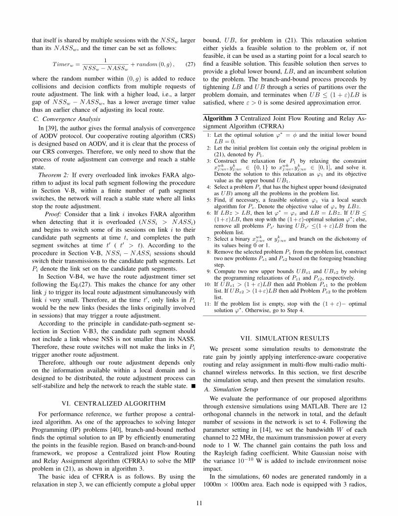
1) Impact of node densityIn Fig.14, the aggregate rate and minimum rate (in term of
kbps) under all routing algorithms increase as the number ofnodes increases, as there are more candidate relay nodes.
Compared with the aggregate rate of single-radio net-work Bellman-SRSC-NC, the rate of the multi-radio net-work DFRRA-MRMC-CC is about 6-8 times. The intro-duction of multi-radio nodes with multi-channel significantlyincreases the flexibility in relay selection and decreases thewireless interference thus achieving higher performance gain.Compared to CRS-MRMC-CC, CRS-SRSC-CC, CRS-SRMC-CC, Bellman-MRMC-NC, Bellman-SRSC-NC, and Bellman-SRMC-NC, we find that our two multi-radio multi-channel co-operative routing algorithms, the centralized CFRRA-MRMC-CC and the distributed DFRRA-MRMC-CC, have the largestaggregate rate and minimum rate. Compared to Bellman-MRMC-NC, DFRRA-MRMC-CC can increase up to 78% theaggregate transmission rate. This demonstrates the significantperformance gain achieved by incorporating CC in multi-radiomulti-channel multi-hop wireless networks.
In a multi-channel wireless network, two nodes can com-municate only if they are assigned a common channel. For asingle radio wireless network, a node can be assigned at mostone channel. If the channel assigned to the node is randomlyselected, nodes in the single-radio multi-channel network hasa limited number of neighbors. Thus there are limited numberof links in the network, and the curves of CRS-SRMC-CC andBellman-SRMC-NC are close to x axis as shown in Fig.14.
Moreover, compared to CRS-MRMC-CC, our DFRRA-MRMC-CC can obtain up to 40% and 41% higher aggregaterate and minimum rate, respectively. This indicates that theFairness-Aware Route Adjustment algorithm (FARA) pro-posed in Section V-B and included in DFRRA-MRMC-CCcan effectively resolve the resource competition among dif-ferent sessions and ensure higher minimum throughput acrosssessions. CRS-MRMC-CC simply coordinates transmissionsthrough TDMA when multiple sessions share links, whichwill compromise the performance. When the number of relaynodes is small, there may be more relay competitions amongdifferent sessions. Our FARA algorithm can more effectivelyadapt the relay selections on competitive routing segments toincrease the aggregate rate.
2) Impact of the number of sessionsIn Fig 15, as the number of sessions increases, the aggregate
rate increases, while the minimum rate decreases. This isas expected. The larger number of sessions bring highercompetitions on the relay nodes and channel resources in thenetwork, which results in larger interference thus the reductionof the minimum throughput.
The two multi-radio cooperative routing algorithms,CFRRA-MRMC-CC and DFRRA-MRMC-CC, have muchbetter performance compared to other routing algorithms.Compared with CRS-MRMC-CC, our DFRRA-MRMC-CC
12

40 60 80 100 120 140020406080100120140160180200220
Agg
rega
te R
ate
No.Node
CFRRA-MRMC-CC CRS-SRMC-CC DFRRA-MRMC-CC Bellman-MRMC-NC CRS-MRMC-CC Bellman-SRSC-NC CRS-SRSC-CC Bellman-SRMC-NC
(a) aggregate rate
40 60 80 100 120 140
0
5
10
15
20
25
30
Min
imum
Rat
e
No.Node
CFRRA-MRMC-CC CRS-SRMC-CC DFRRA-MRMC-CC Bellman-MRMC-NC CRS-MRMC-CC Bellman-SRSC-NC CRS-SRSC-CC Bellman-SRMC-NC
(b) minimum rate
Fig. 14. Impact of node density.
2 3 4 5 6 7 8020406080100120140160180200220240
Agg
rega
te R
ate
No.Session
CFRRA-MRMC-CC CRS-SRMC-CC DFRRA-MRMC-CC Bellman-MRMC-NC CRS-MRMC-CC Bellman-SRSC-NC CRS-SRSC-CC Bellman-SRMC-NC
(a) aggregate rate
2 3 4 5 6 7 8024681012141618202224262830
Min
imum
Rat
e
No.Session
CFRRA-MRMC-CC CRS-SRMC-CC DFRRA-MRMC-CC Bellman-MRMC-NC CRS-MRMC-CC Bellman-SRSC-NC CRS-SRSC-CC Bellman-SRMC-NC
(b) minimum rate
Fig. 15. Impact of number of sessions.
achieves the same performance when the number of sessions is2, and achieves higher aggregate rate and minimum rate whenthe number of session is larger than 2. When the number ofsessions is small, the relay nodes and channels are sufficient toserve all sessions. In Fig.15(b), compared with CRS-MRMC-CC, as the number of sessions increases, the gain of ourDFRRA-MRMC-CC is seen to increase initially and thenreduce. Our FARA algorithm can effectively mitigate linkcompetition initially, but the performance of DFRRA-MRMC-CC suffers when the number of sessions is very large and thereare very few candidate relays to exploit.
3) Impact of the number of radiosWhen varying the number of radios from 2 to 10 in
Fig. 16, the aggregate rate and minimum rate achieved byCFRRA-MRMC-CC, DFRRA-MRMC-CC, CRS-MRMC-CC,and Bellman-MRMC-NC increase, as there are more relayand transmission channel options. As CRS-SRSC-CC andBellman-SRSC-NC are single-radio routing algorithms, thenumber of radios don’t have impact on their performance as inFig. 16. Similar to the reason of Fig 15, due to limited linksin single-radio multi-channel networks, the curves of CRS-SRMC-CC and Bellman-SRMC-NC are close to x axis.
The performance of DFRRA-MRMC-CC outperforms CRS-MRMC-CC when there are competitions in relay and linkaccess, which demonstrates that our DFRRA-MRMC-CC canmake use of relay and channel resource more efficiently.
Compared to Bellman-MRMC-NC, our DFRRA-MRMC-CC can obtain up to 30% and 37% higher aggregate rate andminimum rate respectively, which demonstrates that cooper-ative transmissions outperform direct transmissions in multi-radio multi-channel multi-hop wireless networks.
4) Impact of the communication rangeIn order to observe the effect brought by the transmission
distance, we vary the communication range from 100 to 400meters in the network. As shown in Fig.17, when the commu-
2 4 6 8 10020406080100120140160180200220240
Agg
rega
te R
ate
No.Radio Per Node
CFRRA-MRMC-CC CRS-SRMC-CC DFRRA-MRMC-CC Bellman-MRMC-NC CRS-MRMC-CC Bellman-SRSC-NC CRS-SRSC-CC Bellman-SRMC-NC
(a) aggregate rate
2 4 6 8 10-505
1015202530354045
Min
imum
Rat
e
No.Radio Per Node
CFRRA-MRMC-CC CRS-SRMC-CC DFRRA-MRMC-CC Bellman-MRMC-NC CRS-MRMC-CC Bellman-SRSC-NC CRS-SRSC-CC Bellman-SRMC-NC
(b) minimum rate
Fig. 16. Impact of number of radios.
100 150 200 250 300 350 400
0
20
40
60
80100
120
140
160
180
Agg
rega
te R
ate
Communication Range
CFRRA-MRMC-CC CRS-SRMC-CC DFRRA-MRMC-CC Bellman-MRMC-NC CRS-MRMC-CC Bellman-SRSC-NC CRS-SRSC-CC Bellman-SRMC-NC
(a) aggregate rate
100 150 200 250 300 350 400
0
5
10
15
20
25
30
35
Min
imum
Rat
e
Communication Range
CFRRA-MRMC-CC CRS-SRMC-CC DFRRA-MRMC-CC Bellman-MRMC-NC CRS-MRMC-CC Bellman-SRSC-NC CRS-SRSC-CC Bellman-SRMC-NC
(b) minimum rate
Fig. 17. Impact of the communication range.
nication range is very small, the aggregate rate and minimumrate for all the routing schemes are zero because nodes havelimited number of neighbors and there are limited links in thewireless networks. The aggregate rate and minimum rate forall the routing schemes increase initially. However, with thefurther increase of the communication range, the throughputreduces until the communication range reaches a certain value,then maintains a stable throughput.
On the one hand, the increase of the communication rangeleads to higher number of links thus more options to selectrelays and next-hop nodes. The initial increase of communi-cation range also helps to increase the network connectivityand find a better transmission path. On the other hand, alarger communication range also creates higher interferenceand hence reduces the routing performance. Therefore, it isnot helpful to use too high transmission power to increase thecommunication range. Similar to the results in Fig.14, Fig.15,and Fig.16, our scheme CFRRA-MRMC-CC and DFRRA-MRMC-CC show better performance compared with otherschemes in Fig.17.
In summary, all the simulation results demonstrate that, ourdistributed algorithm DFRRA-MRMC-CC is seen to achievethe performance close to the bound provided by the central-ized algorithm CFRRA-MRMC-CC while running much moreefficiently.
VIII. CONCLUSION
This paper studies a joint problem of cooperative routingand relay assignment in multi-hop and multi-radio networksto maximize the minimum rate among a set of concurrentcommunication sessions. We first model this problem as amixed integer programming (MIP) problem and prove it tobe NP-hard. Then we propose a centralized algorithm and adistributed algorithm to solve the problem. The centralized
13

algorithm can guarantee the finding of a global (1+ε)-optimalsolution. The distributed algorithm can be applied to find anefficient cooperative route with polynomial complexity. Wehave done extensive simulations to evaluate the performance,and our results demonstrate the effectiveness of the proposedalgorithms and the significant rate gains that can be achievedby incorporating CC in multi-radio multi-hop networks. Al-though we use AF as the CC mode in this paper, it is worthpointing out that our algorithms do not depend on specific CCmode to function.
ACKNOWLEDGMENT
The work is supported by the open Foundation of State keyLaboratory of Networking and Switching Technology (BeijingUniversity of Posts and Telecommunications) under GrantNo. SKLNST-2013-1-04, the Prospective Research Project onFuture Networks (Jiangsu Future Networks Innovation Insti-tute) under Grant No. BY2013095-4-06, the National NaturalScience Foundation of China under Grant Nos. 61173167, and61472131, U.S. National Science Foundation under Grant Nos.ECCS-1408247 and CNS 1247924.
REFERENCES
[1] Q. Zhang, J. Jia, and J. Zhang, “Cooperative relay to improve diversityin cognitive radio networks,” IEEE Communications Magazine, vol. 47,no. 2, pp. 111–117, 2009.
[2] J. Cai, X. Shen, J. W. Mark, and A. S. Alfa, “Semi-distributed userrelaying algorithm for amplify-and-forward wireless relay networks,”IEEE Transaction on Wireless Communication, vol. 7, no. 4, pp. 1348–1357, 2008.
[3] B. Wang, Z. Han, and K. Liu, “Distributed relay selection and powercontrol for multiuser cooperative communication networks using buy-er/seller game,” in INFOCOM 2007.
[4] Y. Shi, S. Sharma, Y. T. Hou, and S. Kompella, “Optimal relayassignment for cooperative communications,” in MobiHoc 2008.
[5] P. Zhang, Z. Xu, F. Wang, X. Xie, and L. Tu, “A relay assignmentalgorithm with interference mitigation for cooperative communication,”in WCNC 2009.
[6] Z. Yang, Q. Zhang, and Z. Niu, “Throughput improvement by joint relayselection and link scheduling in relay-assisted cellular networks,” IEEETransactions on Vehicular Technology, vol. 61, no. 6, pp. 2824–2835,2012.
[7] D. Yang, X. Fang, and G. Xue, “Hera: An optimal relay assignmentscheme for cooperative networks,” IEEE Journal on Selected Areas inCommunications, vol. 30, no. 2, pp. 245 –253, 2012.
[8] A. Khandani, J. Abounadi, E. Modiano, and L. Zheng, “Cooperativerouting in static wireless networks,” IEEE Transactions on Communica-tions, vol. 55, no. 11, pp. 2185 –2192, 2007.
[9] E. Yeh and R. Berry, “Throughput optimal control of cooperative relaynetworks,” IEEE Transactions on Information Theory, vol. 53, no. 10,pp. 3827 –3833, 2007.
[10] G. Jakllari, S. V. Krishnamurthy, M. Faloutsos, P. V. Krishnamurthy, andO. Ercetin, “A cross-layer framework for exploiting virtual miso linksin mobile ad hoc networks,” IEEE Transactions on Mobile Computing,vol. 6, no. 6, pp. 579 –594, 2007.
[11] S. Lakshmanan and R. Sivakumar, “Diversity routing for multi-hopwireless networks with cooperative transmissions,” in SECON 2009.
[12] M. Elhawary and Z. Haas, “Energy-efficient protocol for cooperativenetworks,” IEEE/ACM Transactions on Networking, vol. 19, no. 2,pp. 561 –574, 2011.
[13] A. Ibrahim, Z. Han, and K. Liu, “Distributed energy-efficient cooperativerouting in wireless networks,” IEEE Transactions on Wireless Commu-nications, vol. 7, no. 10, pp. 3930 –3941, 2008.
[14] S. Sharma, Y. Shi, Y. Hou, H. Sherali, and S. Kompella, “Cooperativecommunications in multi-hop wireless networks: Joint flow routing andrelay node assignment,” in INFOCOM 2010.
[15] D. Gunduz and E. Erkip, “Opportunistic cooperation by dynamicresource allocation,” IEEE Transactions on Wireless Communications,vol. 6, no. 4, pp. 1446 –1454, 2007.
[16] O. Gurewitz, A. de Baynast, and E. Knightly, “Cooperative strategiesand achievable rate for tree networks with optimal spatial reuse,” IEEETransactions on Information Theory, vol. 53, no. 10, pp. 3596 –3614,2007.
[17] T. Hunter and A. Nosratinia, “Diversity through coded cooperation,”IEEE Transactions on Wireless Communications, vol. 5, no. 2, pp. 283– 289, 2006.
[18] S. Savazzi and U. Spagnolini, “Energy aware power allocation strate-gies for multihop-cooperative transmission schemes,” IEEE Journal onSelected Areas in Communications, vol. 25, no. 2, pp. 318 –327, 2007.
[19] A. Sendonaris, E. Erkip, and B. Aazhang, “User cooperation diversity.part i. system description,” IEEE Transactions on Communications,vol. 51, no. 11, pp. 1927 – 1938, 2003.
[20] H. Xu, L. Huang, C. Qiao, Y. Zhang, and Q. Sun, “Bandwidth-poweraware cooperative multipath routing for wireless multimedia sensornetworks,” IEEE Transactions on Wireless Communications, vol. 11,no. 4, pp. 1532 –1543, 2012.
[21] X. Li and J. Wu, “Channel on demand: Optimal capacity for cooperativemulti-channel multi-interface wireless mesh networks,” in MASS 2010.
[22] F. Yang, M. Huang, M. Zhao, S. Zhang, and W. Zhou, “Cooperativestrategies for wireless relay networks with cochannel interference overtime-correlated fading channels,” IEEE Transactions on Vehicular Tech-nology, vol. 62, no. 7, pp. 3392–3408, 2013.
[23] Z. Guan, T. Melodia, D. Yuan, and D. A. Pados, “Distributed spectrummanagement and relay selection in interference-limited cooperative wire-less networks,” in Proceedings of the 17th ACM annual internationalconference on Mobile computing and networking, pp. 229–240, 2011.
[24] J. Zhang and Q. Zhang, “Cooperative routing in multi-source multi-destination multi-hop wireless networks,” in Proceedings IEEE INFO-COM, pp. 2369–2377, 2008.
[25] P. Li, S. Guo, and J. Hu, “Energy-efficient cooperative communicationsfor multimedia applications in multi-channel wireless networks,” IEEETransactions on Computers, 2014, DOI 10.1109/TC.2014.2345397.
[26] M. Alicherry, R. Bhatia, and L. E. Li, “Joint channel assignmentand routing for throughput optimization in multi-radio wireless meshnetworks,” in Proceedings of the 11th annual international conferenceon Mobile computing and networking, MobiCom ’05, (New York, NY,USA), pp. 58–72, ACM, 2005.
[27] H. Li, Y. Cheng, C. Zhou, and P. Wan, “Multi-dimensional conflict graphbased computing for optimal capacity in mr-mc wireless networks,” inDistributed Computing Systems (ICDCS), 2010 IEEE 30th InternationalConference on, pp. 774–783, June 2010.
[28] H. Li, Y. Cheng, C. Zhou, and W. Zhuang, “Routing metrics forminimizing end-to-end delay in multiradio multichannel wireless net-works,” Parallel and Distributed Systems, IEEE Transactions on, vol. 24,pp. 2293–2303, Nov 2013.
[29] P.-J. Wan, Z. Wang, L. Wang, Z. Wan, and S. Ji, “From least interference-cost paths to maximum (concurrent) multiflow in MC-MR wirelessnetworks,” in INFOCOM, 2014 Proceedings IEEE, pp. 334–342, April2014.
[30] J. Zhu, X. Wang, and D. Xu, “A unified mac and routing frameworkfor multichannel multi-interface ad hoc networks,” IEEE Transactionson Vehicular Technology, vol. 59, pp. 4589–4601, Nov 2010.
[31] S. Chu, X. Wang, and Y. Yang, “Adaptive scheduling in mimo-basedheterogeneous ad hoc networks,” IEEE Transactions on Mobile Com-puting, vol. 13, pp. 964–978, May 2014.
[32] S. Chu, X. Wang, and Y. Yang, “Exploiting cooperative relay forhigh performance communications in mimo ad hoc networks,” IEEETransactions on Computers, vol. 62, pp. 716–729, April 2013.
[33] S. Chu, X. Wang, and M. Li, “Enforcing high-performance operation ofmulti-hop wireless networks with MIMO relays,” in IEEE InternationalConference on Distributed Computing Systems (ICDCS), (Macau), 2012.
[34] S. Chu and X. Wang, “Opportunistic and cooperative spatial multiplex-ing in mimo ad hoc networks,” IEEE/ACM Transactions on Networking,vol. 18, pp. 1610–1623, Oct 2010.
[35] Y. Zhao, R. Adve, and L. Teng Joon, “Improving amplify-and-forwardrelay networks: Optimal power allocation versus selection,” in ISIT 2006.
[36] F. Li, K. Wu, and A. Lippman, “Energy-efficient cooperative routing inmulti-hop wireless ad hoc networks,” in IPCCC 2006.
[37] Y. Zhu and H. Zheng, “Understanding the impact of interference oncollaborative relays,” IEEE Transactions on Mobile Computing, vol. 7,no. 6, pp. 724 –736, 2008.
[38] P. Nilsson and M. Pioro, “Unsplittable max-min demand allocation-a routing problem,” in HET-NETs’ 05 Third International workingconference, 2005.
[39] D. Obradovic, Formal analysis of convergence of routing protocols. PhDthesis, university of pennsylvania, 2000.
14

[40] W. L. A. Pochet, Yves, Production Planning by Mixed Integer Program-ming. 2006.
Kun Xie received B.S. degrees in communicationengineering, M.S., PhD degrees in computer appli-cation from Hunan University, Changsha, China, in2001, 2004, and 2007 respectively. She worked as apostdoctoral fellow in the department of computingin Hong Kong Polytechnic University from 2007.12to 2010.2. She worked as a visiting researcher in thedepartment of electrical and computer engineeringin state university of New York at Stony Brookfrom 2012.9 to 2013.9. She is currently an associateprofessor in Hunan University. Her research interests
include wireless network and mobile computing, network management andcontrol, cloud computing and mobile cloud, and big data. She has publishedabout 60 papers and applied 20 patents in her research areas.
Xin Wang (M’1 / ACM’4) received the B.S. andM.S. degrees in telecommunications engineering andwireless communications engineering respectivelyfrom Beijing University of Posts and Telecommu-nications, Beijing, China, and the Ph.D. degree inelectrical and computer engineering from ColumbiaUniversity, New York, NY. She is currently anAssociate Professor in the Department of Electricaland Computer Engineering of the State Universityof New York at Stony Brook, Stony Brook, NY.Before joining Stony Brook, she was a Member of
Technical Staff in the area of mobile and wireless networking at Bell LabsResearch, Lucent Technologies, New Jersey, and an Assistant Professor in theDepartment of Computer Science and Engineering of the State University ofNew York at Buffalo, Buffalo, NY. Her research interests include algorithmand protocol design in wireless networks and communications, mobile anddistributed computing, as well as networked sensing and detection. Shehas served in executive committee and technical committee of numerousconferences and funding review panels, and is the referee for many technicaljournals. Dr. Wang achieved the NSF career award in 2005, and ONRchallenge award in 2010.
Jigang Wen received PhD degrees in computerapplication from Hunan University, China, in 2011.He worked as a research assistant in the departmentof computing in Hong Kong Polytechnic Universityfrom 2008 to 2010. His research interests includewireless network and mobile computing, high speednetwork measurement and management.
Jiannong Cao (M’93-SM’05-FM’14) Dr. Cao iscurrently a chair professor and head of the De-partment of Computing at Hong Kong PolytechnicUniversity, Hung Hom, Hong Kong. He is alsothe director of the Internet and Mobile ComputingLab in the department. Dr. Cao’s research interestsinclude parallel and distributed computing, computernetworks, mobile and pervasive computing, faulttolerance, and middleware. He has co-authored abook in Mobile Computing, co-edited 9 books, andpublished over 300 papers in major international
journals and conference proceedings. He has directed and participated innumerous research and development projects and, as a principal investigator,obtained over HK$25 million grants from government funding agencies andindustries. Dr. Cao has won numerous prizes and awards, and is very activein professional activities locally and internationally. He is a senior memberof China Computer Federation, a senior member of IEEE, and a member ofACM. He was the Coordinator in Asia and now the Chair of the TechnicalCommittee on Distributed Computing of IEEE Computer Society. Dr. Cao hasserved as an associate editor and a member of the editorial boards of manyinternational journals, including IEEE Transactions on Parallel and DistributedSystems, IEEE Transactions on Computers, IEEE Networks, Pervasive andMobile Computing Peer-to-Peer Networking and Applications, and Journal ofComputer Science and Technology. He has also served as a chair and memberof organizing / program committees for many international conferences,including PERCOM, INFOCOM, ICDCS, IPDPS, ICPP, RTSS, DSN, ICNP,SRDS, MASS, PRDC, ICC, GLOBECOM, and WCNC. Dr. Cao received theBSc degree in computer science from Nanjing University, Nanjing, China, andthe MSc and the Ph.D degrees in computer science from Washington StateUniversity, Pullman, WA, USA.
15