Cooling Water Options for the New Generation of Nuclear ... · and hence a 1,000 megawatt electric...
214
Cooling Water Options for the New Generation of Nuclear Power Stations in the UK SC070015/SR3
Transcript of Cooling Water Options for the New Generation of Nuclear ... · and hence a 1,000 megawatt electric...

Cooling Water Options for the New Generation of Nuclear Power Stations in the UK SC070015/SR3

Cooling Water Options for the New Generation of Nuclear Power Stations in the UK ii
The Environment Agency is the leading public body protecting and improving the environment in England and Wales.
It’s our job to make sure that air, land and water are looked after by everyone in today’s society, so that tomorrow’s generations inherit a cleaner, healthier world.
Our work includes tackling flooding and pollution incidents, reducing industry’s impacts on the environment, cleaning up rivers, coastal waters and contaminated land, and improving wildlife habitats.
This report is the result of research commissioned and funded by the Environment Agency.
Author(s): Turnpenny, A.W.H., Coughlan, J., Ng, B., Crews, P., Bamber, R.N., Rowles, P. Dissemination Status: Released to all regions Publicly available Keywords: Nuclear, cooling water, entrainment, impingement, thermal Research Contractor: Jacobs Engineering Ltd Kenneth Dibben House Enterprise Road Chilworth Science Park Southampton SO16 7NS UK Tel.: +44(0)2380 893 513 Fax: +44(0)2380 243 274 Environment Agency’s Project Manager: Claire Cailes, Richard Fairclough House, Knutsford Road, Warrington, UK. Science Project Number: SC070015/SR3 Product Code: SCHO0610BSOT-E-P
Published by: Environment Agency, Rio House, Waterside Drive, Aztec West, Almondsbury, Bristol, BS32 4UD Tel: 01454 624400 Fax: 01454 624409 www.environment-agency.gov.uk ISBN: 978-1-84911-192-8 © Environment Agency June 2010 All rights reserved. This document may be reproduced with prior permission of the Environment Agency. The views and statements expressed in this report are those of the author alone. The views or statements expressed in this publication do not necessarily represent the views of the Environment Agency and the Environment Agency cannot accept any responsibility for such views or statements. This report is printed on Cyclus Print, a 100% recycled stock, which is 100% post consumer waste and is totally chlorine free. Water used is treated and in most cases returned to source in better condition than removed. Further copies of this report are available from our publications catalogue: http://publications.environment-agency.gov.uk or our National Customer Contact Centre: T: 08708 506506 E: [email protected].

Cooling Water Options for the New Generation of Nuclear Power Stations in the UK iii
Evidence at the Environment Agency Evidence underpins the work of the Environment Agency. It provides an up-to-date understanding of the world about us, helps us to develop tools and techniques to monitor and manage our environment as efficiently and effectively as possible. It also helps us to understand how the environment is changing and to identify what the future pressures may be.
The work of the Environment Agency’s Evidence Directorate is a key ingredient in the partnership between research, policy and operations that enables the Environment Agency to protect and restore our environment.
The Research & Innovation programme focuses on four main areas of activity:
• Setting the agenda, by informing our evidence-based policies, advisory and regulatory roles;
• Maintaining scientific credibility, by ensuring that our programmes and projects are fit for purpose and executed according to international standards;
• Carrying out research, either by contracting it out to research organisations and consultancies or by doing it ourselves;
• Delivering information, advice, tools and techniques, by making appropriate products available to our policy and operations staff.
Miranda Kavanagh
Director of Evidence

Cooling Water Options for the New Generation of Nuclear Power Stations in the UK iv
Executive summary The consideration of new nuclear power stations is split into two phases. The first phase addresses generic design matters (namely, acceptability of candidate nuclear power station designs) and the second deals with site-specific applications for permits under the Environmental Permitting (England and Wales) Regulations 2010. The Environment Agency, Health and Safety Executive's Nuclear Installations Inspectorate and the Office for Civil Nuclear Security are currently assessing candidate designs of new nuclear power stations. The Environment Agency is exploring the environmental effects of candidate designs based on a generic site description. A statement about the acceptability of that design for a generic site in England and Wales will be provided. Cooling water is required to remove “waste heat” from power stations regardless of whether the stations are nuclear or conventional. A nuclear power station has a typical thermal efficiency of 25-33% (compared to around 40% for a modern coal-fired station) and hence a 1,000 megawatt electric (MWe) nuclear station would typically generate up to 2,000 megawatts of low-grade waste heat. The reasons for this apparent wastage are explained. The report also explores cooling water options for new reactors and evaluates their potential environmental impacts in terms of effects on biota, and thermal, chemical and radionuclide pollution. The findings are focused on, but not confined to, nuclear plants and will have general applicability to other large (above 1,000 MWe) thermal power station projects.
This report is based on publicly available information and publications and the experience of the authors. It provides an overview of power station cooling water systems in use in the UK and abroad. Details of cooling water options for new nuclear power stations in the UK are given. Cooling water system design (direct and indirect cooling water systems, intake and outfall designs), how the design affects the performance of the cooling option and issues such as temperature differentials between water intake and discharge are discussed. An overview of environmental issues associated with cooling water systems of nuclear and other large power stations is presented. Issues arising from water abstraction and discharges are discussed. These include fish and invertebrate intake and impingement on filter screens, effects of passage of planktonic and small life-stages through the cooling system, thermal, chemical, radionuclide pollution, and effects of cooling tower emissions to air. The report also discusses different mitigation measures (such as intake location, intake screen designs to minimise impacts of entrapment, entrainment and impingement, plume abatement techniques to minimise effects of plume formation). Implications of combining conventional liquid discharges within the cooling water discharge are also considered. Environmental issues with specific cooling water options are identified and explained. The report evaluates cooling water options in terms of environmental concerns (including water demand and energy efficiency) and assesses the best options for use in different types of water environments (coastal, estuarine and fresh waters). Effects of climate change on the choice of cooling water options are also briefly considered. It is likely that new UK nuclear stations will be built on coasts or estuaries. A key question at the outset of the study was whether direct cooling (also known as “once-through”) can still be considered Best Available Technology (BAT) for large coastal and estuarine power stations, as set out in the European Commission’s BAT reference

Cooling Water Options for the New Generation of Nuclear Power Stations in the UK v
document on industrial cooling systems (BREF-Cooling, 2001). While this has recently been challenged in relation to a proposed 2,000 MWe combined cycle gas turbine (CCGT) power station at Pembroke, the findings of our study indicate that direct cooling can be BAT for estuarine and coastal sites, provided that best practice in planning, design, mitigation and compensation are followed. The potential BAT-status of direct cooling has essentially been preserved owing to improved understanding of survivability of the entrainment process, and substantial developments in impingement mitigation techniques since the BREF was written. As per the BREF advice, there may remain cases where, even with the application of best practice, residual impacts would be unacceptable. In these cases, seawater cooling towers would be used. BREF advocates the use of dry-cooling methods only where water is in extreme short supply; this advice remains appropriate. These conclusions are generic and site specific applications will be assessed individually. The findings are applicable to both nuclear and conventional power stations. We conclude that direct cooling may be the best option for some nuclear power stations. A summary of impacts from the various cooling is summarised below:
Cooling towers
Environmental concern
Direct cooling
Natural draught (wet)
Mechanical draught (wet)
Natural draught (dry)*
Generation efficiency
High efficiency Uses less fuel so lower aerial emissions
Typically 0.5 - 1.5% less efficient than direct cooling
Typically ~2% less efficient than direct cooling
Lowest efficiency 2 - 3% less efficient than direct cooling
Complexity Low Moderate High Very high Water abstraction High Moderate/low Moderate/low None Abstraction effects Site-specific -depends on characteristics of receiving waters Water consumption None on-site Moderate Moderate None Visible plumes None Moderate Moderate/low None Ground fog & icing No icing. Local
fog plume over shoreline discharges
None Possible None
Visual impact Occasional foam or ‘slick’ at outfall
High Moderate High
Noise None Low Moderate Low/none Discharge effects Site-specific -depends on characteristics of receiving waters Waste disposal to landfill**
None if using fish recovery & return***
Moderate Moderate Moderate/none
Land use on-site**** None/low Moderate/high Moderate High * See sections 3.1.9 and 3.1.11
** Wastes from wet towers are mainly silt (non-hazardous); from dry towers, glycol (non-hazardous), if used
*** See section 7.2.3 ‘Consenting Issues’ and section 6.1.6 ‘Biota recovery and return techniques’
**** This covers buildings and structures only and does not include spray ponds or cooling canals

Cooling Water Options for the New Generation of Nuclear Power Stations in the UK vi
Contents 1 Introduction 1 1.1 Purpose of study 1 1.2 Background 1 1.3 Terms of reference 3 1.4 Sources of Information 3
2 Why power stations need cooling 4 2.1 Thermodynamics and the steam cycle 4 2.2 Improving efficiency 6 2.3 The role of the condenser 10 2.4 Principles of cooling 11 2.5 Economics 13
3 Existing power station cooling systems 15 3.1 Critical review and description of alternative cooling circuits 15 3.2 Issues on the use of seawater in cooling towers 34 3.3 Reactor cooling and ultimate heat sinks 37
4 CW system design 39 4.1 Direct CW systems 39 4.2 Indirect CW Systems 49 4.3 Choice of CW System 54
5 CW system design for new UK nuclear power stations 56 5.1 Introduction 56 5.2 Potential sites and water sources 56 5.3 Basis of design 57 5.4 CW intake design 57 5.5 CW intake screening 61 5.6 Biofouling control 74 5.7 Essential cooling water supply 77 5.8 CW outfall design 78 5.9 Heat dispersion 80 5.10 Liquid radioactive waste disposals with the CW discharge 82
6 Environmental issues associated with cooling 84 6.1 Effects associated with abstraction 84 6.2 Effects of cooling towers 124 6.3 Effects of the thermal discharge 129 6.4 Using the cooling water stream to amend conventional discharges 166

Cooling Water Options for the New Generation of Nuclear Power Stations in the UK vii
7 Conclusions and recommendations 167 7.1 Environmental effects of cooling systems 167 7.2 CW system design best practice 171 7.3 Status of BAT definitions for cooling water systems 183 7.4 Dealing with residual impacts 185
8 References 186
Glossary & list of abbreviations 195 Appendices

Cooling Water Options for the New Generation of Nuclear Power Stations in the UK viii
List of tables and figures Table 2-1 Improvements in theoretical efficiency and in performance, using a constant 35°C turbine exhaust
temperature 7 Table 2-2 Increasing production (kilowatt-hours) from one tonne of coal 7 Table 3-1 Cooling capacity of some reservoirs. For purposes of comparison nuclear stations are assumed to be 33%,
and conventional stations 40%, thermally efficient. 20 Table 3-2 Cooling capacity of Turkey Point (Fla) canal system 22 Table 3-3 Relative areas required for cooling using different methods 23 Table 3-4 Relationship between concentration factor, half-life (retention) and make-up rate, assuming one per cent
evaporative loss of the circulating volume 27 Table 3-5 Economics of four methods of evaporative enhancement of dry coolers (adapted from Kutscher and
Costenaro, 2002) 32 Table 5-1 Electrical out put and CW demand for the EPR and AP1000 reactors 55 Table 5-2 Detailed design of submerged offshore intake structure 58 Table 6-1 Typical fish survival reported from studies of drum or band screens with simple modifications for fish return
(Turnpenny and O’Keeffe, 2005). 92 Table 6-2 Percentage entrainment mortalities of a range of planktonic species under “normal” power station levels of
stressors, interpolated from series of EMU experiments (data from Bamber & Seaby, 1993; 1995a,b; 2004; Bamber et al. 1994). 100
Table 6-3 Sizewell A Power Station, 1981-82 Study. Estimated annual loss to the fishery of commercial-sized fish due to CW abstraction (after Turnpenny et al. 1988) 101
Table 6-4 Equivalent adult tonnages of key commercial species impinged at four UK estuarine power stations, compared with reported England & Wales commercial landings from adjacent sea areas (Turnpenny, 1988b). 103
Table 6-5 California Energy Commission figures for habitat areas that would be required to replace entrainment losses at Californian power plants (CEC, 2005). Plant CW flow shown for comparison. 104
Table 6-6 Deflection efficiencies reported for the acoustic fish deflection system at Doel nuclear station (Maes et al. 2004) 115
Table 6-7 Example of large-scale habitat compensation projects in the UK (Scottish Parliament, 2008) 122 Table 6-8 Draft WFD standards against requirements for transitional waters to have good ecological status 131 Table 6-9 Bioaccumulation potential of some chlorine produced byproducts (based on Chemical Database
Management System, Chemwatch Package 2004/1) 136 Table 6-10 Effect of temperature and salinity on DO solubility (from Turnpenny, Coughlan and Liney, 2006) 137 Table 6-11 Draft WFD dissolved oxygen standards for transitional and coastal waters of different ecological status
(UKTAG, 2008) 137 Table 6-12 Simple mass-balance equations for discharges to various water environments (Environment Agency,
Environment and Heritage Service, Scottish Environment Protection Agency, 2003; Environment Agency, 2008a; Environment Agency 2009a) 142
Table 6-13 Key model input parameters 146 Table 6-14 Experimental data on thermal avoidance thresholds of juvenile estuarine fish (Jacobs, 2008) 158 Table 7-1 Potential loss of electrical output through the use of some alternative methods of cooling a 1,000 MWe power
station, using direct cooling as the base case (Mclauchlan, 2009). 170 Table 7-2 A comparison of cooling options 171 Table 7-3 Turbine backpressure and steam condensation temperature (saturation value) for a range of nominal CW
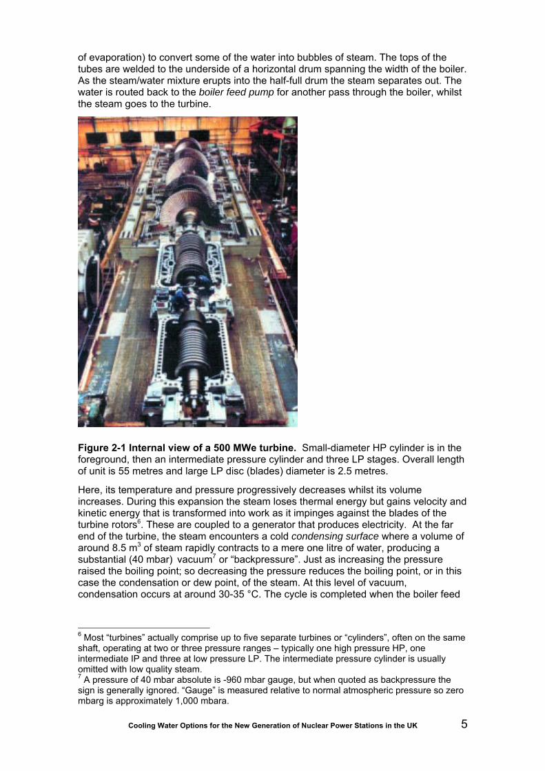
intake temperatures (10ºC ΔT) 181 Figure 2-1 Internal view of a 500 MWe turbine. Small-diameter HP cylinder is in the foreground, then an intermediate
pressure cylinder and three LP stages. Overall length of unit is 55 metres and large LP disc (blades) diameter is 2.5 metres. 5
Figure 3-1 Oldbury tidal reservoir: impounding wall is above level of falling tide 18 Figure 3-2 Aerial view of Turkey Point cooling canals 22 Figure 3-3 Spray cooling (photo courtesy Siemens Power Generation) 24 Figure 4-1 Diagram of typical direct CW system 38 Figure 4-2 Inshore Intake at Ballylumford B, Larne 41 Figure 4-3 Inshore Intake at Kilroot, Carrickfergus 41 Figure 4-4 Offshore intake and inshore outfall at Wylfa, Anglesey 42 Figure 4-5 Capped radial flow intake structures for Vasilikos, Cyprus 42 Figure 4-6 Bolted tunnel and shaft lining for Sizewell A 44 Figure 4-7 Precast offshore outfall conduits for Kilroot 44 Figure 4-8 CW pumphouse substructure under construction at Vasilikos, Cyprus 45 Figure 4-9 Inshore outfall structures for Heysham A and Heysham B 47 Figure 4-10 Model of submerged outfall for Kilroot 48 Figure 4-11 Diagram of typical indirect CW system 49 Figure 4-12 Configurations of natural draught cooling tower 50 Figure 4-13 Configurations of induced draught cooling tower 50 Figure 4-14 Typical hybrid tower arrangement 51 Figure 4-15 Diagram of typical direct CW system with ‘helper’ tower 54 Figure 5-1 Typical submerged intake structure 57 Figure 5-2 Temporary works for immersed tube construction, South Humber 60 Figure 5-3 CW intake at Keadby, showing overhead gantry rail for screen raking system and accumulated
brushwood 63

Cooling Water Options for the New Generation of Nuclear Power Stations in the UK ix
Figure 5-4 Top: passive wedge-wire cylinder screen in ‘T’-format. An internal core-tube with holes of varying diameters is used to obtain an even flow distribution across the screen surface (courtesy Hendrick Screens). Bottom: PWWC screen array for bankside use. 64
Figure 5-5 Engineering drawings of travelling band screen: vertical section (left) and elevation (right) 66 Figure 5-6 Characteristics and flow arrangements for travelling band screens in plan view: a) through-flow, b)
dual flow (UK and France), c) central flow (Germany) 67 Figure 5-7 Schematic showing in-to-out (UK) versus out-to-in (France) drum screen design concepts 68 Figure 5-8 Further comparison of out-to-in and in-to-out drum screen designs 70 Figure 5-9 Overhead view of typical set of four drum screens at a coastal plant 72 Figure 5-10 Inshore outfall at Vasilikos, Cyprus 78 Figure 5-11 Layout of Sizewell A and Sizewell B 80 Figure 5-12 Temperature drop with distance from discharge point for Sizewell B 81 Figure 6-1 Mesh size curves for screening fish of different body shapes (from Turnpenny and O’Keeffe, 2005, after
Turnpenny, 1981) 85 Figure 6-2 Bandscreen panel fitted with six-mm square woven stainless-steel mesh. The trash elevator is in the
form of a narrow ledge which does not retain water and is unlikely to properly retain larger or writhing fish such as eels. 86
Figure 6-3 Sorted sample of fish collected from power station screens (left). Catches at saltwater sites typically contain a wide range of species but are often dominated by pelagics, such as sprat and herring. The bulk of the catch is often made up of juveniles or smaller species of under 20 cm in length, although certain locations and intake designs can put larger fish at risk (right). 87
Figure 6-4 Coarse screen blocked by fouling 88 Figure 6-5 Estimated annual total quantities of fish impinged at UK estuarine and coastal power stations
(Turnpenny and Coughlan, 1992) 88 Figure 6-6 Examples of fish injuries caused by impingement. Left: bleeding into the eye is common as a result of
exposure to pressure change. Right: an eel with spinal fracture. 91 Figure 6-7 Effect of chlorine concentration on carbon fixation by phytoplankton at Fawley Power Station, Hampshire
(Source: Davis, 1983) 95 Figure 6-8 Percentage mortality of adult calanoid copepods within one hour of entrainment under various
chlorination regimes at four different UK power stations (Source: Coughlan & Davis, 1983) 97 Figure 6-9 Schematic of FARL Entrainment Mimic Unit (EMU) (after Bamber et al. 1994) 99 Figure 6-10 Equivalent adult value curves for common UK commercial species (Turnpenny, 1989) 102 Figure 6-11 Area of replacement habitat for entrainment losses against flow rate (plotted from data in Table 6-5) 105 Figure 6-12 Fawley Power Station CW intake at low tide, showing the onshore CW inlet channel and bordering
saltmarsh areas 107 Figure 6-13 Cefas Young Fish Survey data showing zonation of sole (Solea solea) relative to water depth 108 Figure 6-14 Schematic showing rising bubble plume and surface currents normal to the barrier line in a bubble
curtain 110 Figure 6-15 Schematic showing bubble curtain deflection concept for an offshore intake 110 Figure 6-16 Velocity cap: (a) section of uncapped intake showing vertical draw-down pattern, (b) section of capped
intake showing horizontal flow pattern, (c) as (b) but showing critical relationship between vertical opening [x] and length of horizontal entrance [1.5x] for fish reactions (after Schuler and Larson, 1975) 112
Figure 6-17 Concept design for a low-velocity, side-entry offshore intake structure with velocity cap, based on physical and hydraulic model tests carried out at Fawley Aquatic Research Laboratories Turnpenny, 1988a and unpublished). A and B are the cylindrical caissons. Water enters through C. 113
Figure 6-18 Schematic layout of a sound projector array (SPA) acoustic fish deterrent system with six sound projectors. Large systems may use up to 60 sound projectors, each with a dedicated amplifier and diagnostics unit. 115
Figure 6-19 Example of an acoustic fish deterrent support structure constructed across a shoreline CW intake at the Lambton Generating Station, St Clairs River, Canada. The vertical beams each act as rails, which allow sound projectors to be raised and lowered for maintenance. The positioning of the structure ahead of the intake opening ensures that the fish repulsion zone is in an area of low water velocities from which the fish can escape. The inset shows an individual sound projector. (Main photo courtesy Paul Patrick, Kinectrics). 116
Figure 6-20 Example of fish return launders. Launders should be covered to reduce predation risk. Larger radius (3 m) swept bends reduce the risk of debris and fish becoming caught in bends. 117
Figure 6-21 Streamlines around a travelling screen fish bucket (a) traditional, showing rotational flow and (b) modified to stall flow within bucket (Fletcher et al. 1988). Width of bucket opening is typically 60 mm in standard designs. 118
Figure 6-22 Example of a fish bucket profile. The mesh to the left represents part of one of the main screen panels (Eimco Water Technologies). 118
Figure 6-23 Fish that have overshot the hopper collecting on a scaffold boards inside a drum screen chamber 120 Figure 6-24 A thermal plume, made visible by alginate-induced foaming 129 Figure 6-25 Schematic vertical section through an offshore thermal plume showing the hydraulic processes
associated with dispersal. Close to the plume, where ΔT is highest, the water rises above the bed, so effects on benthos are usually small here. Further away, the plume mixes with the receiving water and rapidly cools. 130
Figure 6-26 Temperature preferenda, optimal growth temperatures and lethal temperatures for key UK fish species. Current UK water temperature standards are indicated by dashed vertical black lines. Suggested WFD boundaries are shown by dashed vertical coloured lines: green, high/good; blue, good/mod; orange, mod/poor. 150
Figure 6-27 Mortality of oysters in the River Blackwater, Essex, following the severe winter of 1962-63 (Turnpenny and Coughlan, 2003) 151
Figure 6-28 Percentage cover of Balanus balanoides (means with ranges; five replicates per station) for a transect of 10 sampling stations on the rocks leading away from Wylfa Power Station CW discharge (from Bamber, 1989). 153

Cooling Water Options for the New Generation of Nuclear Power Stations in the UK x
Figure 6-29 Monthly densities of A – Tubificoides amplivasatus and B – T. benedii in the CW discharge canal of Kingsnorth Power Station, at six sampling sites reflecting a gradient of mean ΔT from 9.2ºC at N5 to 0ºC at DC4 (after Bamber and Spencer, 1984) 154
Figure 6-30 Continuous seabed temperatures in Kingsnorth Power Station CW discharge canal over two weeks in December 1980, starting at high tide, for sampling sites DC1 (one km from the outfall), DC2 (1.7 km) and the control site DC4 (four km) 155
Figure 6-31 Numbers of benthic infaunal species in Kingsnorth Power Station CW discharge canal over three years; sampling sites K1 and DC1 to DC3 are within the canal, DC4 is the control site (after Bamber and Spencer, 1984) 156
Figure 6-32 Growth curves for Urothoe brevicornis for the 1967 cohorts at Hunterston Power Station beach (solid circles) and the control beach at Millport (open circles) (redrawn after Barnett, 1971) 159
Figure 6-33 Growth curves for Cyathura carinata populations from Kingsnorth Power Station discharge canal (solid circles), compared with populations from Arcachon (open circles), the Kiel Canal (solid squares) and the Polish Baltic (open squares) (after Bamber, 1985); horizontal bars indicate winters 160
Figure 6-34 Example of a temperature exposure time-series for a specific habitat extracted from the Delft 3D model, comparing surface and bed temperatures 162
Figure 6-35 Modelled cross-section of a thermal plume entering an estuary channel, extracted from the CFX-5 model. This shows the buoyant plume rising from the outfall structure (to the left). Note that most of the channel cross-section contains ΔT values of under +3oC, which would be suitable for fish migration. 163
Figure 6-36 Isometric plot from CFX-5, showing the behaviour of the thermal plume, in this case clinging to the foreshore along the left-hand-side of the plot. This type of plot can be used to explore the risk of creating a barrier to juvenile fish movement along the intertidal foreshore 163
Figure 6-37 Depiction of a diffuser outfall with ten discharge ports. Arrow indicates tidal flow (reversible). 164 Figure 6-38 CFX-5™ model outputs depicting dispersion of heat from a multiport outfall. (Upper: plan; lower, vertical
section) 164 Figure 7-1 Example of sampling facilities for impingement and entrainment monitoring. Upper drawing shows
diversion from FRR launder into water-retaining collection basket for impingement sampling. During sampling, shutters or gates are adjusted to divert flow into sampling well. Lower drawing shows the arrangement in vertical section, along with the suspended plankton net used for entrainment sampling. 178

Cooling Water Options for the New Generation of Nuclear Power Stations in the UK 1
1 Introduction
1.1 Purpose of study The Health and Safety Executive (HSE) and Environment Agency1 are working together to make sure that any nuclear power station built in the UK meets high standards of safety, security, environmental protection and waste management (Generic Design Assessment, GDA). There is a need to investigate cooling water options for new reactors and evaluate the environmental impact of these in terms of thermal, chemical and radionuclide pollution, and impact on biota. This document draws together information that will assist the regulatory agencies in this process.
1.2 Background Regulation of the nuclear power industry in the United Kingdom is the joint responsibility of the Environment Agency and the Scottish Environmental Protection Agency (SEPA) (environmental) and the Health and Safety Executive (nuclear health and safety), that now includes the Nuclear Installations Inspectorate. The Government is committed to allowing the construction of new nuclear power stations provided they are subject to the normal planning process for major projects (under a new national planning statement) and provided also that they receive no public subsidy. The Government will complete the drafting of a national planning statement and put it before Parliament and, if approved, clear the way for planning applications for new nuclear power stations. This policy creates new challenges for the regulatory agencies given the variety of options available, since the development of nuclear power stations is now open to commercial competition. Hitherto all nuclear design and construction has been under effective government control, via the former Central Electricity Generating Board (CEGB) or, until 1996, the state-owned Nuclear Electric (NE) plc. Sizewell B was commissioned before NE was sold-off as British Energy. A Strategic Siting Assessment of potential sites for nuclear new build has been carried out using exclusionary and discretionary criteria which were consulted upon publicly. This included a criterion on access to suitable sources of cooling. The Environment Agency advised the Government on whether sites were potentially suitable against this criterion. The public has been consulted upon whether sites are potentially suitable and the Government is currently considering responses to the consultation. Sites which are potentially suitable for deployment by 2025 will be listed in a Nuclear National Policy Statement. Should individual applications come forward for development consent, the Environment Agency will consider cooling as part of licensing with site specific detail. Most people would be astonished at the demand for cooling water (CW) imposed by a nuclear plant, or indeed any other thermal power station. Laws of thermodynamics dictate that for every megawatt of power generated, up to two megawatts must be discarded as low-grade (low temperature) waste heat. In fossil-fuelled plants such as combined-cycle gas turbine (CCGT) stations and the new generation of supercritical coal plants significantly higher efficiencies (above 45 per cent) can be achieved, and in some cases low-grade heat can be put to use in district heating schemes, commercial horticulture or aquaculture. For nuclear stations, however, thermal efficiencies remain relatively low (around one-third efficient) and opportunities for constructive use of waste
1 See Joint Regulators website: http://www.hse.gov.uk/newreactors (viewed 12/04/09)

Cooling Water Options for the New Generation of Nuclear Power Stations in the UK 2
heat around isolated sites are fewer. Thus, a nominal 1,000 MWe nuclear generating station must discard nearly 2,000 MW into the environment as waste heat. Heat disposal from thermal power stations can be into the atmosphere via cooling towers, via once-through direct cooling systems into surface water bodies and thence into the atmosphere or via hybrids that combine both methods. Direct cooling is the most efficient in terms of energy use, and therefore in terms also of greenhouse gas emissions. All UK nuclear stations built before today, and a large number of fossil-fuelled stations, discard their heat to water via direct cooling, the key reason favouring construction on the coast or estuaries.
Under the EU Integrated Pollution Prevention and Control 'IPPC' Directive (96/61/EC), the Environment Agency is obliged to consider, for designated installations, whether the technologies and techniques used by the developer would be Best Available Techniques or BAT. Technical guidance on BAT is given in BAT Reference or BREF notes. The European BREF document on industrial cooling systems (BREF Cooling; adopted December 2001) considers water cooling as the preferred option (as it helps reduce emissions of greenhouse gasses) and defines direct cooling as a BAT for large combustion plants in coastal locations, provided that the aquatic ecosystem is not adversely impacted. While nuclear power stations are not within the scope of the IPPC Directive, the BREF notes are useful to inform the Environment Agency’s discharge consenting process. OSPAR (Oslo and Paris Conventions) also requires the use of BAT when considering prevention and elimination of marine pollution. OSPAR covers discharges of radioactive substances2.
More recently, however, the validity of the BAT definition of direct cooling has come under challenge, owing to what some believe may be unacceptable environmental impacts on the source and receiving water bodies. Pressure on this issue has emanated largely from activities in the USA, where impacts arising from abstraction of cooling water are regulated under the Clean Water Act s.316(b). Legal actions brought against the US Environmental Protection Agency (EPA) by the pressure group Riverkeeper, Inc. have forced the EPA to act on this issue. In its 2004 decision in Riverkeeper v. EPA (Riverkeeper I), the Second Circuit upheld the EPA’s Phase I regulations, which set closed-cycle cooling systems (wet or dry tower-cooling) as BTA (best technology available) for new power plant cooling facilities3. In this case, the finding relates to effects of the abstraction only, and not of the discharge of heated effluents into the environment. In the UK, the validity of direct cooling as BAT for a new 2,000 MWe power station proposal falling within a Natura 20004 site, was investigated on behalf of the Countryside Council for Wales (Cambrensis, 2008). A key conclusion from the Cambrensis report was that, since the latest information to the 2001 BREF Cooling note was published in 1997, it is now out of date given developing techniques in indirect cooling. However, the same could be said of environmental mitigation techniques against abstraction impacts, an aspect which is not considered in the Cambrensis report. To give proper consideration to this issue, a thorough understanding of the technical background and the types and levels of environmental impacts are required, along with an appreciation of recent developments in cooling technology and associated mitigation techniques.
Effects upon the aquatic environment from direct cooling water systems, that is those that do not use cooling towers, relate primarily to two causes:
• The incidental capture of organisms contained in the abstracted cooling water stream: these may be divided into two components, the first caused
2 http://www.ospar.org/content/content.asp?menu=00220306000063_000000_000000 3 Riverkeeper I, 358 F.3d 174, 194 (2d Cir. 2004). 4 Milford Haven Special Area of Conservation
Cooling Water Options for the New Generation of Nuclear Power Stations in the UK 3
by impingement of fish and invertebrates on cooling water filter screens and the second, entrainment of mainly planktonic stages of fish, invertebrates and microscopic plants which pass through the screens through the cooling circuit, before being discharged back to the wild via the thermal discharge.
• The effects of the thermal discharge, which sometimes contains residual oxidants and byproducts from use of biocides (mainly chlorine-based) in the receiving water bodies.
Where cooling towers are used, these impacts are diminished but arise, for example, from cooling tower plume emissions and visual impact and increased energy use (or decreased efficiency of the power plant). This report helps to explain why and how water is used for power station cooling, what the technical options are and the main design considerations, types and levels of environmental impact and mitigation techniques now available.
1.3 Terms of reference The following objectives were established for this study:
1. to give a brief overview of all power station cooling water systems in use in the UK and abroad;
2. to identify and give details of all cooling water options for new nuclear power stations in the UK;
3. to give an overview of the generic environmental issues associated with cooling water systems of nuclear power stations (for example thermal, chemical and radionuclide pollution, fish and invertebrate intake);
4. to identify and explain any environmental issues associated with specific cooling water options;
5 to evaluate the cooling water options in terms of environmental concerns and assess the best options for different types of water body (coastal, estuarine and freshwater).
1.4 Sources of Information The study uses only publicly available documents and references, all of which are listed in the text or in the reference list at the end of the report. Where internet sources have been used, the dates on which these were accessed are given. A number of internal CEGB and power industry reports have been cited, which should be available from the British Library but are also held by Jacobs Engineering, Southampton Office.

Cooling Water Options for the New Generation of Nuclear Power Stations in the UK 4
2 Why power stations need cooling
2.1 Thermodynamics and the steam cycle Power stations are essentially factories that make electricity, the value of which exceeds the cost of its production. As with any manufacturing process, energy has to be used in making the product – but in thermal power stations two or three times more energy goes in, as fuel, as comes out as electricity. However, the versatility or quality of electrical energy is far more valuable in practical and monetary terms than the energy in the fuel. Few people could find much use for a lump of poor-quality coal or a bucket of residual fuel oil, let alone a chunk of uranium.
The benefits of electricity do not come without costs, the two most obvious and most heavily criticized being this low rate (efficiency) of conversion of fuel energy into electricity, and the associated discarding of unusable heat into waterways and the atmosphere. These issues - efficiency, water use and disposal of waste heat - cannot be understood without a brief look at the components and workings of a thermal power station and, particularly, some understanding of thermodynamics.
The First Law of Thermodynamics says that energy can be neither created nor destroyed but only converted from one form to another. Although the conversions might leave the total quantity of energy unchanged, the Second Law says that the quality of energy will decrease at each conversion and eventually becomes degraded to the point where it can no longer do useful work. For example, in hydroelectric generation there is more opportunity to obtain work from the potential energy in a small volume of water at 0.5 km altitude on a hillside than from a 1,000 times greater volume at 0.5 m above sea level. In this case it is the difference between the initial altitude and sea level that determines the utility of the energy. By analogy, the work that a steam turbine can extract from steam is determined by the difference between its inlet (heat addition) and exhaust (heat rejection) temperatures and, by this same analogy, there is more scope for extending the working temperature range upwards than downwards.
Thermal power stations use water as the working fluid in a four-stage vapour power cycle - the Rankine Cycle - during which it is alternately vaporised and condensed. Vaporisation (steam raising) needs heat. This comes predominantly from burning coal, oil or gas and to a much lesser extent from sewage and landfill methane, biomass, domestic refuse, solar and geothermal sources, and from the controlled splitting of uranium atoms in a nuclear (fission) reactor.
The power cycle is probably best visualised by reference to coal being burnt in a tube and drum boiler. The coal’s chemical energy is transferred, via the thermal energy (radiance) of flames and hot combustion gases (conduction), to water circulating under pressure through vertical steel evaporator tubes lining the boiler walls. Because of the pressure, the temperature at which the water boils5 is well above 100°C – for example, 450°C at 100 bar. Continued heating provides the latent heat of vaporisation (enthalpy 5 Water molecules are in a constant state of agitation. At room temperature and pressure, some molecules briefly burst through the water surface creating a small vapour pressure. With increasing temperature the molecules become more energetic, more escape the surface and the vapour pressure rises. When vapour pressure equals ambient (air) pressure more molecules are leaving the surface than are re-entering and the water boils. Increasing (or decreasing) ambient pressure raises (or lowers) the boiling point.
Cooling Water Options for the New Generation of Nuclear Power Stations in the UK 5
of evaporation) to convert some of the water into bubbles of steam. The tops of the tubes are welded to the underside of a horizontal drum spanning the width of the boiler. As the steam/water mixture erupts into the half-full drum the steam separates out. The water is routed back to the boiler feed pump for another pass through the boiler, whilst the steam goes to the turbine.
Figure 2-1 Internal view of a 500 MWe turbine. Small-diameter HP cylinder is in the foreground, then an intermediate pressure cylinder and three LP stages. Overall length of unit is 55 metres and large LP disc (blades) diameter is 2.5 metres.
Here, its temperature and pressure progressively decreases whilst its volume increases. During this expansion the steam loses thermal energy but gains velocity and kinetic energy that is transformed into work as it impinges against the blades of the turbine rotors6. These are coupled to a generator that produces electricity. At the far end of the turbine, the steam encounters a cold condensing surface where a volume of around 8.5 m3 of steam rapidly contracts to a mere one litre of water, producing a substantial (40 mbar) vacuum7 or “backpressure”. Just as increasing the pressure raised the boiling point; so decreasing the pressure reduces the boiling point, or in this case the condensation or dew point, of the steam. At this level of vacuum, condensation occurs at around 30-35 °C. The cycle is completed when the boiler feed
6 Most “turbines” actually comprise up to five separate turbines or “cylinders”, often on the same shaft, operating at two or three pressure ranges – typically one high pressure HP, one intermediate IP and three at low pressure LP. The intermediate pressure cylinder is usually omitted with low quality steam. 7 A pressure of 40 mbar absolute is -960 mbar gauge, but when quoted as backpressure the sign is generally ignored. “Gauge” is measured relative to normal atmospheric pressure so zero mbarg is approximately 1,000 mbara.

Cooling Water Options for the New Generation of Nuclear Power Stations in the UK 6
pump injects the condensate back into the base of the boiler, adding mechanical energy (pressure) to the system.
The cycle cannot continue unless the latent heat given up to the cold surface during condensation is removed continuously from the system. This is where the cooling water is needed. The volume of cooling water required is determined by the weight of steam to be condensed. Consequently, increasing the amount of work that can be got out of each kilogram of steam (efficiency) before it has to be condensed enables more electricity to be generated for a given volume of cooling water and, crucially, reducing the quantity of heat discharged to the environment. The condenser-cooling water does not come into contact with surfaces at temperatures above 35°C.
2.2 Improving efficiency Improving conversion efficiency is probably the simplest way to minimise heat rejection. “Simplest” does not refer to the technological challenge, but to the political will to carry it through. Since conversion efficiency determines fuel consumption there is a strong financial incentive involved that, fortuitously, coincides with the IPCC BAT for cooling - to minimise the need for cooling by improving process efficiency. At 33 per cent thermal efficiency, 7.3 MJ of heat is rejected per kWh electrical output, falling to 6.4 MJ kWh at 36 per cent thermal efficiency. Strategically, the most thermodynamically efficient equipment need not necessarily be the best option; similarly, the balance between current and predicted interest and discount rates, between capital and lifetime running costs and between reliability and efficiency all can influence choice.
2.2.1 Theoretical efficiency
The maximum theoretical efficiency of most of today’s large sub-critical steam turbines is around 60 per cent (Table 2-1) although in practice this is reduced by heat losses and friction. If the losses at every step, from boiler to generator, are included then the overall efficiency of conversion falls to around 40 per cent. This may look poor but is a great advance on the 11 per cent attained pre-1918 and 20-25 per cent in the 1950s. By way of comparison the last railway steam locomotives were about 12 per cent efficient and typical modern petrol and diesel engines are 20-30 per cent efficient.
Table 2-1, calculated using a standard rejection (exhaust) temperature, shows not only an increasing theoretical efficiency for turbines over time but also a convergence between this and the station’s overall generation efficiency. These improvements have been possible through better understanding of theory and better design, coupled with new alloys and materials that tolerate higher temperatures and pressures.

Cooling Water Options for the New Generation of Nuclear Power Stations in the UK 7
Table 2-1 Improvements in theoretical efficiency and in performance, using a constant 35°C turbine exhaust temperature
Turbo-generator rating
and approximate
date
Steam inlet temperature
Carnot cycle efficiency
(theoretical)
Typical overall
generation efficiency
Ratio of overall to
theoretical efficiency
MW Date °C °K % % %
11 ~1914 345 618 50 ca 15 30 30 ~1929 370 643 52.1 20 38 46 ~1949 441 714 56.8 22.4 39
120 ~1962 538 811 62 32.1 52 660 ~1982 541 814 62.2 36.9 59 500 ~2000 600 873 64.7 40 62 Supercritical 700 973 68.3 45 66
These developments have proceeded in parallel with the use of larger boilers, turbines and generators. In fact, increased size (ratings) and better steam conditions are complementary and mutually dependent; it would be as uneconomic to build a 30MWe unit to operate at 540°C/160 bar as building a 660°C MWe unit to operate at 350°C/40 bar. The driving factor behind this progression is economics – again best illustrated by coal-fired stations where fuel represents about 95 per cent of the production cost (Table 2-2 – after Tombs, 1978).
Table 2-2 Increasing production (kilowatt-hours) from one tonne of coal
Date kWh generated per tonne of coal burnt
1900 ca. 200 Pre-1914 555 1920 641 Pre-1939 1,591 1977/78 2,088 2000 Drax 2,700 2001 Aberthaw B 2,654 2001 Didcot A 2,652
An efficiency gain of even a fraction of one per cent translates into significant savings, bringing benefits right across the environment, since not only is less cooling water abstracted and less heat rejected but also, in the above example, less coal has to be mined and transported; less ash, carbon dioxide, sulphur dioxide and nitrogen oxides are emitted. To date, fuel cost is less of an issue for nuclear stations.

Cooling Water Options for the New Generation of Nuclear Power Stations in the UK 8
2.2.2 Superheating, reheating and regenerative heating
The steam cycle described in Section 2.1 is basic and many modifications can improve efficiency. The boiler drum delivers saturated steam at the temperature and pressure of the water from which it was separated. Any slight decrease in temperature or pressure, as will inevitably occur en route to the turbine, will result in condensation and the formation of droplets that, for a variety of reasons, are undesirable. This can be avoided by first passing the steam through a moisture separator or, more commonly, a bank of superheater tubes in the hottest part of the boiler. Any carried-over droplets are evaporated and the steam temperature is raised, without change of pressure, far above its saturation temperature at this pressure. It now behaves as a gas and obeys the ideal gas laws relating temperature, pressure and volume. Superheating also adds more thermal energy to the steam, thereby further increasing its capacity for work in the turbine where its expansion, accompanied by the release of this superheat energy, proceeds until it reaches a saturated condition. Steam leaving the first (high-pressure) cylinder of the turbine is often passed through reheater tubes in the boiler before entering the intermediate pressure cylinder, following which it may undergo a second reheat. For a given energy input, the output (efficiency) can be increased by selectively boosting temperatures along the water-steam cycle. Steam is also bled off at various positions between the boiler and condenser for a range of ancillary heating purposes and, when practically all of its sensible heat has gone, latent heat is recovered by injecting it into the cold condensate returning from the condenser to the boiler. This regenerative preheating not only improves steam-cycle efficiency but, by condensing a significant weight of steam directly into the condensate, also reduces heat rejection via the cooling water. In a typical 500ºMWe conventional unit (Fawley) 32 per cent of the steam applied to the turbine does not enter the condenser, whilst Leizerovich (2005) suggests that 45 per cent of the steam flow from a pressurised water reactor (PWR) is used in reheaters and regenerative heating.
2.2.3 Efficiency and size
Since the early days of the industrial revolution, it has been known that the cost of a machine is roughly proportional to its weight, and that weight and size do not increase pro rata with output. This means that the pumps, boilers, turbines and generators require relatively smaller sites, foundations and buildings. Apart from reducing capital costs, increasing the size of a machine can increase its efficiency by reducing heat losses and friction. The first (1890s) power stations cost, at current prices, about £9,000 per kW of installed capacity but by 1965 the cost, of vastly more complex and efficient equipment was around £900 per kW.
The progression to larger units, with higher temperatures and pressures and lower cooling water requirement, has not proceeded uninterrupted. In 1947, to speed postwar reconstruction, UK procurement was standardised around 30 and 60 MWe units (350°C/40 bar), increasing to around 120 MWe (530°C/100 bar) and to 350 MWe by the end of the 1950s. From the mid-1960s, 500 and 660 MWe units (540°C/160 bar) were specified for new conventional stations. However Magnox (GC1 nuclear) stations, commissioned between 1955 and 1973, had low design steam conditions (350°C/48 bar at Bradwell) because their fuel elements were limited to under 450°C. This required turbines similar to those installed from the 1920s to 1940s. AGR (GC2 nuclear) stations have gas temperatures around 640°C and design steam conditions and cooling water requirements comparable with contemporary conventional plants, using similar 660 MWe units. Sizewell B PWR, commissioned in 1995, represented another reversal of the higher pressure/higher temperature trend, using a pair of modified 660 MWe units operating at 282°C/66 bar. In the UK there are no units larger than 660 MWe,

Cooling Water Options for the New Generation of Nuclear Power Stations in the UK 9
although there are many overseas, and no units operating supercritically above 221 bar - the so-called “critical pressure” for water (see Glossary).
2.2.4 Supercritical operation
The boiling point (saturation temperature) of water increases with pressure up to 221 bar - the critical pressure. At this pressure, the boiling point is 374°C but this remains unchanged by any further increase in pressure. Thus 374°C is the highest temperature at which liquid water can exist since, at and above the critical pressure, no latent heat (enthalpy of evaporation) is needed to convert liquid water to vapour [contrast this with the 2,258 kJ kg-1 required at atmospheric pressure]. “Supercritical” is a thermodynamic term describing this state where there is no clear distinction between liquid and gaseous phases.
One advantage of supercritical operation is that the boiler tubes yield a single phase fluid that can pass directly to the superheater, enabling once-through steam generators8 to be used. There is no need for a heavy, thick-walled drum to separate water from the steam.
No current design of nuclear power station operates supercritically9 and lightwater reactors (PWRs and BWRs) in particular operate far below it (under 70 bar). However the Environment Agency will be assessing proposed supercritical coal-fired plant, such as the 2 x 800 MWe Kingsnorth B and Tilbury B stations, and comparisons will be drawn with the relative volumes of cooling water required by nuclear stations. Although no existing UK conventional stations operate supercritically, 375 MWe supercritical units were operating at Drakelow C (UK) in 1960, with steam conditions (595°C/250 bar) comparable with the most advanced units available today. However, lacking the benefit of today’s materials, they had poor reliability whereas current state-of-the-art supercritical coal-fired plants have a reliability comparable with subcritical plant and efficiencies above 45 per cent. Indeed, ultra-supercritical plants, operating at 700°C/350 bar with 720°C reheat and approaching 50 per cent efficiency are now considered feasible (DTI, 1999).
2.2.5 Nuclear thermal cycles
In PWRs lightwater10 serves as the moderator and primary coolant. The fuel elements heat it to about 320°C but it does not boil since it is held under pressure (150-170 bar). It passes from the reactor to the base of a vertical, cylindrical steam generator and circulates through inverted U-tubes in the middle (evaporator) section where it transfers heat to feedwater in the secondary coolant circuit before returning to the reactor at about 290°C. The pressure on the secondary side of the U-tubes is around 69 bar, so the feedwater boils. This steam/water mixture enters the upper section of the steam generator, passing first through a steam separator (moisture separator) that imparts a spin to remove the larger entrained water droplets and then through steam driers. The driers comprise a series of angled louvres (chevrons) in which the steam flow is forced to make several sharp changes in direction, throwing droplets into contact with their surfaces. The dry steam (about 0.25 per cent water content or 99.75 per cent steam quality) enters the HP turbine in a nearly dry saturated condition but becomes wet as it expands. At Sizewell PWR (282°C/67 bar) additional moisture separators are sited
8 “Boiler” seems inappropriate since no boiling occurs. 9 The Canadian CANDU X will operate supercritically but will not be in commercial operation before 2020. 10 Ordinary H2O, as distinct from heavy water D2O.

Cooling Water Options for the New Generation of Nuclear Power Stations in the UK 10
between the high-pressure (HP) and low-pressure (LP) cylinders, together with reheaters, heated by steam bled directly from the steam generator. This avoids excessive wetness that would erode the LP blades11 enabling LP cylinders similar to those of standard 660 MWe sets to be used. The Wolf Creek and Callaway (USA) four-loop SNUPPS12 stations, on which the Sizewell design was based, use a single 1,300 MWe turbogenerator operating at half-speed (1,800 rpm for 60 hz) to reduce tip speed and erosion of the LP blades.
In boiling water reactors (BWRs) lightwater is the moderator and only coolant. The internal layout of the reactor vessel resembles the steam generator of a PWR in that it is only part-filled by water. The submerged fuel elements heat the water to some 290°C that, since the reactor is at a pressure of about 70 bar, causes it to boil. The water-steam mixture passes through separators and driers located above the core, before being fed into the turbine. Steam conditions for PWRs and BWRs are physically very similar but the latter can carry contamination into the turbine and condenser.
With AECL CANDU13 out of contention, UK regulators are considering a PWR design by Areva-EDF; another PWR by Westinghouse and a BWR design by General Electric-Hitachi.
2.3 The role of the condenser It was noted, in section 2.1, that the condensation of exhaust steam creates a vacuum (backpressure) that increases generation efficiency. Hence the cooling system must be capable of continuously and consistently rejecting the heat load necessary to maintain the condensation temperature corresponding to the optimum turbine backpressure. For a given steam flow and cooling water flow, the basic design (and operating) parameter for the condenser is the temperature of the incoming cooling water, which is variable. However the condenser must remain capable of transferring the necessary heat load even in summer. Undercooling - operating above the design point - decreases efficiency and leads to frictional heating and expansion of the last-stage turbine blades (this can result in loss of clearances) as they rotate through an over-dense atmosphere of steam. Overcooling - operating below the design point - might increase efficiency but at the risk of extending the condensation zone into the turbine, causing droplet erosion of the blades. Moreover the intention is to condense steam, not to cool the condensate as it drips down through the tube bank: any heat lost here will have to be replaced by the boiler. In any case, once the velocity of the steam through the turbine exhaust passages reaches sonic velocity (choking flow) there is no further backpressure gain to be made. Inevitably such considerations result in a series of trade-offs in turbine and condenser design reflecting capital and running costs across a range of conditions.
Condenser performance is also reduced by factors such as scale on the outside (steamside) of the tubes and by slime and scale (waterside fouling) inside. These effectively insulate the tube wall. A major backpressure problem for some condensers is steamside air ingress. Air can outgas from the boiler feed water during intermittent operation and also be pulled in around the LP turbine exhausts and past flange seals on the waterbox doors. Condensers need vacuum pumps to remove air from the 11 Since there is less energy in the steam, LP blades must be longer than HP blades and, at 3,000 rpm (50hz) the tips may be travelling at 350 ms-1 and are prone to erosion and unbalancing by impact with water droplets. 12 Standard Nuclear Unit Power Plant System. A Westinghouse design having four steam generators (four-loop). 13 AECL Atomic Energy of Canada Limited; a second-generation heavywater cooled and moderated reactor. Withdrawn from UK selection process in March 2008.

Cooling Water Options for the New Generation of Nuclear Power Stations in the UK 11
turbine cylinders and condenser when the unit is started up, but it is not uncommon for them to have to be run continuously. Air is non-condensable and accumulates at the top of the condenser, preventing steam from reaching the top rows of tubes (air blanketing). When the system is unable to reject the heat load necessary to achieve a steam condensate temperature corresponding to the optimum design turbine backpressure there are two penalties:
• Efficiency loss – for a given fuel input, the electrical output is lower. An increased heat rate (fuel burn) would be needed to restore output.
• Capability loss - the unit cannot handle the design heat input (steam flow) within the backpressure limit .The steam flow must be restricted to restore the backpressure, so the generator does not reach its rated value (loss of output).
2.3.1 Can a thermal power station work without steam?
In theory, yes. Water is not the only working fluid although it has many advantages. Alternative fluids (such as ammonia and a variety of organic compounds) all are more expensive and have one or more of the hazards conspicuously absent from water. However, an organic Rankine cycle (Karellas & Schuster, 2008) can use low temperature heat sources and be efficient in small-scale applications. Most proposals envisage using these fluids to boost parts of the Rankine steam cycle, rather than wholesale substitution for water. The highest primary coolant temperature in existing large nuclear stations is 640-650°C (gas in UK AGRs) but prototype high temperature gas reactors (HTRs) using ceramic fuel indicate that far higher temperatures are feasible and could be used to run gas turbines. The gas would expand and cool in the turbine and the exhaust would be recycled to the reactor.
2.3.2 Is water essential for cooling?
No, but it is extremely effective and very convenient. The ultimate heat sink is the atmosphere (moist air) so the choice of coolant is water or air. Water has a high specific thermal capacity and is able to absorb large amounts of heat with little increase in temperature, whereas the thermal capacity of air is a quarter that of water (1.0035 J kg–1 against 4.186 J kg–1). Moreover its density is 830 times less. It is seldom economic to build coolers (essentially car radiators on a grand scale) of sufficient size for the recool temperature to closely approach air (dry bulb) temperature. Consequently air-cooling is the most efficient and least-cost option only when air temperature is very low for much of the year or when the temperature of the fluid to be cooled is above 55°C. Even so, dry cooling is used for power stations, even in areas where adequate water is available (section 2.4).
2.4 Principles of cooling Heat transfer depends on the existence of a temperature gradient. In the condensers discussed above, steam at about 30°C impinges upon cold (say 5°C to 20°C) water-filled tubes where it condenses, dumping its latent heat in the film of water on the tube surface. This heat is conducted across the tube wall and into the cooling water. The following options are discussed in more detail in the next chapter (3).

Cooling Water Options for the New Generation of Nuclear Power Stations in the UK 12
2.4.1 Direct (once-through) wet cooling systems
In a direct system the cooling water is discharged, dispersed and diluted in a river, lake or sea. Ideally none of the discharge finds its way back to the intake, or at least not until its temperature has been reduced to near-ambient. The ultimate heat sink is the atmosphere, via convective and evaporative transfer from the water surface - a process that is enhanced by wind and waves. This is the least complex, generally most thermally efficient and often cheapest option, with the added advantage of being visually unobtrusive. In some cases a lake is “engineered” by means of bunds to create a longer path between outfall and intake – indeed the lake may have been created for just this purpose – although it may acquire secondary functions such a recreation and water storage. Cooling canals are a linear lake, with the water following a tortuous path from the outfall to the intake. The cooling capacity of lakes and canals can be increased by agitation of their surface and by fountains (sprays) that increase the effective surface area for sensible (contact) cooling and for evaporative cooling (Section 3.1.4).
2.4.2 Indirect (recirculating) wet cooling systems
With indirect cooling, the transfer of heat to the atmosphere is accomplished within the cooling circuit. Most large recirculating circuits use wet towers. These improve upon the sprays described above by creating a directional air flow and by maximising air contact with the falling water droplets. This enables the cooling pond to be reduced to no more than the basal area of the tower, with a significant decrease in the volume of water held in the circuit. A wet tower is not only cheaper to construct than a dry system but it also provides lower recool temperatures and needs less maintenance. The degree of cooling depends upon the wet bulb temperature of the air (Twb). A low Twb indicates cool air, low humidity or some combination of these; the lower the Twb the greater the scope for evaporation and evaporative cooling. Towers can function even when the inlet air is at its wet bulb temperature since the air entering the tower is warmed (sensible heat) by contact with the water, thereby raising its temperature so that it is no longer saturated. The minimum recool temperature would be the wet bulb temperature of the air entering the tower (100 per cent wet bulb performance). In practice this can never be realised and even at low wet bulb temperatures a 65-70 per cent performance is considered good.
At the design air:water loadings, the cooling range of a tower (cooling water inlet temperature minus the outlet or recool temperature) is relatively immune to changes in wet bulb temperature. The difference between the wet bulb temperature and the recool temperature is described as the cooling approach or just approach. A high air:water ratio needs a large tower and large airflow, but permits a close approach to wet bulb temperature.
2.4.3 Natural draught towers
In a natural draught tower the tower shell extends high above the pack (wet section) and functions as a chimney, with the convective rise of warmed air drawing in cooler air at the tower base. With most natural draught towers, there is little if any scope for air control and this often results in overcooling. Conversely, should the air temperature (dry bulb) exceed the temperature of the inlet water, the air flow will stop. A hybrid tower 14 - a natural draught tower that can be assisted by fans at the base - has a greater cooling capacity than a natural draught tower of similar size.
14 Various other systems are also now described as “hybrid”.

Cooling Water Options for the New Generation of Nuclear Power Stations in the UK 13
2.4.4 Mechanical draught towers
Mechanical draught towers rely on fans to push or pull air through them, which gives a more consistent air flow than in natural draught towers though the fans increase the running costs. By using internal doors and/or variable speed or variable pitch fans, the performance of such towers can be matched to prevailing atmospheric conditions. One disadvantage of the low profile of mechanical draught towers is that any plume of vapour or drizzle emerging from the top of the tower is closer to the ground than with a natural draught tower. Where this is seen to be a problem, a dry section (radiator) can be built above the wet section to raise the saturation temperature of the plume. In some climates, the tower can operate for much of the year using the dry section alone.
2.4.5 Dry coolers and condensers
As the name suggests, the water does not contact the air – as in a car radiator. Heat is transferred to air by conduction as sensible heat or “heat that can be felt”. Since heat transfer depends upon the existence of a temperature gradient, the recool temperature will always exceed air temperature (dry bulb temperature - as given in weather forecasts). With an infinitely large radiator and unlimited air to pass through it, it would be possible for air and recool temperatures to approach to within a fraction of a degree. In practice, a balance must be struck between the benefits of a lower recool temperature and the size/cost of the radiator. Air cooling can be used for condensing, not just for cooling. This was originally used for relatively small-scale applications but increasingly is being used for multi-megawatt power plant. As a rule, air cooling is the most efficient and lowest cost option where the input temperature is above 55°C and the year-round air temperature is low. It is possible to lower the recool temperature and to reduce the size of an air/water cooler by spraying water over it (WSAC - wet surface air cooling). As the water evaporates, it removes latent heat from the cooler surface.
2.5 Economics For many years, the main reason for choosing tower cooling for a power station was that insufficient water was available or readily accessible for once-through cooling. In some cases this was seasonal and towers were brought into use only in summer. The evaporation of one kg of water removes sufficient heat to cool 100 kg of water through 10°C; thus at minimum a tower cooled station need abstract only one per cent of its circulating volume. In practice about three per cent is usually abstracted, of which one per cent is evaporative loss and the other two per cent is discharged back to the waterway to prevent build-up of dissolved and suspended solids in the circuit. However, a whole raft of considerations must be taken into account, some of which might appear retrograde in terms of technology or efficiency. Tower cooling permits more flexible siting, thereby reducing fuel transport and/or transmission costs, and increasingly is seen as a way of avoiding potential delays and litigation sometimes associated with licence applications for direct cooling. Against this are the higher capital costs for towers although these costs might be marginal when set against emplacing or tunnelling large diameter pipes for direct cooling. Similar, and often more severe penalties, attach to the use of air coolers and condensers. Running costs, particularly for mechanical draught towers and air coolers, are higher than for direct cooling and there is less thermal efficiency (higher backpressure) and, for conventional plant, greater carbon emissions because of higher cooling water temperatures at the condenser inlet. However, the turbine LP section can then be cheaper, with fewer, smaller diameter discs and a corresponding reduction in the dimensions of the casing

Cooling Water Options for the New Generation of Nuclear Power Stations in the UK 14
and exhaust steam passages. These economic arguments need to be weighed in each case.

Cooling Water Options for the New Generation of Nuclear Power Stations in the UK 15
3 Existing power station cooling systems
3.1 Critical review and description of alternative cooling circuits
3.1.1 Summary of large (above 1,000 MWe) UK cooling circuits
Appendix A provides a list of large UK power stations, along with details of their cooling systems. Reference is made to UK stations throughout the following text.
3.1.2 Cooling requirement
The previous chapter outlined how steam-electric power stations make use of the Rankine cycle, of which condensation is an essential stage. During condensation the enthalpy of evaporation (latent heat) of the steam is released and the cycle cannot continue unless this heat is removed from the system, which is most commonly and efficiently done by cold water flowing through tubes in surface condensers. Higher temperature heat sources enable a greater percentage of the heat to be converted to electricity, leaving less waste heat to be discharged. Similarly, lower temperature cooling water will also yield higher efficiency so a power station on the UK North Sea coast is more efficient than an identical one on the Gulf Stream-warmed south and west coasts. The volume of cooling water that is required is determined by the weight of steam to be condensed. Improved technology and metallurgy has steadily increased the amount of work (units of electricity) that can be generated from each kilogram of steam. This progression was driven by economics: primarily the cost and availability of fossil fuels. Fuel costs are less important for nuclear stations and, for technical and economic reasons, heat rejection (per unit of electricity) by lightwater reactors is high.
The principles involved in the layout and hydraulic performance of cooling circuits are considered in Chapters 4 and 5. Basically, the requirement is to deliver an uninterrupted, adequate supply of cold water to the heat exchangers and then to remove it and its reject heat. About 90 per cent of the water passes through the main cooling water system (MCW) to the condensers, with the balance entering supplementary or auxiliary cooling circuits. The layout, duties and names of these circuits vary from station to station. Increasingly stringent design at nuclear sites has necessitated the provision of discrete essential (reactor) cooling water systems (ECW or RCW). Most of these systems incorporate additional finer-mesh pressure strainers to protect small-bore coolers or plate heat exchangers (PHEs).
This chapter follows the order set out in Appendix B and is arranged more or less in order of decreasing water demand. The first section (3.1.3) considers the CW intake arrangements, mainly with reference to UK stations, and is broken down according to water source, whereas subsequent sections ignore the source and focus on the equipment.

Cooling Water Options for the New Generation of Nuclear Power Stations in the UK 16
3.1.3 Direct cooling
Intake position
This section gives a brief overview: engineering design aspects are detailed in the next chapter. Intakes in the sea or an estuary may be sited onshore, typically set flush into a quayside or seawall (Heysham A & B, Kingsnorth, Torness and Hartlepool) or at the head of a short canal (Fawley, Dounreay PFR). Most onshore intakes have a dredged channel leading to them that may or may not be shared with ships. Nearshore intakes are often at the end of a short jetty, with shafts and tunnels connecting them to the onshore CW pump forebays (Hunterston); Wylfa intakes are close to a jetty, but are not part of its structure. Offshore intakes have long tunnels from land, terminating either at a massive intake structure (Aberthaw, Hinkley Point A & B) or at downshafts (plug holes) in the seabed (Dungeness A & B and Sizewell A & B). These latter may be marked by a buoy or be surmounted by a platform (Sizewell A and, originally, Dungeness A). There is no hard and fast distinction, such as distance, depth or design between an offshore and a nearshore intake, but both types are surrounded on all sides by water.
Siting an offshore intake also has to take account of local factors such as proximity to shipping channels or fishing grounds and, if at the seabed, the need to mark it by buoy or a permanently lit topmark. It must not endanger swimmers, divers, sailboarders and small boats. Over the years, offshore intake design has been scaled down in size and complexity, partly in response to changing views on the need to isolate and dewater the shafts and tunnels for inspection and maintenance, but also to developments in diving and submersible vehicles that obviate the need to dewater.
Offshore seabed intakes
These usually have a vertical shaft that extends a metre or so above the seabed, so as to avoid drawing in mobile sand and gravel, with a cage-type screen on top to keep out trash (“parrot cage and plughole”). “Plughole” refers to the predominantly downward direction of the incurrent. These days it is more usual for the top edge of the shaft to have a horizontal lip extending to about twice the shaft diameter, with a solid “velocity cap” of the same diameter set about one metre above it, so that the incurrent becomes horizontal. The circumferential gap is protected by vertical bars to exclude trash. The bars may be welded into panels and fixed to the pillars supporting the cap or be set individually into the concrete at top and bottom. At Wylfa, the bars extend through the cap and can be withdrawn for maintenance. The Dungeness A and Sizewell A intakes were surmounted by platforms resembling small oil rigs on which stood a crane for removing the protective cages and lowering the shaft plugs stored on deck. The Wylfa intakes can be serviced from the nearby jetty; the shaft plugs remain underwater where they form part of the intake caps. Sizewell B intake is fully submerged and has no provision for isolation and dewatering. This decision was based on findings that during the previous thirty years few stations had needed to dewater their tunnels. Although Wylfa dewatered their tunnels “regularly” during statutory outages, Bradwell had done so “once or twice” but Sizewell A and Dungeness A had never done so. In fact the Dungeness platform was removed in the late 1980s, having become structurally unsafe - its crane had been condemned many years earlier.

Cooling Water Options for the New Generation of Nuclear Power Stations in the UK 17
Offshore headworks
Headworks such as Hinkley and Aberthaw are massive concrete structures, each designed to service more than one station (three at Hinkley) and can be reached on foot by a service tunnel. Both are surmounted by a crane for handling the removable grilles (guard screens) and stop gates. The central cylindrical concrete caisson of both structures was built on the nearby beach, floated out and sunk in position, after which the intake tunnel bores were completed and mated with the tunnel stubs on the caisson. The Hinkley structure was excluded from the previous (1980s) proposed C-station design since it would have been approaching 100 years old by the time that station was decommissioned. At Bradwell and Berkeley, the interlocking sheet piling of the construction caissons for the four intake (and outfall) shafts are incorporated into the final structure. Additional piling extends upstream and downstream as a “barrier wall” to prevent prompt recirculation of warm effluent. Both structures were equipped with gantry cranes for handling bar screens and the plugs (at Bradwell) and stop gates (at Berkeley) were stored on deck. The Berkeley tunnel access proved invaluable when the station was required to deploy 25 mm mesh smolt screens that required daily raising and cleaning over a six-week period every year.
Inshore headworks
The inshore (lower Thames) intake of Littlebrook D is a cylindrical sheet-pile tower that served as the caisson during excavation of the downshaft and tunnel. It is 20 metres in diameter with intake apertures around the entire circumference, covered by liftable 100 mm pitch bar screens. Grain (Medway) has a large rectangular concrete structure with two intake downshafts set in its base slab, 1.5 m above which is a solid “lower deck”. Around the periphery are liftable 250 mm pitch bar screens. The lower deck reduces the risk of vortex formation and the drawdown of floating oil and trash at low water. The two Hunterston stations and Longannet and Tilbury C have their intakes under a jetty, to the piles of which are fixed the guides for the liftable bar screens. Longannet has a fixed grille of 75 mm rods at 250 mm pitch to intercept and deflect heavier trash from the liftable 75 mm pitch bar screens immediately behind.
Onshore intakes
At many stations, these are “dead ends” where the cooling water is drawn into a confined channel towards a row of screens set across its path. Dounreay PFR and Fawley are probably the most extreme examples of this layout. At Heysham the intakes for the two stations are set at right angles to one another in the corner of a sheltered commercial harbour. There is a similar arrangement at Peterhead, although on a far smaller scale. Torness and Pembroke intakes are set in sheltered embayments, out of the main tidal flow and at Hartlepool the intakes are recessed deeply into the quayside. At none of these stations is there any possibility of trash being carried away from the screens by the tide. Only at Cockenzie and Kingsnorth, where the intakes are set flush with the dockside or seawall, is there any possibility of a flow across the face of the screens, and then only at high water when the surrounding mudflats are submerged. At both of these stations the incoming water is confined to a dredged channel at low tide. At Fawley there is an additional input of trash on a falling tide since the dredged channel intercepts many lateral creeks draining the surrounding saltmarshes.

Cooling Water Options for the New Generation of Nuclear Power Stations in the UK 18
Tidal reservoirs
The only UK example of a tidal reservoir is at Oldbury-on-Severn (
Figure 3-1) and no overseas examples were found.
Figure 3.1. Oldbury tidal reservoir: impounding wall is above level of falling tide
The mean spring tidal range in this part of the Severn is 11.3 m and the extreme range is 13.9 m (Extreme Low Water (ELW) is -4.7 m below Ordnance datum (OD). Given that the banks and channels in this reach are unstable, there was uncertainty over where to site the intake. An 8 km impounding wall (top +1.2 m OD) was built out on the mudflats to create a 200 hectare reservoir from which the cooling water is drawn. The design datum for the station’s hydraulic gradient, and the minimum immersed depth for the drumscreens and CW pumps, is zero metres OD, so the extreme tidal range is limited to 9.1 m or less if the reservoir is not fully drawn down. When the tide falls

Cooling Water Options for the New Generation of Nuclear Power Stations in the UK 19
below the top of the wall, approximately 2.4 million cubic metres are retained above datum (the “empty” level for operational purposes) that is sufficient for about 23 hours running on all four CW pumps or about 10 hours had the second station been built.
Water is abstracted through a wharf-type intake near the SE corner of the reservoir and discharged, via buried culverts, to outfalls outside the NW corner. Water can be recycled back into the reservoir by means of a variable crest weir on the southern outfall. When the tide rises above +1.8 m OD virtually all of the water from this outfall is recycled but since the wall has by then been overtopped by 0.6 m, the effluent is swept out of the impoundment. A recurrent problem has been that the reservoir acts as a settling pond. This was of little consequence when the accretion occurred in the “dead space” below the zero metre OD level but deposition was uneven and mud banks formed that threatened to cut off intakes. The solution was to use a pontoon-mounted pump to re-suspend sediment during the run of the tide so that it would be carried out of the reservoir, augmenting the natural tidal resuspension and deposition cycle.
River intakes
There are no UK rivers capable of cooling large (above 1,000 MWe) direct-cooled stations in their freshwater reaches. Even some tower-cooled stations (such as Willington, Notts, 800 MWe) found that during periods of low flow, a stretch of the Trent could flow upstream from outfall to intake. Since power station cooling is essentially non-consumptive the key issues tend to be environmental, such as effects on fisheries, rather than about water usage. In the USA power stations and agriculture each account for some 40 per cent of freshwater abstraction, although this becomes three and 81 per cent if consumption, rather than withdrawal, is considered (Feeley et al. US DoE, undated). In parts of the USA and continental Europe, ice must be added to the list of potential hazards at intakes.
Lakes/reservoirs
This section includes impoundments and natural lakes that are used for direct cooling. In some cases, the heat loading is insufficient to raise concerns about substantial ecological change but others are, in the words of the 1976 US Federal Register, simply recirculating cooling water bodies to which heat can be discharged without limitation. These latter would come into the category of “off-stream” cooling, along with spray ponds and cooling towers, but no examples have been found.
The design of cooling lakes and ponds seems to have been empirical and based on rule-of-thumb estimates such as one megawatt per acre (227 W m-2) or on an average rate of heat loss of 70 Btu15 per square foot per hour (220 W m-2). Kent (1938) reckoned that the heat dissipated from a still pond averaged 3.5 Btu h-1ft2 per °F temperature difference between the water surface and air. This would rise to 35 Btu h-
1ft2 given a temperature differential of 10 °F (5.5 °C) and would double with a windspeed above 2.2 ms-1 (five mph). Chen et al. (1988) give a useful outline of the basic principles whilst Adams et al. (1990) deal with more complex issues. Lakes lose heat to the atmosphere by convection and evaporation, processes that are affected by factors such as flow rate, initial dilution by horizontal and vertical diffusion, vertical stratification, depth, length/width ratio, local topography, humidity and wind speed - much as for any other direct cooling system. The heat-loss performance at Trawsfynydd, the first and only lake-cooled power station in the UK, was extensively modelled, retrospectively, under various climatic conditions (see MacMillan, 1973 and Shepherd, 1973). This lake had been created in the 1920s for the Maentwrog hydro 15 One Btu = 0.293 W = 0.252 kcal. One hectare (ha) = 2.47 acres (a)

Cooling Water Options for the New Generation of Nuclear Power Stations in the UK 20
station but was modified in the 1960s with bunds to create a longer path between the outfall and intake of the 500 MWe Atomfa Trawsfynydd (closed in 1991).
Several small coastal stations, including Brighton A (Shoreham), Tir John (Swansea) and Roosecote (Barrow) used to be cooled from enclosed (non-tidal) saline docks, as is the replacement Roosecote CCGT (40 MWe steam). All these sites have acquired exotic flora and fauna and Natural England has recognised the importance of the Roosecote warm effluent to Cavendish Dock’s ecology (Centrica, 2010), although it has acquired no special status.

Cooling Water Options for the New Generation of Nuclear Power Stations in the UK 21
Table 3-1 Cooling capacity of some reservoirs. For purposes of comparison nuclear stations are assumed to be 33%, and conventional stations 40%, thermally efficient.
Power Station Installed capacity (MWe)
and assumed efficiency [%]
Estimated heat rejection (MWht)
Lake area
(acres)
Lake area
(ha)
Capacity Ratio
(MWe ha-1) [MWe acre-1]
Cooling duty
(MWht ha-1)
Equivalent rate of net heat loss (Wm-2h-1)
Lake Anna USA (2 units) 1,786 [33%]
3,626 9,600 including
3,400 acre hot lagoons
5,260 ha including 1,400 ha
hot lagoons
0.34 [0.52] 0.69 69
Lake Anna USA (4 units) 3,784 [33%]
7,683 0.72 [0.72] 1.46 146
Dresden USA 1,600 [33%] 3,248 1,275 516 3.10 [1.25] 6.3 630 Powerton USA 1,670 [40%] 2,505 1,442 584 2.86 [1.16] 3.78 378 Collins USA 2,520 [40%] 3,780 2,009 813 3.10 [1.25] 4.65 465 La Salle USA 2,156 [33%] 4,377 2,058 833 2.59 [1.05] 5.25 525 Braidwood USA 2,200 [33%] 4,467 2,539 1,028 2.14 [0.87] 4.35 435 Merom Lake USA 980 [40%] 1,470 1,550 627 1.56 [0.63] 2.34 234
Trawsfynydd UK 500 [33%] 1,015 1,090 442 1.13 [0.46] 2.3 230 European Nuclear Society (ENS)
1,300 [33%] 2,639 2,470 1,000 1.3 [0.53] 2.64 264
Range 0.72-3.10 [0.46-1.25] 1.46-6.30 146-630

Cooling Water Options for the New Generation of Nuclear Power Stations in the UK 22
Table 3-1 uses data from various sources. Heat rejection was estimated using a fairly generous 33 per cent thermal efficiency for nuclear stations and 40 per cent for conventional ones, but the former could be as low as 25 per cent. Consequently the heat inputs to these lakes may be conservative. The final column shows the hourly rate of heat loss necessary to maintain thermal equilibrium, over and above solar gain. The ENS example is more specific in that it seeks to maintain a 21°C recool (intake) temperature with 57 per cent relative humidity (wet and dry bulb, 8°C and 12°C respectively). While evaporative water consumption is not worth considering at coastal sites owing to the vast volume of seawater available, losses from enclosed water bodies such as lakes can be more significant. A 1,000 MWe PWR station with a 2,000 MWth heat rejection could result in the evaporation of 400 kgs-1 (based on ‘BREF Cooling’ estimate of 20 kgs-1 per 100 MWth) or 1,400 m3 per day, equivalent to 1 mm loss from a sea surface of 1.4 km2. Such estimates are highly dependent on climate, weather and the rate of plume spreading. At North Anna lake (Table 3.1) the proposed Reactor 3 is to have wet tower cooling in summer to avoid overheating the lake – although the evaporative loss (from the tower) will be 66 per cent greater than for lake cooling. Reactor 4 will be dry cooled since it is considered that the evaporative drawdown of the lake at times of low rainfall would be excessive.
Creating a lake specifically to cool a power station does not avoid regulatory problems. In 1972 the North Anna River (Virginia, USA) was dammed to form a 5,260 ha reservoir to cool the (present) twin reactor 1,786 MWe North Anna station. The station abstracts 150 m3s-1 and discharges it, some 9°C warmer, into three lagoons, totalling 1,400 ha, from which it finds its way back to the main lake. The entire lake is classified by the USEPA as a Class III water, in which the temperature must not exceed 32°C, but the lagoons are exempt since they are classified as a waste (heat) treatment facility (WHTF) by Virginia Department of Environmental Quality. As such they are not “a water of the United States”. The lake, including the “hot side”, is used for recreational boating and fishing - that is described as excellent - and there has been substantial residential development along the “cold side”. There are now calls for the WTF exemption to be rescinded, arguing that (a) heat is recognized as a pollutant under federal law and (b) the US Congress has ruled that surface waters must no longer serve as waste treatment or waste conveyance systems. Once EPA has issued a criterion for water quality, individual states must adopt a corresponding criterion providing the same level of protection. A state can take into account only scientific considerations when determining water quality criteria, not economic and social impacts. If these appeals are upheld they would result in additional costs and/or energy penalties for this plant, stop the second one being built and probably affect all other lake-cooled stations – in the USA and, in time, elsewhere.
Cooling canals
This is the most “engineered” type of direct cooling system. Probably the biggest canal system is that at Florida Power & Light’s Turkey Point facility. This was excavated to replace sea outfalls that had created a 40 ha thermal plume in Biscayne Bay and was killing turtle grass (Langford, 1990). The bay is shallow with many areas under 3 m. Natural summer sea temperatures are 30-35°C to which a 10-15°C temperature increment (∆T) was added. Four units (two oil/gas; two PWRs) are now cooled by a system of 32 warm canals, carrying water south, and eight return canals. There is no make-up apart from rain and ground water. The canals are about 60 m wide and between 0.3 and one m deep, separated by 27 m wide berms. The total length is about 270 km, giving an effective surface area of some 1560 ha (Figure 3.1). The design point for the canals was for a 110 m3s-1 flow with a nominal 10°C ∆T. The water was described as “travelling on a two-day, 168-mile journey from canal to condenser”. Table

Cooling Water Options for the New Generation of Nuclear Power Stations in the UK 23
3-2 shows the thermal loading of the Turkey Point canals to be at the higher end of the range for cooling lakes. However the relatively high and varying rate of flow (2-5 ms-1) should give better air/water contact and evaporation than the often sluggish movement beyond the bunded areas of cooling lakes. Solar radiant heating, even in Florida, and heat loss to the ground are negligible compared to evaporative heat loss.
Table 3-2 Cooling capacity of Turkey Point (Fla) canal system
Installed capacity (Megawatts electrical)
MWe
Assumed efficiency
%
Estimated heat rejection (Megawatts heat)
MW coal/oil 2 units: 846 MWe 40 2,115
nuclear 2 units: 1,456 MWe 33 4,412
Total heat rejected 6,527 MWht
Surface area of canals
Capacity ratio (MWe / unit area)
Cooling duty (MWht / unit area)
Rate of net heat loss
1,560 ha 1.48 MWe ha-1 4.18 MW ha-1 418 Wm-2h-1
Figure 3-2 Aerial view of Turkey Point cooling canals
There is debate as to whether replacing 2,500 ha of mangrove swamp by canals was an acceptable substitute for the loss of turtle grass. On the other hand nearly one-quarter of the entire US crocodile population now lives and breeds in the “sanctuary” of the canals (Langford, 1990).
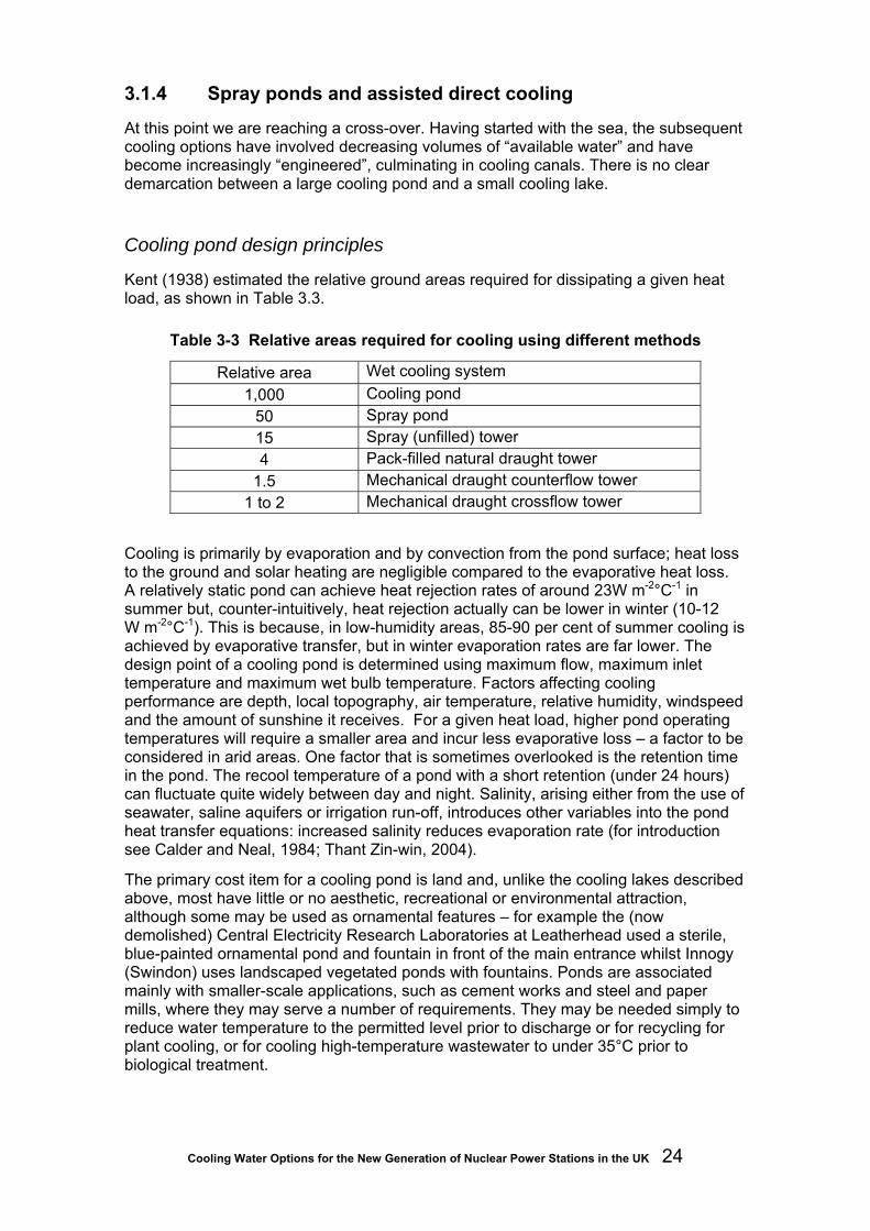
Cooling Water Options for the New Generation of Nuclear Power Stations in the UK 24
3.1.4 Spray ponds and assisted direct cooling
At this point we are reaching a cross-over. Having started with the sea, the subsequent cooling options have involved decreasing volumes of “available water” and have become increasingly “engineered”, culminating in cooling canals. There is no clear demarcation between a large cooling pond and a small cooling lake.
Cooling pond design principles
Kent (1938) estimated the relative ground areas required for dissipating a given heat load, as shown in Table 3.3.
Table 3-3 Relative areas required for cooling using different methods
Relative area Wet cooling system 1,000 Cooling pond
50 Spray pond 15 Spray (unfilled) tower 4 Pack-filled natural draught tower
1.5 Mechanical draught counterflow tower 1 to 2 Mechanical draught crossflow tower
Cooling is primarily by evaporation and by convection from the pond surface; heat loss to the ground and solar heating are negligible compared to the evaporative heat loss. A relatively static pond can achieve heat rejection rates of around 23W m-2°C-1 in summer but, counter-intuitively, heat rejection actually can be lower in winter (10-12 W m-2°C-1). This is because, in low-humidity areas, 85-90 per cent of summer cooling is achieved by evaporative transfer, but in winter evaporation rates are far lower. The design point of a cooling pond is determined using maximum flow, maximum inlet temperature and maximum wet bulb temperature. Factors affecting cooling performance are depth, local topography, air temperature, relative humidity, windspeed and the amount of sunshine it receives. For a given heat load, higher pond operating temperatures will require a smaller area and incur less evaporative loss – a factor to be considered in arid areas. One factor that is sometimes overlooked is the retention time in the pond. The recool temperature of a pond with a short retention (under 24 hours) can fluctuate quite widely between day and night. Salinity, arising either from the use of seawater, saline aquifers or irrigation run-off, introduces other variables into the pond heat transfer equations: increased salinity reduces evaporation rate (for introduction see Calder and Neal, 1984; Thant Zin-win, 2004).
The primary cost item for a cooling pond is land and, unlike the cooling lakes described above, most have little or no aesthetic, recreational or environmental attraction, although some may be used as ornamental features – for example the (now demolished) Central Electricity Research Laboratories at Leatherhead used a sterile, blue-painted ornamental pond and fountain in front of the main entrance whilst Innogy (Swindon) uses landscaped vegetated ponds with fountains. Ponds are associated mainly with smaller-scale applications, such as cement works and steel and paper mills, where they may serve a number of requirements. They may be needed simply to reduce water temperature to the permitted level prior to discharge or for recycling for plant cooling, or for cooling high-temperature wastewater to under 35°C prior to biological treatment.

Cooling Water Options for the New Generation of Nuclear Power Stations in the UK 25
In some cases the pond itself has a purifying (water treatment) function, especially if aerated. As with lakes, pond inflow may be directed by bunds or partitions to maximise the cooling path.
The design point of a cooling pond is determined using maximum flow, maximum inlet temperature and maximum wet bulb temperature. A system that performs under these conditions needs no assistance but borderline cases can be improved by enhancing air/water contact by aerating (stirring) the surface or by using pumped sprays. If only a small, or occasional, cooling improvement is needed, a floating agitator/aerator could suffice. The capital cost of a spray cooler is about five times that of an aerator of the same horsepower but, in similar climatic conditions, has a heat dissipation rate some 10 times greater. This can cool to within 9-10°F (5.5°C) of wet bulb temperature. Sprays also enable the pond area to be reduced, since a pond equipped with spray coolers needs only five per cent of the area of a simple pond. Factors affecting spray cooling efficiency include surface area of the spray, relative velocities of air and water during contact, and time for which droplets are in the air (Titchenor, 1971). A spray cooling pond occupies 10-20 times more land than a wet cooling tower. However its capital costs are far lower, especially when uprating an existing static pond, which can be done using an off-the-shelf package of floating platform with pumps and multiple nozzle assembly. For large-scale applications, such as for the proposed 1970s Bradwell demonstration commercial high-temperature reactor, several hectares of seawater ponds with fixed spray heads were planned. The excavation spoil was to be used for site-raising.
Figure 3-3 Spray cooling (photo courtesy Siemens Power Generation)

Cooling Water Options for the New Generation of Nuclear Power Stations in the UK 26
3.1.5 Tower cooling - general issues
Tower cooling continues the progression towards more complex engineered structures and reduced water requirement. In wet towers, the air/water contact is enhanced by enclosing and directing the air flow and by maximising air/water contact by exposing the water as droplets (as in spray ponds) or as a thin trickling film. The pond beneath a wet tower serves to collect the falling water and its area is no more than the basal area of the tower. Cooling is by direct transfer of heat to air and by evaporation of some of the water. Evaporating one kg of water removes sufficient heat to cool 100 kg through 10°C; thus, as a minimum a wet tower station need abstract only one per cent of its circulating volume. In practice about three per cent is usually abstracted, of which one per cent is evaporative loss (consumption) and the other two per cent is discharged (purged) back to the waterway to control the build-up of dissolved and suspended solids. The trend of less water consumption continues via hybrid wet and dry systems, where the evaporative-cooling component is reduced, to dry towers where the condenser cooling water is in finned tubes and does not come into direct contact with air and thus neither benefits from, nor loses water to, evaporation. Ultimately, no cooling water is involved at all and the steam exiting the turbine is condensed in large air-cooled radiators.
For many years cooling towers were used only where insufficient water was available or readily accessible for direct cooling. In some cases this was seasonal and the towers were brought into use only in summer. However, tower cooling also permits more flexible siting, which can reduce fuel transport and/or transmission costs. Against this is the higher capital cost of towers, although these costs might be marginal when set against emplacing or tunnelling large diameter pipes for direct cooling. Towers, and particularly dry towers, have lower thermal efficiency because of the higher cooling water temperatures at the condenser inlet; this can reduce the station’s efficiency by three to five per cent compared with direct cooling. The economics are not entirely negative, since with higher backpressure the dimensions of the turbine LP cylinders can be reduced, with fewer and smaller diameter discs and a corresponding reduction in the dimensions of the casing and exhaust steam passages. These economic arguments need to be weighed in each case. Furthermore, in the USA and in Europe, tower cooling is increasingly required for environmental reasons since less water is abstracted and less heat is discharged to the receiving waterway. It is for this reason that wet cooling towers, and even air-cooled towers and condensers, are being built in coastal locations. Many of the problems associated with cooling towers (chemical scaling, sliming and siltation) apply equally to fresh and salt water. Corrosion is more of a problem in saltwater towers and, whilst salt (NaCl) drift is unique to them, dissolved solids drift is an issue for any tower operating at high concentration factor (CF).
3.1.6 Tower components and terminology
Splash pack
Splash pack consists of tiers of horizontal, triangular-section, wooden or plastic slats wetted by droplets that form and reform as they shower down through them. Wooden laths, and other timber-supporting structures in the tower, have to be impregnated with chemicals (typically arsenic, chromium and copper mixtures) to prevent fungal rot and, in saline towers such as Connahs Quay A and Fleetwood, attack by burrowing gribble (the shrimp-like Limnoria). Chlorination and alkaline conditions can accelerate de-lignification, weakening the timber. Build-up of slimes, scale and silt on splash pack
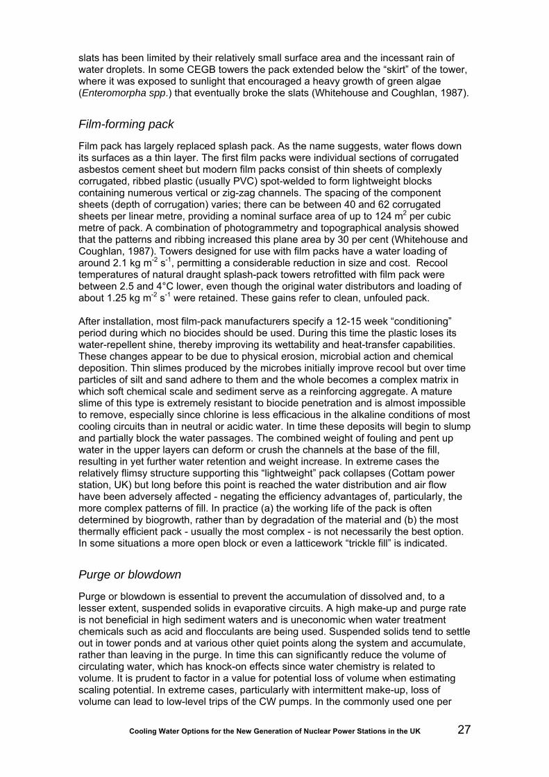
Cooling Water Options for the New Generation of Nuclear Power Stations in the UK 27
slats has been limited by their relatively small surface area and the incessant rain of water droplets. In some CEGB towers the pack extended below the “skirt” of the tower, where it was exposed to sunlight that encouraged a heavy growth of green algae (Enteromorpha spp.) that eventually broke the slats (Whitehouse and Coughlan, 1987).
Film-forming pack
Film pack has largely replaced splash pack. As the name suggests, water flows down its surfaces as a thin layer. The first film packs were individual sections of corrugated asbestos cement sheet but modern film packs consist of thin sheets of complexly corrugated, ribbed plastic (usually PVC) spot-welded to form lightweight blocks containing numerous vertical or zig-zag channels. The spacing of the component sheets (depth of corrugation) varies; there can be between 40 and 62 corrugated sheets per linear metre, providing a nominal surface area of up to 124 m2 per cubic metre of pack. A combination of photogrammetry and topographical analysis showed that the patterns and ribbing increased this plane area by 30 per cent (Whitehouse and Coughlan, 1987). Towers designed for use with film packs have a water loading of around 2.1 kg m-2 s-1, permitting a considerable reduction in size and cost. Recool temperatures of natural draught splash-pack towers retrofitted with film pack were between 2.5 and 4°C lower, even though the original water distributors and loading of about 1.25 kg m-2 s-1 were retained. These gains refer to clean, unfouled pack. After installation, most film-pack manufacturers specify a 12-15 week “conditioning” period during which no biocides should be used. During this time the plastic loses its water-repellent shine, thereby improving its wettability and heat-transfer capabilities. These changes appear to be due to physical erosion, microbial action and chemical deposition. Thin slimes produced by the microbes initially improve recool but over time particles of silt and sand adhere to them and the whole becomes a complex matrix in which soft chemical scale and sediment serve as a reinforcing aggregate. A mature slime of this type is extremely resistant to biocide penetration and is almost impossible to remove, especially since chlorine is less efficacious in the alkaline conditions of most cooling circuits than in neutral or acidic water. In time these deposits will begin to slump and partially block the water passages. The combined weight of fouling and pent up water in the upper layers can deform or crush the channels at the base of the fill, resulting in yet further water retention and weight increase. In extreme cases the relatively flimsy structure supporting this “lightweight” pack collapses (Cottam power station, UK) but long before this point is reached the water distribution and air flow have been adversely affected - negating the efficiency advantages of, particularly, the more complex patterns of fill. In practice (a) the working life of the pack is often determined by biogrowth, rather than by degradation of the material and (b) the most thermally efficient pack - usually the most complex - is not necessarily the best option. In some situations a more open block or even a latticework “trickle fill” is indicated.
Purge or blowdown
Purge or blowdown is essential to prevent the accumulation of dissolved and, to a lesser extent, suspended solids in evaporative circuits. A high make-up and purge rate is not beneficial in high sediment waters and is uneconomic when water treatment chemicals such as acid and flocculants are being used. Suspended solids tend to settle out in tower ponds and at various other quiet points along the system and accumulate, rather than leaving in the purge. In time this can significantly reduce the volume of circulating water, which has knock-on effects since water chemistry is related to volume. It is prudent to factor in a value for potential loss of volume when estimating scaling potential. In extreme cases, particularly with intermittent make-up, loss of volume can lead to low-level trips of the CW pumps. In the commonly used one per

Cooling Water Options for the New Generation of Nuclear Power Stations in the UK 28
cent evaporation/two per cent purge/three per cent make-up circuit, the concentration factor (CF) is 1.5 and a “particle” of water would, on average, go round the circuit 23 times before half of it had been either evaporated or purged (Table 3-4). This is sometimes referred to in terms of retention time; however, with continuous purge a fraction of the make-up will leave the system on its first circuit whilst some will still be in the system many months later. Make-up and purge both may be continuous or discontinuous. Discontinuous purge enables intermittently applied water treatment chemicals such as chlorine to be retained in circuit until they have decayed to a level suitable for discharge or until, for example, tidal conditions are suitable. Where temperature consents permit, it is thermally beneficial to purge water before it has been through a cooling tower.
Table 3-4 Relationship between concentration factor, half-life (retention) and make-up rate, assuming one per cent evaporative loss of the circulating volume
Make-up volume (%)
Purge volume (%)
Concentration factor Half-life (cycles)
5 4 1.25 13.5 4 3 1.33 17 3 2 1.5 23 2 1 2 34
1.5 0.5 3 46 1 0.2 6 58
There are situations where even three per cent of the circulating volume exceeds the supply of water available. In such situations the CF must be increased; some stations in arid zones work on zero purge. High CFs and especially zero purge create difficulties with the chemical management of the circuit and continuous treatment is required to reduce the dissolved solids content to prevent heavy scaling in condensers and coolers. Cooling towers are very effective at scrubbing CO2 from the circulating water, thereby raising the pH. This is usually redressed by adding acid16 to keep the carbonate equilibrium on the (soluble) bicarbonate side, but can also be achieved by CO2 injection, using scrubbed flue-gas. By coincidence, the use of treated sewage effluent as make-up reduces the need for acid since oxidation of ammonia yields nitric acid. An alternative approach to scale control is to soften all the incoming make-up water (as tried at Little Barford) or to continuously treat a fraction of the circulating water (side stream treatment). The sludge resulting from water treatment is almost impossible to dewater and typically is lagooned. A review of power requirements in the western United States concluded that most new build will be on inland sites. Here, they will be competing with agriculture and public users for water and will need to go down the high CF tower route. Environmental legislation will constrain them to dispose of the sludge in lined evaporation ponds (Jury et al. 1980).
Carryover or drift
Cooling water droplets of varying sizes are entrained in the rush of air emerging from the top of the pack but the majority of these should be removed by impingement against the “eliminators” where the air flow is forced to change direction rapidly (the same principle as in steam moisture removers). Not all droplets that have passed through the eliminators as carryover will leave the tower. Condensation can occur above the eliminators in tall natural draught towers and condensate and carryover 16 UK stations tend to use sulphuric acid. This is more expensive than hydrochloric acid but is easier to handle since it does not fume in moist air.

Cooling Water Options for the New Generation of Nuclear Power Stations in the UK 29
droplets swirl around inside the tower (“uprain” and “downrain”) growing in size through collisions and further condensation. Some droplets will be expelled from the top of the tower in the updraught but others become so large that they fall back onto the eliminators and drip back onto the pack. Much of the potential carryover is removed by this process. Mechanical draught towers are shorter and far less prone to internal condensation, and hence more likely to expel all carryover. Manufacturers usually specify a performance value for such non-evaporative losses but experience has shown that it is near-impossible to discriminate between carryover (drift), washout and leaks.
Washout or blowout
Water falling from the base of the pack into the pond may be blown out of the tower by crosswinds. Washout comprises droplets of “raw” cooling water and as such will carry dissolved and suspended solids and possibly pathogens. The concentration of suspended solids may be augmented by fouling washed out of the tower pack. Drift is mainly a problem with natural draught towers since these have a large unrestricted air gap below the shell through which falls a constant rain. On induced draught mechanical towers this gap is usually fitted with louvres to minimise through-wind, whilst on forced draught towers there is no gap since the fan is at the air entry. Typical drift values for natural draught towers are 0.3-1.0 per cent of the circulating rate and 0.1-0.3 per cent for mechanical draught towers although some manufacturers claim drift rates as low as 0.02 per cent and even 0.005 per cent if sufficient attention is paid to design and maintenance. With seawater towers, salt drift is of particular concern.
3.1.7 Wet towers
Configuration
There are three basic air/water combinations for both natural draught and mechanical wet towers. In co-current towers the air flow is downward, having been entrained by the descending water. In counterflow (countercurrent) towers the air moves upwards through the descending water. In crossflow towers the air moves laterally through the descending water. Co-current towers, also known as spray towers, are relatively short, have no moving parts and are the least efficient. Counterflow provides a more efficient heat transfer than crossflow, since the coolest water contacts the coolest air, but the towers are relatively taller with higher pumping costs. The water may fall freely as droplets (spray towers) but it is more usual to have some type of fill or pack to prolong the air/water contact time and to increase the area of the water surface, thereby improving the recool temperature. The warm water is distributed across the top of the pack by pans, channels or pipes fitted with nozzles or splash-type spray heads. For maximum efficiency there should be an even water loading and air flow across the entire pack. In circular-section natural draught towers, air flow tends to decrease at the centre but this can be countered by increasing the depth of pack around the edge.
Design principles
The key factors in tower design are the maximum water loading (inflow volume) and temperature, the air:water ratio and the wet bulb temperature. A close approach to wet bulb temperature (high temperature range) requires a large air:water ratio but, since airflow is the main determinant of tower size and cost, it cannot be increased economically beyond certain limits. The opposite strategy is to opt for a smaller, shorter

Cooling Water Options for the New Generation of Nuclear Power Stations in the UK 30
tower with a small air:water ratio, a large approach and small range. Most design requirements fall somewhere between these extremes. Performance indicators and coefficients can indicate how close a particular tower comes to an ideal case but, in practice, such indicators are often meaningless since the most efficient tower is simply the one giving the best overall economy in its situation. To ensure consistent, adequate performance, a “worst case” wet bulb temperature (say one that would not be exceeded for more than one per cent of the time during the summer) is selected, based on historic data. Over the years, power plant cooling towers have been designed with approaches ranging from 5 to 12 °F (2.8°C to 6.7°C). Cooling to within 5°F of wet bulb temperature would give optimal performance but 8°F (4.5°C) is more typical.
Natural draught towers
In a natural draught tower, the tower shell (typically a hyperbolic profile concrete structure) extends high above the wet section and functions as a chimney, with the convective rise of warmed air drawing in cooler air at the tower base. Obviously this convective air flow will stop should the air temperature (dry bulb) exceed the temperature of the inlet water. However the tower does not cease to cool efficiently if the wet bulb temperature exceeds inlet water temperature. This is because the air is warmed as it enters the tower, thereby raising its wet bulb temperature. These towers do not require fans and have low operating costs but can incur maintenance costs. Moreover there is little if any scope for control and this often results in overcooling. The 1,000 MWe Ince B (UK) station was cooled by a large, fan-assisted natural draught tower. Previously a station of this size would have used four unassisted towers.
Mechanical draught towers
Mechanical draught towers, usually constructed of timber or plastic, are totally reliant on large axial flow fans to push or pull air through the pack, which gives a more consistent air flow than in natural draught towers. By using internal doors and variable speed or variable pitch fans, the performance of such towers can be matched to prevailing atmospheric conditions. In central and western USA, such towers are used exclusively since they can provide a more controlled performance in conditions ranging from freezing to hot and dry. In most situations, they provide lower recool temperatures than natural draught towers but their power consumption is typically about 0.5 per cent of the plant's output. Towers with the fan at the discharge (induced draught) have a low air entrance velocity but a high exit velocity that reduces the possibility of recirculating saturated discharged air back into the air intake. Forced draught towers, with the fan at the intake, have high entrance but low exit air velocities. The low exit velocity is much more prone to recirculation and icing. Teesside CCGT co-generation power station has a single hyperbolic tower with 22 fans around its base, giving an air flow of almost 10,500 kg s-1 and a water loading of 8,000 kg s-1, to provide a cooling capacity of about 460 MWth. Depending on load and ambient conditions the inlet temperature averages 30°C with a 16.5°C recool. The station has two back-up forced draught hybrid towers to bring into use when the thermal export demand is reduced.
Hybrid tower systems
Many types of tower, or combinations of towers, can be described as “hybrid”. Their common feature is that they all are used to cool water that has been used in a surface condenser.

Cooling Water Options for the New Generation of Nuclear Power Stations in the UK 31
(a) A natural draught tower augmented by fans at its base has a greater cooling capacity than a natural draught tower of similar size, and the fans can be used in response to load or season.
(b) A hybrid mechanical draught tower incorporates a “dry” (radiant) section above the wet pack. A proportion, or all, of the incoming water is routed through finned tubes in the dry section (sensible/dry bulb approach) before it is sprayed over the pack in the wet section (latent/wet bulb approach). In some cases this arrangement is adopted for “plume abatement”; one disadvantage of low profile mechanical draught towers is that any plume of vapour or drizzle is far closer to the ground than with a natural draught tower and this can cause ground fog and icing on nearby roads. The warm air coming through from the dry section mixes with the saturated air rising from the wet section, raising its dew point and giving added buoyancy to the plume. In some climates the tower can operate for much of the year using the dry section alone, greatly reducing annual water consumption.
(c) Hybrid pack is a type of plastic fill used in crossflow towers. Air flows through horizontal channels (pipes) in the matrix whilst water percolates over them, without direct contact. In an alternative design the wet and dry channels are inclined at 45° to the vertical. The aim is to create an extensive area of air-cooled surface over which the water flows in a thin film, with minimal evaporative loss. Both types of fill were trialled for Deeside CCGT (Coughlan, 1972) but were not installed owing to their high propensity for fouling. Salt and/or scale deposits can become a problem at the front face of some crossflow film packs. On the Deeside test-rig, seepage from the wet channels or recirculating spray intermittently wetted the front face. This rapidly dried, given the combination of a flow of dry air and warm pack, leaving encrusting deposits that accumulated and progressively restricted the air flow. The Rechem chemical plant (Fawley) had a freshwater tower fitted with this same pack and experienced a similar build-up of scale on the front face that was attributed wholly to seepage.
(d) Hybrid wet and dry cooling systems are an attempt to gain the advantages of both whilst offsetting the disadvantages of each – high water consumption and poor recool, respectively. They are essentially an extension of (b) above but use separate wet and dry towers (see Section 3.1.8). If designed for maximum water conservation, the design point is essentially an all-dry system with just enough wet capacity to prevent significant deterioration in recool during the hottest weather. This is sometimes referred to as a dry/wet peaking tower system. Alternatively the dry system could be used to improve the recool of a wet tower, either in parallel or series. In parallel cooling, some of the water from the inflow to the wet tower is diverted to the dry tower. This reduces the water loading on the wet tower, raises its air:water ratio and produces a lower recool temperature. The water leaving the dry unit is not as cold, but when mixed with the water in the tower pond, causes only a slight temperature increase. In series cooling, the water leaving the dry unit is fed back into the wet unit’s inflow to reduce the tower inlet temperature, again with improved recool temperature. No working examples of these arrangements were identified. An Australian desk study (Williams, 2007) concluded that the additional power costs for pumps and fans on the dry unit would render retrofitting uneconomic.
(e) Helper or auxiliary towers are sometimes used to augment or completely replace the cooling function of a direct system during times of low river flow (Willington A) or when river temperature exceeds some preset value. Barking (lower Thames) is normally direct cooled but can switch to mechanical draught wet towers in summer; Didcot A (non-tidal Thames) has a stepped consent relating to river flow and temperature and, as a first step, uses a mechanical draught wet tower to cool the purge from its natural draught towers. The direct-cooled Brayton Point MA USA station, under pressure over fish protection and thermal discharge issues, plans to retrofit towers to

Cooling Water Options for the New Generation of Nuclear Power Stations in the UK 32
cool 1,100 MWe of its plant, with the ability to use them as helper towers for the remaining 500 MWe.
3.1.8 Parallel Condensing System TM (PAC)
PAC is a patented GEA Group concept in which the exhaust steam from the turbine is split into two, variable, streams. One goes to a water-cooled surface condenser (with a wet-tower) and the other to an air-cooled condenser (See Section 3.1.10 below). Unlike the hybrid wet/dry towers described above, the dry unit of a PAC system is a condenser. Even on hot days the dry section can reject a substantial amount of heat, thereby reducing peak water usage. During the cooler months, if so designed, the heat rejected by the dry unit can be increased up to 100 per cent, with no evaporative losses. The plume can be reduced or eliminated entirely when danger of icing exists, simply by shutting down the wet section.
3.1.9 Dry towers (indirect dry cooling, fin-fan cooling)
Conventional surface condenser
The cooling circuit layout is the same as for a recirculating wet tower system except that when the water reaches the tower it does not come into contact with air but passes through finned tubes that are cooled by air flowing past them. There is no evaporative cooling, and hence no loss of cooling water, but the heat transfer to air via metal fins is much less efficient. The technology for small cooling applications is well established and usually comprises an elevated, horizontal cooling matrix with a horizontal fan beneath it. Duty can be increased by adding more modules. The largest installation is ESKOM’s 4,500 MWe Kendal plant (South Africa). The 20 m3s-1 CW flow from the condensers of each 686 MWe turbine passes through radially arranged, horizontal, heat exchangers (HEs) lying above the air inlet in one of six 165 m tall natural draught towers. The total length of finned, elliptical section, galvanised tube in each tower is 1,980 km, arranged in eleven isolatable sectors. The auxiliary power consumption/unit (additional pumps) is 3.4 MW (Du Preez, 2008). After 20 years operation the towers still match design performance and there has been no corrosion on the HEs.
Spray, jet or barometric condenser (or Heller system)
Spray condensers need no cooling water and no tubes. A fraction of the condensate is taken from the hotwell at the base of the condenser, cooled – usually with a natural draught dry cooling tower - and then sprayed back into the condenser to continue the condensation process. In 1961 a hyperbolic natural draught tower with vertical heat exchange matrices (radiators) around the air inlet was built at Rugeley A (UK) for a 192 MWe unit. The radiators were high purity aluminium to avoid internal corrosion and contamination of the circulating boiler feed water, (condensate) but the risk of external corrosion had been underestimated. Although the chloride content of the atmosphere was low, it became concentrated in crevices by evaporation and eventually caused corrosion and leaks. Several matrices were split by freezing. Since that time many systems have been built and operated successfully in Europe and worldwide.

Cooling Water Options for the New Generation of Nuclear Power Stations in the UK 33
3.1.10 Wet surface air coolers (closed-loop evaporative cooling, WSAC)
Dry coolers are totally reliant on sensible heat transfer (radiation) to air. Since air has a low heat capacity and the approach is restricted to dry bulb (air) temperature, the recool is always higher than for an equivalent wet cooling system.
Table 3-5 Economics of four methods of evaporative enhancement of dry coolers (adapted from Kutscher and Costenaro, 2002)
Direct water
contact Up-front air cooling
Deluge over
HE tubes (WSAC)
Coarse spray and wet
eliminator pack
Fine spray misting system
Air drawn through wet
pack Total capital cost (ratio)
$37,139 (1.0)
$134,911 (3.6)
$155,977 (4.2)
$184,530 (5.0)
Additional cost /MW gain/year
$ 19 $ 34 $ 47 $ 60
Simple payback years
1 4 5 7
Internal rate of return %
165 32 23 16
Wet surface air coolers (WSAC) resemble conventional dry coolers in that the fluid to be cooled or condensed (see Section 3.1.11) is retained in a closed loop. However at the HE, water is cascaded over the cooler surface. Evaporation, aided by air draught, cools the HE tube surface and permits approach to within 5 to 10°F (2.8 to 5.5°C) of wet bulb temperature. Hauser (1982) estimated that wetting a “dry” HE increased its heat transfer three- to seven-fold. There are several interesting features in this approach (ref: Niagara Blower Company). WSAC has a far smaller footprint than an air-cooler, it consumes about 60 per cent less energy and delivers better recool. For example, on a 38°C dry bulb/24°C wet bulb day, the recool temperature of a dry cooler will be around 52°C when a WSAC could easily deliver 32°C. The water spray on the Niagara Blowers system is large volume/low pressure, typically delivering 4-7 l s-1 m-2 on to the HE surface, in the same direction (co-current) as the fan-induced air flow. Consequently the sprays are accessible for inspection and maintenance. Excess water falls into the tower basin and air-borne droplets are separated and recovered as the air enters the fan plenum chamber. Make-up water can come from almost any source and can be used at high CFs since there is little potential for fouling as the HE tubes are not finned. Kutscher and Costenaro (2002) evaluated the benefits of four methods of evaporative enhancement of small dry cooling systems (Table 3-5). One was by WSAC deluge and the other three involved cooling the air upstream of the HE. The main advantage of the cooled-air system was that it avoided direct water contact with finned tubes; a problem that Niagara Blower avoids by using plain tube that, incidentally can be of almost any material and pressure rating. We could not find any example of WASC use on a large cooling circuit.

Cooling Water Options for the New Generation of Nuclear Power Stations in the UK 34
3.1.11 Air-cooled condensers (ACCs, direct dry cooling)
The indirect dry-cooled plant (Section 2.4.5) condensed steam in a standard surface (shell and tube) condenser and the cooling water was then circulated through a dry cooling tower. Direct dry cooling dispenses with the water loop and steam is exhausted directly to the cooler. However, the structures are necessarily large since the density of air is 830 times less than that of water and its thermal capacity is 75 per cent less. Thus Rye House (ref. Rye House), a UK CCGT station with an air-cooled condenser (250 MWe), has 600 A-frame radiator units mounted 24 m above the ground with 100 fans (6.1 m diameter, 68 rpm) below them. The radiators comprise 60,000 sections of oval finned tube, totalling more than 160 km in length.
No figures are available for Rye House but a 270 MWe steam turbine with a similarly sized ACC at Damhead Creek (Kent) has a design backpressure of 84 mbar that can rise to 150 mbar in adverse weather conditions, compared with a fairly constant 40 mbar for a typical water-cooled condenser (Turnpenny and Coughlan, 2003). Adverse conditions include high winds and gusts that can stall the fans, and little or no wind that can allow warm air to recycle. Overall, the efficiency of an ACC station is likely to be two per cent lower than a direct, water-cooled one. This equates to a loss of electrical output of at least 2.5 per cent, rising to four per cent (BREF/IPPC, 2000). On the other hand there is no evaporative consumption, abstraction or discharge of cooling water.
The largest ACCs are at ESKOM’s 3,990 MWe Matimba plant (ref. GEA) with 48, 10 m diameter fans with a power consumption of 12 MW. Matimba has an average backpressure of 186 mbar with LP turbine protection at 650 mbar.
The external surfaces of ACC finned tubes are prone to fouling from pollen, dust, insects, leaves, plastic bags, bird and bat carcasses and so on, reducing airflow, heat transfer and performance and increasing operating costs. In severe cases, fouling can limit the power generation capacity (capability). Automatic washing/brushing equipment is often fitted (ref ConCo Services). Other problems include inward air leaks (the HEs are under vacuum) and freezing of the condensate. Aircraft engines, air-cooling systems and gas turbines all draw in large volumes of air and will catch insects and birds. The authors are not aware of any published literature quantifying this impact, but the parallels to aquatic impingement and entrainment are obvious (Veil et al. 2001).
Even in the UK, climatic conditions are such that several CCGTs with air-cooled auxiliary coolers have experienced operational problems during summer, despite their air-cooled condensers operating successfully. Rye House CCGT has an air-cooled condenser but uses wet towers to support critical functions such as cooling lubricating oil. Inadequate recool results in decreased viscosity and high turbo-alternator journal and thrust bearing temperatures and Paton et al. (2005) report that a few degrees change in oil temperature can alter the dynamic behaviour of the turbine shaft.
A recent study of the environmental impacts of wet and dry cooling (USEPA, 2000) concluded that energy consumption, per kg of condensate, was higher for dry cooling than for wet cooling and that the atmospheric emissions associated with that energy consumption also were higher. The energy penalty increases with the ambient air temperature. These disadvantages are offset by water demand being reduced by four to seven per cent compared with a recirculating system and 99 per cent over that required by a once-through system17. Dry cooling eliminates visual plumes, fog, mineral (salt) drift, cooling water treatment chemicals and several waste disposal issues. Nevertheless the study concludes that “dry cooling does not represent the “best
17 Water demand here encompasses consumptive and non-consumptive uses and these may be derived from different sources. The one per cent remaining for the direct-cooled station would be for boiler feed and domestic use.

Cooling Water Options for the New Generation of Nuclear Power Stations in the UK 35
technology available (BTA)” for minimizing environmental impact” and EPA is concerned that “the high costs and energy penalty of dry cooling systems may remove the incentive for replacing older coal-fired plants” although this should not prevent ACCs being selected where there is no practical alternative. Sometimes wet towers, air cooling or ACCs may be built simply to forestall lengthy planning delays and environmental objections. One notable example is Mystic Harbour MA (EPRI, 2007), built on the edge of Boston Harbour. Air-cooled plants often use wet cooling for some auxiliary cooling purposes. Auxiliaries are air cooled at Crocket.
3.2 Issues on the use of seawater in cooling towers
3.2.1 Tower sizing
Water having more than 750 mg l-1 chloride (as NaCl) is considered saline, although full-strength seawater contains 26,000 mg l-1 NaCl and 30 to 34,000 mg l-1 total dissolved solids (3 to 3.4 per cent). With CF 1.3 to 1.5, the dissolved solids in the circulating water could reach five per cent or 50,000 mg l-1. Seawater circuits seldom go above CF2, but some high CF arid-zone saline circuits will do so. At even 5,000 mg l-1 parameters such as specific gravity, boiling point/partial pressure and specific heat diverge significantly from freshwater values and must be allowed for in the design point calculations (see Maulbetsch & DiFilippo, 2008). Salinity increases specific gravity but, in thermal performance, the reduction in vapour pressure and specific heat (thermal capacity) outweighs this, so a saltwater tower must have a higher water flow or wider range to handle the same heat load. The thermal performance of a typical mechanical draught cooling tower could decrease by two to five per cent when operating at 50,000 mg l-1 dissolved solids. Operating at a lower CF would limit the build-up of dissolved solids, but at the risk of increasing the rate at which suspended solids are imported.
3.2.2 Scaling, corrosion and abrasion
Scaling and corrosion, often regarded as two sides of the same coin, must be considered at every stage of design for seawater circuits. The widely used Langelier Saturation Index is a useful indicator of carbonate scale formation but it is purely an equilibrium index and gives no indication of how much scale will form, or calcium carbonate will precipitate, in bringing the water to equilibrium. Scaling and corrosion are influenced by pH, hardness, alkalinity, total dissolved solids and temperature so in theory an equilibrium condition can be maintained so that neither occurs. However this tends to ignore the dynamics of the system. Seawater is naturally around pH 8 and is well buffered; this pH is outside the range 6-7 normally recommended for minimising scaling and corrosion. With low CF operation (relatively high purge flows) it is uneconomic and environmentally unacceptable to rely on dosing scale and corrosion inhibitors. Low volume circuits, where the aim is maintain high water velocities to keep silt and fine sand on the move, if not permanently in suspension, can abrade components and increase corrosion rates by scouring away potentially protective films.
3.2.3 Material selection
The principles for selecting and mixing component materials for use in seawater are fairly well understood. However, with tower cooling circuits and within the towers themselves, conditions are more extreme than those encountered routinely, since the

Cooling Water Options for the New Generation of Nuclear Power Stations in the UK 36
temperature and salt concentration are elevated and the water can be supersaturated with air. It is a fact that corrosion proceeds most rapidly at an air/water interface (typically at the waterline) and in damp well-aerated conditions. In and around towers, alternate drying and wetting will first concentrate salts on a surface and then wash away potentially protective corrosion products (see Maulbetsch & DiFilippo, 2008).
For the tower ponds, and any internal structures to be fabricated in reinforced concrete, a minimal-water mix and the replacement of a proportion of the cement with 30 per cent pulverised fuel ash (PFA) or 60 per cent ground granulated blast furnace slag (GGBS) has been recommended. This reduces chloride diffusion in water temperatures up to 30° and 40° C respectively. The rebars themselves may be epoxy-coated but at minimum the bars should not be salt-contaminated from the atmosphere prior to placement. Steel should be avoided but pressure-treated timbers such as California redwood and Douglas fir are durable and there is no difference in their lifetime performance between seawater and freshwater towers. Controlled conditions and extreme care must be taken when applying coatings to steel or concrete on site. Coatings should be regarded as unreliable and best avoided if alternative corrosion-resistant materials are available. Medium-density polyethylene (MDPE) and glass-reinforced plastic (GRP) pipes and sections are preferable to coated steel. Even small items such as nuts, bolts and rivets may be subject to attack
The care taken in selecting materials for major items often does not extend to minor items. Thus at National Power’s Killingholme CCGT (estuarine) the cooling towers’ wooden internals had to be refixed within five years, replacing all the bronze fittings and hardware with a chromium/molybdenum steel (Xeron-100). Aluminium and silicon bronzes do not perform well in oxygenated saline waters. In particular silicon bronzes have poor resistance to erosion/corrosion, as caused by the impact of falling droplets, on the heads and nuts of through-bolts. They are also attacked by chlorine, particularly above 0.5 mgl-1. With this experience National Power insisted on Xeron-100 (cheaper Xeron-25 was not suitable) for the towers at Deeside CCGT (estuarine, commissioned around1994). These towers had an upper dry section for plume abatement that used 90:10 Cu:Ni tube, a relatively cheap material. However, these tubes suffered rapid and severe internal erosion/corrosion and were soon replaced by titanium, which would have seemed the logical initial choice since titanium tube had been specified for the condensers. PowerGen’s Connahs Quay plant, across the river from Deeside, uses the same Cu:Ni tubes in its dry sections but has experienced no problems. This suggests that factors other than water chemistry were involved and it is possible that sand scour was responsible for the severity of the damage at Deeside.
3.2.4 Purge (blowdown)
Purge or blowdown from a saline tower necessarily has a higher concentration of solids than the source water. On a seawater system, where there should be no shortage of make-up water, purge is unlikely to exceed double strength and, given the relatively small volume, it should not pose any regulatory problem other than the usual concerns over biocides.
3.2.5 Salt carryover
The plume emerging from the top of a tower should be almost pure condensate and as such carry virtually no salt if the eliminators are of good design, are all in place and the air and water loadings are correct. This situation can change rapidly should the water distribution alter as a result of blocked distributors or there is distorted or displaced pack. If a pack section is missing, the increased updraught can dislodge the eliminators

Cooling Water Options for the New Generation of Nuclear Power Stations in the UK 37
enabling significant carryover of droplets. However, the main causes of damage to eliminators were attributed to careless handling and/or refitting following water-distributor maintenance. It is difficult to measure how much water is being lost as carryover and so it is generally included with drift loss, that is, all cooling water loss other than by evaporation. Since the total loss includes leakage and the evaporative loss itself is obtained by calculation from the cooling duty, any estimate of carryover is prone to considerable error. Carryover, especially from natural draught towers, is ejected at high level and as the droplets are carried away from the tower they diminish in size by evaporation and become less liable to reach the ground before they have become widely dispersed.
3.2.6 Salt water washout
Drift is water that is blown sideways from the base of cooling towers. This is a particular feature of natural draught towers that have a large gap (air entry), but can also affect mechanical draught towers in strong crosswinds or if the louvres are inadequate. Drift is mainly relatively large droplets and, starting near ground level, seldom spreads far off site. Effects on the cladding and structure of buildings, transformers and switchgear, gas turbine air intakes and even landscape planting should be considered at the design stage. Marley (1986) recommends that even though low levels of drift are attainable – under 0.005 per cent is cited - a saltwater cooling tower should never be sited near sensitive equipment. Apart from dissolved salts, these drops will also contain silt particles carried by the circulating water, possibly augmented by solids washed off the tower pack. The environmental aspects of salt drift and carryover are considered in Section 6.2.1.
3.2.7 Sedimentation
This problem is generally no greater at coastal sites than at many lowland river sites; in fact, marine sediments are often coarser than river sediments and are more easily removed from the incoming water. If left, coarse and fine sand will almost certainly drop out in the circuit. At Deeside CCGT, the turnkey contractor was unwilling to modify the design despite evidence of high concentrations of suspended sand. The contractor insisted that sedimentation would be controlled by maintaining high water velocities through the plant and having no pond (just a sloping tray) under the towers. Eventually the intake design was modified to provide a small, largely ineffectual, sand trap and, after numerous problems, hydrocyclones had to be installed at the intake. At Connah’s Quay, across the river from Deeside, the incoming water is pumped into a large settling basin with an automated sand-removal system. This problem would clearly be greater on macrotidal water such as the Severn Estuary/Bristol Channel, where suspended sediment concentrations may reach 5 g l-1.
3.2.8 Biofouling
There are two broad categories of biofouling - microbiofouling and macrobiofouling. The former comprise bacterial and fungal slimes that begin to develop on virtually any wetted surface - fresh or saltwater - within minutes of immersion. The most immediate effect of slimes is the reduction of heat transfer in condensers but they can also accelerate corrosion (microbiologically induced corrosion MIC) of metals and concrete. Condenser slimes never used to be a problem at seawater-cooled UK power stations and this was thought to be due to the surface toxicity of copper in the tube alloys, possibly aided by sand abrasion. The introduction of titanium tubes that lack inherent toxicity allowed slimes to develop, so most new stations specify a mechanical tube-
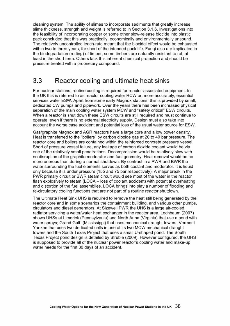
Cooling Water Options for the New Generation of Nuclear Power Stations in the UK 38
cleaning system. The ability of slimes to incorporate sediments that greatly increase slime thickness, strength and weight is referred to in Section 3.1.6. Investigations into the feasibility of incorporating copper or some other slow-release biocide into plastic pack concluded that this was practically, economically and environmentally unsound. The relatively uncontrolled leach-rate meant that the biocidal effect would be exhausted within two to three years, far short of the intended pack life. Fungi also are implicated in the biodegradation (rotting) of timber; some timbers are naturally resistant to rot, at least in the short term. Others lack this inherent chemical protection and should be pressure treated with a proprietary compound.
3.3 Reactor cooling and ultimate heat sinks For nuclear stations, routine cooling is required for reactor-associated equipment. In the UK this is referred to as reactor cooling water RCW or, more accurately, essential services water ESW. Apart from some early Magnox stations, this is provided by small, dedicated CW pumps and pipework. Over the years there has been increased physical separation of the main cooling water system MCW and “safety critical” ESW circuits. When a reactor is shut down these ESW circuits are still required and must continue to operate, even if there is no external electricity supply. Design must also take into account the worse case accident and potential loss of the usual water source for ESW.
Gas/graphite Magnox and AGR reactors have a large core and a low power density. Heat is transferred to the “boilers” by carbon dioxide gas at 20 to 40 bar pressure. The reactor core and boilers are contained within the reinforced concrete pressure vessel. Short of pressure vessel failure, any leakage of carbon dioxide coolant would be via one of the relatively small penetrations. Decompression would be relatively slow with no disruption of the graphite moderator and fuel geometry. Heat removal would be no more onerous than during a normal shutdown. By contrast in a PWR and BWR the water surrounding the fuel elements serves as both coolant and moderator. It is liquid only because it is under pressure (155 and 75 bar respectively). A major break in the PWR primary circuit or BWR steam circuit would see most of the water in the reactor flash explosively to steam (LOCA – loss of coolant accident) with potential overheating and distortion of the fuel assemblies. LOCA brings into play a number of flooding and re-circulatory cooling functions that are not part of a routine reactor shutdown.
The Ultimate Heat Sink UHS is required to remove the heat still being generated by the reactor core and in some scenarios the containment building, and various other pumps, circulators and diesel generators. At Sizewell PWR the UHS is a large air-cooled radiator servicing a water/water heat exchanger in the reactor area. Lochbaum (2007) shows UHSs at Limerick (Pennsylvania) and North Anna (Virginia) that use a pond with water sprays; Grand Gulf (Mississippi) that uses mechanical draught towers; Vermont Yankee that uses two dedicated cells in one of its two MCW mechanical draught towers and the South Texas Project that uses a small U-shaped pond. The South Texas Project pond design is detailed by Struble (2009). However configured, the UHS is supposed to provide all of the nuclear power reactor’s cooling water and make-up water needs for the first 30 days of an accident.

Cooling Water Options for the New Generation of Nuclear Power Stations in the UK 39
4 CW system design
4.1 Direct CW systems
4.1.1 System description
Direct CW systems usually require a coastal location. Figure 4-1 shows a schematic arrangement of a direct CW system with an inshore intake and an inshore outfall.
Figure 4-1 Diagram of typical direct CW system
The main components of the system are:
• intake structure;
• pumphouse;
• onshore inlet pressure conduit;
• condenser;
• onshore outlet pressure conduit;
• seal weir;
• outfall structure.
Where a CW system has an offshore intake, there is an offshore intake conduit between the intake structure and the onshore pumphouse. Similarly, where a CW system has an offshore outfall, there is an offshore outfall conduit between the seal weir structure and the offshore outfall structure.
Figure 4-1 also shows the hydraulic gradient of the CW system, defined as the level to which water rises in a tube connected to the system wall. Figure 4-1 illustrates two important features of a typical direct CW system. Firstly, to minimise pumping costs, parts of the system operate with a partial vacuum because they are above the hydraulic gradient. Hence a direct CW system is often referred to as a syphonic CW system. The system therefore has to be primed as part of the start-up procedure. Secondly, the system usually incorporates a seal weir which is open to atmospheric pressure. The purpose of the weir is to ensure that the hydraulic gradient cannot fall

Cooling Water Options for the New Generation of Nuclear Power Stations in the UK 40
below the system by more than the maximum allowable siphon leg, otherwise the siphon would be broken. Miller (1971) discusses the hydraulic design of syphonic CW systems.
The height from intake water level to seal weir level is referred to as the ‘static lift’ of the CW system. If the intake is tidal, the static lift and hence the CW flow vary with tide level. Often the seal weir only comes into effect at low tide. At high tide the seal weir can be drowned, in which case the CW flow remains constant because the static lift has been eliminated.
4.1.2 Design philosophy
The fundamental function of a direct CW system is to provide a reliable supply of relatively cold water to the condenser. As the intake and the outfall are normally located in the same body of water they need to be separated so that the rise in ambient temperature at the intake, or ‘recirculation’, is minimised to an acceptable level.
Separation can be achieved vertically, horizontally or by a combination of both. Vertical separation can be used if there is natural stratification within the source of cooling water or when the intake is sufficiently deep to avoid ‘draw-down’ of the surface warm water plume from the outfall.
The design of horizontal separation parallel and perpendicular to the shoreline depends on site-specific factors such as the proximity to deep water, the strength and direction of the current as modified by the tidal stream, and the availability of any natural coastal feature that can be used as a barrier. For example, the intake and outfall for Heysham A are only 215 m apart as the crow flies but they are separated by the sea wall of Heysham Harbour which is 490 m long.
4.1.3 Design process
The design of a typical direct CW system for a given location may be subdivided into the following stages:
• determination of the CW flow and temperature rise from the condenser design;
• preliminary selection of the intake and outfall positions based on available published maps, charts and data on tide levels and currents;
• preliminary assessment of the likely ground conditions;
• preliminary design of the general layout of the CW system including intake and outfall structures, number and size of offshore and onshore conduits, and pumphouse plant arrangement;
• preliminary assessment of the system hydraulic gradient;
• preliminary assessment of heat dispersion at the outfall and the environmental impact of the system;
• surveys to obtain site-specific data on ground conditions, bathymetry, tide levels, currents, silt content, waves and water chemistry;
• detailed assessment of the heat dispersion at the outfall and the environmental impact of the system;

Cooling Water Options for the New Generation of Nuclear Power Stations in the UK 41
• detailed structural design of the CW system components culminating in the set of construction drawings.
The design is an iterative process. The number of iterations depends on the data available and acceptability of the proposed design in terms of heat dispersion and environmental impact. For example, the general arrangement of the outfall may need to be changed to achieve the desired heat dispersion.
The timing of the various design process stages is linked to the phases of the development of the power station. For example, the design concept and environmental impact need to be established for inclusion in the Environmental Statement. On the other hand, the structural design of individual system components may not be finalised until the construction phase. The surveys are often split. A hydrographic survey is usually carried out as part of the pre-application studies. The detailed ground investigation is often carried out at the start of the construction phase, the choice of conduit type being left to the construction contractor.
4.1.4 Optimisation
Ideally the construction cost and operating cost of a direct CW system should be optimised.
The optimum size of the onshore and offshore conduits should be determined by estimating the construction cost and the whole lifecycle CW pumping cost for a range of possible conduit sizes. Usually the optimum velocity lies in the range 3.0 to 3.5 ms-1.
Subject to any overriding environmental considerations, the relative positions of the intake and outfall should be optimised to minimise the combined total of the construction cost, whole lifecycle CW pumping cost and cost of recirculation.
Assuming the system design requires a seal weir, the level of the site should be optimised to minimise the combined total of the cost of earthworks to lower the site and corresponding whole lifecycle CW pumping cost.
However, optimisation is not always possible because of site constraints. For example, the site level may be governed by flood defence or vehicle access requirements.
4.1.5 Design considerations
Inshore intake structure
An inshore intake requires a relatively sheltered location. This can be provided by an existing coastal feature such as a harbour or a loch (Figure 4-2) or a haven built as part of the power station project (Figure 4-3). In addition to environmental impact, the design of an inshore intake needs to take into account the requirements of local shipping, maintenance dredging and the impact on coastal processes such as the longshore transport of littoral drift.

Cooling Water Options for the New Generation of Nuclear Power Stations in the UK 42
Figure 4-2 Inshore Intake at Ballylumford B, Larne
Figure 4-3 Inshore Intake at Kilroot, Carrickfergus
Offshore intake structure
Prior to 1970 the majority of offshore conduits were low level tunnels with vertical shafts at either end. The offshore intakes were generally close to the sea bed. A permanent access facility was provided for the isolation, inspection and maintenance of the intake tunnels as well as maintenance of the intake coarse screens (Figure 4-4). Since 1970 offshore intake structures have tended to be capped, radial flow structures that project above the sea bed without permanent access for maintenance (Figure 4-5).

Cooling Water Options for the New Generation of Nuclear Power Stations in the UK 43
Intake tunnels have been found to be extremely reliable and the need to isolate them has been minimal. Currently the use of modern floating equipment is preferred for intake maintenance over the cost of providing a permanent access facility which itself is costly to maintain.
Figure 4-4 Offshore intake and inshore outfall at Wylfa, Anglesey
Figure 4-5 Capped radial flow intake structures for Vasilikos, Cyprus

Cooling Water Options for the New Generation of Nuclear Power Stations in the UK 44
The design of an offshore intake structure with respect to its position needs to take account of:
• the depth of water required to avoid the formation of surface-piercing vortices at low water;
• the depth of water required to avoid recirculation resulting from drawdown of the outfall plume (Miller and Brighouse, 1984);
• interaction with other CW systems, future as well as present;
• interaction with other industrial discharge outfalls;
• local shipping and fishery requirements;
• wave, tide and current conditions (for example, currents are weaker in bays than off headlands);
• suitability of the ground conditions for construction of the works;
• the presence of depressions in the sea bed that could collect debris such as dead seaweed;
• the presence of steep slopes in the sea bed where instability could result in slides.
The design of an offshore intake structure with respect to its structural form needs to take account of:
• the need to provide a coarse outer bar screen;
• the need to limit the intake velocity through the bar screen to mitigate the number of fish drawn into the intake;
• the need to provide an intake sill which is at least 1.5 m above sea bed level to minimise the amount of sediment and seaweed drawn into the intake, as well as epibenthic fish;
• the impact of debris such as fishing nets, ropes and plastic items;
• possible collision with a ship or a ship’s anchor;
• possible wave slam forces if the intake cap is exposed in the trough of a very large wave;
• the layout of the diffuser for the biocide-dosing system;
• the proposed method of access for periodic maintenance.
Offshore intake and outfall conduits
Up to 1970 the majority of offshore conduits were deep tunnels with in situ or bolted segment linings (Figure 4-6). In 1978 the first offshore conduits in the UK were constructed at Kilroot using the immersed tube technique as an alternative to tunnelling (Figure 4-7) (Carvell and Roberts, 1982). The method consists of placing precast concrete units in a shallow trench dredged in the sea bed. Subsequently, the method was used at Sizewell B and South Humber Bank (Barratt and Hamlin, 1998).

Cooling Water Options for the New Generation of Nuclear Power Stations in the UK 45
In the UK the tendency has been to use precast concrete units up to 94 m in length for economies of scale and to minimise the number of joints that have to be made underwater. Elsewhere immersed tubes have been built using 10 m long interlocking precast concrete units, such as Black Point in Hong Kong and Manjung in Malaysia. GRP pipes can also be used where conditions are good for diver work, such as Vasilikos in Cyprus.
The choice between tunnelling and immersed tube depends primarily on the ground conditions, environmental impact of construction, feasibility of floating precast units to the site, cost and contractor’s preferred method.
Figure 4-6 Bolted tunnel and shaft lining for Sizewell A
Figure 4-7 Precast offshore outfall conduits for Kilroot

Cooling Water Options for the New Generation of Nuclear Power Stations in the UK 46
Pumphouse
The CW pumphouse for a large power station is a major structure requiring substantial temporary works (Figure 4-8).
The plant accommodated at the pumphouse includes two rows of gates for double isolation of the plant, bar screens, fine screens, trash handling system, fish bypass, main CW pumps, auxiliary CW pumps, fire fighting pumps, CW pipes and valves, and overhead cranes for screen and pump maintenance. The bar screens can be mechanically cleaned. The fine screens can be band or drum screens (see Section 5.5)
The layout and number of fine screens and main CW pumps per generating set is determined by the plant designer. The screens are usually open air and the main CW pumps are usually covered by a superstructure.
In order to minimise hydraulic losses through the pumphouse, the forebay must be deep enough for the inlet system to flow fully submerged at extreme low water and the fine screens must be designed to pass the design flow at extreme low water. The main CW pump suction chamber must also be sufficiently deep for the pump submergence to be great enough to avoid vortex formation at extreme low water.
Figure 4-8 CW pumphouse substructure under construction at Vasilikos, Cyprus
Onshore inlet and outlet pressure conduits
The number of onshore conduits depends on the number of condensers, whether or not the main CW pumps and the condensers are ‘unitised’, and the outcome of the optimisation exercise referred to earlier. Typical materials for shallow conduits are reinforced concrete, pre-stressed concrete, steel and GRP. The Bonna pipe18 is a composite pipe comprising a steel lining supported by an external reinforced concrete pipe and protected by an internal mortar lining. If the ground conditions are suitable for tunnelling, the options for deep conduits are either circular or horse-shoe section tunnels. 18 http://www.stanton-bonna.co.uk (viewed 02/03/09)

Cooling Water Options for the New Generation of Nuclear Power Stations in the UK 47
Condenser
The detailed design of the condenser is determined by the manufacturer. However, the design and operation of the CW system is closely linked with the condenser. In particular, air inlet valves generally need to be incorporated in the CW system immediately downstream of the condenser. The purpose of these valves is to admit air into the system to prevent the development of high transient pressures in the event that the main CW pumps trip. The required capacity of the valves is designed by carrying out a dynamic analysis of the entire CW system.
Seal weir structure
The layout of the seal weir structure must ensure that the CW flow over the weir is uniform so that the hydraulic gradient can be predicted reliably.
There is a risk that air can be entrained in the CW flow in the outfall system if there is a large difference between the seal weir crest level and low water level. Entrained air does not generally affect the performance of inshore surface outfalls because it is safely released to the atmosphere. However, entrained air can cause problems in offshore outfall conduits depending on the layout of the system.
At Hunterston B, extreme low tide is 6.5 m below the crest of the seal weir. The offshore outfall conduit is a deep tunnel with a vertical shaft to connect it to the seal weir structure. The entrained air triggered an unstable surface oscillation in the shaft. Air collected in the low level tunnel and released itself up the shaft, resulting in shock pressures on the shaft wall. These problems were overcome by retrofitting a system that collected and released the air in a controlled manner (Miller, 1973).
Where shallow offshore outfall conduits slope down towards the outfall structure, pockets of air can migrate against the direction of flow and be released in the seal weir structure. Usually, this periodic release of air does not cause a problem.
Inshore outfall structure
The function of an inshore outfall structure is to convey the CW flow across the foreshore and to discharge it as a surface plume (Figure 4-4 and Figure 4-9). In addition to environmental impact, the design of an inshore outfall needs to take into account the requirements of local shipping and the impact on coastal processes such as the longshore transport of littoral drift.
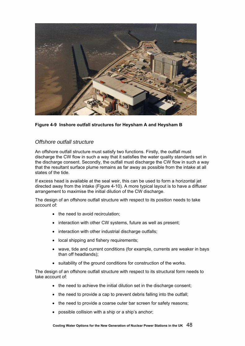
Cooling Water Options for the New Generation of Nuclear Power Stations in the UK 48
Figure 4-9 Inshore outfall structures for Heysham A and Heysham B
Offshore outfall structure
An offshore outfall structure must satisfy two functions. Firstly, the outfall must discharge the CW flow in such a way that it satisfies the water quality standards set in the discharge consent. Secondly, the outfall must discharge the CW flow in such a way that the resultant surface plume remains as far away as possible from the intake at all states of the tide.
If excess head is available at the seal weir, this can be used to form a horizontal jet directed away from the intake (Figure 4-10). A more typical layout is to have a diffuser arrangement to maximise the initial dilution of the CW discharge.
The design of an offshore outfall structure with respect to its position needs to take account of:
• the need to avoid recirculation;
• interaction with other CW systems, future as well as present;
• interaction with other industrial discharge outfalls;
• local shipping and fishery requirements;
• wave, tide and current conditions (for example, currents are weaker in bays than off headlands);
• suitability of the ground conditions for construction of the works.
The design of an offshore outfall structure with respect to its structural form needs to take account of:
• the need to achieve the initial dilution set in the discharge consent;
• the need to provide a cap to prevent debris falling into the outfall;
• the need to provide a coarse outer bar screen for safety reasons;
• possible collision with a ship or a ship’s anchor;

Cooling Water Options for the New Generation of Nuclear Power Stations in the UK 49
• possible wave slam forces if the outfall cap is exposed in the trough of a very large wave;
• the proposed method of access for periodic maintenance.
Figure 4-10 Model of submerged outfall for Kilroot
4.2 Indirect CW Systems
4.2.1 System description
Figure 4-11 shows a schematic arrangement of a typical indirect CW system. The cooling water is pumped from the main CW pumphouse through the condenser to a heat exchanger where it is cooled before it flows under gravity back to the main CW pumphouse. Normally the heat exchanger is a cooling tower which works on the principle of evaporation (see Chapter 2). About one per cent of the main CW flow is transferred to the atmosphere in the cooling tower. A further two per cent of the circulating CW flow is drawn off the system downstream of the condenser in order to prevent the build-up of contaminants in the CW system. The total system losses of about three per cent of the main CW flow are replenished by a make-up water system which pumps water from the primary CW source to the pond under the cooling tower. The purge water is returned to the primary CW source at a point which is remote from the make-up water intake.

Cooling Water Options for the New Generation of Nuclear Power Stations in the UK 50
Figure 4-11 Diagram of typical indirect CW system
4.2.2 Types of cooling tower
Large evaporative cooling towers for power stations may be categorised by type (natural draught, mechanical draught, and hybrid) and characteristics (flow configuration, shape and construction).
There are two classes of flow configuration; counterflow and crossflow. Counterflow is where the flow of circulating water in the tower is in the opposite direction to the flow of air. Crossflow is where the flow of circulating water in the tower is perpendicular to the flow of air.
Other specialised tower designs have been developed to meet particular conditions.
Natural draught towers
A typical natural draught cooling tower comprises a hyperbolic shell structure mounted on leg supports over a circular pond. The circulating water enters the tower and cascades over a slatted structure, referred to as the ‘packing’, mounted above the pond. The packing is the primary heat transfer surface in the tower. Figure 4-12 illustrates the counterflow and crossflow configurations. The draught is driven by the difference in density of the warm moist air inside the tower compared with the cooler air outside the shell. The towers are extremely dependable because the draught is generated by a natural phenomenon.
The hyperbolic shell structure is larger and more expensive than mechanical draft towers. However, a natural draught tower is economic over the life of a station owing to the absence of mechanical equipment.

Cooling Water Options for the New Generation of Nuclear Power Stations in the UK 51
Figure 4-12 Configurations of natural draught cooling tower
Mechanical draught towers
Mechanical draught cooling towers are much smaller than natural draught towers. The mechanical draught required for evaporative cooling can be provided in two ways; a forced draught or an induced draught. The forced draught is generated by fans situated at the air inlet to the tower. The induced draught is generated by fans situated at the air outlet of the tower. Forced draught towers are prone to recirculation because they have high air entrance velocities and low exit velocities. Also forced draught fans can become subject to icing when moving air laden with moisture. Induced draught towers are therefore preferred for power stations. Figure 4-13 illustrates the counterflow and crossflow configurations for an induced draught tower.
Figure 4-13 Configurations of induced draught cooling tower

Cooling Water Options for the New Generation of Nuclear Power Stations in the UK 52
The air entrance velocity for an induced draught tower is typically 2 ms-1and the exit velocity is typically 6 to 8 ms-1. The risks of recirculation and ice formation are substantially less than for a forced draught tower.
Mechanical draught towers can be arranged so the footprint is either circular or rectangular to suit the available site. Many of the components can be fabricated in the factory and the amount of on-site construction work can therefore be minimised.
Hybrid towers
A hybrid tower is a short natural draught tower to which induced draught fans have been added to augment the air flow, Figure 4-14. These towers are also referred to as fan-assisted natural draught towers.
Figure 4-14 Typical hybrid tower arrangement
The purpose of the design is to optimise the cost of running the fans and the cost of constructing the hyperbolic shell of the tower. The hybrid tower can be advantageous when the relatively low level of the discharge plume from a conventional mechanical draught tower is not acceptable. Sometimes the fans only need to be operated during periods of peak load.
Other specialised towers
Dry induced draught towers can be used where make-up water is in critically short supply. The circulating water is passed through finned tube heat exchanger sections for the transfer of heat to the atmosphere. This process depends solely on the dry bulb temperature of the entering air. Consequently the cooled water temperature achieved is typically 11 to 17°C higher than that for a normal evaporative cooling tower.
Water conservation towers can be used where make-up water is available but scarce. This design comprises a group of dry towers linked to an evaporative induced draught tower. The circulating water is passed through the dry towers first. If additional cooling is required, the flow is directed to the evaporative induced draught tower. Conversely, if the temperature of the air-cooled water is adequate the water bypasses the evaporative section of the tower.

Cooling Water Options for the New Generation of Nuclear Power Stations in the UK 53
Conventional cooling towers produce a highly visible plume because the air leaving the tower is supersaturated. The plume abatement tower is designed to reduce the density and persistence of the plume significantly. The design of the tower consists essentially of using a combination of dry and evaporative cooling and mixing the exit air from both processes. The resultant plume is less visible because only part of the plume is supersaturated. The degree of plume abatement depends on the ambient air characteristics and the ratio of dry to wet cooling.
In certain circumstances, plumes from conventional induced draught towers can return to ground level and cause fog-like conditions downwind of the tower. This problem can be avoided by increasing the height of the tower by extending the ’funnels’ above the fans or by increasing the height of the tower structure itself.
Spray-filled towers are towers in which the packing has been omitted. They are used where contaminants or solids in the circulating water would jeopardise a normal heat transfer surface. Their use is normally limited to those situations where higher circulating water temperatures are permissible.
4.2.3 Sources of make-up water
The source of make-up water for a large power station can be virtually any body of water, provided it can sustain an abstraction rate of about 2 m3s-1.
Other less likely sources are groundwater and the effluent from water treatment works.
4.2.4 Design philosophy
Once the decision is made to adopt an indirect CW system, the remainder of the design concept revolves around the choice of cooling tower arrangement, adequacy of the make-up water source, and safe discharge of the purge water.
4.2.5 Design considerations
Choice of cooling tower
Typically, a large (above 1,000 MWe) power station could be served by four 115 m tall natural draught towers or a single 180 m tall tower. The design issues to be considered in deciding the number of cooling towers and the type of tower include:
• visual impact of towers and plumes;
• noise made by water passing through the towers;
• additional noise made by the plant for mechanical draught towers;
• spray nuisance in the lee of towers;
• fog nuisance produced downwind of mechanical draught towers;
• land requirement;
• construction and operating costs.

Cooling Water Options for the New Generation of Nuclear Power Stations in the UK 54
Make-up system
The majority of indirect systems take make-up water from rivers and return the purge water to a point downstream of the intake. Hydrological studies need to be carried out to determine the probability distribution for extreme low river flows, taking into account all other uses of the river. An alternative source of cooling water will need to be found if there is a possibility that river abstraction will not be permitted during periods of low flow, such as a nearby flooded gravel pit.
Cooling towers permit a measure of flexibility in the availability of make-up water. Providing the cooling tower ponds have sufficient capacity a power station can operate for an appreciable time without any make-up, for example for the duration of the tidal cycle below mean sea level.
The intake, screening and pumphouse arrangement for a make-up system is similar to that of a direct CW system but on a much smaller scale. For example, the fine screen can be situated at the intake to exclude fish from the system.
The most common problem encountered is siltation. The usual solution is to permit settlement in the tower ponds and to clean out the ponds on a regular basis. In addition, the make-up water can be de-silted by passing it through a settlement tank before it enters the cooling tower circuit. Whichever measures are adopted, the removed silt has to be disposed of in accordance with waste disposal regulations.
Purge system
The design of the purge water outfall is similar to that of a direct CW system but on a much smaller scale.
4.3 Choice of CW System Past experience in the UK has shown that estuaries or the sea are the only CW source that can support a direct CW system for a large power station. All inland large power stations therefore operate indirect CW systems.
However, greater awareness of the environmental impact of direct CW systems and designation of conservation areas could lead to more use of indirect CW systems in coastal locations. Situations where an indirect CW system may be advantageous include:
• where the environmental impact of the intake and outfall of a direct CW system is not acceptable;
• where the sea can support a direct CW system for one reactor but there is a proposal to develop a power station site with twin reactors;
• where the power station is located on high ground or is several kilometres from suitable abstraction/discharge sites.
A site with twin reactors could have a direct CW system for one reactor and an indirect CW system for the other reactor.
Alternatively, the thermal impact of a direct CW system outfall could be mitigated by a cooling tower in the outfall system (Figure 4-15). Such a tower would be smaller than that for a full indirect CW system because it is only required to reduce the temperature by a few degrees, to comply with the discharge limit. At cooler times of the year it may

Cooling Water Options for the New Generation of Nuclear Power Stations in the UK 55
be possible to bypass the tower and only partial operation of the tower will be necessary.
Figure 4-15 Diagram of typical direct CW system with ‘helper’ tower

Cooling Water Options for the New Generation of Nuclear Power Stations in the UK 56
5 CW system design for new UK nuclear power stations
5.1 Introduction This chapter discusses the civil engineering design of the CW intakes and outfalls anticipated for the proposed construction of the next generation of nuclear power stations in the UK. The following table gives an indication of the CW demand for the two most likely reactor types:
Table 5-1 Electrical out put and CW demand for the EPR and AP1000 reactors
Reactor Electrical Power Output CW Demand (m3s-1) EPR 1,600 72 AP1000 1,117 57
5.2 Potential sites and water sources The site of any new power station is ultimately chosen by balancing a wide range of environmental, engineering, technical and commercial considerations. The main civil engineering considerations are:
• ground conditions;
• availability of cooling water;
• proximity to an existing connection to the national grid;
• transport access to the site for the workforce, materials and heavy loads.
Between 1953 and 1963 eleven Magnox stations were built in the UK. The majority of the sites were selected by the then Central Electricity Generating Board (CEGB) after a considerable amount of work (CEGB, 1986). Since 1965, three advanced gas-cooled reactor (AGR) stations and one PWR station have been built alongside four of the Magnox stations (Dungeness, Hinkley Point, Hunterston and Sizewell). In addition, new AGR stations have been built at Hartlepool, Heysham, and Torness. All the current nuclear stations are coastal and each has a direct CW system with a flow in the order of 50 cumecs, somewhat lower than may be expected in the future (Table 5-1).
The proposed third generation of nuclear reactors will have a generation capacity of between 1,200 and 1,600 MWe. The power stations will probably require a direct CW system with a CW flow of between 40 and 80 cumecs per reactor, depending on the temperature rise through the turbine condenser.

Cooling Water Options for the New Generation of Nuclear Power Stations in the UK 57
It is therefore anticipated that the CW system for each of the proposed new reactors will be one of:
• a direct CW system built at an existing Magnox or AGR site where there is room to expand;
• an indirect CW system built at an existing Magnox or AGR site where there is room to expand but there is a need to mitigate the environmental impact;
• a direct CW system built at a new coastal site;
• an indirect CW system built at a new coastal site where there is a need to mitigate the environmental impact;
• an indirect CW system built at an existing or new inland site with a reliable source of make-up water.
If the CW system option is an indirect system, the make-up water flow will probably be between two and three cumecs.
British Energy has already published Environmental Scoping Reports for four possible new nuclear stations at Hinkley Point, Sizewell, Bradwell and Dungeness19. In all cases it is likely that the plant will be directly cooled, with no need for cooling towers.
5.3 Basis of design This section discusses the civil engineering design of the CW intake and outfall for the direct CW system only. The design of the CW intake and outfall for the indirect CW system is omitted because it would be similar to the design of the many intakes and outfalls that already exist for the major inland power stations in the UK, such as Drax.
The final design of a direct CW system for a reactor will be site-specific because it will depend on unique site characteristics such as ground conditions, topography, bathymetry, tidal range, current regime, ecology and meteorology. It is therefore not practicable to derive specific design recommendations that will be applicable to all possible reactor sites. However, the discussion will cover the general principles of the engineering design and these principles can be transferred to any site.
5.4 CW intake design
5.4.1 Offshore intake
Offshore intake for deep intake conduits
Figure 5-1 shows a typical submerged offshore intake structure for a deep tunnel intake conduit. The structure is a capped radial flow structure, constructed in precast concrete and placed on a prepared granular foundation. 19 http://www.british-energy.com/documents/Hinkley_Point_Environmental_Scoping_Report.pdf http://www.british-energy.com/documents/Sizewell_Environmental_Scoping_Report.pdf http://www.british-energy.com/documents/Bradwell_Environmental_Scoping_Report.pdf http://www.british-energy.com/documents/Dungeness_Environmental_Scoping_Report.pdf (viewed 10.03.09)

Cooling Water Options for the New Generation of Nuclear Power Stations in the UK 58
Figure 5-1 Typical submerged intake structure
The design is based on the assumption that tidal currents are small, less than 0.1 ms-1. If tidal currents are such that fish could be carried into a radial flow structure, the hydraulic design of the structure will need to be modified. Upstream and downstream openings of the intake will have to be closed off to ensure intake only draws water in a direction perpendicular to the tidal flow. Such a design exists at present only as a concept that has undergone limited model-testing and will have to be fully evaluated by physical modelling to ensure the resultant velocity through the intake screen will not draw in fish (Section 6.1.6).
The number and diameter of the deep tunnels will probably be decided by the construction contractor. A single tunnel would be adequate for the operation of the power station. Inspection and maintenance of the tunnel could be carried out using underwater engineering techniques during one of the scheduled plant outages (CEGB, 1986). However, access is usually impractical over distances of more than 500 m from either end, unless intermediate entry points are provided, because of limits on diver access and on the use of remotely operated vehicles (ROVs) because of cable drag. The diameter of the vertical shafts needs to be as large as possible for economy and may also be decided by the construction contractor. The number of shafts will be decided by the total design CW flow and the optimum flow per shaft.
It is envisaged that the vertical shaft to the deep tunnel will be drilled from a jack-up barge. The shaft will then be flooded, the section of lining above the seabed removed, and the intake structure placed in position. Temporary isolation gates will be fixed to the intake structure to enable the shaft to be dewatered so that the connection to the

Cooling Water Options for the New Generation of Nuclear Power Stations in the UK 59
deep tunnel can be completed in dry conditions. On completion of the tunnel and shaft works, the intake structure will be commissioned by flooding the offshore system and removing the temporary isolation gates.
Comments on the detailed design of the submerged offshore intake structure are listed in Table 5-2.
Table 5-2 Detailed design of submerged offshore intake structure
Aspect of design Comment Design low water The design low water level adopted for the intake must be one
that occurs very infrequently, but there are no hard and fast rules for determining this level. Lowest astronomical tide (LAT) is the predicted tide level that is equalled or exceeded only once in a cycle of 19 years although in practice LAT can be exceeded several times a year through meteorological effects. Invariably a margin of safety is included and the designer must check the impact on intake performance if the chosen DLW level is exceeded.
Submergence The minimum depth of water above the intake screen should be designed to avoid the following at design low water: air being drawn into the intake by the formation of a surface-piercing vortex; the intake cap being exposed in the trough of a wave; and excessive recirculation caused by drawing in warm water from the outfall plume.
Screen area The required screen area is governed by the design flow for the vertical shaft and the required uniform velocity through the intake screen that will allow fish to escape.
Screen height The screen height needs to be as large as possible to minimise the diameter of the intake structure and facilitate access by divers for maintenance and cleaning. However, the height must not be so large that the velocity through the intake screen is not uniform with depth.
Screen diameter The screen diameter needs to be as large as possible to ensure the velocity through the intake screen is uniform with depth. However, the diameter must also be within the appropriate limit for handling the intake as a prefabricated unit.
Screen construction The dimensions of the intake screen depend on the type of fish or other biota to be excluded. A typical arrangement would comprise rectangular bars 16 mm wide and 50 mm deep, at 90 mm centres. The material of the bars could be mild steel protected by a suitable corrosion protection system. Alternatively the bars could be constructed in stainless steel or a non-ferrous metal that inhibits marine growth. Consideration should be given to making the screen in removable sections to facilitate maintenance and cleaning.
Screen protection Consideration should be given to coating the intake screen bars with antifouling paint to prevent biofouling. The coating would need to be replaced approximately every five years.
Sill height The sill of the intake should be high enough above seabed level to prevent sediment and debris being drawn from the seabed into the intake. This also reduces the risk of drawing in benthic fish.
Structure diameter The diameter of the structure at seabed level should be as small as possible to minimise the impact of the structure on the

Cooling Water Options for the New Generation of Nuclear Power Stations in the UK 60
Aspect of design Comment sediment transport regime in the vicinity of the structure.
Foundation The foundation should be designed for stability under the imposed dead and live loading including the combined hydrodynamic loading from the CW flow, extreme currents and extreme waves. The seabed should be excavated and replaced with suitable rock fill material if the seabed is soft below the foundation formation level.
Scour protection The sea bed around the intake structure should be reinforced with rock armour to prevent erosion of the bed due to increased turbulence in the vicinity of the intake structure.
Biocide dosing system
A system will be required for delivering the biocide to each intake structure in equal quantities. The pipeline can be internal (incorporated within the deep tunnel) or external (lain on the seabed). The pipeline could be prone to blocking and must therefore be designed for full maintenance and replacement if necessary. The biocide should be discharged from a diffuser designed to release the biocide close to the surfaces of the intake immediately downstream of the intake screen. The biocide cannot be released in front of the screen because of the risk that some of it may not be carried into the intake.
AFD system To meet Best Practice, the intake should be fitted with an acoustic fish deterrent (AFD) system (Section 6.1.5).
Diver access A hatch should be provided in the cap of the intake so that divers can gain access to the intake for inspection and maintenance.
Isolation gates Gate supports and guides should be provided to enable the intake to be isolated and dewatered during construction as well as for possible subsequent maintenance during the life of the power station.
Corrosion protection The choice of metals should ensure that corrosion cells are not set up which have a harmful effect on the intake structure.
Navigation The location and extent of the CW intake should be marked with appropriate navigation aids to satisfy the requirements of the local navigation authority. The design of the intake structure should be checked for accidental ship collision.
The minimum depth required for an offshore intake is site-specific. Typically, a minimum depth of 8 to 10 m below LAT could be required. The position of an offshore intake is also site-specific and needs to be decided in conjunction with the outfall position. In addition, the intake must be located in an area where the seabed is open and free from obstructions so the intake can draw in the CW flow without distorting the ambient flow regime significantly.
Offshore intake for shallow intake conduits
If the offshore intake conduits are constructed by the immersed tube technique, the intake structures will probably be constructed as an integral part of the immersed tube units. Comments on the detail design of the intake structure are the same as Table 5-2 with one exception. The need for isolating gates does not apply to shallow offshore intake conduits because they cannot be dewatered owing to flotation.
A key aspect of the immersed tube design is that major temporary works are required in the inter-tidal zone where the offshore construction method changes to the onshore construction method (Figure 5-2). These works can have an environmental impact.

Cooling Water Options for the New Generation of Nuclear Power Stations in the UK 61
Figure 5-2 Temporary works for immersed tube construction, South Humber
5.4.2 Inshore intake
The detailed engineering design of an inshore intake depends on whether the intake is in a sheltered location (Figure 4-3) or an exposed location (Figure 4-4). Essentially the civil engineering structure will be subjected to coastal processes and will need to be designed to take account of tidal range, current regime, wave action and sediment transport under prevailing and storm conditions.
The design comments in Table 5-2 are also generally applicable to inshore intakes. In particular, the comments with respect to design low water, submergence, screen area, screen construction, screen protection, sill height, scour protection, biocide dosing system, AFD system, corrosion protection and navigation are relevant.
5.5 CW intake screening
5.5.1 Why cooling water needs to be screened
Power stations usually require multiple CW screening systems to prevent the entry of unwanted debris, biological detritus and living organisms into the tunnels and various parts of the plant where they might cause damage or operational difficulties through blockage of flow. Any new directly cooled coastal plant should provide equipment to ensure that the plant can operate at its normal capacity for nearly all of the time.
Screening is required not only to protect the plant but also for public safety (divers, swimmers and anyone falling into the water) and for the exclusion of fish, marine mammals, diving birds and other biota. Protection of aquatic life is a relatively recent

Cooling Water Options for the New Generation of Nuclear Power Stations in the UK 62
factor in intake screening design and was seldom taken into account in CEGB power station designs prior to the 1970s, except in special cases such as Oldbury-on-Severn and Pembroke power stations, where rudimentary fish rescue systems were contrived to assist the return of entrapped salmon and sea trout smolts to the wild20.
Some sites are particularly prone to invasions of biota, such as sprat shoals or jellyfish, while others may be afflicted by inundations of kelp and other seaweeds. Although careful planning and siting help to minimise these risks, environmental conditions can change and the unexpected can occur. Even without these transient events, everyday loadings of screening systems can be large, representing an environmental nuisance and disposal cost that stations would prefer to avoid.
The main reason for installing screening at any power station is to protect the downstream equipment. The first item is the main CW pump that moves the water through the cooling cycle. Modern concrete volute pumps or vertical spindle mixed flow pumps generally can tolerate particles of 25 mm in diameter without problems. However heat transfer takes place in the condenser, usually constructed with tubes having an internal diameter of between 20 and 25 mm, through which the cooling water flows to cool the steam passing through the condenser on the outside of the tubes. A standard condenser will have many hundreds of tubes and the heat transfer efficiency is vital to the overall performance of the power plant. It is usual practice today to have screen openings one-third of the condenser tube internal diameter, that is 6-8 mm. In almost all of the screens in current UK power stations, nuclear or conventional, the mesh installed on the band screen or the drum screen is between 5 and 10 mm.
An important factor influencing the size of screen mesh is hydraulic head loss: the smaller the mesh, the greater the head loss. With the large flows of water involved, the pumping energy must be taken into account. Head loss increases as a square of the velocity and the smaller the mesh the greater the head loss will be, as velocity of water passing through the mesh for a given flow will increase with reduction in the open area of finer meshes. Increasing the size of the screening plant can offset this. The size of the screening plant is therefore selected at the design stage and later reductions in mesh size may be difficult.
Finer meshes also remove more debris, and are more prone to blockage, a further factor that needs to be taken into account.
In other processes within the cooling plant, a much smaller mesh size may be needed to protect, for example, electro-chlorination equipment or screen wash water jets. In these cases, as the water quantities are small, separate automatic pipeline strainers are employed and these can polish the water to the required degree, usually to 0.5-1.5 mm.
5.5.2 Stages of screening
Modern CW intake designs therefore incorporate up to four levels of water screening:
• coarse or fine screening at the primary intake point;
• onshore coarse screening, ahead of fine (drum or band)screens;
• main plant fine screening by band or drum screens;
• auxiliary cooling water supply filtration.
20 Unpublished CEGB report Smolt recovery system, results of 1970 run, Oldbury-on-Severn Power Station, M-OLD-CWE-1110

Cooling Water Options for the New Generation of Nuclear Power Stations in the UK 63
The requirement for each of these stages depends on preferences of the designer, as well as local site-specific factors such as debris concentrations in the water.
5.5.3 Screens located at intake point
Coarse screens with bar spacings of between 50 and 250 mm (typically around 90 mm) are normally used at this stage to prevent entry of large items such as plastic drums or tree branches as well as marine mammals, diving birds and divers or swimmers.
Coarse screens of heavy-duty treated steel bar or stainless steel construction are on most modern stations aligned vertically across the intake ports or around the periphery of capped offshore structures. Some older CEGB stations (such as Sizewell A, Dungeness A) which had no cap on the intake used a cylindrical bar cage surmounted by a conical array of radial bars (‘Chinese hat’ type). This arrangement is now not used since it allows water to be drawn vertically, increasing risk of surface vortex formation (a danger to craft and swimmers) and of abstraction of warmer surface layers. At Hinkley Point A & B station, which share a common intake caisson located 500 m offshore into the Bristol Channel, water enters via coarse screens fitted to both the sides and the top of the structure. In none of the offshore structures is any automated raking mechanism provided, owing to the hostile sea conditions to which these structures can be exposed. The screens do, however, biofoul and clog with rope, fishing nets and other debris with time and these accretions have to be removed by divers during planned outages.
Where the intake is located offshore, some station designs (such as Sizewell A, Dungeness A, Hinkley Point A & B) have provided a superstructure over the intake. The main purpose has been to support a crane to allow fitting and removal of an intake plug for dewatering purposes. In practice it was found that the structures were difficult to access safely from the sea and became a health and safety risk and a maintenance liability. Those at Sizewell A and Dungeness A were therefore removed during the 1980s. The exception is at Hinkley Point, where an extra culvert was installed as a pedestrian tunnel, which provides access from the shoreline. Turnpenny (1988a) points out that excessive structure around an intake inadvertently creates an artificial reef, increasing the risk of attracting fish into the intake. Nowadays, superstructure is normally confined to that required to support navigation lights and any fish protection systems (see Section 6.1.5).
Wharfside intakes built at the shoreline are normally fitted with vertical bar screens set into the intake openings. It is unusual to provide raking mechanisms but since the locations are more sheltered it is usually feasible to do so in locations where the trash loading is high. For example, Keadby CCGT Power Station on the Trent estuary at times draws in large quantities of brushwood and dead straw-like vegetation and has been fitted with an automated raking machine to alleviate this problem (Figure 5-3). Keeping screens clear of blockage is important, as stations may otherwise breach abstraction licence conditions relating to maximum allowable velocities for fish protection.

Cooling Water Options for the New Generation of Nuclear Power Stations in the UK 64
Figure 5-3 CW intake at Keadby, showing overhead gantry rail for screen raking system and accumulated brushwood
Some smaller tower-cooled CCGT stations use passive fine screens at the primary intake point. UK examples include the Deeside, Connahs Quay (both Welsh Dee) and Killingholme (Humber) stations, all located on estuaries. These are known as passive wedge-wire cylinder (PWWC) screens, and the screening elements are formed by triangular-section wires wrapped around a cylindrical former (Figure 5-4). The wire spacing is generally specified as 3 mm; this and the design through-slot velocity of under 0.15 ms-1 prevent entry of all but the smallest fish larval stages. The screens work best when located in a sweeping flow that exceeds 0.3 ms-1 for a high proportion of the time, as this carries away debris and assists in fish escape (Turnpenny and O’Keeffe, 2005). In 2005, when Jacobs reviewed operating experience of PWWC screens, the Connahs Quay station reported good operational performance in the eight years or so since its construction, while at Deeside intermittent blockage problems were reported. At Connahs Quay, the screens are placed well out into the estuary channel, encouraging debris clearance, while at Deeside the screens are recessed into the bank and out of the channel flow.
PWWC screens remain an unproven technology anywhere in the world in marine waters as hostile as those offshore in the UK (eg significant tides, waves and currents etc). The large CW requirements, and consequently huge screen array sizes, combined with the risk of catastrophic blockage, for example by a sudden influx of seaweed during a storm, has so far been thought to make their use unsuitable for nuclear applications.
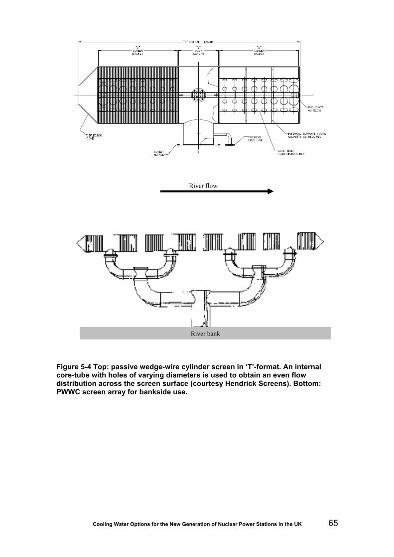
Cooling Water Options for the New Generation of Nuclear Power Stations in the UK 65
Figure 5-4 Top: passive wedge-wire cylinder screen in ‘T’-format. An internal core-tube with holes of varying diameters is used to obtain an even flow distribution across the screen surface (courtesy Hendrick Screens). Bottom: PWWC screen array for bankside use.
River flow
River bank

Cooling Water Options for the New Generation of Nuclear Power Stations in the UK 66
5.5.4 Forebay bar screens
While not found on British nuclear sites of the CEGB era, it is now common for directly cooled power stations to install automatically raked bar screens into the forebay ahead of the drum or band screens. Such bar screens typically have a clear spacing of 50 mm. The raking mechanism is similar to that shown Figure 5-3, and one rake normally traverses all the screen sections either at preset time intervals or when a head differential is detected across the screen. In the UK, these intermediate bar screens are to be found, for example, at Great Yarmouth and South Humber Bank, both directly estuary-cooled CCGT stations. In continental Europe they are also used at the Doel nuclear plant on the Scheldt Estuary in Belgium.
The use of forebay raked screens is becoming more common and they may well be used to reduce fine-screen loading on new nuclear stations, especially where drum or band screens are fitted with a mesh finer than the 8-10 mm common on CEGB-era stations. An important consideration will then be their ability to handle larger fish safely. Fish recovery and return (FRR) systems presently in use rely on the band or drum screens to handle the fish and, to date, little or no thought has been given to damage that may be incurred at this stage. First, it should be recognised that larger fish may become pinned to the screens for long periods between raking operations; secondly, the lifting mechanisms will be unlikely to retain larger fish such as eels and adult lampreys, which may as a consequence be subject to multiple handling by the rakes before successful removal.
Observation of the operation of raking systems has revealed that problems can occur when the flow conditions into which they are installed are not fully understood. It is not uncommon to see debris that has been brought up by the rake to the top of the screen being washed off again before exiting the water by upwelling currents in front of the screen. Regulators should be satisfied that the design and performance of any forebay raking system is compatible with FRR requirements (see Section 6.1.6).
5.5.5 Fine screening
Travelling band screens
Travelling band screens (or just ‘band screens’) comprise articulated bands of mesh panels attached to chains driven by sprockets (Figure 5-5). The band of moving mesh is introduced in front of the pumps, the screens elevating debris from the water to deck level where it is washed off by water jets. As more sophisticated travelling band screens have been developed, they have changed from straight-through type to dual flow and centre flow, referring to the flow pattern of water passing through the screen:
• Straight through – All of the water passes from one side to the other through both the ascending and descending sides of the moving band.
• Dual flow – Mesh panels move parallel to the flow, half passes from outside of the centre through the ascending side of the band, half passes from the outside to the centre through the descending side of the band, all of the water passes out through a single exit often referred to as the back opening. This type of screen is used in the UK and France.
• Centre flow – This machine also has panels positioned parallel to the flow but in this case all of the water passes into the centre of the machine with

Cooling Water Options for the New Generation of Nuclear Power Stations in the UK 67
half passing out through the descending side and half through the ascending side. This type of screen originated in Germany and is still the German standard.
These flow patterns are shown below in Figure 5-6.a, b and c.
Figure 5-5 Engineering drawings of travelling band screen: vertical section (left) and elevation (right)
(a)
Bandscreens: Flow Pattern
Through Flow (TF):
• Can “carry over”. • Produces a parallel flow. • Simpler civil work requirement than for
DF or CF types. • Flow has to pass through the mesh
twice, can lead to higher head losses with fine mesh.
• Predominately used in USA.

Cooling Water Options for the New Generation of Nuclear Power Stations in the UK 68
(b)
Bandscreens: Flow Pattern
Dual Flow (DF):
• No “carry over”.
• Produces a converging flow, therefore suitable for close coupling to CW pump.
(c)
Bandscreens: Flow Pattern
Central Flow (CF):
• No “carry over”. • Produces a diverging flow, therefore
not suitable for close coupling to CW pump.
• Good for heavy/large solids quantities,
therefore commonly used on waste water applications.
Figure 5-6 Characteristics and flow arrangements for travelling band screens in plan view: a) through-flow, b) dual flow (UK and France), c) central flow (Germany)
In the late 1920s there were parallel developments in the UK and France of an alternative type of screen. The need for this screen was driven by a number of factors.
• The moving band of mesh panels on a band screen are carried on a chain comprising links, pins, bushes and rollers. A single machine can have 2,000 moving parts, all of them operating in sea or river water containing sand or silt. As there are often several units on a single plant, the spare part and labour costs are a significant factor in plant running costs.
• A modern power plant or industrial complex may need 50 to 100 m³s-1 CW, whereas a single band screen has an upper limit of 10 m³s-1 capacity, governed by the structural integrity of the machine. With the need for standby machines, high capital and running costs become a major factor in screen type selection.
These constraints led to development of the rotating drum screen. The 1930s saw an increase in the use of drum screens in France and the UK. Curiously, the drum screen concept never evolved in Germany or America. In France, development was led by Beaudrey and in the UK by F.W. Brackett (now Eimco Water Technologies). These two variants will be referred to here as the French and British designs, respectively.
Owing to the large CW requirement of nuclear plants, drum screens are much more likely to be used in UK new nuclear build for fine screening than band screens. One important aspect of this outcome concerns fish recovery and return methods, which, at present, are simpler to install and therefore further advanced on band screens than on drum screen systems.

Cooling Water Options for the New Generation of Nuclear Power Stations in the UK 69
Drum screens
Drum screens are much simpler in construction than band screens, comprising a slowly revolving mesh cylinder through which the water is passed. This essentially has only one moving part, the screen itself, although a drive motor and washwater pumps are required as well.
In the UK the drum screen evolved with a water flow pattern of ‘in-to-out’, water passing into the middle of the screen from both sides (in the case of double-entry drum screens) and outwards through the mesh, catching and arresting all the debris on the inside of the screen (Figure 5-7a).
In France the drum screen evolved using a flow patter of ‘out-to-in’ water passing from the outside of the drum through to the centre of the drum, retaining debris on the outside of the drum (Figure 5-7b).
There are variations of orientation in both types and when water passes into the screen from one side only (in the case of ‘in-to-out’ screens) these are designated single entry drum screens (SE); the ‘out-to-in’ flow pattern can also be arranged with the main shaft parallel to or at right angles to the flow. These variations are often related to site constraints or pump station layouts.
(a) In-to-out
The in-to-out flow pattern produces a converging flow. This minimises the outlet turbulence and distance required between the screen outlet and CW pump inlet.
(b) Out-to-in
The out-to-in flow pattern produces a diverging flow that can result in turbulence at the outlet and requires the flow to be converged to meet the CW pump inlet, increasing the distance between screen and CW pump.
Figure 5-7 Schematic showing in-to-out (UK) versus out-to-in (France) drum screen design concepts

Cooling Water Options for the New Generation of Nuclear Power Stations in the UK 70
The upper limit of a single drum screen is typically around 35 m³s-1, well above band screen capacity. Multiple screen installations with four per site are common on UK and French sites. Of these, three may be adequate to handle the full CW flow but a fourth provides a standby and additional capacity that can be brought online as required. Nuclear plants often operate all four screens continuously.
Interestingly, the French steadfastly have stood by their ‘out-to-in’ concept and the British, their ‘in-to-out’ concept. The following is a summary of the statements that British and French screen suppliers regularly make in putting their cases forward.
For the French system, the manufacturers state the benefits of their out-to-in concept as follows:
• Debris remains on the outside of the drum screen and is visible to the operator.
• Spray water jets (by virtue of the design) are on the inside of the screen and are easily accessible.
• The drum screen floats if the mesh becomes blocked to the point where holding down bolts snap.
• Gravity is of no assistance in removing debris from the screen and only the washwater pressure is significant.
• Due to the tendency of the screen to float, bearing loads and drive power requirements are reduced.
• Debris cannot fall off the screen.
• The trash collection trough is continuous over the full width of the screen.
• The depth of the screen sump can be reduced with out-to-in screens.
• Screens with out-to-in flows can be constructed to larger sizes.
For the British system, the manufacturers state their arguments promoting the in-to-out flow as follows:
• Washwater jets are vital to the operation of the screen; these are external to the screen and easily accessible without stopping the screen.
• Debris is removed from the screen by a combination of gravity and low pressure washwater.
• Hydraulic loads are absorbed by the concrete structure.
• Drive gear is external and therefore always accessible.
• Roller bearings are designed to last the life of the screen.
• The screen is hydraulically balanced.
• Flow to the pump is laminar and not turbulent.

Cooling Water Options for the New Generation of Nuclear Power Stations in the UK 71
Figure 5-8 Further comparison of out-to-in and in-to-out drum screen designs
A drum screen of either configuration will only continue to operate if the screen presents a clean mesh surface to the water being screened. Washwater jets clean the mesh by sending a fan of pressurised water to remove debris from the screen. Jets do unfortunately occasionally block. Jets on the in-to-out type of screen are accessible from the operator’s platform without stopping the screen. On the out-to-in, screen jets
Spray jets are located inside the screen, which can give rise to maintenance problems, as they can only be cleaned or replaced with the screen.
Trash has to be backwashed against gravity and then captured by the hopper. This requires high wash-water pressure and consequently gives higher operational costs.
Gravity works against the lifting of trash, which can fall back when the water level is below the screen centre-line.
Headloss across screen gives rise to a down-thrust, which results in compressive forces in the civil works supporting the main bearings (concrete is at its strongest in compression).
Spray-jets are accessible for maintenance, without stopping the screen.
Trash is backwashed with the assistance of gravity, falling directly into hopper.
Trash moves naturally to the elevating face of screen (particularly important with dense trash such as jellyfish).

Cooling Water Options for the New Generation of Nuclear Power Stations in the UK 72
are inside the screen, the screen has to be stopped before a jet can be cleaned. British screens require 1.7 Bar pressure to clean the mesh while French screens require 3.0 Bar. Low pressure sprays are beneficial for safe fish recovery (see Section 6).
British screens elevate the debris to the rubbish hopper with internal elevating trays, French screens with external elevating trays. The rubbish hopper on the British screen is positioned about 30º from vertical and is thus positioned to ensure that elevators tip their contents into the rubbish hoppers. During the 1.5 to two metres of travel over the rubbish hopper, low pressure water flushes debris (and live fish) from the mesh with the aid of gravity. With the French design, debris has to be blown off the mesh against gravity (Figure 5-8), a system that would more likely damage live fish as they have to be knocked off the mesh into the external rubbish hopper. This may be of concern when considering adaptation of the screens for FRR (Section 6.1.6).
Use of band and drum screens in other countries
The advantages of drum screens have been recognised in almost every country where large sea, river and estuary intakes are used. Manufacturers’ supply tables (Beaudray, Eimco Water Technologies) give an indication of their geographic use. The French manufacturers have supplied around 500 drum screens; of these, 250 are in France, 60 are in Holland, 27 are in Belgium, others in various parts of the world. Eimco (formally Brackett) has supplied around 1,100 drum screens, of which 71 per cent were exported from the UK.
China, which is a rapidly growing market for nuclear and coal-fired plants, has adopted the in-to-out design. Hong Kong has virtually always built plants with the in-to-out flow pattern and following its reintroduction to China, has continued this trend.
China tried the out-to-in screens in 1987; six were installed at the Daya Bay plant in Guangdong. Following that, four in-to-out screens were purchased for Ling Ao 1 and after two years of operation four more were ordered for Ling Ao II. Quinshan and Dalian followed with in-out designs: a total of 20 drum screens. All the new plants planned in China are intending to use in-to-out drums.
However, of two nuclear power plants using EPR reactors being built in Europe one, Olikiluto in Finland, has selected band screens. The other, at Flammanville in France, has selected out-to-in drum screens.
Around the world, there are many hundreds of screens installed at sites with flow configurations out-to-in, in-to-out and with dual and single exits. It is important that pump suppliers have no issues with the type of screen that is protecting their pumps as the screen can often affect pump performance and, beyond the pumps, downstream equipment such as condensers, plate heat exchangers or other process equipment.
On large projects a model test is often carried out and can reveal performance problems or hydraulic concerns. Testing facilities are found at organizations such as HR Wallingford or Hydrotech in the UK or Alstom at Nantes in France.
In conclusion, the out-to-in flow pattern is predominantly used in France and in-to-out flow pattern is the established norm in the rest of the world. However, Beaudrey are able to build in-to-out screens and there are around 20-25 units in their reference list of in-to-out configuration. In recently built and upcoming nuclear power plants to be built by French contractors or developers outside of France, the in-to-out flow pattern has been selected. Examples are: (Alstom) Nuclear 1 South Africa, (Alstom) San-Men China, (CGNPC) Ling Ao1 and Ling Ao 2.
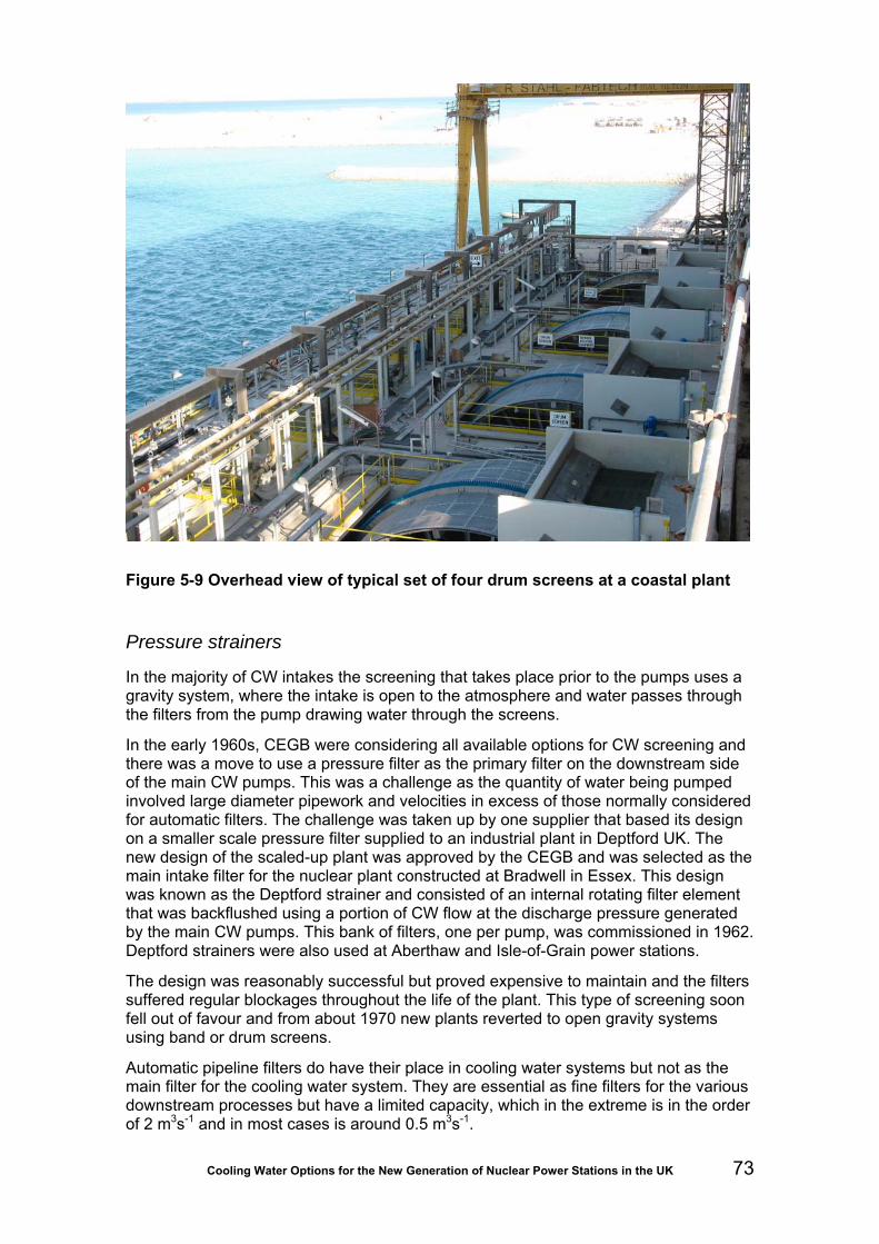
Cooling Water Options for the New Generation of Nuclear Power Stations in the UK 73
Figure 5-9 Overhead view of typical set of four drum screens at a coastal plant
Pressure strainers
In the majority of CW intakes the screening that takes place prior to the pumps uses a gravity system, where the intake is open to the atmosphere and water passes through the filters from the pump drawing water through the screens.
In the early 1960s, CEGB were considering all available options for CW screening and there was a move to use a pressure filter as the primary filter on the downstream side of the main CW pumps. This was a challenge as the quantity of water being pumped involved large diameter pipework and velocities in excess of those normally considered for automatic filters. The challenge was taken up by one supplier that based its design on a smaller scale pressure filter supplied to an industrial plant in Deptford UK. The new design of the scaled-up plant was approved by the CEGB and was selected as the main intake filter for the nuclear plant constructed at Bradwell in Essex. This design was known as the Deptford strainer and consisted of an internal rotating filter element that was backflushed using a portion of CW flow at the discharge pressure generated by the main CW pumps. This bank of filters, one per pump, was commissioned in 1962. Deptford strainers were also used at Aberthaw and Isle-of-Grain power stations.
The design was reasonably successful but proved expensive to maintain and the filters suffered regular blockages throughout the life of the plant. This type of screening soon fell out of favour and from about 1970 new plants reverted to open gravity systems using band or drum screens.
Automatic pipeline filters do have their place in cooling water systems but not as the main filter for the cooling water system. They are essential as fine filters for the various downstream processes but have a limited capacity, which in the extreme is in the order of 2 m3s-1 and in most cases is around 0.5 m3s-1.

Cooling Water Options for the New Generation of Nuclear Power Stations in the UK 74
5.5.6 Trash handling and disposal
Both band and drum screens are designed to backwash any filtered debris and biota into troughs, known as ‘launders’, which convey the material into a collecting basket or some other receiver. Washwater pumps, usually abstracting from the screenwell, supply both the spray jets that clean the screens and the water to flush debris along the troughs. Flow rates are usually quite low, in the order of 4 ls-1 per screen and pressures may range from between one and four bar, depending on manufacturer (see above discussion of drum screens).
At most CEGB sites, operating licences required backwashed debris to be drained and transported off site to landfill. This remains the case at most sites today. In a few cases, debris is put back to sea via the thermal discharge culvert, either direct from the screens or after maceration.
In all cases, stations require consents for disposal back to water. This is now commonplace where fish recovery and return (Section 6.1.6) is operated.
5.6 Biofouling control
Main cooling and auxiliary circuits
The extensive submerged surfaces of cooling water (CW) circuits offer ideal conditions for the growth of bacterial and fungal slimes (micro-fouling) and of large sessile organisms such as mussels, barnacles and hydroids (macro-fouling). These organisms arrive mainly as spores and larvae that pass easily through the screens protecting the intakes. Once settled, the steady flow conditions provide an abundance of food whilst hindering the establishment of motile predators. Macro-fouling can restrict flow and cause blockages and leaks in condensers and heat exchangers, leading to reduced efficiency and plant outages. Even a thin film of slime can significantly reduce heat transfer across heat-exchange surfaces, whilst beneath it corrosion may be accelerated. The lost output from these causes would have to be replaced from potentially older, less-efficient stations.
Many approaches have been tried to combat biofouling but the majority, both chemical and non-chemical, have proved to be ineffectual and most operators favour continuous low-level chlorination (Turnpenny & Coughlan, 1992; Jenner et al. 1998; BREF, 2000). Chlorination has the advantage of a long track record of human and environmental exposure, unmatched by any of the alternatives. Some, such as ozone, bromine chloride, and hydrogen peroxide, produce essentially the same byproducts as does chlorination so, despite their higher cost, there is no benefit to the marine environment. Although chlorine gas is a powerful respiratory poison, in dilute solution it is an effective, broad spectrum disinfectant. The level used for marine biofouling control (0.2-0.5 mgl-1) is significantly less than that found in most drinking water (5.0 mgl-1). The use of chlorine gas at UK power stations was discontinued many years ago and was replaced by electrochlorination and sodium hypochlorite (a chlorine source best known as household bleach). The biocidal activity of chlorine solutions is related to their ability to oxidise and they are often referred to as “oxidant”. The main period of chlorination will be when sea temperatures exceed 10°C, typically from May to November. Some oxidant inevitably will be discharged with the cooling water. This constitutes a waste, as well as a potential threat to the environment, so the dosing will be carefully controlled. Sometimes it is feasible to chlorinate only part of the CW flow at any one time and the recombination of treated and untreated streams will reduce

Cooling Water Options for the New Generation of Nuclear Power Stations in the UK 75
oxidant concentrations prior to discharge. This is not possible with a single CW intake and tunnel. The discharge concentration is regulated by the Environment Agency; consent levels have been progressively reducing to a common 0.2 mgl-1 (200 µgl-1) and there is now a proposed interim UK EQS of 10 µgl-1, possibly decreasing to 1.0 µgl-1. After discharge, concentrations continue to diminish through further dilution, additional demand introduced by the receiving water and by continuing decay reactions. Electrochlorination results in the release to atmosphere of hydrogen gas (one molecule of hydrogen for each molecule of chlorine), which represents a small but possible explosion risk on site. The seawater leaving the electrolyser cells usually enters a tall, open-topped cylindrical “detraining” tank from which hydrogen is released to the atmosphere. An alternative method (not from one of the market leaders) uses a mechanical ventilation system that abstracts hydrogen from the top of the electrolysers. The detraining tanks or ventilation stacks have to be sited clear of other buildings and at some sites (such as China’s Pearl River delta where thunderstorms are frequent) they are surrounded by lightning conductors. A combination of muco-polysaccharides and outgassing hydrogen in the detraining tanks can result in the formation of lighter-than-air foam (hydrogen surrounded by sodium hypochlorite) that can be blown around the site. This poses a risk to eyes and skin, to metal and concrete structures and, as the foam settles to the ground once sufficient hydrogen has diffused out of it, substantial drifts may accumulate in sheltered corners. These drifts are an explosion hazard. Foam formation can be minimised by water sprinklers at the top of the detrainment tanks.
Inlet works surface coatings
Chlorine and other soluble biofouling control chemicals may not be viable upstream of screening systems where fish recovery and return (FRR) is practiced, owing to potential toxicity to fish (see Section 6.1.6 below). Without treatment, there is a risk at some locations that the surfaces of inlet tunnels, forebays and screenwells across which seawater is flowing will develop fouling. This can impede flow and may slough off and block screens. Where spare tunnels and so on are provided, they may be taken offline and treated periodically by shock dosing with a soluble biocide. Alternatively, various kinds of biofouling-resistant coatings can be used to treat the surfaces at risk. At present, this is a relatively new issue that has arisen from best practice advice (Turnpenny and O’Keeffe, 2005) and some guidance may therefore be helpful.
Non-toxic coatings Non-toxic coatings work by creating non-stick surfaces on which fouling cannot settle or, if settled, can be pulled off by currents - hence the alternative name of foul-release coatings. There are two categories of non-toxic surface: ablating hydrophilic polymer films and low free surface-energy polymer films. The antifouling properties of hydrophilic polymer films (such as sulphonic acid based copolymers) stem from their self-polishing/self-smoothing ability. To be effective this needs a flow of nearly 10 ms-1 and so is of little use in CW systems, where flows are under 3.0 ms-1. The efficiency of these low free surface-energy films (analogous to Teflon coatings) is less susceptible to flow rate. Silicone-based coatings must be applied to a clean, dry surface (less than five per cent moisture for concrete) so it would be difficult or impossible to coat most existing structures. Two samples inhibited fouling in intake bays for five years: Bioclean (CMP Chugoku) and Kansai Paint’s Biox, but most data indicate a far shorter period of efficacy. In 1992 30 per cent of Japanese marine power stations were using silicone-based compounds and most were being repainted every two years. Some had a four-year interval but this does not mean that the coatings were still efficient, although in trials in the US and Denmark silicone coatings continued to be protective in the fourth

Cooling Water Options for the New Generation of Nuclear Power Stations in the UK 76
year after application. Most brands require two or three base coats, applied in low-humidity conditions, although experiments using a single coat have also shown good results. In most trials fouling was still able to settle and grow, but could be dislodged easily by brushing or jetting. The use of a non-toxic coating in screenwells of new nuclear stations would confer the dual advantage of reducing the mass of fouling to be removed and making it much easier to dislodge. However, silicones have a physically soft surface, susceptible to impact and abrasion damage. Attempts to toughen them have always resulted in diminished antifouling performance since most appear to rely on silicone oil exuding from the silicone elastomer (matrix). Looking to the future it is envisaged that the natural antifoulants used by sessile marine organisms to prevent other organisms from growing on them may be used. The structures of several such compounds have been elucidated and a few have been tested under field conditions. However, even when a suitable compound is found there will still be the hurdles of production and application to overcome.
Toxic coatings Toxic coatings are better known, and are usually in the form of antifouling compounds (paints) or laminates that incorporate bioactive material such as inorganic zinc and copper (oxide or metal powder). The more effective but environmentally damaging tributyltin oxide (TBTO) is no longer available.
Antifouling paints were first used in UK power stations in the 1950s. The antifouling properties of these early paints rapidly decreased (in less than a year) as the surface layer became depleted of copper. Newer formulations have ablative and self-polishing properties by which the toxic surface is constantly replenished as the paint matrix wears away. However the flow rate in culverts does not match that required for optimum ablation and polishing. Modern antifouling paints often are boosted by the addition of biodegradable organocompounds to the mix, although recently simple metal coatings have regained favour. Copper-epoxy paint is essentially metallic copper powder suspended in an epoxy matrix: after application the paint surface is “activated” mechanically, by brushing or sanding, to expose the copper particles. The surface is hard and neither ablates nor leaches copper at a significant rate. These paints are more expensive than the ablative paints.
Copper sheathing One of the earliest recorded methods of protecting boats from fouling and boring organisms was by sheathing the (wooden) hulls with thin copper sheet. In recent years the availability, and reduced cost, of the more durable cupro-nickel alloys have revived interest in this approach. The basis for the antifouling properties of cupro-nickel is not clear. It has a lower corrosion rate than copper, so it cannot be due solely to the rate of leaching of copper ions from its surface. The antifouling properties of both copper and cupro-nickel appear to stem more from hydrolysis yielding an unstable cuprous hydrochloride film that sloughs off in moving water, rather than to inherent toxicity. Small craft can be constructed of cupro-nickel whilst a larger vessel can have thin cupro-nickel sheet bonded to the hull. Such sheets were bonded to the intake headworks at Seabrook Power Plant (New Hampshire, USA) and apparently gave good fouling protection although there were some problems with bonding the sheets securely. The presence nearby of mild steel components has been reported to suppress the formation of the hydrochloride film. There are also (unconfirmed) reports that reinforcing steel in the underlying concrete can suffer if it has not been plated with cupro-nickel. However, there are many examples of where the use of cupro-nickel sheathing has protected the normally heavily-fouled and corroded inter-tidal zone on the steel legs of oil platforms. For best results, the cupro-nickel is electrically insulated from the underlying steel.

Cooling Water Options for the New Generation of Nuclear Power Stations in the UK 77
Sheathing offers a long-term solution, but the initial cost is high. Cupro-nickel mesh (expanded metal sheet and woven wire) reduces the cost but sacrifices durability. In the 1970s neoprene (polychloroprene) rubber sheet impregnated with TBTO was used as sheathing (Goodrich “No-foul”) but did not gain wide acceptance and fell into disuse once environmental problems with TBTO were recognized. The technology was revived in the 1990s, using 3-mm thick sheets of polychloroprene impregnated with 90-10 cupro-nickel rods (1-mm diam, 1-mm long) or mesh. About 30 per cent of the surface was metal which remained firmly in place, despite the particles losing weight through corrosion, because the rubber matrix tends to expand slightly with age and submersion. The same trial also used an adhesive-backed 90-10 cupro-nickel foil. All products restricted the development of macrofouling and, when present, it could be wiped off fairly easily. The foil thinned at an average 5.5 µm per annum during the seven-year trial. Some reduction in adhesive bond strength was noted, being less pronounced on steel than on GRP (Campbell, Fletcher and Powell, 2004). As with any type of sheathing, the strength of the adhesive bond is a major concern.
The foil system was marketed for a time by EcoSea (Southampton) as CuproguardTM but it has since been discontinued in favour of a cupro-nickel coating system (paint) CuprotectTM. This has minute (50 to 100 μm) cupro-nickel spheres held in the surface layer of a multi-layer resin coat. The product is claimed to have a 20-year service life.
5.7 Essential cooling water supply The term ’essential cooling water’ (ECW) refers to provision of back-up supplies for emergency cooling of the reactors in the event of a problem. It is therefore a nuclear-specific requirement and can be dealt with in a number of ways.
The abstraction rate of a mid-sized nuclear power station using a direct cooled CW system will be in the order of 50 m3s-1. The history of existing plants in the UK, Europe and elsewhere shows that from time to time abnormal events occur, and these need to be considered when deciding on the way in which ECW is provided. These events could include screen blockages, earthquakes, tsunamis, once-in-a-thousand-year high tides or manmade events such as terrorist attacks.
In some designs a completely separate cooling water system is provided, built to standards that enable the equipment to withstand the events mentioned above. In other cases the main plant is sized extremely conservatively and provided with duplicate or triplicate drive systems that virtually guarantee the provision of the ECW.
The two EPR reactor plants under construction in Finland and France have adopted different approaches, the one in France adopting a separate ECW screening system and the one in Finland making provision of the ECW possible through special designs built into the main CW system.
Power plants in Europe do get closed down due to cooling water intake problems. In the UK, as previously mentioned, this has involved massive sprat influxes that have closed down or required drastic load reductions at Sizewell A, Dungeness A & B and Peterhead. Inundations of kelp and other seaweeds have similarly caused problems at Torness and Hinkley Point.
If France, the small ‘rose-de-mer’ jellyfish (known here as ctenophores or ‘sea gooseberries’) closed the Paluel nuclear plant, and in Sweden, the USA, Far East and Middle East, plants have been closed down with massive influxes of larger umbrella-type jellyfish. In Britain, the only plant that has suffered jellyfish problems is Hunterston, where in 1991, the AGR reactor was shut down by a massive jellyfish influx (Nuclear

Cooling Water Options for the New Generation of Nuclear Power Stations in the UK 78
News, October 1991). Jellyfish are abundant in British coastal waters through the summer months and warmer conditions (often attributed to ‘global warming’) increase abundance and exacerbate this risk.
One factor that appears to have protected most UK stations from CW screen blockages by ctenophores is the larger band or drum screen mesh size used. Ctenophores are slightly larger in diameter than the 8-10 mm screens used on most CEGB-built stations but will readily distort under pressure and squeeze through the meshes, being further broken down during passage through the pumps and condensers. While the release of protein can cause foaming at the outfall, ctenophores have not caused the plants to shut down. Conversely, French plant screens are usually fitted with fine meshes of around 2-3 mm aperture. Thus, choice of mesh size is an important consideration in balancing the need for security of supply and safe fish handling (see Section 6.1.6).
5.8 CW outfall design
5.8.1 Offshore outfall
Offshore outfall for deep outfall conduits
Figure 5-1 shows a typical submerged offshore outfall structure for a deep tunnel outfall conduit. The structure is a capped radial flow structure, constructed in precast concrete and placed on a prepared granular foundation.
The design of the outfall structure is essentially the same as the design of the submerged offshore intake structure except that the flow is reversed. The design comments in Table 5-2 Detailed design of submerged offshore intake structure therefore apply to offshore outfalls with the exception that:
• there is no biocide dosing system or AFD system;
• the outfall screen only needs to be a coarse screen (say, 40 mm diameter bars at a pitch of 250 mm) to prevent accidental entry of, for example, marine mammals when the system is not operating;
• screen area (discharge velocity), submergence and sill height need to be designed to mitigate the environmental impact of the CW discharge and satisfy the requirements of the CW discharge consent;
• submergence needs only to be checked to avoid the outfall cap being exposed in the trough of a wave.
The number and diameter of deep outfall tunnels will probably be decided by the construction contractor. A single tunnel would be adequate for the operation of the power station. Inspection and maintenance of the tunnel could be carried out using underwater engineering techniques during one of the scheduled plant outages (long tunnels being subject to similar constraints as intake culverts). The number and diameter of the vertical shafts may be decided by the construction contractor but may also be dictated by the design of the outfall with respect to heat dispersion.
The minimum depth required for an offshore outfall is site-specific. Typically, a minimum depth of five to eight metres below LAT could be required. The position of an offshore outfall should be designed to disperse the excess CW heat as efficiently as
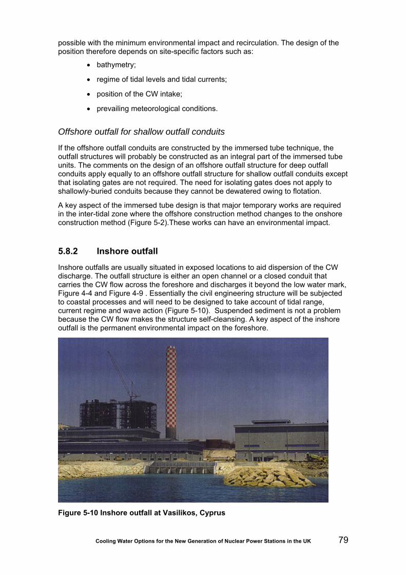
Cooling Water Options for the New Generation of Nuclear Power Stations in the UK 79
possible with the minimum environmental impact and recirculation. The design of the position therefore depends on site-specific factors such as:
• bathymetry;
• regime of tidal levels and tidal currents;
• position of the CW intake;
• prevailing meteorological conditions.
Offshore outfall for shallow outfall conduits
If the offshore outfall conduits are constructed by the immersed tube technique, the outfall structures will probably be constructed as an integral part of the immersed tube units. The comments on the design of an offshore outfall structure for deep outfall conduits apply equally to an offshore outfall structure for shallow outfall conduits except that isolating gates are not required. The need for isolating gates does not apply to shallowly-buried conduits because they cannot be dewatered owing to flotation.
A key aspect of the immersed tube design is that major temporary works are required in the inter-tidal zone where the offshore construction method changes to the onshore construction method (Figure 5-2).These works can have an environmental impact.
5.8.2 Inshore outfall
Inshore outfalls are usually situated in exposed locations to aid dispersion of the CW discharge. The outfall structure is either an open channel or a closed conduit that carries the CW flow across the foreshore and discharges it beyond the low water mark, Figure 4-4 and Figure 4-9 . Essentially the civil engineering structure will be subjected to coastal processes and will need to be designed to take account of tidal range, current regime and wave action (Figure 5-10). Suspended sediment is not a problem because the CW flow makes the structure self-cleansing. A key aspect of the inshore outfall is the permanent environmental impact on the foreshore.
Figure 5-10 Inshore outfall at Vasilikos, Cyprus

Cooling Water Options for the New Generation of Nuclear Power Stations in the UK 80
5.9 Heat dispersion
5.9.1 General process
The warm water from a CW outfall is of lower density than the cooler receiving water and generally forms a surface ‘plume’ in the receiving water. The excess heat in the plume is then gradually dispersed by cooling to the atmosphere. The formation of the plume and process of heat dispersion may be divided into three stages defined by the dominant physical process: near-field, mid-field, and far-field.
In the near-field, the behaviour of the discharge is governed by its initial momentum and buoyancy. The discharge is immediately cooled by entraining the less turbulent ambient water. The extent of cooling achieved by this initial mixing is governed by the design of the outfall. Design variables include:
• total number of discharge ports;
• discharge velocity through each discharge port;
• level of each discharge port relative to the seabed;
• direction of each discharge port relative to the tidal flow.
Another important factor is the temperature rise (ΔT) across the plant, higher values creating more plume buoyancy.
As the plume moves into the mid-field, it has usually reached the surface and the design of the outfall structure has less influence. In the mid-field, dilution of the warm water continues by turbulent mixing at the boundary of the plume. Buoyancy forces also continue to cause horizontal spreading of the plume. The plan shape of the plume is dominated by the ambient tidal current and any wind-driven current. In the mid-field, heat is dispersed partly by mixing and partly by cooling to the atmosphere.
In the far-field, the temperature difference between the plume and the receiving water is so small that buoyancy forces are negligible. The heat in the far-field is dispersed by cooling to the atmosphere and by residual currents. The far-field is sometimes known as the ‘long-term heat field’.
‘Primary’ recirculation occurs if warm water from the mid-field plume is drawn into the CW intake. ‘Secondary’ recirculation occurs if water from the far-field reaches the CW intake. Secondary recirculation is not usually significant.
5.9.2 Methods of predicting heat dispersion
It is possible to predict heat dispersion with a physical model (Figure 4-10) but it is usually quicker and more cost-effective to use a numerical model. Numerical models for water quality and heat field calculations are presented in Section 6.3.4.
5.9.3 Dispersion for UK nuclear power stations
Each discharge plume for the next generation of nuclear power station sites will be designed to meet the requirements of the discharge consent. However, the shape and extent of the discharge plume will be site-specific because it will depend on unique site characteristics such as bathymetry, tidal range, current regime, ecology, meteorology and the detail design of the outfall structure.

Cooling Water Options for the New Generation of Nuclear Power Stations in the UK 81
An indication of the heat dispersion achievable may be obtained from model studies carried out for Sizewell B, CEGB (1986). Figure 5-11 shows the layout of the offshore intakes and outfalls for Sizewell A and Sizewell B. Figure 5-12 shows typical predicted surface temperatures for Sizewell B when the tidal current is flowing from north to south. The plume in Figure 5-12 is typical of heat dispersion in shallow water where the tidal currents are weak. The plume covers a very large area and is attached to the shoreline. In addition the mid-field plume passes directly over the intake for Sizewell A.
In order for the plume not to be attached to the shoreline, the outfall would need to be in deeper water (further offshore) and the tidal currents would need to be stronger. Even if a plume is not attached to the shoreline, it could still be attached to the seabed local to the outfall structure if the ΔT (and hence plume buoyancy) were insufficient.
To ensure efficient plume formation and heat dispersion, the outfall needs to be sited where the depth of water is sufficient to avoid attachment to the seabed. In other words, the natural ambient flow reaching the outfall should be sufficient to feed the entrainment flow demanded by the outfall without distorting the ambient regime.
Figure 5-11 Layout of Sizewell A and Sizewell B
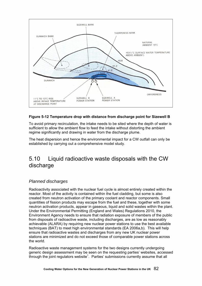
Cooling Water Options for the New Generation of Nuclear Power Stations in the UK 82
Figure 5-12 Temperature drop with distance from discharge point for Sizewell B
To avoid primary recirculation, the intake needs to be sited where the depth of water is sufficient to allow the ambient flow to feed the intake without distorting the ambient regime significantly and drawing in water from the discharge plume.
The heat dispersion and hence the environmental impact for a CW outfall can only be established by carrying out a comprehensive model study.
5.10 Liquid radioactive waste disposals with the CW discharge
Planned discharges
Radioactivity associated with the nuclear fuel cycle is almost entirely created within the reactor. Most of the activity is contained within the fuel cladding, but some is also created from neutron activation of the primary coolant and reactor components. Small quantities of fission products may escape from the fuel and these, together with some neutron activation products, appear in gaseous, liquid and solid wastes within the plant. Under the Environmental Permitting (England and Wales) Regulations 2010, the Environment Agency needs to ensure that radiation exposure of members of the public from disposals of radioactive waste, including discharges, are as low as reasonably achievable (ALARA) by requiring new nuclear power stations to use the best available techniques (BAT) to meet high environmental standards (EA 2006a,b). This will help ensure that radioactive wastes and discharges from any new UK nuclear power stations are minimized and do not exceed those of comparable power stations across the world.
Radioactive waste management systems for the two designs currently undergoing generic design assessment may be seen on the requesting parties’ websites, accessed through the joint regulators website1. Parties’ submissions currently assume that all

Cooling Water Options for the New Generation of Nuclear Power Stations in the UK 83
routine authorised liquid low-level radioactive wastes will be disposed of to the sea or estuaries together with the CW, thereby providing enormous initial dilution. However, the liquid radioactive wastes will first be held in tanks where they will be monitored to ensure compliance with disposal conditions before release to the CW outfall.
Accidental releases
The design of the cooling system has an important role in avoiding accidental releases. Design policy ensures containment by means of a series of physical barriers, so that there is little opportunity for any accidental release of radioactive waste on site to find its way into the CW system. Also, from the CW pumps to the condensers and heat exchangers the cooling water is under positive pressure, preventing ingress in these sections. In a directly cooled system, the only free surfaces where contamination could enter are at the CW pump forebays and the seal pit. With wet towers, the cooling water is under pressure from the CW pumps right up to the sprays inside the towers.
It is of interest to consider whether alternative cooling system designs would lead to different outcomes in the event of radionuclide leakage into the CW circuit. With cooling towers, huge surface areas would need to be decontaminated and there is also a risk of spreading radioactive material over the countryside if the incident were to coincide with high winds and/or damaged or displaced eliminators. On the other hand the contamination would be captured on site within a relatively small volume of water, assuming that the purge were stopped and the reactor shut down.
With direct cooling the contamination would be dispersed in a large volume of water. The type of outfall, whether surface- or bottom-opening, and the local hydrographic conditions are likely to influence the degree of dispersion of any radionuclide particles in the cooling water.
There should be no off-site risk with air-cooled (dry tower) stations since there is no CW discharge and no contact between cooling water and air. With an air-cooled condenser, contamination in the steam circuit (as from a BWR) would be transferred to the large surfaces of the condensers. However, any leaks in the pipework between the turbine and condenser and in the condenser itself would be inward. There is usually a small amount of water-cooling for the auxiliary circuits at air-cooled stations, but this is small volume and retainable.

Cooling Water Options for the New Generation of Nuclear Power Stations in the UK 84
6 Environmental issues associated with cooling
6.1 Effects associated with abstraction
6.1.1 Entrapment, entrainment and impingement
The abstraction of surface water from natural sources means that organisms present in the source water will be drawn into the water intakes. These organisms can include anything from planktonic bacteria and algae to macroinvertebrates and fish; much more rarely, aquatic mammals and diving birds can enter and become trapped. Smaller organisms enter involuntarily, being at the mercy of prevailing water currents. Some larger vertebrate animals enter either because they are already sick or moribund or because they have become disorientated, for example in the dark or in very turbid waters. In some cases, larger predators such as bass (Dicentrarchus labrax) enter opportunistically to feed on whitebait and other organisms that become concentrated within the screenwells of power stations. An experiment at Fawley Power Station (Southampton Water, Hants.) in which large marked rainbow trout were released into the screenwells revealed that they were recaptured in screening samples over the next six months. On inspection, they were found to have gained in weight considerably and had stomachs bulging with small fish (Turnpenny and Holmes, unpublished).
Of organisms entering with a power station’s cooling water, some may enter and leave at will, while others will become impinged on the screen meshes of the filtration system. The remainder will penetrate the screen meshes and enter the main cooling system. The following definitions are commonly used:
• Entrapment - inadvertent entry into the CW system of aquatic organisms caused by the ingress of water; the term implies that the organism is unable to resist capture, owing to poor or no swimming ability, or to failure to detect the water intake.
• Impingement - retention of entrapped organisms on CW intake screens employed to prevent debris entering the CW heat exchangers; to become impinged, organisms must be large enough to be retained by the screen meshes (usually includes e.g. juvenile-adult fish, macroinvertebrates such as shrimps, crabs and large molluscs and marine algae).
• Entrainment - passage of entrapped organisms that penetrate CW screens (typically zooplankton including ichthyoplankton and phytoplankton), via the pumps, heat exchangers and other components of the CW circuit and back to the receiving water. Note: the size break-point between impingement and entrainment depends on the size of mesh openings in the CW screens.
6.1.2 Legal requirement for fish screening
An assessment of legal requirements is described by Turnpenny and O’Keeffe (2005). These arise out of the Salmon and Freshwater Fisheries Act (SFFA) 1975 as amended by the Environment Act 1995. Measures within SFFA Sections 14 and 15 apply solely

Cooling Water Options for the New Generation of Nuclear Power Stations in the UK 85
to the migratory salmonids, Atlantic salmon (Salmo salar) and sea trout (Salmo trutta) and technically apply to waters frequented by these species, a term which is interpreted to require proof that there is a self-supporting population of at least one of these species present, rather than one maintained by stocking.
In order to comply with the Water Framework Directive (WFD), Fish Passage and Screening regulations were proposed. These required the consideration of whether additional measures would be needed to ensure all species of fish are protected rather than just salmonids alone to achieve good ecological status. However, following recent consultation 21, the Better Regulation Executive has put development of these regulations on hold until 2011 due to the potential economic impact on business. It should be noted that, despite these delays, any current and future power station developments would need to adhere to the Fish Passage and Screening regulations in order to comply with the WFD.
In addition the Eels (England and Wales) regulations (2009) came into force in Jan 2010. The regulations reflect European wide concern over the collapse of the European eel Anguilla Anguilla population and require the provision of screening to be considered for eels.
In Natura 2000 sites, operators and developers are required to develop mitigation measures and monitoring programmes to ensure that conservation objectives of the site are not jeopardized.
All of the above fish screening regulations are relevant regardless of whether or not an abstraction licence is required at a site.
6.1.3 Impingement of fish and other biota
Screen mesh sizes
Screen mesh size is the main factor determining the sizes of organisms retained on the CW drum or band screens and those that become entrained. For fish, the size that will be retained by the screen is a function of mesh size and fineness ratio (body length divided by maximum body diameter), the latter being high for elongate, thin fish such as eel or pipefish and low for rotund ones such as lumpfish (Figure 6-1). Older UK power stations of CEGB vintage, including all existing nuclear plants, typically use a mesh of 8-10 mm square aperture. These would retain for, example, bass larger than about 70 mm standard length22 and eels longer than 240 mm. More modern UK stations fitted with purpose-built fish return systems are required to use mesh sizes of 6 mm or less under present guidance (Turnpenny and O’Keeffe, 2005), which would reduce the bass and eel thresholds to around 30 and 100 mm respectively. That is not to say that in either case all fish below these sizes would pass through and become entrained, as some will strike the screen sideways-on and become impinged.
21 http://www.defra.gov.uk/corporate/consult/fisheries-legislation/ (viewed 22/02/09) 22 Standard length is the length from the tip of the snout to the caudal peduncle. It is commonly used in power plant studies, rather than total or fork length, as tail fins are often damaged as a result of screen handling on older non-fish-friendly screens.

Cooling Water Options for the New Generation of Nuclear Power Stations in the UK 86
Figure 6-1 Mesh size curves for screening fish of different body shapes (from Turnpenny and O’Keeffe, 2005, after Turnpenny, 1981)
Finer mesh sizes are more common in continental Europe. French nuclear stations operated by EDF favour a three to four mm plastic mesh, which reduces the entrained component to smaller plankton, including fish eggs, larvae and postlarvae. The use of finer meshes may or may not be more protective of fish, depending on the comparative survivability of the impingement and entrainment processes, and in the case of impingement, whether the impinged material is returned to the source water body. These aspects will be discussed further in this and following sections.
Fish inundation and the process of fish removal by screens
The process of impingement, once within the screenwell, is rapid for non-motile or weakly swimming organisms but may be protracted for many fish. The natural reaction of fish held in a current is to attempt to swim against the flow. Investigations of fish impingement patterns in tidal systems suggest that even small fish such as sprats (Sprattus sprattus) are capable of active avoidance of impingement for several hours, usually until the water level in the screenwell drops and higher velocities force them onto the screen meshes (Turnpenny and Utting, 1981). This behaviour increases the peak loading of fish onto the screens leading up to the low water period and has been a key factor causing screens to block with winter sprat inundations, notably at Sizewell A and the Dungeness stations. One CEGB proposal involved the installation of mesh baffles within the screenwell to reduce the volume of water accessible to fish and thus force them quickly onto the screens, thereby smoothing out the screen loading over the tidal cycle. This was never implemented.
Sudden sprat inundations are caused when large overwintering schools move close inshore. These remain an operational risk at eastern and south-eastern UK open coastal sites. Historically, clupeid inundations, including herring (Clupea harengus), have also affected sites on Scottish east-coast estuaries such as Longannet and Kincardine Bridge. Other pelagic species may have a similar potential to cause problems and recent observations of large concentrations of anchovy (Engraulis encrasicolus) eggs and larvae off the Blackwater Estuary on the south-east coast of

Cooling Water Options for the New Generation of Nuclear Power Stations in the UK 87
England are noteworthy (Andy Payne, Cefas, personal communication 2008 surveys). This species is currently at the northern end of its distribution at this latitude.
While drum screens are rotated continuously, and therefore lift out debris relatively soon after its impingement on the screen, this is not always true of band screens. Band screens have many articulating parts and therefore inherently wear out more quickly, especially in abrasive, sediment-loaded waters. To extend band screen life, they are often rotated only for brief periods after the accumulation of debris on the screen face has caused partial blockage and a pressure differential is detected by instrumentation. Consequently, fish may be pinned against the screens for several hours before removal.
Band and drum screens usually have more than one speed setting. Normal operation uses the lower speed settings to conserve the life of the bearings, tripping to higher speeds only during periods of high debris loading.
Material is removed from drum or band screens, as the ascending face of the screen emerges through the water surface, by a ledge or ‘trash elevator’ onto which they slide or fall (Figure 6-2) Unless specifically designed for fish recovery, these elevators are normally open-ended and free draining, so that biota come into hard contact with the screen structure. This exacerbates injury risk. While this may be immaterial when organisms are destined only for landfill disposal, it becomes an important consideration where screens not originally designed for safe fish handling are subsequently adapted for fish return.
Figure 6-2 Bandscreen panel fitted with six-mm square woven stainless-steel mesh. The trash elevator is in the form of a narrow ledge which does not retain water and is unlikely to properly retain larger or writhing fish such as eels.
Quantities and types of organisms impinged at UK stations
The value of power station screens as fish sampling tools was recognised in the 1960s when biologists first saw fish returning to the tidal Thames through monitoring the contents of trash baskets (Wheeler, 1979). This prompted university biologists to do the same elsewhere, for example on the Severnside and South Wales stations (Claridge and Potter, 1985; Caridge, Potter and Hardisty, 1986). From the 1970s, the National Rivers Authority began regular sampling of fish from West Thurrock power station to
Trash elevator

Cooling Water Options for the New Generation of Nuclear Power Stations in the UK 88
monitor for disease and contamination (see Power, Attrill and Thomas, 2000) and continued until the station’s closure in 1992. MAFF Directorate of Fisheries Research (DFR – now Cefas, Lowestoft) also recognised the value of this method to assess year-class-strength in bass (Dicentrarchus labrax), principally at Oldbury-on-Severn and Kingsnorth power stations (Pickett and Pawson, 1994), to cover west and east coast sub-stocks respectively. Meanwhile, by the mid-1970s, the CEGB was concerned by legal actions being launched against power companies in the USA. A successful prosecution of Indian Point power plant on the Hudson River (New York) in 1972 led to a fine of US$1.6 million resulting from the capture of large numbers of small fish in power plant cooling water screens (Langford, 1983). The CEGB established its own programme of fish impingement studies via the staff of its Fawley Marine Laboratory. As the CEGB was a publicly owned body, many of these were carried out in collaboration with MAFF DFR (see Langford and Utting, 1977; Turnpenny et al, 1988).
Joint CEGB/MAFF investigations carried out at Sizewell A Power Station as part of the Sizewell B pre-application work still provide the benchmark for fish impingement survey design and analysis (Turnpenny and Taylor, 2000). Fish impingement became one of the key non-nuclear environmental issues for Sizewell B, after local fishermen objected to catches of mainly undersized fish by the A-station. A comprehensive assessment was therefore undertaken, the first fully quantitative one of its kind. The study collected complete catch over 24-hour periods from all operating screens on 40 dates per year, with ten randomly selected dates per quarter. This ‘systematic randomised’ sampling was used to obtain representative samples. Taking 24-hour samples eliminates diurnal and short-term tidal cycle influences, while randomisation takes out longer-term tidal cycle effects and any systematic tendency in terms of CW abstraction pattern. The number of 24-hour samples required may vary between sites according to variability and required statistical power, but experience shows this to be a good default. More details of the methods and findings from the studies carried out at Sizewell A and B can be found in Turnpenny and Taylor (2000).
The sampling method for such studies is straightforward. Usually, the trash baskets are cleared and net liners are placed inside at the start of the sampling period. Fish and other biota are then removed at intervals and sorted to species, identified, weighed and measured as required (Figure 6-3). Samples may be retained for laboratory analysis of pesticide residues, stomach contents and so on.
Figure 6-3 Sorted sample of fish collected from power station screens (left). Catches at saltwater sites typically contain a wide range of species but are often dominated by pelagics, such as sprat and herring. The bulk of the catch is often made up of juveniles or smaller species of under 20 cm in length, although certain locations and intake designs can put larger fish at risk (right).

Cooling Water Options for the New Generation of Nuclear Power Stations in the UK 89
Indicative catch rates by impingement for British and some Channel-coast French sites were given by Turnpenny and Coughlan (2003) and ranged from a few tonnes per year to the highest recorded value of 240 tonnes per year at Gravelines in France. More useful are figures for the catch per million cubic metres of CW flow, which take out the effect of plant size. These still show order-of-magnitude differences between sites, which are due to factors such as intake design and locality. The highest impingement rates tend to occur at sites on the open coast, such as Sizewell and Dungeness, owing principally to the abundance of pelagic fish which dominate the catches in these areas. However, there are always exceptions, such as Wylfa, sited on the rocky north-west point of Anglesey, where catches are exceptionally low.
Figure 6-4 Coarse screen blocked by fouling
Figure 6-5 Estimated annual total quantities of fish impinged at UK estuarine and coastal power stations (Turnpenny and Coughlan, 1992)

Cooling Water Options for the New Generation of Nuclear Power Stations in the UK 90
Government plans in the 1980s to expand nuclear generation following the successful licensing of the Sizewell B PWR led to an urgent need to screen coastal sites for new nuclear build. The scientific approach to fish impingement at Sizewell had proved successful in allaying the fears of commercial fishermen and it was decided the same approach should be adopted for other proposed nuclear sites. This was straightforward at existing nuclear sites where screens could be sampled directly, but would prove more difficult at greenfield sites. To bridge this gap, CEGB Fawley Marine Laboratory developed an expert system model capable of predicting order-of-magnitude impingement rates by analyzing patterns observed at operating sites. PISCES (Prediction of Inshore Saline Communities Expert System) enables the numerical abundance, seasonality, age composition and biomass of the most common impinged fish and crustaceans to be predicted for any British coastal or estuarine site, given basic information such as location, salinity, substrate types and adjacent habitat types. It is based on some twenty years of research into impingement rates at coastal power stations, which has led to the development of ecological rule-sets that enable predictions for unsurveyed sites. PISCES has been widely used in relation to new plant applications in British and northern European (Dutch and French) power stations, either in the absence of or to supplement data. PISCES has shortcomings, being based on old CW intake designs which would not conform to modern design requirements, but a new version is currently being developed by Pisces Conservation Ltd (Seaby and Henderson, 2009).
A variety of crustaceans is usually found in screen samples, including crabs, shrimps and prawns of various kinds. At Sizewell A, for example, Whitehouse (1986) estimated an annual impingement catch of the brown shrimp, Crangon crangon, of 16 tonnes. At Hinkley Point, catches regularly include quantities of C. crangon, along with the pelagic prawn, Pasiphaea sivado, and the edible prawn, Palaemon serratus (Henderson and Holmes, 1982). Generally, crustaceans are resistant to handling and where FRR systems are provided (Section 6.1.6), the majority can be returned unharmed.
The largest invertebrate species impinged on power station intake screens are cephalopod molluscs (squid and cuttlefish). The impingement and population dynamics of cephalopods was studied at Fawley Power Station, Hampshire, between 1978 and 1981 by Bamber (1981). Five species were recorded, three of which, Loligo vulgaris, L. forbesi and Sepiola atlantica were either too infrequent or not adequately represented for analysis owing to sampling selectivity. The cuttlefish Sepia officinalis (a species of commercial value) and the small squid Alloteuthis subulata were common and their local life histories were analyzed. Impingement was seasonal, occurring between April and the onset of winter, when temperatures were above 10ºC: adults arrived during the early phase, to breed and then die (both species being annual), to be replaced by their young as they grew on, until finally migrating offshore as water temperatures dropped. The quantities involved in impingement – 0.24 tonne per year – were not perceived to be a problem to power station operation, or to be significant to local cephalopod stocks. Most of the impinged biomass was from post-breeding, senescent adults.
Injuries and survivability of impingement on traditional drum and band screens
The proportion of fish, crustacea and other organisms surviving impingement was practically zero at almost all UK estuarine and coastal power stations prior to the 1970s, as it was common practice to collect all the screen backwashings in trash baskets and dispose of them to landfill; this remains the practice at some. At a few stations (such as Bradwell, Sizewell A), the material was macerated and discharged back to sea, at least in this way putting some material back into the marine food web.

Cooling Water Options for the New Generation of Nuclear Power Stations in the UK 91
Indirectly-cooled inland stations more commonly put backwashed material back to the river. In cases where material is returned to the source water, the practice may require a discharge consent from the Environment Agency. Improved fish protection technology at newer stations has greatly reduced the need for waste disposal from backwashings (see Section 6.1.3).
A number of studies have investigated survival rates of fish collected from CW screen backwashes. Such studies are usually done to assess the benefits of returning the fish to the wild. Depending on the CW intake arrangement, fish collected at this point will normally have experienced a number of possible stress factors, as a result of:
• prolonged swimming ahead of the intake coarse screens to avoid entrapment;
• passing through the intake opening and any canal or culvert leading into the plant, particularly in deep tunnels where fish may experience rapid pressure fluxes in the ascending and descending limbs;
• turbulence in the forebay and screenwells;
• biocide toxicity (normally applied upstream of the screening plant);
• prolonged swimming to avoid becoming impinged on the drum or bandscreens;
• being pinned on the screens prior to removal (may be for hours in the case of band screens that only rotate in response to increased hydraulic head-loss);
• repeated recycling through the screenwell when screen elevators (also known as ‘troughs’ or ‘buckets’) are inefficient at retaining fish: especially a problem for large fish or sinuous fish such as eels;
• exposure to high-pressure backwash sprays;
• prolonged retention in screen hoppers and launders caused by inadequate backwash spray flow or blockage of paths by accumulating weed and debris.
The test protocol usually involves collecting fish in nets or baskets placed beneath outlets from the screen launders, separating, identifying and counting live versus dead fish at the time of removal of fish from the launders. This is followed by monitoring survival rates of live fish over the subsequent hours or days. All fish are also examined for external injuries, such as scale loss, fin damage, flesh wounds and eye injuries, then for internal injuries such as swimbladder rupture or haemorrhaging.
A number of injury and survivability studies are known to have been carried out at UK power stations, although data have generally not been published and are not easy to track down. A brief study carried out at Fawley Power Station (Hampshire), which has drum screens that have no modifications to make them fish-friendly, revealed that over 90 per cent of fish exhibited external signs of injury. Commonest symptoms were fin damage (splitting or haemorrhaging), scale loss and eye damage (Turnpenny, 1992). Larger fish, which can fall off the screens many times before being successfully removed, will often suffer abrasion sores, gashes or, in the case of eels, spinal fracture (Figure 6-6).

Cooling Water Options for the New Generation of Nuclear Power Stations in the UK 92
Figure 6-6 Examples of fish injuries caused by impingement. Left: bleeding into the eye is common as a result of exposure to pressure change. Right: an eel with spinal fracture.
Some studies have included dissection to identify swimbladder rupture, a symptom caused by rapid depressurisation, which can cause the swimbladder gases to expand and tear the surrounding tissue. A similar effect is seen in fish that have passed through hydroelectric turbines (Turnpenny, 1998). Gadoid fish such as whiting (Merlangius merlangus) and pout (Trisopterus luscus), which regulate swimbladder volume by vascular exchange (known as “physoclists”) as opposed to by gulping and venting air via the gut (“physostomes”), are particularly susceptible. At Sizewell B, more than a third of whiting and pout collected from the screens were found to have ruptured swimbladders. While swimbladder injuries will heal within a few days (Turnpenny et al. 1992), loss of swimbladder function in the meantime may affect functions like buoyancy, balance and hearing, potentially putting fish at greater risk of predation. Station designs most likely to cause pressure effects of this kind are those in which the CW tunnels descend deep below the water surface, so that fish are exposed to rapid depressurisation as they are brought back up to the surface and out onto the screens. Under these conditions, outgassing of the body fluids can also occur, causing symptoms similar to “the bends” in humans.
Fish survival rates post-impingement have generally been estimated only following some design modification to improve survivorship. Turnpenny (1992) reviewed findings from a number of fish return systems in Europe and the USA, which revealed marked distinctions between categories of fish. Pelagic fish, often with ‘deciduous’ scales, in normal life will avoid contact with the bed and hard structures and are unlikely to survive impingement. Demersal fish are more robust and can usually cope with some physical contact but can be susceptible to swimbladder rupture; these have a moderate chance of survival. Benthic species, those normally living in contact with the sea or river bed, are physically robust and lack a significant swimbladder, and generally have the best survival rates (Table 6-1). Monitoring of post-impingement fish and crustacean survival rates was carried out routinely between 2000 and 2003 by Clough et al. (2003) as part of post-commissioning studies at Shoreham power station (W. Sussex). Overnight (16-24 hour) survival rates averaged 80 per cent for C. crangon and 76 per cent for prawns (Palaemon serratus). The system at Shoreham comprises a standard Brackett-Green bandscreen with traditional fish buckets.
Best practice in design of drum and band screen systems for fish return is discussed further in Section 6.1.5.

Cooling Water Options for the New Generation of Nuclear Power Stations in the UK 93
Table 6-1 Typical fish survival reported from studies of drum or band screens with simple modifications for fish return (Turnpenny and O’Keeffe, 2005).
Fish group Survival rate 48 hours after
impingement PELAGIC
e.g. herring, sprat, smelt
Less than 10%
DEMERSAL e.g. cod, whiting, gurnards
50-80%
EPIBENTHIC e.g. flatfish, gobies, rocklings,
dragonets, and crustacean
More than 80%
6.1.4 Entrainment of fish and other biota
Measurement of entrainment rates
Compared to impingement, fewer studies of fish entrainment rates at UK power stations have been reported. Entrainment is less visually obvious than impingement and sampling techniques are more difficult. For fish species, losses of eggs and fry are also thought to be less important to maintenance of the stock than the capture of more mature fish, which represent a higher value to the population. However, development in recent years of effective mitigation techniques against impingement rates and mortalities now makes losses from entrainment a bigger part of the environmental impact of CW abstraction.
Entrainment rates are measured by intercepting a sample of CW flow with fine-meshed plankton nets, typically of 0.275-0.5 mm mesh-size. This is achieved by:
• a plankton net placed in part of the intake flow (for example in the forebay, where the degree of turbulence allows);
• drawing water from a tapping on the pressure side of the main CW pumps or screen-washwater pumps (which usually draw from the screenwells) and passing it through a suspended plankton net;
• using a purpose-built powered plankton-sampler lowered into the forebay (Coughlan and Fleming, 1978).
When a power station is yet to be built and there are no historical data from a previous or existing plant, prediction of entrainment impacts usually relies on conducting plankton surveys in the vicinity of the proposed intake point, perhaps also backed up by sampling a reference site that is expected to remain undisturbed after the development. Standard plankton-sampling methods commonly involve oblique or undulating hauls to ensure that most of the water column is sampled. This overcomes the risk of missing populations that may be found only at particular depths, for example where the water column is stratified owing to temperature or salinity effects. Some types of power station intake structure abstract selectively from deeper layers to reduce recirculation of the buoyant plume and therefore do not draw in a sample representative of the whole water column. This may explain observations reported by Coughlan and Davis (1980)

Cooling Water Options for the New Generation of Nuclear Power Stations in the UK 94
for Bradwell Power Station (Blackwater Estuary, Essex) and Dempsey (1988) for Fawley Power Station (Southampton Water, Hampshire), which in both cases show concentrations of entrained ichthyoplankton to be an order of magnitude less than those found in the open water. In any event, despite the tidal rise and fall at coastal or estuarine sites exposing the CW intake orifice to most of the vertical range of the water column, it is rare that the CW water will be abstracted from the full vertical range.
A key factor in the success of these sampling methods is achieving adequate sample volumes and good diel and seasonal coverage. It is now common for the Environment Agency to attach monitoring conditions to new abstraction licences and this has led to the need for sampling protocols for, inter alia, measurement of entrainment rates. While no formal protocol has been established, developing practice at new sites has been to specify 24-hour sampling periods using sample flow rates of 10 to 25 ls-1, where these flow rates are practically achievable. This appears to provide good representation of fish taxa, which are notoriously patchy within the plankton and may otherwise be missed. Sampling is typically carried out at least monthly (sometimes weekly during periods of peak ichthyoplankton activity) all year round, or for a six-month period from spring to late summer, outside which fish leave the planktonic phase.
Other types of plankton entrained will include temporary (meroplankton) and permanent (holoplankton) planktonic taxa, including molluscs, crustaceans and other invertebrates, as well as phytoplankton. Holoplankton are commonly more abundant than ichthyoplankton, and adequate samples can be obtained by the methods outlined above or from much smaller “bucket” samples. However, these species show marked (and well-documented) seasonality in their abundance in the plankton. Meroplankton include larvae of a wide range of taxa which have a sessile, benthic or pelagic adult life; many of the invertebrate meroplankters are of commercial significance (larvae of commercial species of shellfish and crustaceans). These species also show constrained seasonality in their presence in the plankton. Again, it must be appreciated that these taxa are patchy and are stratified in the water column.
Entrainment at UK inland stations
Studies at inland stations have been limited and confined to investigation of larval fish entrainment. A brief study at the indirectly-cooled Didcot A power station was carried out by Aston and Fleming (1992) and was the first of its type in the UK. The station was estimated to entrain around 1.9 x 10⁶ fish fry annually for a CW abstraction rate of 2.4 m3s-1; however, this value did not fully take into account the seasonal variability of entrainment and was therefore considered to be an overestimate.
A subsequent investigation at Ratcliffe-on-Soar Power Station (CW flow 2.08 m3s-1) on the River Trent undertaken by Smith (1998) between 1994 and 1997 revealed a strongly seasonal pattern of fish entrainment. This was characterized by influxes of newly hatched ‘pinhead’ fry of coarse fish during the spring and early summer months following spawning, quantities declining throughout the summer as fry numbers in the river decreased owing to high natural mortality rates. Greater ability of fish to avoid entrapment is likely to have been a factor as the season progressed and fish grew larger. The overall loss rate of fish averaged 3.45-7.98 x 10⁵ fry per annum over the three years. Dominant species were roach (Rutilus rutilus), bream (Abramis brama), bleak (Alburnus alburnus) and chub (Leuciscus cephalus). Smith converted these numbers to equivalent adult values (EAVs) which amounted to 2,290 adults per annum (see later in this section for a fuller description of the EAV methodology).
Studies of entrainment patterns at other types of inland water-intake consolidate the picture from power station studies. Turnpenny (1999) carried out a desk study of the combined coarse-fish fry entrainment potential of all raw water intakes on freshwater

Cooling Water Options for the New Generation of Nuclear Power Stations in the UK 95
Thames (nine in total) based on an extrapolation of data from only one of the intakes. The study concluded that substantial numbers of young coarse fish were likely to be lost to the fishery. As a worst case, if all the intakes operated at maximum licensed capacity (around 80 m3s-1 combined capacity), the loss of fish to entrainment could amount to the equivalent of up to 45 per cent of the adult standing stock of the Lower Thames. A subsequent two-year field study carried out in 2006-7 (Turnpenny et al, 2008) showed that even this figure may have been low and potential losses at maximum licensed capacity could amount to 61 per cent of the total adult stock.
All of these studies showed common features, which can be summarized as follows:
• Proportional losses of stock to entrainment are related to the abstraction
flow; cumulatively along a river reach they can represent a substantial impact on numbers of fry available to recruit into the adult fishery.
• Catch rates are highly seasonal, peaking in the spring, shortly after spawning, but extending through the summer months.
• Entrainment rates tend to be positively correlated with river flows and are highest at night, corresponding with fry migration studies on large river systems which show that fry drift or migrate downstream principally under these conditions as part of their natural distribution mechanism (Pavlov et al. 1978).
Entrainment at UK estuarine and coastal stations
Survivability of entrainment in once-through cooling systems In the absence of reliable evidence to the contrary, it has often been assumed that all plankton passing through a power station’s CW circuit will be killed. This view is central to US EPA thinking and policy on entrainment impacts and is a key reason why US assessments of the impact of direct cooling systems on ecosystems yield substantial estimates of harm. However, there is convincing evidence from UK studies that survivorship in various taxa, including fish, other zooplankton and phytoplankton can be high. Moreover, as survivorship has been shown to be influenced by aspects of the design and operation of once-through cooling water systems, it is clear that one conclusion will not hold for all stations and that there may be opportunity for increasing survivorship through plant design and operational controls.
The belief that cooling circuits act like vast sterilizers stems from the fact that plankters are subject to a number of potentially lethal stressors during passage. These include:
• The same mechanical and hydraulic stresses in the intake line and forebay and screenwells as impinged organisms.
• More protracted exposure to potentially toxic biocide levels throughout the CW circuit.
• Rapid temperature increase through and beyond the condenser boxes.
• Changes in hydrostatic and hydrodynamic pressure caused by differences in level and by pumping.

Cooling Water Options for the New Generation of Nuclear Power Stations in the UK 96
• Hydraulic shear stress, turbulence and abrasion associated with passage through screens, culverts, small-bore condenser tubes and other pipework.
Three main approaches have been used to study the viability of organisms following exposure to entrainment stressors:
• power-plant-based entrainment monitoring, where live:dead ratios are compared between the CW plant inlet and outlet points (see Coughlan & Fleming, 1978; Coughlan & Davies, 1983; Dempsey, 1983);
• laboratory-based cooling-circuit simulation studies (see Bamber et al. 1994; Bamber & Seaby, 2004; Kennedy et al. 1974; Beck et al. 1975);
• laboratory dose-response studies using chlorine and temperature combinations.
Power plant-based entrainment monitoring In the UK in the 1970s, studies were undertaken to examine the survival of entrained phytoplankton and zooplankton at five coastal/estuarine power stations: Fawley (Hampshire), Sizewell A (Suffolk), Kingsnorth (Kent), Bradwell (Essex) and Heysham 1 (Lancashire) (Coughlan & Davies, 1983). Subsequently, phytoplankton productivity at Fawley Power Station was measured to estimate the survival of entrained organisms (Davies, 1983). Seawater (10 litres per replicate) was sampled from the intake and outfall and incubated with the radioactive carbon isotope C14 for three hours under standard temperature and light conditions. The rate of C14 fixation was compared between intake and outfall samples to give an estimate of the survival rate of phytoplankton passing through the CW system. Phytoplankton productivity fell by 50-60 per cent having passed through the CW system under routine conditions at Fawley Power Station (ΔT 8-10°C, <0.2 mgl-1Cl at outfall). The main cause of mortality was chlorine concentration. Experimentally varying the dosed chlorine level allowed the effect of chlorine toxicity to be assessed. The main cause of mortality (assuming that the rate of C14 fixation was a valid proxy of survival) was concluded to be exposure to the biocide.
Figure 6-7 Effect of chlorine concentration on carbon fixation by phytoplankton at Fawley Power Station, Hampshire (Source: Davis, 1983)

Cooling Water Options for the New Generation of Nuclear Power Stations in the UK 97
Inhibition of photosynthesis by phytoplankton has also been observed in chlorinated cooling water by researchers in estuarine water (Hamilton et al. 1970) and seawater (Carpenter et al. 1972; Khalanski, 1977).
Davis (1983) sampled seawater from the intake and outfall at Fawley Power Station (Hampshire, UK) and measured the temperature, salinity and primary productivity in all samples. The concentration of total residual chlorine was determined in all outfall samples. Primary productivity was reduced in the presence of chlorine, with a 96 per cent reduction at a concentration of one mg l-1. Where final water temperature reached up to 23 °C, productivity was observed to increase by up to 15 per cent. Where final water temperatures exceeded 23 °C the productivity decreased by up to 11 per cent. No correlation was found between ΔT and productivity (Davis, 1983).
Two trials were carried out in the absence of chlorination and temperature rise (Davis, 1983), allowing an assessment of mechanical damage effects to be made; in both cases, primary productivity increased to the same order as that observed for the temperature rise. The change in productivity observed here was linked to the heterogeneity in sampling and observations reflecting the views of other researchers (Flemer & Sherk, 1977) that the mechanical effects of entrainment on phytoplankton are too small to be detected in field studies (Davies, 1983).
Davis (1983) acknowledged the wide variation in reported effects of power plant CW chlorination on the primary productivity of entrained phytoplankton; he attributed the variation to differences in location of the power plants, and variations in phytoplankton populations, water quality, operating conditions and sampling and/or experimental techniques where the studies took place.
Davis (1983) recognised other limitations in his study, such as holding phytoplankton samples in the chlorinated water for up to three hours post-sampling. In reality, on return to the sea, chlorine concentration becomes progressively lower as the discharge water becomes diluted. This was not achieved under laboratory holding conditions. Despite this, Davis was able to conclude that phytoplankton productivity was not as inhibited by chlorination as previous studies had suggested (Carpenter et al. 1972), a finding in agreement with Hirayama and Hirano (1970). Thus, given the unrealistically high chlorine concentration during the holding situation in the study by Davis (1983), inhibition of phytoplankton productivity may even be lower in reality.
Survival studies of zooplankton at the power stations mentioned above revealed differences in survival rates depending on geographical location, that is, whether the power stations were located in estuaries or on the open coast (Coughlan and Davis, 1983). In their study, Coughlan and Davis (1983) collected zooplankton from 200-litre volumes of water sampled with a pump sampler designed to minimize sample damage. Their design allowed the plankton to be filtered from the water prior to the water being drawn into the pump. Samples were taken from the power station intakes and outfalls (Coughlan and Fleming, 1978a).
Vital staining techniques to analyze entrainment survival were first tried by Heinle (1976) studying copepods at three power stations in the USA. On collection, a vital stain, Neutral Red, was added to the samples; this stain is only absorbed by live organisms (Fleming and Coughlan, 1978). This technique is considered more reliable and less time-consuming in the field compared with monitoring the motility of sampled zooplankton (which must be assessed immediately upon capture) as a means of establishing mortality (see Dressel et al. 1972). Heinle (1976) found poor replication and inconsistencies attributable to stratification of the plankton in the sampled water; numbers of organisms per sample were often below 10. Percentage survivals, measured by those individuals taking up the vital stain, were generally high at both intake and discharge (mostly above 80 per cent) with some examples of reduced survival at the discharge during chlorination. However, quantification was not practical.

Cooling Water Options for the New Generation of Nuclear Power Stations in the UK 98
The overall conclusion was that sample sizes (hourly one-litre samples) were inadequate, despite the effort and funding such a programme required. As copepods (holoplanktonic Crustacea) are typically abundant in zooplankton samples, adult calanoid copepods were the organisms monitored in the study by Coughlan and Davis (1983), using pumps to obtain larger sample volumes. One-hour post-collection and staining, the samples were preserved and could later be analysed for live (red) and dead (non-red) individuals. A series of studies on zooplankton survival at French coastal power stations, reported by Khalanski (1978), gave a range of results from increased densities of zooplankton at the discharge (vital-staining tests), no differential survival (post-entrainment incubations), holoplankton mortalities of between 30 and 70 per cent (asynchronous post-entrainment densities), and 100 per cent mortality of sprat eggs and 17 to 61 per cent mortality of sole eggs attributed predominantly to mechanical shock.
Copepods from estuarine environments incurred greater mortality than those from open coastal locations. Mortality rates were considered in relation to seawater quality (poorer in estuaries) and chlorine concentration (Coughlan and Davis, 1983). Although mortality increased greatly with chlorine concentration, compared with phytoplankton it was much lower and under standard operating conditions (ΔT 8-10 °C, <0.2 mg l-1 Cl at outfall) the survival of adult calanoid copepods in the zooplankton was above 90 per cent (Figure 6-8; Turnpenny and Coughlan, 2003).
Figure 6-8 Percentage mortality of adult calanoid copepods within one hour of entrainment under various chlorination regimes at four different UK power stations (Source: Coughlan & Davis, 1983)
Laboratory-based studies The problem with power station-based studies is that the range of taxa available for assessment is largely a matter of chance: while it is feasible to study copepods or phytoplankters in general, as some will invariably be present, no one species can be guaranteed. Further, owing to the sparseness of some species, including commercially important meroplankton, it may be impossible to sample adequate numbers even if they are known to be present at that time and place. Such studies are only able to test
Cooling Water Options for the New Generation of Nuclear Power Stations in the UK 99
the effects of the totality of entrainment, although Coughlan and Davis (1981) were able to vary the biocidal chlorine dosing levels during some of their studies.
Laboratory-studies in theory offer the advantage of controlling the entire experimental entrainment process, including the test animals (guaranteeing results),and stressors. The apparatus should have a practical advantage, as the flow can be passed through a single (full-length) condenser tube, so that a relatively small and manageable flow of water is used. This means that as few as thirty to fifty individuals (eggs, larvae and so on) can be tested per experimental run, with 100 per cent recapture in the collecting vessel, and no significant handling damage.
Early attempts at experimental assessment of entrainment took too simplistic an approach to offer useful interpretation. Poje et al. (1981) undertook experiments on estuarine fish and arthropods using a condenser-tube simulator; unfortunately, their apparatus was unable to generate the complex pressure profiles characteristic of power station cooling-water systems.
Kwik and Dunstall (1985) cultured zooplankters in conditions of thermal shock, mimicking entrainment stresses; they generally found that survival was of the order of 90 per cent as long as the test temperature did not exceed 29.5°C, irrespective of ΔT. Obviously, this does not mimic normal operating conditions as only thermal stress was tested.
Schubel et al. (1976) exposed eggs and larvae of three fish species from the Chesapeake Bay region (blueback herring, Alosa aestivalis; American shad, Alosa sapidissima; striped bass, Morone saxatilis) to simulated ΔT effects by simply immersing small pots containing the test animals in water baths at different temperatures for between four and 60 minutes, returning them to ambient temperature water-baths for cooling to background temperature (60-300 minutes). They found that ΔTs of 7 and 10°C did not significantly affect hatching success of any species, while a ΔT of 15°C significantly reduced hatching success of both blueback herring and American shad; only striped bass larvae could withstand ΔTs up to 10°C with no significant increase in mortality. A ΔT of 20°C resulted in near total mortality of eggs and larvae of all three species. Despite finding that the fish eggs were apparently more tolerant of ΔT effects than were the larvae, most response patterns were found to be “complicated”. Of course, such buffered thermal impacts do not reflect actual conditions during entrainment faithfully.
Other studies in Europe involved simple tolerance tests of stressors (mainly temperature) in culture. These studies were numerous (being easy to set up), inconclusive and were of limited application to the real entrainment situation (see review by EDF, 1978).
Simulations were conducted in the USA using condenser tubes to assess the mechanical stresses of entrainment (see Cada et al. 1981; review by Jinks et al. 1981). Large differences were observed between species in their response to pipe and condenser passage and, for most species, short-term mortality associated with passage, estimated to be under five per cent, increased with increasing ΔT and/or pumping rate. However, there was no significant difference in survival between test and control organisms.
An Entrainment Mimic Unit (EMU), a laboratory simulator (Figure 6-9), was developed by Fawley Aquatic Research Laboratories (FARL) in the 1990s to assess entrainment survival (Bamber et al. 1994). This apparatus was superior to its predecessors in that it was able to mimic the levels and range of stressors found at power stations; these stressors could be varied individually and applied alone or in combination, allowing the distinction of their effects separately, synergistically or antagonistically.

Cooling Water Options for the New Generation of Nuclear Power Stations in the UK 100
Figure 6-9 Schematic of FARL Entrainment Mimic Unit (EMU) (after Bamber et al. 1994)
Computer-controlled solenoid and mechanical valves allowed the replication of a complex pressure profile (normally that of a coastal direct-cooled PWR), while controlling the timing of hot-water delivery to allow a range of ΔT. Effects of antifouling “chlorination” were tested by introducing sodium hypochlorite at a range of test dose levels. The mechanical stresses of entrainment (physical abrasion, collisions and so on) were an inherent feature of the apparatus and as such uncontrollable. Test conditions ranged around typical coastal power station stress-levels of 0.2 ppm of Total Residual Oxidant (TRO) and 10ºC ΔT, normally between zero and one ppm and between 0 and 15ºC.
Tests were conducted on the planktonic stages of a range of species, including meroplanktonic eggs and/or larvae of commercial crustaceans (common shrimp and lobster), commercial fish (sea-bass, Dover sole, turbot), a commercial mollusc (Pacific oyster), fouling species (two barnacles, common mussel) and the holoplanktonic copepod Acartia tonsa. A summary of entrainment mortality of these species under “normal” power station levels of stressors is given in Table 6-2, based normally on the condition of specimens 24 hours after entrainment.

Cooling Water Options for the New Generation of Nuclear Power Stations in the UK 101
Table 6-2 Percentage entrainment mortalities of a range of planktonic species under “normal” power station levels of stressors, interpolated from series of EMU experiments (data from Bamber & Seaby, 1993; 1995a,b; 2004; Bamber et al. 1994).
Species Stage Mortality at 0.2 ppm TRO and 10ºC ΔT (%)
Crustacea Acartia tonsa (Copepoda) Adults 20
Crangon crangon (common shrimp) Larvae 25 Homarus gammarus (lobster) Larvae 8 Elminius modestus (barnacle) Nauplii 0
Fish Dicentrarchus labrax (sea bass) Eggs 46 Dicentrarchus labrax (sea bass) Larvae 44
Solea solea (Dover sole) Eggs 7 Solea solea (Dover sole) Postlarvae 92 Psetta maxima (turbot) Eggs 7 Psetta maxima (turbot) Larvae 70
Mollusca Crassostrea gigas (Pacific oyster) Larvae 95 Mytilus edulis (common mussel) Larvae 0 Mytilus edulis (common mussel) Spat 35
What is striking is the wide range of effects between major animal groups, between species and between different life-stages of the same species.
The pressure cycle caused a significant mortality in the copepod Acartia tonsa, Pacific oyster larvae, and, combined with the ΔT, inhibited hatching of the flatfish eggs, but affected no other taxa tested.
The physical stresses of entrainment were the only factors to cause significant mortality in turbot larvae (usually loss of yolk-sac) and lobster larvae (usually loss of abdomen), but on no other taxa tested.
The residual from chlorination (TRO) at around 0.2 ppm contributed to the mortality of sole post-larvae, sea bass larvae, mussel spat, Pacific oyster larvae, Crangon larvae and Acartia adults, but had no significant effect on any other taxon tested.
The thermal stress was resolved into two factors: the ΔT caused significant mortality to sea bass eggs and larvae (with an evident synergism with TRO), and contributed to significant mortalities of flatfish eggs and sole post-larvae; the actual enhanced temperature (ºC) increased the mortality of Crangon larvae in response to TRO in an evident synergism.
The results show that most individuals of most taxa (other than flatfish larvae/post-larvae and Pacific oyster larvae) survive entrainment. However, the causes and degree of mortalities are different for different taxa and life-stages, and generalizations, for example for environmental impact assessments, must be undertaken with great care. Interestingly, while the larvae of potential fouling species (barnacle and common mussel) showed 100 per cent survival, individuals were inactive for the first few hours

Cooling Water Options for the New Generation of Nuclear Power Stations in the UK 102
after entrainment: the function of antifouling chlorination is to prevent settlement of these larvae, not necessarily to kill them, and as such clearly works well.
6.1.5 Ecological and commercial significance of impingement and entrainment
Approaches
Various frames of reference can be used to assess impingement and entrainment impacts. In Britain, impacts have normally been assessed relative to particular groups such as commercial fishermen, recreational anglers, or against conservation objectives. In the USA, the California Energy Commission (CEC, 2005) undertook a comprehensive analysis, representing losses in both ecological and economic terms.
The Sizewell protocol
The 1981-82 impingement study at Sizewell provided the first comprehensive UK impact assessment for fish impingement. Analysis of the data showed a total of 73 species of fish recorded over the year. Six of these were commercially valuable species and were caught in quantities of more than a few hundred individuals, their total annual catch amounting to 4.6 tonnes per year. Using population statistics on the expected survival rates and growth rates of these species in the North Sea, it was possible to calculate the likely yield from these fish to the fishing industry, had they not been removed prematurely by the station. This is known as the 'consequential loss'. The required population statistics are routinely collected and published by the International Council for the Exploration of the Seas (ICES) for fish-stock management purposes. The results (Table 6-3) indicated a consequential loss of 66 tonnes per year, less than the catch of a single small trawler. In terms of North Sea fish stocks, this represents a fraction of one per cent (Table 6-3), compared with typical commercial exploitation rates of 10-60 per cent on the same stocks.
Table 6-3 Sizewell A Power Station, 1981-82 Study. Estimated annual loss to the fishery of commercial-sized fish due to CW abstraction (after Turnpenny et al. 1988)
Species Immediate loss (tonnes per year)
Consequential loss (tonnes per year)
% of North Sea stock taken by power station
Plaice 0.03 1.0 0.00072 Sole 0.63 0.9 0.013 Dab 0.41 3.5 0.00034 Cod 1.8 2.8 0.00044 Whiting 1.5 43 0.0087 Herring 0.24 15 0.0017 Total 4.6 66
The equivalent adult value (EAV) method
The statistical procedure used in 1983 for Sizewell A (Turnpenny et al.,1988) was cumbersome and has since been superceded by the equivalent adult value (EAV)

Cooling Water Options for the New Generation of Nuclear Power Stations in the UK 103
method (Turnpenny, 1988b), which is now widely used in power station impact assessment. The EAV method is also used in the USA (see CEC, 2005). The equivalent adult procedure allows the biological value of fish of different ages to be compared. The concept is based on the fact that a pair of spawning adult fish may produce hundreds or thousands of fertile eggs, but only two of these must survive to sexual maturity for the parents to be replaced and the population to remain stable. Initial mortality due to natural causes (mainly predation) is very high. If, for example, 1,000 eggs are spawned by a pair of three-year-old just-mature parents, after one month there may be, say, 100 surviving larvae; after one year, there may be five remaining and after three years (just mature) there may be two fish left. This relationship is defined by the equivalent adult value curves shown in the graph below. From the curves, it is possible to equate the value of fish caught at any age to that of a just-mature fish. Taking the above example, the one-month-old fish would have an EAV of 2/100 or 0.02, that is, it would take 50 larvae to generate one adult. The numerator here allows for the fact that we are left with two adults to spawn at the end of the cycle. Fish caught at age one year in this example would have an EAV of 2/5 or, 0.4, thus it would take 2.5 one-year old fish to generate one just-mature fish.
Mathematically, the EAV is defined as:
EAV = 1 / (St . Fa),
where Fa is the average lifetime egg production of an adult and St is the probability of survival from birth to any future time t. Any fish that survives past maturity has an EAV above one. The EAV can be converted to weight by multiplying the EAV by the average weight of fish in the population at the age of just becoming mature. Figure 6-10 shows EAV curves for commoner British commercial species.
Figure 6-10 Equivalent adult value curves for common UK commercial species (Turnpenny, 1989)
Table 6-4 gives annual EAV tonnages of impinged fish for four UK directly cooled estuarine power stations and compares them with reported commercial landings data from adjacent sea areas. The procedure can be applied to fish of any age, from the

Cooling Water Options for the New Generation of Nuclear Power Stations in the UK 104
freshly fertilised egg onwards, and is equally applicable to entrainment data, therefore (see Section 6.1.3: Entrainment at UK inland stations).
A problem with applying the EAV method to early-stage fry is that these fish have r-selected reproductive strategies (Reed et al. 1988), species of this type tending to produce comparatively large numbers of young to maximise use of available habitat following, for example, catastrophic events such as drought, flood washout or pollution. Mortality in these stages is naturally high. Thus, it is intuitively unreasonable to assume that a given percentage mortality in fry numbers will lead to a proportionate reduction in adult stock: this will only occur when fish stock densities are low enough, or juvenile mortalities high enough, to prevent carrying capacity being reached (Van Winkle, 1977) except where migration is possible. A counterargument to this is that the profuse larval production represents the population’s safety margin to cope with stochastic environmental change and that increasing mortality erodes the natural elasticity of the population (Reed et al. 1988). The EAV technique should be regarded as an accounting procedure rather than a biological model: it is used to enable comparisons of fish of different ages on a like-for-like basis. Its main flaw as a biological model is that it does not take account of variable population growth associated with the density of the fish population, where it will normally be the case that overcrowded habitats will lead to higher mortality rates and lower growth rates due to competition for resources, increased disease risk and so on. This implies a degree of self-regulation of population size or biological ‘compensation’ (Horst, 1977; CEC,2005). Consequently, use of the EAV method without taking account of these so-called ‘density-dependent’ effects will tend to overestimate losses due to entrainment and impingement, giving a ‘worst case’ scenario. Unfortunately these population compensatory effects, which are intuitively plausible, are almost impossible to demonstrate, which led Nisbet et al. (1996: in CEC, 2005) to conclude, “Optimistic outcomes (of compensation) all appear to demand mechanisms which have not been proved in any marine fish anywhere.” In further considering this question, US EPA and California Energy Commission have adopted the view that “compensation does not reduce impacts from entrainment and impingement on adult populations” (CEC, 2005, Appendix C).
Combining EAV from entrainment with adult losses from impingement provides an overall estimate of adult mortality caused by the cooling system.
Table 6-4 Equivalent adult tonnages of key commercial species impinged at four UK estuarine power stations, compared with reported England & Wales commercial landings from adjacent sea areas (Turnpenny, 1988b).
Equivalent adult catch
(tonnes per year) Species Age at
50% maturity
Mean weight at age (kg) Heysham I Hinkley B Fawley Kingsnorth
Plaice 5 0.465 0.411 0.014 0.012 0.656 Sole 3 0.229 0.033 0.306 0.040 1.10 Dab 2 0.1 0.151 0.297 0.004 0.002 Cod 4 4.36 0.100 5.61 0 0.043 Whiting 2 0.178 0.689 10.8 0.078 4.44 Herring 2 0.126 1.91 0.333 5.4 4.01
Total 3.29 17.4 5.53 10.3 Total 1986 landings 9,270 5,485 3,172 11,655 ICES Sea Area VIIa VIIf VIId IVc

Cooling Water Options for the New Generation of Nuclear Power Stations in the UK 105
Comparison with fishery discards
Another useful comparison can be made with quantities of fish discarded by the fishing industry. Vessels at sea target particular saleable species and fish that are above the minimum statutory landing size (which varies from species to species). The fishing gears used and areas fished are designed to target these as accurately as possible but there are inevitably incidental catches of undersized fish and less saleable species that are discarded back to sea (known as 'bycatch'). The bulk of these do not survive return and act as food for other fish, seabirds and marine mammals. A recent Norwegian study estimated the annual fish discard rate in the North Sea to be 146,000 tonnes of roundfish and 148,000 tonnes of flatfish (Camphuysen and Garthe, 2000).
Research at Sizewell A Power Station showed that fish catches by the station amounted to 0.76 million fish per annum, compared with an annual bycatch of 406 million fish per annum in the Wash and German North Sea shrimp fisheries (Turnpenny et al. 1988). A similar study at Heysham Power Station compared the screen-catches of 8,000 plaice and 16,000 sole juveniles per annum with the bycatch of these species in the local Morecambe bay shrimp fisheries, estimated at 1.7-5.8 million plaice and 0.14-3.9 million sole (Turnpenny, 1988b).
Habitat production foregone (HPF)
While the previous three methods primarily consider impingement and entrainment losses within a commercial fishing context, this and the next method are of more general ecological and conservation interest. The habitat production foregone (HPF) concept (also known as equivalent area of lost production, EALP: Turnpenny, 2002) has been used to assess entrainment and impingement losses at California’s directly cooled stations (CEC, 2005) and allows quantities of fish removed by power stations to be equated to the equivalent area of marine habitat being taken out of production. This is particularly useful when considering ecological requirements in compensation for residual impacts once other mitigation measures have been applied. Table 6-5 gives indicative figures for Californian stations. It would be misleading to assume that the size of the impact is related to the size of the plant, as Figure 6-11 reveals.
Table 6-5 California Energy Commission figures for habitat areas that would be required to replace entrainment losses at Californian power plants (CEC, 2005). Plant CW flow shown for comparison.
Plant Flow rate (cumecs)
Area of replacement habitat (Ha)
Diablo Canyon 127 120-240 Morro Bay 33 93-307
Moss Landing 61 460 Potrero 11.3 357
San Onofre 52 61 South Bay 30 406

Cooling Water Options for the New Generation of Nuclear Power Stations in the UK 106
Californian Power Stations: Area of Replacement Habitat for Entrainment Losses
0
50
100
150
200
250
300
350
400
450
500
0 20 40 60 80 100 120 140
CW Flow rate (cumecs)
Hab
itat A
rea
(ha)
Figure 6-11 Area of replacement habitat for entrainment losses against flow rate (plotted from data in Table 6-5)
Habitat production figures can be obtained from the literature, although not always for the geographic area in question. For example, work carried out on saltmarsh habitat by Nixon and Oviatt (1973) at Bissel Cove, New England, USA, estimated net export production of the salt-marsh at 250 kJ m-1y-1. Assuming this went into fish production with an energetic value of 4.5 kJ g-1, each square metre of saltmarsh would support 56 g y-1 in fish production.
As an example closer to home, fish production for the North Sea as a whole has been estimated at 2,500 kg km-2 y-1, while estuarine production estimated for the Forth was 4,300 kg km-2y-1 (Elliott and Taylor, 1989). Equivalent figures have been obtained for other water bodies. These figures can be applied directly to power station fish catch estimates. For example, 43 tonnes of fish per year impinged at Sizewell (Figure 6-5) equates to an equivalent area of lost North Sea production of 17.2 km2 on this basis.
A similar approach was used by Turnpenny (2002) in the context of Fawley power station (Hampshire), where it was estimated that the annual catch of impinged fish at a CW flow of 32 m3 s-1, expressed in equivalent adult terms, was 424 kg y-1. Using production figures for the Forth Estuary given by Elliott and Taylor (1989), this is the equivalent to lost production of 9.9 ha. Comparison was made with the Forth Estuary owing to lack of more local data on estuarine production; this was based on the whole area of the Forth Estuary, including sub-tidal areas.
Lost food source for piscivores
This method is particularly appropriate when considering indirect impacts of a power station development on species of conservation interest. Previous cases have investigated impingement and entrainment losses in terms of the annual dietary requirements of grey seal (Halichoerus grypus) and seabirds. The grey seal (listed in Annex II of the Habitats Directive), for example, which feeds on available inshore fish, cephalopods and crustaceans, consumes an estimated 7.5-12.5 kg daily (Bonner,
Cooling Water Options for the New Generation of Nuclear Power Stations in the UK 107
1982), equivalent to 2.7-4.6 tonnes per year. On this basis, loss due to impingement at the power station equates to a percentage or multiples of the annual diet of a grey seal.
The dietary consumption of piscivorous seabirds has been estimated by Camphuyson et al. (in Turnpenny, 2002) who investigated the number of seabirds that would be supported by fish discarded from fishing vessels. Such discards comprise undersized fish and those of non-target species that are thrown back to sea. Their figures provide a basis for assessing the number of seabirds supported by fish removed by a power station. They are based on a hypothetical 1,000 g seabird, with a daily energy intake (3x basal metabolic rate) of around three times 600 kJ per day, or 6.57 x 10⁵ kJ y-1. The calorific value of fish was estimated at 5 kJ g-1 for roundfish, 4 kJ g-1 for flatfish. Using these figures, fish removed by the power station can be equated to the “lost food” of a number of 1,000 g seabird equivalents. Taking the average value of 4.5 kJ g-1, the 0.4 tonnes of fish removed by Fawley Power Station was estimated to equate to 1.8 x 10⁶ kJ y-1, or the dietary requirements of nearly three 1,000 g seabirds (Turnpenny, 2002).
6.1.6 Design best practice and mitigation techniques
Cooling water intake location
Earlier sections of the report dealt with engineering and plant performance factors, such as recirculation and air entrainment that influence CW intake location. Here, we look at how intake location should take account of biological factors in the local area. Biologically-informed planning not only helps to reduce impacts upon fish, crustaceans and other valuable biota; it also minimises risk of periodic inundations of fish and weed that can otherwise lead to serious operational problems and potentially large revenue losses. Selecting an intake location is an iterative process that takes account of all the above factors. Below we outline some biological considerations.
Fish-screening and fish-return techniques available today greatly reduce the risk of fish losses to impingement, whereas entrainment of early life-stages is harder to control. Therefore, biological considerations should focus more on avoiding entrainment risk than impingement.
A key reference that should be used alongside this section is the Environment Agency’s Best Practice Guide for intake and outfall fish screening (Turnpenny and O’Keeffe, 2005). The Guide contains a great deal of information on environmental mitigation techniques for intakes, as well as background data.
Locality of power station Generally, it is desirable to avoid construction in areas of notable aquatic habitat conservation or ecological value. These might include, for example, Natura 2000 sites23, important fish spawning and nursery grounds, ecologically sensitive habitats, economically important shellfisheries and fish migration routes. Owing to the UK Government’s rules on site selection for new nuclear build, there is little scope for moving the base locations of proposed developments and therefore siting questions must revolve around whether the best decisions are being made within the geographic planning constraints and whether the residual impacts after mitigation are acceptable or compensatable. Given that CW inlet and discharge tunnels can practically extend to a few kilometres in length, and that the proposed sites for new nuclear power stations 23 Natura 2000 sites are sites identified as of Community Importance under Habitats Directive 92/43/EEC or classified as Special Protection Areas (SPAs) under Birds Directive 79/409/EEC
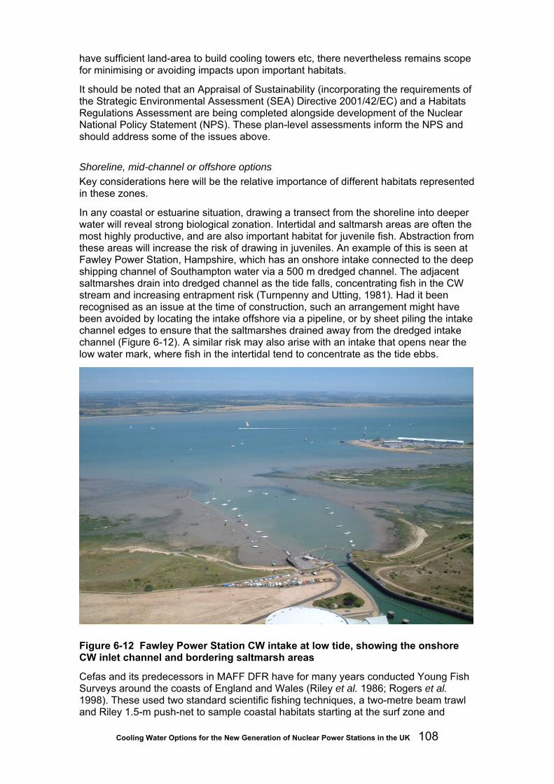
Cooling Water Options for the New Generation of Nuclear Power Stations in the UK 108
have sufficient land-area to build cooling towers etc, there nevertheless remains scope for minimising or avoiding impacts upon important habitats.
It should be noted that an Appraisal of Sustainability (incorporating the requirements of the Strategic Environmental Assessment (SEA) Directive 2001/42/EC) and a Habitats Regulations Assessment are being completed alongside development of the Nuclear National Policy Statement (NPS). These plan-level assessments inform the NPS and should address some of the issues above.
Shoreline, mid-channel or offshore options Key considerations here will be the relative importance of different habitats represented in these zones.
In any coastal or estuarine situation, drawing a transect from the shoreline into deeper water will reveal strong biological zonation. Intertidal and saltmarsh areas are often the most highly productive, and are also important habitat for juvenile fish. Abstraction from these areas will increase the risk of drawing in juveniles. An example of this is seen at Fawley Power Station, Hampshire, which has an onshore intake connected to the deep shipping channel of Southampton water via a 500 m dredged channel. The adjacent saltmarshes drain into dredged channel as the tide falls, concentrating fish in the CW stream and increasing entrapment risk (Turnpenny and Utting, 1981). Had it been recognised as an issue at the time of construction, such an arrangement might have been avoided by locating the intake offshore via a pipeline, or by sheet piling the intake channel edges to ensure that the saltmarshes drained away from the dredged intake channel (Figure 6-12). A similar risk may also arise with an intake that opens near the low water mark, where fish in the intertidal tend to concentrate as the tide ebbs.
Figure 6-12 Fawley Power Station CW intake at low tide, showing the onshore CW inlet channel and bordering saltmarsh areas
Cefas and its predecessors in MAFF DFR have for many years conducted Young Fish Surveys around the coasts of England and Wales (Riley et al. 1986; Rogers et al. 1998). These used two standard scientific fishing techniques, a two-metre beam trawl and Riley 1.5-m push-net to sample coastal habitats starting at the surf zone and
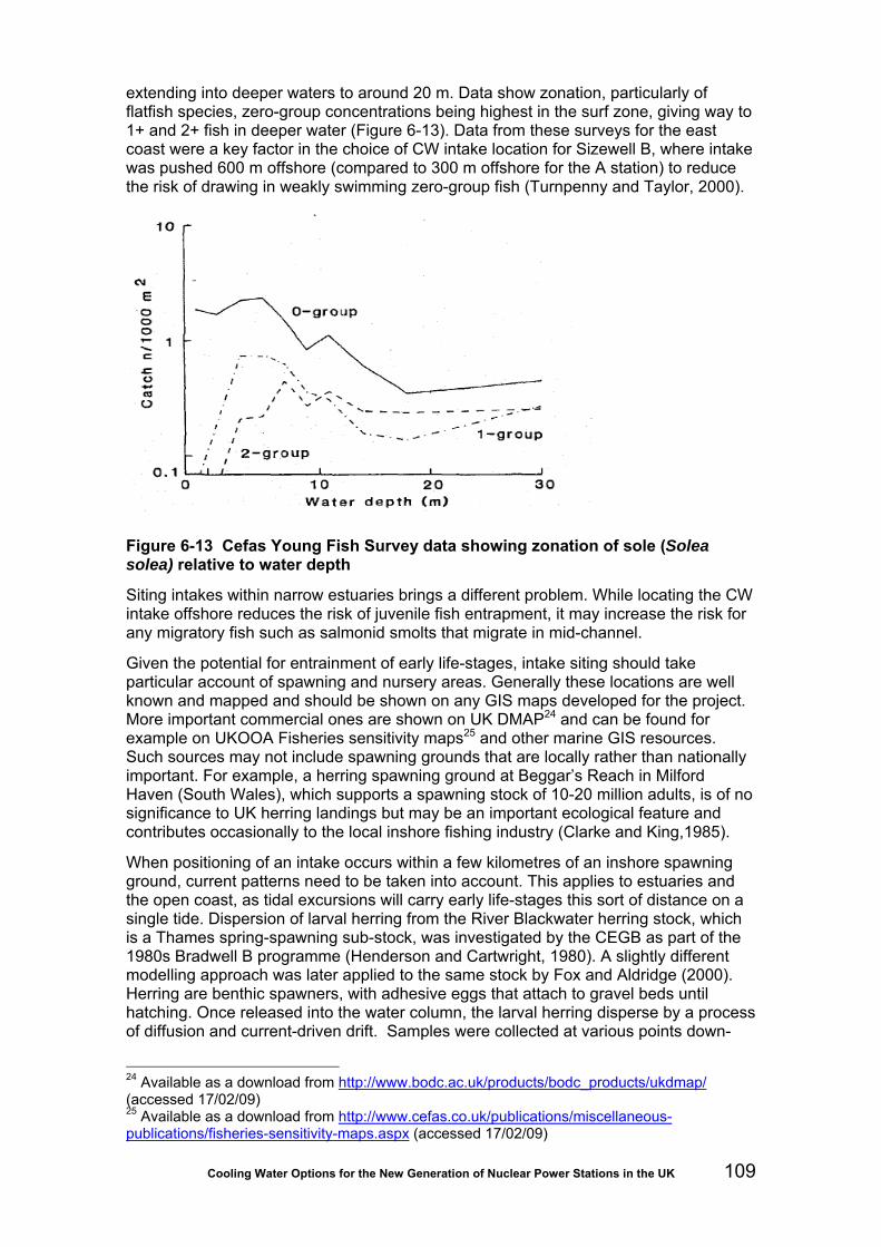
Cooling Water Options for the New Generation of Nuclear Power Stations in the UK 109
extending into deeper waters to around 20 m. Data show zonation, particularly of flatfish species, zero-group concentrations being highest in the surf zone, giving way to 1+ and 2+ fish in deeper water (Figure 6-13). Data from these surveys for the east coast were a key factor in the choice of CW intake location for Sizewell B, where intake was pushed 600 m offshore (compared to 300 m offshore for the A station) to reduce the risk of drawing in weakly swimming zero-group fish (Turnpenny and Taylor, 2000).
Figure 6-13 Cefas Young Fish Survey data showing zonation of sole (Solea solea) relative to water depth
Siting intakes within narrow estuaries brings a different problem. While locating the CW intake offshore reduces the risk of juvenile fish entrapment, it may increase the risk for any migratory fish such as salmonid smolts that migrate in mid-channel.
Given the potential for entrainment of early life-stages, intake siting should take particular account of spawning and nursery areas. Generally these locations are well known and mapped and should be shown on any GIS maps developed for the project. More important commercial ones are shown on UK DMAP24 and can be found for example on UKOOA Fisheries sensitivity maps25 and other marine GIS resources. Such sources may not include spawning grounds that are locally rather than nationally important. For example, a herring spawning ground at Beggar’s Reach in Milford Haven (South Wales), which supports a spawning stock of 10-20 million adults, is of no significance to UK herring landings but may be an important ecological feature and contributes occasionally to the local inshore fishing industry (Clarke and King,1985).
When positioning of an intake occurs within a few kilometres of an inshore spawning ground, current patterns need to be taken into account. This applies to estuaries and the open coast, as tidal excursions will carry early life-stages this sort of distance on a single tide. Dispersion of larval herring from the River Blackwater herring stock, which is a Thames spring-spawning sub-stock, was investigated by the CEGB as part of the 1980s Bradwell B programme (Henderson and Cartwright, 1980). A slightly different modelling approach was later applied to the same stock by Fox and Aldridge (2000). Herring are benthic spawners, with adhesive eggs that attach to gravel beds until hatching. Once released into the water column, the larval herring disperse by a process of diffusion and current-driven drift. Samples were collected at various points down-
24 Available as a download from http://www.bodc.ac.uk/products/bodc_products/ukdmap/ (accessed 17/02/09) 25 Available as a download from http://www.cefas.co.uk/publications/miscellaneous-publications/fisheries-sensitivity-maps.aspx (accessed 17/02/09)

Cooling Water Options for the New Generation of Nuclear Power Stations in the UK 110
tide towards the proposed intake location, which was 12 km from the Eagle Bank spawning ground. Both studies reached similar estimates of between 18 and 25 per cent of larvae being washed past the section of channel in which the intake was to be located over the 70 days following hatching (though only a proportion of these would be entrained). This type of approach is more useful for benthic spawning species as the spawning areas are more discrete than those of pelagic spawners such as sole, plaice or bass. Other benthic spawners include, for example, shads (Alosa spp.) and sand smelt (Atherina boyerii).
Recent investigations have been undertaken as part of the environmental assessment process for the planned Pembroke CCGT power station, whose CW intake will be located about 10 km from the Beggar’s Reach herring spawning ground mentioned above. Ichthyoplankton surveys close to the intake indicate that numbers of larval and post-larval herring in the CW volume required to supply the station during the post-hatching period would amount to no more than around 0.1 per cent of Milford Haven stock when expressed as adult equivalents.
The biological consequences of choice of intake opening depth have seldom been considered in past intake designs. As discussed in Section 5, the engineering preference is for deeper openings to avoid warmer surface layers and vortex formation. Fortuitously this is probably the better position for avoiding fish entrapment, as the bulk of fish drawn in are commonly pelagic species that favour the mid-to-upper water column. Bottom openings, conversely, will favour demersal and benthic species and the best arrangement may in most cases be to have openings a meter or so off the bed. This aspect needs to be considered on a site-specific basis according to conservation priorities.
Intake siting should also take account of the risk of operationally harmful inundations of biota. Little can be done to avoid exposure to mass inundations of jellyfish or sprat shoals in areas where these reach nuisance levels, as they are ubiquitous on these occasions. The emphasis in these cases should be on designing screening or deflection systems that can cope. Seaweed inundations, on the other hand, usually occur following storms, particularly after autumn dieback. Hydrographic factors then cause the material to accumulate in backwater areas or depressions in the seabed. Avoiding these areas when locating the intake can prevent later problems.
Biota exclusion and deflection techniques
Exclusion of fish, shrimps, weed and other organisms at the point of entry from the source water is greatly preferable to screening and returning them once they have entered the cooling system. Positive exclusion by fine mechanical screens is one approach but as discussed in Section 5.5 is unlikely to be considered for new nuclear sites. Other techniques depend on physical processes such as air bubble curtains to divert biota or upon behavioural stimuli to drive fish away from inlets.
Air bubble curtains Bubble curtains are formed when a porous or perforated pipe is affixed to the seabed and fed with compressed air. The rising curtain of bubbles so formed has a variety of useful properties in CW intake applications, including the ability to deflect organisms and trash and to reduce the risk of surface oil entering and coating the heat exchangers following a spill.
The mechanism by which this occurs is illustrated in Figure 6-14. In the case of organisms in the water column, as they are drawn towards the bubble curtain, they can become entrained into the vertical convection current generated by the rising bubble
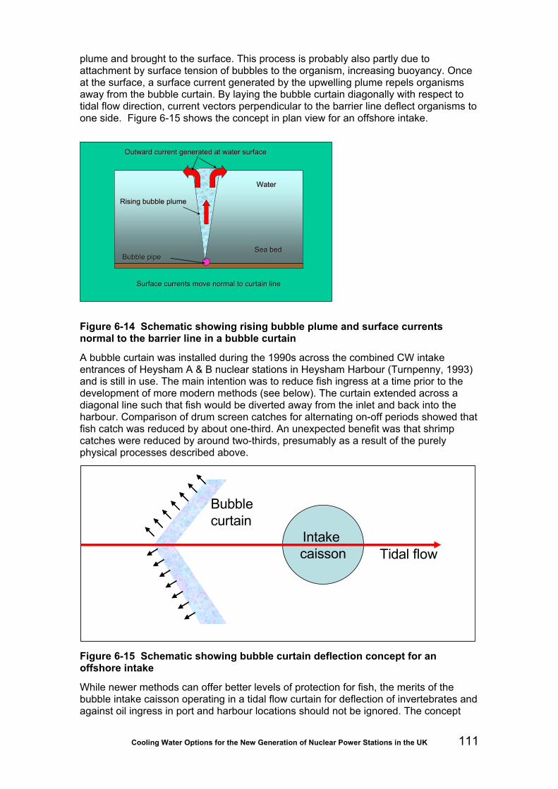
Cooling Water Options for the New Generation of Nuclear Power Stations in the UK 111
plume and brought to the surface. This process is probably also partly due to attachment by surface tension of bubbles to the organism, increasing buoyancy. Once at the surface, a surface current generated by the upwelling plume repels organisms away from the bubble curtain. By laying the bubble curtain diagonally with respect to tidal flow direction, current vectors perpendicular to the barrier line deflect organisms to one side. Figure 6-15 shows the concept in plan view for an offshore intake.
Sea bedSea bed
WaterWater
Rising bubble plumeRising bubble plume
Bubble pipeBubble pipe
Surface currents move normal to curtain lineSurface currents move normal to curtain line
Outward current generated at water surfaceOutward current generated at water surface
Sea bedSea bed
WaterWater
Rising bubble plumeRising bubble plume
Bubble pipeBubble pipe
Surface currents move normal to curtain lineSurface currents move normal to curtain line
Outward current generated at water surfaceOutward current generated at water surface
Figure 6-14 Schematic showing rising bubble plume and surface currents normal to the barrier line in a bubble curtain
A bubble curtain was installed during the 1990s across the combined CW intake entrances of Heysham A & B nuclear stations in Heysham Harbour (Turnpenny, 1993) and is still in use. The main intention was to reduce fish ingress at a time prior to the development of more modern methods (see below). The curtain extended across a diagonal line such that fish would be diverted away from the inlet and back into the harbour. Comparison of drum screen catches for alternating on-off periods showed that fish catch was reduced by about one-third. An unexpected benefit was that shrimp catches were reduced by around two-thirds, presumably as a result of the purely physical processes described above.
Tidal flowIntake caisson
Bubble curtain
Tidal flowIntake caisson
Bubble curtain
Figure 6-15 Schematic showing bubble curtain deflection concept for an offshore intake
While newer methods can offer better levels of protection for fish, the merits of the bubble intake caisson operating in a tidal flow curtain for deflection of invertebrates and against oil ingress in port and harbour locations should not be ignored. The concept

Cooling Water Options for the New Generation of Nuclear Power Stations in the UK 112
drawing in Figure 6-15 is based on a proposed scheme by Fawley Aquatic Research (now Jacobs Engineering) to reduce jellyfish ingress at Hunterston B nuclear station. The idea is to raise jellyfish in the water column by air becoming trapped beneath the umbrella, taking them over the top of the submerged intake structure, the chevron shape of the curtain at the same time pushing them outwards, away from the intake. It has not been implemented to date.
Bubble curtains have also been used to reduce siltation risk at some power stations, where accretion can partially block openings and cause intake velocities to exceed licensed conditions. An experimental curtain was used to dislodge silt depots around Barking power station on the Thames Tideway but was found to be difficult to maintain. Another is used across the CW intake channel of Fawley power station to reduce sedimentation across the inlet at times when the plant is not drawing CW flow.
Velocity control Active or behavioural deflection of fish first requires velocities at the intake entrance (often known as “approach velocities”) to be low enough for fish to avoid. Design criteria for fish conserving intakes therefore rely on good knowledge of the swimming performance of different fish species and life-stages. As fish are poikilotherms (body temperature is determined by external water temperature), water temperature has a strong influence on metabolic rates and therefore swimming performance.
At one time, relatively crude swimming-speed criteria based on non-indigenous fish species were used for this purpose. More recently the power and water industries, as well as the Environment Agency, have seen the need to develop a database for UK inland and saltwater species. Relevant information is summarised in the Best Practice Guide (Turnpenny and O’Keeffe, 2005). For most power plant intake purposes a design fish-escape velocity of 0.3 ms-1 will be suitable and meet best practice requirements. Where a different value might be preferable, the guide should be consulted.
Two further design issues relating to velocity are relevant to offshore intake structures. One concerns elimination of vertical velocity components, which fish are ill-equipped to resist. The problem can be overcome by fitting a “velocity cap” over the intake to ensure that water enters horizontally. Care should be taken to ensure that the aspect ratio (height:length) of the entrance meets the criteria presented by Schuler and Larson (1975) (Figure 6-16), which ensure that vertical components are eliminated. Velocity caps are a powerful form of mitigation that can reduce entrapment by up to 90 per cent, and are already used in some newer UK offshore intake designs (such as Sizewell B: Turnpenny and Taylor, 2000).

Cooling Water Options for the New Generation of Nuclear Power Stations in the UK 113
Figure 6-16 Velocity cap: (a) section of uncapped intake showing vertical draw-down pattern, (b) section of capped intake showing horizontal flow pattern, (c) as (b) but showing critical relationship between vertical opening [x] and length of horizontal entrance [1.5x] for fish reactions (after Schuler and Larson, 1975)
The second issue concerns the orientation of intake openings in relation to tidal or river flow. Many UK stations with offshore intakes can take water from 360o around the circumference of the structure. Hydraulic modelling studies have shown that resulting velocities on the upstream side of the intake approximate the sum of the intake velocity (calculated as if there were no crossflow) and the approaching tidal stream velocity (Turnpenny, 1988a). Whereas Sizewell B was designed with a nominal entrance velocity of 0.5 ms-1 under static water conditions, the actual approach velocity can be several times this value in mid-flood and mid-ebb periods, leading to higher fish impingement rates at these times. The Best Practice Guide (Turnpenny and O’Keeffe, 2005) presents a conceptual design (Figure 6-17), the low velocity side-entry (LVSE) intake that appears from initial modelling tests to overcome the problem and maintain constant velocities around the tidal cycle. As yet, this design has not been built and requires further model testing to develop the detailed design and ensure its suitability.

Cooling Water Options for the New Generation of Nuclear Power Stations in the UK 114
Figure 6-17 Concept design for a low-velocity, side-entry offshore intake structure with velocity cap, based on physical and hydraulic model tests carried out at Fawley Aquatic Research Laboratories (Turnpenny, 1988a and unpublished). A and B are the cylindrical caissons. Water enters through C.
Acoustic fish deterrents and strobe lights A recent innovation to reduce fish entry into CW intakes is the acoustic fish deterrent (AFD) system. AFDs were originally investigated by the CEGB for Severn Barrage tidal power generation, where the need to exclude fish from hydropower turbines passing up to 200 m3s-1 was considered to preclude conventional physical screening methods. When the Severn Barrage project of the 1990s was dropped, the nuclear industry saw the benefits of pursuing AFD development and early trials were carried out at Hinkley Point (Turnpenny, Thatcher and Wood, 1994) and Hartlepool (Turnpenny et al. 1995 ) nuclear stations. Hinkley Point trials showed that fish impingement rates could be affected by the AFD’s sound field, but catches increased rather than decreased! The AFD system used at Hinkley was made up of off-the-shelf military hardware and was not ideally suited to generating frequencies audible to fish. The reason for increased fish catch appeared to be the sound field causing fish to concentrate at the depths from which water was abstracted. For the second series of trials, conducted at Hartlepool, more suitable acoustic transducers (“sound projectors”) were developed. These, along with better use of acoustic modelling software to optimise the sound field, led to the successful deflection of a large proportion of fish. Following privatisation of the CEGB and the nuclear industry, independent private sector development continued the refinement of AFDs, there now being a variety of AFD systems suited to different uses.
AFD systems have become commonplace at large abstractions where physical fish screening (as opposed to trash screening) is problematic. They have been installed at large thermal stations such as Doel nuclear station (Belgium), Fawley (oil-fired, Southampton Water), Shoreham (CCGT, West Sussex), Great Yarmouth (CCGT, Norfolk), Marchwood (CCGT, Southampton Water) and Staythorpe (CCGT, R. Trent) and systems are scheduled for installation at other new stations. A system was recently

Cooling Water Options for the New Generation of Nuclear Power Stations in the UK 115
installed at Lambton Generating Station, a large direct-cooled plant on St Clair River in Canada.
The fish deflection performance has been investigated at a number of installations. Testing usually involves comparing screen catches for a sequence of AFD “off” versus “on” days. The cases most representative of the latest technology combined with use of acoustic modelling techniques are Doel (table 6-6) and Lambton. The effectiveness of the system depends mainly on the hearing sensitivity of individual species, although other factors such a swimming ability must be taken into account. Most fish possess a swimbladder, which increases sensitivity to sound pressure. Such species (which include many demersal species, including most members of the cod family, bass and other ‘roundfish’) can be deflected with sound. AFD deflection efficiencies are usually between 50-70 per cent for these species. A smaller group of species, known as ‘hearing specialists’, have anatomical adaptations that increase sensitivity to sound. Examples include pelagic fish such as herring and sprat, but also members of the carp family and catfishes. Deflection efficiencies are correspondingly higher, around 80-95 per cent, for these species. A third group comprises flatfishes and other benthic species with reduced or no swimbladder function. Efficiencies are considerably lower for these species. In theory, installing more sound projectors and increasing sound levels will increase the efficiency for all species but the law of diminishing returns applies, and it is normally more cost-effective to add a second type of stimulus, such as strobe lights, and/or to combine AFDs with a fish recovery and return system.
AFD systems that have been used most successfully at power stations deliver sound signals in the 10 to 3,000 Hz hearing band that is audible to most fish26. Systems comprise a single signal generator, designed to provide a suite of signals selected according to species, a bank of audio power amplifiers, and a sound projector connected to each amplifier (Figure 6-18). Each line can also be provided with a diagnostics unit, which allows the performance status of all elements of the system to be monitored remotely, for example in the plant control room or via a website.
Sound projectors (Figure 6-19) are installed in a matrix or array across intake entrances, creating a localised, repellent sound field. Normally these are attached to vertical rails incorporating a winch mechanism that enables them to be drawn to the surface for maintenance (at least annually). Figure 6-19 shows the substantial sound projector support structure used at the Canadian Lambton station, designed to ensure that the sound field extends to a point where velocities are low enough for fish to escape. An important consideration for nuclear stations under construction, especially those with offshore CW intakes, is to ensure that suitable cable ducts and cable runs are provided between the onshore station buildings and the intake structure. As cables are difficult to replace, it is also good practice to provide additional spare cabling to allow for future expansion of the AFD system, if necessary, or to replace failed cables.
26 Ultrasound (>100 kHz) systems have been used with some success in the USA for certain species with ultrasound sensitivity (clupeid family) (Turnpenny and O’Keeffe, 2005) but are not effective for other species and would not therefore be suitable for new UK nuclear build.

Cooling Water Options for the New Generation of Nuclear Power Stations in the UK 116
Table 6-6 Deflection efficiencies reported for the acoustic fish deflection system at Doel nuclear station (Maes et al. 2004)
Fish species Deflection efficiency (‘on’
versus ‘off’)
Statistical significance
Herring (Clupea harengus) 95% P<0.001 Sprat (Spratus sprattus) 88% P<0.001
Smelt (Osmerus eperlanus) 64% P=0.004 Bass (Dicentrarchus labrax) 76% P<0.001 Flounder (Platichthys flesus) 46% P=.0.028
Gobies (Pomatoschistus spp.) 50% P>0.05 (NS)
Sound Projector
Diagnostic Unit
Amplifier
Sound Projector
Diagnostic Unit
Amplifier
Sound Projector
Diagnostic Unit
Amplifier
Sound Projector
Diagnostic Unit
Amplifier
Sound Projector
Diagnostic Unit
Amplifier
Sound Projector
Diagnostic Unit
Amplifier
Signal Generator
Figure 6-18 Schematic layout of a sound projector array (SPA) acoustic fish deterrent system with six sound projectors. Large systems may use up to 60 sound projectors, each with a dedicated amplifier and diagnostics unit.

Cooling Water Options for the New Generation of Nuclear Power Stations in the UK 117
Figure 6-19 Example of an acoustic fish deterrent support structure constructed across a shoreline CW intake at the Lambton Generating Station, St Clairs River, Canada. The vertical beams each act as rails, which allow sound projectors to be raised and lowered for maintenance. The positioning of the structure ahead of the intake opening ensures that the fish repulsion zone is in an area of low water velocities from which the fish can escape. The inset shows an individual sound projector. (Main photo courtesy Paul Patrick, Kinectrics).
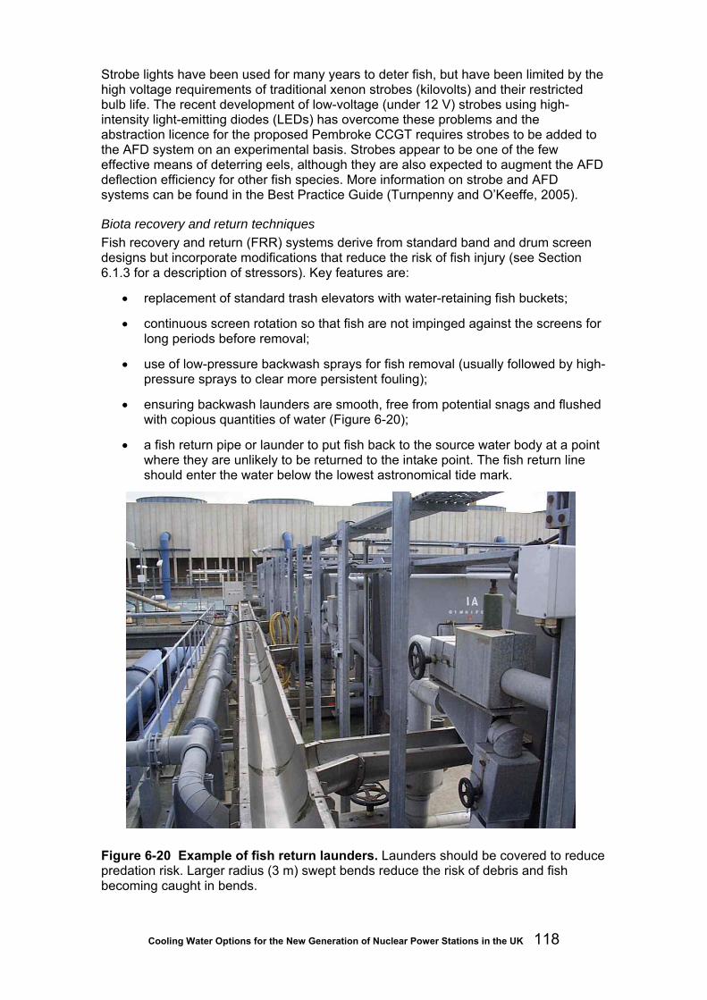
Cooling Water Options for the New Generation of Nuclear Power Stations in the UK 118
Strobe lights have been used for many years to deter fish, but have been limited by the high voltage requirements of traditional xenon strobes (kilovolts) and their restricted bulb life. The recent development of low-voltage (under 12 V) strobes using high-intensity light-emitting diodes (LEDs) has overcome these problems and the abstraction licence for the proposed Pembroke CCGT requires strobes to be added to the AFD system on an experimental basis. Strobes appear to be one of the few effective means of deterring eels, although they are also expected to augment the AFD deflection efficiency for other fish species. More information on strobe and AFD systems can be found in the Best Practice Guide (Turnpenny and O’Keeffe, 2005).
Biota recovery and return techniques Fish recovery and return (FRR) systems derive from standard band and drum screen designs but incorporate modifications that reduce the risk of fish injury (see Section 6.1.3 for a description of stressors). Key features are:
• replacement of standard trash elevators with water-retaining fish buckets;
• continuous screen rotation so that fish are not impinged against the screens for long periods before removal;
• use of low-pressure backwash sprays for fish removal (usually followed by high-pressure sprays to clear more persistent fouling);
• ensuring backwash launders are smooth, free from potential snags and flushed with copious quantities of water (Figure 6-20);
• a fish return pipe or launder to put fish back to the source water body at a point where they are unlikely to be returned to the intake point. The fish return line should enter the water below the lowest astronomical tide mark.
Figure 6-20 Example of fish return launders. Launders should be covered to reduce predation risk. Larger radius (3 m) swept bends reduce the risk of debris and fish becoming caught in bends.
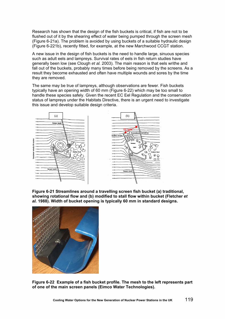
Cooling Water Options for the New Generation of Nuclear Power Stations in the UK 119
Research has shown that the design of the fish buckets is critical, if fish are not to be flushed out of it by the shearing effect of water being pumped through the screen mesh (Figure 6-21a). The problem is avoided by using buckets of a suitable hydraulic design (Figure 6-221b), recently fitted, for example, at the new Marchwood CCGT station.
A new issue in the design of fish buckets is the need to handle large, sinuous species such as adult eels and lampreys. Survival rates of eels in fish return studies have generally been low (see Clough et al. 2003). The main reason is that eels writhe and fall out of the buckets, probably many times before being removed by the screens. As a result they become exhausted and often have multiple wounds and sores by the time they are removed.
The same may be true of lampreys, although observations are fewer. Fish buckets typically have an opening width of 60 mm (Figure 6-22) which may be too small to handle these species safely. Given the recent EC Eel Regulation and the conservation status of lampreys under the Habitats Directive, there is an urgent need to investigate this issue and develop suitable design criteria.
Figure 6-21 Streamlines around a travelling screen fish bucket (a) traditional, showing rotational flow and (b) modified to stall flow within bucket (Fletcher et al. 1988). Width of bucket opening is typically 60 mm in standard designs.
Figure 6-22 Example of a fish bucket profile. The mesh to the left represents part of one of the main screen panels (Eimco Water Technologies).
(a)
(b)
60 mm
(b)

Cooling Water Options for the New Generation of Nuclear Power Stations in the UK 120
Biocides used for biofouling control within the CW system should ideally be injected downstream of the screenwell to avoid toxic stress to the fish being returned. While Turnpenny (1992) concluded that brief exposure to TRO may be tolerated by fish, exposure to sublethal effects of TRO may disorientate fish and increase the risk of predation once they are released back to the wild. The Best Practice Guide (Turnpenny and O’Keeffe, 2005) therefore recommends that exposure be avoided, although screenwells are often chlorinated. This recommendation has yet to meet with a satisfactory response from developers, who are concerned about biofouling accreting within the screenwells and potentially blocking screens, a problem which may need to be addressed with intermittent shock dosing or use of antifouling coatings.
The Best Practice Guide gives the following summary of design criteria for FRR systems, which should be applied as far as possible at new nuclear stations:
• The design of the fish buckets should be optimized for fish handling.
• Screen meshes should be smooth and fish-friendly, constructed from woven stainless steel or plastic mesh.
• Mesh size should be 6 mm or less.
• Low-pressure backwash sprays (under one bar) should be used for fish removal; higher pressure jets may be used at a later point in the cycle to wash off debris.
• The geometry of the collecting hoppers should ensure that fish washed off the screens cannot fall back into the screenwell.
• Biocides should be applied only downstream of the screens unless it can be shown that the toxic risk is negligible.
• Fish return gullies should be smooth, with any joints properly grouted and finished. They should have a minimum of 0.3 m diameter with at least 0.5 m diameter or larger for the main return channel run (above 30 m).
• Fish return lines should be covered to prevent bird predation and algal growth, with access for cleaning.
• Swept bends of radius greater than three metres should be used.
• A dedicated fish return line should be provided.
• A continuous wash-water supply should be provided to ensure sufficient depth to keep fish immersed and moving along the return line.
Putting these guidelines into practice at recent new-build stations has already revealed further details that should be specified, and other requirements may come to light as experience is gained. The following additional design criteria should be considered:
• In order to minimise the fish handling time the screens should be rotated at a constant speed of at least 1.5 m per minute.
• Any changes in slope of launders should use a minimum 3-m swept bend radius for vertical bends to avoid flow separation from the launder bed.
• The fall on launder sections feeding into horizontal bends should be restricted, as accelerating flow may cause standing waves and overtopping in the bends. This may be accomplished, for example, by restricting the fall on launder sections upstream of horizontal bend to 1 maximum of 1:50.

Cooling Water Options for the New Generation of Nuclear Power Stations in the UK 121
• Turbulence should be minimised to reduce the risks of fish exhaustion and injury. It is recommended that energy dissipation throughout the system should be kept at or below 100 Wm-3. This particularly applies to any fish sampling or holding facility that may be incorporated for fish impingement monitoring purposes. The method of calculating energy dissipation is described in the Environment Agency Fish Pass Manual (Armstrong et al., 2004).
• While most FRR systems allow the high-pressure backwash (primarily intended to remove material sticking to the screen) to discharge to a trash basket, provision should also be made to allow discharge of backwashings via the fish return launders. This facility can be used in cases where significant quantities of shrimps, for example, would otherwise be sent to landfill rather than returned to sea. At times when it is mostly weed and rubbish that are removed at the high-pressure wash stage, the material could be collected for disposal.
The geometry of band screens makes them more adaptable than drum screens to fish handling and most FRR development has been based on the band screen format. As it is likely that drum screens will be used in new nuclear stations, the difficulties of drum screen geometry will require attention. The main issue is that the tipping radius of the fish bucket is much larger than on band screens, so fish tend to fall out of the bucket towards the collection hopper over a relatively large arc. Thus, a large proportion of fish can fall back into the screenwell and may have to be handled multiple times before successful removal. Figure 6-23 illustrates this problem with a photograph from one nuclear plant where scaffold boards had been placed in front of the hopper and were seen to collect quantities of fish that missed the hopper.
Figure 6-23 Fish that have overshot the hopper collecting on a scaffold boards inside a drum screen chamber
Where the use of biocides upstream of fish return facilities is critical to security of plant operation, a suitable ecotoxicological risk assessment should be carried out to ensure that any risk of adverse lethal and sublethal effects on fish is minimised, and that the

Cooling Water Options for the New Generation of Nuclear Power Stations in the UK 122
level of ecological impact associated with biocide use is acceptable. Wherever practicable, biocide application should be conducted on inactive legs of the CW system (for example, soak application when no abstraction is taking place) or at times of the year when fish entry is likely to be minimal.
Neither the AFD nor FRR systems used in Britain are capable of protecting small fish of less than around 30 mm in length, which are vulnerable to entrainment.
6.1.7 Special measures at Natura 2000 sites?
No separate regulations or standards on impingement and entrainment apply to Natura 2000 sites but particular attention needs to be paid to species listed in the conservation objectives for the site. Fish species listed under Annex 2 of the Habitats Directive (92/43/EEC) include:
• River lamprey (Lampetra fluviatilis)
• Sea lamprey (Petromyzon marinus)
• Brook lamprey (Lampetra planeri)
• Atlantic salmon (Salmo salar)
• Bullhead (Cottus gobio)
• Spined loach (Cobitis taenia)
• Allis shad (Alosa alosa)
• Twaite shad (Alosa fallax).
Of these, the three lamprey species as well as loach and bullhead are benthic and likely to be insensitive to AFD techniques but amenable to FRR methods. Conversely, salmon and shad are too delicate for FRR but can be deflected by behavioural methods.
Compliance with the Habitats Directive does not necessarily mean that the project must lie within the designated area of the SAC; if the project might indirectly have an impact on the SAC, such as an abstraction on the migration path of a designated species attempting to reach the SAC, then it will also be subject to the Habitat Regulations27.
Any development that might affect a Natura 2000 site will be subject to a regulatory assessment process by the competent authority (The Environment Agency of England and Wales). In such an assessment there will be an initial screening stage, which seeks to determine whether the proposed development is likely to have a significant impact on conservation features of the European-protected site. Where there is considered to be a significant risk, then the competent authority will undertake an appropriate assessment to evaluate that risk. Where a significant impact is predicted, approval to proceed with the development will be granted only if the proposed project can be modified to mitigate the significant impacts, or is subject to ‘overriding public interest’ considerations. Further details can be found in various guidance documents (see e.g. http://www.mceu.gov.uk/MCEU_LOCAL/Ref-Docs/EN-HabsRegs-AA.pdf [accessed 08/01/10).
27 Conservation (Natural Habitats & Conservation) Regulations 1994

Cooling Water Options for the New Generation of Nuclear Power Stations in the UK 123
6.1.8 Residual impacts
The environmental impact assessment for a new nuclear station should attempt to quantify, among other things:
(a) the proportion of fish present in the approaching CW flow that would be deflected by mitigation measures at the intake structure;
(b) the proportion of impinged fish that would be returned safely to the source water body by FRR measures;
(c) the proportion of entrained early life-stages that would pass back unharmed to the source water body.
Residual impacts will then arise from impinged and entrained fish that are returned to the wild, dead or injured. The residual impact is reduced further by the reassimilation of this biomass back into the food chain, although this is more difficult to quantify.
Residual impacts from a development may be offset by appropriate forms of compensation. These should be in kind, and at least commensurate with the level of residual impact. The California Energy Commission approach provides a model for this (CEC, 2005), in which the residual biomass loss is converted to habitat production foregone (HPF) (Section 6.1.5) and then new habitat to the equivalent or greater area is created. UK examples of best practice for lost estuarine and coastal production are emerging from parallel considerations in various industrial sectors where coastal habitat projects have been funded (Table 6-7).
Table 6-7 Example of large-scale habitat compensation projects in the UK (Scottish Parliament, 2008)
An important consideration in determining compensation is that it should match as closely as possible the loss of species and life-stages. It is normal practice to provide in compensation a larger habitat area, around 1.5 times the estimated HPF figure, to allow for error in the estimate, any underperformance of the replacement habitat and habitat maturation time.

Cooling Water Options for the New Generation of Nuclear Power Stations in the UK 124
6.2 Effects of cooling towers
6.2.1 Aerial emissions
Pathogens
The primary concern is with Legionella pneumophila that was first recognised in 1977 as the causative agent of a form of infective pneumonia. There are at least 14 serotypes and several subtypes that differ in their distribution and pathogenicity. Various estimates suggest that Legionnaires’ disease, LD, constitutes about 0.1 to 0.2 per cent of all pneumonias in the UK, but, as pre-1977, it is probable that an unknown number of infections will go unrecognised. The organisms are ubiquitous in natural waters and may have a symbiotic relationship with protozoa in biofilms. For a water system to give rise to risk, the following factors are needed:
• a source of the organisms – invariably present in river make-up water; • favourable conditions for growth:
temperature 20-45˚C; existing microbiofouling – typically a mature bacterial slime; iron or its salts; stagnation;
• a means of generating a respirable aerosol; • sufficient concentration of infective organisms to provide an effective dose; • an opportunity to inhale a contaminated aerosol; • a susceptible individual, typically male and unhealthy, aged 40-70.
To date no link has been established between an infection and power station cooling towers. However there are several cases where a small wet-cooler on an air-conditioning unit has caused an outbreak and so it could be argued that a group of large power station towers could produce an epidemic. Surveys have shown that Legionella, at low concentrations, have frequently been present in make-up water and in most areas of the cooling circuit at concentrations of up to106 cfu/l28. A wide range of concentrations can be found in different parts of the circuit on the same day and there is also day-to-day variation. Initial surveys using samplers suspended from meteorological balloons inside natural draught towers at West Burton (UK) indicated a decrease in viable heterotrophic bacteria, VHBs, with height; no Legionella were detected above the eliminators. However, other bacteria from the cooling circuit were found in droplets above the eliminators and in similar concentrations to those in the cooling water. The next question was whether viable bacteria were leaving the tower. This proved difficult to assess but simulations did not suggest that physical stress reduced VHBs so it is unreasonable to assume that Legionella would not survive. The ability of Legionella to survive in air after leaving the tower is of paramount importance to the assessment of risk. Legionella viability in an aerosol improves with increased humidity. In low humidity air osmotic and physical stress, as produced within a contracting droplet, tend to decrease Legionella’s metabolic activity but, perversely, improves its resistance to further perturbation. The presence of dissolved salts and organic material will tend to decrease the rate of droplet evaporation. The so-called “open air factor” and the effects of UV radiation are critical to the survival of many micro-organisms, but Legionella have been found within encysted amoebae where they
28 cfu – colony forming units (per litre of water). The CEGB studies used plate-counts, following DoH potable water practice and HSC guidelines.

Cooling Water Options for the New Generation of Nuclear Power Stations in the UK 125
are protected from most stress and this would permit dispersal over long distances. In the 1988 BBC (London) outbreak, infection was acquired 500 m from the source and in Wisconsin infections were reported from two miles away. The BBC outbreak coincided with mild, dull and humid conditions providing optimal humidity, protection from the sun and limiting dispersal of the aerosol by turbulence. To date there have been no cases of legionellosis amongst power station workers related to exposure to drift or to blowout.
Salt dispersal
There are three sources of small droplets in natural draught towers – the water distribution spray-nozzles themselves, secondary droplets formed as the spray hits the top of the pack (film pack) or splashes down through the slats (splash pack) and condensation. The water distribution system is low-pressure and generally produces droplets greater than 200 μm diameter, too large to make any direct contribution to carryover. However with piped rather than open channel, distribution system blocked nozzles will raise the pressure at unblocked nozzles and generate more small droplets. Droplets in the range 50-200 μm diameter are small enough to ascend the tower, but eliminators fitted above the tower’s water distribution system and pack should intercept 95 per cent of droplets under 100 μm. Eliminators are similar in design to steam driers and prevent the passage of water droplets by forcing the airflow to make multiple directional changes. However there is a trade-off between removal efficiency and resistance to airflow. A well-designed, well-fitted and maintained eliminator can greatly reduce water loss, solids and biological carryover. Condensation arising from evaporative heat exchange generates droplets under 50 μm diameter (mean over 20 μm) that constitute the visible plume. Theoretical studies, supported by observations inside towers, have revealed the conditions necessary for droplet growth. At all stages droplet size is the most important parameter. The smallest droplets (under 50 μm) remain in suspension but contribute little to the growth of other droplets. Droplets in the range 100-150 μm tend to coalescence with smaller droplets and provide the main source for droplet growth. Air velocities decrease significantly above the “throat” (vena contracta) of a hyperbolic tower so many larger droplets (above 250 μm) will hit the tower shell and drip back onto the eliminators as “downrain”. Droplets of 240-360 μm in the fastest airflow can be carried out of the top of the tower by a typical 1.0-1.4 ms-1 updraft. Direct measurements of carryover using Andersen cyclone samplers and isokinetic samplers inside and outside natural draught cooling towers were attempted at Drax, Yorkshire (for pathogens) and at Ince, Cheshire (for salt).
Growth by coalescence continues in the plume and most detectable precipitation beneath the plume is droplets in the range 200-350 μm. Average drop size decreases with distance from the tower and peak rain-out typically occurs within a few hundred to a thousand metres downwind. If relative humidity is less than saturation considerable evaporation will occur, further restricting rain-out. However the presence of large, and increasing, concentrations of dissolved salts in the droplets inhibits evaporation and can extend the rain-out area. Clouds that may be formed by the plume at some distance from the tower had a greater concentration of aerosol (0.2 μm) droplets (Mertes and Wendisch, 1997).
With induced draught mechanical towers, the air velocity is highest at the exit and these can be more prone to carryover than forced draught towers where air velocities are highest at the air entry. The wet-air path in both of these types of tower is far shorter than in natural draught towers so there is little opportunity for droplet coalescence. However, in view of the consistently high air velocity, it is essential that the eliminators remain intact and in place.
Cooling Water Options for the New Generation of Nuclear Power Stations in the UK 126
A comprehensive desk and field study of salt dispersal from proposed seawater cooling towers at Winfrith (Dorset) concluded that the projected rate of salt deposition would not be distinguishable from a background of naturally occurring deposition at this exposed, near-coast, site. In all coastal areas, onshore winds carry salt inland and, even when weather systems are not producing onshore winds, a “sea breeze” often develops during the day. The weight of salt carried and the direction and distance will vary from day to day, so any estimate of salt drift from towers has to be detectable against this wide spatial and temporal variability. As with coastal erosion, a single storm event can produce more salt damage to vegetation than decades of “normal” deposition. If salt drift is uniformly spread around a tower, the annual rate of deposition can be up to three orders-of-magnitude less than the rate of natural deposition 600 m inland from the ocean (Parker, 1979). Ince measurements that were part of the Winfrith study found that local deposition was greatest during rainfall.
The main problem usually identified with salt drift is build-up in the soil and scorching of vegetation, with economic effects on forestry and agriculture, although at Winfrith the requirement was to protect a sensitive heathland habitat. Although salt drift was raised as an issue at the planning stage for Deeside, Connah’s Quay and for both of the Killingholme CCGT’s there has been no evidence of adverse off-site effects attributable to salt drift and no subsequent mention of the topic in the fifteen or so years for which some of these plants have been operating. Earlier, Roffman and Roffman (1973) had used deposition models to calculate possible incremental increases in the salinity of soil, irrigation water and natural fresh waters from natural and mechanical draught salt water cooling towers. The incremental effects of salt deposition from 1,000 MWe towers (circulation rate of 31.5 m3s-1 and 0.002 per cent drift) upon the surrounding soil and water generally were minimal. Some extreme cases may develop under severe weather conditions, but these will be infrequent and will represent a small fraction of the total operating time. Studies around five seawater cooling towers near Galveston (Wiedenfeld, 1978) found levels as high as 1,200 kg ha-1 per year within 100 m, decreasing logarithmically with distance to under 300 kg ha-1 per year at 434 m. Only 16 per cent was attributable to the cooling towers; the balance was natural sea spray that averages about 250 kg ha-1 per year in the study area. There were only slight observable effects in the soils closest to the towers that may eventually lead to salinization and solonization (clay deflocculation due to high sodium levels).
Fog and ice
Plumes of water vapour (fog) can often be seen rising from cooling towers. This occurs when the warm saturated air leaving the tower mixes with ambient air and is cooled to its saturation value. The visibility of the plume depends upon the concentration of micro-droplets that have condensed from the vapour and upon the direction of illumination. Back-lit plumes are dark, and are frequently mistaken by the media as symbols of industrial pollution. Front-lit plumes are bright white. Plumes are bigger and more persistent when the ambient air is at or near saturation. The visible plume may rise until its buoyancy is in equilibrium with the ambient air and it becomes “cloud”; alternatively the visible plume may vanish a short distance above the tower but reappear as cloud at altitude some distance downwind.
In cold weather, droplets in the plume may become supercooled and coat adjacent surfaces in ice. Alternatively, the ground may be below freezing point and ice will form where it contacts the cooling, sinking plume. Icing is mainly a problem associated with low, mechanical draught towers. TRC (2007) indicates the limitations of a modelling approach. Modelling could predict whether the plume water vapour content was greater than or less than the ambient saturation deficit and therefore the potential presence of a condensed plume, but could not estimate plume density, that is, whether or not the plume was barely saturated and would be evaporating. Similarly it would predict ground

Cooling Water Options for the New Generation of Nuclear Power Stations in the UK 127
(rime) icing whenever it predicted a ground fog coinciding with sub-zero (centigrade) air temperatures. These conditions may be conducive to rime ice formation, not actual formation of rime ice, which is a complex process and strongly affected by factors such as density of supercooled liquid water in the plume, plume orientation and wind speed. The model also considered plume abatement (plume mitigation) by diverting 10 per cent of the incoming water through the dry section of a hybrid tower. Heat rejection through the dry section was assumed to be five per cent of total tower heat duty, reflecting the fact that about half of the heat rejection duty of the tower during cool weather is achieved by sensible heat transfer, rather than by evaporation. This abatement is anticipated to result in negligible plume fogging or icing beyond the site.
6.2.2 Visual and aesthetics
Public concern over cooling towers mainly stems from the visual impact of these large structures, especially the commoner hyperbolic natural draught towers, along with their visible vapour plumes. According to Winter (1997), planning authorities have been increasingly reluctant to accept visible plumes since the privatisation of the UK power industry and this would be a key consideration of nuclear plant developers in selecting a viable cooling system.
In order of visual impact, natural draught cooling towers are the most offensive, typically being 100 m tall or higher and invariably with a visible plume, followed by mechanical draught and hybrid mechanical draught and dry cooling towers (all around 40 m in height). Of the last three types, vapour plumes are greatest with the first and absent with dry cooling; hybrid towers reduce the visible plume by heating moist air on heat exchangers before it leaves the tower.
Guidance on assessing the visual impact of aerial plumes is given in Section 3.8 of the IPPC Horizontal Guidance Note (Environment Agency, 2003). Criteria for assessing a visual impact are:
• percentage of daylight time that the visible plume or its shadow extends beyond the site boundary of the plant;
• frequency of impact on surrounding area;
• presence of sensitive receptors.
An impact is only deemed to be insignificant if the visible plume extends beyond the boundary for less than five per cent of daylight hours, the impact is deemed to be small and there are no sensitive local receptors.
6.2.3 Chlorination by-products
The addition of chlorine to water is an instantaneous reaction resulting in an equilibrium
mixture of hypochlorous acid (HOCl) and hypochlorite ions (OCl- ):
Cl2 + H2O <> HCl + HOCl
HOCl <> H+ + OCl-
With sodium hypochlorite:
NaOCl <> Na+ + OCl-

Cooling Water Options for the New Generation of Nuclear Power Stations in the UK 128
H+ + OCL- <> HOCl
there is a 50:50 mixture of the “free chlorine” oxidants HOCl and OCl- at pH 7.5 but the
equilibrium shifts towards OCl- with rising pH. Tower circuits tend to stabilise around pH 8.5 which is unfortunate since HOCL is a more powerful oxidant, and hence
biocide, than OCl-. On the other hand HOCL is volatile whereas OCl- is not, so at this pH more of the free chlorine will remain in solution. Reactions begin immediately with any ammonia and organic amines that may be in the water, forming inorganic and organic chloramines (“combined chlorine”). Ferrous and manganous ions, sulphides, sulphites and nitrites are simply oxidised whereas organic material may undergo oxidation, addition or substitution reactions. Most of this organic material - such as humic and fulvic acids - is of natural origin and ubiquitous in natural waters. When chlorinated these yield a range of compounds (“chlorination byproducts” or CBPs), some of the most common being haloforms such as chloroform.
Holzwarth et al. (1984a & b) modelled the fate of chlorine in intermittently chlorinated wet-tower cooling circuits and identified three pathways for loss:
(a) flash-off or stripping as the air stream through the cooling tower strips HOCl and volatile chlorination products from the water;
(b) purge or blowdown that dumps a proportion of the free and combined chlorine and CBPs into the receiving waterway;
(c) chlorine demand that steadily converts the biocide to inert (non-oxidant) CBPs.
Although the authors made no allowance for any “chlorine” lost in drift (blow out) from the base of a tower, there was good agreement between observed and predicted free chlorine concentrations throughout the chlorination cycle in the tower used for model validation. About 10-15 per cent of the HOCl was stripped on each passage through the tower and overall about 10 per cent of the added chlorine flashed off, two per cent was purged and 88 per cent was “consumed” as demand. Adding acid to reduce the pH from 8.5 to 6.0 increased HOCl flash-off ten-fold, so any benefit to biocidal activity would have been cancelled by greater oxidant loss and by the cost of acid required. Mono-, di- and trichloramines flash-off much faster than HOCl, so their value as biocides in tower circuits is probably negligible. Between 50 (Draley,1973) and 100 (Holzwarth et al. 1984a & b) per cent of the dichloramine was volatilized but the chlorine lost in the form of chloroform and other trihalomethanes (THMs) was minor since only some 0.3 per cent of the added chlorine re-appeared as volatile THMs (Pizzie, 1984; Uhler and Means,1985).
A study by Jolley et al. (1977) found that a background chloroform level of one µg l-1 in a tower pond, that rose to 38 µg l-1 during chlorination (to a nominal level of two mg l-1 TRO) had fallen back to 6.2 µg l-1 two hours later. Most of the chloroform was rapidly lost to the atmosphere and it was assumed that other THMs were volatilized, bromo-dichloromethane (BDCM) being more volatile than dibromochloromethane or bromoform. Similar studies (summarised in EPRI, 1986) found that during routine intermittent chlorination the maximum concentration of volatile THMs in the circulating water was 15 µg l-1, with 35 µg m-3 in the vapour plume. During the six to eight hours after chlorination had finished, the concentrations of free and combined chlorine and of THMs in the circulating water fell back to initial values (around two µg l-1).
To put the above into an environmental and health context, these haloform loadings and concentrations should be compared with standards in current legislation. However, the environmental legislation is wholly aquatic and the only human occupational exposure standards (OESs) are for air. Moreover, the WHO air quality standards appear to cover di-halomethanes, not tri-halomethanes such as chloroform.

Cooling Water Options for the New Generation of Nuclear Power Stations in the UK 129
The UK OES for chloroform is 50 mg m-3 for eight-hour respiratory exposure and 225 mg m-3 for 10-minute exposure. The US threshold limit value (TLV) for healthy adults, based on eight-hour daily, 40 hours a week of exposure, is 5 to 50 mg m-3 (EPRI, 1986). In this 1986 EPRI cooling tower study, chloroform concentrations in the tower plume (35 µg m-3) were two to three orders of magnitude lower than the US TLV whilst at the predicted touchdown point for the plume, chloroform concentrations were calculated to be four to five orders of magnitude lower than TLV (0.003 to 0.05 µg m-3). The total THM concentration at plume touchdown was only 0.05 to 0.8 µg m-3. The spread in values results from the use of different dispersion coefficients and meteorological conditions.
No UK, EC or World Health Organization environmental standard was found for chloroform or other THMs in the air. In these circumstances, a working limit of one-fortieth of the occupational exposure standard is sometimes assumed. It is apparent from the above figures that the predicted total THMs concentration at plume touchdown would still retain a 1,000-10,000 fold safety margin over working limits derived from UK occupational exposure standards (0.8 µg m-3 at touchdown compared with an allowable 1.25 or 5.6 mg m-3).
The key European aquatic environmental legislation is the framework Directive 76/464/EEC (Discharge of dangerous substances to the aquatic environment) plus Directive 88/347/EEC that addresses chloroform. The environmental quality standard for chloroform in fresh, estuarine and marine waters (all uses) is 12 µg l-1 as a total annual average. However, the applicability of chloroform legislation to bromoform (essentially saline waters) needs to be evaluated (see Coughlan and Davis, 1984). Peak levels measured in the circulating water during intermittent chlorination of freshwater tower circuits may exceed 12 µg l-1, but retention and dilution within the circuit reduces concentrations in the discharge (purge) to within this standard.
Although 88/347/EC is directed at discharges from plants that manufacture chloromethanes, it is worth examining the values set since any plants that discharge chloroform (including "plants in which cooling waters or other effluents are chlorinated") will have limits determined by the EC "at a later stage". THM loadings calculated by Pizzie for a 500 MWe seawater-cooled unit using low-level chlorination are equivalent to a chloroform discharge of 250 kg per month. This is similar to the permissible monthly discharge from a 40,000 tonne capacity methane chlorination plant. To comply with Article 3(6) of Directive 86/280/EC, member states must ensure that a process involving agitation in the open air of effluents containing chloroform (this presumably could be taken to include cooling towers) should not result in "an increase in pollution of other media, notably soil and air". It is probable that the Commission envisaged cases of intentional volatilisation in order to reduce aquatic discharges. Nevertheless in the context of an environmental statement, the volatility of chloroform should not be emphasised as a plus point when considering aquatic discharges.
6.3 Effects of the thermal discharge
6.3.1 Thermal plume and long-term heat field
The thermal discharge from a nuclear power station is by far the largest licensed discharge from the plant and is designed to be isolated from any liquid discharges arising from the nuclear island. In some cases it may be used to carry other non-hazardous liquid waste, such as site drainage from non-critical areas, water treatment plant waste-water sewage treatment plant effluent and ‘grey’ water, in order to take advantage of the large dilution factor (see Section 1.1). Environmental effects of the

Cooling Water Options for the New Generation of Nuclear Power Stations in the UK 130
thermal discharge primarily relate to temperature rise and CW system biocide residues and decay products that may be present.
The following definitions will be used in this section:
Thermal discharge: heated water from the power plant cooling system at the point of release into the estuary.
Thermal plume: the short-term heat field in proximity to the thermal discharge where behaviour of the effluent is still influenced by its momentum and/or buoyancy.
Long-term heat field: area of the receiving water body where temperature is influenced by the heated effluent.
Delta-T (ΔT): temperature rise associated with the heated cooling water.
The thermal plume is often visible from above, owing to the different refractive index of the warmer water, and sometimes from differences in turbidity between source and receiving waters. Localised foaming, caused by the breakdown of plankton and seaweed fragments in the cooling water, may also be evident (Figure 6-24). This has sometimes been a cause of concern to members of the public who mistake it for some kind of ‘nuclear’ release.
Figure 6-24 A thermal plume, made visible by alginate-induced foaming
Important features of the thermal plume are its buoyancy and, in tidal waters, its constant changing of shape and position with the tides. When tidal flows are strong, around the mid-flood and mid-ebb periods, the plume will be elongated and run parallel to the shoreline; at slack high and low water conditions, the plume will expand radially and develop greater width. In an estuarine channel this will cause it to occupy a greater proportion of the channel cross-section. The seabed immediately beneath the plume therefore receives little warming effect.

Cooling Water Options for the New Generation of Nuclear Power Stations in the UK 131
At an offshore discharge (the majority of UK nuclear stations: Figure 6-23), plume buoyancy, caused by the lower density of the warmer water, causes the heated effluent to rise in an inverted cone towards the surface. The effect of this is to limit the likelihood of contact of the undiluted effluent with the bed. As the plume spreads, the temperature falls rapidly as a result of dilution and loss to the atmosphere. Therefore, if at some point further downstream the plume does make contact with the bed, it will be at a much reduced ΔT.
Figure 6-25 Schematic vertical section through an offshore thermal plume showing the hydraulic processes associated with dispersal. Close to the plume, where ΔT is highest, the water rises above the bed, so effects on benthos are usually small here. Further away, the plume mixes with the receiving water and rapidly cools.
Where the CW is discharged across the foreshore (onshore discharge), bed contact of the effluent will be more common and will be greatest at lower tidal levels. The plume will nonetheless become buoyant in these instances when it hits the receiving water body. Examples of direct-cooled stations with onshore discharges include Heysham I & II (nuclear), Marchwood (CCGT) and Kingsnorth (coal). Kingsnorth is an unusual example in that the thermal discharge enters a tidal creek before joining the main Medway Estuary. Such a situation maximises the temperature fluctuations to which any resident biota are exposed.
Other notable features of onshore discharges that cross the foreshore are the potential for scour, especially across mudflats, and for displacing any longshore-migrating fish or other biota into deeper water (sometimes known as the “travelator effect”). This is most likely to affect juvenile fish such as glass eels or flounder, which ascend estuaries along the margins using selective tidal stream transport (Colclough et al. 2002).
6.3.2 Water temperature standards
The legal status of water quality standards for temperature applicable to the licensing of new nuclear stations is somewhat unsatisfactory at present. In the past, in the absence of national or European standards for ecosystem protection, temperature guidelines based on the European Freshwater Fish Directive have sometimes been

Cooling Water Options for the New Generation of Nuclear Power Stations in the UK 132
used to provide ad hoc operational standards for estuaries and coastal water, but without legal standing. Also, the EC Shellfish Directive places a 2ºC limit for a rise in temperature within EC-designated shellfisheries and this has sometimes been adopted as a standard for marine waters generally, although it is a guideline value only and is not enacted into English and Welsh law; the directive sets no imperative value for temperature. The UKTAG report on Surface Water Standards and Conditions (UKTAG, 2008) acknowledges, based on consultation responses, that: ”the power industry has pointed to the natural establishment and continued development of clam and oyster beds in transitional waters around the outfalls from power stations although temperature increases greater than 2ºC are routinely observed”, which casts doubt on the validity of this guideline. Further guidance was given under a Review of Consents for the Habitats Directive in which an interim 2oC uplift standard was adopted for marine special protection areas and marine special areas of conservation designated under the Habitats Directive
Efforts have been made to make sense of UK temperature standards to meet requirements of the WFD. Following Department for Environment, Food and Rural Affairs (Defra) guidance, temperature rises caused by power stations will be assessed against draft WFD standards published by UKTAG29 (2008) on the requirements for coastal and transitional waters to have good ecological status. Table 6-8 lists maximum temperatures that should not be exceeded for more than two per cent of the time (annual 98th percentiles) for each level of ecological status at the edge of a mixing zone. The two per cent allowance takes account of the fact that the plume will spread for a short time around slack-water periods. Transitional and coastal waters will generally support runs or populations of cold-water species such as salmon, sea trout and smelt and therefore the ‘cold water’ values apply, and will be subject to a 98th percentile temperature limit of 23oC.
An additional requirement of the draft standards is that, outside the mixing zone, a maximum temperature uplift relative to background (∆T) of +3oC is allowable, except for waters of high ecological status where a 2°C uplift limit is proposed.
Table 6-8 Draft WFD standards against requirements for transitional waters to have good ecological status
Temperature (°C) (annual 98th percentiles)
High Good Moderate Poor
Cold water 20 23 28 30
Warm water 25 28 30 32
29 United Kingdom Technical Advisory Group for the Water Framework Directive

Cooling Water Options for the New Generation of Nuclear Power Stations in the UK 133
6.3.3 Chemical pollutants and other interactions with receiving waters
Biocide residues
Terminology Chlorine in water is variously described as "free", "active", "available", "combined" or "residual" - or by some combination of these adjectives. (a) Free (available) chlorine or FAC is that present as an equilibrium mixture of
hypochlorous acid HOCl and hypochlorite ions OCl-. Both are oxidants. Fugitive elemental chlorine can be ignored.
(b) Combined (available) chlorine is oxidants available in (mainly) inorganic
chloramines and in other compounds having an N-C link. (c) Total (available) chlorine or TAC is essentially the sum of (a) and (b). (d) Residual is analogous to available, but serves to emphasise the concept of a pool
of oxy-disinfectant capacity remaining after the initial demand (below) has been met. A residual may or may not be stable.
(e) Chlorine demand is defined as the difference between the amount of chlorine
added (dosage) and the useful (residual) chlorine remaining at the end of some specified contact period. It is best envisaged as a once-off reaction with a finite quantity of oxidisable substrate.
(f) Chlorine decay is a continuing series of reactions that will in time lead to the
complete disappearance of all measurable chlorine. Decay is not substrate-limited.
For a chlorine species to be capable of performing as a disinfectant, it must have an ORP (oxy-reduction or redox potential) high enough to oxidise iodide to iodine at pH 7. Fortunately, the most readily available methods for "chlorine" determination do actually measure oxidant capacity and most do so via the stoichiometric iodide/iodine route. For this reason it is preferable to refer to total, free and combined residual oxidant rather than to total, free and combined residual chlorine. Total residual oxidant or TRO is numerically equivalent to TAC as defined above.
When seawater is chlorinated there is another reason for preferring the use of “oxidant”. Seawater contains up to 68 mg l-1 bromide from which bromine is displaced when chlorine (or hypochlorite) is added. This yields hypobromous acid (HOBr) and subsequent events are essentially bromine chemistry. The generic term “halogen” is commonly used in place of chlorine and bromine.
For maximum clarity the term chlorine produced oxidants or CPO is preferable to total residual oxidants or TRO, although given the analytical problems it is doubtful whether the two could be distinguished. Most methods for determining CPO or TRO also detect other oxidants, although not dissolved oxygen, naturally present in the water. These have no antifouling value and for practical purposes are insignificant against the concentration of CPOs (but see below).
Since chlorine reacts with virtually any oxidizable material in water, it follows that its biocidal potential will be short-lived in waters of high chlorine demand. In poor quality

Cooling Water Options for the New Generation of Nuclear Power Stations in the UK 134
waters this can come from reducing agents such as sulphites and sulphides, as well as organic (carbon) material. Organic demand appears to be unrelated to the concentration of chlorine added, suggesting that only some compounds are involved. The low molecular weight carbon fraction increases after chlorination, suggesting scission of macromolecules. Removing organic matter and/or oxidation of metal ions by UV irradiation removes demand. Chlorine is also consumed by addition and substitution reactions with organic matter, particularly humic acids, to form a range of organohalogenated compounds. Exactly what is formed depends upon what is present in the water and this may include anthropogenic inputs (pollutants) such as phenols. These compounds are referred to as chlorine (produced) byproducts CBPs. For further details see Khalanski et al. (1998).
TRO measurement in relation to standards A chlorinated discharge of saline water will contain a mixture of chlorine and bromine species and so any standard expressed in terms of chlorine - especially as free chlorine - is unlikely to afford adequate protection to organisms and could be legally unenforceable (Coughlan and Davis, 1984). By the same token any marine toxicological data expressed, or purportedly measured, as free chlorine need substantial qualification, if not rejection.
The standard recently derived for UK marine waters - 10 μg l-1 - was therefore expressed as TRO, the sum of ‘free’ and ‘combined’ oxidant. This was a maximum allowable concentration MAC. No annual average EAL was proposed because of the lack of chronic exposure data for chloramines and bromamines (Lewis et al. 1994). However, this value is at the limit of detection of most practical methods of in-plant and field measurement. Coughlan and Davis (ibid) suggested that seawater chlorination is one of the areas where it is necessary “to separate the water quality standard from the practical realities and constraints of a means to monitor compliance” and these exact words appeared in a statement issued following a recent Californian workshop (SWRCB, 2003). In summing up the final (sixth) Chlorination Conference, Roberts (1990) noted “the near equality of residual chlorine concentrations estimated to be acutely toxic, and those that are measurable. The detection limit for chlorine residuals has remained essentially unchanged over the past decade.” He was in fact referring to laboratory analytical methods; the detection limit of field methods and, especially, continuous monitoring equipment has been virtually unchanged since 1950. There is an additional constraint. For more than 30 years, workers have been aware of natural "background" oxidants that can be found at concentrations of 30 µg l-1 (Eppley et al,1976) or up to 60 µg l-1, even in mid-oceanic water (Carpenter and Smith, 1978). These levels greatly exceed the interim UK EQS (10 µg l-1), let alone the proposed/potential 1.0 µg l-1.
Speciation and fate of residual oxidants As noted above, the chemistry of chlorine in saltwater is complicated by the presence of bromide. In the absence of ammonia, chlorine will react rapidly with bromide to form hypobromous acid (HOBr) that dissociates to form hypobromite ions (OBr-) and hydrogen ions (H+), a reaction which is influenced by pH. A large proportion of hypobromous acid remains undissociated at seawater pH. These free halogens may have only a fleeting existence when ammonia is present, with which they combine to yield halomines - predominantly dibromamine (NHBr2). Dibromamine is more persistent than monobromamine, although the degradation rate depends on pH, temperature and ammonia concentration. Together these species constitute the free and combined oxidants responsible for biofouling control. They are non-specific and will react with virtually any oxidizable material – the so-called chlorine demand - in the water. Typically some 48 per cent of the initial oxidant is lost within one minute to demand reactions. From this point oxidant species undergo decay reactions. These are not

Cooling Water Options for the New Generation of Nuclear Power Stations in the UK 135
substrate limited and are thought to be auto-catalytic or catalysed by metals, and they eventually remove all measurable oxidant.
Any quality standard or legislation referring to “chlorine” or, particularly, “free chlorine” has little relevance to most marine situations. Furthermore, the most widely-used measurement methods add a trace quantity of iodide to the sample, after determination of the free species, to enable the combined species to be estimated. Seawater already contains iodide so there is breakthrough of combined species into the “free” determination – another reason for restricting measurement and standards to TRO.
Apart from providing oxidants, chlorine can halogenate organic molecules to form so-called chlorine byproducts or CBPs. These reactions contribute to the chlorine demand of the water but the resulting CBPs have little use in biofouling control and some may have chronic toxicological significance in the environment.
Chlorine byproducts (CBPs) and bioaccumulation potential Addition and substitution reactions with natural organic material such as humic and fulvic acids and with some anthropogenically-derived material can yield a variety of volatile and non-volatile chlorinated compounds or CBPs. These include trihalomethanes (THMs) such as chloroform (in brackish water) and bromoform; halogenated phenols, such as tribromophenol and haloacids, such as chloroacetic acid. Although only a few percent of the applied chlorine is involved, these reactions are highly significant because of the persistence and potential mutagenicity of some of the products. In general, the higher the organic content of the source water, the higher the potential for byproduct formation. Whether this potential is realized will depend primarily on the applied chlorine dose, as well as on the extent of competing reactions that lead to the consumption of chlorine. Seawater contains only around 0.5 mg l-1 total organic carbon (TOC), about one-tenth of that found in typical river water. About 90 per cent is in the form of humic and fulvic acids. Farm run-off and sewage effluent greatly increases the concentration and variety of substrates and the latter may also introduce trade effluents such as phenols and other aromatics that may give rise to polychlorinated biphenyls and chlorophenols. CBPs are more likely to accumulate in sediment, organic detritus and biota than products such as inorganic chloroamines. Bioaccumulation of the oxidant species is improbable owing to their reactivity and rapid degradation and the low molecular weight CBPs, such as trihalomethanes, will not accumulate appreciably on sediments or in biota.
The literature details hundreds of CBPs but much of this comes from the USA where it is common practice to chlorinate wastewater (sewage effluent). However the reaction conditions - high concentrations of organic material and high concentrations of chlorine - are markedly different from those found in low-level chlorination of seawater.
Effects of chlorinated (halogenated) byproducts (CBPs) There are two aspects to be considered here: direct toxicity and bioaccumulation.
The most abundant CBP in saline waters is bromoform. This is less acutely toxic and less susceptible to bioaccumulation than chloroform, formed mainly by chlorination of fresh or brackish water. For example a recent comprehensive evaluation of acute and chronic chloroform toxicological data, using 10 datasets for algae, 17 for aquatic invertebrates and 23 for fish, indicated a predicted no-effect concentration (PNEC) of 72 μg l-1 that included a fifty-fold safety factor (Zok et al.1998). Environmental levels invariably are much lower than this.
By contrast, bromoform concentrations above 32 mg l-1are needed to cause a 50 per cent reduction (EC50) in the cell division of four species of marine phytoplankton, G. halli, I. galbana, S. costatum and T. pseudonana (Erikson and Freeman,1978). Larval

Cooling Water Options for the New Generation of Nuclear Power Stations in the UK 136
oysters Crassostrea virginica (a standard ecotox assay subject) appear to be particularly sensitive to bromoform, with lethal and sub-lethal effects reported at concentrations of 0.05 mg l-1 (50 μg l-1) and below, and with a 48-hour LC50 (lethal concentration) of one mg l-1 (Stewart et al. 1979). Gibson et al. (1979a) Protothaca staminea (littleneck clam) closed up their shells and retracted their siphons, thereby avoiding exposure at concentrations of 300-400 mg l-1. At concentrations of 800 mg l-1
they died. C. virginica (American oysters) and Mercenaria mercenaria (hard-shell clams) ceased filtering and closed their shells at under 10 mg l-1. At 27 mg l-1 there were no mortalities during exposure but some died shortly afterwards. The LC50 was estimated to lie between 40 and 150 mg l-1 for both species. Shrimp (Farfantepenaeus aztecus) was more sensitive, having a 96-hour LC50 of 26 mg l-1and a sub-lethal response was apparent. Within 60 seconds the shrimps had moved as far away from the bromoform source as possible and later lay on their sides (Gibson et al.1979a). These authors found considerable difficulty in maintaining experimental concentrations due to volatility. Ali and Riley (1986) found an increased respiration rate in adult C. virginica exposed to 25 μg l-1 but their feeding rate was reduced. Bromoform uptake was rapid but on return to clean water depuration was complete within 96 hours although there appeared to be irreversible damage (decrease in size) to the gonads. A fish (menhaden - Brevoortia tyrannus) had an LC50 of 12 mg l-1 (Gibson et al.1979a).
The most abundant haloacetic acid (HAA) is monochloracetic acid. This is completely ionised at the pH of most natural waters, is not very volatile but is biodegradable: 73 per cent is converted to CO2 in eight to 10 days at 29º C (Boetling and Alexander, 1979). Its freshwater toxicity is comparable to that of chloroform, with effects at concentrations above one mg l-1. No data were found for saline waters. Trichloracetic acid (TCA) is produced during pulp and paper manufacture and by chlorination of potable and cooling water. An estimated 55,000 tonnes annually enters the aqueous environment and, being highly soluble and fully dissociated in water, it should be expected to remain in that phase. Atmospheric TCA is washed out by rain and snow. In Tokyo Bay the seawater had a mean concentration of 1.7 μg l-1, significantly higher than in European lakes and rivers. However, the source appeared to be polluted rivers and drainage from the Tokyo metropolitan area (Euro Chlor, 2002a).
Trichlorophenol (TCP) is slightly volatile and photo- and biodegradable. In urban wastewater biodegradation is complete within seven days (Tabak,1981). Toxicity is moderate, with a 24-hour LC50 of 10.0 mg l-1 for goldfish Carassius auratus and a 96-hour LC50 of 0.1 to 1.0 mg l-1 for the fathead minnow Pimaphelas promeles. No data were found for saline waters.
Although concentrations of CBPs in most coastal areas may be low, the potential for bioconcentration and bioaccumulation must be considered. This occurs when organisms are unable to excrete a compound and it accumulates in tissues. From the data available, few of the potential CBPs are chemically suited to bioaccumulation. Bromoform, the most abundant CBP in saline waters, is less suited than is chloroform. Apart from straightforward exposure, further biomagnification occurs during subsequent grazing and predation by organisms higher up the food chain, leading potentially to man. Strictly, bioconcentration refers to uptake from water, typically via the gills or body surface whereas bioaccumulation includes dietary sources. The bioconcentration factor BCF is calculated from the concentration measured in tissues compared with the concentration in the water to which the organism has been exposed; this latter is often uncertain since it may fluctuate widely. Chemicals are usually considered to be bioaccumulative when experimentally derived BCF values exceed 2000. The tendency of an organic chemical to accumulate and concentrate in organisms often depends on its hydrophobicity or lipophilicity. This can be predicted from the logarithm of the ratio of a chemical’s equilibrium solubility in n-octanol and in water – the octanol-water partition
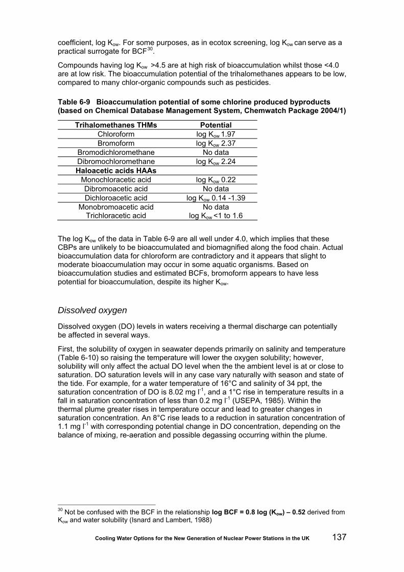
Cooling Water Options for the New Generation of Nuclear Power Stations in the UK 137
coefficient, log Kow. For some purposes, as in ecotox screening, log Kow can serve as a practical surrogate for BCF30.
Compounds having log Kow >4.5 are at high risk of bioaccumulation whilst those <4.0 are at low risk. The bioaccumulation potential of the trihalomethanes appears to be low, compared to many chlor-organic compounds such as pesticides.
Table 6-9 Bioaccumulation potential of some chlorine produced byproducts (based on Chemical Database Management System, Chemwatch Package 2004/1)
Trihalomethanes THMs Potential Chloroform log Kow 1.97 Bromoform log Kow 2.37
Bromodichloromethane No data Dibromochloromethane log Kow 2.24 Haloacetic acids HAAs
Monochloracetic acid log Kow 0.22 Dibromoacetic acid No data Dichloroacetic acid log Kow 0.14 -1.39
Monobromoacetic acid No data Trichloracetic acid log Kow <1 to 1.6
The log Kow of the data in Table 6-9 are all well under 4.0, which implies that these CBPs are unlikely to be bioaccumulated and biomagnified along the food chain. Actual bioaccumulation data for chloroform are contradictory and it appears that slight to moderate bioaccumulation may occur in some aquatic organisms. Based on bioaccumulation studies and estimated BCFs, bromoform appears to have less potential for bioaccumulation, despite its higher Kow.
Dissolved oxygen
Dissolved oxygen (DO) levels in waters receiving a thermal discharge can potentially be affected in several ways.
First, the solubility of oxygen in seawater depends primarily on salinity and temperature (Table 6-10) so raising the temperature will lower the oxygen solubility; however, solubility will only affect the actual DO level when the the ambient level is at or close to saturation. DO saturation levels will in any case vary naturally with season and state of the tide. For example, for a water temperature of 16°C and salinity of 34 ppt, the saturation concentration of DO is 8.02 mg l-1, and a 1°C rise in temperature results in a fall in saturation concentration of less than 0.2 mg l-1 (USEPA, 1985). Within the thermal plume greater rises in temperature occur and lead to greater changes in saturation concentration. An 8°C rise leads to a reduction in saturation concentration of 1.1 mg l-1 with corresponding potential change in DO concentration, depending on the balance of mixing, re-aeration and possible degassing occurring within the plume.
30 Not be confused with the BCF in the relationship log BCF = 0.8 log (Kow) – 0.52 derived from Kow and water solubility (Isnard and Lambert, 1988)

Cooling Water Options for the New Generation of Nuclear Power Stations in the UK 138
Table 6-10 Effect of temperature and salinity on DO solubility (from Turnpenny, Coughlan and Liney, 2006)
Solubility of oxygen Temperature oC Freshwater
mg l-1 Seawater (35 ppt)
mg l-1
Correction factor for salinity: factor to be subtracted
0 14.6 11.3 0.0925 5 12.7 10.0 0.0771
10 11.3 9.0 0.0653 15 10.1 8.1 0.0559 20 9.1 7.4 0.0481 25 8.2 6.7 0.0415 30 7.5 6.1 0.0362
A second effect is caused by biological and chemical oxygen demand (together sometimes known as “effective oxygen demand” or EOD) accelerated at higher temperatures. These processes are responsible for oxygen sag that is often seen during the warmer summer month in organically polluted estuaries31.
The third effect occurs when oxygen-depleted water becomes re-aerated within power stations after passing over weir or cascades (such as seal weirs) or from the action of natural draught cooling towers. Prior to the clean-up of many British rivers in the 1970s, the re-aeration action of cooling towers was shown to bring major improvements in downstream DO levels where upstream levels were under 4 mg l-1; where upstream levels were higher, small reductions in downstream DO were seen (Langford, 1990).
Depletion of DO in thermal discharge zones of any UK nuclear plants has not been a notable concern in the past, probably since none has been built on an estuary with heavy organic pollution. Where this may be a concern in any new nuclear build, appropriate water quality modelling should be carried out (see Section 6.3.4). Table 6-11 shows the draft WFD standards that will be applied to transitional and coastal waters.
Table 6-11 Draft WFD dissolved oxygen standards for transitional and coastal waters of different ecological status (UKTAG, 2008)
Freshwater Marine Fifth percentile (mg l-1)
Description
High 7.0 5.7 Protects all life-stages of salmonid fish Good 5.0-7.0 4.0-5.7 Resident salmonid fish Moderate 3.0-5.0 2.4-4.0 Protects most life-stages of non-salmonid fish Poor 2.0-3.0 1.6-2.4 Resident non-salmonid fish, poor survival of
salmonid fish Bad 2.0 1.6 No salmonid fish. Marginal survival of resident
species
Ammonia
Ammonia is present in all natural waters, generally at low concentrations that are derived primarily from mineralisation (breakdown) of organic nitrogen, denitrification
31 See e.g. Bayshore Power Plant study: http://www.westernlakeerie.org/bayshore_thermal_fish_3163b_etc.pdf

Cooling Water Options for the New Generation of Nuclear Power Stations in the UK 139
(reduction of nitrate) and excretion by aquatic organisms. However anthropogenic sources such as sewage treatment outfalls and agricultural run-off predominate in most tidal waters. Of all the water quality parameters that affect aquatic life, ammonia is probably the most important after dissolved oxygen. Concentrations are usually measured as total ammonia nitrogen (“ammonia as N”) that is an equilibrium mix of free un-ionised ammonia (NH3) and ammonium ion (NH4
+):
NH4
+ + H2O <> NH3 + H3O+ The chemical speciation of ammonia is important to its toxicity, since un-ionised ammonia is much more toxic than ammonium ion. Consequently, most ammonia regulations are written in terms of NH3 although current measurement techniques only measure total ammonia. It is therefore necessary to know the physico-chemical parameters that determine the relative proportions of the two species; these include temperature, pH, dissolved oxygen and salinity. The proportion of un-ionised ammonia, and hence toxicity, increases with pH and temperature but decreases with increasing salinity (US EPA, 1989, 1999; Alabaster et al., 1979; Moreira da Silva, 2009). Of these factors, pH is the most and salinity the least important (USEPA, 1989). In a review of the effects of ammonia on marine and estuarine organisms, Nixon et al. (1995) note that acute toxicity to fish increases at low dissolved oxygen concentrations in both fresh and saltwater. The mechanisms by which pH, temperature and salinity affect ammonia toxicity are not well understood. Although ammonium ion is not as toxic as un-ionised ammonia, it can be important when present in high concentrations: in fresh water it is thought that the pH dependence is due to joint toxicity of un-ionised ammonia and ammonium ion. Temperature affects the proportion of un-ionised ammonia and may also affect ammonia toxicity via its effects on a fish’s membrane permeability, endogenous ammonia production and other physiological processes. In freshwater the relationship between the toxicity of un-ionised ammonia and pH and temperature is similar for most species. However, in saltwater there is no evidence that temperature or salinity have a major or consistent influence on the toxicity of un-ionised ammonia. It has also been found that whilst the acute toxicity of ammonia at a given pH depends upon the fish species, chronic toxicity is more dependent on temperature. Milne (2004) proposed that the pH differential across a fish’s gills (he used rainbow trout as a model) was crucial for ammonia excretion. A fish migrating from fresh to saltwater would need either to significantly reduce its metabolic production of ammonia or the external ammonia concentration would have to be approximately one-sixth that of the freshwater. The UK Environment Agency’s catchment model SIMCAT (Environment Agency, 2008) describes the “decay” of ammonia in water with time by a first-order equation:
CkdtdC
T−=
where C is the ammonia concentration and қТ the rate constant. The rate constant is temperature dependent: 20
20 072.1 −= TT kk
Cooling water discharges can increase water temperature and salinity (if the station is fitted with desalination equipment) in the mixing zone and for some distance beyond. The slight increase in salinity might adversely affect some species even though the ammonia toxicity would decrease. Although ammonia toxicity increases with temperature, ammonia concentration would be declining through faster decay.

Cooling Water Options for the New Generation of Nuclear Power Stations in the UK 140
Alkalinity and pH
The carbonate-bicarbonate equilibria that determine pH and alkalinity in seawater are slightly influenced by temperature, with a 0.0114 pH unit change per degree Celsius (Gieske, 1969). Shifts in the equilibrium position associated with temperature rise will be reversible once the temperature falls as a result of heat loss and mixing. Any effect outside the mixing zone will therefore be localised and negligible with respect to ecological effects.
Salinity
Salinity differences associated with the CW discharge could arise from:
• discharge of cooling water abstracted from a region where salinity differs from that of the receiving water;
• concentration of salts in purge water from seawater cooling towers (indirect cooling only);
• concentration of salts within any desalination facility provided to supply freshwater to the site.
In any of these cases the associated salinity change would be small and unlikely to be detectable beyond the mixing zone.
Heavy metals
Langford (1990, p.98-99) refers to cases of zinc and copper contamination in discharges from US power plants and although copper alloys have been used in the UK, the use of titanium in modern CW condensers eliminates this source. Titanium itself does not dissolve in seawater and presents no toxic risk. Other sources of heavy metals at large power stations relate principally to burning fossil fuels and scrubbing the resulting flue-gases, therefore are not associated with nuclear generation.
Any use of copper elsewhere in the cooling system, for example in screenwell surface treatments or within intake screen materials (Cu/Ni alloy) would potentially give rise to copper within the discharge but dissolution rates are low. Prior to the use of Cu/Ni screens at the new Thames Gateway Desalination Plant (Thames Water Utilities Ltd), an investigation of copper levels in the screened water showed undetectable levels and led to approval of their use by the Drinking Water Inspectorate.
Speciation of contaminants
Changes in water temperature, along with other associated water quality changes (such as DO, pH) are known to affect the speciation and biological availability of contaminants held within bed sediments. Where a thermal discharge enters a heavily urbanised estuary or coastal water body, this aspect may need to be considered. For example, a recent study undertaken in Long Island Sound, New York by Beck and Sañudo-Wilhelmy (2007), showed that copper cycling between sediments and the water column varied seasonally, concentrations of labile copper showing a positive correlation with water temperature and a negative correlation with DO. The authors suggest that warming could increase the biological availability of copper.

Cooling Water Options for the New Generation of Nuclear Power Stations in the UK 141
Suspended sediments
The settling rate of sediments in water is described by Stoke’s Law, which includes terms of water density and viscosity, both of which are influenced by temperature. In theory, therefore, rates of sedimentation could be affected by water temperature in a thermal discharge. In practice, however, the presence of the outfall structure and the potential scouring effects associated with discharge currents are likely to outweigh settlement rate effects. It is significant that Langford’s (1990) treatise on thermal discharge effects makes reference in this context only to scour effects.
Eutrophication
Higher water temperatures may accelerate nutrient cycling and growth rates of algae. This may raise concerns over development of eutrophic algal blooms, including those of toxic species. Development of large mats of blue-green algae around the Turkey Point plant outfall in Florida was associated with the thermal discharge but blue-greens favour temperatures in the mid-thirties Celsius (GESAMP, 1990) and are therefore unlikely to develop in UK coastal waters where ΔT values are kept below the WFD uplift standard of 3oC. Entrainment passage of algae within the cooling water will depress viable algal numbers within the plume, which will offset any tendency for greater numbers due to nutrient and warming effects. Langford (1990) found no evidence of toxic algal blooms being enhanced by any thermal discharge. In a review of thermal discharge effects on the marine environment, GESAMP (1984) identified major shifts in algal community composition only in association with ΔT values of 7 to 10oC, well above values that would be allowable in UK waters beyond the mixing zone.
Microbial activity
The activity of waterborne bacteria and fungi generally increases with water temperature, leading for instance to the enhanced biological oxygen demand mentioned above. Like communities of other organisms, microbial community structure shifts according to temperature, reflecting the preferences and tolerances of different species within the mix (Langford, 1990). In addition to effects on DO level, the consequences of such changes may include changes in prevalence of human and fish/shellfish pathogens, notably Vibrio spp. and pathogenic amoebae. Human pathogens would be of most concern for discharges close to bathing beaches or areas used for water-contact sports and recreation. Fish/shellfish pathogens such as Vibrio, in the context of cooling water, primarily become a problem when the warm water is used for aquaculture. The combination of high stock densities, higher temperature and high organic loadings creates favourable conditions for pathogens to flourish.
In power stations that use chlorine-related products for biofouling control, the presence of oxidant residues in the discharge will act as a disinfectant and reduce pathogen levels, much as occurs when sewage effluents are chlorinated to reduce pathogen risk on bathing beaches.
6.3.4 Thermal discharge modelling
It has been the practice for many years for new power station developments to model the spatial and temporal characteristics of the heat fields, and sometimes other water quality characteristics, within the receiving waters. Modelling provides data for assessing the environmental effects of the discharge and for predicting regulatory

Cooling Water Options for the New Generation of Nuclear Power Stations in the UK 142
compliance with water quality standards. This will undoubtedly be a requirement for new nuclear stations.
This section gives an overview of the computational/mathematical models available to predict the thermal and chemical impacts of cooling water discharges. The exact modelling requirements of thermal and chemical discharges will be site-specific (such as consideration of the spring-neap tidal cycles for discharges into coastal waters) and seasonal effects will be considered. This section discusses the general role of modelling and readily available models, including their suitability for different water environments. The pros and cons of models are outside the scope of this overview.
Role of modelling
Modelling can be used to predict the potential water quality and thermal impacts of cooling water discharges on the water environments under various ambient conditions (such as tides, seasonal river flows, water quality and temperature). It can aid the design of cooling water systems (such as discharge configurations and operating conditions, optimization of cooling water intakes in terms of water temperature and silt content). Modelling also enables the necessary mitigation measures to be adopted.
Modeling predictions can be used to inform BAT (best available techniques) analysis. Modelling allows comparison between different cooling water options. For example, models can be used to simulate the fate of excess chlorine from discharged cooling water (biocide in the form of added chlorine or electro-hypochlorination) and concentrated brine plume as a byproduct of electro-hydrochlorination. Predictions can be used to compare the environmental impact of different antifouling options.
Type of models
Models for predicting the water quality and thermal impacts of discharges into water environments consist of a hydrodynamic module and water quality module. The hydrodynamic module predicts the flows and depth of water across the modelled area. It provides the hydrodynamic information necessary to simulate advection and dispersion of pollutants by the water quality module. Most water quality modules simulate the chemical reactions that take place within the water body. Some also simulate the biological fates of pollutants (such as decay of E. Coli) and pollutants’ chemical behaviour between water and sediment phases (such as metal partitioning).
Available methods range from simple dispersion calculations to sophisticated and computationally intensive models. Some models are designed for the initial dilution and mixing zone analysis in the near field of a discharge while others are designed to simulate the advection and dispersion of heat and chemicals beyond the mixing zone.
Models vary in terms of the physical and chemical processes they can simulate and also the dimensionality of models. For example, the configuration of discharges (or the discharge momentum) has a considerable effect on the density currents. Thermal discharges affect the density of currents as well as other water quality parameters (such as reactions rates of water chemistry, primary productivity and nutrient cycling). Saline discharges also affect density currents. Some models account for the aforementioned effect of thermal and saline discharges explicitly while others do not.
Models vary in their dimensionality. There are 1-D (one-dimensional), 2-D (two-dimensional) horizontal, 2-D vertical and 3-D (three-dimensional) models. A 1-D model covers a length scale, normally down the middle section of a river channel or estuary. The choice of a 1-D model assumes that the water is well mixed laterally and vertically.

Cooling Water Options for the New Generation of Nuclear Power Stations in the UK 143
A 2-D model covers two length scales, which can be along the length and width of a river channel/estuary (a 2-D horizontal model, assuming the water body is well mixed vertically but not laterally), or along the length and depth of a river channel/estuary (a 2-D vertical model, assuming the water body is well mixed laterally but not vertically). A 3-D model covers the length, width and depth of a water body.
The model chosen for a study should be suitable to answer the questions posed in the study and appropriate to the situation it is applied to. Furthermore, a model needs to be calibrated and validated before its predictions can be relied on in decision-making.
Initial dilution and mixing zone models
H1 dilution factors IPPC H1 guidance (Environment Agency, Environment and Heritage Service and Scottish Environment Protection Agency, 2003; Environment Agency, 2008a; Environment Agency, 2009a) gives simple methods of estimating the impacts of discharges on water environments. Simple mass balance equations using dilution factors are given for discharges of chemical substances to inland rivers, freshwater- and saline-dominated parts of estuaries, and coastal waters (see Table 6-12). H1 also gives details of direct toxicity assessment techniques to assess impacts of highly complex discharges (for example, when the chemical composition is not known).
Table 6-12 Simple mass-balance equations for discharges to various water environments (Environment Agency, Environment and Heritage Service, Scottish Environment Protection Agency, 2003; Environment Agency, 2008a; Environment Agency 2009a)
Water environment Mass-balance equation Inland rivers
1000xRFREFRRCxEFRPC
+=
Freshwater-dominated parts of estuaries 1000x
DRERCxEFRPC =
Coastal waters or saline-dominated parts of estuaries
10003/2
xDRC
RCxEFRPC =
where PC = concentration (μg l-1) of chemical substance in rivers from cooling water discharge (process contribution without taking into account background conc.) EFR = flow rate of cooling water discharge (m3 s-1) RC = concentration (mg l-1) of chemical substance in the cooling water discharge RFR = river flow rate (m3 s-1). DRE = Dispersion rate (m3 s-1) of the fresh-water dominated parts of estuaries = 2.4 for low nominal dilution conditions = 5 for medium nominal dilution conditions = 10 for high nominal dilution conditions
DRC = Dispersion rate (m2 s-2/3) of coastal waters or saline-dominated estuary = 2.5 for low nominal dilution conditions in coastal waters = 8 for medium nominal dilution conditions in coastal waters = 25 for high nominal dilution conditions in coastal waters = 2.4 for low nominal dilution conditions in saline-dom. parts of estuaries = 5 for medium nominal dilution conditions in saline-dom. parts of estuaries = 15 for high nominated dilution conditions in saline-dom. parts of estuaries

Cooling Water Options for the New Generation of Nuclear Power Stations in the UK 144
The mass balance equation given in Table 6.12 for inland rivers can be used for impact assessments other than the initial dilution analysis. Equations for freshwater-dominated parts of estuaries, coastal waters and saline-dominated parts of estuaries are for the derivation of the 95th percentile initial dilution (reduction in concentration the discharge will receive between point of release and open sea surface for 95 per cent of the time).
ELSID ELSID has been developed by the Environment Agency to calculate dilutions of discharges into still or tidal waters. It performs Monte-Carlo simulations of initial dilution to calculate the 95th percentile compliance (Scottish Environment Protection Agency, 2006).
VISUAL PLUMES (VP) Visual Plumes (VP) is a Windows-based mixing zone modelling application developed by the US EPA (United States Environmental Protection Agency). It is designed to replace the DOS-based PLUMES program. Like PLUMES, VP can be used for plumes discharged into fresh and marine waters.
VP supports initial dilution models that simulate surface water jets, single and merging submerged plumes in arbitrarily stratified ambient flows. Predictions include dilution, rise, diameter, and other plume variables. VP has a bacterial decay model and a conservative tidal background pollutant build-up capability. Hence it is useful for mixing zone analyses and water quality applications.
CORMIX CORMIX (CORnell MIXing Zone Expert System) is a model for the analysis, prediction and design of chemical and thermal discharges into all types of ambient water bodies, including small streams, large rivers, lakes, reservoirs, estuaries and coastal waters. The model focuses on predictions of the geometry and dilution characteristics of the initial mixing resulting from different discharge configurations so that compliance with regulatory constraints can be evaluated. It can be used to simulate near-field thermal effects/temperature distribution of submerged single-port discharges (CORMIX 1), submerged multiport diffuser discharges (COMIX2) and buoyant surface discharges (CORMIX 3). It also predicts plume behaviour at large distances and can be used as a first-order screening and design tool. However, it does not simulate explicitly changing conditions such as tides.
CFX-5 A more recent development has been the ability to use 3-D computational fluid dynamics models such as the ANSYS CFX-5™ model, such models now being capable of handling free-surface flows. Though more costly, they are subject to fewer constraints and offer a flexible approach to evaluating plume behaviour with different outfall configurations.
Beyond the mixing zone A wide range of models are available for the simulation of thermal and water quality impacts beyond the mixing zone of discharges. They vary in complexity and range of applications. Most models use a hydrostatic pressure assumption in modelling flows. Unless the predictions from a mixing zone model are used as inputs to these models, this hydrostatic assumption can result in inaccurate predictions of the thermal and

Cooling Water Options for the New Generation of Nuclear Power Stations in the UK 145
water quality impacts of buoyant plumes not only in the mixing zone, but also outside the mixing zone and well beyond.
WARNB, MCARLO and AMMONIA WARNB (Warn-Brew Method) and MCARLO (Monte-Carlo Simulation) are computer programs publicly available from the Environment Agency. They use mass-balance equations and combining distributions to calculate the river quality downstream of a continuous discharge or the discharge quality required to achieve specific water quality targets in rivers (Environment Agency, 2009b). The water quality determinands considered include Biochemical Oxygen Demand (BOD) and Total ammonia. WARNB assumes that the data distributions are log-normal while MCARLO can be applied to other types of data distributions. AMMONIA uses mass balance equations, Monte-Carlo simulation and water chemistry data to calculate the impact of discharges on un-ionised ammonia and total ammonia in rivers (Environment Agency, 2009b).
SIMCAT SIMCAT is a mathematical model developed by the Environment Agency to calculate the impact of discharges and diffuse inputs into inland rivers on water quality throughout a catchment (Environment Agency, 2008b). It is a one-dimensional, steady state model. It uses Monte-Carlo simulations to mix discharges and diffuse inputs with river waters and then routes flow in the river down through the catchment, applying water quality transformation processes en route.
SIMCAT can be used to model concentrations of chloride, biochemical oxygen demand, total organic carbon, ammonia, dissolved oxygen, phosphate and nitrate. SIMCAT does not simulate river temperature directly but temperature is used to adjust the rate of natural purification, saturation concentrations of dissolved oxygen and decay rate of biochemical oxygen demand, ammonia and so on. It calculates summary statistics of water quality like means and percentiles, allowing the predictions to be compared directly with water quality standards defined as means and percentiles.
ISIS Water Quality ISIS Water Quality (developed by HR Wallingford and available from Halcrow) is a module add-on to ISIS Professional that can be used to model the advection/diffusion of conservative and decaying pollutants, water temperature, cohesive sediment transport, interaction of quality determinands with sediments, phytoplankton and pH. It can be used for water quality studies in rivers.
QUAL2K QUAL2K (or Q2K) is a river and stream water quality model developed by the US EPA. It is a modernized version of the model QUAL2E. QUAL2K simulates point and non-point loads and abstractions of heat and mass. It can be used to simulate conventional pollutants (such as nitrogen, phosphorus, dissolved oxygen, BOD), pH, pathogens and periphyton.
MIKE MIKE11, MIKE21 and MIKE3 are modelling systems developed by DHI (Danish Hydraulic Institute) for hydrodynamic modelling. MIKE11 (a one-dimensional modelling system) can be used for rivers and reservoirs or lakes if it is coupled with a module MIKE11 Stratified. MIKE21 (a two-dimensional modelling system) and MIKE3 (a three-dimensional modelling system) are ideally suited for marine environment (estuaries, coastal waters and sea). MIKE3 can also be used for lakes (stratified waters). The

Cooling Water Options for the New Generation of Nuclear Power Stations in the UK 146
non-hydrostatic pressure formulation of MIKE3 hydrodynamic module allows for an accurate simulation of vertical acceleration of flows. This would improve predictions of the impact of thermal discharges both within and outside the mixing zone.
The basic hydrodynamic models of MIKE coupled with various modules can be used to simulate physical, chemical or biological processes in the water environment. The AD (advection-dispersion) module is typically used in cooling water studies to simulate the transport, dispersion and decay of dissolved or suspended substances. ECO Lab is a module for ecological modelling that can be coupled to MIKE11, MIKE21 and MIKE3. The ECO Lab integrated AD Module also calculates the salinity and water temperature.
WASP WASP/DYNHYD is a US EPA generalized modelling framework that simulates the transport of heat and fate of contaminant (biochemical oxygen demand, dissolved oxygen dynamics, nutrients, bacterial contamination and toxic chemical movement) in surface waters. The DYNHYD model is a simple hydrodynamic model that simulates variable tidal cycles, wind, and unsteady inflows. It produces an output file that can be linked with WASP (Water Quality Analysis Simulation Program) to supply the flows and volumes to the water quality model. WASP can be applied in one, two, or three dimensions. Hence it can be used to simulate the water quality impact of discharges into rivers, lakes, reservoirs, estuaries, coastal waters and sea.
DELFT3D DELFT3D is a multi-dimensional (two- or three-dimensional) modelling system developed by Delft Hydraulics. It can be used to simulate the advection and dispersion of heat and chemicals discharged via cooling waters into fluvial, estuarine and coastal environments. It calculates non-steady flow and transport phenomena resulting from tidal and meteorological forcing. Areas of application of DEFT3D include salt intrusion, cooling water intakes, transport of dissolved materials and pollutants, tidal and wind driven flows, stratified and density driven flows. DELFT3D can simulate thermal discharge, effluent discharge and intake of cooling water at any location and depth.
DELFT3D can simulate a wide range of substances (such as chloride/salinity, oxygen, biochemical oxygen demand, excess temperature) and water quality processes (such as chemical processes, transport of dissolved substance towards the bottom, sedimentation and re-suspension of particulates).
Its non-hydrostatic assumption in the flow module allows for accurate predictions of vertical distributions of temperature and pollutant concentrations when the plumes are buoyant. This would produce more accurate predictions in the mixing zone.
TELEMAC 2D/3D TELEMAC, developed by the Laboratoire National d'Hydraulique (a department of Electricité de France's Research and Development Division), is a modelling system for the simulation of physical processes associated with rivers, estuaries and coastal waters. TELEMAC comprises modules for hydrodynamics (TELEMAC-2D/TELEMAC-3D), water quality (WQ 2D/3D), sediment transport, dispersion of pollutants and wave dynamics. It represents a comprehensive range of water quality processes. TELEMAC can be used for dispersion studies of positively-buoyant (such as fresh or heated effluent discharged into the sea) or negatively-buoyant (such as cold or high-salinity effluent discharged into the sea) discharges.

Cooling Water Options for the New Generation of Nuclear Power Stations in the UK 147
THREETOX THREETOX is a three-dimensional modelling system developed by the National Academy of Sciences of Ukraine for simulating hydrodynamics, salinity and thermal transport in lakes, reservoirs, estuaries and coastal ocean. It can also be used to model sediment and radionuclide transport, including the non-equilibrium partitioning of radionuclide in the water and sediment phases.
Key model input parameters
Model input parameters depend on the model used and predictions required from the model. Table 6-13 shows a checklist of the key input parameters for modelling the effects of thermal and TRO (from the use of biocides) discharges. Model predictions are expected to be sensitive to these parameters.
Table 6-13 Key model input parameters
Parameters Reasons for importance Relevance Relating to the receiving water environment River cross sections and depths
Affecting flows For river models.
Bathymetry of lakes, estuaries, coastal waters, sea
Affecting flows For models of lakes, estuaries, coastal waters and seas.
Flows and tidal heights at model boundaries
Affecting flows For models of estuaries, coastal waters and seas.
Non-physical model parameters Manning’s roughness coefficient
Affecting flows Manning’s coefficient represents the resistance to flows in open channels and floodplains. Its value depends on many factors, including the bottom roughness/resistance, stage of flows, flow velocity, meandering of the channel and vegetation.
Typical values range from 0.02 (e.g. for straight uniform channels with clean beds) to 0.1 (e.g. for natural streams with very weedy reaches, flood plains with heavy stand of timber).
Eddy viscosity coefficient
Affecting the vertical and/or horizontal mixing of mass and momentum.
Used in some 3-D models (e.g. DELFT3D). It is a factor for modelling turbulence. Typical values of the vertical eddy viscosity coefficient range from 10-5 m2s-1 to 10-3 m2s-1. Values of the horizontal eddy viscosity coefficient range
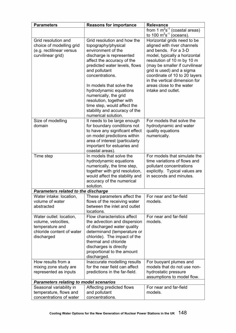
Cooling Water Options for the New Generation of Nuclear Power Stations in the UK 148
Parameters Reasons for importance Relevance from 1 m2s-1 (coastal areas) to 100 m2s-1 (oceans).
Grid resolution and choice of modelling grid (e.g. rectilinear versus curvilinear grid)
Grid resolution and how the topography/physical environment of the discharge is represented affect the accuracy of the predicted water levels, flows and pollutant concentrations. In models that solve the hydrodynamic equations numerically, the grid resolution, together with time step, would affect the stability and accuracy of the numerical solution.
Horizontal grids need to be aligned with river channels and bends. For a 3-D model, typically a horizontal resolution of 10 m by 10 m (may be smaller if curvilinear grid is used) and a sigma coordinate of 10 to 20 layers in the vertical dimension for areas close to the water intake and outlet.
Size of modelling domain
It needs to be large enough for boundary conditions not to have any significant effect on model predictions within area of interest (particularly important for estuaries and coastal areas).
For models that solve the hydrodynamic and water quality equations numerically.
Time step In models that solve the hydrodynamic equations numerically, the time step, together with grid resolution, would affect the stability and accuracy of the numerical solution.
For models that simulate the time variations of flows and pollutant concentrations explicitly. Typical values are in seconds and minutes.
Parameters related to the discharge Water intake: location, volume of water abstracted
These parameters affect the flows of the receiving water between the inlet and outlet locations.
For near and far-field models.
Water outlet: location, volume, velocities, temperature and chloride content of water discharged
Flow characteristics affect the advection and dispersion of discharged water quality determinand (temperature or chloride). The impact of the thermal and chloride discharges is directly proportional to the amount discharged.
For near and far-field models.
How results from a mixing zone study are represented as inputs
Inaccurate modelling results for the near field can affect predictions in the far-field.
For buoyant plumes and models that do not use non-hydrostatic pressure assumptions to model flow.
Parameters relating to model scenarios Seasonal variability in temperature, flows and concentrations of water
Affecting predicted flows and pollutant concentrations.
For near and far-field models.

Cooling Water Options for the New Generation of Nuclear Power Stations in the UK 149
Parameters Reasons for importance Relevance quality parameters, ambient temperatures and wind speeds Tidal variations Affecting flows and water
depths. For models of estuaries, coastal waters and seas.
Receiving water: temperature and chloride concentrations
They are the background temperature and chloride concentrations for the discharges to be mixed with.
For near and far-field models.
Meteorological conditions (wind speed and direction, ambient air temperature)
Affecting heat loss and producing wind driven current.
For models that can simulate heat loss and wind driven current.
6.3.5 Thermal preference and tolerance of biota
Recent reviews in the context of WFD requirements have been prepared on behalf of the Environment Agency (Turnpenny, Coughlan and Liney, 2006) and UKTAG (Turnpenny and Liney, 2006). Figure 6.26 provides a summary of thermal preference/tolerance data for a variety of fish species in relation to existing Freshwater Fish Directive and draft WFD temperature standards. Langford (1990) provides a useful summary of thermal effects, specifically relating to power station discharges. Thermal tolerance depends on a number of factors, including zoogeographic origins of species and habit. In the UK, species originating from warmer climates south of the British Isles towards the Mediterranean are referred to as “Lusitanian”, while those distributed primarily north of Britain are known as “Boreal” or (further north) “Arctic-Boreal” species; these are sometimes referred to as ‘warm-water’ and ‘cold-water’ species respectively. Such distinctions are not absolute, and different species together occupy a continuum from north to south. They do, however, provide useful shorthand which indicates the likely responses to thermally enriched waters. Thus, bass (Dicentrarchus labrax) is a Lusitanian species which has its northern limits around the British Isles and benefits from the warmer waters around thermal discharges. Several decades ago, bass were scarce on the east coast of Britain and the northern limit of their distribution was around Sizewell (Suffolk). The thermal discharge canal at Kingsnorth was considered an important overwintering area that allowed bass to remain further north than they otherwise would (Langford, 1983, 1987, 1990; Pawson and Eaton, 1999). With gradually increasing winter temperatures over this period, bass have spread northwards and are now regularly caught by anglers on the east coast of Scotland32. While water temperature is a factor, Langford (1990) ascribes the attractiveness of these areas to bass as much to the food supply provided by entrained fish juveniles issuing from the CW discharge. The combined effect is that young bass not only survive the winter better in heated discharges, they also benefit from faster growth and a prolonged growth season. Pawson and Eaton (1999) argue that these benefits more than compensate for losses of young bass to impingement on the CW intake screens at Kingsnorth, which amounted to around 15 per cent of the available population in the autumn/winter of 1987 and 1988. So important are thermal discharges to juvenile bass in the UK that in 1990, MAFF established protected nursery areas around the larger estuarine and coastal power station thermal discharges in England and Wales33.
32 See e.g. www.worldseafishing.com/forums/archive/index.php?t-2203.html (viewed 10/02/09) 33 The Bass (Specified Sea Areas) (Prohibition of Fishing) Order 1990: SI 1990 No.1156

Cooling Water Options for the New Generation of Nuclear Power Stations in the UK 150
Certain economically important shellfish are also of Lusitanian origin. Langford (1990) cites a number of examples of UK shellfish benefiting from, or at least thriving alongside, thermal discharges. The native European oyster (Ostrea edulis) favours warmer waters. Optimum feeding and growth in O. edulis occurs at a water temperature of about 20-25oC, which is close to the upper ambient seawater temperature found in British coastal waters (Buxton et al. 1981). During the 1970s, its largest UK fishery was in the Solent, alongside the outfall from Fawley power station when it was operating at base-load. The Solent stock subsequently declined as power plant use became infrequent, the collapse due principally to overfishing. Similarly, the American hard-shell clam (Mercenaria mercenaria) thrived in the vicinity of the old Marchwood power station in Southampton Water, reaching unusually high population densities which then spread to areas outside the thermal field; following the closure of the plant, its stocks also declined, accelerated by overfishing. In these cases, biological detritus from entrained plankton may have contributed to the success of these stocks. Another interesting example more directly attributable to temperature is the improved survival of native oysters in the Blackwater Estuary next to the Bradwell thermal discharge observed after the exceptionally cold winter of 1962-3 (Figure 6-27).

Cooling Water Options for the New Generation of Nuclear Power Stations in the UK 151
4 6 8 10 12 14 16 18 20 22 24 26 28 30 32 34 36 38 40
Temperature °C
Optimal growth temperatureUltimate preferendum Lethal temperature
Sea lampreyRiver lampreyAllis shadTwaite shadSpratSea bassDaceSand smeltDover soleFlounderEelSand goby
Dab
PlaiceSmeltSalmonSea/brown troutPoutingWhitingNilsson's pipefishPoggeHerring larvaeHerring juvenile
21.5 °C 28 °C20°C 23°C 28°C
Figure 6-26 Temperature preferenda, optimal growth temperatures and lethal temperatures for key UK fish species. Current UK water temperature standards are indicated by dashed vertical black lines. Suggested WFD boundaries are shown by dashed vertical coloured lines: green, high/good; blue, good/mod; orange, mod/poor.
LUSI
TAN
IAN
A
RC
TIC
-BO
REA
L

Cooling Water Options for the New Generation of Nuclear Power Stations in the UK 152
Figure 6-27 Mortality of oysters in the River Blackwater, Essex, following the severe winter of 1962-63 (Turnpenny and Coughlan, 2003)
The corollary of this zoogeographic effect is that species with more Arctic-Boreal origins which find themselves at the southern limits of their distribution in Britain may be excluded from heated areas. Members of the herring, cod and salmon families would fall into this category. However, the exclusion of a species from the relatively small area affected by a thermal discharge will in most cases be less ecologically significant than the foothold given to warm-water species by a thermal discharge. Problems could conceivably arise, however, if the plume or long-term thermal field affected a large part of a local habitat. Examples might include discharges affecting the benthic spawning grounds of herring (Clupea harengus), such as the Eagle Bank near to the Bradwell nuclear site, or the localised areas favoured by smelt (Osmerus eperlanus) in the middle zone of the Thames Estuary.
Species of intertidal habit are naturally adapted to wide fluctuations of temperature. Solar heat input affects the surface layers of all natural waters. In estuaries the heating and cooling of mudflats and other intertidal areas can cause strongly fluctuating temperatures on a tidal/diurnal timescale. The effects are most marked where intertidal areas form a high proportion of the total estuary area and in summer (this is particularly marked in estuaries where freshwater run-off and exchange is low and low water of high range tides occurs around midday). On clear, still summer nights significant re-radiation of heat can occur, at times resulting in local ground-frost. Spencer (1970) recorded a 15 oC variation in the near-surface temperature of a Milford Haven (Dyfed) mudflat over a 48-hour period in September 1968 but only 3oC in March of that year. In the Blackwater estuary (Essex) the heat rejected by Bradwell 300 MWe nuclear power station was equivalent to about 20 per cent of the incoming solar radiation on an average summer’s day but about 200 per cent on an average winter’s day. It was calculated that for every 3 oC through which the top 10 mm of mudflat was cooled by

Cooling Water Options for the New Generation of Nuclear Power Stations in the UK 153
the returning tide, a quantity of heat equivalent to that rejected by the power station in one hour was rapidly transferred to the water (Hawes et al.1974).
The tolerance of an organism to a particular temperature regime will depend on the temperature to which it has become acclimatised. Thus, if an animal has adjusted to a low temperature regime and is transferred to higher temperatures, it will not cope as well as if it has had time to adapt its metabolic processes to the higher temperatures. This has limited significance for thermal discharges, as associated sudden temperature changes are seldom more than a few degrees Celsius; however, it is important to consider the relevant acclimation temperature when considering the applicability of temperature preference/tolerance results published from laboratory studies.
6.3.6 Effects of thermal discharges on marine benthos
Thermal discharges can only affect planktonic species as the effluent mixes with the receiving water and thus dilutes; as a consequence, such effects are negligible. Equally, nektonic/pelagic species, when not spatially constrained, can detect and avoid such effluent plumes if they are perceived to be deleterious. Conversely, the marine benthos is not as mobile as the nekton, and will receive the direct impact of the effluent where that water impinges on the sea bed or shore. It is thus the benthos which is most susceptible to effects of the thermal discharge. In practice, as the CW effluent water is normally less dense than the receiving water, it rises to the surface and away from the seabed where possible. Thus, any impact on the benthos is restricted to that area of direct impingement.
Species of the marine benthos will react differently to these aspects of the effluent regime, depending on their pre-adaptation to such conditions. In temperate waters in the northern hemisphere, species with a more southerly natural distribution will be more tolerant of generally higher temperatures; for example, species with a Lusitanian distribution will be more tolerant than those with a Boreal distribution. Species near the southern limit of their distribution (in the northern hemisphere) are more likely to be affected deleteriously by the thermal conditions of a CW effluent.
Species inhabiting the littoral zone are naturally exposed to greater ranges and extremes of temperature than those restricted to the sublittoral. While, when covered by the tide, the shore temperature will reflect that of the water, once uncovered exposure to insolation, wind and frost can lead to a radical and rapid change in temperature. During summer low tides in Milford Haven, Spencer (1970) measured temperature rises on the uncovered sand-flats of 0.2ºC min-1, with a temperature range in September (1966) of 15 to 26ºC on the shore, compared with an ambient water temperature of 16.5ºC. On the mud-flats of the Medway Estuary (adjacent to the Thames) Walters (1977, in Bamber, 1990) measured an annual range from -4.5ºC to 32.5ºC.
The higher the shore zone, the longer the exposure to atmospheric (rather than aquatic) conditions, and thus the more extreme the conditions described above. As a result, the species which inhabit this zone are tolerant of (and adapted to) such temperature variations (within natural timescales).
Owing to the differential tolerance of species up the shore, the overall effect of these thermal stresses tends to be the moving down-shore of littoral zones, to the point of replacement of infralittoral and sublittoral species by those more tolerant species from the littoral (Bamber and Spencer, 1984).
There is also evidence that estuarine species, and those of coastal saline lagoons, are more tolerant of thermal stress than fully marine species (for example, Idotea chelipes versus I. emarginata: Naylor, 1965).
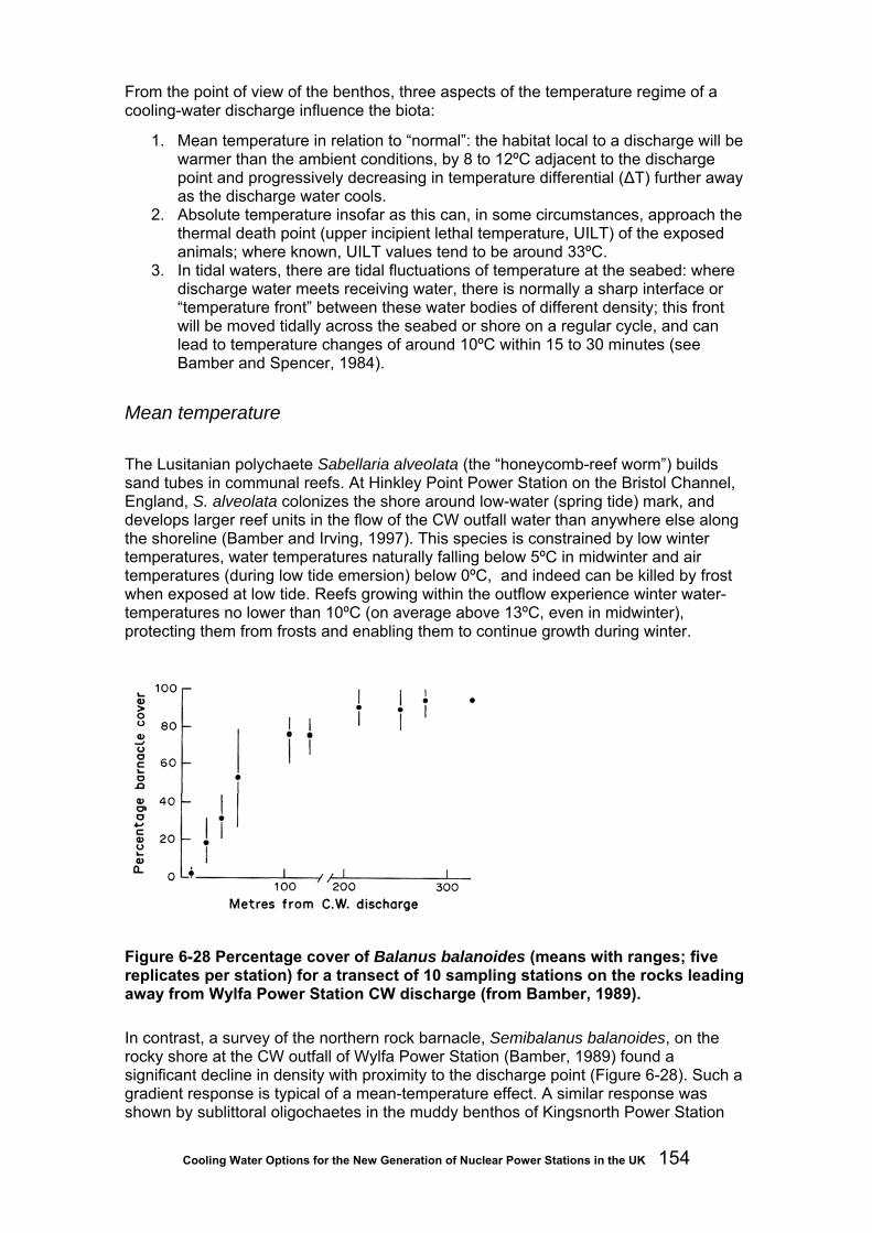
Cooling Water Options for the New Generation of Nuclear Power Stations in the UK 154
From the point of view of the benthos, three aspects of the temperature regime of a cooling-water discharge influence the biota:
1. Mean temperature in relation to “normal”: the habitat local to a discharge will be warmer than the ambient conditions, by 8 to 12ºC adjacent to the discharge point and progressively decreasing in temperature differential (ΔT) further away as the discharge water cools.
2. Absolute temperature insofar as this can, in some circumstances, approach the thermal death point (upper incipient lethal temperature, UILT) of the exposed animals; where known, UILT values tend to be around 33ºC.
3. In tidal waters, there are tidal fluctuations of temperature at the seabed: where discharge water meets receiving water, there is normally a sharp interface or “temperature front” between these water bodies of different density; this front will be moved tidally across the seabed or shore on a regular cycle, and can lead to temperature changes of around 10ºC within 15 to 30 minutes (see Bamber and Spencer, 1984).
Mean temperature
The Lusitanian polychaete Sabellaria alveolata (the “honeycomb-reef worm”) builds sand tubes in communal reefs. At Hinkley Point Power Station on the Bristol Channel, England, S. alveolata colonizes the shore around low-water (spring tide) mark, and develops larger reef units in the flow of the CW outfall water than anywhere else along the shoreline (Bamber and Irving, 1997). This species is constrained by low winter temperatures, water temperatures naturally falling below 5ºC in midwinter and air temperatures (during low tide emersion) below 0ºC, and indeed can be killed by frost when exposed at low tide. Reefs growing within the outflow experience winter water-temperatures no lower than 10ºC (on average above 13ºC, even in midwinter), protecting them from frosts and enabling them to continue growth during winter.
Figure 6-28 Percentage cover of Balanus balanoides (means with ranges; five replicates per station) for a transect of 10 sampling stations on the rocks leading away from Wylfa Power Station CW discharge (from Bamber, 1989). In contrast, a survey of the northern rock barnacle, Semibalanus balanoides, on the rocky shore at the CW outfall of Wylfa Power Station (Bamber, 1989) found a significant decline in density with proximity to the discharge point (Figure 6-28). Such a gradient response is typical of a mean-temperature effect. A similar response was shown by sublittoral oligochaetes in the muddy benthos of Kingsnorth Power Station

Cooling Water Options for the New Generation of Nuclear Power Stations in the UK 155
discharge canal (River Medway, Kent, England). A three-year survey of monthly sampling at six sites down the four-km length of the canal (Bamber and Spencer, 1984) found the common estuarine species Tubificoides benedii to show a gradient of decline from the control site (DC4) to the vicinity of the discharge headworks (N5), while, by contrast, the congeneric T. amplivasatus increased towards the headworks (Figure 6-29).
Figure 6-29 Monthly densities of A – Tubificoides amplivasatus and B – T. benedii in the CW discharge canal of Kingsnorth Power Station, at six sampling sites reflecting a gradient of mean ΔT from 9.2ºC at N5 to 0ºC at DC4 (after Bamber and Spencer, 1984) A similar congeneric contrast by sympatric barnacle species in response to higher mean water temperature at a CW outfall was found by Straughan (1980a, b): on the shores at thermally affected sites in both Estero Bay and King Harbour, California, USA, the warmer-water, more southern species Chthamalus fissus was favoured over the more northern, cooler-water species C. dalli.
Absolute temperature
Examples of absolute temperature effect are less easy to detect, as they will commonly be expressed as an absence of a species, and thus less clearly detectable. During the study of the Kingsnorth Power Station outfall benthos mentioned above (Bamber and Spencer, 1984), one of the more abundant species of the littoral and infralittoral mud was the amphipod Corophium volutator. This species has been shown to become hyperactive at higher temperatures, and will leave its tubes to swim upwards into the water column at temperatures over 25ºC (Gonzales and Yevitch, 1977). In spring and
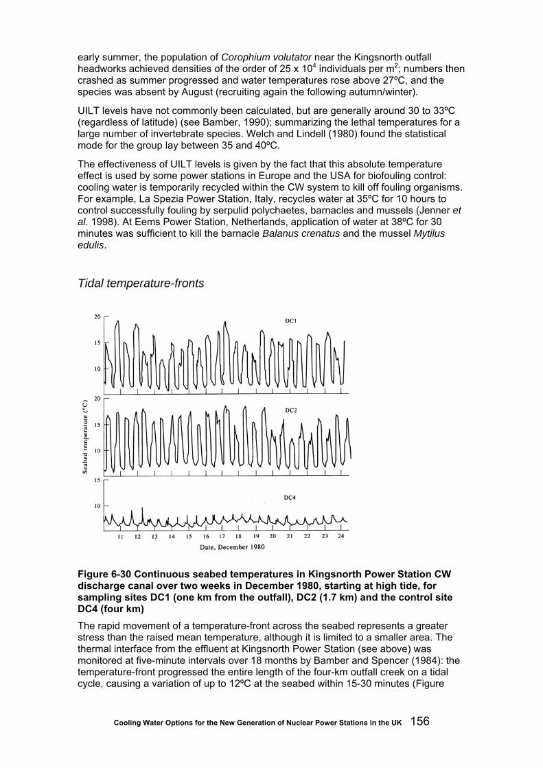
Cooling Water Options for the New Generation of Nuclear Power Stations in the UK 156
early summer, the population of Corophium volutator near the Kingsnorth outfall headworks achieved densities of the order of 25 x 104 individuals per m2; numbers then crashed as summer progressed and water temperatures rose above 27ºC, and the species was absent by August (recruiting again the following autumn/winter).
UILT levels have not commonly been calculated, but are generally around 30 to 33ºC (regardless of latitude) (see Bamber, 1990); summarizing the lethal temperatures for a large number of invertebrate species. Welch and Lindell (1980) found the statistical mode for the group lay between 35 and 40ºC.
The effectiveness of UILT levels is given by the fact that this absolute temperature effect is used by some power stations in Europe and the USA for biofouling control: cooling water is temporarily recycled within the CW system to kill off fouling organisms. For example, La Spezia Power Station, Italy, recycles water at 35ºC for 10 hours to control successfully fouling by serpulid polychaetes, barnacles and mussels (Jenner et al. 1998). At Eems Power Station, Netherlands, application of water at 38ºC for 30 minutes was sufficient to kill the barnacle Balanus crenatus and the mussel Mytilus edulis.
Tidal temperature-fronts
Figure 6-30 Continuous seabed temperatures in Kingsnorth Power Station CW discharge canal over two weeks in December 1980, starting at high tide, for sampling sites DC1 (one km from the outfall), DC2 (1.7 km) and the control site DC4 (four km) The rapid movement of a temperature-front across the seabed represents a greater stress than the raised mean temperature, although it is limited to a smaller area. The thermal interface from the effluent at Kingsnorth Power Station (see above) was monitored at five-minute intervals over 18 months by Bamber and Spencer (1984): the temperature-front progressed the entire length of the four-km outfall creek on a tidal cycle, causing a variation of up to 12ºC at the seabed within 15-30 minutes (Figure

Cooling Water Options for the New Generation of Nuclear Power Stations in the UK 157
6-30, DC1, DC2). At the control site (Figure 6-30, DC4) a residual front of 3ºC was found on the first flood of the recirculating tide.
As a result, the number of species present at each of four studied sites along the length of the creek was consistently half of that at the control site (Figure 6-31), irrespective of the gradient of mean temperature (see above). The species not eliminated by this interface stress were all species whose range included the littoral zone, species naturally more tolerant of temperature fluctuation.
Figure 6-31 Numbers of benthic infaunal species in Kingsnorth Power Station CW discharge canal over three years; sampling sites K1 and DC1 to DC3 are within the canal, DC4 is the control site (after Bamber and Spencer, 1984) Equally, the results from the control site indicate that a tidally-moving thermal-front of up to 3ºC was tolerable to these species.
Summary of effects on the benthos
The above examples show that warmer-water species are more tolerant of higher-temperature stresses than colder-water species, and that species whose distribution includes the littoral zone are more tolerant than those from the sublittoral. This is further demonstrated on rocky shores adjacent to thermal effluents by a downward shift of classical zonation (see Straughan, 1980a, b; Bamber and Coughlan, 1987).
The interrelationship between this evolutionary history, potentially resulting in some preadaptation to thermal effluent temperature conditions, and the three main stress parameters of those conditions (mean, absolute, and fluctuation in temperature) will govern the response of marine organisms to power-station CW discharges. Other than at outfall systems of a semi-enclosed configuration, thermal effects can be found within 200 to 500 m of the discharge, with some subtle effects a little further afield. Within this affected range, it can be predicted that eurythermal species from the littoral, from estuaries and coastal lagoons, and/or those from warmer biogeographic ranges will be unaffected or favoured until UILTs are reached, while stenothermal species from the sublittoral, fully marine and/or cooler biogeographic areas will be deleteriously affected. The extent and degree of any impact (deleterious or otherwise) will be proportional to the volume, velocity and ΔT of the discharged effluent, other things being equal.
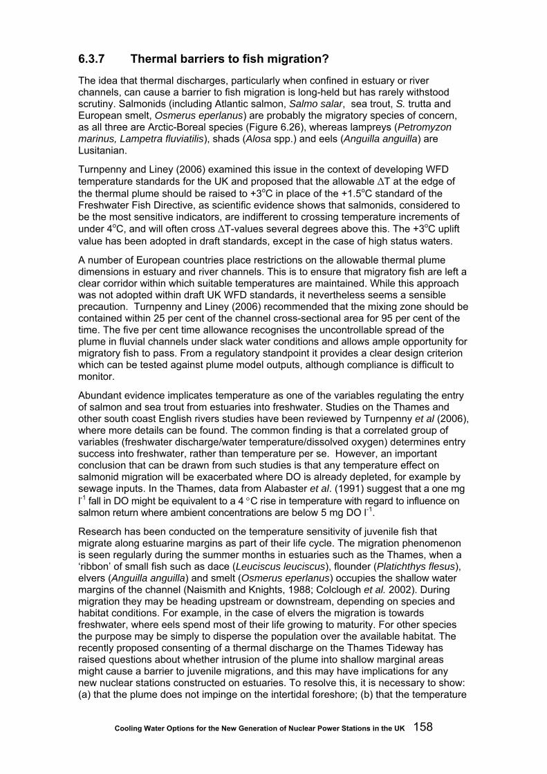
Cooling Water Options for the New Generation of Nuclear Power Stations in the UK 158
6.3.7 Thermal barriers to fish migration?
The idea that thermal discharges, particularly when confined in estuary or river channels, can cause a barrier to fish migration is long-held but has rarely withstood scrutiny. Salmonids (including Atlantic salmon, Salmo salar, sea trout, S. trutta and European smelt, Osmerus eperlanus) are probably the migratory species of concern, as all three are Arctic-Boreal species (Figure 6.26), whereas lampreys (Petromyzon marinus, Lampetra fluviatilis), shads (Alosa spp.) and eels (Anguilla anguilla) are Lusitanian.
Turnpenny and Liney (2006) examined this issue in the context of developing WFD temperature standards for the UK and proposed that the allowable ΔT at the edge of the thermal plume should be raised to +3oC in place of the +1.5oC standard of the Freshwater Fish Directive, as scientific evidence shows that salmonids, considered to be the most sensitive indicators, are indifferent to crossing temperature increments of under 4oC, and will often cross ΔT-values several degrees above this. The +3oC uplift value has been adopted in draft standards, except in the case of high status waters.
A number of European countries place restrictions on the allowable thermal plume dimensions in estuary and river channels. This is to ensure that migratory fish are left a clear corridor within which suitable temperatures are maintained. While this approach was not adopted within draft UK WFD standards, it nevertheless seems a sensible precaution. Turnpenny and Liney (2006) recommended that the mixing zone should be contained within 25 per cent of the channel cross-sectional area for 95 per cent of the time. The five per cent time allowance recognises the uncontrollable spread of the plume in fluvial channels under slack water conditions and allows ample opportunity for migratory fish to pass. From a regulatory standpoint it provides a clear design criterion which can be tested against plume model outputs, although compliance is difficult to monitor.
Abundant evidence implicates temperature as one of the variables regulating the entry of salmon and sea trout from estuaries into freshwater. Studies on the Thames and other south coast English rivers studies have been reviewed by Turnpenny et al (2006), where more details can be found. The common finding is that a correlated group of variables (freshwater discharge/water temperature/dissolved oxygen) determines entry success into freshwater, rather than temperature per se. However, an important conclusion that can be drawn from such studies is that any temperature effect on salmonid migration will be exacerbated where DO is already depleted, for example by sewage inputs. In the Thames, data from Alabaster et al. (1991) suggest that a one mg l-1 fall in DO might be equivalent to a 4 °C rise in temperature with regard to influence on salmon return where ambient concentrations are below 5 mg DO l-1.
Research has been conducted on the temperature sensitivity of juvenile fish that migrate along estuarine margins as part of their life cycle. The migration phenomenon is seen regularly during the summer months in estuaries such as the Thames, when a ‘ribbon’ of small fish such as dace (Leuciscus leuciscus), flounder (Platichthys flesus), elvers (Anguilla anguilla) and smelt (Osmerus eperlanus) occupies the shallow water margins of the channel (Naismith and Knights, 1988; Colclough et al. 2002). During migration they may be heading upstream or downstream, depending on species and habitat conditions. For example, in the case of elvers the migration is towards freshwater, where eels spend most of their life growing to maturity. For other species the purpose may be simply to disperse the population over the available habitat. The recently proposed consenting of a thermal discharge on the Thames Tideway has raised questions about whether intrusion of the plume into shallow marginal areas might cause a barrier to juvenile migrations, and this may have implications for any new nuclear stations constructed on estuaries. To resolve this, it is necessary to show: (a) that the plume does not impinge on the intertidal foreshore; (b) that the temperature
Cooling Water Options for the New Generation of Nuclear Power Stations in the UK 159
rise is not sufficient to cause a barrier; or (c) that there are sufficient remaining migration paths or temporal windows of opportunity to ensure that the fish can pass.
RWE npower recently commissioned a series of experimental studies to investigate the tolerance of juveniles of selected fish species to crossing thermal interfaces (Jacobs, 2008). The experiments followed the design of Clough et al. (2000), in which fish were placed in an experimental channel with two parallel streams of water, one running at the ambient temperature (12oC), the other at some higher temperature, to a maximum ΔT of +12oC. The heated side was switched at each new temperature increment so that fish were encouraged to move if the temperature became uncomfortable. The results (Table 6.14) showed that of the five species tested, three (eel, goby and flounder) were indifferent to temperature increments of up to the maximum ΔT of +12oC; only smelt (ΔT> +4oC) and dace (ΔT> +8oC) reacted at lower temperatures. These data provide a basis for assessing whether warm water from a thermal discharge entering the intertidal zone is likely to cause a barrier to migration of these species. All five species are commonly found in estuaries, where intertidal temperatures are naturally highly variable.
Table 6-14 Experimental data on thermal avoidance thresholds of juvenile estuarine fish (Jacobs, 2008)
Species (sample size)
Size (min-max) FL= fork length TL = total length
Temperature avoidance exhibited within test range (max ΔT=+12oC)?
Base Temperature (ºC ± standard deviation)
Temperature at which avoidance is observed (ºC)
Temperature rise above base temperature at which avoidance is observed ∆T (ºC)
Smelt (n=48)
96-161 mm FL
Yes 12.29 (±0.28) 16 +4
Dace (n=60)
75-118 mm FL
Yes 12.23 (±0.24) 20 +8
Eel (n=60)
0.15-0.41 g
No 9.50 (±0.20) - -
Common Goby (n=60)
38-50 mm TL
No 12.32 (±0.25) - -
Flounder (n=48)
64-135 mm TL
No 12.37 (±0.25) - -
6.3.8 Phenology: alteration of seasonality
The thermal input to habitats exposed continually to a heated CW effluent will maintain an underlying higher temperature regime throughout the year, which can potentially influence behavioural and physiological processes in organisms living in that habitat. In temperate climates, this raised temperature can have the effect of altering the timing of seasonality as well as interfering with low-temperature physiology events.
Littoral populations of the sand-dwelling amphipod Urothoe brevicornis were studied by Barnett (1971) on the beach at Hunterston Power Station, Ayshire, Scotland, and at a neighbouring control site (three km away), comparing breeding and growth based on monthly samples for 17 months. The Hunterston animals (exposed to the CW effluent) showed an earlier onset of breeding, with earlier recruitment (by up to two months) and more prolonged growth than the control population (Figure 6-32). As a result, fully

Cooling Water Options for the New Generation of Nuclear Power Stations in the UK 160
grown adults at Hunterston were some 20 per cent larger (linear measurement), although with no difference in growth rate.
The anthurid isopod Cyathura carinata is a European coastal species which has naturally spread northwards from a Mediterranean origin, now occurring as far north as the Baltic. Analyses of the population biology of this species from the Bay of Biscay, Kiel Canal and the Baltic demonstrate that, as this southern (warmer water) species has moved north, lower winter temperatures have constrained its life history pattern. Growth is reduced or absent through the winter in Baltic populations, such that most individuals are not large enough to reproduce at one-year old. There is thus a selection to increase longevity in northern populations, which acts to encourage progynous hermaphroditism (Bamber, 1985) and thus a highly biased sex ratio, largely or entirely female in the first year; eventually, in conditions where one-year-old maturity (1+ age-class) is minimal, hermaphroditism is no longer advantageous, and the sex ratio returns to 1:1. Thus, southern populations (such as at Arcachon: Figure 6-33) with good winter growth live only to 1+ with a 90 per cent maturity at one-year-old, early summer recruitment and a low female bias in 1+ sex ratio; northern populations (such as in the Polish Baltic: Figure 6-33) show no winter growth, live to 2+ with at most 50 per cent maturity at one-year-old, and have a high female bias in the 1+ sex ratio.
Figure 6-32 Growth curves for Urothoe brevicornis for the 1967 cohorts at Hunterston Power Station beach (solid circles) and the control beach at Millport (open circles) (redrawn after Barnett, 1971)

Cooling Water Options for the New Generation of Nuclear Power Stations in the UK 161
Figure 6-33 Growth curves for Cyathura carinata populations from Kingsnorth Power Station discharge canal (solid circles), compared with populations from Arcachon (open circles), the Kiel Canal (solid squares) and the Polish Baltic (open squares) (after Bamber, 1985); horizontal bars indicate winters
Bamber (1985) studied a population of C. carinata living within 100 m of the cooling water outfall headworks of Kingsnorth Power Station, on the estuary of the River Medway, Kent, England, where the water temperature was constantly between 8 and 10ºC warmer than the normal estuary temperature. As a genetically northern population, the Kingsnorth animals showed the 2+ longevity and highly biased sex ratio. However, with the winter temperature, enhanced by the CW effluent, not dropping below 13ºC, the population showed continuous winter growth (Figure 6-33), early summer recruitment in a successful population (the densest recorded from British waters) with over 90 per cent of the 1+ age-class being mature and breeding.
Conversely, the northern barnacle Semibalanus balanoides requires low winter temperatures for the onset of gametogenesis, and temperatures above 10ºC can delay fertilization indefinitely in this species (Crisp, in Naylor, 1965). While populations in the path of a CW discharge may be locally reduced in their density (see below), they will be affected further by an inhibition of their reproduction.
6.3.9 Effects of temperature on Natura 2000 sites
Provisional guidance on maximum allowable temperature rises for aquatic Natura 2000 sites was given in WQTAG160 by UKTAG (2006). Under this guidance the maximum allowable temperature uplift (ΔT) at the edge of the mixing zone is +2°C and the maximum temperature at the edge of the mixing zone is 28°C as a 98th percentile for a SPA or 21.5 OC for an SAC.
The guidance states that a mixing zone is acceptable if it can be shown that it has no effect on site integrity. There is no clear definition of exactly what affects site integrity, leaving WQTAG160 open to interpretation, although it does provide some guidelines:

Cooling Water Options for the New Generation of Nuclear Power Stations in the UK 162
• The mixing zone should not form a barrier to migration across the whole estuary or block areas of the estuary through which fish are likely to pass.
• In tidal waters, the discharge should not prolong the duration of the maximum natural temperature to the extent that it would begin to have a negative impact on biota (intertidal surfaces can reach temperatures above 30°C when exposed to summer sun, compared with water temperatures above 20°C in late summer).
• The impact of the mixing zone should be assessed in worst case conditions (such as low river flow and neap tide, when dilution of the plume is lowest).
• Additive spatial and temporal effects should be considered where more than one discharge impacts on the site.
These guidelines are now effectively superceded by draft WFD temperature standards, which would generate similar standards based on waters of high ecological status.
In addition to meeting standards on temperature, more detailed assessments may be required to ensure that each of the conservation objectives of the sites are met. This may mean, for example, considering the thermal sensitivities of species or biotopes listed in the site designation. Useful sources of information include UKTAG (2003) and Turnpenny et al. (2006) and Turnpenny and Liney (2006).
6.3.10 Design best practice and mitigation
A number of factors help control the potential impact of a thermal discharge on the receiving environment. The main ones are:
• size of the plant and its thermal efficiency, which dictate the rate of heat output;
• location of the CW outfall, which determines the proximity to any thermally sensitive habitats;
• design of the outfall structure, which determines how rapidly the heated water mixes and dilutes.
The various stages of design and assessment are discussed below.
Using water quality modelling outputs
Achieving the optimum balance for an environmentally acceptable solution may be an iterative process relying heavily on the modelling tools described in Section 6.3.3. Where existing nuclear sites are reused, it may also be possible to make use of historical data on the heat field and thermal plume behaviour (see Langford, 1990).
The process of optimising the outfall configuration makes use of habitat maps, usually stored as GIS layers, onto which graphical representations of the plume and long-term heat field can be overlayed. The GIS layers should include all potentially sensitive habitats, for example spawning and nursery grounds, fish migration routes, shellfish beds and any protected biotopes. Doing so identifies any possible risks of thermal exposure. This analysis is usually done with depth-averaged data displayed in plan view. Where the heat field is shown to overlie such habitats, model outputs are interrogated in more detail to determine the ΔT and time of exposure.
Within the field of the thermal plume, three-dimensional or layered data should be used, as depth-averaged data will not allow impacts on the bed versus the water

Cooling Water Options for the New Generation of Nuclear Power Stations in the UK 163
column to be distinguished. An apparent high-temperature field shown in plan view may not in practice contact benthic communities. The long-term heat field is, by definition, fully mixed and two-dimensional data are therefore suitable for this purpose.
At specific locations, model outputs should be interrogated to generate exposure time-series. These show actual temperatures to which the habitats will be exposed and rates of fluctuation. A biological study is then required to assess the degree of impact.
Figure 6-34 Example of a temperature exposure time-series for a specific habitat extracted from the Delft 3D model, comparing surface and bed temperatures
For estuarine channels or fish migration pathways, cross-sections representing different tidal conditions should be examined. The percentage of the cross-sectional area of the channel/migration path occupied by the plume at different tidal states should be calculated to ensure that there is a sufficient window of opportunity for migration (Figure 6-35).

Cooling Water Options for the New Generation of Nuclear Power Stations in the UK 164
Figure 6-35 Modelled cross-section of a thermal plume entering an estuary channel, extracted from the CFX-5 model. This shows the buoyant plume rising from the outfall structure (to the left). Note that most of the channel cross-section contains ΔT values of under +3oC, which would be suitable for fish migration.
Figure 6-36 shows how models can be used to examine contact of the plume with the intertidal foreshore to establish potential risks to juvenile fish migration.
Figure 6-36 Isometric plot from CFX-5, showing the behaviour of the thermal plume, in this case clinging to the foreshore along the left-hand-side of the plot. This type of plot can be used to explore the risk of creating a barrier to juvenile fish movement along the intertidal foreshore
A similar process can be repeated for other water quality variables that may be altered by the discharge, for example, DO, ammonia and TRO.
Modifying the plume dispersion characteristics
Traditional outfall designs have relatively large ports that impart relatively little momentum to the water, leaving ambient velocities in the receiving water to disperse

Cooling Water Options for the New Generation of Nuclear Power Stations in the UK 165
Figure 6-37 Depiction of a diffuser outfall with ten discharge ports. Arrow indicates tidal flow (reversible).
Figure 6-38 CFX-5™ model outputs depicting dispersion of heat from a multiport outfall. (Upper: plan; lower, vertical section)

Cooling Water Options for the New Generation of Nuclear Power Stations in the UK 166
the heated effluent. Various forms of diffuser can be fitted to the outfall to release the discharge over a distance, thus reducing the local concentration of heat. By forcing the water through narrow jets angled upwards, the plume can be forced towards the surface, yielding an almost two-dimensional plume of high temperature which is rapidly lost to the atmosphere (Shoener and Olmstead, 2003). Plume behaviour with different diffuser configurations can be tested by the US EPA-approved CORMIX model, or in more detail using newer CFD models such as CFX5 (Figure 6-38; see Section 6.3.4).
The mid-field and far-field are usually modelled using a three-dimensional hydrodynamic model driven by tidal level and currents at the model boundaries. This model should include all existing and future intakes and outfalls occurring within the long-term field, as well as the proposed CW system. Modern models use a triangular grid which can provide the fine resolution needed in the vicinity of the CW intake and outfall as well as the course resolution needed to cover the far-field. Typical output from a three-dimensional model includes plans and sections of the outfall plume at different states of the tide, and a plot of the intake temperature against time.
6.4 Using the cooling water stream to amend conventional discharges The European BAT Reference on Large Combustion Plant (BREF LCP) states that BAT is to:
• prevent or reduce the amount of waste water;
• recycling of process and washing water;
• avoid direct contact of wastewater with the cooling system.
Nonetheless, as indicated in previous chapters, power stations do make use of the cooling system for rapid dilution of low-level radioactive waste and sewage treatment plant/grey water.
Other potential inputs to the cooling stream include desalination plant and flue-gas desulphurisation (FGD) effluents that use a seawater scrubbing process. FGD plant is only associated with fossil-fuelled power stations (such as Aberthaw). Seawater scrubbing can require an increase in the CW flow rate by up to 50 per cent, to provide adequate alkalinity for absorption of sulphur and nitrogen oxides.
Desalination plants built on new nuclear or conventional stations is a possibility in the future, to reduce reliance on borehole or town-main water. Quantities required for a 1,000 MWe plant or bigger are typically in the order of 3,000 to 6,000 m3d-1 for steam raising and domestic use (Turnpenny and Coughlan, 2003). Assuming 50 per cent freshwater extraction, this would leave a similar daily volume to be discharged at twice the normal salinity. In, for instance, a 50 m3s-1 direct cooling circuit, a dilution factor of between 700 and 1,500 would be provided by discharging into the CW stream.

Cooling Water Options for the New Generation of Nuclear Power Stations in the UK 167
7 Conclusions and recommendations
7.1 Environmental effects of cooling systems
7.1.1 Impingement
Fish impingement is minimal at inland sites with wet-tower cooling but can account for tens or even hundreds of tonnes of fish per annum at estuarine and coastal sites with direct cooling. Quantities of fish involved depend on the size and CW flow of the plant, proximity of intake to fish habitat and concentrations of fish and mitigation measures installed. The largest quantities recorded tend to comprise mainly pelagic fish such as sprat. At Sizewell A station, of 36 tonnes of fish impingement recorded in one year, 33 tonnes comprised sprat alone (Turnpenny et al. 1989). On occasions, sprat inundations at East Coast sites have amounted to hundreds of tonnes in a single day.
Although, these quantities appear large, they are small in relation to the industrial fisheries for sprat and of more interest are losses associated with impingement of juveniles of species of commercial or conservation interest. The removal of juveniles (undersized catch) by power stations has always been poorly regarded by the fishing industry and the Sizewell studies showed that for every tonne of juveniles removed by impingement, around fourteen tonnes of adults were in effect lost from production.
Mitigation techniques to reduce losses to impingement have progressed considerably in the past decade. At Shoreham CCGT station, which is fitted with an AFD system, the annual impingement rate averaged 3.8 kg per 106m3, the lowest rate recorded for any UK station (see Figure 6-5). Combinations of techniques, including use of velocity caps (offshore intakes), AFD and FRR systems and other technologies that will be considered for the next generation of stations (LVSE intake designs, strobe light deterrents) should further reduce losses to impingement.
7.1.2 Entrainment
Entrainment affects all types of plankton but impacts on permanent zooplankton and phytoplankton (holoplankton) appear to be minimal in most cases, owing to the rapid turnover time of plankton populations.
Ichthyoplankton entrainment is potentially a more serious concern and has been extensively measured at US power plants under CWA s.316(b) rules, which require plant operators to assess entrainment impacts and put in place measures to reduce impacts by 60-90 per cent of unmitigated values34.
Fish entrainment has been less thoroughly investigated than impingement at UK and European sites. The scarcity of entrainment data reflects a lack of regulatory interest in this less obvious form of impact. Entrainment impacts are potentially more significant than those associated with impingement, particularly now that impingement impacts can be largely mitigated. 34 See e.g. http://www.powermag.com/water/Alternative-cooling-water-intake-analysis-under-CWA-Section-316b_1045.html (viewed 24/02/09).

Cooling Water Options for the New Generation of Nuclear Power Stations in the UK 168
The level of fish entrainment risk is determined by proximity to spawning grounds, and avoiding these and areas where fish eggs and larvae concentrate when locating the intake are the main means of minimising entrainment impacts.
The assumption of 100 per cent mortality of ichthyoplankton during cooling system passage advised by US EPA is not supported by UK power industry studies in which survivorship of entrainment has been measured using the EMU cooling system simulator. Assumed high mortalities associated with entrainment are a key factor in US EPA policy to limit direct cooling. However, UK data on survivorship are presently limited to a few species/lifestages. There is now a need for the industry to provide more comprehensive data covering vulnerable lifestages of species of commercial or conservation importance. It will also be necessary to demonstrate that the conditions tested effectively emulate those of new nuclear stations, which may entail conditions that differ from those already tested (based on the Sizewell B CW system profile).
7.1.3 Thermal discharges
Thermal discharge effects can be separated into near-field effects associated with the thermal plume and wider-range effects associated with the long-term heat field.
Water temperatures within the plume itself will typically be near or at the discharge temperature, which could be up to 10oC above ambient, depending on generating load and permitted ΔT value. Warm-water species may benefit from the plume and mobile species such as bass may move into the plume and benefit from food supplies, leading to faster growth and extended growing season. Shads and lampreys are also of Lusitanian origin (Figure 6-26) and are likely to benefit from warming in British waters. Conversely, some cold-water species will be eliminated from the swept area of the plume. These patterns are most evident in the extreme case of the Kingsnorth discharge, where the plume is confined within a tidal creek. This has provided excellent case studies of thermal effects (Section 6.3.6). Owing to its buoyancy, the warmer parts of the plume seldom have an impact on the benthos, except where the outfall is located onshore and warm water runs across the foreshore. Where this occurs, the plume may also cause scour until a stable bed form is created.
Where the plume impinges on the seabed in tidal waters, the discrete interface between the warmed effluent water and the cooler receiving water will move across the seabed: this rapid change in temperature represents the most severe thermal impact on the benthos, and will lead to a significant loss of species where the ΔT is above 3ºC. As littoral species are naturally more tolerant of thermal stress, the common result in the vicinity of thermal outflows is a down-shore movement (into the sublittoral) of the vertical zonation of benthic plants and animals, except where these are constrained by other environmental factors (such as light) when they are simply eliminated. These effects on the benthos are commonly restricted to within some 500 m of the outfall (depending on flow rate and volume, and physiography of the receiving water body).
A recent area of interest has been whether peripheral areas of the plume attaching to the foreshore of estuaries might inhibit longshore migrations of juvenile fish such as elver, flounder, goby, dace and smelt. New laboratory studies have shown that most of these species are indifferent to crossing temperature interfaces of up to a few degrees, with the possible exception of smelt. The smelt is a cold-water fish of the salmonid family and in the laboratory studies avoided ΔT values above +4oC. Where temperatures are expected to exceed avoidance thresholds, it will be necessary to ensure that this only happens for a small proportion of the tidal cycle, allowing sufficient window of opportunity for fish to migrate past.

Cooling Water Options for the New Generation of Nuclear Power Stations in the UK 169
Similarly, plume behaviour and temperature values in estuarine channels or at the mouth of an estuary must not be allowed to impede the free movement of migratory fish such as salmon and shad that use the larger part of the channel cross-section. Again, salmonids, being cold-water species, are the most sensitive to such effects but are not impeded by ΔT values under +3oC.
The long-term heat field can have a number of effects, for example shifting zoogeographical limits of species already close to their northern (warm-water species) or southern (cold-water species) distribution. This occurs on a wider scale in the context of global climate change (and has always been a natural factor affecting marine pelagic fisheries) but for power station discharges has been seen most clearly in bass stocks on the east coasts of England and Scotland, where warming has improved overwintering prospects. Another interesting example was the enhanced survival of oysters in the River Blackwater around the Bradwell outfall during the severe 1962-63 winter. The opposite side of the coin is that cold-water species such as salmon and smelt which presently live close to their upper limits in southern British waters, may eventually be displaced by rising temperatures associated with climate change; where the long-term heat field of a power station coincides with a confined stock of such species, their displacement can be expected to accelerate.
The long-term heat field can also influence seasonality, through causing temperature-triggered biological events to occur earlier or later in the season. Higher temperatures usually mean an extended growth and reproductive season for warm-water species but may mean shorter seasons for cold-water species forced to live at temperatures above optimum. These effects are within the normal range of inter-annual variation for most species and will only be significant for climatic fringe species.
Other water quality effects associated with thermal discharges mainly arise from biocide residues. Chlorine, produced by electro-chlorination plants or derived from sodium hypochlorite, is by far the most widely used antifouling product and is used to prevent build-up of macrofouling (mainly mussels) and condenser slimes. It is normally injected at the CW intake to achieve an effective concentration of around 0.2 mg l-1 at the condenser inlet and will have declined to a fraction of this value through a series of reactions that take place during cooling system passage, normally allowing discharge consents to be met without the need for any form of dechlorination. After discharge, the concentration rapidly falls further so that there is no acute toxicity to fish or other species in the receiving water. During further stages of reaction with seawater, the residuals form a series of chlorination byproducts (CBPs), mainly organohalogens, which bond to sediments or in some cases can bioaccumulate in the food chain.
Dissolved oxygen concentrations in water are bound to temperature, first through solubility effects and secondly through temperature coefficients of metabolic processes. In most cases, effects of thermal plumes and long-term field on DO concentration will be insignificant but this conclusion may not hold in sewage-polluted estuaries where higher temperatures will drive up biological and chemical oxygen demand. Where this risk is apparent, water-quality modelling will allow an assessment to be made.
7.1.4 Cooling tower effects
The greatest public concerns over cooling towers are the visual impacts of the plumes on the landscape. Planning authorities are therefore reluctant to approve large, natural draught cooling towers. Other cooling tower types have a lower visual profile but take up large areas of land and are less energy-efficient.
Vapour plumes from wet cooling towers represent an aesthetic impact and can cause local fog formation. Ice formation on the ground during cold weather appears to be limited to areas in close proximity to the tower bases and is usually confined within the

Cooling Water Options for the New Generation of Nuclear Power Stations in the UK 170
power station site. Similarly, salt deposition around seawater-cooled towers appears to be a minor localised effect, compared with natural salt deposition in coastal areas.
Legionnaires’ disease, caused by the pathogen Legionella pneumophila, is the primary health concern associated with cooling towers. While outbreaks of Legionnaires’ disease have been associated with air-conditioning towers, inevitably leading to concerns over the much larger cooling towers used on power stations, to date there has not been a single outbreak reported from this cause. Investigations have shown that, while the causative pathogen can exist within the lower parts of cooling towers, they have not been found above the eliminators or in the open air above cooling towers. However, it has not been proved that an outbreak could not occur. The risk is most likely to be associated with poor cooling tower maintenance (such as faulty eliminators) combined with atmospheric conditions favouring survival of the pathogen (dull, humid conditions).
7.1.5 Energy efficiency of different cooling systems
For reasons outlined in Chapter 2, wet (evaporative) cooling towers are more efficient in terms of delivering low recool temperatures, than dry towers and direct cooling is more efficient than tower cooling. Inter-station comparisons are of limited value since the major components and their design points will have been optimised for local conditions. However, it is now becoming standard practice to assess alternative cooling arrangements as part of the design and consenting process, comparing like with like. RWE NPower have compared direct cooling with two alternative methods for the steam turbines in the power-train of a notional 1000 MWe CCGT station (Mclauchlan, 2009). These data are show in Table 7-1.
The analysis in Table 7-1 was generated using modelling thermodynamic tools and selecting representative condenser back pressures for each plant design. It assumed a fixed boiler heat that would provide 1000MW net electrical output for a direct once-through cooling plant design. The Mechanical Draught and ACC designs were then run with this fixed heat input that therefore results in a lower gross generated electrical output due to the higher condenser back pressure. The total net electrical output reduction is a result of the lower generated gross output and auxiliary power requirements.
For the Mechanical Draught design, 78% of the net electrical output reduction is due to the lower gross generated output power with the remaining reduction coming from the increased auxiliary loading (combination of CW pumps and fan power). This is relative to the direct once-through cooling.
For the Air Cooled Condenser design 97.5% of the net electrical output reduction is due to the lower gross generated output power with the remaining reduction coming from the increased auxiliary loading (fan power). This is relative to the direct once through cooling and therefore highlights that the fan power is only slightly greater than cooling water pumps for the once through system.
Relative to the 1,000 MWe nominal rated output of the plant, these figures imply 2 to 2.3% lost electricity output.

Cooling Water Options for the New Generation of Nuclear Power Stations in the UK 171
Table 7-1 Potential loss of electrical output through the use of some alternative methods of cooling a 1,000 MWe power station, using direct cooling as the base case (Mclauchlan, 2009). Parameter Direct once-
through cooling
Mechanical draught wet cooling tower
Closed-circuit air-cooled condensers
Condenser Design Pressure (mbar)
29 65 85
MWe 0 42 47.4 Reduction in electrical output (MW sent out) % 0 4.2 4.74 Reduction in Overall Cycle Net Thermal Efficiency (% points)
0 2 2.3
7.2 CW system design best practice
7.2.1 Selecting the most suitable system
General
Earlier sections of this report present the gamut of options available for power station cooling. Factors influencing the choice may include:
• sensitivity of source waters to abstraction impacts (entrainment and impingement), indirect cooling methods requiring less water and thus reducing these impacts;
• heat sink capacity of receiving water, lower capacities favouring indirect cooling methods;
• planning limitations on use of cooling towers (aesthetics, fog and so on);
• comparative lower thermal efficiencies of indirect cooling methods, therefore increasing carbon emissions per unit of electricity produced.
The first two of these favour indirect cooling, the second two, direct cooling.
Further factors that need to be considered are:
• whether predicted abstraction- and thermal-related impacts in the given situation exceed an acceptable level;
• whether the impact can be mitigated or compensated by way of, for example, replacement habitat.

Cooling Water Options for the New Generation of Nuclear Power Stations in the UK 172
Table 7-2 A comparison of cooling options
Cooling towers
Environmental concern
Direct cooling
Natural draught (wet)
Mechanical draught (wet)
Natural draught (dry)*
Generation efficiency
High efficiency Uses less fuel so lower aerial emissions
Typically 0.5 - 1.5% less efficient than direct cooling
Typically ~2% less efficient than direct cooling
Lowest efficiency 2 - 3% less efficient than direct cooling
Complexity Low Moderate High Very high Water abstraction High Moderate/low Moderate/low None Abstraction effects Site-specific -depends on characteristics of receiving waters Water consumption None on-site Moderate Moderate None Visible plumes None Moderate Moderate/low None Ground fog & icing No icing. Local
fog plume over shoreline discharges
None Possible None
Visual impact Occasional foam or ‘slick’ at outfall
High Moderate High
Noise None Low Moderate Low/none Discharge effects Site-specific -depends on characteristics of receiving waters Waste disposal to landfill**
None if using fish recovery & return***
Moderate Moderate Moderate/none
Land use on-site**** None/low Moderate/high Moderate High * See sections 3.1.9 and 3.1.11
** Wastes from wet towers are mainly silt (non-hazardous); from dry towers, glycol (non-hazardous), if used
*** See section 7.2.3 ‘Consenting Issues’ and section 6.1.6 ‘Biota recovery and return techniques’
**** This covers buildings and structures only and does not include spray ponds or cooling canals
Inland river or lake sites
It is less likely that new nuclear stations will be built inland but other large power stations will be sited inland and advice concerning these may be helpful.
Trawsfynydd nuclear plant, now undergoing decommissioning, is the only example of a lake-cooled plant in Britain and it is unlikely that thermal power plants will be built on lakes in the future.
Freshwater reaches of rivers are now considered unsuitable for direct-cooled stations and those, mainly coal-fired stations, constructed prior to the 1960s on large rivers such as the Trent have been phased out in favour of tower-cooled plant. All future river-cooled stations will therefore use tower cooling and where river cooling is not feasible, the option of dry-tower cooling remains open, subject to acceptable energy-efficiency.

Cooling Water Options for the New Generation of Nuclear Power Stations in the UK 173
The choice of which cooling system to use will depend mainly on planning issues. Natural draught towers are thermally efficient but are large and visually intrusive, particularly when creating vapour plumes. They rarely cause problems with local fogging or ground icing that may be found with lower profile mechanical draught towers. There have been no instances of Legionella outbreaks or other health problems associated with either type. Dry-cooling systems have none of these problems but are the least thermally efficient and therefore score badly on relative carbon emissions.
Estuarine sites
Direct cooling is still the most common method on Britain’s estuaries, as large tidal fluxes provide efficient heat dispersal. However, estuarine locations are more sensitive than open coastal sites for three reasons. First, they represent important nursery grounds for many fish species such as sole and bass, and any impacts will have implications for the whole stock; secondly, they act as migration corridors for diadromous fish species, including salmon, sea trout, eel, shads, lampreys and smelt, as well as the young of various other fish species. Finally, estuaries are more sensitive to summer heat build-up, as flushing rates are lower than on the open coast and also large intertidal areas absorb solar radiation.
Mixed cooling is an option for estuarine sites. Barking power station on the tidal Thames runs for much of the year on direct cooling but is required under its consents to switch to tower cooling during the summer months when the river temperature exceeds 21.5oC. The Doel nuclear plant, sited on the Scheldt estuary in Belgium, operates under a similar arrangement. Options include a full switch to indirect tower cooling at critical times, or bringing helper towers into circuits (Figure 4-15).
Two further factors affect the future viability of estuaries for direct cooling, particularly in the south of Britain. Background sea temperatures have risen over the past few decades and are expected under various climate change scenarios to continue to rise. UKCIP (2002) predictions suggest possible temperature rises in the southern North Sea and Eastern English Channel of between +2.5 and 4oC (low to high greenhouse gas emissions scenarios) by 2080. Continuing background temperature rises are likely to restrict the ability of cold-water species such as salmon, sea trout and smelt to occupy southern estuaries. The second factor concerns organic (mainly sewage) pollution, which causes summer oxygen sag in many of our larger urbanised estuaries. It is usually a combination of low DO and high summer temperature that limits cold-water fish species (Turnpenny et al. 2006). Improvements in sewage treatment works to meet new WFD DO standards is expected to increase summer DO levels, which will have the effect of providing more thermal headroom for cold-water species; where this occurs, it will extend the future of cold-water species in southern estuaries.
Hard-and-fast rules about the type of cooling system to be used on estuaries are best avoided. Each case should be examined according to background temperatures, size of estuary, hydrographic conditions and environmental sensitivities.
Coastal sites
Tower cooling has not been used on any UK or European coastal site to date, direct cooling being the rule. Coastal sites do not suffer the same thermal capacity limits as estuaries, and provided that outfalls are carefully sited to avoid sensitive habitats heat disposal is not a problem. Given the better thermal efficiency of direct cooling, this would be the preferred option, provided that impacts associated with abstraction are acceptable.

Cooling Water Options for the New Generation of Nuclear Power Stations in the UK 174
7.2.2 Intake structure design and position
All intake types
The type of intake design will depend mainly on its position, which may be onshore, for example as an opening in a wharf (Marchwood, Kingsnorth), onshore via dredged channel (Fawley, Uskmouth, Oldbury), or offshore (most UK nuclear stations).
The primary consideration in selecting an intake position should be to avoid thermal recirculation. This would represent a major environmental impact through loss of thermal efficiency and therefore increased carbon emissions to replace lost efficiency. Other key concerns are to design an intake that is safe to humans and wildlife.
No formal human safety guidelines exist for intakes but the main requirements are that intakes should:
• not create a surface vortex that might endanger craft or swimmers;
• have entrances protected by bars to prevent entry;
• maintain velocities across the face of the bars that would not pin a swimmer or diver to the bars.
These criteria would also protect aquatic mammals. Bar spacing and velocity criteria selected for fish exclusion should be more than adequate for human safety.
Most important for protecting wildlife is to avoid proximity to important fish spawning and nursery grounds. How close is too close? The studies mentioned at Bradwell and Pembroke (Section 6.1.6) provide some insight, where in both cases herring spawning grounds were 10-12 km from the intake positions. In the case of Pembroke, field surveys established that entrainment was unlikely to exceed 0.1 per cent of the Milford Haven adult stock. The Bradwell study showed that up to a quarter of the available herring larvae and post-larvae might wash past the intake, but it was not established how many of these would enter the intake, although concentrations in the cooling water appeared to be only around 10 per cent of those in adjacent open water (Coughlan et al. 1980). However, it would be dangerous to apply any simple distance rule-of-thumb as the risk to stocks depends greatly on the local hydrographic conditions and where the intake lies relative to the drift path from the spawning ground. A single tidal excursion might carry spawn or larvae over 10 km or so. It is necessary, therefore, to undertake a hydrographic analysis similar to those described in Section 6.1.6, or to measure actual concentrations of ichthyoplankton in the abstraction field of the intake.
Different principles apply when considering proximity to nursery grounds, as by the time fish have graduated to nursery areas they are no longer planktonic, therefore less at the mercy of currents. More effective mitigation measures can be provided in the form of fish deflection and return systems. Less reliance will be placed on mitigation measures when the intake is located in an area naturally low in juvenile fish. This means avoiding as far as possible abstraction from intertidal areas, including estuarine foreshore, saltmarshes and the surf zone of beaches, except where it can be shown that the habitat is relatively unproductive. Further specific advice is given below.

Cooling Water Options for the New Generation of Nuclear Power Stations in the UK 175
Onshore intakes
Positioning Onshore intakes that use dredged channels run the risk of entrapping fish from highly productive intertidal habitat, the fish tending to run into deeper channels towards low tide (Figure 6-12). In estuaries, intakes of this type are also likely to intercept juvenile fish that migrate along the channel margins. One option might be to sheet pile the channel sides so that intertidal drainage runs away from, rather than towards, the channel. Dredged onshore intake channels across saltmarshes or other high quality habitats are best avoided entirely.
Wharf-type onshore intakes that open directly into deep water are less of a risk to intertidal biota and are the preferred option where an onshore intake is used.
In either case, it is important to avoid locating the intake in a backwater area where large quantities of weed or other debris might accumulate. Where stations are to be built on existing power station sites, historical knowledge of screen blockage problems should be reviewed.
Design of structure The main requirement is to ensure that intake openings are large enough to keep approach velocities below recommended values. Environment Agency Best Practice (Turnpenny and O’Keeffe, 2005) allows a flexible approach to setting intake velocities, using data on fish swimming speeds. This ensures that the intake structure is no larger than necessary, keeping down costs, the physical and carbon footprint and reducing sedimentation risk associated with low water velocities. In practice, entrance velocities at maximum abstraction rate normally fall between 0.3 and 0.5 ms-1.
Fish deflection measures AFD systems, strobe lights or other deflection devices are normally installed in or immediately in front of the intake openings. In rarer cases, they are mounted on specially constructed frames or piles placed some distance upstream of the structure where water velocities are lower (see Figure 6-19). For new plants it is preferable to design the intake openings to have suitable velocities in the first place. For AFD systems, acoustic modelling is an essential step in the design process to achieve an effective but confined sound field.
Offshore intakes
Positioning Offshore intakes take abstractions away from sensitive intertidal nursery areas but the precautions listed above for spawning areas still apply. Locating an intake offshore may affect commercial fishers by interfering with trawl lines. It may in some cases increase the risk of taking in species migrating along the coast, such as salmon (for example, on the north-east coast of England, where T-net interception fisheries operate) or of sprat inundations (predominantly North Sea and Eastern English Channel).
Design of structure
Cooling Water Options for the New Generation of Nuclear Power Stations in the UK 176
Offshore intake structures used in the past have not usually been designed with fish protection in mind, or at least not with a good understanding of the subject. There is no excuse nowadays for building a structure that suffers from the problems highlighted in earlier sections of this report (6.1.6). The two main offences are (1) allowing tidal stream velocities to add to inlet velocities, and (2) designing a capped structure that does not conform to the hydraulic requirements for a velocity cap. The LVSE intake (Figure 6-17) provides one possible design but has not yet been developed and tested for nuclear power stations. Any design that can be shown in model tests (preferably with physical modelling) to meet the velocity requirements should be acceptable.
Biota deflection measures As for onshore intakes.
7.2.3 CW screening and fish protection systems
Choice of screen type
Primary screening at the intake point using passive wedge-wire cylinder (PWWC) screens, although in theory scalable to handle tens of cumecs CW flow, is unlikely to be acceptable to nuclear operators owing to unproven viability in the hostile offshore conditions of the UK, blockage risk, and difficulties of access for maintenance.
Fine screening using band or drum screens can provide suitable protection for the main cooling circuit as well as for entrapped biota (using FRR techniques – see below). The preferred mesh size may depend on the developer, European stations traditionally using finer (2-3 mm) screens than British counterparts (6-10 mm). For FRR purposes, a screen size of up to six mm is advised but meshes this small or smaller at coastal sites may lead to a risk of ctenophore blockage during the summer months.
Use of intermediate raked bar screens may be required at some sites. Their use is not desirable from a fish protection point of view but, if used, consideration should be given to safe and efficient fish handling.
Fish deflection/fish recovery and return systems
Detailed advice on these subjects is given in the Environment Agency Best Practice Guide (Turnpenny and O’Keeffe, 2005) and only outline details are given here.
Where PWWC screens are not used, best practice for directly cooled coastal sites allows a combination of acoustic fish deterrents (AFDs) and fish recovery and return (FRR). The combination of both processes caters for hearing-sensitive, delicate species (AFD) as well as more insensitive demersal and epibenthic species, including crustaceans (FRR).
Although the best practice guidance is relatively recent, fish protection technology is moving fast, partly in attempt to keep up with developing European legislation (notably the eel management regulation and new fish pass and screens regulations proposed for the 2009 parliamentary session to bring controls up to Water Framework Directive standards. Consequently, it may be necessary to go beyond current best practice, with better provision to protect eels. This will require the development and trialling of larger fish buckets for band and drum screens, more suited to handling sinuous species such as eel and lamprey. Fish deterrent strobe lights also appear promising for eel deflection. Accordingly, the recently granted Abstraction Licence (Ref. No. 22/61/6/156)

Cooling Water Options for the New Generation of Nuclear Power Stations in the UK 177
for Pembroke CCGT station includes a requirement to install and test the efficacy of strobe lights at the intake.
Some problems still need to be resolved with FRR systems. In the case of band screens, if larger fish buckets are to be used, openings through which the band screens pass may need to be enlarged to allow the larger buckets to pass through. For new systems built from scratch this should not be a problem. Where older facilities are being reused, as has been the practice at numerous recent new builds, openings may require modification. On standard UK drum screens, fish buckets are fitted inside the drum and this is not an issue. Hopper geometry on drum screens does, however, need to be checked (see Section 6.1.6).
Some difficulties have arisen in the application of best practice for FRR systems. One aspect concerns the requirement not to chlorinate ahead of the screenwells, to avoid exposing fish to the toxic effects of the biocide. While concentrations and exposure times may not be directly lethal, to use chlorine before this point is likely to disorientate fish and leave them more vulnerable to predation at the return point. Where there is a risk of biofouling upstream of the screens becoming an operational threat, plant designers/operators need to find effective solutions. These could for instance include periodic shock dosing of individual screenwells when offline, treatment of surfaces with fouling-resistant paints or gels or manual cleaning as required.
The advice that bends in launders from FRR systems should have a minimum radius of three metres has also been difficult to achieve in some cases, especially where old infrastructure has been reused with insufficient space to achieve this. The purpose of this criterion is to ensure that material does not become caught up in bends, restricting water flow and trapping fish. Where this cannot be achieved, the developer should be able to demonstrate that this will not happen, for example by using larger channel sections and ensuring adequate water flow.
The predation rate at FRR outfalls has received little attention to date, even though experience in similar situations suggests that predators are attracted to any discharge containing potential food items. This aspect would merit further consideration.
In-plant monitoring facilities
Abstraction licence conditions for recently consented power stations have included a requirement to monitor impingement and entrainment rates. Specifying sampling points at the design stage facilitates this.
Entrainment sampling Sampling on older plants has normally required dropping plankton pump samplers or plankton nets into the CW forebay. The procedure is unwieldy and time-consuming and, where tethered nets are used, turbulence makes quantification difficult.
A better option is to draw water from the CW culverts via a tapping on the pressure side of one of the CW pumps. At this point, any young fish will be in the dark and unlikely to orientate to avoid entrainment into the sampling offtake. The sampling offtake should use at least a 100-mm inside diameter tapping and be capable of delivering at least 25 l s-1 flow. It may be worth installing, say, three tappings side by side so that sampling can be done in triplicate.
A standard pipe tapping would draw water primarily from the boundary layer of the CW culvert, which may not be ideal. The alternative would require the sampling point to

Cooling Water Options for the New Generation of Nuclear Power Stations in the UK 178
project at least some distance from the culvert wall. No design was found for such an arrangement but a simple hydraulic analysis, for example using CFD modelling, would enable the development of a suitable design.
In some cases entrainment sampling points have been taken from screen washwater pump supplies. This arrangement is second best as the much smaller size of the pumps will mean that a large proportion of the ichthyoplankton is likely to become damaged, making identification difficult.
The sample is collected by filtering the sample flow through a plankton net suspended in water, normally for a 24-hour period (though maybe split into shorter subsampling periods). The facility must therefore incorporate some sort of tank and a drain. A suitable arrangement is shown in Figure 7-1.
Impingement sampling The arrangement in Figure 7-1 also caters for impingement sampling. Material normally returned to source via the FRR launder is diverted into a basket in a collection well. Water level in the well is maintained by a weir. The set-up is similar to many trash basket arrangements at power stations, except that a weir is used to maintain a water level. On new nuclear stations, owing to CW requirements, the amount of material passing through the system will be large at times and sampling systems must be able to cope with this. If there are four screens it may be necessary to have four separate sampling wells, or one shared between two screens. Lifting gantries will be required. To reduce the risk of fish exhaustion or damage during retention in the collection well, the design should ensure that energy dissipation within the well is kept at or below 100 Wm-3 (see 6.1.6).
Consenting issues
Discharge of FRR systems to sea There has been some confusion in the past about the status of backwashings from CW screens and whether their discharge to sea should be treated as a trade waste. The precedent of returning backwashings to sea was established for Sizewell B, owing to the perceived ecological benefits of returning both live and dead material to the ecosystem (Turnpenny and Taylor, 2000). A number of new stations have followed suit. The Environment Agency has no formal policy, but the following may be helpful:
• If the waste is returned to the water in a continuous stream, along with entrained material, there should be no consenting issues. This reduces landfill waste.
• Maceration of screen arising may be acceptable if discharged continuously. A degree of maceration occurs incidentally on some current, more primitive fish return systems.
• Concentrated dumping of accumulated waste would be a different matter and could have significant waste and water quality issues.
On the last point, consenting of the Sizewell B fish return system required a means of monitoring fish throughput in the return system (visual observation/CCTV camera) and that the fish return launders should be diverted into trash baskets if abnormally high numbers of fish were being returned to sea. The provision was made owing to previous experience at Sizewell A of sprat inundations, and concerns that large numbers of dead fish might wash up on local beaches. As part of the commissioning phase studies at Sizewell B, over a period of six weeks releases of thousands of dye-marked dead

Cooling Water Options for the New Generation of Nuclear Power Stations in the UK 179
sprats into the CW discharge were made. During this period, National Rivers Authority staff monitored Sizewell Beach but recorded no incidence of marked sprats being found on the beach, and no higher incidence of dead fish than when the plant had not been operating (Turnpenny and Taylor, 2000).
All of the above indicates a need for case-by-case consideration. The issue of reducing fish kill will influence future policy and practice over biodegradable waste of this origin.
Figure 7-1 Example of sampling facilities for impingement and entrainment monitoring. Upper drawing shows diversion from FRR launder into water-retaining collection basket for impingement sampling. During sampling, shutters or gates are adjusted to divert flow into sampling well. Lower drawing shows the arrangement in vertical section, along with the suspended plankton net used for entrainment sampling.
Trialling mitigation techniques Useful development of improved biota protection techniques can often be achieved in laboratory flumes or other systems but trialling necessarily involves testing on live plant. Fish deflection systems are normally tested by comparing impingement rates over alternating on-off periods. Excessive regulation can prove a hindrance to this process. For example, the introduction of combined AFD and FRR techniques at
Deck level
Tap
CW water supply Plankton net Fish trap
Fish return
From band /drum screens
Fish Trap WeirFlow control gates

Cooling Water Options for the New Generation of Nuclear Power Stations in the UK 180
Shoreham CCGT power station in the 1990s led to the lowest recorded rate of fish impingement for any UK station investigated up to that time (Clough et al. 2003) but the true efficiency of the AFD system could not be investigated as the abstraction licence required the mitigation measures to run at all times when the plant was operating. In more recent abstraction licence negotiations, it has been agreed that this requirement can be relaxed for the purpose of scientific testing of mitigation measures. This approach could usefully be adopted at other new build sites.
7.2.4 Cooling towers
It is unlikely that nuclear station developers would opt for indirect cooling by choice, owing to the various penalties: planning issues, land-take, capital and running costs, lower efficiencies, waste-disposal and so on. If forced by aquatic environmental issues to use indirect cooling, tall natural draught towers in the coastal landscape are unlikely to be acceptable to planners for aesthetic reasons, whilst dry cooling or condensing would be an unlikely choice on cost and efficiency grounds and is only defined as BAT where water supply is limiting. This leaves large arrays ("streets") of mechanical draught towers. Since the most likely nuclear sites are coastal or estuarine, the towers would be using seawater and so in addition to planning, cost and efficiency, there would be issues of drift, carryover, circuit concentration factors and coping with the often high suspended sediment loads in estuaries.
7.2.5 CW circuit
As ichthyoplankton entrainment represents one of the most difficult impacts to mitigate, attention must focus on aspects that are amenable to control:
• Initial site selection and intake positioning to minimise concentrations of ichthyoplankton in the abstraction zone.
• Design and operational aspects of the cooling system that influence survivorship of cooling system passage.
The first of these was dealt with earlier in this section. With regard to cooling system design, it is too early to make recommendations on pressure profiles within systems, as data are relatively sparse; at first sight, this would seem an unlikely route, as these conditions are largely determined by physical dimensions of the circuit which can probably not be changed much. Equally, temperature and exposure time probably cannot be altered. This leaves biocide toxicity as the main factor that might be altered. In some locations, where biofouling risk is low, it may be possible to avoid biocide application altogether (as is presently the case at Hinkley Point). Where biocide is used, it may be possible to modify dosing regimes to minimise entrainment mortality. This would require good knowledge of dose-response curves under simulated passage conditions (see Section 6.1.4). Where chlorine or other biocides are used, they are normally applied only for the active growth season, when water temperature exceeds 10oC (roughly May-October), or as shown to be required by monitoring biological growth.
7.2.6 Outfall design and position
Optimising outfall location requires first the identification and mapping of sensitive habitats and biotopes, along with sensitivity criteria (such as maximum allowable exposure temperature or maximum allowable daily temperature change). Sources of

Cooling Water Options for the New Generation of Nuclear Power Stations in the UK 181
data are identified in Section 6.3. Inspection of sensitivity maps will usually suggest a suitable location, which can then be investigated further using one of the plume or long-term heat field models listed in Section 6.3.4. Such analyses also seek to minimise recirculation risk between intake and outfall and may require several iterations.
The behaviour of the plume and areas swept by temperatures above +3oC ΔT (current maximum temperature uplift outside the plume in UKTAG draft standards) should be investigated by modelling; no sensitive habitat or biotope should be exposed to the plume for sufficiently long, or often or at temperature/ concentration sufficient to cause harm. Plume attachment to the shore should be avoided. The draft standards do not specify the allowable spread of the plume across an estuarine channel, whereas SEPA (2006) guidance states that the mixing zone for any type of discharge into transitional water should not take up more than half of the narrowest dimension. A more widely used criterion in overseas regulation that was also proposed by the authors of the technical report supporting the development of UKTAG draft standards (Turnpenny and Liney, 2006) requires the plume to occupy no more than 25 per cent of the channel cross-section for no more than five per cent of the time (allowing for some spread at slack water). It was excluded from the draft standards owing to potential enforcement difficulties, but this criterion provides clear guidance when interpreting plume model outputs and its adoption for this purpose is recommended.
Achieving an acceptable thermal field may require not only testing of alternative outfall positions but introducing variations in outfall design, for example by using diffusers.
7.2.7 Effects of long-term processes on cooling system viability
Climate change
This report does not cover climate change predictions or impacts but some indication is needed, in general terms, on what rising temperatures might mean for the operation of power plant cooling systems. Should background water temperature become one degree warmer than it is today then, by and large, water coming out of a direct-cooled station also will be one degree warmer. This is what currently happens but with a warming of 15ºC or so winter to summer, and the cooling system is designed to operate across this broad range of environmental conditions. As outlined in Chapter 2, maximum thermal efficiencies for steam turbines are achieved with low backpressure, typically 20 to 50 mbarg (2 to 5 kPa) equivalent to saturation values (condensation temperatures) of 18 to 33ºC. Efficient and economic transfer of heat from the tube surface to the cooling water requires a temperature differential ΔT of about 10ºC, so the cooling water source should not exceed 23ºC if 50 mbarg is to be maintained.

Cooling Water Options for the New Generation of Nuclear Power Stations in the UK 182
Table 7-3 Turbine backpressure and steam condensation temperature (saturation value) for a range of nominal CW intake temperatures (10ºC ΔT)
Backpressure
mbar gauge
Condensation temperature
ºC
Nominal intake or recool
temperature ºC 20 17.5 8 30 24.1 14 40 29.0 19 50 32.9 23 60 36.2 26 70 39.0 29 80 41.5 32
84 Damhead Creek (design)
43.8
150 Damhead Creek (extreme)
52.0
186 Matimba S. Africa
59.0
Air-cooled
Direct-cooled CW systems can be designed for worst-case operation, like the highest recorded local sea temperature plus the maximum estimated re-circulation, plus a bit extra. Accommodating these marginal temperatures incurs additional cost and could result in excess cooling capacity for most of the station’s life, particularly in winter when even conservatively designed stations can shut down one CW pump, thereby decreasing the rate of flow through the condensers with an increase in ΔT, assuming that the discharge consent allows this. Thus, a station can be designed in one of two ways: a low rate of abstraction and high ΔT, or a high rate of abstraction and low ΔT. Each approach has environmental advantages and disadvantages. It is usual, particularly today, to design around a reference temperature at the CW intake that will give adequate cooling for a percentage of the year whilst accepting some loss of efficiency (higher back pressure) for a few days, or even weeks, each summer. Electricity demand and prices are lower in summer anyway - although this could change with more air-conditioners being installed.
Current warming predictions appear to be around 0.1 to 0.2ºC per decade so, given a station lifetime of around six decades, it is unlikely that major changes to current design philosophy will be required. Towards the end of its working life, when predicted temperature rises might reach 1.0 ºC, the station might no longer be required to reach maximum output - assuming that the owner also operates newer stations. Efficiency per se has not been an issue with nuclear plant as it is for conventional plant since fuel represents a far lower proportion of generation costs. Nuclear plant is relatively inflexible in operation and historically has provided the baseload. If nuclear comes to represent a large proportion of UK installed capacity or if there is a major increase in intermittent renewables, such as wind, with privileged access to the grid, older nuclear plants could be forced into intermittent operation anyway.
The warm water discharge does not necessarily take longer to cool in summer, nor to spread more widely. Summer air temperatures are higher, as is the water/air saturation value, so evaporative cooling is enhanced. Consequently the atmospheric exchange coefficient AEC (net loss of heat from water to air) rises. On the other hand wind speeds tend to be lower in summer and this reduces cooling; some climate change models predict that these will increase.
There is little scope for amelioration. Station designers look for the coldest, usually the deepest, water source but the length of intake tunnel that can be built is constrained by

Cooling Water Options for the New Generation of Nuclear Power Stations in the UK 183
economics. Recirculation of discharged water at some states of tide, or a slight build-up of heat in the area, might also be too expensive to avoid completely. The size of condensers, and hence abstraction rates, could be increased, but this also has monetary and environmental costs that may not be sustainable.
For river (tower-cooled) stations higher air temperature will enhance evaporative cooling, but at the cost of increased evaporative water loss and increased make-up requirement. The air/water ratio in the towers could be increased to obtain better recool but this would mean larger towers and more evaporative loss. High air temperature reduces the efficiency of dry towers and air-cooled condensers.
One of the many predicted effects of climate change is a modification to the seasonal pattern of rainfall and increased risk of water shortages in southern and eastern Britain. This could be a further reason to avoid wet tower-cooled freshwater sites.
Water levels can be expected to change as a result of climate change. Relative sea level rise is expected to be between 0.17 and 0.77 m by 2080 (UKCIP, 2006). Effects on cooling systems per se should be minor, or beneficial where dredged intake channels are used, in terms of increasing available water depth.
Geomorphology
Within the long life-cycle of a nuclear station, coastal processes in some dynamic locales may lead to major shifts in bathymetry that could threaten CW supply and alter patterns of heat dispersion. Moderate sedimentation can be dealt with by dredging but movement of offshore banks to cut off flow around the intake and outfall zones could reduce coastal water exchange and limit cooling capacity. It is therefore important to consider coastal processes at the planning stage for large plants.
7.3 Status of BAT definitions for cooling water systems
The European Commission Reference Document on Application of Best Available Techniques to Industrial Cooling Systems (BREF Cooling, December 2001) identifies direct cooling as BAT for large power plant cooling systems, stated as follows:
“In an integrated approach to cooling an industrial process, both the direct and indirect use of energy are taken into account. In terms of the overall energy efficiency of an installation, the use of a once-through system is BAT, in particular for processes requiring large cooling capacities (e.g. > 10 MWthh). In the case of rivers and/or estuaries once-through can be acceptable if also:
• extension of heat plume in the surface water leaves passage for fish migration;
• cooling water intake is designed aiming at reduced fish entrainment;
• heat load does not interfere with other users of receiving surface water.
For power stations, if once-through is not possible, natural draught wet cooling towers are more energy-efficient than other cooling configurations, but application can be restricted because of the visual impact of their overall height.”
It may be concluded from the BREF that direct cooling would not be BAT for large power stations if any of the three conditions were not met.

Cooling Water Options for the New Generation of Nuclear Power Stations in the UK 184
With regard to reduction of “entrainment” (for this read “entrainment and impingement” or “entrapment”), BAT requires positioning of the intake to avoid sensitive biotopes, spawning and nursery areas and fish migration routes. The BREF goes on to say “From the applied or tested fish protection or repulsive technologies, no particular techniques can yet be identified as BAT.”
The validity of direct cooling as BAT has been challenged by consultants acting on behalf of Countryside Council for Wales (Cambrensis, 2008). Their report concludes: “that both the developer and EAW35 should fully consider alternatives to direct cooling for this installation at this site, particularly give significant developments in BAT since the European BREF guidance was last assessed in 2001, particularly in the USA, where they no longer regard direct cooling as best available technologies for coastal power stations”.
The Cambrensis conclusion has implications in a broader UK context and needs to be considered for future cooling requirements of large-scale power developments. Present indications are that direct cooling would be the method of choice at most, if not all, new UK nuclear developments.
The first point to consider is the relative thermal efficiency of available cooling methods, which has implications for the cost-per MWh of running the plant and levels of carbon emissions, assuming that any nuclear-generated electricity would displace the equivalent fossil-fuelled generation. The relative efficiencies remain as stated in Section 7.1.5 above, with direct cooling being the most efficient.
Secondly, if direct cooling is BAT on energy efficiency grounds, it needs also to meet the requirements of BREF listed above. The first of these deals with fish migration and would be met using advice identified in Section 7.2.6 above, which takes account of the latest understanding of temperature effects on fish migration developed as part of new WFD water temperature standards (UKTAG, 2008); this is augmented by new data on effects of temperature steps on juvenile fish migration, presented in Section 6.3.7.
Regarding impingement and entrainment of biota, the Cambrensis report notes advances in cooling technology since 1997 (the latest reference cited in BREF) but does not acknowledge progress made in entrapment mitigation. By 1997, UK power stations were operating only primitive fish return systems and deflection techniques for large water intakes had not advanced beyond the use of bubble curtains (Heysham I and II). Development of acoustic fish deterrent technology was in its infancy. In 2005, the Environment Agency and conservation bodies published their best practice guide on intake and outfall fish screening (Turnpenny and O’Keeffe, 2005), which identifies a range of techniques and combinations of AFD and FRR suitable for directly cooled coastal and estuarine plant. Now, a number of coastal power stations, along with numerous other water abstractions, use these techniques and the technology can be considered mature. Thus, an updated BREF might be expected to draw more positive conclusions on ‘fish protection and repulsive technologies’.
The Cambrensis conclusion also refers to the situation in the USA, where there is a presumption against direct cooling (though not a ban) for large power plants. A distinct difference in the US approach has been the assumption of 100 per cent mortality of any fish eggs, larvae or juveniles entrained in plant cooling systems and discharged back to sea. UK studies have shown that substantial proportions survive CW system passage, potentially reducing the magnitude of entrainment impacts.
We therefore conclude that direct cooling may be the best environmental option for large power stations sited on the coast or estuaries, subject to current best planning, design and operational practice and mitigation methods being put in place, and meeting conservation objectives of the site in question. 35 Environment Agency wales

Cooling Water Options for the New Generation of Nuclear Power Stations in the UK 185
7.4 Dealing with residual impacts For a major project to proceed, impacts remaining after all mitigations have been applied must be deemed acceptable or compensated in some form. Recent years have seen much progress in the development of ecological compensation measures, both overseas and in the UK. The main requirements are that compensation should as far as possible be like-for-like and commensurate with, or an improvement upon, the level of impact. In practice this means exceeding the estimated loss, as replacement measures are often of lower quality than the original or may take time to develop.
Identifying suitable compensations sometimes requires imagination. Some years ago, a compensation plan was developed for a directly cooled plant proposal on the Usk Estuary. The environmental statement identified potential losses of salmon smolts to impingement and issues relating to upstream migration past the thermal plume. Compensation measures considered included a buy-out of the Usk salmon net fishery, improvements to fish passes and improvement of riparian habitat on the inland R. Usk. More recently, compensation habitat for UK port developments has been provided through managed coastal realignment projects.

Cooling Water Options for the New Generation of Nuclear Power Stations in the UK 186
8 References ALABASTER, J. S., SHURBEN D. G. AND KNOWLE, G., 1979. The effect of dissolved oxygen and salinity on the toxicity of ammonia to smolts of salmon, Salmo salar L. Journal of Fish Biology, 15 (6), 705-712. ARMSTRONG G.S., APRAHAMIAN M.W., FEWINGS G.A., GOUGH P.J., READER N.A., & VARALLO P.V. (2004). Environment Agency Fish Pass Manual: Guidance notes on the Legislation, Selection and Approval of Fish Passes in England and Wales. Version 1.1. 24/02/04. Available on CD from 1st named author: Environment Agency, Llys Afon, Hawthorn Rise, Haverfordwest, Pembrokeshire, SA61 2BQ, Wales, UK. BAMBER, R.N. 1981. Cephalopod populations at Fawley Power Station. Central Electricity Generating Board Internal Publication RD/L/2167N81. BAMBER, R.N., 1985. The autecology of Cyathura carinata (Crustacea: Isopoda) in a cooling water discharge lagoon. Journal of the Marine Biological Association of the United Kingdom, 65, 181-194. BAMBER R.N., 1989. On the marine fauna of the Anglesey coast adjacent to Wylfa Power Station. Central Electricity Generating Board Internal Publication RD/L/3486 R89. BAMBER, R.N. 1990. Power station thermal effluents and marine crustaceans. Journal of Thermal Biology, 15(1), 91-96. BAMBER R.N. AND COUGHLAN J., 1987. An ecological survey of the foreshore adjacent to Hinkley Point. Central Electricity Generating Board Internal Publication TPRD/L/3127 R87. BAMBER R N AND IRVING P W, 1997. The differential growth of Sabellaria alveolata (L.) reefs at a power station outfall. Polychaete Research, 17; 9-14. BAMBER, R.N. AND SEABY, R.M.H., 1993a. The effects of entrainment passage on planktonic stages of sole and turbot. Fawley Aquatic Research Laboratories Ltd. Report No. FCR 054/93. BAMBER, R.N. AND SEABY, R.M.H., 1993b. The effects of entrainment passage on embryos of the Pacific oyster. Fawley Aquatic Research Laboratories Ltd. Report No., FCR 072/93. BAMBER, R.N. AND SEABY, R.M.H., 1994a. The effects of entrainment passage on planktonic stages of sole, Solea solea. Fawley Aquatic Research Laboratories Ltd. Report No. FRR 097/94. BAMBER, R.N. AND SEABY, R.M.H., 1994b. The effects of entrainment passage on planktonic larvae of the common shrimp. Fawley Aquatic Research Laboratories Ltd. Report No. FCR 095/94. BAMBER, R.N. AND SEABY, R.M.H., 1994c. The effects of entrainment passage on larvae of the lobster. Fawley Aquatic Research Laboratories Ltd. Report No. FRR 103/94. BAMBER, R.N. AND SEABY, R.M.H., 1994d. The effects of entrainment passage on the planktonic copepod Acartia tonsa Dana. Fawley Aquatic Research Laboratories Ltd. Report No. FRR 108/94. BAMBER, R.N., SEABY, R.M.H., FLEMING, J.M. AND TAYLOR, C.J.L., 1994. The effects of entrainment passage on embryonic development of the Pacific oyster Crassostrea gigas. Nuclear Energy, 33, 353-357. BAMBER, R.N. AND SEABY, R.M.H., 1995a. The effects of entrainment passage on planktonic stages of the bass, Dicentrarchus labrax. Fawley Aquatic Research Laboratories Ltd. Report No. FRR 160/95.

Cooling Water Options for the New Generation of Nuclear Power Stations in the UK 187
BAMBER, R.N. AND SEABY, R.M.H., 1995b. The effects of entrainment passage on planktonic larvae and post-larvae of the mussel, Mytilus edulis L. Fawley Aquatic Research Laboratories Ltd. Report No. FRR 162/95. BAMBER, R.N. AND SEABY, R.M.H., 2004. The effects of entrainment passage on three species of marine planktonic crustacean, Acartia tonsa (Copepoda), Crangon crangon (Decapoda) and Homarus gammarus (Decapoda). Marine Environmental Research 57, 281-294. BAMBER R.N. AND SPENCER J.F., 1984. The benthos of a coastal power station thermal discharge canal. Journal of the Marine Biological Association of the United Kingdom, 64, 603-623. BARNETT, P.R.O., 1971. Some changes in intertidal sand communities due to thermal pollution. Proceedings of the Royal Society of London, Series B, 177, 353-364. BECK, A.J. AND SAÑUDO-WILHELMY, S.A., 2007. Impact of water temperature and dissolved oxygen on copper cycling in an urban estuary. Environ. Sci. Technol., 41 (17), 6103-6108. BLAY S., COUGHLAN, J., AND DAVIS, M., 1997. Measurement of Residual Oxidants. Fawley Aquatic Research Laboratories. Report No. FCR 232/97. BREF/IPPC, 2000. EC Joint Research Centre reference document on the application of BAT to industrial cooling systems, Seville. Available from: http://eippcb.irc.es BRUJIS, M.C.M., HADDERINGH, R.H. AND JENNER, H.A., 2002. Deflecting eels from water intakes with light. International Conference on methods and techniques in Behavioural Research, Amsterdam, The Netherlands. BURNETT, J.M., McMILLAN, W., MACQUEEN, J.F., MOORE, D. AND SHEPHERD, J.G. 1974. The cooling of power stations: Proceedings of the World Energy Conference, 2.2-5. CALDER, I.R. AND NEAL, C., 1984. Evaporation from saline lakes: a combination equation approach. Hydrological Sciences Journal, 29 (1), 89-97. CALIFORNIA ENERGY COMMISSION, 2005. Issues and environmental impacts associated with once-through cooling at California’s coastal power plants. Report No. CEC-700-2005-013. CAMPHUYSEN, C.J. AND S. GARTHE., 2000. Seabirds and commercial fisheries: population trends of piscivorous seabirds explained? In: Kaiser M.J. and de Groot S.J. (editors). Effects of fishing on non-target species and habitats: Biological, conservation and socio-economic issues. Oxford. Blackwell Science.
CENTRICA, 2010. Water management. Available from http://www.centricaenergy.com/index.asp?pageid=19&area=roosecote. [Acessed 19th January 2010].
CHEN, B., GUENTHER, R., KASHER, J., MALONEY, J. AND KRATOCHVIL, J., 1988. Modeling of the radiative, convective, and evaporative heat transfer mechanism of the Nebraska modified roof pond for the determination of cooling performance curves. Annual meeting of the American Solar Energy Society; Massachusetts Institute of Technology.
CLARIDGE, P.N. AND POTTER, I.C., 1985. Distribution, abundance and size composition of mullet populations in the Severn Estuary and Bristol Channel. Journal of the Marine Biological Association, 65, 325-335. CLARIDGE, P.N., POTTER, I.C. AND HARDISTY, M.W., 1986. Seasonal changes in movements, abundance, size composition and diversity of the fish fauna of the Severn Estuary. Journal of the Marine Biological Association, 66, 229-258.

Cooling Water Options for the New Generation of Nuclear Power Stations in the UK 188
CLARKE, D.R. AND KING, P.E., 1985. Spawning of herring in Milford Haven. Journal of the Marine Biological Association, 65, 629-639. CLOUGH, S.C., TURNPENNY, A.W.H. AND LEE ELLIOT, I., 2003. Shoreham Screen Survey, 2000-2003. Fawley Aquatic Research Laboratories Ltd. Report No. FCR 394/03. COLCLOUGH, S.R., GRAY, G., BARK, A. AND KNIGHTS, B. 2002. Fish and fisheries of the Tidal Thames: management of the modern resource, research aims and future pressures. Journal of Fish Biology. 61 (Suppl. A), 64-73. CONCO SYSTEMS. Performance calculation for air coolers. Available from: www.concosystems.com CONCO SERVICES - J&W, 2004. ACC low pressure cleaning system.
COUGHLAN, J., 1993. Total residual oxidant. Fawley Aquatic Research Laboratory Ltd. Report No. FCR 0056/93. COUGHLAN, J. AND FLEMING, J.M., 1978. A versatile pump sampler for live zooplankton. Chesapeake Science, 19 (2), 132-135. COUGHLAN, J., DAVIS, M.H. AND WHITEHOUSE, J.W., 1980. Entrainment of larval herring (Clupea harengus) by Bradwell Nuclear Power Station, Central Electricity Generating Board., Report. No. RD/L/R 2017. COUGHLAN, J. AND DAVIS, M.H., 1981. Effects of chlorination on entrained plankton at several United Kingdom coastal power stations. In: R.L. Jolley (editor), Water chlorination: environmental impact and health effects, Volume 4; Michigan: Ann Arbour Science. DAVIS, M.H., 1983. The response of entrained phytoplankton to chlorination at a coastal power station (Fawley, Hampshire). Central Electricity Generating Board. Report No. TPRD/L/2470/N83. DAVIS, M., COUGHLAN, J., AND BLAY, S.M., 1997. The measurement of residual oxidants. Fawley Aquatics Research Laboratory Ltd. Report No. FCR 236/97. DEPARTMENT FOR BUSINESS, ENTERPRISE AND REGULATORY REFORM (BERR), 2008. Meeting the Energy Challenge: a White Paper on Nuclear Power. London: HM Government. CM7296 DEPARTMENT OF TRADE AND INDUSTRY (DTI), 1999. Supercritical steam cycles for power generation applications. UK Department of Trade & Industry: Technology Support Report 009 (January 1999). Available from: www.berr.gov.uk/files/file18320.pdf Electricité de France (EDF), 1978. Simulation des effets de transit sur quelques especes marines holo et mero planctoniques animals et vegetales: effets thermiques. Essai de Synthese des Connaissances Acquises – Decembre 1977. ENVIRONMENT PROTECTION AGENCY., 2007. Entrainment Survival. Chapter A7, Section 316 (b) Phase II Final Rule – Regional Studies, Part A: Evaluation Methods. [Online]. California Environmental Protection Agency – Central Coast Regional Water Quality Control Board. Available from: http://www.swrcb.ca.gov/rwqcb3/water_issues/programs/duke_energy/docs/usepa_entrainment_survival.pdf ELLIOT, M. AND TAYLOR, C.J.L., 1989. The structure and functioning of an estuarine/marine fish community in the Forth estuary, Scotland. Proceedings of the 21st European Marine Biological Symposium (Gdansk). Polish Academy of Sciences, Institute of Oceanology, Warsaw, Poland, 227-240.

Cooling Water Options for the New Generation of Nuclear Power Stations in the UK 189
ENVIRONMENT AGENCY, ENVIRONMENT AND HERITAGE SERVICE, SCOTTISH ENVIRONMENT PROTECTION AGENCY, 2003. Horizontal Guidance Note IPPC H1. Integrated Pollution Prevention and Control. Environmental Assessment and Appraisal of BAT. ENVIRONMENT AGENCY. 2006a. Initial radiological assessment methodology; Part 1. User Report. Science Report. SC030162/SR1. ENVIRONMENT AGENCY. 2006b. Initial radiological assessment methodology; Part 2. Methods and data input. Science Report. SC030162/SR2. ENVIRONMENT AGENCY, 2008a. Environmental Risk Assessment. Part 2 – Assessment of point source releases and cost-benefit analysis. EPR-H1. ENVIRONMENT AGENCY, 2008b. SIMCAT 10.8. A Guide and Reference for Users. ENVIRONMENT AGENCY, 2009a. H1 Environmental Risk Assessment: Annex (d) Surface water discharges (basic). Consultation draft. ENVIRONMENT AGENCY, 2009b. H1 Environmental Risk Assessment. Annex (e) Surface water discharges (complex)”. Consultation draft. ELECTRIC POWER RESEARCH INSTITUTE, 2007. Running dry. Electric Power Research Institute Journal, 28-35. FEELEY, T.J.III., PLETCHER, S., CARNEY, B. AND AT McNEMAR, A.T. Power Plant-Water R & D Program. Department of Energy/National Energy Technology Laboratory. FLETCHER, R.I., GARTHRIGHT, T.T. AND MARCELLUS, K.L., 1988. On the redesign of vertically-travelling barrier screens equipped with fish recovery apparatus: flume experiments and field tests. In: Micheletti, W.C. (editor) Proceedings - Fish Protection at Steam Electric and Hydroelectric Power Plants, Electric Power Research Institute, FOX, C.J. AND ALDRIDGE, J.N., 2000. Hydrographic circulation and the dispersal of yolk-sac herring (Clupea harengus) in the Blackwater Estuary. Journal of the Marine Biological Association, 80, 921-928. GESAMP, 1984. Thermal discharges into the marine environment. Report and Studies No. 24, FAO, Rome. GIESKES, G.M., 1969. Effect of temperature on the pH of seawater. Limnol. Oceanogr., 14 (5), 679-685. HENDERSON, P.A. AND CARTWRIGHT, G.H., 1980. The dispersal of larval herring (Clupea harengus) in the Blackwater estuary, Essex, 1979. Central Electricity Generating Board Publication. HENDERSON, P.A. AND HOLMES, R.H.A., 1992. Fish and crustacean impingement studies at Hinkley nuclear power stations: Annual report for 1990/1991, No. TEC/L/0515/R91. National Power. HEINLE, D.R., 1976. Effects of passage through power plant cooling systems on estuarine copepods. Environmental Pollution, 11, 39-58. JACOBS, 2008. Experimental study on the preference and avoidance of thermal increments by estuarine/freshwater juvenile fish. Contractors Report to RWE npower, Project No. B0822100, Jacobs Engineering UK Ltd, May 2008. JENNER H.A., WHITEHOUSE J.W., TAYLOR C.J.L., KHALANSKI M., MATTICE J., L’ABEÉ-LUND J.H., AMBROGI R., BAMBER R.N., COUGHLAN J., DUVIVIER L., HUMPHRIS T.H., MORETEAU J.-C., BACHMANN V., RAJAGOPAL S., TURNPENNY A.W.H. AND VAN DER

Cooling Water Options for the New Generation of Nuclear Power Stations in the UK 190
VELDE G., 1998. Cooling water management in European power stations. Biology and control of fouling. Hydroécologie Appliquée 10 (1-2): i-v + 1-225. JURY, W.A., SINAI, G. AND STOLZY, L.H., 1980. Future sources of cooling water for power plants in arid regions. Water Resources Bulletin, Report No. 78172. KARELLAS, S. AND SCHUSTER, A., 2008. Supercritical fluid parameters in organic rankine cycle applications. International Journal of Thermodynamics, 11 (3), 101-108.
KENT, R.T., 1938. Mechanical Engineers Handbook. Eleventh edition. New York. John Wiley & Sons. KHALANSKI, M., 1978. Incidence du fonctionnement des centrales de Dunkerque et Martigues Ponteau sur le zooplankton marin: Point des etudes au 31/12/1977. Electricité de France Rapport E31-78/ N°24. KRÖGER, D.G., 2004. Air-Cooled Heat Exchangers and Cooling Towers: Thermal-Flow Performance Evaluation and Design. Volumes 1 & 2. New York. Begell House Publishers. KWIK, J.K., AND DUNSTALL, T.G., 1985. Mortality of zooplankton resulting from temperature regimes encountered in once-through cooling systems. Journal of Great Lakes Research, 11, 26-33. LANGFORD, T.E., 1983. Electricity Generation and the Ecology of Natural Waters. Liverpool. Liverpool University Press. LANGFORD, T.E., 1983. Records of Fishes from the Thermal Discharge Canal at Kingsnorth Power Station. Central Electricity Generating Board. Report No. TPRD/L/2477/N83. LANGFORD, T.E., 1987. The effects of a thermal discharge on the growth and feeding of bass, Dicentrarchus labrax in the Medway estuary, England. Central Electricity Generating Board. Report No. TPRD/L/3126/R87. LANGFORD, T.E., 1990. Ecological Effects of Thermal Discharges. London. Elsevier Applied Science. LEIZEROVICH, A., 2005. Wet-Steam Turbines for Nuclear Power Plants. Tulsa OK USA. PennWell Corporation. LOCHBAUM, D., 2007. Got Water? Briefing by Union of Concerned Scientists. MAES, J., TURNPENNY, A.W.H., LAMBERT, D., NEDWELL, J.R., PARMENTIER, A., OLLEVIER, F., 2004. Field evaluation of a sound system to reduce estuarine fish intake rates at a power plant cooling water inlet (Doel, Belgium). Journal of Fish Biology. 64, 938-946. MARKOWSKI, S., 1968. Cooling ponds and heated industrial waters as potential environments of schistosomiasis in Britain. Journal of Helminthology, 42 (1), 81-115. MAULBETSCH, J.S. AND DIFILIPPO, M.N., 2008. Salt water cooling towers. Microsoft PowerPoint presentation. Once-through cooling: Results Symposium. University of California, Davis California. McKELVEY, K.K. AND BROOK, M., 1959. The Industrial Cooling Tower. London. Elsevier Publishing. McLAUCHLAN, R, 2009, Power plant performance for different cooling system designs. RWE Npower Report TECH/JIB/1209/09. RWE Npower, Swindon, Wilts. McMILLAN, W., 1973. Cooling from open water surfaces: Part 1: Lake Trawsfynydd cooling investigation. Central Electricity Generating Board, Report No NW/SSD/RR/1204/73.

Cooling Water Options for the New Generation of Nuclear Power Stations in the UK 191
MERTES, S. AND WENDISCH, M., 1997. Microphysical and optical features of polluted cooling tower clouds. Atmospheric Research 44 (3/4), 271-292. MILNE, R., 2004. Ammonia excretion model. The Environment Agency – internal paper. MITEMP, 1979a. Mathematical predictive models for cooling ponds and lakes. Part B: User's manual and Applications. Massachusetts Institute of Technology Energy Laboratory Report MIT-EL 79-039 (also RM Parsons Laboratory Technical Report No. 262/December 1979). MITEMP, 1979b. Mathematical predictive models for cooling ponds and lakes. Part C: A transient analytical model for shallow cooling ponds. Massachusetts Institute of Technology Energy Laboratory Report MIT-EL 79-039 (also RM Parsons Laboratory Technical Report No. 262/December 1979). MOREIRA DA SILVA, J., COIMBRA, J. AND WILSON, J.M., 2009. Ammonia sensitivity of the glass eel (Anguilla Anguilla L.): salinity dependence and the role of branchial sodium/potassium adenosine triphosphatase. Environmental Toxicology and Chemistry, 28, 141-147. NAYLOR, E., 1965. Effects of heated effluents upon marine and estuarine organisms. Advances in Marine Biology, 3, 63-103. NELSON, J., 1986. Cooling towers and salt water. Marley Cooling Tower Co. 1986 Niagara Blower Company – website. NIXON, S.C, GUNBY, A., ASHLEY, S.S., LEWIS, S. AND NAISMITH, I., 1995. Development and testing of general quality assessment schemes: Dissolved oxygen and ammonia in estuaries. Environment Agency R&D Project Record; PR 469/15/HO. PARKER, F.L.P., 1979. Thermal pollution consequences of the implementation of the President’s message on increased coal utilisation. Environmental health Perspectives, 33, 303-314. PATON, A.P., McCANN, P. AND BOOTH, N., 2006. Water treatment for fossil fuel power generation. EoN for DTI Cleaner Coal Technology Transfer Programme. Report No. COAL R300 DTI/Pub URN 06/705. PAVLOV, D.S., PAKHORUKOV, A.M., KURAGINA, G.N., NEZDOLIY, V.K., NEKRASOVA, N.P., BRODSKIY, D.A. AND ERSLER, A.L., 1978. Some features of the downstream migrations of juvenile fishes in the Volga and Kuban Rivers. Journal of Ichthyology, 19, 363-374. PAWSON, M.G. AND EATON, D.R., 1999. The influence of a power station on the survival of juvenile sea bass in an estuarine nursery area. Journal of Fish Biology, 54 (3), 1143-1160. PICKETT, G.D. AND PAWSON, M.G., 1994. Sea Bass Biology. Netherlands: Kluwer Academic Publishers. POJE, G.V., RIORDAN, S.A. AND O’CONNOR, J.M., 1981. Power-plant entrainment simulation utilizing a condenser tube simulator. US Nuclear Regulatory Commission. Report No. NUREG/CR-2091 RE. POWER, M., ATTRILL, M.J. AND THOMAS, R.M., 2000. Environmental factors and interactions affecting the temporal abundance of juvenile flatfish in the Thames Estuary. Journal of Sea Research, 43 (2), 135-149. RILEY, J.D., SYMONDS, D.J. AND WOOLNER, L., 1981. On the factors influencing the distribution of 0-group demersal fish in coastal water. Cons. Int. Mer, 178, 223-228. RILEY, J. D., SYMONDS, D. J. AND WOOLNER, L. E., 1986. Determination of the distribution of the planktonic and small stages of fish in the coastal waters of England, Wales and adjacent areas between 1970 and 1984. Ministry for Agriculture Fisheries and Food. Fisheries Research Technical Report No. 84.

Cooling Water Options for the New Generation of Nuclear Power Stations in the UK 192
ROFFMAN, A. AND ROFFMAN, H., 1973. Effects of salt water cooling tower drift on water bodies and soil. Water, Air and Soil Pollution, 2 (4), 457-471. ROGERS, S.I., MILLNER, R.S. AND MEAD, T.A., 1998. The distribution and abundance of young fish on the east and south coast of England (1981 to 1997). Centre for Environment Fisheries Aquaculture Science; Science Series Technical Report No.108. Scottish Parliament, 2008. Submission from RSPB Scotland. National Planning Framework 2 (NPF2), 12 December 2008. Available at http://www.scottish.parliament.uk/s3/committees/lgc/inquiries/NPF2/RSPBScotland.pdf. SCHULER, V.J. AND LARSON, L.E., 1975. Improved fish protection at intake systems. J. Eng. Div. ASCE, 101, (EE6), 897-910. SHOENER, B. AND OLMSTEAD, K., 2003. Thermal impact modelling. Proceedings of the Water Environment Federation, WEFTEC 2003: Session 41 through Session 50, 784-793(10), Water Environment Federation. SCOTTISH ENVIRONMENT PROTECTION AGENCY, 2006. Water Use. Supporting Guidance (WAT-SG-11). Modelling Coastal and Transitional Discharges. SEABY, R.M.H. AND HENDERSON, P.A., 2009. PISCES 2009. Pisces Conservation Ltd., Lymington, England. SHEPHERD, J.G., 1973. Cooling from open water surfaces: Final Report Part 2: A theory for heat loss incorporating the effect of buoyancy. Central Electricity Generating Board. Report No. NW/SSD/RR/1205/73. SMITH, K., 1998. Fish entrapment at inland power stations. PhD thesis, University of Notthingham. SPARLING, C.E. AND FEDAK, M.A., 2004. Metabolic rates of captive grey seals during voluntary diving. Journal of Experimental Biology, 207, 1615-1624. STRAUGHAN, D., 1980a. The Impact of Southern California Edison’s Operations on Intertidal Solid Substrates in King Harbour. Southern California Edison Company Research and Development Series, 80-RD-95. STRAUGHAN, D., 1980b. Impact of Shoreline Thermal Discharge on Rocky Intertidal Biota. Southern California Edison Company Research and Development Series, 81-RD-3. STRUBLE, K., 2009. Essential cooling water and component cooling water. Microsoft PowerPoint presentation. PPF 200.09 THANT ZIN-WIN, M.G., 2004. Design and construction of an induction furnace cooling system. Microsoft PowerPoint presentation[contains graphs for cooling ponds]. TICHENOR, B.A. AND CHRISTIANSON, A.G., 1971. Cooling pond temperature versus size and water loss. Journal of the Power Division, 97 (3), 589-596. TRAVADE, F., BERTRAND, Y. AND COULON, G., 1983. Étude comparative de deux systems de récuperation d'organismes entraines dans les prises d'eau de la centrale du Blayais. Électricité de France, Report No. HE/31.83.17. TURNPENNY, A.W.H., 1981. An analysis of mesh sizes required for screening fishes at water intakes. Estuaries, 4 (4), 363-368. TURNPENNY, A.W.H., 1992. Fish return at cooling water intakes. Report to Nuclear Electric plc, Fawley Aquatic Research Laboratories Ltd, Report No. FCR 023/92. TURNPENNY, A.W.H., 1988a. The behavioural basis of fish exclusion from coastal power station cooling water intakes. Central Electricity Generating Board. Report No. RD/L/3301/R88.

Cooling Water Options for the New Generation of Nuclear Power Stations in the UK 193
TURNPENNY, A.W.H., 1988b. Fish impingement at estuarine power stations and its significance to commercial fishing. Journal of Fish Biology, 33 (suppl. A), 103-110. TURNPENNY, A.W.H., 1989. The equivalent adult approach for assessing the value of juvenile fish kills, with reference to commercial species in British Waters. Central Electricity Generating Board. Report No. RD/L/3454/R89. TURNPENNY, A.W.H., 1993. Bubble curtain fish exclusion trials at Heysham 2 Power Station. Fawley Aquatic Research Laboratory Ltd, Report No. FCR 037/93. TURNPENNY, A.W.H., 1998. Mechanisms of fish damage in low-head turbines: an experimental appraisal. In: Jungwirth, M., Schmutz, M., and Weiss, S. (editors) Fish Migration and Fish Bypasses, Oxford, Blackwell. TURNPENNY, A.W.H., 1999. Review of potential for coarse fish entrainment at potable water intakes on the Lower Freshwater Thames (Hurley-Teddington). Fawley Aquatic Research Laboratory Ltd. Report No. FCR 302/99 TURNPENNY, A.W.H., 2002. Fawley Power Station abstraction licence application: further assessment of fish entrainment issues. Fawley Aquatic Research Laboratory ltd. Report No. FCR 362/02. TURNPENNY, A.W.H., BROMLEY, R., COYLE, S. AND HAWLEY, K., 2008. AMP4 Lower Thames Water Intakes Investigation. Jacobs Engineering Consultancy. Report No. B0116300/B0140900. TURNPENNY, A.W.H. AND COUGHLAN, J., 1992. Power generation on the British coast: thirty years of marine biological research. Hydroécologie Appliquée, 4 (1), 1-11. TURNPENNY, A.W.H. AND COUGHLAN, J., 2003. Using Water Well? - Studies of Power Stations and the Aquatic Environment. Innogy Publications. Swindon. TURNPENNY, A.W.H, COUGHLAN, J. AND LINEY, K.E., 2006. Review of temperature and dissolved oxygen effects on fish in transitional waters. Jacobs Engineering Consultancy. Report No. 21960/01. TURNPENNY, A.W.H., FLEMING, J.M., THATCHER, K.P., WOOD, R., 1995. Trials of an acoustic fish deterrent system at Hartlepool Power Station. Fawley Aquatic Research Laboratories Ltd. Report No. FCR 163/95. TURNPENNY, A.W.H. AND LINEY, K., 2006. Review and development of temperature standards for marine and freshwater environments. Jacobs Engineering Consultancy Report, Report No. 21960. TURNPENNY, A.W.H AND O’KEEFFE, N. 2005. Screening for intake and outfalls: a best practice guide. Environment Agency. Science Report. SC030231. TURNPENNY, A.W.H., THATCHER, K.P., WOOD, R. AND LOEFFELMAN, P.H., 1993. Experiments on the use of sound as a fish deterrent. Fawley Aquatic Research Laboratories Ltd. Report No. T/04/00171/REP. TURNPENNY, A.W.H. AND TAYLOR, C.J.L., 2000. An assessment of the effect of the Sizewell power stations on fish populations. Hydroécologie Appliquée, 12, 87-134. TURNPENNY, A.W.H., THATCHER, K.P., WOOD, R., 1994. Fish deterrent trials at Hinkley Point power station, Somerset, 1993-1994. Fawley Aquatic Research Laboratories Ltd. Report No. ETSU T/04/00198/REP. TURNPENNY, A.W.H. AND UTTING, N.J., 1981. Tidal factors in fish impingement. Central Electricity Generating Board. Report No. RD/L/R88/2109/N81.

Cooling Water Options for the New Generation of Nuclear Power Stations in the UK 194
TURNPENNY, A.W.H., UTTING, N.J., MILNER, R.S. AND RILEY, J.D., 1988. The effect of fish impingement at Sizewell 'A' Power Station, Suffolk, on the North Sea fish stocks, Central Electricity Generating Board. Report. No. TPRD/L/3270/R88. UKCIP, 2002. Climate Change Scenarios for the United Kingdom. The UKCIP02 Scientific Report, Tyndall Centre for Climate Change Research, School of Environmental Sciences, University of East Anglia, Norwich, UK.
UKTAG, 2006. Guidance on assessing the impact of thermal discharges on European marine sites. For: Habitats Directive Advisory Group on Water Quality. Version 3, January 2006. UKTAG, 2008. UK environmental standards and conditions (Phase 2) Final (SR1 – 2007), March 2008. UK Technical Advisory Group on the Water Framework Directive. US ENVIRONMENTAL PROTECTION AGENCY, 1989. Ambient water quality criteria for ammonia (saltwater) – 1989. EPA 440/5-88-004. us environmental protection agency, 1999. Update of ambient water quality criteria for ammonia. EPA-822-R-99-014. US ENVIRONMENTAL PROTECTION AGENCY, 2000. EPA Rule 316(b) New Facility Rule, Chapters 3: Energy Penalties and Chapter 4: Dry Cooling. US ENVIRONMENTAL PROTECTION AGENCY, 2007. Decision Needed on Regulating the Cooling Lagoons at the North Anna Power Station. Quick Reaction Report by Office of Inspector General. Report No. 2007-P-00038. WELCH, E.B. AND LINDELL T., 1980. Ecological Effects of Waste Water. Cambridge University Press, Cambridge. WHEELER, A.C., 1979. The Tidal Thames. The History of a River and its Fishes. Routledge & Kegan Paul Ltd. WHITEHOUSE, J.W., 1971. Some aspects of the biology of Lake Trawsfynydd, a power station cooling pond. Hydrobiologia, 38, 253-288. WHITEHOUSE, J.W., 1986. A survey of the shrimp catches at Sizewell power station 1975-1982. Report No. TPRD/L/2978/R86. CEGB.
WHITEHOUSE, J.W. AND COUGHLAN, J., 1987. Microbiofouling on plastic packing on cooling towers: A case for chlorine treatment? In: RL Jolley et al. (editors) Water Chlorination: Chemistry, Environmental Impact and Health Effects, 43 (6). Chelsea MI. Lewis Publishers Inc. WIEDENFIELD, R.P., HOSSNER, L.R. AND McWILLIAMS, E.L., 1978. Effects of evaporative salt water cooling towers on salt drift and salt deposition on surrounding soils. Journal of Environmental Quality, 7, 293-298. WILBER, K.R. AND ZAMMIT, K., 2005. Development of Procurement Guidelines for Air-Cooled Condensers. Advanced Cooling Strategies/Technologies Conference. Sacramento, California, June 1-2, 2005. Electric Power Research Institute and California Energy Commission. WILLIAMS, C.R., 2007. Sustainable water consumption for cooling Callide B power station. Faculty of Sciences, Engineering and Health, Central Queensland University, Australia. WINTER, A.R., 1997 Control of visible plumes from cooling towers. Proceedings of the Institution of Mechanical Engineers, Part A: Journal of Power and Energy, 211(1), 67-72. VAN WINKLE, W., 1977. Assessing the effects of power plant induced mortality on fish populations. New York, Pergamon.

Cooling Water Options for the New Generation of Nuclear Power Stations in the UK 195
Glossary & list of abbreviations ACC: Air-cooled condenser: a matrix of air-cooled finned tubes in which exhaust steam from the turbine is condensed directly.
AFD: Acoustic fish deterrent: propagation of underwater sounds to deflect fish from water intakes.
AGR: Advanced gas-cooled reactor: UK second generation carbon dioxide cooled, graphite moderated reactor with steam conditions comparable with conventional plant (500ºC/150 bar).
Approach velocity: Water velocity just upstream of a screen or water intake.
Band screen: Type of rotating fine filter screen, usually of 3-10 mm mesh, installed upstream of cooling water pumps and condensers to exclude marine detritus. Mesh is formed as ‘conveyor’ belt that rotates and is continuously backwashed to keep it clean.
BAT: Best available technology, as required under European Integrated Pollution Prevention and Control (IPPC) regulations.
Bottom resistance: Resistance of the sea bed or bottom of a river channel to flows.
BTA: Best technology available: US equivalent of BAT.
BWR: Boiling water reactor: A lightwater reactor in which the coolant/moderator is allowed to boil within the pressure vessel, providing low-quality steam at about 280ºC/65 bar.
CW: Cooling water/circulating water. Latter used mainly with tower cooling.
Drum screen: Type of rotating fine filter screen, usually of 3-10 mm mesh, installed upstream of cooling water pumps and condensers to exclude marine detritus. Mesh is formed as drum that rotates and is continuously backwashed to keep it clean.
Dry bulb temperature: Air temperaturea as measured by a thermometer freely exposed to the air but shielded from moisture and radiation.
EAV: Equivalent adult value: accounting method used in fish population dynamics, whereby the population value of a fish egg or juvenile is represented in terms of its probability of reaching adulthood.
Eddy viscosity coefficient: Vertical eddy viscosity coefficient relating average shear stress within a turbulent flow of water or air to the vertical gradient of velocity. It depends on fluid density and distance from river bed or ground surface. A horizontal eddy viscosity coefficient describes the horizontal mixing of mass and momentum.
EMU: Entrainment mimic unit: laboratory ecotoxicity test system that simulates conditions experienced by entrained biota during cooling system passage.
Entrainment: Passage of entrapped organisms that penetrate CW screens (typically zooplankton including ichthyoplankton and phytoplankton), via pumps, heat exchangers and other components of the CW circuit and back to the receiving water.
Entrapment: Inadvertent entry into the CW system of aquatic organisms caused by the ingress of water.
Fish bucket: Modified band or drum screen elevator within an FRR system.
FRR: Fish recovery and return: system using band or drum screens modified for safe fish handling, including their return to the source water body.

Cooling Water Options for the New Generation of Nuclear Power Stations in the UK 196
Ichthyoplankton: Early life-stages of fish contained within marine plankton. Impingement: Retention of entrapped organisms on CW intake screens employed to prevent debris entering the CW heat exchangers. Latent heat: Amount of energy released or absorbed by a chemical substance during a phase transition (e.g. from liquid to gas phase).
Launder: Troughs, channels or pipes used to carry trash that has been backwashed from the fine screens.
Magnox: First generation UK carbon dioxide cooled, graphite moderated reactor. Named for the magnesium alloy fuel can Magnesium non-oxidisable.
Make-up: Water used to replace that lost to evaporation in wet-cooling towers.
Manning’s roughness coefficient: Empirically derived roughness coefficient representing resistance to flows in open channels and flood plains. Its value depends on many factors, including river-bottom roughness, stage of flows, flow velocity and vegetation.
MCW: Main cooling water system.
MWe: Megawatts (electric): rated capacity of a turbo-alternator or installed capacity of an entire power station.
MWth: Megawatts (thermal): rated heat output of a boiler, reactor or entire power station. About two or three times higher than the MWe.
Purge: Water used to remove dissolved and suspended solids that have become concentrated in tower cooling systems.
PWR: Pressurised water reactor.
Wet bulb temperature: The lowest temperature a wetted body will attain when exposed to an air current.

Cooling Water Options for the New Generation of Nuclear Power Stations in the UK 197
Appendix A: CW intakes at nuclear and other large (over 1,000 MWe) UK power stations
Name Fuel or Type
Current Status
Installed Capacity
Mwe
Maximum CW flow
m3s-1
Cooling Water Source
Intake Position
Moving Screens
Fish Protection or Return
Aberthaw Coal Operating 1,500 67 Sea Offshore Pressure No
Barking CCGT Operating 1,000 Towers FW River Inshore R
Berkeley Magnox Closed 332 26 Estuary Inshore P & R Blyth A&B Coal Closed 2,140 65 Estuary Onshore Band No Blyth C Coal Proposed 1,600 65* Estuary Onshore Drum? Bradwell Magnox Closed 312 26 Estuary Offshore Disc No Cockenzie Coal Operating 1,200 38 Sea Onshore No Connahs Quay CCGT Operating 1,380 Towers Estuary Inshore W - wire No
Cottam Coal Operating 2,008 Towers FW River Onshore
Didcot A Coal/gas Operating 1,925 Towers FW River Onshore Drum
Didcot CCGT Operating 1,370 Towers FW River Onshore Drum
Dounreay PFR, DFR Closed variable Sea Onshore No
Drax Coal/ biomass Operating 3,870 Towers FW
River Onshore No
Dungeness A Magnox Closed 560 27 Sea Offshore Band No
Dungeness B AGR Operating 1,320 40 Sea Offshore Drum No
Eggborough, Coal Operating 1,960 Towers FW River Onshore
Fawley Oil Operating 2,000 60 Estuary Onshore Drum P & R
Ferrybridge Coal Operating 1,955 Towers FW River Onshore
Fiddlers Ferry Coal Operating 1,989 Towers River Onshore
Grain Oil Operating 2,640 58 Estuary Inshore Pressure No Hartlepool AGR Operating 1,320 33 Estuary Onshore Drum No Heysham 1 AGR Operating 1,320 33 Estuary Onshore Drum No Heysham 2 AGR Operating 1,320 50 Estuary Onshore Drum No Hinkley Point A Magnox Closed 580 40 Estuary Offshore Band No
Hinkley Point B AGR Operating 1,320 30 Estuary Offshore Drum No
Hunterston A Magnox Closed 360 Sea Inshore Band No
Hunterston B AGR Operating 1,320 28 Sea Offshore Drum No
Inverkip Oil Closed 2,028 45 Estuary Onshore Drum No
Ironbridge Coal Operating 972 Towers FW River Onshore
Kingsnorth Coal/oil Operating 2,000 64 Estuary Onshore Drum No Kingsnorth Coal Proposed 1,600 64* Estuary Onshore Drum? Yes Littlebrook Oil Operating 1,980 58 Estuary Inshore Drum No Longannet Coal Operating 2,640 90 Estuary Onshore Drum No

Cooling Water Options for the New Generation of Nuclear Power Stations in the UK 198
Name Fuel or Type
Current Status
Installed Capacity
Mwe
Maximum CW flow
m3s-1
Cooling Water Source
Intake Position
Moving Screens
Fish Protection or Return
Oldbury Magnox Closed 626 27 Estuary Onshore Drum R Pembroke Oil Closed 2,000 60 Estuary Onshore Drum R Peterhead Oil/gas Operating 1,320 28 Sea Onshore Drum No
Ratcliffe Coal Operating 2,000 Towers FW River Onshore
Rugely Coal Operating 1,006 Towers FW River Onshore
Saltend CCGT Operating CHP Towers Estuary Onshore Sizewell A Magnox Closed 650 34 Sea Offshore Drum No Sizewell B PWR Operating 1,320 48 Sea Offshore Drum R S.Humber Bank CCGT Operating 1,300 Estuary Offshore
Teesside CCGT Operating CHP Towers Estuary Onshore Tilbury Coal/oil Operating 1,400 53 Estuary Inshore Drum R Tilbury C Coal Proposed 1,600 53* Estuary Inshore Drum? Torness AGR Operating 1,320 47 Sea Onshore Drum No
Trawsfynydd Magnox Closed 560 40 FW Lake Onshore
West Burton Coal Operating 2,000 Towers FW River Onshore
Wylfa Magnox Operating 1,000 67 Sea Inshore Drum No Italics denote proposed 2x 800 MWe coal-fired stations for which the CW demand will be “within the existing” consent. Tower-cooled station often do not abstract continuously; overall their abstraction is about three per cent that of a comparable direct-cooled station. Of this, one per cent is “consumed” by evaporation and the other two per cent is returned to the waterway as purge (or blowdown) to limit the build-up of dissolved and suspended solids in the tower circuit. *Installed, not current declared capacity, is shown since this better indicates potential cooling capacity of the site. Similarly it is assumed that all of the installed CW pumps are running.
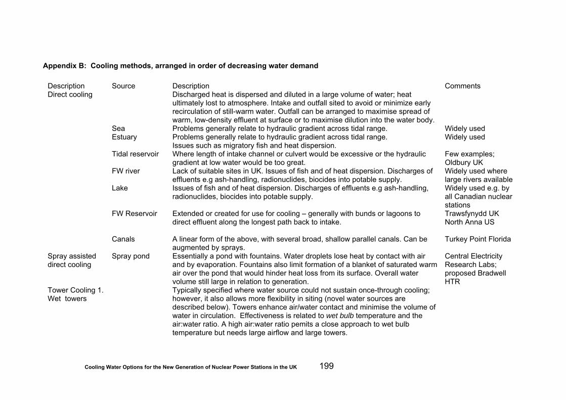
Cooling Water Options for the New Generation of Nuclear Power Stations in the UK 199
Appendix B: Cooling methods, arranged in order of decreasing water demand Description Source Description Comments Direct cooling Discharged heat is dispersed and diluted in a large volume of water; heat
ultimately lost to atmosphere. Intake and outfall sited to avoid or minimize early recirculation of still-warm water. Outfall can be arranged to maximise spread of warm, low-density effluent at surface or to maximise dilution into the water body.
Sea Problems generally relate to hydraulic gradient across tidal range. Widely used Estuary Problems generally relate to hydraulic gradient across tidal range.
Issues such as migratory fish and heat dispersion. Widely used
Tidal reservoir Where length of intake channel or culvert would be excessive or the hydraulic gradient at low water would be too great.
Few examples; Oldbury UK
FW river Lack of suitable sites in UK. Issues of fish and of heat dispersion. Discharges of effluents e.g ash-handling, radionuclides, biocides into potable supply.
Widely used where large rivers available
Lake Issues of fish and of heat dispersion. Discharges of effluents e.g ash-handling, radionuclides, biocides into potable supply.
Widely used e.g. by all Canadian nuclear stations
FW Reservoir Extended or created for use for cooling – generally with bunds or lagoons to direct effluent along the longest path back to intake.
Trawsfynydd UK North Anna US
Canals A linear form of the above, with several broad, shallow parallel canals. Can be augmented by sprays.
Turkey Point Florida
Spray assisted direct cooling
Spray pond Essentially a pond with fountains. Water droplets lose heat by contact with air and by evaporation. Fountains also limit formation of a blanket of saturated warm air over the pond that would hinder heat loss from its surface. Overall water volume still large in relation to generation.
Central Electricity Research Labs; proposed Bradwell HTR
Tower Cooling 1. Wet towers
Typically specified where water source could not sustain once-through cooling; however, it also allows more flexibility in siting (novel water sources are described below). Towers enhance air/water contact and minimise the volume of water in circulation. Effectiveness is related to wet bulb temperature and the air:water ratio. A high air:water ratio pemits a close approach to wet bulb temperature but needs large airflow and large towers.

Cooling Water Options for the New Generation of Nuclear Power Stations in the UK 200
1a. Natural draught towers
Spray towers Similar to a domestic shower. Water droplets fall freely inside an open-topped tower, entraining air that is carried down (co-current) and escapes through the louvered sides. Cooled water collects in the basin under the tower.
Small units only, less commonly used now.
Filled towers
Use fill (pack) beneath the water distribution system to prolong air/water contact time. Splash pack consists of tiers of horizontal timber or plastic laths onto which water showers, splashing, running over the lath as a thin film and dripping onto the lath below. This has largely been replaced by film-forming pack (film pack) down which water flows as a thin film. This yields lower recool temperatures but is more prone to fouling than the essentially self-cleaning splash pack. Towers come in all sizes but the large concrete hyperbolic ones probably are the most familiar. The “works” (water distribution and pack) occupy only a fraction of the height of the tower – the rest acts as a chimney drawing cold air through the pack (counter-current). The water collects in a pond at the base of the tower.
Large hyperbolic towers of this type are often the most evident part of a power station. Widely used
1b. Mechanical draught towers
These are lower than natural draught towers since they use fans (forced or induced draught) to push/pull air through the (usually) film-pack: these fans can be noisy. The pitch and/or speed of the fans can be varied and air distribution, in some towers, can be adjusted by doors. One disadvantage of these low towers is that plume formation occurs close to the ground and can result in fog or icing on nearby roads.
Commonly used for CCGTs. Built in banks to provide necessary capacity
Crossflow Air moves horizontally through the pack. The tower is usually lower than the counterflow pattern.
Counterflow Air moves vertically through the pack, against the flow of water. This gives more efficient heat transfer since the coolest water contacts the coolest air.
2. Hybrid wet and dry towers
These are mainly based on mechanical draught towers and have two sections. The upper dry section contains tubes, usually of the same material as condenser tubes, through which the cooling water flows. Here, heat is lost by conduction to air – sometimes referred to as the radiant section. The lower section is a standard wet tower. In some cases the dry section serves merely to heat the moist air from the wet section, thereby minimising low-level plume formation. In some situations it is possible to rely upon the dry section alone in cold weather.
3. Hybrid direct/indirect systems
Often called auxiliary tower systems. One or more towers are used to augment or completely replace the cooling capacity e.g. during periods of low river flow or when river temperature exceeds some preset value.
Barking UK
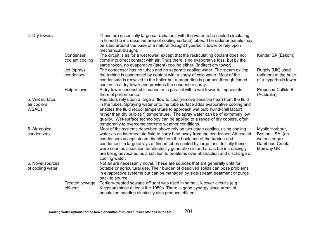
Cooling Water Options for the New Generation of Nuclear Power Stations in the UK 201
4. Dry towers These are essentially large car radiators, with the water to be cooled circulating in finned (to increase the area of cooling surface) tubes. The radiator panels may be sited around the base of a natural draught hyperbolic tower or rely upon mechanical draught.
Condenser coolant cooling
The circuit is as for a wet tower, except that the recirculating coolant does not come into direct contact with air. Thus there is no evaporative loss, but by the same token, no evaporative (latent) cooling either. (Indirect dry tower)
Kendal SA (Eskom)
Jet (spray) condenser
The condenser has no tubes and no separate cooling water. The steam exiting the turbine is condensed by contact with a spray of cold water. Most of the condensate is recycled to the boiler but a proportion is pumped through finned coolers in a dry tower and provides the condenser spray.
Rugely (UK) used radiators at the base of a hyperbolic tower
Helper tower A dry tower connected in series or in parallel with a wet tower to improve its thermal performance.
Proposed Callide B (Australia)
5. Wet surface air coolers WSACs
Radiators rely upon a large airflow to cool (remove sensible heat) from the fluid in the tubes. Spraying water onto the tube surface adds evaporative cooling and enables the fluid recool temperature to approach wet bulb (wind-chill factor) rather than dry bulb (air) temperature. The spray water can be of extremely low quality. Wet-surface technology can be applied to a range of dry coolers, often temporarily to overcome extreme weather conditions.
5. Air-cooled condensers
Most of the systems described above rely on two-stage cooling, using cooling water as an intermediate fluid to carry heat away from the condenser. Air-cooled condensers accept steam directly from the back-end of the turbine and condense it in large arrays of finned tubes cooled by large fans. Initially these were seen as a solution for electricity generation in arid areas but increasingly are being advocated as a solution to problems over abstraction and discharge of cooling water.
Mystic Harbour, Boston USA (on water’s edge). Damhead Creek, Medway UK
6. Novel sources of cooling water
Not all are necessarily novel. These are sources that are generally unfit for potable or agricultural use. Their burden of dissolved solids can pose problems in evaporative systems but can be managed by side-stream treatment or purge back to source.
Treated sewage effluent
Tertiary-treated sewage effluent was used in some UK tower circuits (e.g Kingston) since at least the 1950s. There is good synergy since areas of population needing electricity also produce effluent.
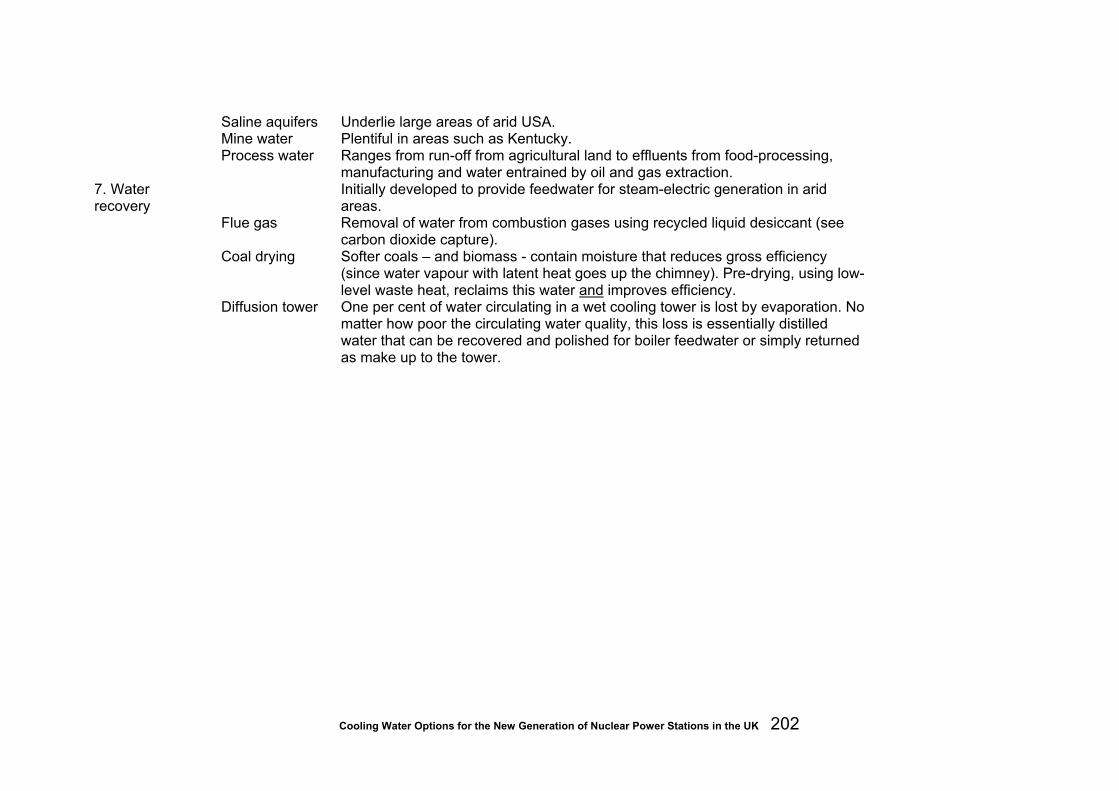
Cooling Water Options for the New Generation of Nuclear Power Stations in the UK 202
Saline aquifers Underlie large areas of arid USA. Mine water Plentiful in areas such as Kentucky. Process water Ranges from run-off from agricultural land to effluents from food-processing,
manufacturing and water entrained by oil and gas extraction.
7. Water recovery
Initially developed to provide feedwater for steam-electric generation in arid areas.
Flue gas Removal of water from combustion gases using recycled liquid desiccant (see carbon dioxide capture).
Coal drying Softer coals – and biomass - contain moisture that reduces gross efficiency (since water vapour with latent heat goes up the chimney). Pre-drying, using low-level waste heat, reclaims this water and improves efficiency.
Diffusion tower One per cent of water circulating in a wet cooling tower is lost by evaporation. No matter how poor the circulating water quality, this loss is essentially distilled water that can be recovered and polished for boiler feedwater or simply returned as make up to the tower.