
Cooling Towers 420.10-SED1 - Antaya Engineered Sales
24
COOLING TOWERS Form 420.10-SED1 (JUN 2007) SPECIFICATIONS - ENGINEERING DATA - DIMENSIONS Replaces: E200-210 SED (JUN 05)
Transcript of Cooling Towers 420.10-SED1 - Antaya Engineered Sales

COOLING TOWERS
Form 420.10-SED1 (JUN 2007) SPECIFICATIONS - ENGINEERING DATA - DIMENSIONS
Replaces: E200-210 SED (JUN 05)
420.10-SED1 (JUN 07)Page 2
COOLING TOWERSSPECIFICATIONS - ENGINEERING DATA - DIMENSIONS
ContentsIMC Line of Cooling Towers .....................................................................................................................................3Water Distribution System ........................................................................................................................................5Air Circulation System ..............................................................................................................................................5Belt Drive System .....................................................................................................................................................5Belt Drive System .....................................................................................................................................................6Fan Shaft Bearings ...................................................................................................................................................6Inlet Louver Design ..................................................................................................................................................6Inspection and Maintenance Accessibility ................................................................................................................7Gearbox Drive System .............................................................................................................................................7Heaters and Thermostats .........................................................................................................................................7SELECTION PROCEDURE .....................................................................................................................................8SELECTION FACTOR GRAPH ...............................................................................................................................9800 SERIES SINGLE CELL UNIT TOWER SELECTION ......................................................................................10800 SERIES DOUBLE CELL UNIT TOWER SELECTION ....................................................................................111212 UNIT TOWER SELECTION ..........................................................................................................................121218 UNIT TOWER SELECTION ..........................................................................................................................13Dimensions — IMC 806 .........................................................................................................................................14Platform Layout — IMC 806 ...................................................................................................................................14Dimensions and Platform Layout — IMC 809-1 .....................................................................................................15Dimensions and Platform Layout — IMC 809-2 .....................................................................................................15Dimensions and Platform Layout — IMC 812-1 .....................................................................................................16Dimensions and Platform Layout — IMC 812-2 .....................................................................................................16Dimensions and Platform Layout — IMC 1212-1 ...................................................................................................17Dimensions and Platform Layout — IMC 1212-2 ...................................................................................................17Dimensions and Platform Layout — IMC 1218-1 ...................................................................................................18Dimensions and Platform Layout — IMC 1218-2 ...................................................................................................18Dimensions and Platform Layout — IMC 1218-3 ...................................................................................................19Dimensions and Platform Layout — IMC 1218-4 ...................................................................................................19Specifications .........................................................................................................................................................20STANDARD ENGINEERING SPECIFICATIONS ...................................................................................................22OPTIONAL FEATURES AND EQUIPMENT ..........................................................................................................22

420.10-SED1 (JUN 07)Page 3
COOLING TOWERSSPECIFICATIONS - ENGINEERING DATA - DIMENSIONS
800 series
Our "twice the thickness" zinc also protects the holes and the sheet metal edges created by tower panel fabrication. Our metal doesn't deteriorate like the “painted holes and edges” inherent in the standard G235 “mill galvanized before fabrication” construction offered by others.
As has been graphically recorded by the American Galva-nizers Association, "twice the zinc" thickness directly corre-sponds to twice the corrosion protection, yielding dramatic increases in cooling tower longevity. Hot dip galvanized after fabrication tower panels are a prudent investment in the life of your cooling tower.
Reliable Year-Round Operation
The IMC series cooling tower is well suited for winter opera-tion. The induced draft counterflow design encases the wet fill section, isolating it from freezing winds. This inhibits ice formation in the fill and minimizes performance degrada-tion. It all but eliminates fill collapse. The basin’s internal bracing minimizes splashing that can cause inlet louver freezing.
Competitive crossflow designs have a tendency to form ice along the inlet louvers and fill during cold weather opera-tion. The buildup of ice reduces the unit’s thermal capacity and can cause costly damage to the fill and louvers.
Imeco's pressurized spray system allows customization of our towers for use in Free Cooling Systems. The spray pattern can be tailored for a specific climatic condition or is capable of a large variation in flow rates needed for sea-sonal changes. Please contact your local Imeco® represen-tative for your specific application.
IMC Line of Cooling TowersThe IMC series optimizes an induced draft counterflow design. Factory and field tests have proven that this is the most efficient design for cooling tower performance. Thus, the IMC’s enhanced performance yields lower operating costs; a tangible benefit for owners and operators.
The IMC series typically uses up to one third less plan area than a competitive crossflow tower of comparable capacity. Significant savings in structural support can be realized due to the related reduction (up to one third less) in cooling tower weight.
The IMC series is designed for air conditioning and indus-trial water cooling applications in a variety of climatic condi-tions. The IMC is a heavy-duty cooling tower. All of its major components, fans, inlets, motors, fill, nozzles, bearings, and gearboxes have been selected and built to ensure efficient and dependable service for years of trouble-free service.
Hot Dip Galvanizing
Imeco® stands alone in providing a hot dip galvanized after fabrication basin as standard on every cooling tower we build. We have "twice the thickness" zinc protection com-pared to competitors G235 “mill galvanized before fabrica-tion” offerings. Our hot dip galvanizing after fabrication process ensures the longevity and durability of your cooling tower installation.

420.10-SED1 (JUN 07)Page 4
COOLING TOWERSSPECIFICATIONS - ENGINEERING DATA - DIMENSIONS
Low Air Intake and Vertical Air Discharge
The low air intake and vertical discharge of the IMC series reduces the chances of air recirculation because the warm, humid discharge air is directed away from the unit’s inlet. The distance between inlet and discharge on an IMC is greater than for a comparable crossflow tower. This dis-tance further minimizes the potential for performance prob-lems associated with discharge air recirculation.
Efficient Drift Eliminators
The IMC series has an extremely efficient and cost effec-tive drift eliminator system. The standard, patented three-pass design removes entrained water droplets from the
discharge air and allows only 0.002% of the recirculating water to carry over. In areas where minimal water carryover is critical, Imeco® offers an optional system that has a drift rate of 0.001%.
The standard drift eliminator material is polyvinyl chloride (PVC). This is an inert plastic and is corrosion resistant to cooling tower environments and water treatments. For appli-cations in very hot climates such as a desert, the optional high-temperature (HPVC) eliminators can be used.
The drift eliminator sections are easily removable for inspection of the water distribution system and fill section.
Cooling Tower Fill
The IMC series uses a heavy-duty fill constructed from an inert plastic material. The fill is designed to produce multiple surfaces for water filming to occur and provide a highly turbulent mixing environment for the air and water. This enhances water cooling by maximizing latent and sensible heat transfer from the water to the air stream. The fill is constructed from crossfluted sheets bonded together. This construction produces a strong enough structure that, with care, can be used as a working platform.
The standard fill is constructed from PVC and will withstand continuous water temperatures of 135°F. An optional high-temperature fill is available for temperatures up to 150°F.
The fire-resistant qualities of the fill are excellent. In tests conducted in accordance with ASTM-E84-81a, its flame spread rating was 5. The flame spread rating scale ranges from 0 (noncombustible) to 100 (highly combustible).

420.10-SED1 (JUN 07)Page 5
COOLING TOWERSSPECIFICATIONS - ENGINEERING DATA - DIMENSIONS
Water Distribution SystemThe water distribution system is constructed from schedule 40 PVC pipe, rubber connection couplings, and polymer spray nozzles. The piping is easily removable for cleaning. The IMC 1200 series spray header has a removable cover plate opposite the inlet connection that allows the main distribution header to be thoroughly cleaned. The standard spray nozzles have a minimum opening width of 3/8 inch, for maximum resistance to clogging.
The nozzle system provides an even water pattern over the fill, ensuring optimal thermal performance. The pat-tern is stable over an extremely wide range of flow rates. This stable pattern allows IMC series cooling towers to be customized for Free Cooling or for customer specific climatic conditions. This system is ideal for cold weather applications.
Air Circulation SystemCorrosion resistant aluminum axial fans are used to circu-late air through the IMC series cooling towers. The 1200 series fans are powered by specially built motors that are VFD (variable frequency drive) ready and have a unique five-year warranty. The IMC standard fan drive features optimized banded belts and custom built bearings. An optional gearbox drive is also available.
Belt Drive SystemAluminum Alloy SheavesThe drive system sheaves that are located inside the cool-ing tower are constructed of a corrosion resistant aluminum alloy. The aluminum sheave is superior to steel or cast iron due to its light weight and corrosion resistance. It is also superior to competitive nylon sheaves which absorb water and tend to shrink and crack over time in cooling tower applications.
Power BandsThe power band belt is a banded multigroove belt con-structed from premium quality rubber compounds using tough synthetic cords. This is the most efficient type of belt for cooling tower applications. For extended life, the belt is sized as a minimum, for 150% of the motor nameplate horsepower.

420.10-SED1 (JUN 07)Page 6
COOLING TOWERSSPECIFICATIONS - ENGINEERING DATA - DIMENSIONS
Belt Drive SystemFan MotorsIMC 800 SeriesThe fan motor is VFD ready and totally enclosed fan cooled (TEFC) with a service factor of 1.15 and suitable for cooling tower use. The motor is mounted outside of the tower on a steel frame that is hot dip galvanized after fabrication for maximum corrosion protection. Motor inspection and belt adjustment are easily accomplished from the outside. A removable hood shields the motor and sheave from the weather.
Multispeed motors and premium efficiency inverter-duty motors are available to meet your capacity control needs.
IMC 1200 SeriesThe standard fan motor is totally enclosed with a service factor of 1.15 built exclusively to Imeco’s specifications for use in our cooling towers. The motor is VFD ready.
The motor is environmentally sealed to prevent contami-nants and moisture from entering the casing. Imeco’s spe-cially designed motor drains and vents ensure that moisture will be purged from the motor to extend useful life.
Imeco® motors are guaranteed for five years mechanically and electrically in non-VFD applications. When used with a VFD, the motor is guaranteed for three years electrically and five years mechanically.
Optional multispeed motors suitable for cooling tower appli-cations are offered as an alternative means to meet your capacity control needs.
Fan Shaft BearingsIMC 800 SeriesThe bearing races are specially treated and additional seals are added for cooling tower application. This provides a long, trouble-free life.
Lubrication lines are extended to the casing for easy main-tenance from outside the tower.
IMC 1200 SeriesThe fan shaft bearings are flange-mounted, self-aligning roller bearings with a five-year warranty. The bearing is specially built to an Imeco® specification for use inside a cooling tower. The flange mount is superior in design to the standard pillow block for the high thrust loads that occur with the use of large diameter axial fans. This bearing has a minimum L10 of 133,500 hours, 78% greater than the competition.
Lubrication lines are extended through the casing for easy maintenance from outside the tower.
Imeco® offers a five-year warranty on its 1200 series fan shaft bearings.
Inlet Louver DesignThe air inlet louvers are constructed of corrosion-free PVC. They have a two-pass design that eliminates splashout and inhibits algae growth inside the tower basin. This design also has a low pressure drop, minimizing fan energy con-sumption.

420.10-SED1 (JUN 07)Page 7
COOLING TOWERSSPECIFICATIONS - ENGINEERING DATA - DIMENSIONS
Gearbox Drive System (Optional)A gearbox designed for use in cooling towers is an option on all models. The gearbox is coupled to a motor; motor has a 1.15 service factor. An oil level sight glass is provided on the outside of the unit for easy inspection.
Heaters and Thermostats (Optional)Electric immersion heaters are available factory installed in the basin of the tower. They are sized to maintain a +42°F pan water temperature with the fans off at several outdoor ambient temperatures and a 45 mph wind. They are fur-nished with a NEMA 4 thermostat to cycle the heater on when required. A NEMA 4 cutoff switch is included to pre-vent the control from energizing the heater elements unless they are completely submerged.
The heater power contactors and electric wiring are not included as standard. (See chart below.)
Inspection andMaintenance AccessibilityThe basin is open and accessible from ground level by simply removing a section of inlet lou-ver. There is a depressed section of the basin designed to accumulate solid impurities. These impurities are easily flushed out through the drain with a hose.
A large access door is provided in the fan section for access to the drift eliminators, fill, spray sys-tem, and fan drive components. Optional handrails on the top of the unit can be provided upon request.
IMC kW MODEL 0 -10 -20 806 4.5 6 6 809 6 7.5 9 812 7.5 9 12 1212 2 @ 6.0 2 @ 6.0 2 @ 7.5 1218 2 @ 7.5 2 @ 9.0 2 @ 12
Gearbox
Heaters and Thermostats
420.10-SED1 (JUN 07)Page 8
COOLING TOWERSENGINEERING DATA
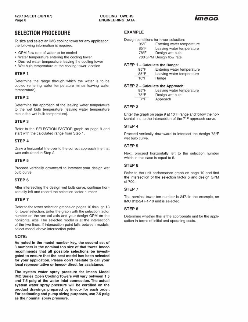
SELECTION PROCEDURETo size and select an IMC cooling tower for any application, the following information is required:
• GPM flow rate of water to be cooled• Water temperature entering the cooling tower• Desired water temperature leaving the cooling tower• Wet bulb temperature at the cooling tower location
STEP 1
Determine the range through which the water is to be cooled (entering water temperature minus leaving water temperature).
STEP 2
Determine the approach of the leaving water temperature to the wet bulb temperature (leaving water temperature minus the wet bulb temperature).
STEP 3
Refer to the SELECTION FACTOR graph on page 9 and start with the calculated range from Step 1.
STEP 4
Draw a horizontal line over to the correct approach line that was calculated in Step 2.
STEP 5
Proceed vertically downward to intersect your design wet bulb curve.
STEP 6
After intersecting the design wet bulb curve, continue hori-zontally left and record the selection factor number.
STEP 7
Refer to the tower selection graphs on pages 10 through 13 for tower selection. Enter the graph with the selection factor number on the vertical axis and your design GPM on the horizontal axis. The selected model is at the intersection of the two lines. If intersection point falls between models, select model above intersection point.
NOTE:As noted in the model number key, the second set of 3 numbers is the nominal ton size of that tower. Imeco recommends that all possible selections be investi-gated to ensure that the best model has been selected for your application. Please don’t hesitate to call your local representative or Imeco® direct for assistance.
The system water spray pressure for Imeco Model IMC Series Open Cooling Towers will vary between 1.5 and 7.5 psig at the water inlet connection. The actual system water spray pressure will be certified on the product drawings prepared by Imeco® for each order. For estimating and pump sizing purposes, use 7.5 psig as the nominal spray pressure.
EXAMPLE
Design conditions for tower selection: 95°F Entering water temperature 85°F Leaving water temperature 78°F Design wet bulb 700 GPM Design flow rate
STEP 1 – Calculate the Range: 95°F Entering water temperature - 85°F Leaving water temperature 10°F Range
STEP 2 – Calculate the Approach: 85°F Leaving water temperature - 78°F Design wet bulb 7°F Approach
STEP 3
Enter the graph on page 9 at 10°F range and follow the hor-izontal line to the intersection of the 7°F approach curve.
STEP 4
Proceed vertically downward to intersect the design 78°F wet bulb curve.
STEP 5
Next, proceed horizontally left to the selection number which in this case is equal to 5.
STEP 6
Refer to the unit performance graph on page 10 and find the intersection of the selection factor 5 and design GPM of 700.
STEP 7
The nominal tower ton number is 247. In the example, an IMC 812-247-1-10 unit is selected.
STEP 8
Determine whether this is the appropriate unit for the appli-cation in terms of initial and operating costs.

420.10-SED1 (JUN 07)Page 9
COOLING TOWERSENGINEERING DATA
SELECTION FACTOR GRAPH

420.10-SED1 (JUN 07)Page 10
COOLING TOWERSENGINEERING DATA
Enter the graph with the selection factor number on the vertical axis and your design GPM on the horizontal axis.
The selected model is at the intersection of the two lines.
If intersection point falls between models, select model above intersection point.
800 SERIES SINGLE CELL UNIT TOWER SELECTION

420.10-SED1 (JUN 07)Page 11
COOLING TOWERSENGINEERING DATA
Enter the graph with the selection factor number on the vertical axis and your design GPM on the horizontal axis.
The selected model is at the intersection of the two lines.
If intersection point falls between models, select model above intersection point.
800 SERIES DOUBLE CELL UNIT TOWER SELECTION

420.10-SED1 (JUN 07)Page 12
COOLING TOWERSENGINEERING DATA
Enter the graph with the selection factor number on the vertical axis and your design GPM on the horizontal axis.
The selected model is at the intersection of the two lines.
If intersection point falls between models, select model above intersection point.
1212 UNIT TOWER SELECTION

420.10-SED1 (JUN 07)Page 13
COOLING TOWERSENGINEERING DATA
Enter the graph with the selection factor number on the vertical axis and your design GPM on the horizontal axis.
The selected model is at the intersection of the two lines.
If intersection point falls between models, select model above intersection point.
1218 UNIT TOWER SELECTION

420.10-SED1 (JUN 07)Page 14
COOLING TOWERSDIMENSIONS
Do not use for construction purposes - detailed drawings available on request.
NOTE: This diagram applies to all of the following Platform Layouts.
Dimensions — IMC 806
Platform Layout — IMC 806

420.10-SED1 (JUN 07)Page 15
COOLING TOWERSDIMENSIONS
Do not use for construction purposes - detailed drawings available on request.
Dimensions and Platform Layout — IMC 809-1
Dimensions and Platform Layout — IMC 809-2

420.10-SED1 (JUN 07)Page 16
COOLING TOWERSDIMENSIONS
Do not use for construction purposes - detailed drawings available on request.
Dimensions and Platform Layout — IMC 812-1
Dimensions and Platform Layout — IMC 812-2

420.10-SED1 (JUN 07)Page 17
COOLING TOWERSDIMENSIONS
Do not use for construction purposes - detailed drawings available on request.
Dimensions and Platform Layout — IMC 1212-1
Dimensions and Platform Layout — IMC 1212-2

420.10-SED1 (JUN 07)Page 18
COOLING TOWERSDIMENSIONS
Do not use for construction purposes - detailed drawings available on request.
Dimensions and Platform Layout — IMC 1218-1
Dimensions and Platform Layout — IMC 1218-2

420.10-SED1 (JUN 07)Page 19
COOLING TOWERSDIMENSIONS
Do not use for construction purposes - detailed drawings available on request.
Dimensions and Platform Layout — IMC 1218-3
Dimensions and Platform Layout — IMC 1218-4

420.10-SED1 (JUN 07)Page 20
COOLING TOWERSSPECIFICATIONS
IMC 809-310-2-10 (2) 10 HP 88,200 131.500 98.250 220.750 2' (2)8" FLG (2) 8" PE (2) 1.250" MPT (2) 2" FPT (2) 3" MPT 7,080 13,920 2,370
IMC 809-300-2-7.5 (2) 7.5 HP 78,350 137.500 98.250 220.750 2.5' (2) 8" FLG (2) 8" PE (2) 1.250" MPT (2) 2" FPT (2) 3" MPT 7,340 14,200 2,500
IMC 809-340-2-10 (2) 10 HP 86,800 137.500 98.250 220.750 2.5' (2) 8" FLG (2) 8" PE (2) 1.250" MPT (2) 2" FPT (2) 3" MPT 7,340 14,200 2,500
IMC 809-380-2-15 (2) 15 HP 99,200 137.500 98.250 220.750 2.5' (2) 8" FLG (2) 8" PE (2) 1.250" MPT (2) 2" FPT (2) 3" MPT 7,340 14,200 2,500
IMC 809-360-2-10 (2) 10 HP 86,150 143.500 98.250 220.750 3' (2) 8" FLG (2) 8" PE (2) 1.250" MPT (2) 2" FPT (2) 3" MPT 7,600 14,460 2,630
IMC 809-447-2-20 (2) 20 HP 107,700 143.500 98.250 220.750 3' (2) 8" FLG (2) 8" PE (2) 1.250" MPT (2) 2" FPT (2) 3" MPT 7,600 14,460 2,630
IMC 809-467-2-20 (2) 20 HP 101,650 155.500 98.250 220.750 4' (2) 8" FLG (2) 8" PE (2) 1.250" MPT (2) 2" FPT (2) 3" MPT 8,120 14,980 2,890
Model # Motor HP Total Height Width Length Fill Water Water Makeup Drain Overflow Weight (Ib) cfm (H) Height In Out Shipping Operating Heaviest
IMC 812-205-1-15 (1) 15 HP 63,900 140.500 98.250 142.750 2' 8" FLG 8" PE 1.250" MPT 2" FPT 3" MPT 4,200 8,680 2,810
IMC 812-200-1-10 (1) 10 HP 53,900 146.500 98.250 142.750 2.5' 8" FLG 8" PE 1.250" MPT 2" FPT 3" MPT 4,370 8,850 2,980
IMC 812-245-1-20 (1) 20 HP 68,450 146.500 98.250 142.750 2.5' 8" FLG 8" PE 1.250" MPT 2" FPT 3" MPT 4,370 8,850 2,980
IMC 812-246-1-15 (1) 15 HP 61,000 152.500 98.250 142.750 3' 8" FLG 8" PE 1.250" MPT 2" FPT 3" MPT 4,540 9,020 3,150
IMC 812-260-1-20 (1) 20 HP 67,500 152.500 98.250 142.750 3' 8" FLG 8" PE 1.250" MPT 2" FPT 3" MPT 4,540 9,020 3,150
IMC 812-247-1-10 (1) 10 HP 53,650 158.500 98.250 142.750 3.5' 8" FLG 8" PE 1.250" MPT 2" FPT 3" MPT 4,710 9,190 3,320
IMC 812-273-1-15 (1) 15 HP 61,000 158.500 98.250 142.750 3.5' 8" FLG 8" PE 1.250" MPT 2" FPT 3" MPT 4,710 9,190 3,320
IMC 812-280-1-15 (1) 15 HP 59,250 164.500 98.250 142.750 4' 8" FLG 8" PE 1.250" MPT 2" FPT 3" MPT 4,880 9,360 3,490
IMC 812-297-1-20 (1) 20 HP 64,800 164.500 98.250 142.750 4' 8" FLG 8" PE 1.250" MPT 2" FPT 3" MPT 4,880 9,360 3,490
IMC 812-317-1-25 (1) 25 HP 69,700 164.500 98.250 142.750 4' 8" FLG 8" PE 1.250" MPT 2" FPT 3" MPT 4,880 9,360 3,490
Model # Motor HP Total Height Width Length Fill Water Water Makeup Drain Overflow Weight (Ib) cfm (H) Height In Out Shipping Operating Heaviest
IMC 806-080-1-3 (1) 3 HP 24,150 125.500 98.250 71.375 2' 6" FLG 8" PE 1.250" MPT 2" FPT 3" MPT 2,630 4,770 1,770
IMC 806-100-1-5 (1) 5 HP 28,500 125.500 98.250 71.375 2' 6" FLG 8" PE 1.250" MPT 2" FPT 3" MPT 2,630 4,770 1,770
IMC 806-110-1-7.5 (1) 7.5 HP 32,600 125.500 98.250 71.375 2' 6" FLG 8" PE 1.250" MPT 2" FPT 3" MPT 2,630 4,770 1,770
IMC 806-112-1-5 (1) 5 HP 26,350 131.500 98.250 71.375 2.5' 6" FLG 8" PE 1.250" MPT 2" FPT 3" MPT 2,730 4,870 1,870
IMC 806-125-1-10 (1) 10 HP 34,350 131.500 98.250 71.375 2.5' 6" FLG 8" PE 1.250" MPT 2" FPT 3" MPT 2,730 4,870 1,870
IMC 806-115-1-5 (1) 5 HP 26,350 137.500 98.250 71.375 3' 6" FLG 8" PE 1.250" MPT 2" FPT 3" MPT 2,830 4,970 1,970
IMC 806-130-1-7.5 (1) 7.5 HP 30,100 137.500 98.250 71.375 3' 6" FLG 8" PE 1.250" MPT 2" FPT 3" MPT 2,830 4,970 1,970
IMC 806-136-1-7.5 (1) 7.5 HP 28,000 149.500 98.250 71.375 4' 6" FLG 8" PE 1.250" MPT 2" FPT 3" MPT 3,030 5,170 2,170
IMC 806-145-1-10 (1) 10 HP 30,750 149.500 98.250 71.375 4' 6" FLG 8" PE 1.250" MPT 2" FPT 3" MPT 3,030 5,170 2,170
IMC 806-155-1-15 (1) 15 HP 34,850 149.500 98.250 71.375 4' 6" FLG 8" PE 1.250" MPT 2" FPT 3" MPT 3,030 5,170 2,170
IMC 806-1
IMC 812-1
Model # Motor HP Total Height Width Length Fill Water Water Makeup Drain Overflow Weight (Ib) cfm (H) Height In Out Shipping Operating Heaviest
IMC 809-140-1-7.5 (1) 7.5 HP 40,550 125.500 98.250 110.375 2' 8" FLG 8" PE 1.250" MPT 2" FPT 3" MPT 3,540 6,960 2,370
IMC 809-156-1-10 (1) 10 HP 44,550 125.500 98.250 110.375 2' 8" FLG 8" PE 1.250" MPT 2" FPT 3" MPT 3,540 6,960 2,370
IMC 809-170-1-10 (1) 10 HP 43,850 131.500 98.250 110.375 2.5' 8" FLG 8" PE 1.250" MPT 2" FPT 3" MPT 3,670 7,100 2,500
IMC 809-190-1-15 (1) 15 HP 50,100 131.500 98.250 110.375 2.5' 8" FLG 8" PE 1.250" MPT 2" FPT 3" MPT 3,670 7,100 2,500
IMC 809-180-1-10 (1) 10 HP 43,500 137.500 98.250 110.375 3' 8" FLG 8" PE 1.250" MPT 2" FPT 3" MPT 3,800 7,230 2,630
IMC 809-206-1-15 (1) 15 HP 49,650 137.500 98.250 110.375 3' 8" FLG 8" PE 1.250" MPT 2" FPT 3" MPT 3,800 7,230 2,630
IMC 809-217-1-15 (1) 15 HP 47,150 149.500 98.250 110.375 4' 8" FLG 8" PE 1.250" MPT 2" FPT 3" MPT 4,060 7,490 2,890
IMC 809-234-1-20 (1) 20 HP 51,350 149.500 98.250 110.375 4' 8" FLG 8" PE 1.250" MPT 2" FPT 3" MPT 4,060 7,490 2,890
IMC 809-1
IMC 809-2
IMC 812-2IMC 812-440-2-20 (2) 20 HP 140,900 146.5 98.25 285.5 2’ (2) 8” FLG (2) 8” PE (2) 1.250” MPT (2) 2” FPT (2) 3” MPT 8,400 17,360 2,810
IMC 812-405-2-10 (2) 10 HP 107,250 152.5 98.25 285.5 2.5’ (2) 8” FLG (2) 8” PE (2) 1.250” MPT (2) 2” FPT (2) 3” MPT 8,740 17,700 2,980
IMC 812-430-2-10 (2) 10 HP 106,300 158.5 98.25 285.5 3’ (2) 8” FLG (2) 8” PE (2) 1.250” MPT (2) 2” FPT (2) 3” MPT 9,080 18,040 3,150
IMC 812-520-2-20 (2) 20 HP 134,350 158.5 98.25 285.5 3’ (2) 8” FLG (2) 8” PE (2) 1.250” MPT (2) 2” FPT (2) 3” MPT 9,080 18,040 3,150
IMC 812-590-2-20 (2) 20 HP 132,750 164.5 98.25 285.5 3.5’ (2) 8” FLG (2) 8” PE (2) 1.250” MPT (2) 2” FPT (2) 3” MPT 9,420 18,380 3,320
IMC 812-600-2-20 (2) 20 HP 128,950 170.5 98.25 285.5 4’ (2) 8” FLG (2) 8” PE (2) 1.250” MPT (2) 2” FPT (2) 3” MPT 9,760 18,720 3,490
IMC 812-632-2-25 (2) 25 HP 138,700 170.5 98.25 285.5 4’ (2) 8” FLG (2) 8” PE (2) 1.250” MPT (2) 2” FPT (2) 3” MPT 9,760 18,720 3,490
Specifications

420.10-SED1 (JUN 07)Page 21
COOLING TOWERSSPECIFICATIONS
IMC 1218-1750-4-25 (4) 25 HP 523,050 190.500 142.000 880.000 2' (4) 10" FLG (4) 10" PE (4) 2" MPT (4) 3" MPT (4) 3" MPT 33,040 85,660 5,110
IMC 1218-1955-4-20 (4) 20 HP 466,500 202.500 142.000 880.000 3' (4) 10" FLG (4) 10" PE (4) 2" MPT (4) 3" MPT (4) 3" MPT 36,520 97,280 5,575
IMC 1218-2100-4-25 (4) 25 HP 501,150 202.500 142.000 880.000 3' (4) 10" FLG (4) 10" PE (4) 2" MPT (4) 3" MPT (4) 3" MPT 36,520 97,280 5,575
IMC 1218-2215-4-30 (4) 30 HP 532,300 202.500 142.000 880.000 3' (4) 10" FLG (4) 10" PE (4) 2" MPT (4) 3" MPT (4) 3" MPT 36,520 97,280 5,575
IMC 1218-2410-4-40 (4) 40 HP 583,900 202.500 142.000 880.000 3' (4) 10" FLG (4) 10" PE (4) 2" MPT (4) 3" MPT (4) 3" MPT 36,520 97,280 5,575
IMC 1218-2587-4-40 (4) 40 HP 556,900 214.500 142.000 880.000 4' (4) 10" FLG (4) 10" PE (4) 2" MPT (4) 3" MPT (4) 3" MPT 40,000 108,900 6,040
IMC 1218-2750-4-50 (4) 50 HP 598,100 214.500 142.000 880.000 4' (4) 10" FLG (4) 10" PE (4) 2" MPT (4) 3" MPT (4) 3" MPT 40,000 108,900 6,040
IMC 1218-840-2-20 (2) 20 HP 243,450 190.500 142.000 438.000 2' (2) 10" FLG (2) 10" PE (2) 2" MPT (2) 3" MPT (2) 3" MPT 16,520 42,830 5,110
IMC 1218-910-2-25 (2) 25 HP 265,500 190.500 142.000 438.000 2' (2) 10" FLG (2) 10" PE (2) 2" MPT (2) 3" MPT (2) 3" MPT 16,520 42,830 5,110
IMC 1218-960-2-30 (2) 30 HP 281,900 190.500 142.000 438.000 2' (2) 10" FLG (2) 10" PE (2) 2" MPT (2) 3" MPT (2) 3" MPT 16,520 42,830 5,110
IMC 1218-1085-2-25 (2) 25 HP 254,400 202.500 142.000 438.000 3' (2) 10" FLG (2) 10" PE (2) 2" MPT (2) 3" MPT (2) 3" MPT 18,260 48,640 5,575
IMC 1218-1150-2-30 (2) 30 HP 270,200 202.500 142.000 438.000 3' (2) 10" FLG (2) 10" PE (2) 2" MPT (2) 3" MPT (2) 3" MPT 18,260 48,640 5,575
IMC 1218-1255-2-40 (2) 40 HP 296,400 202.500 142.000 438.000 3' (2) 10" FLG (2) 10" PE (2) 2" MPT (2) 3" MPT (2) 3" MPT 18,260 48,640 5,575
IMC 1218-1250-2-30 (2) 30 HP 257,600 214.500 142.000 438.000 4' (2) 10" FLG (2) 10" PE (2) 2" MPT (2) 3" MPT (2) 3" MPT 20,000 54,450 6,040
IMC 1218-1342-2-40 (2) 40 HP 282,700 214.500 142.000 438.000 4' (2) 10" FLG (2) 10" PE (2) 2" MPT (2) 3" MPT (2) 3" MPT 20,000 54,450 6,040
IMC 1218-1427-2-50 (2) 50 HP 303,600 214.500 142.000 438.000 4' (2) 10" FLG (2) 10" PE (2) 2" MPT (2) 3" MPT (2) 3" MPT 20,000 54,450 6,040
IMC 1212-580-2-20 (2) 20 HP 188,250 190.500 142.000 288.000 2' (2) 8" FLG (2) 8" PE (2) 2" MPT (2) 3" MPT (2) 3" MPT 10,680 29,180 3,290
IMC 1212-610-2-25 (2) 25 HP 204,000 190.500 142.000 288.000 2' (2) 8" FLG (2) 8" PE (2) 2" MPT (2) 3" MPT (2) 3" MPT 10,680 29,180 3,290
IMC 1212-685-2-20 (2) 20 HP 180,600 202.500 142.000 288.000 3' (2) 8" FLG (2) 8" PE (2) 2" MPT (2) 3" MPT (2) 3" MPT 11,480 32,380 3,690
IMC 1212-720-2-25 (2) 25 HP 194,400 202.500 142.000 288.000 3' (2) 8" FLG (2) 8" PE (2) 2" MPT (2) 3" MPT (2) 3" MPT 11,480 32,380 3,690
IMC 1212-760-2-30 (2) 30 HP 205,350 202.500 142.000 288.000 3' (2) 8" FLG (2) 8" PE (2) 2" MPT (2) 3" MPT (2) 3" MPT 11,480 32,380 3,690
IMC 1212-870-2-25 (2) 25 HP 183,800 214.500 142.000 288.000 4' (2) 8" FLG (2) 8" PE (2) 2" MPT (2) 3" MPT (2) 3" MPT 12,280 33,180 4,090
IMC 1212-927-2-30 (2) 30 HP 194,500 214.500 142.000 288.000 4' (2) 8" FLG (2) 8" PE (2) 2" MPT (2) 3" MPT (2) 3" MPT 12,280 33,180 4,090
IMC 1218-1370-3-25 (3) 25 HP 394,250 190.500 142.000 659.000 2’ (3) 10” FLG (3) 10” PE (3) 2” MPT (3) 3” MPT (3) 3” MPT 24,780 64,245 5,110
IMC 1218-1445-3-30 (3) 30 HP 418,600 190.500 142.000 659.000 2’ (3) 10” FLG (3) 10” PE (3) 2” MPT (3) 3” MPT (3) 3” MPT 24,780 64,245 5,110
IMC 1218-1730-3-30 (3) 30 HP 401,250 202.500 142.000 659.000 3’ (3) 10” FLG (3) 10” PE (3) 2” MPT (3) 3” MPT (3) 3” MPT 27,390 72,960 5,575
IMC 1218-1885-3-40 (3) 40 HP 440,150 202.500 142.000 659.000 3’ (3) 10” FLG (3) 10” PE (3) 2” MPT (3) 3” MPT (3) 3” MPT 27,390 72,960 5,575
IMC 1218-2000-3-40 (3) 40 HP 419,800 214.500 142.000 659.000 4’ (3) 10” FLG (3) 10” PE (3) 2” MPT (3) 3” MPT (3) 3” MPT 30,000 81,675 6,040
IMC 1218-2127-3-50 (3) 50 HP 450,850 214.500 142.000 659.000 4’ (3) 10” FLG (3) 10” PE (3) 2” MPT (3) 3” MPT (3) 3” MPT 30,000 81,675 6,040
Model # Motor HP Total Height Width Length Fill Water Water Makeup Drain Overflow Weight (Ib) cfm (H) Height In Out Shipping Operating Heaviest
IMC 1218-460-1-25 (1) 25 HP 132,750 178.500 142.000 217.000 2' 10" FLG 10" PE 2" MPT 3" MPT 3" MPT 8,260 21,415 5,110
IMC 1218-485-1-30 (1) 30 HP 140,950 178.500 142.000 217.000 2' 10" FLG 10" PE 2" MPT 3" MPT 3" MPT 8,260 21,415 5,110
IMC 1218-545-1-25 (1) 25 HP 127,200 190.500 142.000 217.000 3' 10" FLG 10" PE 2" MPT 3" MPT 3" MPT 9,130 24,320 5,575
IMC 1218-580-1-30 (1) 30 HP 135,100 190.500 142.000 217.000 3' 10" FLG 10" PE 2" MPT 3" MPT 3" MPT 9,130 24,320 5,575
IMC 1218-630-1-40 (1) 40 HP 148,200 190.500 142.000 217.000 3' 10" FLG 10" PE 2" MPT 3" MPT 3" MPT 9,130 24,320 5,575
IMC 1218-627-1-30 (1) 30 HP 128,800 202.500 142.000 217.000 4' 10" FLG 10" PE 2" MPT 3" MPT 3" MPT 10,000 27,225 6,040
IMC 1218-677-1-40 (1) 40 HP 141,350 202.500 142.000 217.000 4' 10" FLG 10" PE 2" MPT 3" MPT 3" MPT 10,000 27,225 6,040
IMC 1218-717-1-50 (1) 50 HP 151,800 202.500 142.000 217.000 4' 10" FLG 10" PE 2" MPT 3" MPT 3" MPT 10,000 27,225 6,040
Model # Motor HP Total Height Width Length Fill Water Water Makeup Drain Overflow Weight (Ib) cfm (H) Height In Out Shipping Operating Heaviest
IMC 1212-265-1-15 (1) 15 HP 85,300 178.500 142.000 142.000 2' 8" FLG 8" PE 2" MPT 3" MPT 3" MPT 5,340 14,590 3,290
IMC 1212-290-1-20 (1) 20 HP 94,600 178.500 142.000 142.000 2' 8" FLG 8" PE 2" MPT 3" MPT 3" MPT 5,340 14,590 3,290
IMC 1212-305-1-25 (1) 25 HP 102,500 178.500 142.000 142.000 2' 8" FLG 8" PE 2" MPT 3" MPT 3" MPT 5,340 14,590 3,290
IMC 1212-325-1-30 (1) 30 HP 108,850 178.500 142.000 142.000 2' 8" FLG 8" PE 2" MPT 3" MPT 3" MPT 5,340 14,590 3,290
IMC 1212-345-1-20 (1) 20 HP 90,750 190.500 142.000 142.000 3' 8" FLG 8" PE 2" MPT 3" MPT 3" MPT 5,740 16,190 3,690
IMC 1212-360-1-25 (1) 25 HP 97,700 190.500 142.000 142.000 3' 8" FLG 8" PE 2" MPT 3" MPT 3" MPT 5,740 16,190 3,690
IMC 1212-438-1-25 (1) 25 HP 92,350 202.500 142.000 142.000 4' 8" FLG 8" PE 2" MPT 3" MPT 3" MPT 6,140 16,590 4,090
IMC 1212-457-1-30 (1) 30 HP 97,750 202.500 142.000 142.000 4' 8" FLG 8" PE 2" MPT 3" MPT 3" MPT 6,140 16,590 4,090
IMC 1212-1
IMC 1218-1
IMC 1212-2
IMC 1218-2
IMC 1218-3
IMC 1218-4

420.10-SED1 (JUN 07)Page 22
COOLING TOWERSSPECIFICATIONS - ENGINEERING DATA - DIMENSIONS
STANDARD ENGINEERING SPECIFICATIONSIMC INDUCED DRAFT COOLING TOWERUtilizes an induced draft counterflow design, the most efficient design in cooling towers. All of its major components, wet-deck fill, inlet louvers, axial fans and motors have been selected and designed to ensure energy efficient operation.
CAPACITYThe IMC induced draft cooling tower(s) shall have a capacity to cool not less than _______ GPM to _______ °F at _______ °F wet bulb tempera-ture.
WATER BASIN SECTIONThe water basin shall have a sloped bottom design to facilitate cleaning. Accumulated dirt is washed down during normal operation and is flushed out to the drain with a hose through any of the removable inlet louver assemblies. The water basin shall be constructed of steel panels hot dip galvanized after fabrication. The water basin section is open and easily accessible by loosening two fasteners on each inlet louver assembly. Air inlet louvers will be constructed of corrosion resistant polyvinyl chloride (PVC) with a two-pass design.
FAN SECTIONFan shall be propeller type, incorporating heavy-duty, adjustable-pitch aluminum blades. Fans shall be driven with a V-belt system designed for cooling tower service and are constructed of neoprene with polyester cords. The belt is sized for 150% of the motor nameplate horsepower. The fan sheave is constructed of heavy-duty, corrosion-resistant cast aluminum alloy. The fan shall be mounted on a steel shaft supported by heavy-duty, self-aligning bearings with a minimum L10 life of 80,000 hours. Fan section housing is constructed of G-210 mill galvanized steel.
FAN MOTORFan shall be driven by _______ hp, 1800 rpm totally enclosed air over, ball bearing NEMA “T” frame motor with 1.15 service factor. Motor shall be suitable for cooling tower duty on ______ volt, _______ phase, _______ hertz electrical service.
COOLING TOWER FILLFill shall be a film-type constructed of polyvinyl chloride (PVC) formulated to withstand water temperatures of 130° F. Fill shall be suspended from hot dip galvanized after fabrication structural supports that are supported from the upper tower structure and will be elevated above the floor of the water basin to facilitate cleaning. Fill section housing is G-210 mill galvanized steel. DRIFT ELIMINATORSConstructed of corrosion resistant polyvinyl chloride (PVC). Eliminators will limit the drift rate to less than .002% of the recirculating water rate.
WATER DISTRIBUTION SYSTEMThe water distribution system tree branches are constructed of corrosion resistant schedule 40 PVC pipe and are fitted with corrosion resistant, nonclogging ABS spray nozzles. The ABS spray nozzles create an overlap-ping spray pattern and optimally distribute the system water over the wet-deck fill.
OPTIONAL FEATURES AND EQUIPMENTREMOTE SUMP OPERATIONUsing a 10" plain end bottom-outlet connection will eliminate the need for sump strainers, antivortex hood, water makeup connection and water makeup valve. Please contact the factory for exact location of remote sump outlet connection.
STAINLESS STEEL CONSTRUCTIONAll components of unit with the exception of the fan guard, fan shaft, bear-ings, bushings, sheaves and water makeup valve are manufactured of heavy-gauge stainless steel sheeting. Fan guard is furnished hot dip galva-
nized after fabrication. All surfaces of fan shaft, bearings, bushings and motor sheave are provided with a heavy coat of zinc-rich paint for corrosion protection.
STAINLESS STEEL BASINAll components of “basin” only are constructed of heavy-gauge stainless steel. Strainers and antivortex sump hood are included.
FLANGED OUTLETFactory installed “welded” 150#, forged steel raised face, slip-on pipe flanges on outlet connections of unit are available.
ELECTRIC WATER MAKEUPThe standard mechanical water makeup valve is a 120-1-60 electric water makeup solenoid valve. Also included is a 120-1-60 electric water level sensor mounted in an isolation chamber. All components are factory mounted (wiring not included).
VIBRATION ISOLATOR RAILSIsolator rail assemblies with spring isolators are sized for 1" deflection and 100 mph wind load. Assemblies have leveling and hold down adjustments. Rails are predrilled to bolt to bottom of unit and are also provided with a coat of struc-tural grade primer.
VIBRATION ISOLATORSSpring type isolators are sized for 1" deflection and 70 mph wind load.Isolators are 65% to 70% efficient and possess a lateral stiffness greater than .8 times rated stiffness. Isolators provide up to 50% overload capacity and are also equipped with vertical restraint. Spring housings are hot dip galvanized after fab-rication. Isolators are equipped with .25" thick ribbed noise isolation pads. Holes are provided in isolator base plates to permit attachment to structural beams and/or foundations. Isolators are also equipped with leveling and adjustment bolts. Structural beams/rails, which must be installed between isolators and the bottom of the unit, are not included.
ELECTRIC PAN HEATERElectric immersion heater, thermostat and low water cutout switch. Allcomponents are NEMA 4 rated. Heater is furnished with stainless steel sheath. All components (heater, thermostat and low water cutout switch) are factory mounted. Pan heater contactor and wiring are not included. Heater is available in all voltages, “single or three phase.” Thermostat and low water cutout switch are rated for 120-1-60 voltage.
SOLID-STATE VIBRATION CUTOUT SWITCHOne NEMA 4 solid-state vibration cutout switch for each fan motor of unit. Switch is designed to operate on 120-1-60 voltage. Each switch is furnished with one trip for alarm or shutdown. Vibration cutout switch(es) is shipped loose with unit(s) and requires field installation on unit(s).
MECHANICAL VIBRATION CUTOUT SWITCHOne NEMA 4 weatherproof mechanical vibration cutout switch for each fan motor of unit. Vibration cutout switch is shipped loose with unit(s) and requires field installation on unit(s).
ALUMINUM ACCESS LADDEROne heavy-gauge aluminum access ladder for each unit access door. Each ladder is factory assembled to unit prior to shipment to ensure fit. Ladder(s) must ship loose with the unit and will require field reassembly to unit.
ALUMINUM LADDER AND HANDRAILSHeavy-gauge aluminum access ladder with an aluminum tubing handrail and knee rail surrounding top of tower.
FULL HOT DIP GALVANIZED AFTER FABRICATION CASINGAdds Hot Dip Galvanized After Fabrication fill section casing, fan section casing, and structural componentry.

420.10-SED1 (JUN 07)Page 23
COOLING TOWERSSPECIFICATIONS - ENGINEERING DATA - DIMENSIONS
FanGearbox Drive System
Power Band Belt
Fan Motor
Thermostats & Pan Heater
Inlet Louver
Film Fill
Drift Eliminator
Fan Shaft Bearings
800 Series

© 2007 Johnson Controls Inc. • ALL RIGHTS RESERVED • Subject to change without notice • Printed in USA - GUI 3C • Supersedes: E200-210 SED (605) • Form 420.10-SED1 (607)
1590 Dutch RoadDixon, IL 61021
Phone: 815-2898-3859FAX: 815-288-1665
www.johnsoncontrols.com


