COOLING POND WATER RECOVERY TRENCH UP … POND WATER RECOVERY TRENCH UP ... evaporator cooling pond...
14
COOLING POND WATER RECOVERY TRENCH UP-GRADE PART 2: QUALITY CONTROL AND CONSTRUCTION CHALLENGES FINAL REPORT Christine Osborne National Sales Manager Corrosion Engineering, a division of ERGONARMOR Jackson, Mississippi 39232 Prepared for AMERICAN INSTITUTE OF CHEMICAL ENGINEERS 4798 S. Florida Ave. #253 Lakeland, Florida 33813 USA June 2016
Transcript of COOLING POND WATER RECOVERY TRENCH UP … POND WATER RECOVERY TRENCH UP ... evaporator cooling pond...

COOLING POND WATER RECOVERY TRENCH UP-GRADE PART 2:
QUALITY CONTROL AND CONSTRUCTION CHALLENGES
FINAL REPORT
Christine Osborne
National Sales Manager
Corrosion Engineering, a division of
ERGONARMOR
Jackson, Mississippi 39232
Prepared for
AMERICAN INSTITUTE OF CHEMICAL ENGINEERS
4798 S. Florida Ave. #253
Lakeland, Florida 33813 USA
June 2016

v
ABSTRACT
The generation of a large volume of pond water is inherent to the production of
phosphoric acid via the wet hydrate process. Beginning in 2014, one producer undertook
reconstruction of its 1,200-lf (365 m) evaporator cooling pond water recovery trench
system to expand capacity and enhance maintenance access. After considering alloy,
thermoplastic, and polymer concrete lining alternatives, the design team selected
anchored polypropylene concrete protection liners. This paper describes the challenges
the project team faced in implementing this approach.

vi
ACKNOWLDGEMENTS
The author would like to thank the following individuals and companies for their
support and assistance in sharing this story:
Thomas Alligood, PCS Phosphate, for his account of the challenges faced
during construction.
Gary Hopkins, Plastek Werks, for his account of the challenges faced
during construction, photos, and his company’s commitment to
thermoplastic welding quality.

vii
TABLE OF CONTENTS
ABSTRACT v
ACKNOWLEDGEMENTS vi
TABLE OF CONTENTS vii
LIST OF FIGURES AND TABLES viii
BACKGROUND 1
MATERIALS OF CONSTRUCTION 1
FOAM CONCRETE FORMWORK DISPOSAL 3
FORMWORK DISPLACEMENT DURING CONCRETE PLACEMENT 4
DAMS BETWEEN ACTIVE TRENCHES AND CONSTRUCTION AREAS 5
NONDESTRUCTIVE LEAK LOCATION AND REPAIR WORK 6
CONCLUSION 9
REFERENCES 9

viii
LIST OF FIGURES AND TABLES
Figure Page
1. Partial schematic of the Aurora mill flowsheet (bucket wheel excavator has since
been replaced with other technology). (Kable 2014) 2
2. Conceptual illustration of anchored thermoplastic trench liner with cutaway detail. 3
3. Inverted trench liner sections with foam forms in fabrication shop 3
4. Trench liner section with foam formwork ready for concrete backfill 4
5. Competed trench section before solid cover was installed. 5
6. Knife gates in existing pond water trench. 5
7. Old block gates. New gates will be covered in anchored plastic. 6
8. Recessed channels in trench ID, designed to accommodate the inflatable bladder
between the trench ID and block gate OD. 6
9. Liner installation detail – section view through wall showing attachment of liners to
formwork at butted joints between liner panels. 7
10. Liner installation detail – section view through wall showing mechanism for
hanging liners from the top of the formwork. 7
11. Anchored liner panels, attached to concrete formwork for pump pit walls 8
12. The locations of sparks were marked for repair with a white pen. 8
13. Holidays were sealed by means of extrusion welding. 9
1
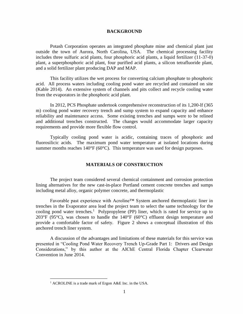
BACKGROUND
Potash Corporation operates an integrated phosphate mine and chemical plant just
outside the town of Aurora, North Carolina, USA. The chemical processing facility
includes three sulfuric acid plants, four phosphoric acid plants, a liquid fertilizer (11-37-0)
plant, a superphosphoric acid plant, four purified acid plants, a silicon tetrafluoride plant,
and a solid fertilizer plant producing DAP and MAP.
This facility utilizes the wet process for converting calcium phosphate to phosphoric
acid. All process waters including cooling pond water are recycled and contained on site
(Kable 2014). An extensive system of channels and pits collect and recycle cooling water
from the evaporators in the phosphoric acid plant.
In 2012, PCS Phosphate undertook comprehensive reconstruction of its 1,200-lf (365
m) cooling pond water recovery trench and sump system to expand capacity and enhance
reliability and maintenance access. Some existing trenches and sumps were to be relined
and additional trenches constructed. The changes would accommodate larger capacity
requirements and provide more flexible flow control.
Typically cooling pond water is acidic, containing traces of phosphoric and
fluorosilicic acids. The maximum pond water temperature at isolated locations during
summer months reaches 140°F (60°C). This temperature was used for design purposes.
MATERIALS OF CONSTRUCTION
The project team considered several chemical containment and corrosion protection
lining alternatives for the new cast-in-place Portland cement concrete trenches and sumps
including metal alloy, organic polymer concrete, and thermoplastic
Favorable past experience with Acroline™ System anchored thermoplastic liner in
trenches in the Evaporator area lead the project team to select the same technology for the
cooling pond water trenches.1 Polypropylene (PP) liner, which is rated for service up to
203°F (95°C), was chosen to handle the 140°F (60°C) effluent design temperature and
provide a comfortable factor of safety. Figure 2 shows a conceptual illustration of this
anchored trench liner system.
A discussion of the advantages and limitations of these materials for this service was
presented in “Cooling Pond Water Recovery Trench Up-Grade Part 1: Drivers and Design
Considerations,” by this author at the AIChE Central Florida Chapter Clearwater
Convention in June 2014.
1 ACROLINE is a trade mark of Ergon A&E Inc. in the USA.

2
Figure 1. Partial schematic of the Aurora mill flowsheet (bucket wheel excavator
has since been replaced with other technology). (Kable 2014)

3
Figure 2. Conceptual illustration of anchored thermoplastic trench liner with
cutaway detail.
FOAM CONCRETE FORMWORK DISPOSAL
The new pond water recovery trenches were designed with rounded rather than
square bottoms. The shape was chosen for three reasons:
1. Minimize build-up of gypsum-laden sediment in the corners of the trenches
2. Simplify the liner fabrication – minimize seams and corner welds
3. Reduce the risk of air entrapment during concrete back-filling
Concrete casting forms were cut from light-weight expanded polystyrene foam
rather than wood or metal as shown in Figures 3 and 4, because they could easily be cut to
fit the shape of the round-bottom trenches and provided uniform resistance to deflection, top
to bottom.
Figure 3. Inverted trench liner sections with foam forms in fabrication shop2
2 Photo courtesy of Plastek Werks, Inc., Cleveland, Georgia.

4
Figure 4. Trench liner section with foam formwork ready for concrete backfill3
Recycling the large volume of expanded polystyrene foam presented unanticipated
challenges. Because the foam was contaminated with concrete residue and chemicals with
which in came into contact during use, foam recycling facilities declined to accept it. In
addition, the logistics of transporting the large volume of foam to a distant recycling facility
were economically unfavorable. Alternative disposal arrangements were made.
FORMWORK DISPLACEMENT DURING CONCRETE PLACEMENT
The combined weight of the liners and formwork was lighter than the volume of
concrete they displaced creating an unbalanced buoyant force. The liners and formwork
tended to float on the fresh concrete backfill.
While the rounded shape of the trench bottoms facilitated the escape of air caught
under the liners during placement of the concrete, it did not offer substantial lateral
anchoring to help prevent the liners’ floating. In some cases, the walls of the liners were
well restrained, while the bottoms of the liners freely deflected, vertically displacing the
foam formwork.
Once these dynamics were well understood, the floating risk was easily managed.
Placing the concrete in 2 or 3 lifts provided adequate anchoring to prevent floating. Figure
5 shows a successfully installed section of the trench liner.
3 Photo courtesy of Ergon A&E Inc., Jackson, Mississippi.

5
Figure 5. Competed trench section before solid cover was installed.4
DAMS BETWEEN ACTIVE TRENCHES AND CONSTRUCTION AREAS
The project’s progression depends upon proper functioning of the knife gates (Figure
6) and removable dams (Figures 7 and 8), which will be used to isolate sections of the active
trench system as the new system is integrated with the old system and the old system is
phased out.
Figure 6. Knife gates in existing pond water trench.5
Both the knife gates and block gates were as effective as they were before the trench
was reconstructed and lined with polypropylene embedment liners, but no more so. They
routinely leaked a tolerable amount. Visual monitoring and passive hydrogen sulfide
monitors were used to manage risk of personnel exposure
4 Photo courtesy of Plastek Werks Inc., Cleveland, Georgia. 5 Photo courtesy of PCS Phosphates, Aurora, North Carolina.

6
Figure 7. Old block gates. New gates will be covered in anchored plastic.6
Figure 8. Recessed channels in trench ID, designed to accommodate the inflatable
bladder between the trench ID and block gate OD.7
NONDESTRUCTIVE LEAK LOCATION AND REPAIR WORK
The liner installation procedures and construction details (Figures 9 and 10) indicate
that the liners are to be secured to the concrete casting forms for the pump pit walls so as to
avoid making holes in the liners that would be difficult to locate and repair once the
formwork is stripped. In practice, this ideal proved difficult to attain, as the black liners
6 Photo courtesy of PCS Phosphate, Aurora, North Carolina. 7 Photo courtesy of Plastek Werks Inc., Cleveland, Georgia.

7
grew larger and smaller as the sun rose and set each day in the expansive, unshaded
construction area.
Figure 9. Liner installation detail – section view through wall showing attachment
of liners to formwork at butted joints between liner panels.
During the heat of the day when the liners were largest, they would deflect away
from the formwork, as show in Figure 11. As temperatures cooled, the liners would
sometimes detach from the formwork. An abundance of nails were used to secure the liners
and prevent concrete from getting between the liners and formwork as it was placed.
Figure 10. Liner installation detail – section view through wall showing mechanism
for hanging liners from the top of the formwork.
WIRE LOOP NAIL
WOODEN CON-CRETE FORM
LINER
CONCRETE
WIRE LOOP
NAIL
END PROFILE
EXTRUSION WELD
LINER
CONCRETE
WOODEN CONCRETE FORM

8
Figure 11. Anchored liner panels, attached to concrete formwork for pump pit
walls8
To locate holes that were invisible, a 32 kV DC holiday detector proved very
effective. In accordance with DVS 2206-4 – Non-destructive tests on tanks, apparatus and
piping made of thermoplastics – Testing with electrical high voltage, the liner was spark
tested with 75-125 kV output, 15-25 kV per mil of liner thickness. Locations producing a
spark were marked for repair with white circles drawn on the black liner as shown in Figure
12. Holes were sealed by means of extrusion welding as shown in Figure 13.
Figure 12. The locations of sparks were marked for repair with a white pen.9
8 Photo courtesy of Ergon A&E Inc., Jackson, Mississippi. 9 Photo courtesy of Plastek Werks Inc., Cleveland, Georgia.

9
Figure 13. Holidays were sealed by means of extrusion welding.10
CONCLUSION
The PCS Phosphate encountered a number of challenges during reconstruction of its
phosphoric acid pond water recovery trenches and sumps, some of which were specific to its
choice of anchored thermoplastic concrete protective liners. Difficulties were encountered
preventing the liners from floating during concrete placement; disposing of a large volume
of expanded polystyrene foam; isolating sections of the system while phasing in completed
sections and phasing out old sections; and locating and repairing nail holes through the liner.
None of these difficulties proved insurmountable. The occurrence of some of them
decreased as the crews gained experience working with the liners. Close collaboration
between the general civil contractor, Trader Construction, and plastic fabricator, Plastek
Werks, assured safety, quality, and functionality.
Final phases of construction were underway at the time of this paper’s publication.
Information about performance in service is not available at this time.
REFERENCES
Kable (2014). Retrieved from http://www.mining-technology.com/projects/aurora-
phosphate-mine/
Kable (2014). Retrieved from http://www.mining-technology.com/projects/aurora-
phosphate-mine/aurora-phosphate-mine4.html
10 Photo courtesy of Plastek Werks Inc., Cleveland, Georgia.