
COOL ONE - dmeeu.com · Cool-One 5 Introduction 7 Probes 9 Distributor System 13 Heated Nozzle...
40
COOL ONE
Transcript of COOL ONE - dmeeu.com · Cool-One 5 Introduction 7 Probes 9 Distributor System 13 Heated Nozzle...

COOL ONE

02/0
2/20
17
02/0
2/20
17
ORDER ONLINE:estore.milacron.com
Or call ourCustomer Support Agents
for easy processing.
ATP: 0800 301 060F: 0800 401 020
BEP: +32 (0) 15 28 87 30F: +32 (0) 15 40 51 17
CHP: +41 0848 567 364F: +41 0848 567 365
CZP: 800 142 451 | +420 572 151 754F: 800 142 450 | +420 571 611 996
DEP: 0800 664 82 50 | +49 (0) 2351 437 0
F: 0800 664 82 51 | +49 (0) 2351 437 [email protected]
ESP: 900 900 342F: 900 900 343
FRP: +33 1 49 93 92 23F: +33 1 49 93 92 22
HUP: 0680 205 003 | +32 15 28 87 30
F: +32 15 40 51 [email protected]
ITP: 800 089 734F: 800 089 735
NLP: +31 (0) 20 654 5571F: +31 (0) 20 654 5572
PLP: +800 331 1312 | +32 15 21 50 92F: +800 331 1313 | +32 15 40 51 92
PTP: 800 207 900F: 800 207 901
SKP: 0800 142 451 | +420 572 151 754F: 0800 142 450 | +420 571 611 996
UKP: +44 2071 3300 37F: +44 2071 3300 36
Other CountriesP: +32 15 28 87 30F: +32 15 40 51 17

02/0
2/20
17
02/0
2/20
17
1
Cool-One 5
Introduction 7
Probes 9
Distributor System 13
Heated Nozzle Adapters 15
Construction 17
Construction Instructions 18
Start up 21
Guidelines 22
Accessories 25
Wiring Instructions 26
Thermocouple Accessories 27
Power Accessories 28
Index 33
Alphabetical Index 34
Last
revi
ew: 0
3/02
/17

02/0
2/20
17
02/0
2/20
17
2 estore.milacron.com
THE POWER OFPOSSIBILITIES.
At DME - a Milacron company - we see ourselves as problem solvers. A global integrated team that is driven by the desire to help each customer’s “what ifs” come to life.

02/0
2/20
17
02/0
2/20
17
3 estore.milacron.com
Tom GoekeCEO, MILACRON
“We want customers calling us with their toughest problems and wildest ideas. We are in the business of creating solutions and realizing aspirations – of building what used to be impossible.”
A GLOBAL TEAM,WORKING AS ONE.Milacron has a global perspective on what matters in manufactur-ing. With over 15 manufacturing facilities in six countries, we sell our plastics processing solutions in over 100 countries across six con-tinents. We have an installed base of 40,000 machines, 153,000 hot runners and over 3.5 million square feet of manufacturing space. We put this know-how to work every day to improve productivity, cut costs, increase energy efficiency, eliminate scrap, and reduce cycle times across a diverse range of in-dustries. Behind it all is our people – caring, committed and creative – who build long-term relationships with our customers.
From automobiles and appliances to milk jugs and toothbrushes, DME technologies and services help the
world’s leading companies make your favorite products.
Success in today’s global market starts with the best product, at the best price, in the required time frame. To achieve this, DME pro-vides customers with the best blend of manufacturing, outsourcing and strategic partners, managed to be delivered right on time anywhere in the world using contemporary, so-phisticated techniques.
DME delivers a variety of mold components available in all regional standards. Thousands of high per-formance, off-the-shelf and engi-neered solutions let our customers spend more time on valuable cavity work. Along with a comprehensive line of equipment and supplies, we provide the high quality products
you need to speed up assembly and simplify operations.
Only DME can provide customers with the worldwide resources re-quired to compete in the market of Injection Molds & Components, Hot and Cold Runner spare parts as well as in Die Set Molds & Components or Surface Finishing Technologies.
Today, DME is proud to be able to provide complete turnkey solutions, partnering with fellow Milacron companies such as Mold-Masters runnerless systems, Tirad high pre-cission custom plates (including DME Standard components) and Ferromatik machines.

02/0
2/20
17
02/0
2/20
17
4

02/0
2/20
17
02/0
2/20
17
5
Cool-One
02/0
2/20
17
02/0
2/20
17
6 estore.milacron.com
COOL-ONE
WHAT IS A DME COOL-ONE SYSTEM?
INTERNALLY HEATED
ONE OR MULTI-CAVITY
INSULATING BARRIER
HIGHER EFFICIENCY
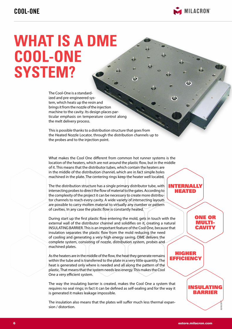
The Cool-One is a standard-ized and pre-engineered sys-tem, which heats up the resin and brings it from the nozzle of the injection machine to the cavity. Its design places par-ticular emphasis on temperature control along the melt delivery process.
This is possible thanks to a distribution structure that goes from the Heated Nozzle Locator, through the distribution channels up to the probes and to the injection point.
What makes the Cool One different from common hot runner systems is the location of the heaters, which are not around the plastic flow, but in the middle of it. This means that the distributor tubes, which contain the heaters are in the middle of the distribution channel, which are in fact simple holes machined in the plate. The centering rings keep the heater well located.
The the distribution structure has a single primary distributor tube, with intersecting probes to direct the flow of material to the gates. According to the complexity of the project it can be necessary to create more distribu-tor channels to reach every cavity. A wide variety of intersecting layouts are possible to carry molten material to virtually any number or pattern of cavities. In any case the plastic flow is constantly heated.
During start up the first plastic flow entering the mold, gets in touch with the external wall of the distributor channel and solidifies on it, creating a natural INSULATING BARRIER. This is an important feature of the Cool One, because that insulation separates the plastic flow from the mold reducing the need of cooling and generating a very high energy saving. DME delivers the complete system, consisting of nozzle, distribution system, probes and machined plates.
As the heaters are in the middle of the flow, the heat they generate remains within the tube and is transferred to the plate in a very little quantity. The heat is generated only where is needed and all along the pattern of the plastic. That means that the system needs less energy. This makes the Cool One a very efficient system.
The way the insulating barrier is created, makes the Cool One a system that requires no seal rings; in fact it can be defined as self-sealing and for the way it is generated it makes leakage impossible.
The insulation also means that the plates will suffer much less thermal expan-sion / distortion.

02/0
2/20
17
02/0
2/20
17
7 estore.milacron.com
TEMPERATURE CONTROLLERS
For being self-sealing and having less thermal stress, it requires less maintenance.
The features mentioned before make the Cool One a solid system, which is able to run for years, without having to bench the tool.
An important feature that the Cool One shares with common hot runner systems, is that it allows great material savings. almost 100% of the plastic entering the system is transformed into final product.
As any hot runner system it is suited for use in single or multi cavity molds and generally speaking it suits most of the possible applications for hot runners on the market and its mounting is very easy.
If you compare the Cool One with any mold with non heated runners, the quality of plastic parts is much better and the cycle time is shorter: the same advantages you look for in a Hot Runner system, but in a cheaper and more solid solution.
Our experts will draw the system for you. DME designs the best solution for you based on the main requirements of your project (plastic mate-rial, number of cavities etc.) and provides you the 3D and 2D drawings necessary for your approval.
The Cool One is a standard system that makes it easy for the designer to build the mold as there is no special parts required; the design is much easier. DME delivers not only standard system, we can do also specials. Please get in touch with our special projects department at their email DMEEU_SpecialProjects@dmeeu.
com and ask for feasibility.
The Cool One is not recommended on technical material, charged materials and if color changed is needed.
The heating elements are controlled by stan-dard DME temperature controller systems. More info on our website (www.dmeeu.com), eSTORE or ask for our Temperature Controllers brochure.
GREAT MATERIAL SAVINGS
NO LEAKAGE
BETTER QUALITY
LESS MAIN TENANCE
STANDARD SYSTEM
TEMPERATURE CONTROLLERS
INTRODUCTION

02/0
2/20
17
02/0
2/20
17
8 estore.milacron.com
AFP(P) RFACTFA
AFIP
AFIP
AFM (MPT + AFTC)
3-4-5 (TC)
(TC)
EC
AS
HTHCTC
WTUBHAWTODIHRDR
DFHMBAF
RAFFHSASF
}EHM
WRPSHBA HR
HNS
DR
AB ABSR
WRI DS
CAD
refe
renc
e po
int
COOL-ONE
Cool-One system - Basic conceptInfo

02/0
2/20
17
02/0
2/20
17
9 estore.milacron.com
A
ØC
ØB
15 M
in.
H
( ) I
ØJ *
K
ØD1
F
E
T
3 M
ax.
8 M
in.
G
Min.12mm (Maxi)Min.10mm (Standard)Min. 8mm (Mini)
Ø0.
02
0.02
X
Ø0.02
N8
Y
N8
0.02
-0,2
Y
Y
X
*M
30
R
ØP
Q
ØB
A
ØC
ØB
0,2
max
. Cyl O
60
15 M
in.
I
X
Ø0.02
N8
Y
M = Top view Cable exit 90°M = Draufsicht Ausfräsung fur 90° KabelausgangM = Bovenaanzicht Uitfrezing voor kabeluitgang 90°M = Vue du dessus Fraisage pour sortie de câble 90°
32
10
L
7
Ø 1
4
A
ASF
P
B AF HM
AFTC
Ø18
Ø d
L
7
Ø 1
4
A
ASF
P
B AF HM
AFTC
Ø18
Ø d
L
7
Ø 1
4
A
ASF
P
B AF HM
AFTC
Ø18
Ø d
L
7
Ø 1
4
A
ASF
P
B AF HM
AFTC
Ø18
Ø d
AFR ASF P AFTC BAF HM/EHM
CAD
refe
renc
e po
int
PROBES
Technical information AFP MINI PROBE
REF d L Watt 230V Amp.AFTC 0825 E 8 50 140 0,6AFTC 0826 E 8 65 185 0,8AFTC 0827 E 8 85 215 0,9AFTC 0828 E 8 110 300 1,3
To be ordered seperatelyAFTC + TC* AFR* WRI*
REF REF REF REFAFP 201 N AFTC 0825 E AFR 3114
WRI 92AFP 251 N AFTC 0826 EAFP 271 N AFTC 0827 E AFR 3414AFP 291 N AFTC 0828 E
REF AAFP 201 N 58AFP 251 N 73AFP 271 N 93AFP 291 N 118
AFP is built up by following itemsP ASF** BAF HM
REF REF REF REF REFAFP 201 N P 201 N
ASF 3 N BAF 10 N HM 22AFP 251 N P 251 NAFP 271 N P 271 NAFP 291 N P 291 N
Regular AFP probe is suited for unfilled material.In case you work with filled material, ask for a TiN coated probe.The AFP probe is a kit consisting of P, ASF, BAF and HM; see below for more information.

02/0
2/20
17
02/0
2/20
17
10 estore.milacron.com
A
ØC
ØB
15 M
in.
H
( ) I
ØJ *
K
ØD1
F
E
T
3 M
ax.
8 M
in.
G
Min.12mm (Maxi)Min.10mm (Standard)Min. 8mm (Mini)
Ø0.
02
0.02
X
Ø0.02
N8
Y
N8
0.02
-0,2
Y
Y
X
*M
30
R
ØP
Q
ØB
A
ØC
ØB
0,2
max
. Cyl O
60
15 M
in.
I
X
Ø0.02
N8
Y
M = Top view Cable exit 90°M = Draufsicht Ausfräsung fur 90° KabelausgangM = Bovenaanzicht Uitfrezing voor kabeluitgang 90°M = Vue du dessus Fraisage pour sortie de câble 90°
32
10
L
7
Ø 1
4
A
ASF
P
B AF HM
AFTC
Ø18
Ø d
L
7
Ø 1
4
A
ASF
P
B AF HM
AFTC
Ø18
Ø d
L
7
Ø 1
4
A
ASF
P
B AF HM
AFTC
Ø18
Ø d
L
7
Ø 1
4
A
ASF
P
B AF HM
AFTC
Ø18
Ø d
AFR ASF P AFTC BAF HM/EHM
CAD
refe
renc
e po
int
Technical informationAFP STANDARD PROBE
PROBES
Regular AFP probe is suited for unfilled material.In case you work with filled material, ask for a TiN coated probe.The AFP probe is a kit consisting of P, ASF, BAF and HM; see below for more information.
REF AAFP 301 N 74AFP 401 N 91AFP 501 N 118AFP 601 N 143
AFP is built up by following itemsP ASF** BAF HM
REF REF REF REF REFAFP 301 N P 301 N
ASF 4 N BAF 12 N EHM 2730AFP 401 N P 401 NAFP 501 N P 501 NAFP 601 N P 601 N
REF d L Watt 230V Amp.AFTC3022E 9,52 66 190 0,8AFTC3032E 9,52 83 240 1,0AFTC3042E 9,52 110 310 1,4AFTC3052E 9,52 136 390 1,7
To be ordered seperatelyAFTC + TC* AFR* WRI*
REF REF REF REFAFP 301 N AFTC3022E AFR 3416
DS 1011AFP 401 N AFTC3032EAFP 501 N AFTC3042E AFR 4016AFP 601 N AFTC3052E

02/0
2/20
17
02/0
2/20
17
11 estore.milacron.com
A
ØC
ØB
15 M
in.
H
( ) I
ØJ *
K
ØD1
F
E
T
3 M
ax.
8 M
in.
G
Min.12mm (Maxi)Min.10mm (Standard)Min. 8mm (Mini)
Ø0.
02
0.02
X
Ø0.02
N8
Y
N8
0.02
-0,2
Y
Y
X
*M
30
R
ØP
Q
ØB
A
ØC
ØB
0,2
max
. Cyl O
60
15 M
in.
I
X
Ø0.02
N8
Y
M = Top view Cable exit 90°M = Draufsicht Ausfräsung fur 90° KabelausgangM = Bovenaanzicht Uitfrezing voor kabeluitgang 90°M = Vue du dessus Fraisage pour sortie de câble 90°
32
10
L
7
Ø 1
4
A
ASF
P
B AF HM
AFTC
Ø18
Ø d
L
7
Ø 1
4
A
ASF
P
B AF HM
AFTC
Ø18
Ø d
L
7
Ø 1
4
A
ASF
P
B AF HM
AFTC
Ø18
Ø d
AFR ASF P AFTC BAF HM/EHM
CAD
refe
renc
e po
int
Technical information AFP MAXI PROBE
PROBES
Regular AFP probe is suited for unfilled material.In case you work with filled material, ask for a TiN coated probe.The AFP probe is a kit consisting of P, ASF, BAF and HM; see below for more information.
REF AAFP 502 N 115AFP 602 N 140AFP 702 N 168AFP 802 N 198AFP 902 N 248AFP 1002 N 320AFP 1102 N 370
AFP is built up by following itemsP ASF** BAF HM
REF REF REF REF REFAFP 502 N P 502 N
ASF 5 N BAF 16 N EHM 3215
AFP 602 N P 602 NAFP 702 N P 702 NAFP 802 N P 802 NAFP 902 N P 902 NAFP 1002 N P 1002 NAFP 1102 N P 1102 N
REF d L Watt 230V Amp.AFTC 1210 E 12,5 104 305 1,4AFTC 1212 E 12,5 130 365 1,6AFTC 1215 E 12,5 162 440 1,9AFTC 1218 E 12,5 190 515 2,2AFTC 1223 E 12,5 242 645 2,8AFTC 1230 E 12,5 312 930 4,1AFTC 1236 E 12,5 362 1300 5,5
To be ordered seperatelyAFTC + TC* AFR* WRI*
REF REF REF REFAFP 502 N AFTC 1210 E
AFR 4022 DS 1314
AFP 602 N AFTC 1212 EAFP 702 N AFTC 1215 EAFP 802 N AFTC 1218 EAFP 902 N AFTC 1223 E
AFP 1002 N AFTC 1230 EAFP 1102 N AFTC 1236 E

02/0
2/20
17
02/0
2/20
17
12 estore.milacron.com
L
M ØdM
L
SW
ØB
ØA
I
ØC
I
ØB
ØA
I
ØC
I
MM
ød
SW
ød
SW
T TTT
SWSW
M M
ød
øD
97
SW
150150
SW
97
ØD
Ød
TT
**
T
Ød
ØD
T
**
CAD
refe
renc
e po
int
REF d M L SWMini BAF10N 6 M10x1 23 9
Standard BAF12N 8 M12x1 30 10Maxi BAF16N 10 M16x1 35 14
REF A B C l ForAFR 3114 31 23 13,5 3 AFP MINI + AFIPAFR 3414 34 26 13,5 3 AFP MINI + AFIPAFR 3416 34 26 15,5 3 AFP STAN. + AFIPAFR 4016 40 32 15,5 3 AFP STAN. + AFIPAFR 4022 40 32 21,5 3 AFP MAXI
REF Type M T d SWMicro HM 22 A 12,5 14,0 12Mini HM 22 A M10x1 12,5 14,0 12
Standard EHM 2730 B M12x1 15,0 16,0 14Maxi EHM 3215 B M16x1 15,0 19,5 17
REF D d TASF 1 N 15,5 10,5 2ASF 2 N 18 13,0 2ASF 3 N 18 14,5 3ASF 4 N 22 16,5 4ASF 5 N 28 22,5 4
REF D d TRAF 3-062 15,5 11,6 1,57RAF 4-062 18,14 11,9 1,57RAF 5-062 18,14 14,3 1,57
**grind this face to suit
REF Type D d SWMicro WRI 92 a 18 12 -Mini WRI 92 a 18 12 -
Standard DS 1011 b - 7 14Maxi DS 1314 b - 9 17
Stop sleeves for cartridge heaters
Centering rings
Hold down nuts
Spacer washers
Keys for hold down nuts
Spacer washers
BAF HM / EHM WRI / DS
AFR ASF RAF
PROBES - ACCESSORIES

02/0
2/20
17
02/0
2/20
17
13 estore.milacron.com
FHS DF HT EC ASEC HCTC
L
ØD
Ød
25* L
ØD
CAD
refe
renc
e po
int
DISTRIBUTOR SYSTEM
Distributor system Cool-One Info
HT HCTCDistributor tubes Cartridge heaters with TC type ‘J’ (Teflon sealed, waterproof)
* Unheated zone
REF D d L
MIN
I
HT 03 30 N
16 9,52
300HT 03 40 N 400HT 03 50 N 500HT 03 60 N 600
REF D d L
STAN
DARD
HT 04 20 N
22,22 12,7
200HT 04 30 N 300HT 04 40 N 400HT 04 50 N 500HT 04 60 N 600HT 04 70 N 700HT 04 80 N 800HT 04 90 N 900
REF D d L
MAX
I
HT 05 30 N
41,27 15,87
300HT 05 40 N 400HT 05 50 N 500HT 05 60 N 600HT 05 70 N 700HT 05 80 N 800
HT 05 100 N 1000HT 05 120 N 1200
REF D LWatt 230V
Amp
MIN
I
HCTC 03-4E
9,52
102 350 1,6HCTC 03-45E 114 370 1,6HCTC 03-5E 127 435 1,9HCTC 03-55E 140 470 2,1HCTC 03-6E 152 490 2,1HCTC 03-65E 165 515 2,2HCTC 03-7E 178 525 2,3HCTC 03-8E 203 600 2,6HCTC 03-9E 229 710 3,1
REF D LWatt 230V
Amp
STAN
DARD
HCTC 04-05E
12,7
127 425 1,9HCTC 04-6E 152 435 1,9HCTC 04-7E 178 480 2,1HCTC 04-8E 203 600 2,6HCTC 04-9E 229 710 3,1HCTC 04-10E 254 765 3,3HCTC 04-11E 279 850 3,7HCTC 04-12E 305 940 4,1HCTC 04-13E 330 1040 4,5HCTC 04-14E 356 1110 4,8HCTC 04-15E 381 1200 5,2HCTC 04-16E 406 1310 5,7HCTC 04-17E 432 1420 6,2HCTC 04-18E 457 1475 6,4
REF D LWatt 230V
Amp
MAX
I
HCTC 05-6E
15,87
152 570 2,5HCTC 05-7E 178 670 3,0HCTC 05-8E 203 810 3,6HCTC 05-9E 229 930 4,1HCTC 05-10E 254 1060 4,6HCTC 05-11E 279 1190 5,2HCTC 05-12E 305 1310 5,7HCTC 05-13E 330 1440 6,3HCTC 05-14E 356 1560 6,8HCTC 05-15E 381 1690 7,3HCTC 05-16E 406 1815 7,8HCTC 05-17E 432 1935 8,4HCTC 05-18E 457 2065 9,0HCTC 05-19E 483 2200 9,5HCTC 05-20E 508 2320 10,0HCTC 05-21E 533 2450 10,7HCTC 05-22E 559 2570 11,2HCTC 05-23E 584 2690 11,7HCTC 05-24E 610 2820 12,2HCTC 05-25E 635 2940 12,8
REF D LWatt 230 V
Amp
HCTC 03-10E
9,52
254 775 3,3HCTC 03-11E 279 785 3,5HCTC 03-12E 305 830 3,7HCTC 03-13E 330 885 3,9HCTC 03-14E 356 905 4,0HCTC 03-15E 381 1200 5,2HCTC 03-16E 406 1310 5,7HCTC 03-17E 432 1420 6,2HCTC 03-18E 457 1530 6,7
REF D LWatt 230 V
Amp
HCTC 04-19E
12,7
483 1575 6,8HCTC 04-20E 508 1661 7,2HCTC 04-21E 533 1750 7,6HCTC 04-22E 559 1870 8,2HCTC 04-23E 584 1980 8,6HCTC 04-24E 610 2200 9,6HCTC 04-25E 635 2280 9,9HCTC 04-26E 660 2450 10,7HCTC 04-27E 686 2550 11,1HCTC 04-28E 711 2635 11,5HCTC 04-29E 737 2840 12,3HCTC 04-30E 762 2940 12,8HCTC 04-31E 787 3150 13,7
REF D LWatt 230 V
Amp
HCTC 05-26E
15,87
660 3070 13,4HCTC 05-27E 686 3190 13,9HCTC 05-28E 711 3320 14,4HCTC 05-29E 737 3475 15,2HCTC 05-30E 762 3550 15,5HCTC 05-31E 787 3700 16,1HCTC 05-32E 813 3825 16,6HCTC 05-33E 838 3945 17,1HCTC 05-34E 864 4065 17,7HCTC 05-35E 889 4200 18,3HCTC 05-36E 914 4330 18,8HCTC 05-37E 940 4480 19,4HCTC 05-38E 965 4590 20,0HCTC 05-39E 991 4700 20,4HCTC 05-40E 1016 4820 20,9HCTC 05-41E 1041 4950 21,5HCTC 05-42E 1067 5000 21,7HCTC 05-43E 1092 5070 22,1HCTC 05-44E 1118 5070 22,1HCTC 05-45E 1143 5070 22,1

02/0
2/20
17
02/0
2/20
17
14 estore.milacron.com
FHS DF HT EC ASEC HCTC
Ød
L
M
L3
ØD
i
Lo
ØD
m
ØD
a
Ød
Ød1
M
L
ØD
L3
R
Ød
6
L
M
SW
CAD
refe
renc
e po
int
DISTRIBUTOR SYSTEM
Distributor system - AccessoriesInfo
AS
DF / WZ
EC
FHS
Stop screws
Positioning springs
End caps
Spring retainers
REF L M d L3
Mini AS 12 N 35 M12 8 12
Standard AS 16 N 50 M16 11 16
Maxi AS 20 N 50 M20 14 20
REF Do Lo Di Dm dMini DF930 9 30 7,4 8,2 0,8
Standard WZ80611255 12 55 9 10,5 1,5Maxi WZ80611500550 15 55 12 13,5 1,5
REF D d1 L L3 R M
Mini EC 03 N 24 16 25 17
4,5
M12EC 03/5 N 32
Standard EC 04 N 32 22,2238 26
M16EC 04/5 N 40
Maxi EC 05 N 50 41,27 M20EC 05/5 N 50 32
REF L M d SWMini FHS 12 17 M12 7 17
Standard FHS 16 20 M16 10 19Maxi FHS 20 23 M20 12 24

02/0
2/20
17
02/0
2/20
17
15 estore.milacron.com
DI
WTO
HR
DR
BHA
WTU
Min
.12
16
Ø71 (4xholes-Boh rungen-gaten-t rous)
ØD H9
Ød H13
Ø8 H7
34
Ø50
Air
gap
0.5m
m
0.3
Min
.5
Ø90 H9
2
HRDI WTO BHA DRWTU
21
Ø24
24
Ø32
NachbearbeitenNabewerkenA ajuster
To be adjusted
E 8 x 100
M8
Lufts
palt
0.5m
mLu
chts
plee
t 0.5
mm
Eca
rtem
ent 0
.5m
m
ØA
ØB
5
L
16
ØD
ØC
E
ØB
22
C
Ø10
Ø9
D
12
F
22
ØA
5
ØD
ØE
ØA
5
ØB
B
Ø71
(4x
)
8,5
45
ØA
Ø90
5
15
ØD
A
8
CAD
refe
renc
e po
int
HEATED NOZZLE ADAPTERS
Heated nozzle adapters BHA
REF dH13 DH9BHA 30X30 N 16 50BHA 40X30 N 18 60BHA 40X40 N 18 60
REF A B C D L
BHA 30X30N 30 20 6 14 55BHA 40X30N 40 30 8 16 55BHA 40X40N 40 30 8 16 65
REF A B C D E FWatt 230V
DI 30X30 30 40 30 35 50 70 330DI 40X30 40 50 30 40 55 75 380DI 40X40 40 50 40 40 55 75 490
REF E D
WTU 50 50 14WTU 60 60 16
REF A DDR 40 30 90DR 90 60 90
REF A DHR 30 30 20HR 40 40 30
REF A DWTO 30 30 20WTO 40 40 30
Body for heated nozzle adapters
Insulating disc (upper)
Band heaters with TC type ‘J’
Nozzle locaters
Insulating disc (lower)
Distance bushing
BHA DI WTU
WTO HR DR
If the radius is required it can be realized by the mold maker

02/0
2/20
17
02/0
2/20
17
16 estore.milacron.com
B
Ø71
(4x
)
8,5
45
ØA
Ø90
5
15
ØD
A
8
DR
HR
HBAR3
Min
.12
min
.15.
5m
in.5
*
Ø12 H7
Ø40 H7
Ø26
2
Ø8 H7
3M
in.5
Ø71 (4xholes-Bohrungen-gaten-trous)
Ø90 H9
E8 x 100
M8
DRHBAHR WRPS HNSA
ir ga
p 0.
5mm
Luft
spal
t 0.5
mm
Luch
tspl
eet 0
.5m
mEc
arte
men
t 0.5
mm
NachbearbeitenNabewerkenA ajuster
To be adjusted
ØD
107
L
L1
8
L
Ø12
Ø6
ØD
8
ØID
L
ØD
35 1000
CAD
refe
renc
e po
int
HEATED NOZZLE ADAPTERS
Heated nozzle adaptersBHA
REF A DDR 40 30 90DR 90 60 90
REF L L1 D
HBA 7640 75,5 67,5 40
REF L D1 DWatt 230 V
WRPS 42/91 57 11,98 18,4 300
REF D LHNS 40 40 15
HNS 40-50 40 50
REF A DHR 40 40 30
Distance bushing
Adapter shanks Square coil heaters with thermocouple type ‘J’
Nozzle locaters Spacer rings
DR HR HNS
HBA WRPS

02/0
2/20
17
02/0
2/20
17
Construction

02/0
2/20
17
02/0
2/20
17
18 estore.milacron.com
AFP(P) RFACTFA
AFIP
AFIP
AFM (MPT + AFTC)
3-4-5 (TC)
(TC)
EC
AS
HTHCTC
WTUBHAWTODIHRDR
DFHMBAF
RAFFHSASF
}EHM
WRPSHBA HR
HNS
DR
AB ABSR
WRI DSCA
D re
fere
nce
poin
t
CONSTRUCTION INSTRUCTIONS
Guidelines for the construction of a distributor blockInfo
AMin dimensions:Without AFR With AFRMin. 23 mm (Micro) Min. 27,5 mm (Micro)Min. 27 mm (Mini) Min. 32 mm (Mini)Min. 30 mm (Standard) Min. 35 mm (Standard)Min. 40 mm (Maxi) Min. 41 mm (Maxi)
B45 mm (Micro)45 mm (Mini) Consult DME55 mm (Standard) according to90 mm (Maxi) the application
CExpansion allowance between end caps and distributortube: length ≤ 600 mm = 1,5 mmlength ≥ 600 mm = 3,0 mm
D5,5 mm (Mini)11,0 mm (Standard)11,0 mm (Maxi)
E20 mm (Mini)25 mm (Standard)25 mm (Maxi)
F45 mm (Micro)45 mm (Mini) Consult DME55 mm (Standard) according to90 mm (Maxi) the application
G70 mm (Micro)70 mm (Mini)80 mm (Standard)115 mm (Maxi)
H20 mm (Mini)25 mm (Standard)25 mm (Maxi)
ICenter distance probe to tube:Micro probesAFIP 3 13 mm with Mini distributor tube 16 mm with Standard distributor tubeAFIP 4 14 mm with Mini distributor tube 17 mm with Standard distributor tubeMini probesAFIP 5 15,3 mm with Mini distributor tube 18,4 mm with Standard distributor tubeAFIP (201-271) 16 mm with Mini distributor tubeAFP(201-291N) 19 mm with Standard distributor tube
Standard probesAFIP (301-601) 17 mm with Mini distributor tubeAFP (301-601N) 20 mm with Standard distributor tube 29,5 mm with Maxi distributor tubeMaxi probesAFP(502-1102N) 23 mm with Standard distributor tube 32,5 mm with Maxi distributor tube
JInsulating plate for cable protection: thickness 6 - 10 mm
KCenter distance tube to tube- 17 ± 0,5 mm for distributor tubes diameter 16- 23,5 ± 0,5 mm for distributor tubes diameter 22,22- 42,5 ± 0,5 mm for distributor tubes diameter 41,27- 20 ± 0,5 mm for combination diameter 16 withdiameter 22,22- 33 ± 0,5 mm for combination diameter 22,22 withdiameter 41,27
LCentering ringPosition: pin always opposite the distributor tube
MMinimum distance of the cooling lines to the distributorbore and/or probe bore = 10 mm.

02/0
2/20
17
02/0
2/20
17
19 estore.milacron.com
A
ØC
ØB
15 M
in.
H
( ) I
ØJ *
K
ØD1
F
E
T
3 M
ax.
8 M
in.
G
Min.12mm (Maxi)Min.10mm (Standard)Min. 8mm (Mini)
Ø0.
02
0.02
X
Ø0.02
N8
Y
N8
0.02
-0,2
Y
Y
X
*M
30
R
ØP
Q
ØB
A
ØC
ØB
0,2
max
. Cyl O
60
15 M
in.
I
X
Ø0.02
N8
Y
M = Top view Cable exit 90°M = Draufsicht Ausfräsung fur 90° KabelausgangM = Bovenaanzicht Uitfrezing voor kabeluitgang 90°M = Vue du dessus Fraisage pour sortie de câble 90°
32
10
CAD
refe
renc
e po
int
CONSTRUCTION INSTRUCTIONS
Construction instructions AFP
(*) Tube* Consult DME depending on the application
Type Mini Standard Maxi
REF AFP(201-291 N)
AFP (3016-601 N)
AFP(502-1102 N)
(*) Ø16 -> A 16 17 -
(*) Ø22,22 -> A 19 20 23
(*) Ø41,27 -> A 28,4 29,5 32,5
(*) Ø16 -> H 14,5 14,5 -
(*) Ø22,22 -> H 18,5 18,5 27,5
(*) Ø41,27 -> H - 27,5 27,5
(*) Ø16 -> J* 24 - -
(*) Ø22,22 -> J* 32 32 32
(*) Ø41,27 -> J*
B MIN 23 26 32
C H7 Ø31 Ø34 Ø40
D1 H7 Ø14 Ø15,9 Ø22
E Ø19,5 Ø24 Ø30,5
F M22 M27 M32x1,5
T MIN 27 30 40
G MIN 25 27,5 27,5
I AFR +0,020 3,0 3,0 3,0
K 3 4 4
MCable exit
Straight Straight Straight
O 1,5 2 2
P MIN 0,8 1,0 1,0
Q 80° 80° 90°
R 6 8 13
B larger with AFR

02/0
2/20
17
02/0
2/20
17
20 estore.milacron.com
02/0
2/20
17
02/0
2/20
17
Start up

02/0
2/20
17
02/0
2/20
17
22 estore.milacron.com
CAD
refe
renc
e po
int
MOLD CHECK-OUT1. Guidelines for zone numbering: Zone number 1 is the
probe closest to the “U” corner. This is stamped on the mold and indicates the position of the undersized lead-er pin. The numbers for the other probes run in the most logical order (mostly clockwise). The distributor bores are next and the one closest to the “U” corner takes the next number. The remainder of the distributor bores are numbered working up through the different levels with the heated adapter taking the last number.
2. Connect electric power and thermocouples according to the wiring diagram.
3. Connect mold to the mold temperature controller.4. Check mold cooling for operation.5. Switch on temperature controller6. Adjust in 50 °C increments until operating temperature
is reached.
GUIDELINES
Guidelines for the use of a distributor blockInfo
START-UP1. Bring machine cylinder up to required temperature,
purge cylinder and leave screw in forward position.2. With machine in “Manual” mode, open mold and bring
machine cylinder fully forward into molding position with machine nozzle in contact with the locator of the mold.
3. Set screw back pressure and RPM to maximum, and extrude material into distributor block until filled. Ma-terial should appear at gates. Screw will automatically recover, indicating that distributor block is full. (Setting the back pressure and screw RPM to max. are for filling block only and not for use during processing).
4. Turn on controllers with set points to the recommended melt temperature of the material being used.
5. When deviation meters have stabilized, the tempera-ture set points have been attained and normal molding can now begin.
6. During injection adjust the temperature of the distribu-tor, adaptor and machine so that perfect units are pro-duced.
SERVICING1. Screwing of the mold plate to the distributor plate
makes for easy access for mold separation. Remove fix-ing screws on the mold plate (fixed side), close press.
2. With mold closed, fix carrier or bolt to the mold plates. Open press slowly. Then one has access to all probes and gates. Remove any impurities at the gates. Close press. Remove carrier, replace fixing screws, open up mold. Screw mold plate to distributor plate.
CARTRIDGE HEATER REPLACEMENTDistributor cartridge heater:Switch off temperature controller, take out plug, cut off connection leads to the cartridge. Remove positioning screws and knock-out cartridge heater. It is not necessary to dismantle the mold.
Probe cartridge heater:Switch off temperature controller, take out plugs. Close press and remove fixing clamps of the fixed half of the

02/0
2/20
17
02/0
2/20
17
23 estore.milacron.com
CAD
refe
renc
e po
int
GUIDELINES
Guidelines for the use of a distributor block Info
mold, fix carrier or bolt to the mold plates. Open press slowly. Then one has free access to all probe cartridge heat-ers. Remove hold down nuts, remove heater and replace with new one. Make sure all wire constructions are satisfac-tory and no wires can be trapped. Slowly close press and replace fixing screws. Remove carrier or bolts and open press. Reconnect power and thermocouple cables.
ASSEMBLY GUIDELINES FOR HCTCConditions:Distributor bore and tube must be free from dirt, oil, and fats. Distance screw must be screwed into the correct posi-tion in the end caps. Wire channels must be large enough and all sharp edges removed.
Assembly :Caution! Do not use any assembly materials as heat con-ductive paste, etc.. for the cartridge heaters. 1. The distributor cartridge heaters are pushed into the
already assembled distributor tube until they reach the stop screw.Caution! The distributor cartridge heater must fit easily into the bore.
2. Thermocouple and power cables can then be connect-ed to the terminal housings.
3. Continuity checks on the connected heating elements should be carried out using a universal electrical meas-uring appliance. Caution! Before commissioning the hot-runner sys-tem, re-check that the distributor cartridge heaters lie against the stop screws.

02/0
2/20
17
02/0
2/20
17
24 estore.milacron.com
02/0
2/20
17
02/0
2/20
17
Accessories

02/0
2/20
17
02/0
2/20
17
26 estore.milacron.com
9
UU
1
11
8
12
10
2
3
4
7
6
5
CAD
refe
renc
e po
int
WIRING INSTRUCTIONS
Wiring instructions for DME heaters
1. Power wires can only be extended with crimp connectors (HWCC-1,2 and 5) and power wires of the same cross-section area (total length max. 8 m).
2. Fe-Co thermocouple wires can only be extended with Fe-Co wires. With the exception of the polarity of the extension cable (US standards: red = negative, white = positive; European standards: red = positive, blue = negative). One must take care that the thermocouple wires are in good contact with the cable joint.
3. Mold power input connector (PIC-24-G) and terminal mounting box (PTCX, PICX, PTC) must be connected with the protective conductor to the mold.
4. Take care that wiring is correct to the position of the modules.5. Use Ohm-meter to check each heater for proper function prior to starting the DME Hot Runnerless System.
Mold power input connector
REF PIC24G Zone Contr. No. 1 .............. A1, A2 2 .............. A3, A4 3 .............. B1, B2 4 .............. B3, B45-zone MF 5 .............. A5, B5 ................................. 6 .............. C1, C2 7 .............. C3, C48-zone MF 8 .............. D1, D2 ................................. 9 .............. D3, D4 10 .............. C5, D5 11 .............. E1, E212-zone MF 12 .............. E3, E4
Thermocouple connector
REF MTC5G REF MTC8G REF MTC12G
Zone Contr. No. Zone Contr. No. Zone Contr. No. + – + – + –1 .......................... 1, 6 1 ...................... 1, 9 1 ....................... 1, 132 .......................... 2, 7 2 ...................... 2, 10 2 ....................... 2, 143 .......................... 3, 8 3 ...................... 3, 11 3 ....................... 3, 154 .......................... 4, 9 4 ...................... 4, 12 4 ....................... 4, 165 .......................... 5, 10 5 ...................... 5, 13 5 ....................... 5, 17 6 ...................... 6, 14 6 ....................... 6, 18 7 ...................... 7, 15 7 ....................... 7, 19 8 ...................... 8, 16 8 ....................... 8, 20 9 ....................... 9, 21 10 .................. 10, 22 11 .................. 11, 23 12 .................. 12, 24
Wiring diagram Thermocouple cable
Socket contact
Socket contact
Socket contact
Pin contact
Mold power cable TC Wiring codeDIN + red/ - blueUSA + white / - redEUROPE + black / - white
Wiring instructionsInfo

02/0
2/20
17
02/0
2/20
17
27 estore.milacron.com
➊ ➋
CAD
refe
renc
e po
int
THERMOCOUPLE ACCESSORIES
MTC
C14610F
C14610A
Thermocouple connectors
Thermocouple cables
Male inserts
REF ZonesMTC5G 5MTC8G 8
MTC12G 12
REF a b c contactsC14610F0100011 83 93 43 10+C14610F0160011 103 113 43 16+C14610F0240011 130 140 43 24+
REF a b c contactsC14610A0101021 57 64 34 10+C14610A0161021 77,5 84,5 34 16+C14610A0241021 104 111 34 24+
REF a b c contactsC14610G0101061 51 73 43 10+C14610G0161061 61 93 43 16+C14610G0241061 61 119,5 43 24+
REF a b c contactsC14610B0101021 57 64 34 10+C14610B0161021 77,5 84,5 34 16+C14610B0241021 104 111 34 24+
REFC14610G0252002
REF Zones Cable lengthTC54-5G 5 4,5 mTC84-5G 8 4,5 m
TC124-5G 12 4,5 m
TC
C14610G
C14610B
VN02
Thermocouple cables
➊ Hoods end entry ➋ Hoods top entry
➊ Female inserts
to mold to frame
OE...
REF IdentificationOE160-5
FeCo Thermocouplescables(**tobeorderedperm.)16poles0,5mm2(FeCo)
OE240-5 24poles0,5mm2(FeCo)
REF Zones Cable lengthTC5DE 5 0,5 mTC8DE 8 0,5 m
TC12DE 12 0,5 m
➋ Female inserts (without contacts)
REFC14610B0250002
➋ Female socket contacts
REFVN02
Thermocouples cables
02/0
2/20
17
02/0
2/20
17
28 estore.milacron.com
➊
➋
CAD
refe
renc
e po
int
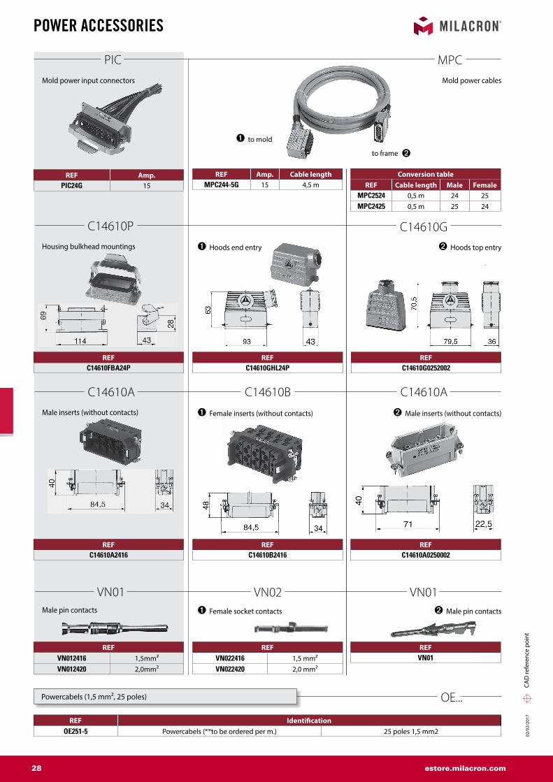
POWER ACCESSORIES
REF IdentificationOE251-5 Powercabels (**to be ordered per m.) 25 poles 1,5 mm2
Male pin contacts
VN01
PIC
C14610P
C14610A
Male inserts (without contacts)
Housing bulkhead mountings
Mold power input connectors
REFC14610FBA24P
REFC14610A2416
REF Amp.PIC24G 15
REFVN012416 1,5mm²VN012420 2,0mm²
Powercabels (1,5 mm², 25 poles) OE...
to mold
to frame
MPC
C14610G
C14610A
VN01
C14610B
VN02
Mold power cables
REF Amp. Cable lengthMPC244-5G 15 4,5 m
Conversion tableREF Cable length Male Female
MPC2524 0,5 m 24 25MPC2425 0,5 m 25 24
➊ Hoods end entry ➋ Hoods top entry
REFC14610GHL24P
REFC14610G0252002
➊ Female inserts (without contacts)
➊ Female socket contacts
➋ Male inserts (without contacts)
➋ Male pin contacts
REFC14610A0250002
REFC14610B2416
REFVN022416 1,5 mm²VN022420 2,0 mm²
REFVN01

02/0
2/20
17
02/0
2/20
17
29 estore.milacron.com
PIC-24
MTG-Gx*y
a
b c*
PIC-24
145*160
80
70 55*
MTC
PIC25Gx*y
a
b c*
CAD
refe
renc
e po
int
MOUNTING BOXES
Terminal mounting boxes for power and thermocouple connectors
Terminal mounting boxes for power and thermocouple connectors
Terminal mounting boxes for power and thermocouple connectors PICX
PTCX
PTC
REF a b c x y Installation possibilities forPTCX5K
70 70 55 243 258PIC24G / MTC5G
PTCX8K PIC24G / MTC8GPTCX12K PIC24G / MTC12G
REF Installation possibilities forPICX245K PIC24G / MTC5GPICX248K PIC24G / MTC8G
PICX2412K PIC24G / MTC12G
* Distance of mounting screws on the mold with M5 x 15.
* Distance of mounting screws on the mold with M5 x 15.
REF a b c x y Installation possibilities forPTC5TBG 105 60 38 205 220 PIC5G / MTC5GPTC8TBG 105 60 38 225 240 PIC8G / MTC8G
PTC12TBG 105 60 38 253 265 PIC12G / MTC12G
* Distance of mounting screws on the mold with M5 x 15.
UK only

02/0
2/20
17
02/0
2/20
17
30 estore.milacron.com
50*
40min
.
17.5 M4x15
R12.5E
*
D
C
B
A
16
32
35
25
106*
R12.5
F*
90103
150
3235
R1,25
R1,25
70
(4) M4 x 1540
40
CAD
refe
renc
e po
int
MOUNTING
Pocket for thermocouple connectors MTC...G
Pocket for mold power input connectors PIC24G
Note: Drawing depicts below flush mounting.For surface mounting, disregard dimensions marked with *.
Note: Drawing depicts below flush mounting.For surface mounting, disregard dimensions marked with *.
DimensionsFor connector
MTC5G MTC8G MTC12GA 83 103 130B 41,5 51,5 65C 65 85 112D 32,5 42,5 56E 51 61 74,5F 102 122 149
Mounting without BoxesInfo

02/0
2/20
17
02/0
2/20
17
31 estore.milacron.com
CAD
refe
renc
e po
int
ASSEMBLY TOOLS
Removal tools for pin contacts VN-01 and socket contacts VN 02 FG / FGN
REF forFGN2416 VN012416 / VN022416
REF forFG0300146 VN01 / VN02
Rear insertion
Contact to snap in audibly
Check longitudinal clearance of 0,2 mm
Front release
Female contact
Male contact
FAN
TA
Contact crimp tools
Contact crimp tools
REF for
TA0100146VN01VN02
REF for
FAN2416VN01241620VN02241620

02/0
2/20
17
32 estore.milacron.com
CAD
refe
renc
e po
int
ASSEMBLY TOOLS
Crimp connectors
Crimptools
HWCC
KT
REF AMPS RatingHWCC1 (COOL-ONE) 10-15 16-22 RED
HWCC2 (COOL-ONE) 10-15 14-16 BLUE
HWCC5 (HOT-ONE) 15-30 10-12 YELLOW
REF forKT9500014 HWCC1
ABC Fuses for SSMX and DSS
REF Amp.ABC1 1ABC5 5
ABC10 10ABC15 15

02/0
2/20
17
INDEX

02/0
2/20
17
02/0
2/20
17
34 estore.milacron.com
ALPHABETICAL INDEX
REF Page
ABC 32
AFP 9, 10, 11, 19
AFR 12
AS 14
ASF 12
BAF 12
BHA 15, 16
C14610 27, 28
DF 14
DI 15
DR 15, 16
DS 12
EC 14
EHM 12
REF Page
FAN 31
FG 31
FGN 31
FHS 14
HBA 16
HCTC 13
HM 12
HNS 16
HR 15, 16
HT 13
HWCC 32
KT 32
MPC 28
MTC 27
REF Page
OE 27, 28
PIC 28
PICX 29
PTC 29
PTCX 29
RAF 12
TA 31
TC 27
VN 27, 28
WRI 12
WRPS 16
WTO 15
WTU 15
WZ 14

02/0
2/20
17
02/0
2/20
17
35 estore.milacron.com

02/0
2/20
17
02/0
2/20
17
36 estore.milacron.com

02/0
2/20
17
02/0
2/20
17
GENERAL CONDITIONS OF SALE DME EUROPE
1. CONCLUSION OF CONTRACT - APPLICATION The contract is validly entered into and the order is accepted after written confirmation by seller. These sales conditions apply to the exclusion of any other terms or conditions, unless expressly accepted in writing beforehand by the vendor. Seller has 30 (thirty) days since the reception of the order to accept or to refuse it. During this period, buyer shall not withdraw his order. Absence of any written confirmation of the order shall only be interpreted as being an implicit acceptance in case of performance of the order by seller.
2. PAYMENT Unless otherwise agreed in writing, invoices are payable in the stated currency within 30 (thirty) days after invoice date to the-bank designated by seller. Transfer charges are for account of buyer. If buyer does not pay within this term, seller shall automatically have ipso jure and without any prior formal notice, the right to charge legal interest plus 2 % from due date of the invoice. Moreover, in case of late payment, a fixed indemnity corresponding to 10 % of the payable amount shall automatically be due from the first day following the due date, without prejudice to seller’s right to prove higher damage and ask for corresponding indemnity. Should payment be in foreign currency, seller has the right to adapt the foreign currency in case of depreciation-of this foreign currency in regard of the euro. Should payment of the delivered goods be in instalments, the non-payment of one of the instalments gives seller the right to terminate the contract. The payments, which were done until then, shall remain property of seller as indemnity, without prejudice to the right to claim further damages or to the right to require the performance of the contract. Payment of advance shall not give buyer the right to terminate the contract upon reimbursement of the paid advance, If payment is done by bill of exchange or check, payment is deemed satisfied only when the bill of exchange or the check is honoured. Place of payment is always Mechelen even if payment is done with bill of exchange.
3. RETENTION OF TITLE Delivered goods remain property of seller until full payment has been received by seller. The sale of an unpaid item by buyer to a third party results in automatic assignment of the debt due by the third party to buyer, inclusively the retention of title, to seller. Seller has then the authority to take any necessary means in order to validly assign towards the third party. Seller may retake unpaid goods at any time and he may inform any client and/or any subcontractor of buyer about the fact that seller is and remains the only owner of the concerned goods until full payment. The purchaser undertakes to carefully keep the goods that have not been paid for, and undertakes not to pledge them or use them in any other way as a guarantee or security. The purchaser shall inform third parties who may apply any security rights over his assets (such as, but not limited to, the lessor of the premises occupied by the purchaser) that the products are and shall remain the property of the vendor until full payment of all sums owed by the purchaser to the vendor, and in the event of an attachment or other measures taken by third parties that apply to products for which full payment has not yet been made the purchaser undertakes to immediately inform the vendor of this to enable him to apply his rights.
4. RISKS Notwithstanding the preceding provisions, the risk transfers to buyer as soon as he has the goods at his disposal.
5. DISPATCHING OF INSIGNIFICANT VALUE Each dispatch of less than € 50 will be increased with costs of payments and-may, at sellers option, be sent cash on delivery (COD).
6. PRICE OFFERS AND PRICE LISTS Price offers and price lists are without obligation and are subject to change without any previous notice. Any information released by seller is delivered in good faith and seller shall not be responsible for the choice of material and goods.
7. PRICE AND DISPATCHING All prices are ex works. Transportation, duties and taxes for account of buyer, unless seller’s previous and express written specification to the contrary. Seller shall send goods by the fastest and most economic way at the risks of buyer. Goods may be insured by seller at buyer’s option, the insurance premiums are for buyer. Seller is not responsible for the choice of packing.
8. DELIVERY Date of delivery is the date when the goods are ready for inspection at the indicated place. Place of origin is Mechelen, Belgium, or any other place indicated by seller. Seller is not responsible for any late delivery, except those delays due to his own fault or gross negligence.
9. RETURNING OF GOODS No goods can be returned without seller’s previous, express and written consent. If buyer commits an error in ordering, the retaking of goods is possible only for inventory standard items. Goods must be returned within 15 (fifteen) days after invoice date and all goods must be in original conditions,’ all costs of transport are for buyer, as well as insurance and repacking costs. Special-order goods, marked or used items are non-returnable.
10. DEFECTS Seller warrants defects in material and/or workmanship. Warranty is limited to the replacement or repair, at seller’s option, of any merchandise found defective during 1 month. This warranty does not include defects due to buyer’s fault or to abnormal use, bad maintenance, imperfect installation, buyer’s inadequate repair, unforeseeable circumstances or in case changes were brought to material without previous and express written approval of seller. Notice of conspicuous defects must be given to seller by registered letter sent within 10 (ten) working days following date of delivery. Notice of hidden defects must be given to seller by registered letter with in 10 (ten) working days after date of discovery, and in any case, within a 10-month term following date of delivery. Seller is not responsible for any damage and in particular salary and material costs, losses, loss of profit or loss of a chance incurred by buyer, unless it is demonstrated that defect is due to seller’s gross or intentional fault. If seller is responsible for defect, seller has the right either to terminate the contract and to pay back all the invoiced prices or to replace the delivered product within a reasonable term. If goods for repair must be transported, costs and risks of this transport are for buyer. In case seller is responsible for any damage, this will be limited to the foreseeable damage with a maximum amount corresponding to the amount of the product’s invoiced price. Should a third party lodge a claim against seller to obtain payment of an indemnity for a damage for which seller is not responsible in accordance with the present conditions or for a higher amount than the one seller is responsible for, buyer will warrant seller against those claims.
11. DESCRIPTION Only product descriptions used in seller’s latest literature and correspondence with buyer, are binding for description of goods. Buyer is responsible for using items in conformity with all regulations, including but not limited to, the safety regulations in force at the place of use.
12. SPECIFIC ORDERS For the performance of a special work, the project signed by buyer is binding to the extent it has been accepted by seller. For the performance of such work, special conditions may be required. In case of any inconsistency between general conditions and special conditions, the special conditions shall apply. Should special conditions be unclear, they shall be interpreted in light of the general conditions.
13. ACT OF GOD Seller shall not pay any damage for non-performance or late performance of his undertakings due to Act of God. Act of God includes in particular and without being limited thereto, strike, lock-out, and the non-performance by seller’s suppliers of their undertakings.
14. VALIDITY AND INDIVIDUAL CLAUSES If one or more provisions of these present general conditions are held to be invalid, the remaining provisions will continue to be valid and enforceable, and parties will agree upon other provisions having an economic effect that corresponds closest to the economic effect of the invalid provision(s).
15. WAIVER In case seller does not exercise one of his rights in accordance with the present conditions, this shall not be interpreted as a waiver of these rights. 16. APPLICABLE LAW – COMPETENT COURTS This sales contract will be governed by Belgian law. The competent court is the Commercial Court of Mechelen, without prejudice to seller’s right to introduce the case before another competent court.

www.milacron.comwww.dmeeu.com
ATP: 0800 301 060F: 0800 401 020
DEP: 0800 664 82 50 | +49 (0) 2351 437 0
F: 0800 664 82 51 | +49 (0) 2351 437 [email protected]
ITP: 800 089 734F: 800 089 735
SKP: 0800 142 451 | +420 572 151 754F: 0800 142 450 | +420 571 611 996
BEP: +32 (0) 15 28 87 30F: +32 (0) 15 40 51 17
ESP: 900 900 342F: 900 900 343
NLP: +31 (0) 20 654 5571F: +31 (0) 20 654 5572
UKP: +44 2071 3300 37F: +44 2071 3300 36
CHP: +41 0848 567 364F: +41 0848 567 365
FRP: +33 1 49 93 92 23F: +33 1 49 93 92 22
PLP: +800 331 1312 | +32 15 21 50 92F: +800 331 1313 | +32 15 40 51 92
Other CountriesP: +32 15 28 87 30F: +32 15 40 51 17
CZP: 800 142 451 | +420 572 151 754F: 800 142 450 | +420 571 611 996
HUP: 0680 205 003 | +32 15 28 87 30
F: +32 15 40 51 [email protected]
PTP: 800 207 900F: 800 207 901