
CONVEYOR OPERATOR'S MANUAL - Convey-All...
84
CONVEYOR OPERATOR'S MANUAL MODELS: TCSNH-1040-HDMK, TCSNH-1045-HDMK, TCSNH-1052-HDMK, TCH-1085-HDMK 45 Foot 85 Foot
Transcript of CONVEYOR OPERATOR'S MANUAL - Convey-All...
CONVEYOROPERATOR'S MANUAL
MODELS:TCSNH-1040-HDMK, TCSNH-1045-HDMK,
TCSNH-1052-HDMK, TCH-1085-HDMK
45 Foot
85 Foot

LIMITED WARRANTY
Convey-All warrants to the buyer that the new machinery is free from defects in material and workmanship.
This warranty is only effective as to any new machinery which has not been altered, changed, repaired or treated since its delivery to the buyer, other than by Convey-All or its authorized dealers or employees, and does not apply to accessories, attachments, tools or parts, sold or operated with new machinery, if they have not been manufactured by Convey-All.
Convey-All shall only be liable for defects in the materials or workmanship attributable to faulty material or bad workmanship that can be proved by the buyer, and specifically excludes liability for repairs arising as a result of normal wear and tear of the new machinery or in any other manner whatsoever, and without limiting the generality of the foregoing, excludes application or installation of parts not completed in accordance with Convey-All operator's manual, speci-fications, or printed instructions.
Written notice shall be given by registered mail, to Convey-All within seven (7) days after the defect shall have become apparent or the repairs shall have become necessary, addressed as follows:Convey-All Industries Inc., Box 2008, 130 Canada St., Winkler, Manitoba, R6W 4B7.
This warranty shall expire one (1) year after the date of delivery of the new machinery.
If these conditions are fulfilled, Convey-All shall at its own cost and at its own option either repair or replace any defective parts provided that the buyer shall be responsible for all ex-penses incurred as a result of repairs, labor, parts, transportation or any other work, unless Convey-All has authorized such expenses in advance.
The warranty shall not extend to any repairs, changes, alterations, or replacements made to the new equipment other than by Convey-All or its authorized dealers or employees.
This warranty extents only to the original owner of the new equipment.
This warranty is limited to the terms stated herein and is in lieu of any other warranties whether expressed or implied, and without limiting the generality of the foregoing, excluded all war-ranties, expressed or implied or conditions whether statutory or otherwise as to quality and fitness for any purpose of the new equipment. Convey-All disclaims all liability for incidental or consequential damages.
This machine is subject to design changes and Convey-All shall not be required to retrofit or exchange items on previously sold units except at its own option.
WARRANTY VOID IF NOT REGISTERED

CONVEY-ALL
Date Owner's Signature
BELT TUBE CONVEYOR
WARRANTY REGISTRATION FORM & INSPECTION REPORT
I have thoroughly instructed the buyer on the above described equipment which review included the Operator’s Manual content, equipment care, adjustments, safe operation and applicable warranty policy.
WARRANTY REGISTRATIONThis form must be filled out by the dealer and signed by both the dealer and the customer at the time of delivery.
Customer’s Name Dealer Name
Address Address
City, State/Prov., Code City, State/Prov., Code
Phone Number ( )
Conveyor Model
Serial Number Delivery Date
Date Dealer’s Rep. Signature
DEALER INSPECTION REPORT
____ All Fasteners Tight____ Drive System Rotates Freely____ Hydraulic Hoses Free and Fittings Tight____ Drives Aligned and Tensioned____ Belting Moves Freely____ Check Belting Tension and Alignment____ Check Engine Fluid Levels____ Check Hydraulic Reservoir Oil Level____ Lubricate Machine____ Check Tire Pressure
The above equipment and Operator’s Manual have been received by me and I have been thoroughly instructed as to care, adjustments, safe operation and applicable warranty policy.
YELLOW
DEALER
WHITE
CONVEY-ALL
PINK
CUSTOMER
SAFETY
____ All Guards and Shields Installed and Secured____ All Safety Signs Installed and Legible____ Reflectors and SMV Clean____ Review Operating and Safety Instructions

SERIAL NUMBER LOCATIONAlways give your dealer the serial number of your Convey-All Belt Tube Conveyor when ordering parts or requesting service or other information.
The serial number plate is located where indicated. Please mark the number in the space provided for easy reference.
Model Number
Conveyor Serial Number
Production Year
SERIAL NUMBER LOCATION
45 Foot
85 Foot


TABLE OF CONTENTSSECTION DESCRIPTION PAGE 1 Introduction ........................................................................ 1 2 Safety ................................................................................... 2 2.1 General Safety ...................................................................... 3 2.2 Equipment Safety Guidelines................................................ 4 2.3 Safety Training ...................................................................... 5 2.4 Safety Signs .......................................................................... 5 2.5 Preparation ........................................................................... 6 2.6 Tire Safety ............................................................................. 6 2.7 Maintenance Safety .............................................................. 7 2.8 Hydraulic Safety .................................................................... 7 2.9 Storage Safety ...................................................................... 7 2.10 Operating Safety ................................................................... 8 2.11 Placement Safety .................................................................. 8 2.12 Transport Safety ................................................................. 10 2.13 Refuelling Safety ..................................................................11 2.14 Battery Safety ......................................................................11 2.15 Gas Motor Safety ................................................................ 12 2.16 Sign-Off Form ..................................................................... 13 3 Safety Sign Locations ...................................................... 14 4 Operation ........................................................................... 19 4.1 To the New Operator or Owner ........................................... 19 4.2 Machine Components ......................................................... 20 4.3 Machine Break-In ................................................................ 21 4.4 Pre-Operation Checklist ...................................................... 21 4.5 Controls ............................................................................... 22 4.6 Attaching/Unhooking ........................................................... 28 4.7 Machine Placement ............................................................ 31 4.8 Operating ............................................................................ 34 4.9 Transporting ........................................................................ 44 4.10 Storage ............................................................................... 48 5 Service and Maintenance ................................................. 49 5.1 Service ................................................................................ 49 5.1.1 Fuels, Fluids and Lubricants ................................................................... 49 5.1.2 Greasing ................................................................................................. 49 5.1.3 Servicing Intervals .................................................................................. 50 5.1.4 Service Record ....................................................................................... 60 5.2 Maintenance ....................................................................... 61 5.2.1 Cleaning Air Cleaner ............................................................................... 61 5.2.2 Changing Engine Oil ............................................................................... 62 5.2.3 Changing Hydraulic Oil Filter .................................................................. 63 5.2.4 Changing Inline Fuel Filter ...................................................................... 64 5.2.5 Changing Fuel Filter - 85 Foot Model ..................................................... 65 5.2.6 Conveying Belt Tension and Alignment .................................................. 66 6 Trouble Shooting .............................................................. 68 7 Specifications .................................................................... 70 7.1 Mechanical .......................................................................... 70 7.2 Bolt Torque .......................................................................... 71 7.3 Hydraulic Fitting Torque ...................................................... 72 8 Index ................................................................................... 73

1
1 INTRODUCTION
Congratulations on your choice of a Convey-All Belt Tube Conveyor to complement your agricultural opera-tion. This equipment has been designed and manufactured to meet the needs of the discriminating buyer for the efficient moving of grain, pulse crops, fertilizer or any other granular material.
Safe, efficient and trouble free operation of your Conveyor requires that you and anyone else who will be operating or maintaining the Conveyor, read and understand the Safety, Operation, Maintenance and Trouble Shooting information contained within the Operator's Manual.
This manual covers the TCSNH series belt tube conveyors made by Convey-All. Use the Index or Table of Contents as a guide when searching for specific information.
Keep this manual handy for frequent reference and to pass on to new operators or owners. Call your Convey-All distributor or dealer if you need assistance, information or additional copies of the manual.
OPERATOR ORIENTATION - The directions left, right, front and rear, as mentioned throughout the man-ual, are as seen from the tractor driver's seat and facing in the direction of travel when the unit is being transported.
45 Foot
85 Foot

2
2 SAFETYSAFETY ALERT SYMBOL
Why is SAFETY important to you?
The Safety Alert symbol identifies important safety messages on the Convey-All Belt Tube Conveyors and in the manual. When you see this symbol, be alert to the possibil-ity of personal injury or death. Follow the instructions in the safety message.
If you have any questions not answered in this manual or require additional copies of the manual or the manual is damaged, please contact your dealer or Convey-All Industries Inc., Box 2008, 130 Canada St., Winkler Mani-toba, R6W 4B7. 1-800-418-9461 • ph: 204-325-4195 • fax: 204-325-8116
This Safety Alert symbol means ATTENTION! BECOME ALERT! YOUR SAFETY IS INVOLVED!
Accidents Disable and Kill Accidents Cost Accidents Can Be Avoided
3 Big Reasons
DANGER - Indicates an imminently hazardous situa-tion that, if not avoided, will result in death or serious injury. This signal word is to be limited to the most extreme situations typi-cally for machine components which, for functional purposes, cannot be guarded.
WARNING - Indicates a potentially hazardous situation that, if not avoided, could result in death or serious injury, and includes hazards that are exposed when guards are removed. It may also be used to alert against unsafe practices.
CAUTION - Indicates a potentially hazardous situation that, if not avoided, may result in minor or moderate injury. It may also be used to alert against unsafe practices.
SIGNAL WORDS:
Note the use of the signal words DANGER, WARNING and CAUTION with the safety messages. The appropriate signal word for each message has been selected using the following guide-lines:
3
2.1 GENERAL SAFETY
1. Read and understand the Operator’s Manual and all safety signs before operat-ing, maintaining, adjusting or unplugging the Conveyor.
2. Only trained competent persons shall operate the Conveyor. An untrained operator is not qualified to operate the machine.
3. Have a first-aid kit available for use should the need arise and know how to use it.
4. Provide a fire extinguisher for use in case of an accident. Store in a highly visible place.
5. Do not allow riders.
6. Do not allow children, spectators or bystanders within hazard area of machine.
7. Wear appropriate protective gear. This list includes but is not limited to:
- A hard hat- Protective shoes
with slip resistant soles
- Eye protection- Heavy gloves- Hearing protec-
tion- Respirator or filter
mask
8. Place all controls in neutral or off, stop engine, remove ignition key or disable power source and wait for all moving parts to stop before servicing, adjusting, repairing, or unplugging.
9. Review safety related items annually with all personnel who will be operating or maintaining the Conveyor.
SAFETYYOU are responsible for the SAFE operation and maintenance of your Convey-All Belt Tube Con-veyor. YOU must ensure that you and anyone else who is going to operate, maintain or work around the Conveyor be familiar with the operating and maintenance procedures and related SAFETY in-formation contained in this manual. This manual will take you step-by-step through your working day and alerts you to all good safety practices that should be adhered to while operating the Conveyor.
Remember, YOU are the key to safety. Good safety practices not only protect you but also the people around you. Make these practices a working part of your safety program. Be certain that EVERYONE operating this equipment is familiar with the recom-mended operating and maintenance procedures and follows all the safety precautions. Most acci-dents can be prevented. Do not risk injury or death by ignoring good safety practices.
• Conveyor owners must give operating instruc-tions to operators or employees before allowing them to operate the machine, and at least an-nually thereafter.
• The most important safety device on this equip-ment is a SAFE operator. It is the operator’s re-sponsibility to read and understand ALL Safety and Operating instructions in the manual and to follow them. Most accidents can be avoided.
• A person who has not read and understood all operating and safety instructions is not qualified to operate the machine. An untrained operator exposes himself and bystanders to possible serious injury or death.
• Do not modify the equipment in any way. Un-authorized modification may impair the function and/or safety and could affect the life of the equipment.
• Think SAFETY! Work SAFELY!
4
2.2 EQUIPMENT SAFETY GUIDELINES1. Safety of the operator and bystanders is one of
the main concerns in designing and developing a machine. However, every year many accidents occur which could have been avoided by a few seconds of thought and a more careful approach to handling equipment. You, the operator, can avoid many accidents by observing the following precautions in this section. To avoid personal injury or death, study the following precautions and insist those working with you, or for you, follow them.
2. In order to provide a better view, certain photo-graphs or illustrations in this manual may show an assembly with a safety shield removed. However, equipment should never be operated in this condition. Keep all shields in place. If shield removal becomes necessary for repairs, replace the shield prior to use.
3. Replace any safety sign or instruction sign that is not readable or is missing. Location of such safety signs is indicated in this manual.
4. Never use alcoholic beverages or drugs which can hinder alertness or coordination while operat-ing this equipment. Consult your doctor about operating this machine while taking prescription medications.
5. Under no circumstances should young chil-dren be allowed to work with this equipment. Do not allow persons to operate or assemble this unit until they have read this manual and have developed a thorough understanding of the safety precautions and of how it works. Review the safety instructions with all users annually.
6. This equipment is dangerous to children and persons unfamiliar with its operation. The op-erator should be a responsible, properly trained and physically able person familiar with farm machinery and trained in this equipment's opera-tions. If the elderly are assisting with farm work, their physical limitations need to be recognized and accommodated.
7. Use a tractor equipped with a Roll Over Protec-tive Structure (ROPS).
8. Never exceed the limits of a piece of machinery. If its ability to do a job, or to do so safely, is in question - DON'T TRY IT.
9. Do not modify the equipment in any way. Un-authorized modification result in serious injury or death and may impair the function and life of the equipment.
10. In addition to the design and configuration of this implement, including Safety Signs and Safety Equipment, hazard control and accident prevention are dependent upon the awareness, concern, prudence, and proper training of personnel involved in the operation, transport, maintenance, and storage of the machine. Refer also to Safety Messages and operation instruction in each of the appropriate sections of the power unit and machine Manuals. Pay close attention to the Safety Signs affixed to the power unit and the machine.

5
2.3 SAFETY TRAINING
1. Safety is a primary concern in the design and manufacture of our products. Unfortunately, our efforts to provide safe equipment can be wiped out by a single careless act of an operator or bystander.
2. In addition to the design and configuration of equipment, hazard control and accident preven-tion are dependent upon the awareness, con-cern, prudence and proper training of personnel involved in the operation, transport, maintenance and storage of this equipment.
3. It has been said, "The best safety feature is an informed, careful operator." We ask you to be that kind of an operator. It is the opera-tor's responsibility to read and understand ALL Safety and Operating instructions in the manual and to fol-low these. Accidents can be avoided.
4. Working with unfamiliar equipment can lead to careless injuries. Read this manual, and the manual for your tractor, before assembly or operating, to acquaint yourself with the machines. If this machine is used by any person other than yourself, or is loaned or rented, it is the machine owner's responsibil-ity to make certain that the operator, prior to operating:
a. Reads and understands the operator's manuals.
b. Is instructed in safe and proper use.
5. Know your controls and how to stop tractor, motor, engine, and machine quickly in an emergency. Read this manual and the one provided with your power unit.
6. Train all new personnel and review instructions frequently with existing workers. Be certain only a properly trained and physically able per-son will operate the machinery. A person who has not read and understood all operating and safety instructions is not qualified to operate the machine. An untrained operator exposes himself and bystanders to possible serious injury or death. If the elderly are assisting with farm work, their physical limitations need to be recognized and accommodated.
2.4 SAFETY SIGNS
1. Keep safety signs clean and legible at all times.
2. Replace safety signs that are missing or have become illegible.
3. Replaced parts that displayed a safety sign should also display the current sign.
4. Safety signs displayed in Section 3 each have a part number in the lower right hand corner. Use this part number when ordering replacement parts.
5. Safety signs are available from your authorized Distributor or Dealer Parts Department or the factory.
How to Install Safety Signs:
• Be sure that the installation area is clean and dry.
• Be sure temperature is above 50°F (10°C).
• Determine exact position before you remove the backing paper. (See Section 3).
• Remove the smallest portion of the split backing paper.
• Align the sign over the specified area and care-fully press the small portion with the exposed sticky backing in place.
• Slowly peel back the remaining paper and care-fully smooth the remaining portion of the sign in place.
• Small air pockets can be pierced with a pin and smoothed out using the piece of sign backing paper.
6
2.5 PREPARATION
1. Never operate the tractor, motor, engine and machine until you have read and completely understand this manual, the power unit Opera-tor's Manual, and each of the Safety Messages found on the safety signs on the power unit and machine.
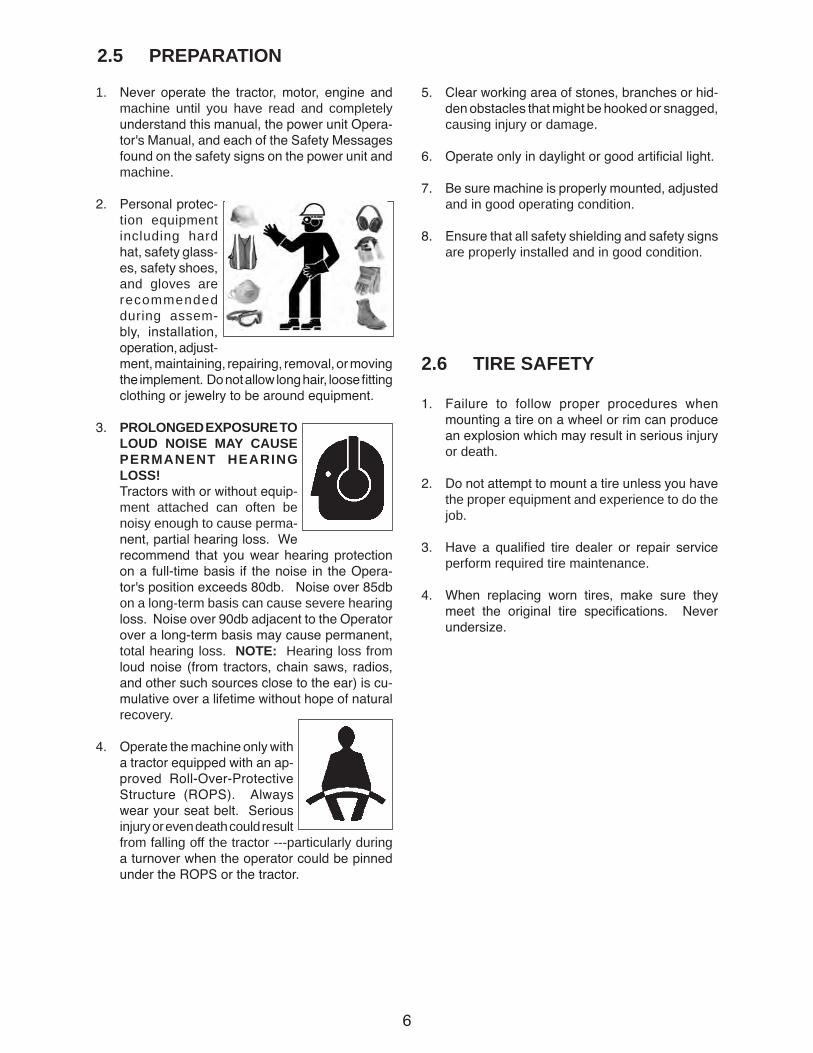
2. Personal protec-tion equipment including hard hat, safety glass-es, safety shoes, and gloves are recommended during assem-bly, installation, operation, adjust-ment, maintaining, repairing, removal, or moving the implement. Do not allow long hair, loose fitting clothing or jewelry to be around equipment.
3. PROLONGED EXPOSURE TO LOUD NOISE MAY CAUSE PERMANENT HEARING LOSS!
Tractors with or without equip-ment attached can often be noisy enough to cause perma-nent, partial hearing loss. We recommend that you wear hearing protection on a full-time basis if the noise in the Opera-tor's position exceeds 80db. Noise over 85db on a long-term basis can cause severe hearing loss. Noise over 90db adjacent to the Operator over a long-term basis may cause permanent, total hearing loss. NOTE: Hearing loss from loud noise (from tractors, chain saws, radios, and other such sources close to the ear) is cu-mulative over a lifetime without hope of natural recovery.
4. Operate the machine only with a tractor equipped with an ap-proved Roll-Over-Protective Structure (ROPS). Always wear your seat belt. Serious injury or even death could result from falling off the tractor ---particularly during a turnover when the operator could be pinned under the ROPS or the tractor.
5. Clear working area of stones, branches or hid-den obstacles that might be hooked or snagged, causing injury or damage.
6. Operate only in daylight or good artificial light.
7. Be sure machine is properly mounted, adjusted and in good operating condition.
8. Ensure that all safety shielding and safety signs are properly installed and in good condition.
2.6 TIRE SAFETY
1. Failure to follow proper procedures when mounting a tire on a wheel or rim can produce an explosion which may result in serious injury or death.
2. Do not attempt to mount a tire unless you have the proper equipment and experience to do the job.
3. Have a qualified tire dealer or repair service perform required tire maintenance.
4. When replacing worn tires, make sure they meet the original tire specifications. Never undersize.
7
2.7 MAINTENANCE SAFETY
1. Review the Operator's Manual and all safety items before working with, maintaining or oper-ating the Conveyor.
2. Place all controls in neutral or off, stop engine, remove ignition key or disable power source and wait for all moving parts to stop before servicing, adjusting, repairing or unplugging.
3. Follow good shop practices:
- Keep service area clean and dry.
- Be sure electrical outlets and tools are properly grounded.
- Use adequate light for the job at hand.
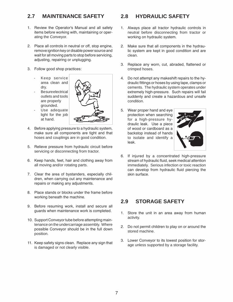
4. Before applying pressure to a hydraulic system, make sure all components are tight and that hoses and couplings are in good condition.
5. Relieve pressure from hydraulic circuit before servicing or disconnecting from tractor.
6. Keep hands, feet, hair and clothing away from all moving and/or rotating parts.
7. Clear the area of bystanders, especially chil-dren, when carrying out any maintenance and repairs or making any adjustments.
8. Place stands or blocks under the frame before working beneath the machine.
9. Before resuming work, install and secure all guards when maintenance work is completed.
10. Support Conveyor tube before attempting main-tenance on the undercarriage assembly. Where possible Conveyor should be in the full down position.
11. Keep safety signs clean. Replace any sign that is damaged or not clearly visible.
2.8 HYDRAULIC SAFETY
1. Always place all tractor hydraulic controls in neutral before disconnecting from tractor or working on hydraulic system.
2. Make sure that all components in the hydrau-lic system are kept in good condition and are clean.
3. Replace any worn, cut, abraded, flattened or crimped hoses.
4. Do not attempt any makeshift repairs to the hy-draulic fittings or hoses by using tape, clamps or cements. The hydraulic system operates under extremely high-pressure. Such repairs will fail suddenly and create a hazardous and unsafe condition.
5. Wear proper hand and eye protection when searching for a high-pressure hy-draulic leak. Use a piece of wood or cardboard as a backstop instead of hands to isolate and identify a leak.
6. If injured by a concentrated high-pressure stream of hydraulic fluid, seek medical attention immediately. Serious infection or toxic reaction can develop from hydraulic fluid piercing the skin surface.
2.9 STORAGE SAFETY
1. Store the unit in an area away from human activity.
2. Do not permit children to play on or around the stored machine.
3. Lower Conveyor to its lowest position for stor-age unless supported by a storage facility.
8
2.10 OPERATING SAFETY1. Please remember it is important that you read
and heed the safety signs on the Conveyor. Clean or replace all safety signs if they cannot be clearly read and understood. They are there for your safety, as well as the safety of others. The safe use of this machine is strictly up to you, the operator.
2. All things with moving parts are potentially haz-ardous. There is no substitute for a cautious, safe-minded operator who recognizes potential hazards and follows reasonable safety practices. The manufacturer has designed this Conveyor to be used with all its safety equipment properly attached, to minimize the chance of accidents. Study this manual to make sure you have all safety equipment attached.
3. If a safety shield or guard is removed for any reason, it must be replaced before the machine is again operated.
4. Stop the engine, place all controls in neutral, set park brake, remove ignition key and wait for all moving parts to stop before servicing, adjusting, repairing or unplugging.
5. Clear the area of bystanders, especially chil-dren, before starting.
6. Be familiar with machine hazard area. If any-one enters hazard areas, shut down machine immediately. Clear the area before restarting.
7. Keep hands, feet, hair and clothing away from all moving and/or rotating parts.
8. Do not allow riders on the Conveyor or tractor when transporting.
9. Stay away from overhead obstructions and power lines during operation and transporting. Electrocution can occur without direct contact.
10. Do not operate machine when any guards are removed.
11. Lower Conveyor to its lowest position before moving or transporting or when not in use.
12. Close valve in hydraulic line when machine positioned or before transporting.
13. Be sure that conveyor is empty before raising or lowering.
IMPORTANTBefore raising or placement of Conveyor be sure that ground is reasonably level. Conveyor could topple if ground is too un-even damaging equipment and/or causing personal injury.
2.11 PLACEMENT SAFETY1. Move only with power pack when positioning.
Never move by hand.
2. Stay away from overhead power lines when moving Conveyor. Electrocution can occur without direct contact.
3. Keep Conveyor as low as possible.
4. Chock Conveyor wheels front and rear before operating.
5. Locate Conveyor to provide ample space for trucks to unload.
6. Keep Conveyor as low as possible when mov-ing. Raise only when it is next to storage facil-ity.
7. Be familiar with the machine hazard area. If anyone enters hazard area, shut down machine immediately. Clear the area before restarting.
8. Operate the Conveyor on level ground free of debris. If ground is uneven, anchor the Con-veyor to prevent tipping or upending.
IMPORTANTWhen releasing Conveyor from the towing vehicle, test the intake end for downward weight. Do not raise the intake end above drawbar height. When the intake end is el-evated too high with machine in raised posi-tion, the balance of weight quickly transfers to the discharge end, causing the machine to upend.

9
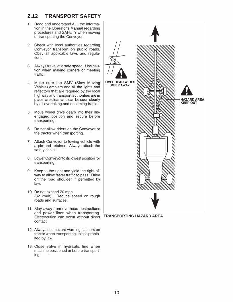
WORKPLACE HAZARD AREA
10
2.12 TRANSPORT SAFETY1. Read and understand ALL the informa-
tion in the Operator's Manual regarding procedures and SAFETY when moving or transporting the Conveyor.
2. Check with local authorities regarding Conveyor transport on public roads. Obey all applicable laws and regula-tions.
3. Always travel at a safe speed. Use cau-tion when making corners or meeting traffic.
4. Make sure the SMV (Slow Moving Vehicle) emblem and all the lights and reflectors that are required by the local highway and transport authorities are in place, are clean and can be seen clearly by all overtaking and oncoming traffic.
5. Move wheel drive gears into their dis-engaged position and secure before transporting.
6. Do not allow riders on the Conveyor or the tractor when transporting.
7. Attach Conveyor to towing vehicle with a pin and retainer. Always attach the safety chain.
8. Lower Conveyor to its lowest position for transporting.
9. Keep to the right and yield the right-of-way to allow faster traffic to pass. Drive on the road shoulder, if permitted by law.
10. Do not exceed 20 mph (32 km/h). Reduce speed on rough
roads and surfaces.
11. Stay away from overhead obstructions and power lines when transporting. Electrocution can occur without direct contact.
12. Always use hazard warning flashers on tractor when transporting unless prohib-ited by law.
13. Close valve in hydraulic line when machine positioned or before transport-ing.
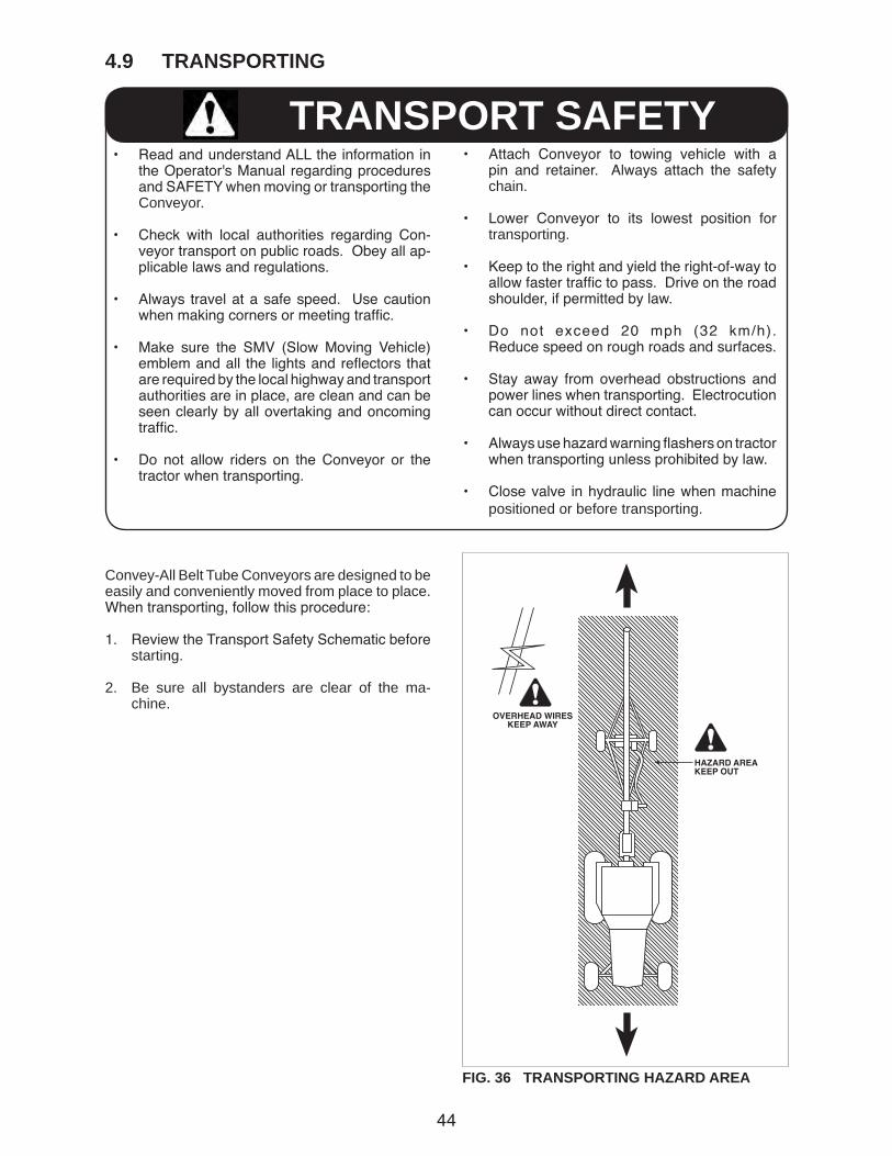
TRANSPORTING HAZARD AREA

11
2.13 REFUELLING SAFETY
1. Handle fuel with care. It is highly flammable.
2. Allow engine to cool for 5 minutes before refu-elling. Clean up spilled fuel before restarting engine.
3. Do not refuel the machine while smoking or when near open flame or sparks.
4. Fill fuel tank outdoors.
5. Prevent fires by keeping machine clean of ac-cumulated trash, grease and debris.
2.14 BATTERY SAFETY
1. Keep all sparks and flames away from batteries, as gas given off by electrolyte is explosive.
2. Avoid contact with battery electrolyte: wash off any spilled electrolyte immediately.
3. Wear safety glasses when working near batter-ies.
4. Do not tip batteries more than 45° to avoid electrolyte loss.
5. To avoid injury from spark or short circuit, dis-connect battery ground cable before servicing any part of the electrical system.
12
2.15 GAS MOTOR SAFETY
BEFORE STARTING ENGINE, READAND UNDERSTAND THE OPERATING AND MAINTENANCE INSTRUCTIONSTHAT CAME WITH YOUR ENGINE.
WARNING: DO NOT
1. DO NOT run engine in an enclosed area. Exhaust gases contain carbon monoxide, an odourless and deadly poison.
2. DO NOT place hands or feet near moving or rotating parts.
3. DO NOT store, spill, or use gasoline near an open flame, or devices such as a stove, furnace, or water heater which use a pilot light or devices which can create a spark.
4. DO NOT refuel indoors where area is not well ventilated. Outdoor refuelling is preferred.
5. DO NOT refuel while engine is running. Allow engine to cool for 5 minutes before refuelling. Store fuel in approved safety containers.
6. DO NOT remove fuel tank cap while engine is running.
7. DO NOT operate engine if gasoline is spilled. Move machine away from the spill and avoid creating any ignition until gasoline has evapo-rated.
8. DO NOT smoke while filling fuel tank.
9. DO NOT choke carburator to stop engine. Whenever possible, gradually reduce engine speed before stopping.
10. DO NOT run engine above rated speeds. This may result in injury.
11. DO NOT tamper with governor springs, gover-nor links or other parts which may increase the governed speed.
12. DO NOT tamper with the engine speed selected by the original equipment manufacturer.
13. DO NOT check for spark with spark plug or spark plug wire removed.
14. DO NOT crank engine with spark plug removed. If engine is flooded, crank until engine starts.
15. DO NOT strike flywheel with a hard object or metal tool as this may cause flywheel to shat-ter in operation. Use proper tools to service engine.
16. DO NOT operate engine without a muffler. Inspect periodically and replace, if necessary. If engine is equipped with a muffler deflector, inspect periodically and replace, if necessary with correct deflector.
17. DO NOT operate engine with an accumulation of grass, leaves, dirt or other combustible ma-terials in the muffler area.
18. DO NOT use this engine on any forest covered, brush covered, or grass covered unimproved land unless a spark arrester is installed on the muffler. The arrester must be maintained in effective working order by the operator. In the state of California the above is required by law (Section 4442 of the California Public Re-sources Code). Other states may have similar laws. Federal laws apply on federal land.
19. DO NOT touch hot muffler, cylinder or fins be-cause contact may cause burns.
20. DO NOT run engine with air cleaner or air cleaner cover removed.
WARNING: DO
1. ALWAYS DO remove the wire from the spark plug when servicing the engine or equipment to prevent accidental starting. Disconnect the negative wire from the battery terminal if equipped wit a 12 volt starting system.
2. DO keep cylinder fins and governor parts free of grass and other debris which can affect engine speed.
3. DO examine muffler periodically to be sure it is functioning effectively. A worn or leaking muffler should be repaired or replaced as necessary.
4. DO use fresh gasoline. Stale fuel can gum carburator and cause leakage.
5. DO check fuel lines and fittings frequently for cracks or leaks. Replace if necessary.

13
2.16 SIGN-OFF FORMConvey-All Belt Tube Conveyor follows the general Safety Standards specified by the American Society of Agricultural and Biological Engineers (ASABE) and the Occupational Safety and Health Administration (OSHA). Anyone who will be operating and/or maintaining the belt tube conveyor must read and clearly understand ALL Safety, Operating and Maintenance information presented in this manual.
Do not operate or allow anyone else to operate this equipment until such information has been reviewed. Annually review this information before the season start-up.
Make these periodic reviews of SAFETY and OPERATION a standard practice for all of your equipment. We feel that an untrained operator is unqualified to operate this machine.
A sign-off sheet is provided for your record keeping to show that all personnel who will be working with the equipment have read and understand the information in the Operator’s Manual and have been instructed in the operation of the equipment.
DATE EMPLOYEES SIGNATURE EMPLOYERS SIGNATURE
SIGN-OFF FORM

14
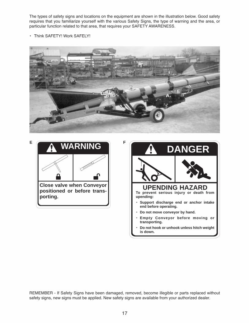
3 SAFETY SIGN LOCATIONSThe types of safety signs and locations on the equipment are shown in the illustration below. Good safety requires that you familiarize yourself with the various Safety Signs, the type of warning and the area, or particular function related to that area, that requires your SAFETY AWARENESS.
• Think SAFETY! Work SAFELY!
REMEMBER - If Safety Signs have been damaged, removed, become illegible or parts replaced without safety signs, new signs must be applied. New safety signs are available from your authorized dealer.
A WARNING
ROTATING PART HAZARDTo prevent serious injury or death from rotating parts:• Place all controls in neutral or off, stop
engine or motor, remove ignition key or disable power source and wait for all moving parts to stop before servicing, adjusting, repairing or unplugging.
• Install and secure all guards before operating.
• Do not operate with rotating parts exposed.
AH
FDG
EB

15
The types of safety signs and locations on the equipment are shown in the illustration below. Good safety requires that you familiarize yourself with the various Safety Signs, the type of warning and the area, or particular function related to that area, that requires your SAFETY AWARENESS.
• Think SAFETY! Work SAFELY!
REMEMBER - If Safety Signs have been damaged, removed, become illegible or parts replaced without safety signs, new signs must be applied. New safety signs are available from your authorized dealer.
B
CAUTION• Read and understand Opera-
tor's Manual before operating. Train operators annually.
• Keep all safety shields and devices in place and in good working order.
• Makecertaineveryone isclearbeforeoperatingor moving the machine. Keep children, visitors and untrained people away.
• Keephands,feet,hairandclothingawayfromallmoving parts.
• Shutoffanddisablepowersourcebeforeadjust-ing, repairing or cleaning.
• Disconnect power before resetting motor over-load.
• Besureelectricmotorsaregrounded.
• Empty Conveyor before moving to prevent up-ending.
• LowerConveyortoitsfullydownpositionbeforemoving or transporting. Use a tractor to move and transport.
• LowerConveyorwellbelowlevelofpowerlinesbefore moving or transporting. Electrocution can occur without direct contact.
• Keepawayfromintake.Keepothersaway.
AC

16
D
REMEMBER - If Safety Signs have been damaged, removed, become illegible or parts replaced without safety signs, new signs must be applied. New safety signs are available from your authorized dealer.
C
The types of safety signs and locations on the equipment are shown in the illustration below. Good safety requires that you familiarize yourself with the various Safety Signs, the type of warning and the area, or particular function related to that area, that requires your SAFETY AWARENESS.
• Think SAFETY! Work SAFELY!
DANGER
ELECTROCUTION HAZARDSTAY AWAY FROM POWER LINES
To prevent serious injury or death from electrocution:• Stay well away from power lines. Electro-
cution can occur without direct contact.• Lower Conveyor well below level of power
line before moving or transporting.
WARNING
HIGH-PRESSURE FLUID HAZARDTo prevent serious injury or death:
• Relieve pressure on system beforerepairing or adjusting.
• Wearproperhandandeyeprotectionwhen searching for leaks. Use wood or card board instead of hands.
• Keep all hydraulic components ingoodrepairandallfittingstight.
C
A
17
REMEMBER - If Safety Signs have been damaged, removed, become illegible or parts replaced without safety signs, new signs must be applied. New safety signs are available from your authorized dealer.
E F
The types of safety signs and locations on the equipment are shown in the illustration below. Good safety requires that you familiarize yourself with the various Safety Signs, the type of warning and the area, or particular function related to that area, that requires your SAFETY AWARENESS.
• Think SAFETY! Work SAFELY!
Close valve when Conveyor positioned or before trans-porting.
WARNING DANGER
UPENDING HAZARDTo prevent serious injury or death from upending:• Support discharge end or anchor intake
end before operating.• Do not move conveyor by hand.• Empty Conveyor before moving or
transporting.• Do not hook or unhook unless hitch weight
is down.
BD GE
AE
F
18
G
REMEMBER - If Safety Signs have been damaged, removed, become illegible or parts replaced without safety signs, new signs must be applied. New safety signs are available from your authorized dealer.
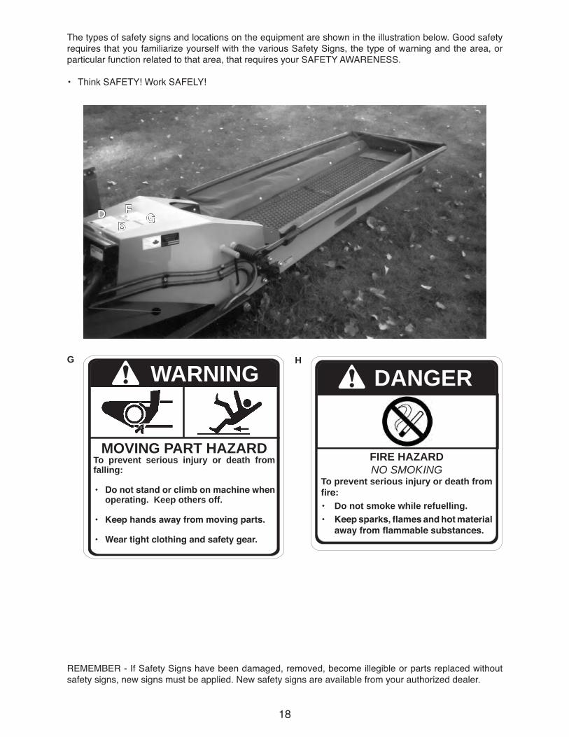
The types of safety signs and locations on the equipment are shown in the illustration below. Good safety requires that you familiarize yourself with the various Safety Signs, the type of warning and the area, or particular function related to that area, that requires your SAFETY AWARENESS.
• Think SAFETY! Work SAFELY!
MOVING PART HAZARDTo prevent serious injury or death from falling:
• Donotstandorclimbonmachinewhenoperating. Keep others off.
• Keephandsawayfrommovingparts.
• Weartightclothingandsafetygear.
WARNINGH
DANGER
FIRE HAZARDNO SMOKING
To prevent serious injury or death from fire:• Do not smoke while refuelling.• Keepsparks,flamesandhotmaterial
awayfromflammablesubstances.
BD G
F
19
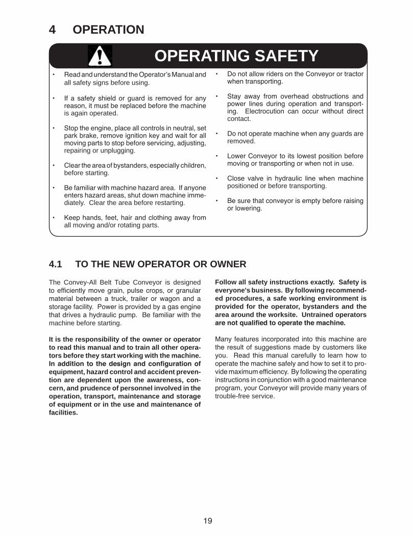
4 OPERATION
• Read and understand the Operator’s Manual and all safety signs before using.
• If a safety shield or guard is removed for any reason, it must be replaced before the machine is again operated.
• Stop the engine, place all controls in neutral, set park brake, remove ignition key and wait for all moving parts to stop before servicing, adjusting, repairing or unplugging.
• Clear the area of bystanders, especially children, before starting.
• Be familiar with machine hazard area. If anyone enters hazard areas, shut down machine imme-diately. Clear the area before restarting.
• Keep hands, feet, hair and clothing away from all moving and/or rotating parts.
OPERATING SAFETY
4.1 TO THE NEW OPERATOR OR OWNER
The Convey-All Belt Tube Conveyor is designed to efficiently move grain, pulse crops, or granular material between a truck, trailer or wagon and a storage facility. Power is provided by a gas engine that drives a hydraulic pump. Be familiar with the machine before starting.
It is the responsibility of the owner or operator to read this manual and to train all other opera-tors before they start working with the machine. Inaddition to thedesignandconfigurationofequipment, hazard control and accident preven-tion are dependent upon the awareness, con-cern, and prudence of personnel involved in the operation, transport, maintenance and storage of equipment or in the use and maintenance of facilities.
Follow all safety instructions exactly. Safety is everyone's business. By following recommend-ed procedures, a safe working environment is provided for the operator, bystanders and the area around the worksite. Untrained operators arenotqualifiedtooperatethemachine.
Many features incorporated into this machine are the result of suggestions made by customers like you. Read this manual carefully to learn how to operate the machine safely and how to set it to pro-vide maximum efficiency. By following the operating instructions in conjunction with a good maintenance program, your Conveyor will provide many years of trouble-free service.
• Do not allow riders on the Conveyor or tractor when transporting.
• Stay away from overhead obstructions and power lines during operation and transport-ing. Electrocution can occur without direct contact.
• Do not operate machine when any guards are removed.
• Lower Conveyor to its lowest position before moving or transporting or when not in use.
• Close valve in hydraulic line when machine positioned or before transporting.
• Be sure that conveyor is empty before raising or lowering.
20
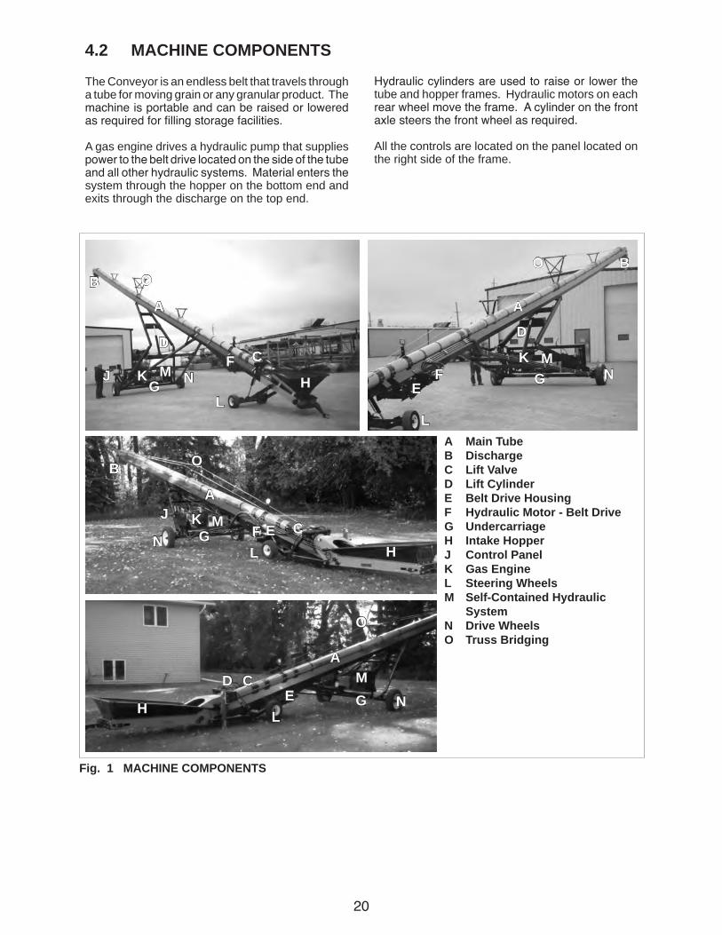
4.2 MACHINE COMPONENTS
The Conveyor is an endless belt that travels through a tube for moving grain or any granular product. The machine is portable and can be raised or lowered as required for filling storage facilities.
A gas engine drives a hydraulic pump that supplies power to the belt drive located on the side of the tube and all other hydraulic systems. Material enters the system through the hopper on the bottom end and exits through the discharge on the top end.
A Main TubeB DischargeC Lift ValveD Lift CylinderE Belt Drive HousingF Hydraulic Motor - Belt DriveG UndercarriageH Intake HopperJ Control PanelK Gas EngineL Steering WheelsM Self-Contained Hydraulic SystemN Drive WheelsO Truss Bridging
Hydraulic cylinders are used to raise or lower the tube and hopper frames. Hydraulic motors on each rear wheel move the frame. A cylinder on the front axle steers the front wheel as required.
All the controls are located on the panel located on the right side of the frame.
Fig. 1 MACHINE COMPONENTS
E
E
E
A A
A
A
BB
B
G G
G
G
J
J
J
DDD
D
C
C
C
C
H
H
H
KK
K
FF
F
OO
O
O
MM
M
M
LL
L
L
N
N
N
N

21
4.3 MACHINE BREAK-IN 4.4 PRE-OPERATION CHECKLIST
IMPORTANTAnchoring and/or support of Conveyor during operation is necessary. When lower half of Conveyor empties of mate-rial, the weight balance transfers to the upper end of the machine, which can cause upending.
Although there are no operational restrictions on the Conveyor when used for the first time, it is rec-ommended that the following mechanical items be checked:
A. Before starting work: 1. Read the Conveyor and engine Operator's
Manuals.
2. Run the unit for half an hour to seat the belt-ing and flashing around the intake hopper. It is normal for rubber from the flashing to be expelled out the discharge and form a pattern on the belt.
B. After operating or transporting for 1/2 hour:
1. Re-torque all the wheel bolts fasteners and hardware.
2. Check the conveying belt tension and align-ment. Tension or align as required.
3. During the conveyors first few minutes of operation, check belt alignment to ensure preset alignment and tension does not vary under loaded conditions.
4. Check the flashing seal on the input hop-per. If any grain comes out of the hopper around the flashing, stop, loosen flashing mounting screws and adjust. Retighten anchor screws and try again. Repeat until no grain is lost.
5. Check the condition of all hydraulic lines, hoses, fittings and couplers for damage or leaks. Tighten leaking fittings and repair or replace any damaged components.
6. Check the condition of all electrical lines, cords and connections. Repair or replace any damaged system or component.
7. Check that all guards are installed and working as intended.
C. After operating for 5 hours and 10 hours: 1. Repeat items 1 through 5 above.
2. After 10 hours, change gas engine oil (gas engine model only).
3. Then go to the normal servicing and main-tenance schedule as defined in the Main-tenance Section.
Efficient and safe operation of the Conveyor re-quires that each operator reads and understands the operating procedures and all related safety precautions outlined in this section. A pre-operation checklist is provided for the operator. It is important for both the personal safety and maintaining the good mechanical condition of the Conveyor that this checklist is followed.
Before operating the Conveyor and each time there-after, the following areas should be checked off:
1. Service the machine per the schedule outlined in Section 5 Service and Maintenance.
2. Check that all guards are installed, secured and functioning as intended. Do not operate with missing or damaged shields.
3. Check worksite. Clean up working area to pre-vent slipping or tripping.
4. Check the conveying belt tension and align-ment. Tension or align as required.
5. Check that conveying belt is not frayed or damaged and that it is properly adjusted and aligned.
6. Be sure Conveyor wheels are chocked.
7. Check that discharge and intake areas are free of obstructions.
22
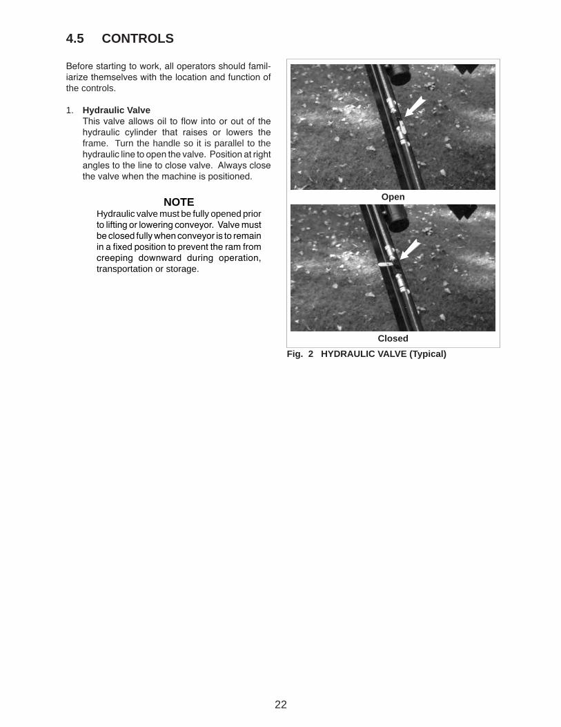
NOTEHydraulic valve must be fully opened prior to lifting or lowering conveyor. Valve must be closed fully when conveyor is to remain in a fixed position to prevent the ram from creeping downward during operation, transportation or storage.
4.5 CONTROLS
Before starting to work, all operators should famil-iarize themselves with the location and function of the controls.
1. Hydraulic Valve This valve allows oil to flow into or out of the
hydraulic cylinder that raises or lowers the frame. Turn the handle so it is parallel to the hydraulic line to open the valve. Position at right angles to the line to close valve. Always close the valve when the machine is positioned.
Fig. 2 HYDRAULIC VALVE (Typical)
Open
Closed
23
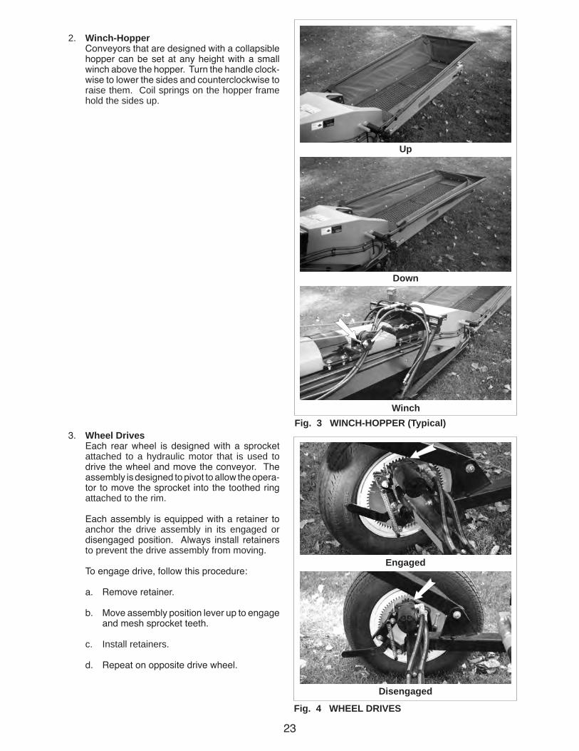
Fig. 3 WINCH-HOPPER (Typical)
Up
Down
2. Winch-Hopper Conveyors that are designed with a collapsible
hopper can be set at any height with a small winch above the hopper. Turn the handle clock-wise to lower the sides and counterclockwise to raise them. Coil springs on the hopper frame hold the sides up.
3. Wheel Drives Each rear wheel is designed with a sprocket
attached to a hydraulic motor that is used to drive the wheel and move the conveyor. The assembly is designed to pivot to allow the opera-tor to move the sprocket into the toothed ring attached to the rim.
Each assembly is equipped with a retainer to anchor the drive assembly in its engaged or disengaged position. Always install retainers to prevent the drive assembly from moving.
To engage drive, follow this procedure:
a. Remove retainer.
b. Move assembly position lever up to engage and mesh sprocket teeth.
c. Install retainers.
d. Repeat on opposite drive wheel.
Winch
Fig. 4 WHEEL DRIVES
Engaged
Disengaged

24
d
c
4. Gas Engine A gas engine is used on models up to 45 feet in
length. Read the engine manufacturers opera-tor's manual before starting for more detailed instructions.
a. Ignition Switch: This key operated switch controls the elec-
tric power to the engine.
OFF - Turn the key fully counterclockwise to stop the fuel flow and turn the engine off.
RUN - Turn clockwise on detent to the run position. This is the position where the engine will continue to run.
START - Turn fully clockwise to the last spring-loaded detent position to engage the starter solenoid and start the engine. Release the key when the engine starts and it will return to the RUN position.
b. Choke: This lever controls the position of the choke.
Push the lever to the left in to close the choke for starting when the engine is cold. Move the lever to the right to open the choke as the engine warms. Always move the lever fully to the right when operating the machine.
c. Throttle: This lever controls the throttle position on
the engine through a mechanical linkage on the carburator. Move the lever to the right to increase engine RPM and to the left to decrease.
d. Low Oil Pressure Light: This light monitors the engine oil pressure.
It illuminates when the engine oil pressure drops below a pre-set value set at the fac-tory to alert the operator to the low oil pres-sure condition. The light goes out when oil pressure increases above the pre-set value.
a
Fig. 5 ENGINE
b
25
Fig. 6 ENGINE CONTROLS
Engine
Instrument Panel
a
b
a
c d
e fghjklm
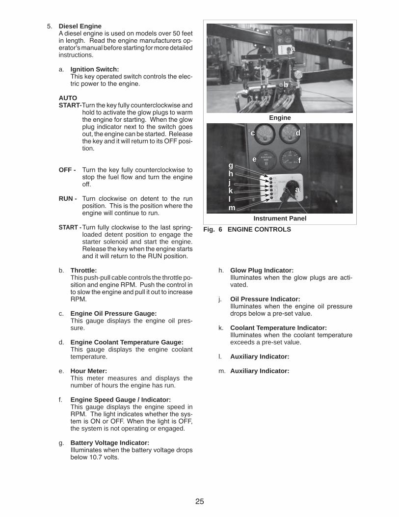
5. Diesel Engine A diesel engine is used on models over 50 feet
in length. Read the engine manufacturers op-erator's manual before starting for more detailed instructions.
a. Ignition Switch: This key operated switch controls the elec-
tric power to the engine.
AUTO START-Turn the key fully counterclockwise and
hold to activate the glow plugs to warm the engine for starting. When the glow plug indicator next to the switch goes out, the engine can be started. Release the key and it will return to its OFF posi-tion.
OFF - Turn the key fully counterclockwise to stop the fuel flow and turn the engine off.
RUN - Turn clockwise on detent to the run position. This is the position where the engine will continue to run.
START - Turn fully clockwise to the last spring-loaded detent position to engage the starter solenoid and start the engine. Release the key when the engine starts and it will return to the RUN position.
b. Throttle: This push-pull cable controls the throttle po-
sition and engine RPM. Push the control in to slow the engine and pull it out to increase RPM.
c. Engine Oil Pressure Gauge: This gauge displays the engine oil pres-
sure.
d. Engine Coolant Temperature Gauge: This gauge displays the engine coolant
temperature.
e. Hour Meter: This meter measures and displays the
number of hours the engine has run.
f. Engine Speed Gauge / Indicator: This gauge displays the engine speed in
RPM. The light indicates whether the sys-tem is ON or OFF. When the light is OFF, the system is not operating or engaged.
g. Battery Voltage Indicator: Illuminates when the battery voltage drops
below 10.7 volts.
h. Glow Plug Indicator: Illuminates when the glow plugs are acti-
vated.
j. Oil Pressure Indicator: Illuminates when the engine oil pressure
drops below a pre-set value.
k. Coolant Temperature Indicator: Illuminates when the coolant temperature
exceeds a pre-set value.
l. Auxiliary Indicator:
m. Auxiliary Indicator:

26
6. Hydraulic Controls.
a. Machine Movement This 4-position spring-loaded-to-neutral-
center joy stick controls the movement of the conveyor.
• Move the lever to the left (rearward) and hold to move the conveyor rearward. Release lever and conveyor will stop moving.
• Move the lever to the right (forward) and hold to move the conveyor forward. Release lever and conveyor will stop moving.
• Move the lever up and hold to turn the steering wheels so the machine will turn left.
• Move the lever down and hold to turn the steering wheels to the machine will turn right.
b. Frame Height This 3-position spring-loaded-to-neutral-
center lever controls the height or position of the main frame. Push the lever forward and hold to raise the frame. Pull and hold to lower the frame. Release the lever and the frame will stop moving.
c. Hopper Height This 3-position spring-loaded-to-neutral-
center lever controls the height or position of the hopper. Push the lever forward and hold to raise the hopper frame. Pull and hold to lower the hopper frame. Release the lever and the hopper frame will stop moving.
d. Belt Drive This 2-position lever sets and controls the
flow of hydraulic oil to the belt drive motor. Pull on the lever to run the belt and push it in to stop.
NOTEWatch the wheels when holding the lever. Turn the wheels only as much as required.
NOTEAs the frame is raised, the hop-per frame is also automatically raised to keep it from digging into the ground as the tube an-gle changes.
Fig. 7 ENGINE CONTROLS
Gas Engine
Diesel Engine
a
b c
d
e
f
a
b ce
f
d
e. Hydraulic Pressure Gauge This gauge displays the hydraulic pressure
in the machine moving and lifting circuits.
f. Belt Drive Pressure Gauge This gauge displays the hydraulic pressure
in the belt drive circuit.

27
Fig. 8 ELECTRICAL CONTROLS
Gas Engine
Diesel Engine
b
ba
a
7. Electrical Controls.
a. Lights Move the switch up to turn the lights ON and
down to turn the lights OFF.
b. Discharge Hood Position This 3-position spring-loaded-to-off-center
switch controls and sets the position of the discharge hood. Move the switch up and hold to retract the electric actuator on the top and raise the angle of the discharge hood. Move the switch down and hold to lower the angle of the discharge hood. Release the switch and the discharge hood will stay in its current position.
28
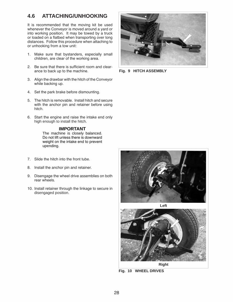
4.6 ATTACHING/UNHOOKINGIt is recommended that the moving kit be used whenever the Conveyor is moved around a yard or into working position. It may be towed by a truck or loaded on a flatbed when transporting over long distances. Follow this procedure when attaching to or unhooking from a tow unit:
1. Make sure that bystanders, especially small children, are clear of the working area.
2. Be sure that there is sufficient room and clear-ance to back up to the machine.
3. Align the drawbar with the hitch of the Conveyor while backing up.
4. Set the park brake before dismounting.
5. The hitch is removable. Install hitch and secure with the anchor pin and retainer before using hitch.
6. Start the engine and raise the intake end only high enough to install the hitch.
7. Slide the hitch into the front tube.
8. Install the anchor pin and retainer.
9. Disengage the wheel drive assemblies on both rear wheels.
10. Install retainer through the linkage to secure in disengaged position.
Fig. 9 HITCH ASSEMBLY
IMPORTANTThe machine is closely balanced. Do not lift unless there is downward weight on the intake end to prevent upending.
Fig. 10 WHEEL DRIVES
Left
Right
29
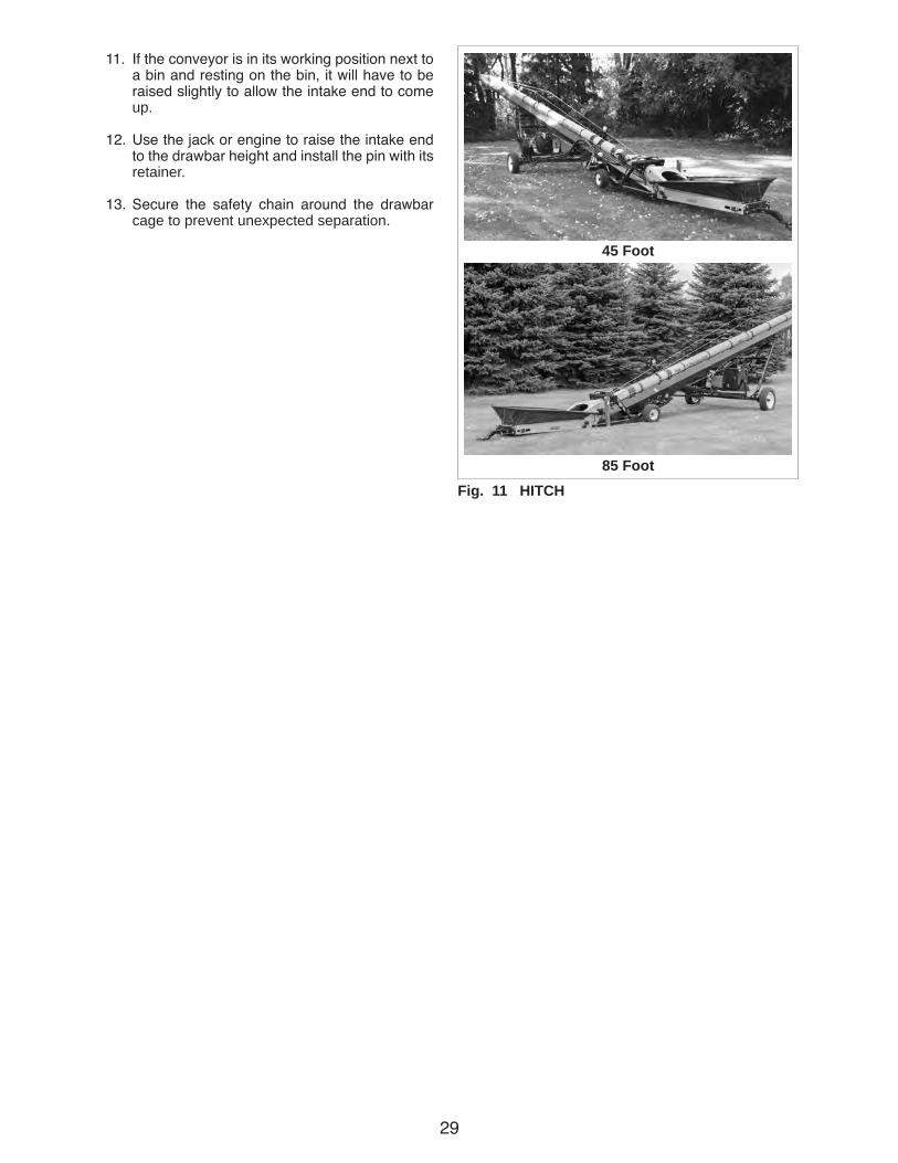
11. If the conveyor is in its working position next to a bin and resting on the bin, it will have to be raised slightly to allow the intake end to come up.
12. Use the jack or engine to raise the intake end to the drawbar height and install the pin with its retainer.
13. Secure the safety chain around the drawbar cage to prevent unexpected separation.
Fig. 11 HITCH
45 Foot
85 Foot

30
14. Raise the jack, unpin anchor bracket, rotate 90° and secure with anchor pin and retainer.
15. Remove chocks from machine wheels.
16. Connect the wiring harness across the hitch. Secure with clips, ties or tape. Provide slack for turning.
17. If conveyor is next to a storage facility, move forward until the discharge end clears the facil-ity. Then lower machine to its lowest position before moving.
18. Raise the steering wheel assembly into its high-est position and secure with transport lock and retainer.
19. Move to new location.
20. Refer to Section 4.11 Transporting before mov-ing the machine.
21. Reverse the above procedure when unhook-ing.
Fig. 12 ATTACHED
Jack
Stowed
Fig. 13 STEERING WHEEL TRANSPORT LOCK
Lock
Retainer Installed
DANGER
ELECTROCUTION HAZARDSTAY AWAY FROM POWER LINES
To prevent serious injury or death from electrocution:• Stay well away from power lines. Electro-
cution can occur without direct contact.• Lower Conveyor well below level of power
line before moving or transporting.36-1700-0002

31
4.7 MACHINE PLACEMENTFollow this procedure when placing the Conveyor into its working position:
1. Clear the area of bystanders, especially small children, before starting.
2. Be sure there is enough clearance from over-head obstructions and power lines or other equipment to move the machine into its working position.
3. Attach the Conveyor to the tow unit (See Section 4.6).
4. Back the machine up to the storage facility while it is in its lowered configuration.
5. Set the park brake on the tow unit before dis-mounting.
6. Unhook tow unit and drive it away.
7. Engage the drive wheels.
Fig. 14 MACHINE (Typical)
45 Foot
85 Foot
Fig. 15 DRIVE WHEELS
Disengaged
Engaged

32
Fig. 16 RAISING (Typical)
Low
Medium
High
8. Start the engine and use the hydraulics to slowly raise the machine into position. Stay away from power lines.
9. Slowly back the machine until the discharge is over the opening in the storage facility.
10. Use the hydraulics or winch to slowly lower the discharge end of the machine until it is just above the storage facility.
11. Place chocks in the front and rear of each wheel.
DANGER
ELECTROCUTION HAZARDSTAY AWAY FROM POWER LINES
To prevent serious injury or death from electrocution:• Stay well away from power lines. Electro-
cution can occur without direct contact.• Lower Conveyor well below level of power
line before moving or transporting.36-1700-0002
33
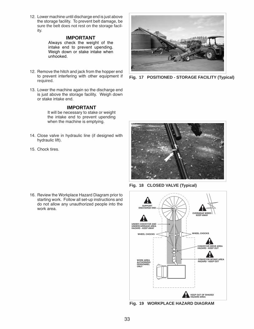
12. Lower machine until discharge end is just above the storage facility. To prevent belt damage, be sure the belt does not rest on the storage facil-ity.
12. Remove the hitch and jack from the hopper end to prevent interfering with other equipment if required.
13. Lower the machine again so the discharge end is just above the storage facility. Weigh down or stake intake end.
14. Close valve in hydraulic line (if designed with hydraulic lift).
15. Chock tires.
16. Review the Workplace Hazard Diagram prior to starting work. Follow all set-up instructions and do not allow any unauthorized people into the work area.
Fig. 17 POSITIONED - STORAGE FACILITY (Typical)
Fig. 18 CLOSED VALVE (Typical)
Fig. 19 WORKPLACE HAZARD DIAGRAM
IMPORTANTAlways check the weight of the intake end to prevent upending. Weigh down or stake intake when unhooked.
IMPORTANTIt will be necessary to stake or weight the intake end to prevent upending when the machine is emptying.
34
4.8 OPERATING
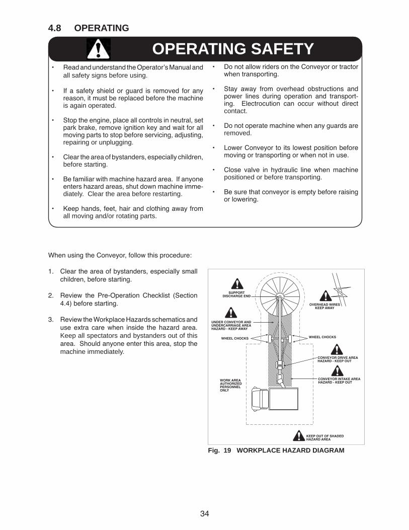
When using the Conveyor, follow this procedure:
1. Clear the area of bystanders, especially small children, before starting.
2. Review the Pre-Operation Checklist (Section 4.4) before starting.
3. Review the Workplace Hazards schematics and use extra care when inside the hazard area. Keep all spectators and bystanders out of this area. Should anyone enter this area, stop the machine immediately.
Fig. 19 WORKPLACE HAZARD DIAGRAM
• Read and understand the Operator’s Manual and all safety signs before using.
• If a safety shield or guard is removed for any reason, it must be replaced before the machine is again operated.
• Stop the engine, place all controls in neutral, set park brake, remove ignition key and wait for all moving parts to stop before servicing, adjusting, repairing or unplugging.
• Clear the area of bystanders, especially children, before starting.
• Be familiar with machine hazard area. If anyone enters hazard areas, shut down machine imme-diately. Clear the area before restarting.
• Keep hands, feet, hair and clothing away from all moving and/or rotating parts.
OPERATING SAFETY• Do not allow riders on the Conveyor or tractor
when transporting.
• Stay away from overhead obstructions and power lines during operation and transport-ing. Electrocution can occur without direct contact.
• Do not operate machine when any guards are removed.
• Lower Conveyor to its lowest position before moving or transporting or when not in use.
• Close valve in hydraulic line when machine positioned or before transporting.
• Be sure that conveyor is empty before raising or lowering.
35
4. Check that the machine is placed per Section 4.6.
5. Check that all guards are in place and working as intended.
6. Check conveying belt tension and alignment. There may be a rapid decrease in belt tension during the first few hours of operation until the belt(s) have run in. The correct operating ten-sion is the lowest tension at which the belt(s) will not slip under peak load conditions.
7. Back the truck into position for unloading.
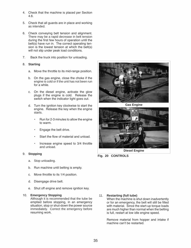
8. Starting
a. Move the throttle to its mid-range position.
b. On the gas engine, close the choke if the engine is cold or if the unit has not been run for a while.
c. On the diesel engine, activate the glow plugs if the engine is cold. Release the switch when the indicator light goes out.
d. Turn the ignition key clockwise to start the engine. Release the key when the engine starts.
• Run for 2-3 minutes to allow the engine to warm.
• Engage the belt drive.
• Start the flow of material and unload.
• Increase engine speed to 3/4 throttle and unload.
9. Stopping
a. Stop unloading.
b. Run machine until belting is empty.
c. Move throttle to its 1/4 position.
d. Disengage drive belt.
e. Shut off engine and remove ignition key.
10. Emergency Stopping Although it is recommended that the tube be
emptied before stopping, in an emergency situation, stop or shut-down the power source immediately. Correct the emergency before resuming work.
Fig. 20 CONTROLS
Gas Engine
Diesel Engine
11. Restarting (full tube) When the machine is shut down inadvertently
or for an emergency, the belt will still be filled with material. Since the start-up torque loads are much higher than normal when the belting is full, restart at low idle engine speed.
Remove material from hopper and intake if machine can't be restarted.
36
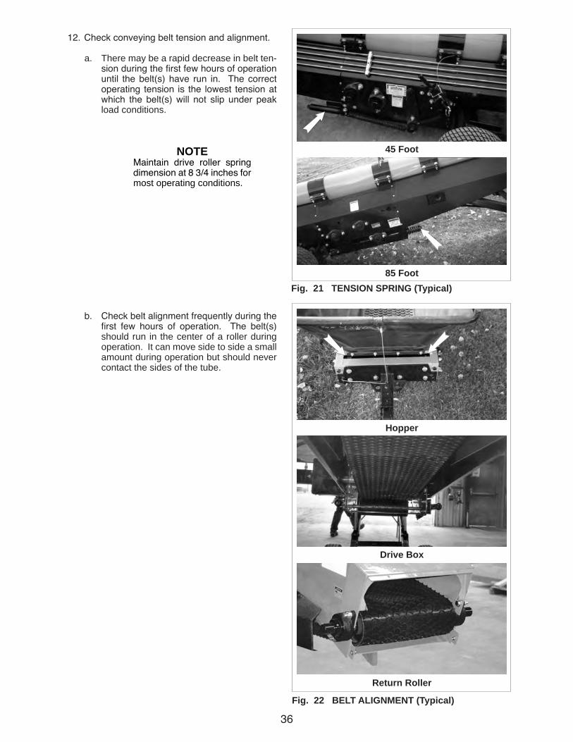
12. Check conveying belt tension and alignment.
a. There may be a rapid decrease in belt ten-sion during the first few hours of operation until the belt(s) have run in. The correct operating tension is the lowest tension at which the belt(s) will not slip under peak load conditions.
b. Check belt alignment frequently during the first few hours of operation. The belt(s) should run in the center of a roller during operation. It can move side to side a small amount during operation but should never contact the sides of the tube.
Fig. 21 TENSION SPRING (Typical)
45 Foot
85 Foot
NOTEMaintain drive roller spring dimension at 8 3/4 inches for most operating conditions.
Fig. 22 BELT ALIGNMENT (Typical)
Hopper
Drive Box
Return Roller
37
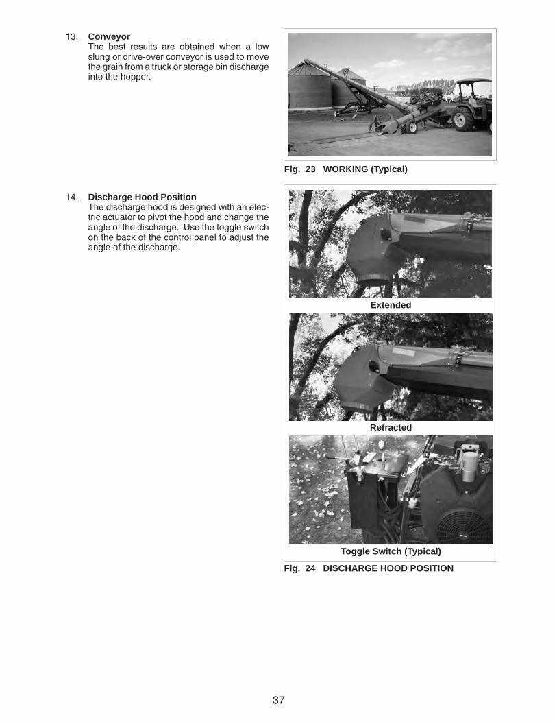
13. Conveyor The best results are obtained when a low
slung or drive-over conveyor is used to move the grain from a truck or storage bin discharge into the hopper.
14. Discharge Hood Position The discharge hood is designed with an elec-
tric actuator to pivot the hood and change the angle of the discharge. Use the toggle switch on the back of the control panel to adjust the angle of the discharge.
Fig. 24 DISCHARGE HOOD POSITION
Extended
Retracted
Toggle Switch (Typical)
Fig. 23 WORKING (Typical)
38
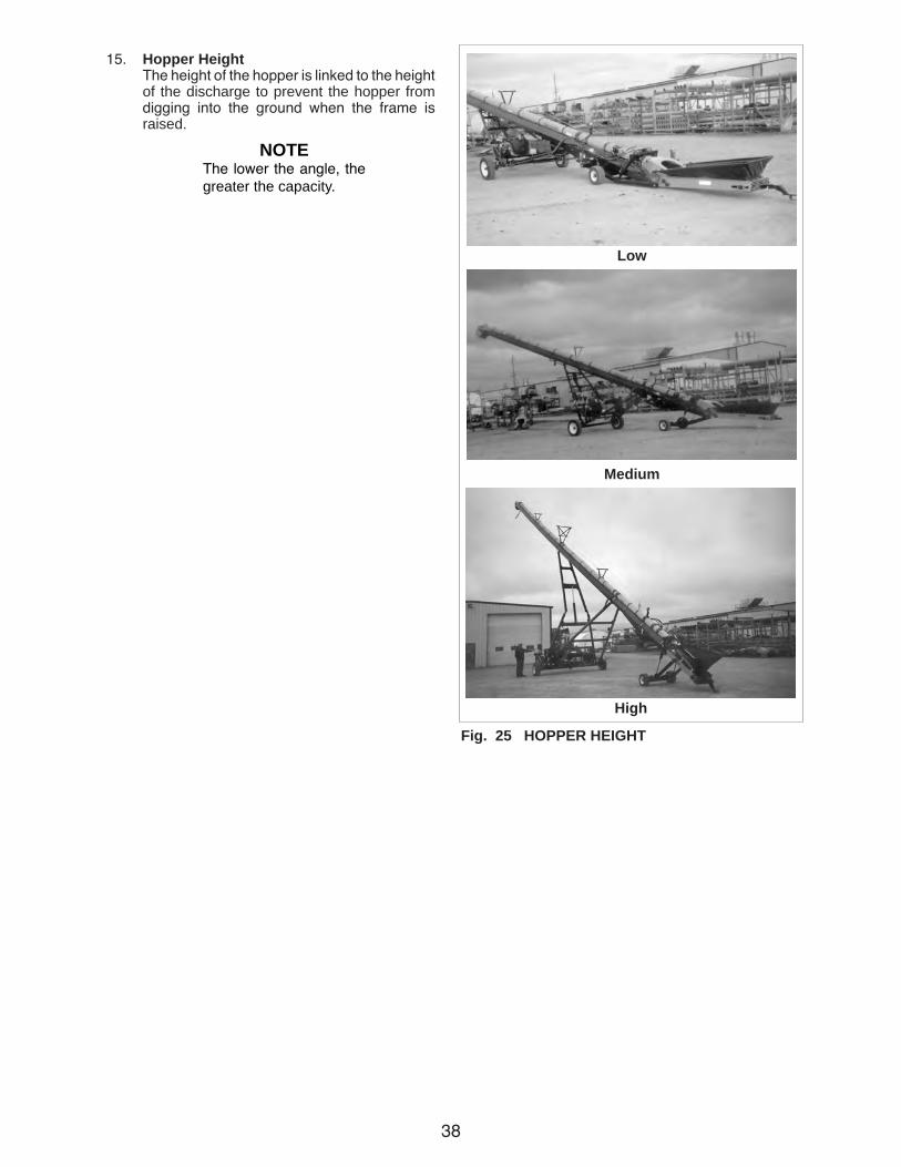
15. Hopper Height The height of the hopper is linked to the height
of the discharge to prevent the hopper from digging into the ground when the frame is raised.
NOTEThe lower the angle, the greater the capacity.
Fig. 25 HOPPER HEIGHT
Low
Medium
High
39
Fig. 26 LIGHTS
Front
Rear
Switch
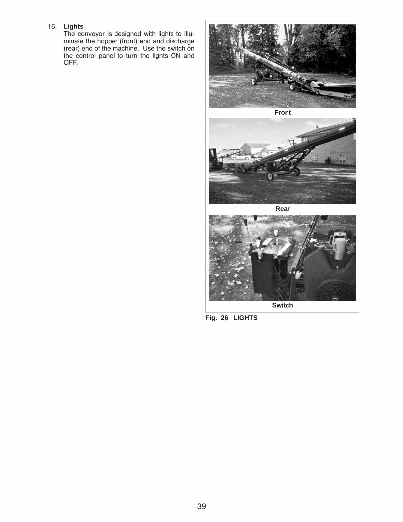
16. Lights The conveyor is designed with lights to illu-
minate the hopper (front) end and discharge (rear) end of the machine. Use the switch on the control panel to turn the lights ON and OFF.
40
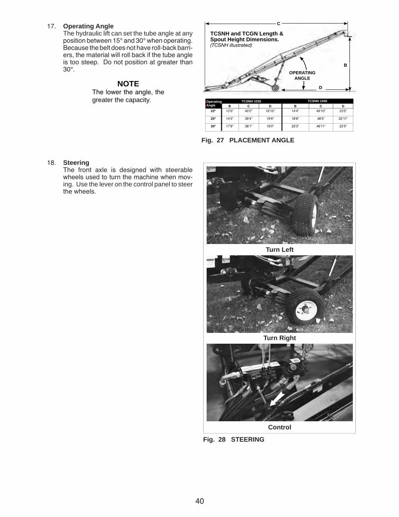
Fig. 27 PLACEMENT ANGLE
Fig. 28 STEERING
Turn Left
Turn Right
Control
17. Operating Angle The hydraulic lift can set the tube angle at any
position between 15° and 30° when operating. Because the belt does not have roll-back barri-ers, the material will roll back if the tube angle is too steep. Do not position at greater than 30°.
18. Steering The front axle is designed with steerable
wheels used to turn the machine when mov-ing. Use the lever on the control panel to steer the wheels.
NOTEThe lower the angle, the greater the capacity.
B C D B C D22º 12ʼ0” 40ʼ2” 19ʼ10” 14ʼ4” 49ʼ10” 23ʼ5”
25º 14ʼ5” 39ʼ4” 19ʼ6” 18ʼ8” 48ʼ5” 22ʼ11”
30º 17ʼ9” 38ʼ1” 19ʼ0” 22ʼ3” 46ʼ11” 22ʼ5”
Conveyors With Low Profile Hoppers
CONVEY-ALL®
D
B
C
OPERATINGANGLE
TCSNH and TCGN Length & Spout Height Dimensions. (TCSNH illustrated)
TCSNH 1035 TCSNH 1045OperatingAngle

41
Fig. 29 SPLICE (Typical)
19. Belt Speed The best results are obtained when the input
drives are set to provide a belt speed of 600 - 650 up to 700 ft/min (when empty). Diesel unit may be a bit slower. Count the number of belt revolutions per unit time to determine belt speed. Use the connector splice as a reference when counting belt revolutions.
22. Operating hints:
a. Direct the flow of material into the input hopper when moving material. Best results will be obtained when flow of in-coming materials are directed to the front (upper) area of hopper and material being dumped is centred in hopper. Keep the hopper full for maximum capacity.
b. Always listen for any unusual sounds or noises. If any are heard, stop the machine and determine the source. Correct the problem before resuming work.
c. Never allow anyone into the workplace hazard area. If anyone enters, stop im-mediately. Make them LEAVE before resuming work.
d. The upper portion of the hopper frame is spring loaded to allow the truck box to push the hopper edge down when raising the hoist.
e. Do not run the machine for long periods of time with no material on the belting. It increases the wear. Try to run only when moving material.
f. Do not move the machine by hand. Always use a power pack or tractor if needed.
Fig. 30 INPUT HOPPER (Typical)
Fig. 31 COLLAPSIBLE (Typical)

42
g. Keep intake end completely covered with material for maximum capacity.
h. The best capacity is obtained when the hopper is completely filled.
i. Use a low-slung conveyor to move grain from the bin or truck discharge into the conveyor when emptying units.
k. Each machine is designed to raise the hopper end as the discharge end is raised to prevent the hopper end frame from con-tacting the ground. In addition, the hopper can be raised and lowered independently to match the application.
Fig. 33 HOPPER HEIGHT
Raising
Higher
Independent
Fig. 32 WORKING
43
Fig. 35 FLASHING
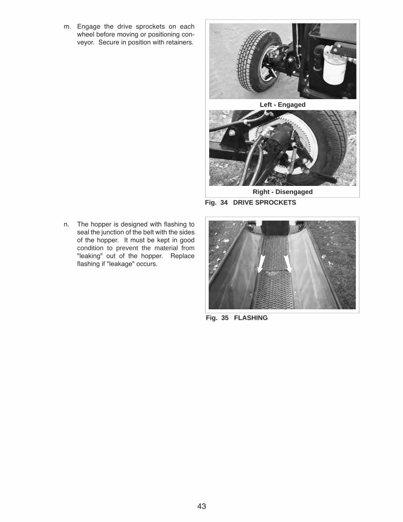
m. Engage the drive sprockets on each wheel before moving or positioning con-veyor. Secure in position with retainers.
n. The hopper is designed with flashing to seal the junction of the belt with the sides of the hopper. It must be kept in good condition to prevent the material from "leaking" out of the hopper. Replace flashing if "leakage" occurs.
Fig. 34 DRIVE SPROCKETS
Left - Engaged
Right - Disengaged
44
4.9 TRANSPORTING
Convey-All Belt Tube Conveyors are designed to be easily and conveniently moved from place to place. When transporting, follow this procedure:
1. Review the Transport Safety Schematic before starting.
2. Be sure all bystanders are clear of the ma-chine.
TRANSPORT SAFETY• Read and understand ALL the information in
the Operator's Manual regarding procedures and SAFETY when moving or transporting the Conveyor.
• Check with local authorities regarding Con-veyor transport on public roads. Obey all ap-plicable laws and regulations.
• Always travel at a safe speed. Use caution when making corners or meeting traffic.
• Make sure the SMV (Slow Moving Vehicle) emblem and all the lights and reflectors that are required by the local highway and transport authorities are in place, are clean and can be seen clearly by all overtaking and oncoming traffic.
• Do not allow riders on the Conveyor or the tractor when transporting.
• Attach Conveyor to towing vehicle with a pin and retainer. Always attach the safety chain.
• Lower Conveyor to its lowest position for transporting.
• Keep to the right and yield the right-of-way to allow faster traffic to pass. Drive on the road shoulder, if permitted by law.
• Do not exceed 20 mph (32 km/h). Reduce speed on rough roads and surfaces.
• Stay away from overhead obstructions and power lines when transporting. Electrocution can occur without direct contact.
• Always use hazard warning flashers on tractor when transporting unless prohibited by law.
• Close valve in hydraulic line when machine positioned or before transporting.
FIG. 36 TRANSPORTING HAZARD AREA
45
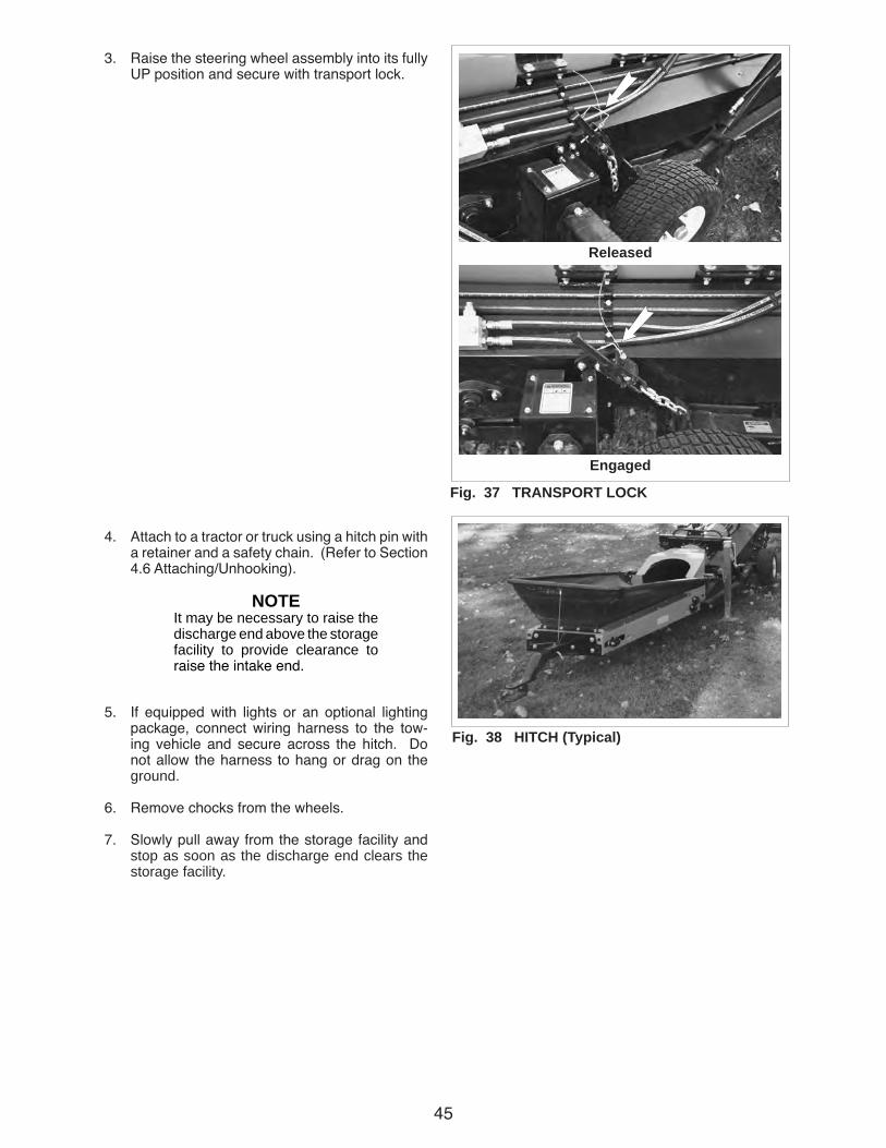
3. Raise the steering wheel assembly into its fully UP position and secure with transport lock.
4. Attach to a tractor or truck using a hitch pin with a retainer and a safety chain. (Refer to Section 4.6 Attaching/Unhooking).
5. If equipped with lights or an optional lighting package, connect wiring harness to the tow-ing vehicle and secure across the hitch. Do not allow the harness to hang or drag on the ground.
6. Remove chocks from the wheels.
7. Slowly pull away from the storage facility and stop as soon as the discharge end clears the storage facility.
NOTEIt may be necessary to raise the discharge end above the storage facility to provide clearance to raise the intake end.
Fig. 37 TRANSPORT LOCK
Fig. 38 HITCH (Typical)
Released
Engaged

46
Fig. 39 CLOSED VALVE (Typical)
8. Stop and lower the conveyor into its fully down position. Close the valve in the hydraulic line.
9. Transport only when machine is in its lowest position.
10. Stay away from overhead power lines. Electro-cution can occur without direct contact. DANGER
ELECTROCUTION HAZARDSTAY AWAY FROM POWER LINES
To prevent serious injury or death from electrocution:• Stay well away from power lines. Electro-
cution can occur without direct contact.• Lower Conveyor well below level of power
line before moving or transporting.36-1700-0002
47
11. Never go across slopes of more than 20°. It is better to go straight up or straight down.
12. Make sure the SMV (Slow Moving Vehicle) em-blem is installed when towing with a tractor. In-stall all the lights and reflectors that are required by the local highway and transport authorities are in place, are clean and can be seen clearly by all overtaking and oncoming traffic.
13. Keep to the right and yield the right-of-way to allow faster traffic to pass. Drive on the road shoulder, if permitted by law.
14. Do not allow riders on the machine or tractor.
15. During periods of limited visibility, use pilot ve-hicles or add extra lights to the machine.
16. Always use hazard flashers on the tractor when transporting unless prohibited by law.
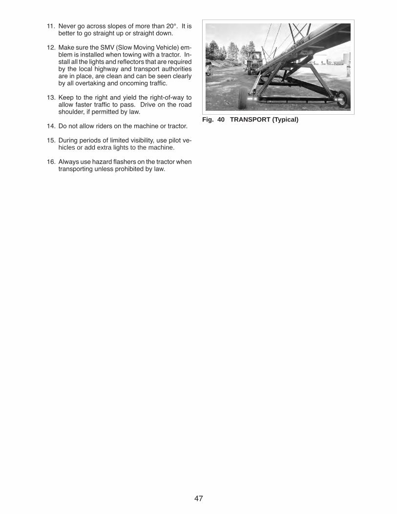
Fig. 40 TRANSPORT (Typical)

48
4.10 STORAGE
• Store the unit in an area away from human activity.
• Do not permit children to play on or around the stored machine.
• Lower Conveyor to its lowest position for stor-age unless supported by a storage facility.
STORAGE SAFETY
After the season's use, the machine should be thor-oughly inspected and prepared for storage. Repair or replace any worn or damaged components to prevent any unnecessary down time at the start of next season. To insure a long, trouble free life, this procedure should be followed when preparing the unit for storage:
1. Remove all residual material from the hopper and the tube.
2. Wash the entire machine thoroughly using a water hose or pressure washer to remove all dirt, mud, debris or residue.
3. Inspect all moving or rotating parts to see if any-thing has become entangled in them. Remove the entangled material.
4. Inspect all hydraulic hoses, fittings, lines, cou-plers and valves. Tighten any loose fittings. Replace any hose that is badly cut, nicked or abraded or is separating from the crimped end of the fitting.
5. Touch up all paint nicks and scratches to prevent rusting.
6. Select an area that is dry, level and free of de-bris.
7. If the Conveyor is not being left at a storage fa-cility, it should be placed in its lowest position.
8. Follow the procedure given in Section 4.5 when unhooking.
Fig. 42 STORAGE (Typical)
45 Foot
85 Foot
49
5 SERVICE AND MAINTENANCE
MAINTENANCE SAFETY 5.1 SERVICE5.1.1 FLUIDS AND LUBRICANTS
1. Grease: Use an SAE multipurpose high temperature
grease with extreme pressure (EP) perform-ance. Also acceptable is an SAE multipurpose lithium based grease.
2. Fuel (Gas Engine model): Use a regular unleaded automotive gasoline for
all operating conditions.
Capacity: 38 hp or 40 hp Diesel:
100 liters (25 US gal)
3. Engine Oil (Gas Engine model): Use a typical SAE 10W30 or 10W40 multi
viscosity motor oil for normal operating condi-tions (5W40 FOR 40 HP). Consult your engine manual for recommended oil in cold tempera-tures.
Capacity: 38 hp: 3.0 liters (2.9 US qt)
Capacity: 40 hp: 3.8 liters (4.0 US qt)
4. Hydraulic Oil: Use a heavy duty hydraulic oil for all applica-
tions.
Reservoir Capacity: 200 liters (48 US gal)
4. Storing Lubricants: Your machine can operate at top efficiency only
if clean lubricants are used. Use clean contain-ers to handle all lubricants. Store them in an area protected from dust, moisture and other contaminants.
5.1.2 GREASING
Use the Maintenance Checklist provided to keep arecord of all scheduled maintenance.
1. Use a hand-held grease gun for all greasing.
2. Wipe grease fitting with a clean cloth before greasing, to avoid injecting dirt and grit.
3. Replace and repair broken fittings immedi-ately.
4. If fittings will not take grease, remove and clean thoroughly. Also clean lubricant passageway. Replace fitting if necessary.
• Review the Operator's Manual and all safety items before working with, maintaining or operating the Conveyor.
• Place all controls in neutral or off, stop engine, remove ignition key or disable power source and wait for all moving parts to stop before servicing, adjusting, repairing or unplug-ging.
• Follow good shop practices:
- Keep service area clean and dry.
- Be sure electrical outlets and tools are properly grounded.
- Use adequate light for the job at hand.
• Before applying pressure to a hydraulic sys-tem, make sure all components are tight and that hoses and couplings are in good condi-tion.
• Relieve pressure from hydraulic circuit before servicing or disconnecting from tractor.
• Keep hands, feet, hair and clothing away from all moving and/or rotating parts.
• Clear the area of bystanders, especially chil-dren, when carrying out any maintenance and repairs or making any adjustments.
• Place stands or blocks under the frame before working beneath the machine.
• Before resuming work, install and secure all guards when maintenance work is com-pleted.
• Support Conveyor tube before attempting maintenance on the undercarriage assembly. Where possible Conveyor should be in the full down position.
• Keep safety signs clean. Replace any sign that is damaged or not clearly visible.

50
5.1.3 SERVICING INTERVALS
Initial Start Up Servicing: As the belt alignment is preset to run true under a condition of no load, it is important to check alignment and make adjust-ments, if required during the initial few minutes of loaded operation.
The period recommended is based on normal oper-ating conditions. Severe or unusual conditions may require more frequent lubrication or oil changes.
8 Hours or Daily
1. Check engine fluid levels.
a. Fuel level.
b. Crankcase oil level.
c. Coolant level (38 hp engine only).
Fig. 43 FLUID LEVELS
45 Foot
85 Foot
ab
a
b
c
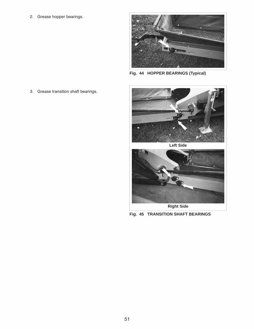
51
2. Grease hopper bearings.
3. Grease transition shaft bearings.
Fig. 44 HOPPER BEARINGS (Typical)
Fig. 45 TRANSITION SHAFT BEARINGS
Left Side
Right Side
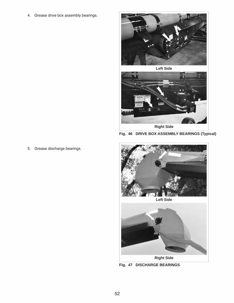
52
4. Grease drive box assembly bearings.
5. Grease discharge bearings.
Fig. 46 DRIVE BOX ASSEMBLY BEARINGS (Typical)
Left Side
Right Side
Fig. 47 DISCHARGE BEARINGS
Left Side
Right Side
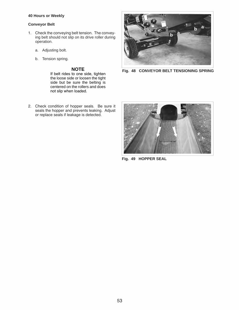
53
40 Hours or Weekly
Conveyor Belt
1. Check the conveying belt tension. The convey-ing belt should not slip on its drive roller during operation.
a. Adjusting bolt.
b. Tension spring.
2. Check condition of hopper seals. Be sure it seals the hopper and prevents leaking. Adjust or replace seals if leakage is detected.
NOTEIf belt rides to one side, tighten the loose side or loosen the tight side but be sure the belting is centered on the rollers and does not slip when loaded.
Fig. 49 HOPPER SEAL
Fig. 48 CONVEYOR BELT TENSIONING SPRING
abab

54
Drive Box
Hopper EndFig. 50 CONVEYING BELT ALIGNMENT (Typical)
3. Check alignment of the conveying belt.
Return
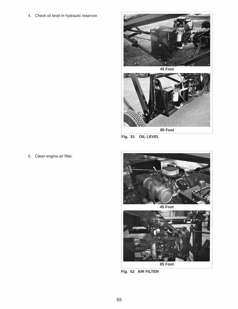
55
4. Check oil level in hydraulic reservoir.
5. Clean engine air filter.
45 Foot
85 FootFig. 51 OIL LEVEL
Fig. 52 AIR FILTER
45 Foot
85 Foot

56
100 Hours
1. Change engine oil.
a. Drain plug.
b. Dip stick.
c. Fill plug.
2. Change engine oil filter.
3. Change fuel filter.
Fig. 53 ENGINE FLUIDS
45 Foot
85 Foot
Fig. 54 FUEL FILTERS
45 Foot
85 Foot
a
c
b
2
2
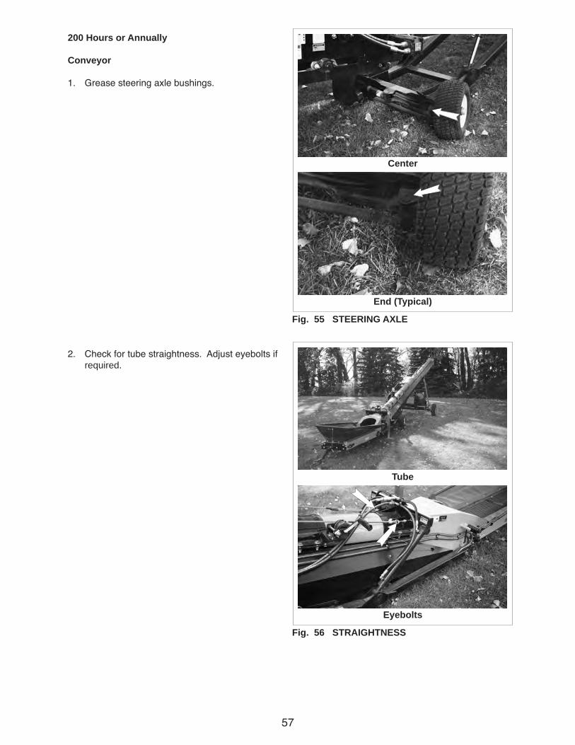
57
200 Hours or Annually
Conveyor
1. Grease steering axle bushings.
2. Check for tube straightness. Adjust eyebolts if required.
Fig. 55 STEERING AXLE
Fig. 56 STRAIGHTNESS
Center
Tube
End (Typical)
Eyebolts
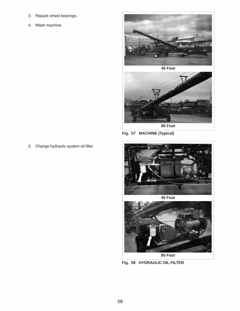
58
3. Repack wheel bearings.
4. Wash machine.
5. Change hydraulic system oil filter.
Fig. 57 MACHINE (Typical)
45 Foot
85 Foot
Fig. 58 HYDRAULIC OIL FILTER
45 Foot
85 Foot
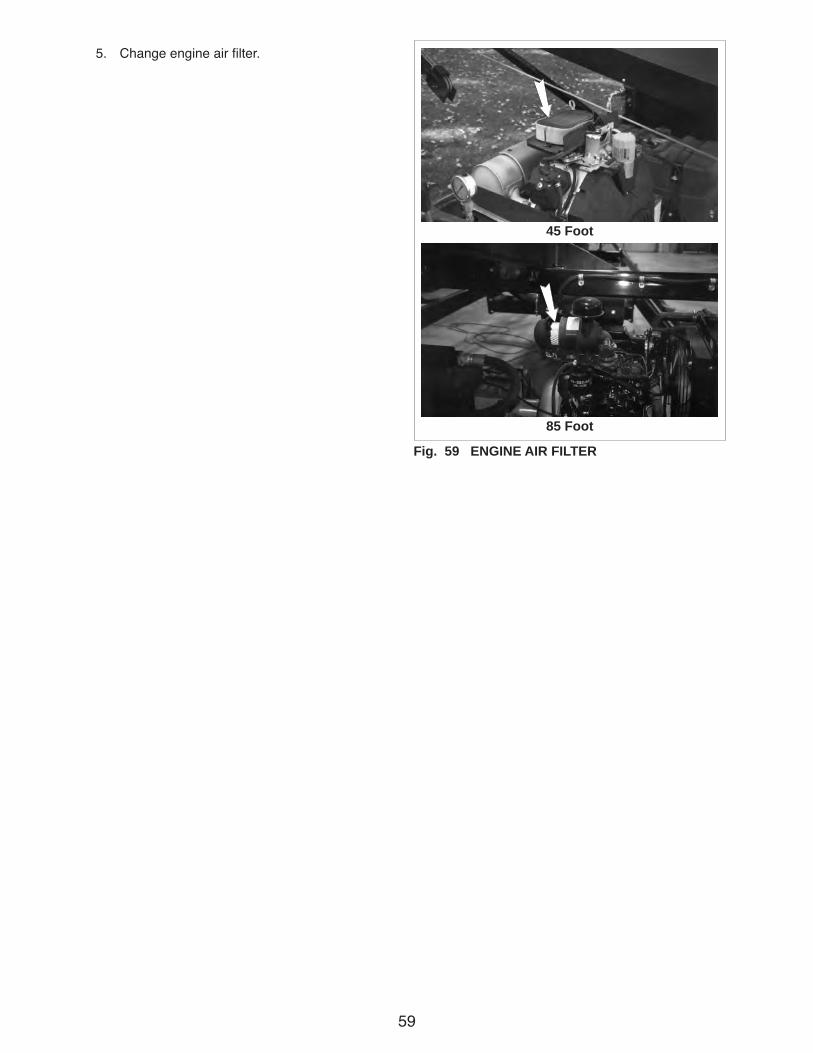
59
5. Change engine air filter.
Fig. 59 ENGINE AIR FILTER
45 Foot
85 Foot
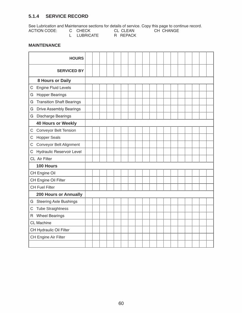
60
5.1.4 SERVICE RECORD
See Lubrication and Maintenance sections for details of service. Copy this page to continue record.ACTION CODE: C CHECK CL CLEAN CH CHANGE L LUBRICATE R REPACK
MAINTENANCE
HOURS
SERVICED BY
8 Hours or DailyC Engine Fluid Levels
G Hopper Bearings
G Transition Shaft Bearings
G Drive Assembly Bearings
G Discharge Bearings
40 Hours or WeeklyC Conveyor Belt Tension
C Hopper Seals
C Conveyor Belt Alignment
C Hydraulic Reservoir Level
CL Air Filter
100 HoursCH Engine Oil
CH Engine Oil Filter
CH Fuel Filter
200 Hours or AnnuallyG Steering Axle Bushings
C Tube Straightness
R Wheel Bearings
CL Machine
CH Hydraulic Oil Filter
CH Engine Air Filter

61
5.2 MAINTENANCE
By following a careful service and maintenance pro-gram for your machine, you will enjoy many years of trouble-free service.
5.2.1 CLEANING AIR CLEANER
1. Review the Operator's manual for the engine.
2. Place all controls in neutral, stop engine and remove ignition key before maintaining.
3. Remove the cover over the air cleaner.
4. Remove the filter from the canister.
5. Use an air hose to blow the dust and debris out of the filter.
6. Install filter.
7. Install and secure the cover.
IMPORTANTDo not allow any dirt or debris to enter intake.
Fig. 60 ENGINE AIR FILTER
45 Foot
85 Foot
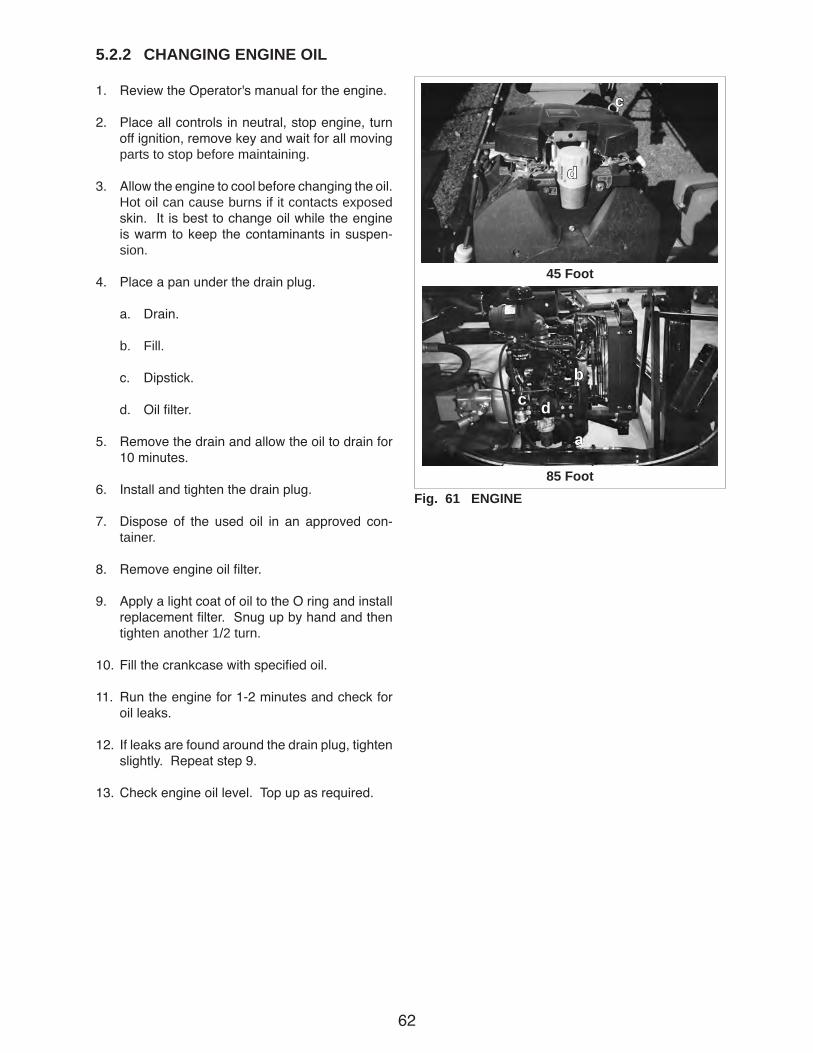
62
5.2.2 CHANGING ENGINE OIL
1. Review the Operator's manual for the engine.
2. Place all controls in neutral, stop engine, turn off ignition, remove key and wait for all moving parts to stop before maintaining.
3. Allow the engine to cool before changing the oil. Hot oil can cause burns if it contacts exposed skin. It is best to change oil while the engine is warm to keep the contaminants in suspen-sion.
4. Place a pan under the drain plug.
a. Drain.
b. Fill.
c. Dipstick.
d. Oil filter.
5. Remove the drain and allow the oil to drain for 10 minutes.
6. Install and tighten the drain plug.
7. Dispose of the used oil in an approved con-tainer.
8. Remove engine oil filter.
9. Apply a light coat of oil to the O ring and install replacement filter. Snug up by hand and then tighten another 1/2 turn.
10. Fill the crankcase with specified oil.
11. Run the engine for 1-2 minutes and check for oil leaks.
12. If leaks are found around the drain plug, tighten slightly. Repeat step 9.
13. Check engine oil level. Top up as required.
Fig. 61 ENGINE
45 Foot
85 Foot
d
a
b
d
c
c

63
5.2.3 CHANGING HYDRAULIC OIL FILTER
1. Review the Operator's manual for the engine.
2. Place all controls in neutral, stop engine, turn off ignition, remove key and wait for all moving parts to stop before maintaining.
3. Allow the engine to cool before changing the filter. Hot oil can cause burns if it contacts ex-posed skin.
4. Place a pan under the filter.
5. Remove the filter and allow any excess oil to drain into the pan.
6. Apply a light coat of oil to the O ring and install replacement filter. Snug up by hand and then tighten another 1/2 turn.
7. Run the engine for 1-2 minutes and check the hydraulic system for oil leaks.
8. If leaks are found around the drain plug, tighten slightly. Repeat step 7.
9. Check oil level in hydraulic reservoir. Top up as required. Fig. 62 HYDRAULIC SYSTEM OIL FILTER
45 Foot
85 Foot

64
5.2.4 CHANGING INLINE FUEL FILTER
1. Review the Operator's manual for the engine.
2. Place all controls in neutral, stop engine, turn off ignition, remove key and wait for all moving parts to stop before maintaining.
3. Allow the engine to cool before changing the inline fuel filter. A hot engine can cause burns if it contacts exposed skin.
4. Place pan under fuel filter to catch any spilled fuel.
5. Clamp the fuel line on both sides of the filter.
6. Loosen fuel filter clamps and remove old filter.
7. Install the replacement filter and reinstall filter clamps.
8. Remove the fuel line clamps.
9. Dispose of any spilled fuel in an approved con-tainer.
10. Run the engine for one to two minutes and check the fuel lines for leaks.
11. If leaks are found at the filter, tighten clamps slightly. Repeat step 10.
Fig. 63 INLINE FUEL FILTER
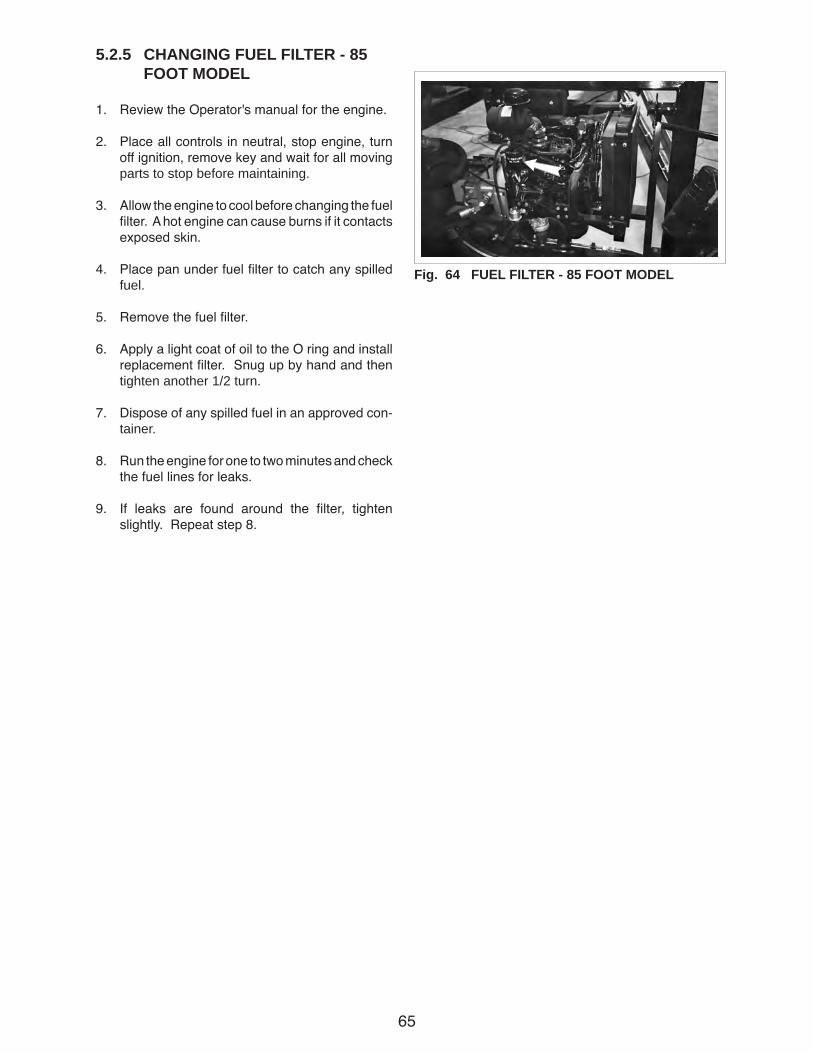
65
5.2.5 CHANGING FUEL FILTER - 85 FOOT MODEL
1. Review the Operator's manual for the engine.
2. Place all controls in neutral, stop engine, turn off ignition, remove key and wait for all moving parts to stop before maintaining.
3. Allow the engine to cool before changing the fuel filter. A hot engine can cause burns if it contacts exposed skin.
4. Place pan under fuel filter to catch any spilled fuel.
5. Remove the fuel filter.
6. Apply a light coat of oil to the O ring and install replacement filter. Snug up by hand and then tighten another 1/2 turn.
7. Dispose of any spilled fuel in an approved con-tainer.
8. Run the engine for one to two minutes and check the fuel lines for leaks.
9. If leaks are found around the filter, tighten slightly. Repeat step 8.
Fig. 64 FUEL FILTER - 85 FOOT MODEL
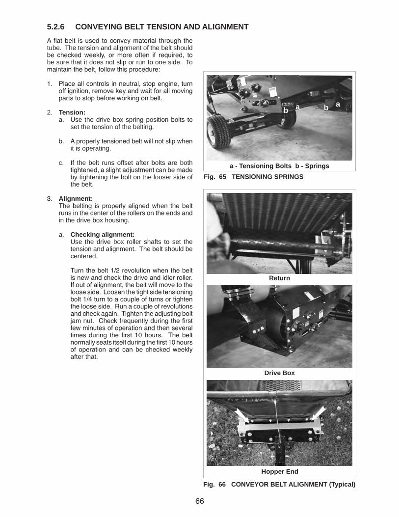
66
5.2.6 CONVEYING BELT TENSION AND ALIGNMENTA flat belt is used to convey material through the tube. The tension and alignment of the belt should be checked weekly, or more often if required, to be sure that it does not slip or run to one side. To maintain the belt, follow this procedure:
1. Place all controls in neutral, stop engine, turn off ignition, remove key and wait for all moving parts to stop before working on belt.
2. Tension: a. Use the drive box spring position bolts to
set the tension of the belting.
b. A properly tensioned belt will not slip when it is operating.
c. If the belt runs offset after bolts are both tightened, a slight adjustment can be made by tightening the bolt on the looser side of the belt.
3. Alignment: The belting is properly aligned when the belt
runs in the center of the rollers on the ends and in the drive box housing.
a. Checking alignment: Use the drive box roller shafts to set the
tension and alignment. The belt should be centered.
Turn the belt 1/2 revolution when the belt is new and check the drive and idler roller. If out of alignment, the belt will move to the loose side. Loosen the tight side tensioning bolt 1/4 turn to a couple of turns or tighten the loose side. Run a couple of revolutions and check again. Tighten the adjusting bolt jam nut. Check frequently during the first few minutes of operation and then several times during the first 10 hours. The belt normally seats itself during the first 10 hours of operation and can be checked weekly after that.
Fig. 66 CONVEYOR BELT ALIGNMENT (Typical)
Fig. 65 TENSIONING SPRINGS
abab
a - Tensioning Bolts b - Springs
Drive Box
Hopper End
Return
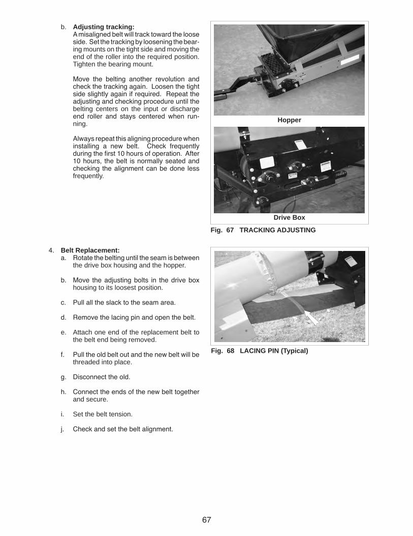
67
b. Adjusting tracking: A misaligned belt will track toward the loose
side. Set the tracking by loosening the bear-ing mounts on the tight side and moving the end of the roller into the required position. Tighten the bearing mount.
Move the belting another revolution and check the tracking again. Loosen the tight side slightly again if required. Repeat the adjusting and checking procedure until the belting centers on the input or discharge end roller and stays centered when run-ning.
Always repeat this aligning procedure when installing a new belt. Check frequently during the first 10 hours of operation. After 10 hours, the belt is normally seated and checking the alignment can be done less frequently.
4. Belt Replacement: a. Rotate the belting until the seam is between
the drive box housing and the hopper.
b. Move the adjusting bolts in the drive box housing to its loosest position.
c. Pull all the slack to the seam area.
d. Remove the lacing pin and open the belt.
e. Attach one end of the replacement belt to the belt end being removed.
f. Pull the old belt out and the new belt will be threaded into place.
g. Disconnect the old.
h. Connect the ends of the new belt together and secure.
i. Set the belt tension.
j. Check and set the belt alignment.
Fig. 67 TRACKING ADJUSTING
Hopper
Drive Box
Fig. 68 LACING PIN (Typical)

68
6 TROUBLE SHOOTINGThe Convey-All Belt Tube Conveyor uses an endless flat belt moving through a tube to convey material from one location to another. It is a simple and reliable system that requires minimal maintenance.
In the following section, we have listed many of the problems, causes and solutions to the problems that you may encounter.
If you encounter a problem that is difficult to solve, even after having read through this trouble shooting section, please call your local Convey-All dealer or distributor. Before you call, please have this Operator's Manual and the serial number from your machine ready.
PROBLEM CAUSE SOLUTION
Engine will not start. Low battery. Recharge or replace.
No fuel. Refuel.
Conveyor will not run. Belting loose. Tighten and align.
Belt frozen to tube from Remove conveyor from area of high operating in high humidity humidity and continue to run empty so conditions in extreme cold. the belt dries prior to stopping and freezing.
Belt edge fraying. Belting not aligned. Align and tension belting.
Low conveying capacity. Conveyor angle exceeds 36°. Reposition with lower tube slope angle.
Incorrect belt speed. Adjust belt speed to correct range (300-350 ft./min.).
Conveyor belt slipping. Tighten and align.
Low volume. Keep hopper full.
Slow belt speed. Increase engine rpm to increase belt speed.

69
PROBLEM CAUSE SOLUTION
Belting won't move. Seized bearing. Check all bearings. Replace any that are rough or seized.
Belting/roller jammed. Check for sticks, stones or other objects jammed in the belt drive area. Remove objects to eliminate jam.
Belting not aligned. Check alignment in the following sequence: 1. Check position of drive box housing fixed shaft. Position at right angles to drive box housing frame. 2. Check and align hopper end roller. 3. Check and align spring tension roller. Set both springs the same. 4. Check for stones or other objects in belt drive areas.
If belt still rides to one side, adjust by loosening the tight side slightly. Run for a short time and check again. Adjust again as required in small steps until the belt is centered.
Belting jammed. Obstruction in belting. Check for obstruction (sticks, stones or other objects) between the tube and belting. Remove the object to allow the belting to move.
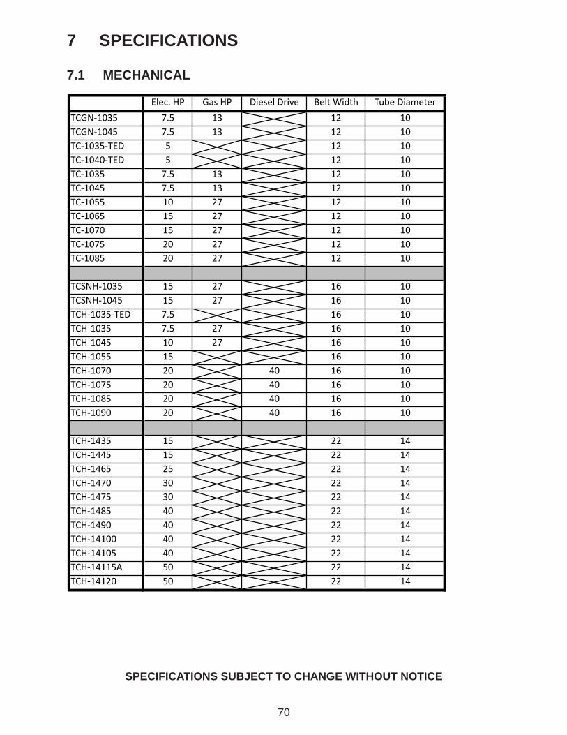
70
7 SPECIFICATIONS
7.1 MECHANICAL
SPECIFICATIONS SUBJECT TO CHANGE WITHOUT NOTICE
Elec.HP GasHP DieselDrive BeltWidth TubeDiameter
TCGN‐1035 7.5 13 12 10
TCGN‐1045 7.5 13 12 10
TC‐1035‐TED 5 12 10
TC‐1040‐TED 5 12 10
TC‐1035 7.5 13 12 10
TC‐1045 7.5 13 12 10
TC‐1055 10 27 12 10
TC‐1065 15 27 12 10
TC‐1070 15 27 12 10
TC‐1075 20 27 12 10
TC‐1085 20 27 12 10
TCSNH‐1035 15 27 16 10
TCSNH‐1045 15 27 16 10
TCH‐1035‐TED 7.5 16 10
TCH‐1035 7.5 27 16 10
TCH‐1045 10 27 16 10
TCH‐1055 15 16 10
TCH‐1070 20 40 16 10
TCH‐1075 20 40 16 10
TCH‐1085 20 40 16 10
TCH‐1090 20 40 16 10
TCH‐1435 15 22 14
TCH‐1445 15 22 14
TCH‐1465 25 22 14
TCH‐1470 30 22 14
TCH‐1475 30 22 14
TCH‐1485 40 22 14
TCH‐1490 40 22 14
TCH‐14100 40 22 14
TCH‐14105 40 22 14
TCH‐14115A 50 22 14
TCH‐14120 50 22 14
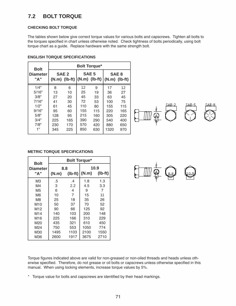
71
7.2 BOLT TORQUE
CHECKING BOLT TORQUE
The tables shown below give correct torque values for various bolts and capscrews. Tighten all bolts to the torques specified in chart unless otherwise noted. Check tightness of bolts periodically, using bolt torque chart as a guide. Replace hardware with the same strength bolt.
ENGLISH TORQUE SPECIFICATIONS
METRIC TORQUE SPECIFICATIONS
SAE 2(N.m) (lb-ft)
Bolt Torque*Bolt
Diameter"A"
SAE 5(N.m) (lb-ft)
SAE 8(N.m) (lb-ft)
1/4"5/16"3/8"7/16"1/2"9/16"5/8"3/4"7/8"1"
81327416195128225230345
6102030456095165170225
12254572110155215390570850
919335380115160290420630
1736631001552203055408801320
12274575115165220400650970
8.8(N.m) (lb-ft)
Bolt Torque*Bolt
Diameter"A"
10.9(N.m) (lb-ft)
M3M4M5M6M8M10M12M14M16M20M24M30M36
.5361025509014022543575014952600
.42.24718376610316632155311031917
1.84.59153570125200310610105021003675
1.33.371126529214822945077415502710
Torque figures indicated above are valid for non-greased or non-oiled threads and heads unless oth-erwise specified. Therefore, do not grease or oil bolts or capscrews unless otherwise specified in this manual. When using locking elements, increase torque values by 5%.
* Torque value for bolts and capscrews are identified by their head markings.
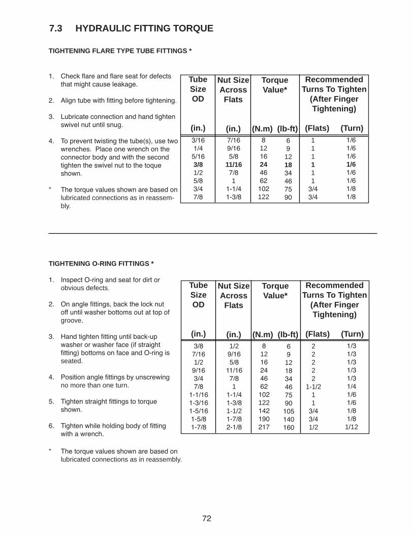
72
TIGHTENING FLARE TYPE TUBE FITTINGS *
7.3 HYDRAULIC FITTING TORQUE
1. Check flare and flare seat for defects that might cause leakage.
2. Align tube with fitting before tightening.
3. Lubricate connection and hand tighten swivel nut until snug.
4. To prevent twisting the tube(s), use two wrenches. Place one wrench on the connector body and with the second tighten the swivel nut to the toque shown.
* The torque values shown are based on lubricated connections as in reassem-bly.
RecommendedTurns To Tighten
(After Finger Tightening)
(Flats) (Turn)
TubeSizeOD
(in.)
Nut SizeAcrossFlats
(in.)
Torque Value*
(N.m) (lb-ft)69121834467590
7/169/165/8
11/167/81
1-1/41-3/8
3/161/45/163/81/25/83/47/8
81216244662102122
111111
3/43/4
1/61/61/61/61/61/61/81/8
TIGHTENING O-RING FITTINGS *
1. Inspect O-ring and seat for dirt or obvious defects.
2. On angle fittings, back the lock nut off until washer bottoms out at top of groove.
3. Hand tighten fitting until back-up washer or washer face (if straight fitting) bottoms on face and O-ring is seated.
4. Position angle fittings by unscrewing no more than one turn.
5. Tighten straight fittings to torque shown.
6. Tighten while holding body of fitting with a wrench.
RecommendedTurns To Tighten
(After Finger Tightening)
(Flats) (Turn)
TubeSizeOD
(in.)
Nut SizeAcrossFlats
(in.)
Torque Value*
(N.m) (lb-ft)69121834467590105140160
1/29/165/8
11/167/81
1-1/41-3/81-1/21-7/82-1/8
3/87/161/29/163/47/8
1-1/161-3/161-5/161-5/81-7/8
81216244662102122142190217
22222
1-1/211
3/43/41/2
1/31/31/31/31/31/41/61/61/81/81/12
* The torque values shown are based on lubricated connections as in reassembly.
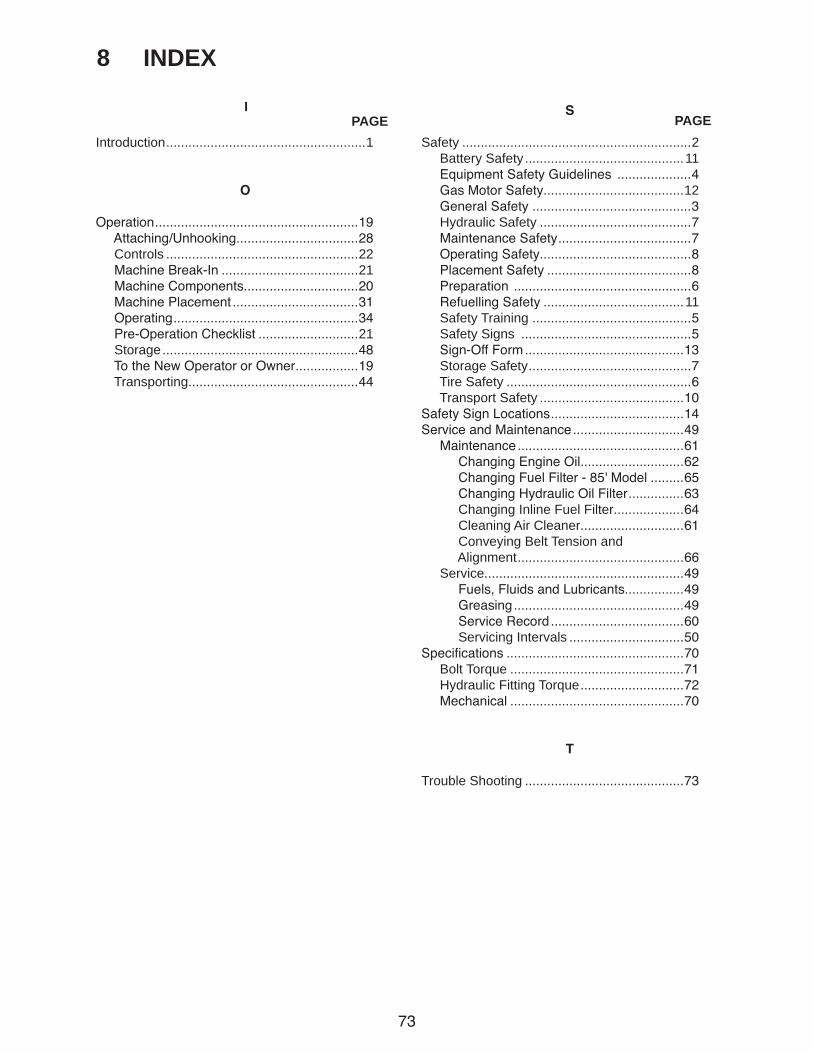
73
8 INDEX
PAGEI
PAGEIntroduction ......................................................1
O
Operation .......................................................19 Attaching/Unhooking.................................28 Controls ....................................................22 Machine Break-In .....................................21 Machine Components...............................20 Machine Placement ..................................31 Operating ..................................................34 Pre-Operation Checklist ...........................21 Storage .....................................................48 To the New Operator or Owner .................19 Transporting..............................................44
S
Safety ..............................................................2 Battery Safety ...........................................11 Equipment Safety Guidelines ....................4 Gas Motor Safety......................................12 General Safety ...........................................3 Hydraulic Safety .........................................7 Maintenance Safety ....................................7 Operating Safety.........................................8 Placement Safety .......................................8 Preparation ................................................6 Refuelling Safety ......................................11 Safety Training ...........................................5 Safety Signs ..............................................5 Sign-Off Form ...........................................13 Storage Safety ............................................7 Tire Safety ..................................................6 Transport Safety .......................................10Safety Sign Locations ....................................14Service and Maintenance ..............................49 Maintenance .............................................61 Changing Engine Oil............................62 Changing Fuel Filter - 85' Model .........65 Changing Hydraulic Oil Filter ...............63 Changing Inline Fuel Filter...................64 Cleaning Air Cleaner............................61 Conveying Belt Tension and Alignment .............................................66 Service......................................................49 Fuels, Fluids and Lubricants................49 Greasing ..............................................49 Service Record ....................................60 Servicing Intervals ...............................50Specifications ................................................70 Bolt Torque ...............................................71 Hydraulic Fitting Torque ............................72 Mechanical ...............................................70
T
Trouble Shooting ...........................................73


CONVEY-ALL INDUSTRIESBOX 2008, 130 CANADA STREET
WINKLER, MANITOBAR6W 4B7
PHONE (204) 325-4195FAX (204) 325-8116
1-800-418-9461
PRINTED IN CANADAISSUE DATE: MAY 2013 PART NUMBER: 26-10MK-0001