Convertible Well Jet Pump Water Systems - Wayne Pumps · PDF file3000-001 316 CWS Series...
32
340009-001 3/16 CWS Series Convertible Well Jet Pump Water Systems OPERATING INSTRUCTIONS & PARTS MANUAL For parts, product & service information visit www.waynepumps.com REMINDER: Keep your dated proof of purchase for warranty purposes! Attach it to this manual or file it for safekeeping. © 2016, WAYNE/Scott Fetzer Company. DESCRIPTION Jet pumps are single stage domestic water pumps designed for pumping potable water in applications where the water is up to 100 feet below pump center line. A pressure switch is a standard feature. A built-in control valve is available on deep well pumps. Deep well pumps can be mounted to either a pre-charged, conventional type, or free standing pressure tank. UNPACKING After unpacking the jet pump, carefully inspect for any damage that may have occurred during transit. Check for loose, missing or damaged parts. SAFETY GUIDELINES To help recognize this information, observe the following signal words/ hazard classifications. Danger indicates an imminently hazardous situation which, if not avoided, WILL result in death or serious injury. Warning indicates a potentially hazardous situation which, if not avoided, COULD result in death or serious injury. Caution indicates a potentially hazardous situation which, if not avoided, MAY result in minor or moderate injury. Notice indicates important information, that if not followed, may cause damage to equipment. This is the safety alert symbol. It is used to alert you to potential bodily injury hazards. Obey all safety messages that follow this symbol to avoid possible harm. NOTE: Information that requires special attention. GENERAL SAFETY INFORMATION CALIFORNIA PROPOSITION 65 This product or its power cord contains chemicals, including lead, known to the State of California to cause cancer and birth defects or other reproductive harm. Wear gloves when handling this product, and wash hands after handling. GENERAL SAFETY 1. Read all manuals included with this product carefully. Be thoroughly familiar with the controls and the proper use of the equipment. 2. Know the pump application, limitations and potential hazards. Always install a pressure relief valve to match the system pressure rating and the maximum flow rate. Do not use to pump flammable or explosive fluids such as gasoline, fuel oil, kerosene, etc. Do not use in explosive atmospheres. Pump should be used to pump ONLY clear water. Failure to follow this warning will result in death or serious injury. Disconnect power and release all pressure from the system before attempting to install, service, relocate or perform any maintenance. Lock the power disconnect in the open (off) position. Tag the power disconnect to prevent unexpected application of power. Install a screen around the inlet pipe to prevent entrapment of swimmers. 3. Drain all water from the system before servicing. 4. Periodically inspect pump and system components. Perform routine maintenance as required (See Maintenance, page 8). 5. Personal Safety: a. Wear safety glasses at all times when working with pumps. b. Keep work area clean, uncluttered and properly lighted replace all unused tools and equipment. c. Keep visitors at a safe distance from work area. d. Make the workshop child proof: use padlocks, master switches and remove starter keys. 6. Do not pump chemicals or corrosive liquids. Pumping these liquids shortens the life of the pumps seals and moving parts and will void the warranty. Pump ONLY clear water. 7. When installing pump, cover the well to prevent foreign matter from falling into well and contaminating the water and damaging internal mechanical pumping components. 8. Always test the water from the well for purity before use. Check with local health department for test procedure. 9. Complete pump and piping system MUST be protected against below freezing temperatures. Freezing temperatures could cause severe damage and void the warranty. 10. Do not run the pump dry or damage will occur and will void warranty. This pump is designed for indoor installation only. Failure to install indoors will significantly increase the risk of injury or death from electrical shock. All wiring should be performed by a licensed or certified electrician. 11. For maximum safety, the unit should be connected to a grounded circuit equipped with a ground fault interrupter device (GFCI). 12. Before installing the pump, have the electrical outlet checked by a licensed or certified electrician to make sure the outlet is properly grounded. Read and save these instructions. This manual contains very important Safety Warnings and Operating Instructions. You will need to refer to it before attempting any installation or maintenance. Always keep this manual with the unit so that it will be easily accessible. Failure to read and follow these warnings and instructions could result in property damage, serious injury or death. Scan QR, or Log on to waynepumps.com and search your model number, to download a multilingual version of this manual Escanee el código QR o visite waynepumps.com y busque su número de modelo para descargar una versión multilingüe de este manual
Transcript of Convertible Well Jet Pump Water Systems - Wayne Pumps · PDF file3000-001 316 CWS Series...

340009-001 3/16
CWS Series
Convertible Well Jet Pump Water Systems OPERATING INSTRUCTIONS & PARTS MANUAL
For parts, product & service information visit www.waynepumps.com
REMINDER: Keep your dated proof of purchase for warranty purposes! Attach it to this manual or file it for safekeeping.
© 2016, WAYNE/Scott Fetzer Company.
DESCRIPTIONJet pumps are single stage domestic water pumps designed for pumping potable water in applications where the water is up to 100 feet below pump center line. A pressure switch is a standard feature. A built-in control valve is available on deep well pumps. Deep well pumps can be mounted to either a pre-charged, conventional type, or free standing pressure tank.
UNPACKINGAfter unpacking the jet pump, carefully inspect for any damage that may have occurred during transit. Check for loose, missing or damaged parts.
SAFETY GUIDELINESTo help recognize this information, observe the following signal words/hazard classifications.
Danger indicates an imminently hazardous situation which, if not avoided, WILL result in
death or serious injury.
Warning indicates a potentially hazardous situation which, if not avoided, COULD result in
death or serious injury.
Caution indicates a potentially hazardous situation which, if not avoided, MAY result in
minor or moderate injury.
Notice indicates important information, that if not followed, may cause damage to equipment.
This is the safety alert symbol. It is used to alert you to potential bodily injury hazards. Obey all safety messages that follow this symbol to avoid possible harm.
NOTE: Information that requires special attention.
GENERAL SAFETY INFORMATION
CALIFORNIA PROPOSITION 65
This product or its power cord contains chemicals, including lead, known to the State of
California to cause cancer and birth defects or other reproductive harm. Wear gloves when handling this product, and wash hands after handling.
GENERAL SAFETY
1. Read all manuals included with this product carefully. Be thoroughly familiar with the controls and the proper use of the equipment.
2. Know the pump application, limitations and potential hazards.
Always install a pressure relief valve to match the system pressure rating and the
maximum flow rate.
Do not use to pump flammable or explosive fluids such as gasoline,
fuel oil, kerosene, etc. Do not use in explosive atmospheres. Pump should be used to pump ONLY clear water. Failure to follow this warning will result in death or serious injury.
Disconnect power and release all pressure from the system before attempting to install, service,
relocate or perform any maintenance. Lock the power disconnect in the open (off) position. Tag the power disconnect to prevent unexpected application of power.
Install a screen around the inlet pipe to prevent entrapment of swimmers.
3. Drain all water from the system before servicing.
4. Periodically inspect pump and system components. Perform routine maintenance as required (See Maintenance, page 8).
5. Personal Safety:
a. Wear safety glasses at all times when working with pumps.
b. Keep work area clean, uncluttered and properly lighted replace all unused tools and equipment.
c. Keep visitors at a safe distance from work area.
d. Make the workshop child proof: use padlocks, master switches and remove starter keys.
6. Do not pump chemicals or corrosive liquids. Pumping these liquids shortens the life of the pumps seals and moving parts and will void the warranty. Pump ONLY clear water.
7. When installing pump, cover the well to prevent foreign matter from falling into well and contaminating the water and damaging internal mechanical pumping components.
8. Always test the water from the well for purity before use. Check with local health department for test procedure.
9. Complete pump and piping system MUST be protected against below freezing temperatures. Freezing temperatures could cause severe damage and void the warranty.
10. Do not run the pump dry or damage will occur and will void warranty.
This pump is designed for indoor installation only. Failure to install
indoors will significantly increase the risk of injury or death from electrical shock.
All wiring should be performed by a licensed or certified electrician.
11. For maximum safety, the unit should be connected to a grounded circuit equipped with a ground fault interrupter device (GFCI).
12. Before installing the pump, have the electrical outlet checked by a licensed or certified electrician to make sure the outlet is properly grounded.
Read and save these instructions. This manual contains very important Safety Warnings and Operating Instructions. You will need to refer to it before attempting any installation or maintenance. Always keep this manual with the unit so that it will be easily accessible. Failure to read and follow these warnings and instructions could result in property damage, serious injury or death.
Scan QR, or Log on to waynepumps.com and search your model number, to download a multilingual version of this manualEscanee el código QR o visite waynepumps.com y busque su número de modelo para descargar una versión multilingüe de este manual
2
www.waynepumps.com
Operating Instructions and Parts Manual
GENERAL SAFETY INFORMATION (CONTINUED)13. Make sure the line voltage and frequency of electrical current supply
agrees with the motor wiring.
14. Do not attempt repairs to the electric motor. All repairs to the motor must be completed at a licensed or certified electrical motor repair shop.
Do not touch an operating motor. Modern motors are designed to operate at high
temperatures.
15. Avoid kinking electrical cord and protect electrical cord from sharp objects, hot surfaces, oil and chemicals. Replace damaged or worn cords immediately.
16. Keep fingers and foreign objects away from ventilation and other openings. Do not insert any objects into the motor.
Risk of electric shock! Never connect the green (or green and yellow wire) to a live terminal!
17. Use wire of adequate size to minimize voltage drop at the motor.
Do not handle pump or pump motor with wet hands, when standing on a wet or damp surface
or when standing in water. Fatal electrical shock will occur.
Pump motor is equipped with an automatic resetting thermal protector and may restart
unexpectedly. Protector tripping is an indication of motor overheating because of operating pump at low heads (low discharge restriction), excessively high or low voltage, inadequate wiring, incorrect motor connections,excessive surrounding air temperature, inadequate ventilation, and/or defective motor or pump.
PRE-INSTALLATION
WATER SUPPLIES
The water supplies illustrated in Figure 16 (on page 10) are possible sources for water. These water supplies can be divided into two categories:
SURFACE WATER
Water from a lake, stream, pond and cistern. This water is usually not fit for human consumption, but may be suitable for washing, irrigation or other household uses.
GROUND WATER
Water found in the water bearing stratum at various levels beneath the earth. Of all the fresh water found on earth only 3 percent is found on the surface and 97 percent is underground.
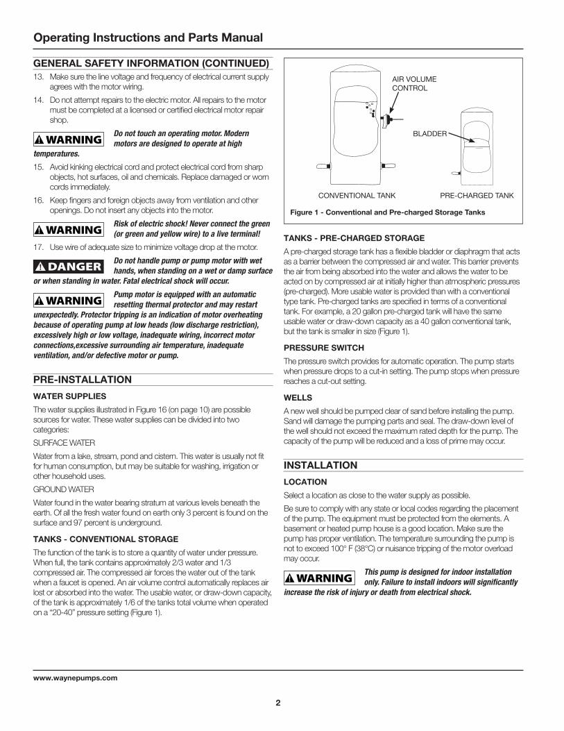
TANKS - CONVENTIONAL STORAGE
The function of the tank is to store a quantity of water under pressure. When full, the tank contains approximately 2/3 water and 1/3 compressed air. The compressed air forces the water out of the tank when a faucet is opened. An air volume control automatically replaces air lost or absorbed into the water. The usable water, or draw-down capacity, of the tank is approximately 1/6 of the tanks total volume when operated on a “20-40” pressure setting (Figure 1).
TANKS - PRE-CHARGED STORAGE
A pre-charged storage tank has a flexible bladder or diaphragm that acts as a barrier between the compressed air and water. This barrier prevents the air from being absorbed into the water and allows the water to be acted on by compressed air at initially higher than atmospheric pressures (pre-charged). More usable water is provided than with a conventional type tank. Pre-charged tanks are specified in terms of a conventional tank. For example, a 20 gallon pre-charged tank will have the same usable water or draw-down capacity as a 40 gallon conventional tank, but the tank is smaller in size (Figure 1).
PRESSURE SWITCH
The pressure switch provides for automatic operation. The pump starts when pressure drops to a cut-in setting. The pump stops when pressure reaches a cut-out setting.
WELLS
A new well should be pumped clear of sand before installing the pump. Sand will damage the pumping parts and seal. The draw-down level of the well should not exceed the maximum rated depth for the pump. The capacity of the pump will be reduced and a loss of prime may occur.
INSTALLATION
LOCATION
Select a location as close to the water supply as possible.
Be sure to comply with any state or local codes regarding the placement of the pump. The equipment must be protected from the elements. A basement or heated pump house is a good location. Make sure the pump has proper ventilation. The temperature surrounding the pump is not to exceed 100° F (38°C) or nuisance tripping of the motor overload may occur.
This pump is designed for indoor installation only. Failure to install indoors will significantly
increase the risk of injury or death from electrical shock.
Figure 1 - Conventional and Pre-charged Storage Tanks
AIR VOLUME CONTROL
CONVENTIONAL TANK PRE-CHARGED TANK
BLADDER

3
www.waynepumps.com
CWS Series
PIPING
Piping may be copper, steel, rigid PVC plastic or flexible polyethylene plastic.
Flexible pipe is not recommended on suction pipe (inlet pipe).
The pipe must be clean and free of rust or scale. Use a pipe joint compound on the male threads of the metal pipe. Plumber’s seal tape should be used with plastic threads. All connections must be air tight to insure normal operation.
Slope all inlet piping upwards towards the pump to prevent trapping air. Unions or hose couplings can be installed near pump to facilitate removal for servicing or storage. A rubber hose installed between the water system and the house piping will reduce the noise transmitted to the house.
Plastic pipe can be used on all installations except 2 in. deep well jet. The 2 in. deep well jet requires 1-1/4 in. galvanized steel pipe and special machined couplings (1-13/16 in. O. D.).
The galvanized steel pipe and the couplings restrict the flow of return water back to the jet unless the couplings are machined.
PIPE SIZES
Long horizontal pipe runs and an abundance of fittings and couplers decrease water pressure due to friction loss. See Chart 1, on page 5, to determine the proper pipe size.
SHALLOW WELL INSTALLATION
A shallow well jet assembly can be used with the deep well pump when the pump is located 25 feet vertically of the water level (See converting to shallow well pump on page 6). Shallow well installations have only one pipe between the pump and water supply (Figure 2).
DRILLED WELL (FIGURE 16)
1. Install a foot valve on the first section of pipe (Figure 2, Illustration A).
2. Lower the pipe into the well.
3. Add pipe until the foot valve is 5 feet below the lowest anticipated water level.
The foot valve should be at least 18 in. from the bottom of the well or sand or sediment could be
drawn into the system.
4. After proper depth is reached, install a well seal or pitless adapter to support pipe and prevent surface. water and other contaminants from entering well.
5. Slope the horizontal pipe upward toward the pump to eliminate trapping air. Sloping the pipe will also aid in priming the pump.
DRIVEN WELL
• Drive the point several feet below the water table.
NOTE: A packer type foot valve can be installed in the well (Figure 2, Illustration B). This type of foot valve allows the piping to be filled with water when priming and makes the inlet pipe much easier to test for leaks. Follow the manufacturer’s instructions when installing the packer type foot valve.
As an alternative, an in-line check valve can be used with a driven well (Figure 2, Illustration C). The pipe between the check valve and the water level will always be under a vacuum.
TO PUMP
WELL SEAL
FOOT VALVE
WELL CASING
TO PUMP
INLINE CHECK VALVE
PACKER TYPE FOOT VALVE
ILLUSTRATION A
ILLUSTRATION C
ILLUSTRATION B
Figure 2
TO PUMP
DRIVE POINT
DRIVE POINT

4
www.waynepumps.com
Operating Instructions and Parts Manual
INSTALLATION (CONTINUED)Leaking joints or couplings will allow air to leak into the pipe and cause abnormal pump operation. Make sure to use pipe joint compound on all male pipe threads.
DUG WELL, CISTERN, LAKE AND SPRING INSTALLATION (FIGURE 16, ON PAGE 10)
• Install a foot valve on inlet pipe and lower into water.
The foot valve should be at least 18 in. from the bottom of the well or sand or sediment could be
drawn into the system.
NOTE: When a lake is used as a water supply, make sure the inlet pipe is deep enough to be submerged at all times.
Slope the horizontal piping upward toward the pump to prevent trapping air. The pipe must be removed during winter months or protected against freezing.
Protect the pipe from damage from swimmers and boats.
Install a screen around the inlet pipe to prevent the entrapment of swimmers.
DEEP WELL INSTALLATION
DRILLED WELL (4 IN. OR LARGER) WITH TWO PIPE JET (FIGURES 16, ON PAGE 10 AND 3, ON PAGE 4)
1. Assemble a 1-1/4 in. foot valve (not included) to the jet body. A 1-1/4 in. coupling is required to connect the larger pipe to the jet assembly.
2. Connect the 1 in. pipe threads into the smaller opening in the jet body.
3. Lower the jet into the well. Add pipe as needed. Be sure to use pipe joint compound, or plumber’s seal tape on all male threads.
4. Position the jet 10 - 20 feet below the lowest anticipated water level, but never closer than 5 feet from the bottom of the well, if possible.
5. Install a well seal to support the pipe and prevent surface water and other contaminants from entering the well.
6. Install the horizontal pipe from the well to the pump. Piping from the vertical well pipe to the pump should never be smaller than the well pipes.
7. Slope both pipes upward toward the pump to prevent trapping air. If the horizontal distance exceeds 25 feet, see Chart 1 for the recommended pipe sizes.
DUG WELL, CISTERN, LAKE AND SPRING WITH TWO PIPE JET (FIGURE 16, ON PAGE 10)
1. Install a 1-1/4 in. foot valve (not included) to the jet body. A 1-1/4 in. coupling is required to connect the larger pipe to the jet assembly.
2. Connect the 1 in. pipe threads into the smaller opening in the jet body.
3. Lower the jet into the water below the lowest anticipated water level, but never closer than 18 in. from the bottom. Sand or debris may be drawn into the system if the jet is too close to the bottom.
4. Provide protection for the jet and pipes against damage from boats or swimmers if a lake is used for the water supply.
Install a screen around the inlet pipe to prevent the entrapment of swimmers.
5. Slope the horizontal pipes upward toward the pump to prevent trapping air. If horizontal distance exceeds 25 feet, see Chart 1 for recommended pipe sizes.
DRILLED WELL (2 IN.) WITH SINGLE PIPE PACKER (FIGURES 16 AND 4)
NOTE: Single pipe packer jets rely on the space between single pipe and inside of well casing for return water to operate jet. Two inch installations must use 1-1/4 in. galvanized steel pipe with special turned couplings (1-13/16 in. O.D.) to avoid restricting flow of return water back to jet.
1. Assemble the foot valve and packer to the jet body.
2. Lubricate the rubber cups with petroleum jelly.
3. Attach the first section of pipe and lower jet into well.
4. Add pipe until the jet is positioned 5 - 15 feet below the lowest anticipated water level. The jet should never be closer than 5 feet from the bottom of the well or sand and sediment may be drawn into the system.
5. With the jet in position, fill the pipes with water to make sure the rubber cups are sealed against inside of the well casing. It may be necessary to move the jet up and down to seat the cups.
6. Install the casing adapter and the horizontal pipes.
7. Slope both pipes upward toward the pump to eliminate trapping air. If the horizontal distance exceeds 25 feet, see Chart 1 for the recommended pipe sizes.
Figure 3 - Two Pipe Jet
JET BODY
FOOT VALVE
1-1/4 IN. PIPE
1 IN. PIPE
1-1/4 IN. PIPE
Figure 4 - Single Pipe Jet
PACKERFOOT VALVE
CUPS

5
www.waynepumps.com
CWS Series
CHART 1 - PIPE SIZING
Pump ModelPump
Opening
Horizontal Distance (Feet)
0-25 26-100
Deep Well Inlet: Suction 1-1/4 in. 1-1/2 in.
Inlet: Drive 1 in. 1-1/4 in.
Outlet 3/4 in. 1 in.
DEEP WELL PUMP WITH HORIZONTAL AND VERTICAL STORAGE TANK (FIGURES 5 AND 6)
1. Install the air volume control on the tank as shown.
2. Connect the copper tube from the air volume control to the 1/8 in. NPT opening directly above the 1-1/4 in. opening on the front of the pump.
3. Install a valve and isolating hose between the system and the house plumbing to aid in pump removal for servicing and for reducing noise transmitted through the house piping.
4. Provide a hose bib (faucet) at the lowest point in the system to drain for service or storage.
DEEP WELL PUMP WITH PRE-CHARGED STORAGE TANK (FIGURE 7)
1. Check tank pre-charge using a tire pressure gauge. Set air pressure in tank to 28 psi which is 2 psi below pressure switch cut-in level. An air valve is located on the side and will accept a standard fitting from a bicycle pump or air line.
2. Check the pressure with the power off, faucets open and no water flowing (zero water pressure).
3. Install a valve and isolator hose between the system and the house plumbing to aid in pump removal for servicing and for reducing noise transmitted to the house through the piping.
4. Provide a hose bib (faucet) at the lowest point in the system to drain for service or storage.
Figure 6 - Vertical Tank
OUTLET
AIR VOLUME CONTROL
TUBING
PRIMING PLUG
SUCTION
AIR VOLUME CONTROL
DRIVE
Figure 5 - Horizontal Tank
AIR VOLUME CONTROL TUBING
OUTLET
AIR VOLUME
CONTROL
PRESSURE SWITCH
PRIME PLUG TO JET
Figure 7 - Pre-charged Storage Tank
OUTLET PRIME PLUG
TO JET
PRESSURE SWITCH

6
www.waynepumps.com
Operating Instructions and Parts Manual
INSTALLATION (CONTINUED)CONVERTING THE DEEP WELL PUMP TO SHALLOW WELL OPERATION (FIGURE 8)
For shallow wells (25 feet or less), a bolt-on shallow well jet is available as an accessory for deep well pumps. The jet attaches to the front of the pump with the two bolts provided and converts the deep well pump into a shallow well pump. The shallow well jet has a 1 in. NPT inlet and a 1/8 in. NPT opening for an air volume control. For optimum performance, an inline check valve on the inlet side of the shallow well jet is recommended.
ELECTRICAL
Risk of electrical shock. This pump is designed for indoor installation only.
Select the proper size wire and fuse (Chart 2). Time delay fuses are recommended over standard fuses for motor circuit protection. All pump motors have built-in automatic overload protection that will prevent damage to the motor due to overheating.
Do not connect to electric power supply until unit is permanently grounded. Connect ground
wire to approved ground then connect terminal provided.
A metal underground water pipe or well casing at least 10 feet long makes the best ground electrode. If plastic pipe or insulated fittings are used, run a wire directly to the metal well casing or use a ground electrode furnished by the power company.
There is only one proper ground terminal on the unit. The terminal is located under the pressure switch cover, is painted green and is identified as GRD. The ground connection must be made at this terminal (Figure 9).
The ground conductor must not be smaller than the circuit conductors supplying the motor.
The voltage of power supply must match the voltage of the pump. The unit has dual voltage motors preset at the factory to 115 volts. The motors can be converted to 230 volts by turning the voltage selector to the desired voltage (see Figure 10, on page 6). Disconnect power, use needle nose pliers to pull the selector out approximately 1/4 in., rotate, and then reinsert in correct position.
Disconnect power and release all pressure from the system before attempting to install, service,
relocate or perform any maintenance.
CHART 2 - RECOMMENDED FUSE AND WIRING DATA - 60 HZ MOTORS
HP Volt
Dual Element
Fuse 250V
Distance in Feet From Meter to Motor
0 51 101to to to50 100 200
Wire Size
1/2115 20 14 12 10
230 10 14 14 14
3/4115 20 14 12 8
230 10 14 14 14
1115 20 14 12 8
230 10 14 14 14
Figure 10 - Voltage Selector
230 V 115 V
L2 3
L1 1
Figure 9 - Electrical Connections
MOTOR
LINEGROUND SCREW
Figure 8 - Shallow Well Jet
TO AIR VOLUME CONTROL
JET ASSEMBLY

7
www.waynepumps.com
CWS Series
OPERATION
PRIMING THE SHALLOW WELL PUMP
To prevent damage to the pump, do not start motor until pump has been filled with water.
NOTE: When the deep well pump is used with the bolt-on shallow well jet, be sure the control valve slot (Figure 11) is in the vertical (open) position at all times.
1. Remove prime plug.
2. Fill pump and piping completely full of water.
3. Replace the prime plug.
4. Open a faucet to vent the system.
5. Start the motor. Water will pump in a few minutes. If pump fails to prime in 5 minutes, stop motor and refill pump with water. Priming time is proportional to the amount of air in inlet pipe. Do not allow pump to get hot.
6. Let the system operate for several minutes to flush all pipes.
7. Close faucet and allow pump to build pressure in tank. When the pressure reaches the cut-out setting, the motor will stop.
The system is now in operation and will automatically cycle on demand.
PRIMING THE DEEP WELL PUMP
To prevent damage to the pump, do not start motor until pump has been filled with water.
1. Remove prime plug.
2. Fill pump and piping completely full of water.
3. Replace the prime plug.
4. Close the control valve (Figure 11) and open a nearby faucet.
5. Start the motor. The pressure inside the pump body will build almost immediately as the pump, jet and piping become completely filled with water.
6. Slowly open the control valve. Water will begin to flow. Continue to open the control valve until maximum flow is achieved. Opening the valve too far will cause the water to stop flowing.
7. Adjust the valve until there is a steady flow of water. The valve should be opened as much as possible without losing pressure.
8. Let the system operate for several minutes to flush all piping.
9. Close the faucets and allow the pump to build pressure in the tank. When the pressure reaches the cut-out setting, the motor will stop.
Figure 11 - Control Valve
OPEN
1/4 IN. TURN
CLOSED
The system is now in operation and will automatically cycle upon demand.
MAINTENANCE Disconnect power and release all pressure from
the system before attempting to install, service, relocate or perform any maintenance. Lock the power disconnect in the open (off) position. Tag the power disconnect to prevent unexpected application of power.
Protect the pump from freezing during winter conditions.
DRAINING THE PUMP
Drain openings are provided on all models. To drain the pump:
1. Remove drain plug and prime plug to vent the system.
2. Drain all piping to a point below the freeze line.
DRAINING THE TANK
Conventional tanks can be drained by opening an outlet at the lowest point in the system. Remove plug or the air volume control to vent the tank.
Pre-charged tanks force virtually all the water from the tank when system pressure is released. No draining is necessary.
RESTARTING PUMP
If the pump has been serviced, drained or has not been used for some time, be sure there is water in the pump housing (volute) and the piping to the well. There must be water in the pump housing (volute) at all times when the pump is running to avoid internal damage of seal members (See Priming the Shallow Well or Priming the Deep Well Sections).
WATERLOGGED TANKS: CONVENTIONAL
When a tank system has an inadequate ratio of air and water, the pump will start and stop often and erratically.
1. Disconnect the power to the pump.
2. Open the lowest faucet in the system to release all pressurized water in the system.
3. Prime the pump (See Priming the Shallow Well or Priming the Deep Well Sections).
4. Reconnect the power to the pump.
NOTE: As the pump refills the tank with water, the air volume control supplies the tank with the correct air to water ratio for the system to operate. If the air volume control is good, the pump will shut off at the desired cut-off and will be adjusted correctly.
WATERLOGGED TANKS: PRE-CHARGED
If a pre-charged tank becomes waterlogged, the bladder is normally leaking or broken.
1. Test the tank by depressing the air valve. The air valve will expel water if the bladder is broken.
2. Replace the tank.
NOTE: Once a bladder is leaking or broken, the bladder cannot be repaired. The tank must be replaced.

8
www.waynepumps.com
Operating Instructions and Parts Manual
MAINTENANCE (CONTINUED)
PRE-CHARGED TANK
Some air is lost through the bladder in any tank. To prevent tank failure, check the tank pre-charge on a yearly basis.
1. Disconnect power to the pump
2. Open a faucet nearest the tank and allow all water to drain from the tank.
3. Measure the tank pre-charge at the valve stem using a tire gauge.
4. If necessary, adjust the pre-charge with an air pump 28 - 30 psi on 1/2, 3/4 and 1 HP pumps.
LUBRICATION
The bearing used in the pumps are lifetime lubricated at the factory and require no additional lubrication.
CWS REPAIR KIT
1. Disconnect power from the pump.
2. Open faucet nearest the tank and allow all of the water to drain from the tank and pump.
3. Remove 4 cap screws holding pump housing, do not disconnect pressure switch. (Figure 12)
4. Remove pump housing from pump assembly, move it out of the way.
5. Using a 5/16” socket or flat blade screw drive remove the 2 screws from the diffuser on the pump assembly.
6. Remove the diffuser.
7. Remove the black plastic cap from the back of the motor, exposing the motor shaft end.
8. Using a large flat bladed screw driver hold the motor shaft while unscrewing the impeller.
9. Remove the seal plate. Pay attention to how the original shaft seal is installed before disassembly.
10. Remove the shaft seal from the impeller, make sure the stainless steel sleeve comes off the impeller, all you should see on the back of the impeller is the brass colored threaded insert. (Figure 13)
11. Remove the ceramic seat and rubber boot part of the seal from the cast iron seal plate. (Figure 13)
12. Remove the square cut gasket from the seal plate.
13. Reassemble the pump with new parts in reverse order.
14. Wipe down the seal plate to remove any debris or loose rust.
15. Push the ceramic seat of the shaft seal into the seal plate using the cardboard ring provided to keep the ceramic face clean. You can use a little water or dish soap to lubricate the seal pocket to make assembly easier.
16. Slide the square cut gasket over the flange on the seal plate, make sure not to let the gasket twist.
17. Carefully slip the seal plate over the shaft so as not to disturb seal position in the seal plate. The seal plate must be orientated during assembly so the two holes are on a horizontal line across the motor shaft. (Figure 14)
Figure 13 - Removing Shaft Seal and Ceramic Seat
ROTATING SHAFT SEAL MEMBER
RUBBER SEAT RING
IMPELLERSEAL PLATE
CERAMIC SEAT
Figure 12 - Convertible Well Pump
CAP SCREWS
MOTOR
SEAL PLATE
IMPELLER
DIFFUSER
PUMP HOUSING (VOLUTE)
DRAIN PLUG
Figure 14 - Seal Plate Replacement
SCREW HOLES
MOTOR SHAFT
SQUARE CUT RING
SEAL

9
www.waynepumps.com
CWS Series
18. Push the bellows side of the shaft seal over the impeller hub, you can use a little water or dish soap to lubricate the impeller hub to make assembly easier. (Figure 15) Make sure after assembly the back carbon and white ceramic surfaces are in contact.
19. Holding the motor shaft with a flat blade screw driver thread the impeller onto the motor shaft, hand tighten. Lubricate the nose of the impeller with potable water safe lubricant.
20. Replace the plastic cap over the motor shaft end.
21. Reassemble the diffuser, make sure the arrow indicating the top is pointed toward the top of the pump, torque the two screws to 30 ±10 inch pounds.
22. Using the (4) cap screws reattach the pump housing and base to the pump body. Torque the screws to 140 ±40 inch pounds.
23. Reattach the plumbing connections, reconnect the power and prime the pump (See section on priming the pump). After reassembling the pump check for leaks. If a leak is detected, repair before using the pump.
SEAL PLATE
Figure 15 - Motor Shaft
MOTOR
IMPELLER
SEAL SEAT
SEAL PLATE
SEAL FACING MUST
BE CLEAN FOR PROPER SEAL

10
www.waynepumps.com
Operating Instructions and Parts Manual
(A) SPRING:�
A spring that emerges �
from the ground. �
Occurs when water in �
permeable materials is �
trapped between �
impermeable�
material as rock or clay.
(B) LAKE, STREAM or POND:�
Surface water, unless treated,�
is usually not safe for human�
consumption. It may be used�
for purposes such as washing�
or irrigation.
(C) DUG WELL:�
A hole is excavated�
several feet in diameter�
to a fairly shallow �
depth. It is then lined�
with brick, stone or�
concrete to prevent�
cave-in.
(D) DRIVEN WELL:�
Pipe with a pointed�
screen is driven into�
the ground below �
the water table. �
The depth is usually�
less than 50 feet. �
Available �
diameters are �
1" through 2".
(E) DRILLED WELL:�
A hole bored into the �
earth with machinery and�
lined with pipe. Depths �
range from a few feet �
to over 1000 feet.�
Common well diameters �
are 2", 3", 4" and 6" for�
domestic water wells.
(F) CISTERN:�
An underground tank �
built to collect rain
water from rooftops.�
The water is not fit�
for human consumption
�
�
(A) SPRING
(B) LAKE, �
STREAM, POND�
�
(C) DUG WELL
(D) DRIVEN WELL(E) DRILLED WELL(F) CISTERN
SHALE
TOP SOIL
CLAY
PERMEABLE�
MATERIAL
WATER�
BEARING�
SAND
WATER TABLE
�
WA
TE
R S
UP
PLIE
S
Figure 16 - W
ater Sup
plies

11
www.waynepumps.com
CWS Series
TROUBLESHOOTING CHART
Symptom Possible Cause(s) Corrective ActionPump will not run 1. Power off 1. Turn power on or call power com pa ny
2. Blown fuse or tripped breaker 2. Replace fuse or reset circuit break er
3. Faulty pressure switch 3. Replace switch
4. Motor overload tripped 4. Let cool. Overload will au to mat i cal ly re set
5. Low line voltage 5. Contact an electrician
Motor hums but will not run 1. Line voltage does not match selector switch 1. Check voltage
2. Wiring too small 2. Rewire
3. Damage or misalignment causing rotating parts to bind
3. Replace or take to service shop for re pair
4. Low line voltage 4. Contact an electrician
Overload trips 1. Low line voltage 1. Contact an electrician
2. Damage or misalignment causing rotating parts to bind
2. Take to motor repair shop or locate and repair mechanical binding
3. High surrounding temperature 3. Provide a shaded, well-ventilated area for pump
4. Rapid cycling 4. See “Pump starts and stops too often” sec tion
5. Inadequate wiring 5. Rewire
Pump runs but delivers little or no water
Note: Check prime before looking for other causes. Unscrew priming plug and see if water is in priming hole.
1. Water level below pump intake 1. Lower suction pipe further into well
2. Control valve open too far (deep well) 2. Adjust control valve or repeat priming procedure.
3. Discharge not vented while priming 3. Open faucet, repeat priming pro ce dure
4. Leaking in piping on well side of pump 4. Repair piping as needed
5. Well screen or inlet strainer clogged 5. Clean or replace as necessary
6. Clogged nozzle (deep well) 6. Pull jet and clear obstruction
7. Air volume control diaphragm ruptured 7. Replace air volume control (See Page 6)
8. Foot valve may be clogged or stuck closed 8. Clean or replace as needed
9. Pump not fully primed 9. Continue priming, paus ing ev ery 5 min utes to cool pump body. Refill pump as need ed
10. Control valve completely closed (deep well) 10. Adjust control valve per deep well prim ing procedure (see page 7)
11. Water level below maximum lift spec i fi cation
11. Select applicable pump and/or jet as sem bly
12. Undersized piping 12. Replace as needed
13. Gaseous well 13. Install baffle on pump intake to pre vent gas from entering system
14. Distorted venturi 14. Inspect and replace
15. Incorrect jet for application 15. Purchase a jet matched to your sys tem when replacing another brand pump
16. Undersized pump 16. Increase horsepower of pump
17. Pump cavitates, (sounds like pumping gravel)
17. Increase suction plumbing diameter or decrease pipe friction
18. Low line voltage 18. Contact an electrician
Pump starts and stops too of ten 1. Water logged tank (conventional tank) 1. See waterlogged conventional tank on page 7
2. Air volume control tubing kinked or clogged 2. Clean or replace as needed
3. Air volume control tubing connected to wrong opening on pump
3. Move to correct pump opening
4. Incorrect tank pre-charge (pre-charged tank)
4. Add or release air as needed
5. Ruptured diaphragm/bladder (pre-charged tank)
5. Replace tank
6. Leak in house piping 6. Locate and repair leak
7. Foot valve or check valve stuck open 7. Remove and replace
8. Motor overload tripping 8. See overload trips section
9. Faulty pressure switch 9. Replace switch
12
www.waynepumps.com
Operating Instructions and Parts Manual
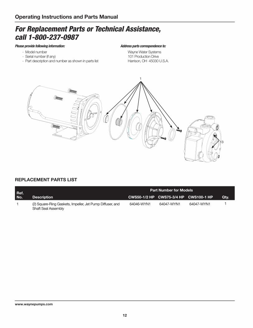
For Replacement Parts or Technical Assistance, call 1-800-237-0987Please provide following information:
- Model number- Serial number (if any)- Part description and number as shown in parts list
Address parts correspondence to:
Wayne Water Systems101 Production DriveHarrison, OH 45030 U.S.A.
13
REPLACEMENT PARTS LIST
Ref. No.
Part Number for Models
Description CWS50-1/2 HP CWS75-3/4 HP CWS100-1 HP Qty.
1 (2) Square-Ring Gaskets, Impeller, Jet Pump Diffuser, and Shaft Seal Assembly
64046-WYN1 64047-WYN1 64047-WYN1 1
1

13
www.waynepumps.com
CWS Series
PERFORMANCE
Model No. Motor HPSuction Lift (Feet)
Discharge Pressure PSI
30 40 50
Output in Gallons Per Hour (GPH)
CWS50 1/2
0 10 20 30 40
900
780
690
570
456
660
570
450
348
270
408
300
210
150
60
CWS75 3/4
0 10 20 30 40
990
906
774
630
510
780
630
510
408
306
462
330
270
216
156
CWS100 1
0 10 20 30 40
1056
948
846
750
642
840
750
642
528
384
588
444
330
264
234
Jet DiameterPump Model
No.Jet Assembly
No.
Vertical Distance to Pumping Level
30' 40' 50' 60' 70' 80' 90' 100'
Output in Gallons Per Hour (GPH)
2 in.
CWS50
CWS50
56319
55462
620 590 500
400 335 260
CWS75
CWS75
56322
55462
840 740 615
390 360 290
CWS100
CWS100
56322
58319
890 780 650
520 420 330
4 in.
CWS50
CWS50
CWS50
56324
56317
55465
900 750
690 580 540
415
390
335 275 210
CWS75
CWS75
56324
55465
900 800 675
470 420 340 280 200
CWS100
CWS100
CWS100
56324
56317
55465
950 840 706
585 490 390
315 230

14
www.waynepumps.com
Operating Instructions and Parts Manual
NOTES

15
www.waynepumps.com
CWS Series
NOTES

1616
www.waynepumps.com
Operating Instructions and Parts Manual
Limited WarrantyFor three years from the date of purchase, Wayne Water Systems (“Wayne”) will repair or re place, at its option, for the original purchaser any part or parts of its Sump Pumps or Water Pumps (“Product”) found upon examination by Wayne to be defective in materials or work man ship. Please call Wayne (800-237-0987) for instructions or see your dealer. Be pre pared to provide the model and serial number when exercising this warranty. All transpor ta tion charges on Products or parts submitted for repair or replacement must be paid by purchaser.
This Limited Warranty does not cover Products which have been damaged as a result of accident, abuse, misuse, neglect, improper installation, improper main te nance, or failure to operate in accordance with Wayne’s written instructions.
THERE IS NO OTHER EXPRESS WARRANTY. IM PLIED WARRANTIES, IN CLUD ING THOSE OF MER CHANT ABIL I TY AND FITNESS FOR A PARTICULAR PUR POSE, ARE LIMITED TO THREE YEARS FROM THE DATE OF PUR CHASE. THIS IS THE EXCLUSIVE REME DY AND ANY LIABILITY FOR ANY AND ALL IN DI RECT OR CON SE QUEN TIAL DAM AG ES OR EX PENS ES WHATSOEVER IS EXCLUDED.
Some states do not allow limitations on how long an implied warranty lasts, or do not allow the exclusions or limitations of incidental or consequential damages, so the above lim i ta tions might not apply to you. This limited war ran ty gives you specific legal rights, and you may also have other legal rights which vary from state to state.
In no event, whether as a result of breach of contract warranty, tort (in clud ing negligence) or otherwise, shall Wayne or its suppliers be liable for any special, consequential, incidental or penal damages including, but not limited to loss of profit or revenues, loss of use of the products or any associated equipment, damage to associated equip ment, cost of capital, cost of substitute products, facilities, services or replacement power, downtime costs, or claims of buyer’s cus tom ers for such damages.
You MUST retain your purchase receipt along with this form. In the event you need to exercise a warranty claim, you MUST send a copy of the purchase receipt along with the material or correspondence. Please call Wayne (800-237-0987) for return authorization and instructions.
DO NOT MAIL THIS FORM TO WAYNE. Use this form only to maintain your records.
MODEL NO. _____________________ SERIAL NO. ________________________ INSTALLATION DATE _____________________
ATTACH YOUR RECEIPT HERE

340009-001 3/16
Para obtener información sobre piezas de repuesto, productos y servicio, visite www.waynepumps.com
Serie de CWS
Pozo convertible Sistemas de Agua Con Bomba de ChorroMANUAL DE INSTRUCCIONES DE FUNCIONAMIENTO Y PIEZAS DE REPUESTOI
LEA, ENTIENDA Y SIGA TODAS LAS INSTRUCCIONES DE ESTE MANUAL. NO LO DESECHE. . No seguir estas instrucciones podría provocar daño a la unidad, lesiones graves o la muerte.
RECORDATORIO: ¡Conserve su prueba de compra fechada para la garantía! Adjúntela a este manual o archívela para conservarla de forma segura.
© 2016, WAYNE/Scott Fetzer Company. Sp-17
DESCRIPCIÓNLas bombas de chorro son bombas de agua domésticas de una sola etapa diseñadas para bombear agua potable en aplicaciones en que el agua está hasta 30,5 m por debajo de la línea central de bombeo. Las bombas para pozos profundos incluyen un interruptor que funciona con la presión como característica estándar; también se pueden ordenar con una válvula de control incorporada y se pueden montar en tanques precargados, convencionales o independientes a presión.
PARA DESEMPACARAl desempacar este producto, reviselo con cuidado para cerciorarse de que este en perfecto estado. Igualmente, cerciorese de apretar todos los pernos, tuercas y conexiones antes de usarlo.
MEDIDAS DE SEGURIDADPara ayudar a reconocer esta información, observe las siguientes señales/clasificaciones de riesgos..
Peligro indica una situación inminentemente peligrosa, la cual, si no se evita, TENDRÁ como
resultado la muerte o una lesión grave.
Advertencia indica una situación potencialmente peligrosa, la cual, si no se evita,
PODRÍA resultar en la muerte o una lesión grave.
Ésto le indica que hay una situación que PODRIA ocasionarle heridas no muy graves.
Aviso indica información importante, que si no se respeta, puede causar daño al equipo.
Este es el símbolo de alerta de seguridad. Se utiliza para alertarle sobre los peligros potenciales de lesiones corporales. Obedezca todos los mensajes de seguridad que siguen a este símbolo para evitar posibles daños.
NOTA: Información que requiere atención especial.
INFORMACIONES GENERALES DE SEGURIDAD
PROPOSICIÓN 65 DE CALIFORNIA
Este producto o su cable de corriente contienen químicos, incluido plomo, que son
conocidos por el Estado de California como causantes de cáncer y defectos de nacimiento u otros daños reproductivos. Use guantes al manipular este producto y lávese las manos después de manipularlo.
SEGURIDAD GENERAL
1. Lea con atención el manual de instrucciones incluido con este producto. Familiarícese bien con los controles y el uso adecuado del equipo.
2. Conozca las aplicaciones, las limitaciones y los posibles peligros de la bomba.
Instale siempre una válvula de alivio de la presión para que la presión del sistema y el
flujo máximo correspondan con los que debe tener el sistema.
No use la bomba para líquidos inflamables ni explosivos como
gasolina, aceite, querosén, etc. No la use en ambientes explosivos. La bomba debe usarse ÚNICAMENTE para bombear agua limpia. El no seguir esta advertencia TENDRÁ como resultado la muerte o una lesión grave.
Desconecte la corriente eléctrica y libere toda la presión del sistema antes de intentar
instalar, darle servicio, mantenimiento o cambiarlo de lugar. Trabe la desconexión de la energía en la posición abierta (off). Etiquete la conexión de la energía para evitar la aplicación de energía inesperada.
Instale una malla alrededor de la tubería de entrada para evitar que queden atrapados los
bañistas.
3. Drene toda el agua del sistema antes de realizar el servicio.
4. Inspeccione periódicamente la bomba y los componentes del sistema. Lleve a cabo el mantenimiento de rutina según sea necesario (Vea Mantenimiento, página 24).
5. Seguridad personal:
a. Use anteojos de seguridad todo el tiempo que trabaje con la bomba.
b. Mantenga la zona de trabajo despejada, limpia y con la iluminación adecuada, guarde todas las herramientas y el equipo que no se hayan usado.
c. Mantenga a los visitantes a una distancia segura de la zona de trabajo.
d. Haga que el taller sea a “prueba de ninos,” use canda-dos, interruptores maestros y retire las llaves de arranque.
6. No bombee químicos ni líquidos corrosivos. El bombear ese tipo de líquidos acorta la vida de los sellos de las bombas y las piezas móviles e invalidará la garantía. Bombee únicamente agua limpia.
7. Cuando instale la bomba, cubra el pozo para evitar que caigan dentro materiales extraños y contaminen el agua y dañen los componentes mecánicos internos de la bomba.
8. Antes de usar el agua, haga siempre controles de pureza. Pregunte en el departamento de salud local sobre el procedimiento para los controles.
9. El sistema completo de la bomba y la tubería DEBE estar protegido contra temperaturas por debajo del punto de congelamiento. Las temperaturas de congelamiento pueden causar daños serios e invaldiar la garantía.
10. No haga funcionar la bomba en seco, si lo hace, se puede dañar.

Sp-18
www.waynepumps.com
Manual de instrucciones de funcionamiento y piezas de repuesto
INFORMACIONES GENERALES DE SEGURIDAD(CONT.) Esta bomba está diseñada para ser
instalada exclusivamente en interiores. La instalación no en interiores aumenta significativamente el riesgo de heridas o muerte por choque eléctrico.
Todas las conexiones eléctricas las debe hacer un electricista certificado o con licenia.
11. Para máxima seguridad, la unidad se debe conectar a un circuito con conexión a tierra que tenga un dispositivo de interrupción para cuando falle la conexión a tierra (GFCI).
12. Antes de instalar la bomba, haga que un electricista certificado o con licencia verifique el tomacorriente para comprobar que tenga una conexión a tierra adecuada.
13. Asegúrese de que las conexiones eléctricas del motor sean adecuadas para el voltaje y la frecuencia de la linea de suministro eléctrico.
14. No intente reparar el motor eléctrico. Todas las reparaciones del motor deben hacerse en un taller certificado o con licenia para reparar motores eléctricos.
No toque un motor en funcionamiento. Los motores modernos están diseñados para
trabajar a altas temperaturas.
15. Evite doblar el cordón de electricidad y protéjalo de objetos cortantes, superficies calientes, aceite y químicos. Reemplace los cordones dañados o gastados de inmediato.
16. Mantenga los dedos y los objetos extraños alejados de la ventilación y otras aberturas. No inserte ningún objeto en el motor.
Existe riesgo de un choque eléctrico! Nunca conecte el alambre verde (o el verde y amarillo)
a un terminal con corriente.
17. Use alambres del tamaño adecuado para reducir al mínimo la caída de voltaje en el motor.
No mani pule la bomba ni su motor con las manos mojadas, ni cuando esté parado en
superficies húmedas, mojadas o en el agua. Corre riesgo de choque eléctrico mortal.
El motor de la bomba está equipado con un protector automático termal de recalibración
por lo que puede volver a funcionar en forma inesperada. El accionamiento del protector indica un recalentamiento del motor debido a que la bomba está funcionando en saltos bajos (restricción de descarga baja ), voltajes excesivamente altos o bajos, un cableado inadecuado, conexiones incorrectas del motor, temperatura excesiva del aire que lo rodea, ventilación inadecuada y/o un motor o bomba defectuosos.
PRE-INSTALACIÓN
FUENTES DE SUMINISTRO DE AGUA
Las posibles fuentes de suministro de agua se ilustran en la Figurra 16 (en la página 27). Se pueden clasificar en dos categorías:
AGUAS DE SUPERFICIE
Agua de un lago, arroyo, laguna o cisterna. Esta agua habitualmente no es adecuada para consumo humano, pero podría usarse para lavar, irrigar u otros usos domésticos.
AGUAS SUBTERRÁNEAS
El agua que se encuentra en los diversos estratos por debajo de la superficie. De toda el agua dulce que se encuentra en la tierra, solamente el 3% está en la superficie y el 97% es subterrénea.
TANQUES - ALMACENAMIENTO CONVENCIONAL
El objeto de un tanque es almacenar una cantidad de agua bajo presion. Cuando esta lleno, el tanque contiene aproximadamente 2/3 de agua y 1/3 de aire comprimido. El aire comprimido fuerza el agua a salir del tanque cuando se abre un grifo. Un control del volumen de aire reemplaza automaticamente el aire perdido o absorbido por el agua. La cantidad de agua utilizable o la capacidad de vaciado es aproximadamente 1/6 del volumen total del tanque cuando se hace funcionar a una presion de “1,38 - 2,76 bar.” (Figura 1).
TANQUES - ALMACENAMIENTO PRECARGADO
Un tanque de almacenamiento precargado tiene una cámara elástica o un diafragma flexible que funciona como una barrera entre el aire comprimido y el agua. Esta barrera evita que el aire sea absorbido por el agua y permite que el agua reciba el efecto del aire comprimido a una presión inicialmente más alta que la presión atmosféria (precargado). Este tipo de tanque proporciona más agua que los tanques convencionales. Por ejemplo, un tanque precargado de 75,7 L (20 galones) rendirá la misma cantidad de agua utilizable o capacidad de vaciado que un tanque convencional de 151,4 L (40 galones), con la ventaja de que el tanques es más pequeño. (Figura 1).
PRESOSTATO
El interruptor que funciona con la presión permite la operación automática. La bomba comienza a funcionar cuando la presión baja al nivel límite establecido para funcionar y dejará de hacerlo cuando la presión llegue al nivel límite establecido para apagarse.
POZOS
Un pozo nuevo debe bombearse para que quede sin arena antes de instalar la bomba. La arena dañará las piezas y los sellos de la bomba. El nivel más bajo del pozo no debe exceder la profundidad máxima permitida para la bomba. Esto haría que se reduzca la capacidad de la bomba y se podría perder el cebado.
Figura 1 - Tanque de Almacenamiento Convencional y Precargado
CONTROL DE VOLUMEN DE AIR
TANQUES CONVENCIONAL TANQUES PRECARGADO
CÁMARA ELÁSTICA

Sp-19
www.waynepumps.com
Serie de CWS
INSTALACIÓN
UBICACIÓN
Escoja una ubicación lo más cercana posible a la fuente de suministro de agua.
Asegúrese de cumplir con los códigos estatales o locales sobre ubicación de bombas. El equipo debe protegerse de la intemperie. Una buena ubicación es un sótano o una casita de bombeo calentada. Cerciórese de que la bomba tenga una ventilación adecuada. La temperatura alrededor de la bomba no debe exceder de 38°C (100°F) ya que podrían ourrir desconexiones molestas del motor por estar sobrecargado.
Esta bomba está diseñada para ser instalada exclusivamente en interiores. La instalación no
en interiores aumenta significativamente el riesgo de heridas o muerte por choque eléctrico.
TUBERÍA
La tubería puede ser de cobre, acero, PVC plástico rigido o polietileno plástico flexible.
No se recomienda tubería flexible para el tubo de succión (tubo de entrada).
Los tubos deben estar limpios y no estar oxidados ni con descamaciones. Utilice un compuesto para conexiones de tubería en el roscado macho de los tubos de metal. Debe usarse cinta selladora de plomería con las roscas plásticas. Todas las conexiones deben estar herméticas para asegurar un funcionamiento normal.
Incline todas las tuberías de entrada hacia arriba en dirección a la bomba para evitar que quede aire atrapado. Se pueden instalar uniones o conectores de manguera cerca de la bomba para que sea fácil sacarlas cuando se necesite dar servicio o almacenarlas. Una manguera de caucho instalada entre el sistema de agua y la tubería de la casa reducirá el ruido que se transmite a la casa.
Se pueden usar tuberías de plástico en todas las instalaciones excepto en el inyector de chorro de 5,08 cm (2 in.) de profundidad, este tipo requiere tubería de acero galvanizado de 3,18 cm (1-1/4 in.) y conectores maquinados especiales [diámetro externo de 4,61 cm (1-13/16 in.)].
La tubería de metal galvanizado y las conexiones restringen el flujo del agua que regresa al inyector de chorro a menos que las conexiones sean maquinadas.
TAMANOS DE LOS TUBOS
Los tendidos largos de la tubería horizontal y el uso de numerosos adaptadores y conectores disminuyen la presión de agua debido a la pérdida por fricción. Vea la Tabla 1, en la página 21, para determinar el tamaño adecuado de tubo.
INSTALACIÓN EN POZOS POCO PROFUNDOS
Se puede usar un ensamblado de chorro para poca profundidad con la bomba de pozos profundos cuando la bomba esta localizada a 7,5 m (25 pies) en sentido vertical del nivel de agua (Consulte la conversión a bomba de pozo poco profundo en la página 22). Las instalaciones de pozos poco profundos tienen solamente un tubo entre la bomba y la fuente de suministro de agua (Figura 2).
POZO PERFORADO (FIGURA 16)
1. Instale una válvula de aspiración en la primera sección del tubo (Figura 2 Ilustración A).
A LA BOMBA
OBTURADOR DEL POZO
VÁLVULA DE PIE
TUBERÍA DE REVESTIMIENTO
DEL POZO
A LA BOMBA
VÁLVULA DE RETENCIÓN EN
LINEA
VALVULA DE PIE TIPO
PORTADORA
ILUSTRACIÓN A
ILUSTRACIÓN C
ILUSTRACIÓN B
Figura 2
A LA BOMBA
PUNTA DE ACCIÓN
PUNTA DE ACCIÓN

Sp-20
www.waynepumps.com
Manual de instrucciones de funcionamiento y piezas de repuesto
INSTALACIÓN (CONTINÚA)2. Baje el tubo dentro del pozo.
3. Aumente la tubería hasta que la válvula de aspiración este a 1,5 m (5 pies) por debajo del nivel de agua más bajo que se anticipa.
La válvula de aspiración debe estar por lo menos a 45 cm (18 pulg.) del fondo del pozo de
no ser así, podría aspirar arena o sedimento dentro del sistema.
4. Después que se haya alcanzado la profundidad adecuada, instale un sellado del pozo o un adaptador para sostener la tubería y evitar que el agua de la superficie y otros contaminantes entren al pozo.
5. Incline el tubo horizontal hacia arriba en direccion a la bomba para evitar que quede aire atrapado. La inclinacion del tubo tambien ayuda a cebar la bomba.
POZO ACCIONADO
• Lleve la punta a varios pies por debajo del nivel del agua subterránea.
NOTA: Se puede instalar en el pozo una válvula de aspiración de tipo tampón (Figura 2, Ilustracion B). Este tipo de válvula de pie permite que la tubería se llene con agua cuando se ceba y hace que sea mucho más fácil comprobar pérdidas en la tubería de entrada. Cuando instale la válvula de aspiración de tipo tampón siga las instrucciones del fabricante.
Como alternativa, se puede usar una válvula unidireccional en la tubería de un pozo excavado (Figura 2, Ilustración C). La tubería entre la válvula unidireccional y el nivel de agua estará siempre bajo un vacío.
Las uniones o conexiones con fugas dejan que entre aire en la tubería y dan lugar a que la bomba no funcione bien. Asegúrese de usar un compuesto para uniones de tubería en todos los roscados machos de los tubos.
INSTALACIÓN DEL POZO EXCAVADO, CISTERNA, LAGO Y MANANTIAL (FIGURA 16 EN LA PÁGINA 27)
• Instale una válvula de aspiración en la tubería de entrada y bájela dentro del agua.
La válvula de aspiración debe estar a por lo menos 45 cm (18 pulg.) del fondo del pozo de
no ser así se podría aspirar arena o sedimento dentro del sistema.
NOTA: Cuando se usa un lago como fuente de suministro de agua, asegúrese que la tubería de entrada tenga la suficiente profundidad para que esté siempre sumergida.
Figura 3 - Eyeccion de Chorro por Dos Tubos
CUERPO DEL EYECTOR DE CHORRO
VÁLVULA DE ASPIRACIÓN
TUBERÍA DE 3,2 CM
2,54 CM (1 PULG.) PIPE
TUBERÍA DE 3,2 CM
Figura 4 - Chorro de 1 Tubo
TAMPÓN
VÁLVULA DE ASPIRACIÓN
COPAS
Incline la tubería horizontal hacia arriba en dirección de la bomba para evitar que quede aire atrapado. Se debe sacar la tubería durante los meses de invierno o protegerla para que no se congele.
Proteja la tubería para que no la dañenni los bañistas ni los botes.
Instale una malla alrededor de la tubería de entrada para evitar que queden atrapados los
bañistas.
INSTALACIÓN EN UN PROFUNDO
CON EYECCION DE CHORRO POR DOS TUBOS (FIGURAS 16, PÁGINA 27, Y 3, PÁGINA 20) EN UN POZO PERFORADO [10,16 CM (4 IN.) O MAS GRANDE]
1. Ensamble la válvula de aspiración de 3,18 cm (1-1/4 in.) (que no se incluye)al cuerpo del eyector de chorro. Se necesita una unión de 3,18 cm (1-1/4 in.) para conectar el tubo más largo al ensamblado de chorro.
2. Conecte el roscado de la tubería de 2,54 cm (1 in.) en la apertura más pequeña del cuerpo del eyector de chorro.
3. Baje el eyector de chorro dentro del pozo. Agregue tubería según se necesite. Asegúrese de usar un compuesto para juntas de tuberías o cinta de sellado de plomería en todas las conexiones macho.
4. Ubique el eyector de chorro entre 3 y 6 metros (10 y 20 pies) por debajo del nivel de agua más bajo que se anticipa, pero nunca más cerca de 1,5 m (5 pies) del fondo del pozo, si es posible.
5. Instale un sellado del pozo para sostener la tubería y evitar que el agua de la superficie y otros contaminantes entren en el pozo.
6. Instale el tubo horizontal que va del pozo a la bomba. La tubería vertical que va del pozo a la bomba no debe ser nunca más pequeña que los tubos del pozo.
7. Incline ambos tubos hacia arriba en dirección de la bomba para evitar que quede aire atrapado. Si la distancia horizontal excede los 7,62 m (25 pies), use tubos de los tamaños que se recomiendan en la Tabla 1.
CON EYECCIÓN DE CHORRO POR DOS TUBOS EN POZOS EXCAVADOS, CISTERNAS, LAGOS Y MANANTIALES (FIGURA 16, EN LA PÁGINA 27)
1. Instale la válvula de aspiración de 3,18 cm (1-1/4 in.) (que no se incluye) al cuerpo del eyector de chorro. Se necesita una unión de 3,18 cm (1-1/4 in.) para conectar el tubo más largo al ensamblado de chorro.

Sp-21
www.waynepumps.com
Serie de CWS
Figure 6 - Réservoir Vertical
SALIDA
TUBERIA DEL CONTROL DEL VOLUMEN DE
AIRE
TAPÓN DE CEBADO
SUCCION
CONTROL DEL VOLUMEN DE AIRE
ACCIONAMIENTO
2. Conecte el roscado de la tubería de 2,54 cm (1 in.) en la apertura más pequeña del cuerpo del eyector de choro.
3. Baje el eyector de chorro dentro del pozo al nivel de agua más bajo que se anticipe, pero nunca a menos de 45,7 cm (18 in.) del fondo del pozo. Si el chorro está muy cerca del fondo, lar arena y los desechos pueden ser aspirados dentro del sistema.
4. Si se usa un lago como fuente del suministro de agua, proteja el chorro y los tubos del posible daño que pueden ocasionar los bañistas y los botes.
Instale una malla alrededor de la tubería de entrada para evitar que queden atrapados los
bañistas.
5. Incline los tubos horizontales hacia arriba en dirección de la bomba para evitar que quede aire atrapado. Si la distancia horizontal excede los 7,62 m (25 pies), use tubos de los tamaños que se recomiendan en la Tabla 2.
CON UN SOLO TUBO Y TAMPÓN EN POZO PERFORADO 5,08 CM 5,08 CM (2 IN.) (FIGURAS 16, PÁGINA 40, Y 4, PÁGINA 34)
NOTA: Los eyectores de chorro de un solo tubo con tampón se basan en el espacio entre el tubo único y el interior del armazón del pozo para el regreso del agua que hace funcionar el chorro. Las instalaciones de dos pulgadas deben usar tuberia de acero galvanizado de 3,18 cm (1-1/4 in.) con conexiones de vuelta especiales [diámetro externo de 4,61 cm (1-13/16 in.)] para evitar restricciones en el fluj del agua que regresa al eyector de chorro.
1. Ensamble la váluvla de aspiración y el tampón al cuerpo del eyector de chorro.
2. Lubrique los empaques de caucho acopados con vaselina.
3. Acople la primera sección del tubo y baje el eyector de chorro dentro del pozo.
4. Agregue tubería hasta que el eyector de chorro esté entre 1,52 y 4,57 m (5 y 15 pies) por debajo del nivel de agua más bajo que se anticipa. Nunac a menos de 5 pies del fondo del pozo, y a que se podría llevar arena y sedimento dentro del sistema.
5. Con el eyector de chorro en posición, llene los tubos con agua para estar seguro de que los empaques de caucho acopados estén bien sellados contra el armazón interior del pozo. Puede ser necesario mover el eyector de chorro hacia arriba y abajo para que las copas se asienten.
6. Instale el adaptador para el armazón y los tubos horizontales.
7. Incline ambos tubos hacia arriba en dirección de la bomba para evitar que quede aire atrapado. Si la distncia horizontal excede los 7,62 m (25 pies), use tubos de los tamaños que se recomiendan en la Tabla 2.
CON BOMBA PARA POZOS PROFUNDOS Y TANQUES DE ALMACENAMIENTO HORIZONTALES Y VERTICALES (FIGURAS 5 Y 6)
1. Instale el control del volumen de aire en el tanque como se muestra.
2. Conecte el tubo de cobre del control del volumen de aire a la abertura NPT de 3,2 mm (1/8 in.) directamente por encima de la abertura de 3,18 cm (1-1/4 in.) que esta en la parte frontal de la bomba.
3. Instale una válvula y una manguera de aislamiento entre el sistema y la tubería de la casa para facilitar la separación de la bomba cuando se le dé servicio, y disminuir el ruido transmitido a la casa por la tubería.
TABLA 1 - TAMAÑO DE LOS TUBOS
Modelo de
BombaAbertura de la
Bomba
Distance Horizontal (Metres)
0-7,62 7,93-30,5
Pozo profundo
Entrada: Succión 3,18 cm (1-1/4 in.)
3,81 cm (1-1/2 in.)
Entrada: Accionamiento
2,54 cm (1 in.)
3,18 cm (1-1/4 in.)
Salida 19,1 mm (3/4 in.) 2,54 cm (1 in.)
Figura 5 - Tanque horizontal
TUBERIA DEL CONTROL DEL VOLUMEN DE AIRE
SALIDA
CONTROL DEL VOLUMEN DE AIRE
PRESOSTATO
TAMPÓN AL INYECTOR

Sp-22
www.waynepumps.com
Manual de instrucciones de funcionamiento y piezas de repuesto
INSTALACIÓN (CONTINÚA)4. Coloque una manguera de desagüe con llave en el punto más
bajo el sistema para poder drenar cuando se vaya a dar servicio o guardar el equipo.
CON BOMBA PARA POZOS PROFUNDOS Y TANQUE DE ALMACENAMIENTO PRECARGADO (FIGURA 7)
1. Mida la presion de precarga del tanque con un medidor de presion de llantas. Ajuste la presión de aire en el tanque a 28 PSI, lo cual es 2 PSI por debajo de la presión de activación del interruptor. Una válvula de aire se encuentra al costado y aceptará una conexión estándar de una bomba de bicicleta o línea de aire.
2. Mida la presión con la corriente eléctrica apagada, los grifos abiertos y sin que esté fluyendo agua (cero de presión de agua).
3. Instale una válvula y una manguera de aislamiento entre el sistema y la tubería de la casa para facilitar la separación de la bomba cuando se le dé servicio, y disminuir el ruido transmitido a la casa por la tubería.
4. Coloque una manguera de desagüe con llave en el punto más bajo el sistema para poder drenar cuando se vaya a dar servicio o guardar el equipo.
DONVERSIÓN DE LA BOMBA PARA POZOS PROFUNDOS PARA QUE OPERE EN UN POZO POCO PROFUNDO (FIGURA 8)
Tenemos como accesorio un eyector de chorro para pozos pocos profundos [de 7,5 m (25 pies) 0 menos]. El eyector de chorro se acopla a la parte frontal de la bomba para pozos profundos con los dos pernos que se suministran y la convierte en una bomba para pozo poco profundo. El eyector de chorro para poca profundidad tiene una entrada NPT de 2,54 cm (1 in.) y una abertura NPT de 3,2 mm (1/8 in.) para el control del volumen de aire. Para un rendimiento óptimo, se recomienda una válvula de retención en línea en el lado de la entrada del inyector de pozo poco profundo.
ELÉCTRICAS
Existe riesgo de un choque eléctrico. Esta bomba está diseñada únicamente para ser
instalada en interiores.
Seleccione los alambres y el fusible del tamaño adecuado (Tabla 2). Para la protección del circuito del motor, se recomiendan los fusibles que interrumpen por un tiempo en vez de los fusibles convencionales. Todos los motores de bomba tienen incorporada una protección automática contra sobrecargas que evitará que se dañe el motor debido a sobrecalentamiento.
No haga la conexión a la fuente de suministro eléctrico hasta que la unidad esté conectada a
tierra en forma permanente. Conecte el alambre a tierra a una conexión a tierra aprobada y luego conecte el terminal que se suministra.
Una tubería subterránea para agua y una armazón de pozo de por lo menos 3 m (10 pies) largo sons los mejores electrodos de tierra. Si se usa tubería de plástico o adaptadores con aislamiento, pase un alambre directamente a la armazón metálica del pozo o use un electrodo de tierra proporcionado por la compañíia de servicio eléctrico.
La unidad sólo tiene un terminal adecuado para conexión a tierra que está localizado debajo de la cubierta del interruptor a presión, está pintado de verde y se identifica como GRD. La conexión a tierra se debe hacer desde este terminal (Figura 9). El conductor a tierra no debe ser más pequeño que los conductores de circuito que vienen con el motor.
El voltaje del suministro de energía debe coincidir con el voltaje de la bomba. La unidad trae motores de doble voltaje preajustados de fábrica a 230 voltios. Los motores pueden convertirse a 115 voltios girando el selector de voltaje al voltaje deseado (ver Figura 10 en la página 23). Desconecte la energía, con una pinza de punta fina, hale el selector de aprox. 6 mm (1/4 pulg.), gírelo y luego vuelva a inserirlo en la posición correcta.
Desconecteel suministro eléctrico y libere toda la presión del sistema antes de intentar instalar,
dar servicio, reubicar o llevar a cabo cualquier mantenimiento.
Figura 7 - Tanque de Almacenamiento Precargado
SALIDA TAMPÓN
PARA EYECTOR DE CHORRO
PRESOSTATO
Figura 8 - Eyector de Chorro para Pozos Poco Profundos
PARA CONTROL DEL VOLUMEN DE AIRE
ENSAMBLE DEL INYECTOR

Sp-23
www.waynepumps.com
Serie de CWS
Figura 10 - Selector de voltaje
230 V 115 V
L2 3
L1 1
Figura 9 - Connexiónes Eléctricas
MOTOR
CONEXIÓNVIS DE TIERRA
TABLA 2 - DATOS DE LOS FUSIBLES Y ALAMBRES RECOMMENDADOS-MOTORES DE 60HZ
CP Volt
Fusible de Dos
Elementos 250V
Distancia en Metros de Medidor a Motor
0 15,6 30,8To To To
15,2 30,5 61
Tamano del alambre
1/2115 20 14 12 10
230 10 14 14 14
3/4115 20 14 12 8
230 10 14 14 14
1115 20 14 12 8
230 10 14 14 14
FUNCIONAMIENTO
Para evitar dañar la bomba, no arranque el motor hasta que la haya llenado con agua.
CEBADO DE LA BOMBA PARA POZOS POCO PROFUNDOS
NOTA: Cuando se use la bomba para pozos profundos con el eyector de chorro para pozos pocos profundos que se ha acoplado con pernos, asegúrese de que la ranura de la válvula de control esté en posicion vertical (abierta) en todo momento (Figura 11).
1. Retire el tapón para cebar.
2. Llene la bomba y la tubería completamente con agua.
3. Vuelva a colocar el tapón para cebar.
4. Abra el grifo para purgar el sistema.
5. Arranque el motor. El agua empezará a bombearse en pocos minutos. Si la bomba no se ceba en 5 minutos, detenga el motor y vuelva a llenar la bomba con agua. El tiempo necesario para cebar es proporcional a la cantidad de agua en la tubería de ingreso. No permita que la bomba se caliente.
6. Deje que el sistema funcione por varios minutos para que se limpien todos los tubos.
7. Cierre el grifo y deje que la bomba desarrolle presión en el tanque. Cuando la presión alcance el límite establecido, el motor se detendrá.
El sistema está ahora en funcionamiento y hará ciclos automáticos según la demanda.
CEBADO DE LA BOMBA PARA POZOS PROFUNDOS
Para evitar dañar la bomba, no arranque el motor hasta que la haya llenado con agua.
1. Retire el tapón para cebar.
2. Llene la bomba y la tubería completamente con agua.
3. Vuelva a colocar el tapón para cebar.
4. Cierre la valvula de control y abra un grifo que este cerca (Figura 11).
5. Haga funcionar el motor. La presión dentro del cuerpo de la bomba empezará a subir inmediatamente conforme la bomba, el eyector de chorro y la tubería se vayan llenando completamente con agua.
6. Abra despacio la váluvla de control. El agua comenzará a fluir. Continúe abriendo la válvula hasta que se obtenga el flujo máximo. Abrir la válvula demasiado hará que el agua deje de fluir.
Figura 11 - Válvula de Control
ABIERTA
6,4 MM (1/4 IN.) DE VUELTA
CERRADA

Sp-24
www.waynepumps.com
Manual de instrucciones de funcionamiento y piezas de repuesto
FUNCIONAMIENTO (CONTINÚA)7. Ajuste la válvula hasta que se obtenga un flujo constante de agua.
La válvula se debe abrir lo más que se pueda sin perder presión.
8. Deje que el sistema funcione por varios minutos para que se limpien todos los tubos.
9. Cierre el grifo y deje que la bomba desarrolle presión en el tanque. Cuando la presión alcance el límite establecido, el motor se detendrá.
El sistema está ahora en funcionamiento y hará ciclos automáticos según la demanda.
MANTENIMIENTO Desconecte la corriente eléctrica y libere
toda la presión del sistema antes de intentar instalar, darle servicio, mantenimiento o cambiarlo de lugar. Trabe la desconexión de la energía en la posición abierta (off). Etiquete la conexión de la energía para evitar la aplicación de energía inesperada.
Proteja la bomba para que no se congele durante los meses de inierno.
DRENAJE DEL BOMBA
Todos los modelos vienen con aberturas para drenar. Para drenar la bomba:
1. Saque el tapón de drenaje y el tapón para cebar a fin de que se vacíe el sistema.
2. Drene todas las tuberías hasta un nivel por debajo de la línea de congelación.
DRENAJE DEL TONQUE
Los tanques convencionales se pueden drenar al abrir una salida en el punto más bajo del sistema. Retire el tapón o el control de volumen del aire para vaciar el tanque.
Los tanques precargados fuerzan prácticamente toda el agua del tanque cuando se libera la presión del sistema. No es necesario drenar.
PARA VOLVER A HACER FUNCIONAR LA BOMBA
Si a la bomba se le ha dad servicio, se la ha drenado o no se la ha usado por algun tiempo, cerciorese de que haya agua en la cubierta en espiral (voluta) y en la tuberia del pozo. En todo momento debe haber agua en la cubierta en espiral de la bomba (voluta) cuando este funcionando para evitar danos internos en las piezas de sellado (Vea las secciones sobre cebado de pozos poco profundos o de pozos profundos).
MOVIMIENTO DE AGUA SE HACE LENTO: CONVENCIONAL
Cuando el sistema de un tanque tiene una relación inadecuada entre aire y agua, la bomba arrancará y se detendrá con frecuencia en forma errática.
1. Desconecte la corriente eléctrica que va a la bomba.
2. Abra el grifo más bajo del sistema para liberar toda el agua presurizada del sistema.
3. Cebe la bomba (Vea las secciones sobre cebado para pozos poco profundos o pozos profundos).
4. Vuelva a conectar la corriente eléctrica a la bomba.
NOTA: Conforme la bomba vuelve a llenar el tanque con agua, el control de volumen de aire suministra al tanque la relación adecuada de aire y agua para que el sistema funcione. Si el control del volumen de aire está bien, la bomba se parará en el nivel límite que se haya establecido y se ajustará adecuadamente.
MOVIMIENTO DE AGUA SE HACE LENTO: PRECARDGADO
Si en un tanque precargdo, el movimiento de agua se hace lento, habitualmente se debe a que la cámara elástica tiene fugas o se ha roto.
1. Pruebe el tanque presionando la válvula de aire. La válvula de aire expelerá agua si la cámara elástica se ha roto.
2. Reemplace el tanque.
NOTA: Si la cámara elástica tiene fugas o se ha roto, no se puede reparar. Hay que reemplazar el tanque.
PRECARGADO
En todos los tanques se pierde algo de aire a través de la cámara elástica. Para evitar que el tanque falle, examine la precarga una vez al año.
1. Desconecte la corriente a la bomba
2. Abra el grifo más cercano al tanque y deje que drene toda el agua del tanue.
3. Mida la precarga del tanque en el pitón de la válvula con un medidor de presión para llantas.
4. Si es necesario, ajuste con una bomba de aire la precarga a una presion entre 1,93 y 2,07 bar en bombas de 1/2, 3/4 y 1 CP.
LUBRICACIÓN
Los cojinetes que se usan en las bombas vienen lubricados de fábrica para una duración permanente y no necesitan lubricación adicional.
KIT DE REPARACIÓN DE CWS
1. Desconecte la corriente de la bomba.
2. Abra el grifo más cercano al tanque y permita que salga toda el agua del tanque y la bomba.
3. Quite los 4 tornillos de sombrerete que sujetan la carcasa de la bomba, no desconecte el interruptor de presión. (Figura 12)
4. Quite la carcasa del ensamble de la bomba, hágala a un lado.
5. Con un destornillador de casquillo o de paleta de 5/16”, quite los 2 tornillos del difusor del ensamble de la bomba.
6. Quite el difusor.
7. Quite la placa de sellado.
8. Quite la tapa de plástico negro de la parte posterior del motor, exponiendo el extremo del eje del motor.
9. Quite la placa de sellado. Preste atención a la manera en que está instalado el sello del eje original antes de desarmar.
10. Retire el sello del eje del impulsor, asegúrese de que el manguito de acero inoxidable se desprenda del impulsor; lo único que debe ver en la parte posterior del impulsor es el inserto roscado de color bronce. (Figura 13)
11. Quite el asiento de cerámica y la parte de apoyo de caucho del sello de la placa de sellado de hierro fundido. (Figura 13)
12. Quite el empaque de corte cuadrado de la placa de sellado.
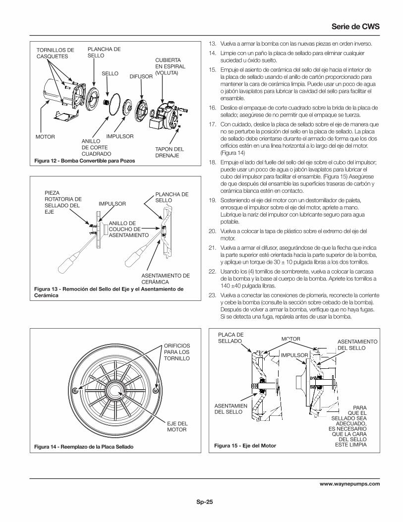
Sp-25
www.waynepumps.com
Serie de CWS
13. Vuelva a armar la bomba con las nuevas piezas en orden inverso.
14. Limpie con un paño la placa de sellado para eliminar cualquier suciedad u óxido suelto.
15. Empuje el asiento de cerámica del sello del eje hacia el interior de la placa de sellado usando el anillo de cartón proporcionado para mantener la cara de cerámica limpia. Puede usar un poco de agua o jabón lavaplatos para lubricar la cavidad del sello para facilitar el ensamble.
16. Deslice el empaque de corte cuadrado sobre la brida de la placa de sellado; asegúrese de no permitir que el empaque se tuerza.
17. Con cuidado, deslice la placa de sellado sobre el eje de manera que no se perturbe la posición del sello en la placa de sellado. La placa de sellado debe orientarse durante el armado de forma que los dos orificios estén en una línea horizontal a lo largo del eje del motor. (Figura 14)
18. Empuje el lado del fuelle del sello del eje sobre el cubo del impulsor; puede usar un poco de agua o jabón lavaplatos para lubricar el cubo del impulsor para facilitar el ensamble. (Figura 15) Asegúrese de que después del ensamble las superficies traseras de carbón y cerámica blanca estén en contacto.
19. Sosteniendo el eje del motor con un destornillador de paleta, enrosque el impulsor sobre el eje del motor, apriete a mano. Lubrique la nariz del impulsor con lubricante seguro para agua potable.
20. Vuelva a colocar la tapa de plástico sobre el extremo del eje del motor.
21. Vuelva a armar el difusor, asegurándose de que la flecha que indica la parte superior esté orientada hacia la parte superior de la bomba, y aplique un torque de 30 ± 10 pulgada libras a los dos tornillos.
22. Usando los (4) tornillos de sombrerete, vuelva a colocar la carcasa de la bomba y la base al cuerpo de la bomba. Apriete los tornillos a 140 ±40 pulgada libras.
23. Vuelva a conectar las conexiones de plomería, reconecte la corriente y cebe la bomba (consulte la sección sobre cebado de la bomba). Después de volver a armar la bomba, verifique que no haya fugas. Si se detecta una fuga, repárela antes de usar la bomba.
Figura 13 - Remoción del Sello del Eje y el Asentamiento de Cerámica
PIEZA ROTATORIA DE SELLADO DEL EJE
ANILLO DE COUCHO DE ASENTAMIENTO
IMPULSOR
PLANCHA DE SELLO
ASENTAMIENTO DE CERÁMICA
Figura 12 - Bomba Convertible para Pozos
TORNILLOS DE CASQUETES
MOTOR
PLANCHA DE SELLO
IMPULSOR
DIFUSOR
CUBIERTA EN ESPIRAL (VOLUTA)
TAPON DEL DRENAJE
Figura 14 - Reemplazo de la Placa Sellado
ORIFICIOS PARA LOS TORNILLO
EJE DEL MOTOR
ASENTAMIENTO DEL SELLO
Figura 15 - Eje del Motor
MOTOR
IMPULSOR
ASENTAMIEN DEL SELLO
PLACA DE SELLADO
PARA QUE EL
SELLADO SEA ADECUADO,
ES NECESARIO QUE LA CARA
DEL SELLO ESTE LIMPIA
ANILLO DE CORTE CUADRADO
SELLO

Sp-26
www.waynepumps.com
Manual de instrucciones de funcionamiento y piezas de repuesto
NOTAS

Sp-27
www.waynepumps.com
Serie de CWS
(A) MANANTIAL:�
Un manantial que emerge�
de la tierra. Ocurre cuando�
el agua en materiales�
permeables está atrapada�
entre materiales �
impermeables tales como �
roca o arcilla.
(B) LAGO, ARROYO o ESTANQUE:�
Agua superficial, que a menos�
que sea tratada, por lo general�
no es apta para consumo �
humano. Puede ser utilizada �
para fines tales como lavado�
o irrigación.
(C) POZO EXCAVA
DO:�
Se excava un hoyo de�
varios pies de diámetro �
hasta una profundidad�
basante superficial. �
Luego se reviste con �
ladrillo, piedra o �
concreto para evitar �
que se derrumbe.
(D) POZO ACCIONADO:�
Se acciona una tubería�
con una pantalla con �
punta en la tierra, por�
debajo de la capa �
freática. La profundidad �
por lo general es menor�
a 15,25 m (50 pies). �
Los diámetros comunes �
fluctúan entre 2,5 cm (1")�
y 5,1 cm (2")
(E) POZO PERFORADO:�
Un hoyo perforado en�
la tierra con maquinaria y�
revestido con tuberías.�
Las profundidades �
fluctúan entre algunos�
pies hasta más de 305 m�
(1000 pies). Los diámetros�
comunes son 5,1 cm (2"), �
7,6 cm (3"), 10,2 cm (4") y �
15,2 cm (6") para pozos �
de agua de uso doméstico. (F) CISTERNA:�
Un tanque subterráneo
construido para recole
agua de lluvias de los
techos. El agua no es�
apta para consumo �
humano.�
�
�
(A) MANANTIAL
(B) LAGO, �
ARROYO, �
ESTANQUE
(C) POZO EXCAVA
DO
(D) POZO �
ACCIONADO
(E) POZO �
PERFORADO�
�
(F) CISTERNA
MATERIAL�
PERMEABLE
ARENA �
ACUIFERA
CAPA FREATICA
�
ESQUISTO
TIERRA �
SUPERFICIAL
ARCILLA
�
Figura 16 - S
uministro
s de A
gua
SU
MIN
IST
RO
S D
E A
GU
A

Sp-28
www.waynepumps.com
Manual de instrucciones de funcionamiento y piezas de repuesto
TABLA DE IDENTIFICACIÓN DE PROBLEMAS
Síntoma Causa(s) Posible(s) Medida Correctiva
La bomba no funciona 1. No hay energía eléctrica 1. Encienda la corriente eléctrica o llame a la compañía de suministro eléctrico
2. El fusible se ha quemado o el interruptor se ha desconectado
2. Cambie el fusible o vuelva a conectar el interruptor de circuito
3. Interruptor de presión fallado 3. Cambie el interruptor4. Desconectado por sobrecarga del motor 4. Deje que se enfríe. La sobrecarga se recalibrará
automáticamente5. Bajo voltaje del circuito 5. Póngase en contacto con un electricista
El motor suena pero no funciona
1. El voltaje de la línea no coincide con el interruptor selector
1. Verifique el selector de voltaje al respaldo del motor
2. El cableado es demasíado pequeño 2. Haga un nuevo cableado. 3. Los daños o la falta de alineamiento dan lugar
que las piezas rotatorías se peguen3. Reemplácelas o llévelas a un taller de servicio para
reparaciones4. Bajo voltaje del circuito 4. Póngase en contacto con un electricista
Desconexión por sobrecarga 1. Bajo voltaje del circuito 1. Póngase en contacto con un electricista2. Los daños o la falta de alineamiento dan lugar
que las piezas rotatorias se peguen2. Lleve el motor a un taller de reparaciones o localice
donde se pegan las piezas y haga las reparaciones3. Alta temperatura en los alredodores 3. Coloque la bomba en una zona sombreada y bien
ventilada4. Ciclos rápidos 4. Vea la sección sobre bombas que funcionan y se
detienon con demasiada frecuencia5. Cableado inadecuado 5. Haga un nuevo cableado
La bomba funciona pero no agua o provee muy poca cantidad
Nota: Verifique el cebado antes de buscar otras causas. Desenrosque el tapón de cebado y observe si hay agua en el orificio de cebado.
1. El nivel de agua está por debajo de la toma de la bomba
1. Baje más el tubo de succión dentro del pozo
2. La válvula de control está demasiado abierta (pozos profundos)
2. Ajuste la válvula de control o repita el procedimiento de cebado
3. Al cebar no se purgó la descarga 3. Abra el grifo y vuelva a cebar4. Hay fuga en la tubería en el lado del pozo donde
está la bomba4. Repare la tubería según sea necesario
5. Está obsstruida la malla de la bomba o el colador de aspiración de entrada
5. Reemplácela según sea necesario
6. Boquilla obstruida (pozos profundos) 6. Jale el eyector de chorro y limpie la obstrucción7. Se ha roto el diafragma del control del volumen
de aire7. Repare o cambie el control del volumen de aire
(Consulte la página 22)8. La válvula de aspiración puede estar obstruida o
atascada en la posición de cerrada8. Límpieia o reemplaceia según sea necesario
9. La bomba no se ha cebado completamente 9. Continúe cebando, haga una pausa cada 5 minutos para que se enfríe el armazón de la bomba. Vuelva a llenar la bomba según sea necesario
10. La válvula de control está completamente cerrada (pozos profundos)
10. Ajuste la válvula de control siguiendo el procedimiento de cebado para pozos profundos (consulte la página 7).
11. Nivel de agua por debajo de lo requerido para aspirar
11. Seleccione el ensamblado de la bomba y/o del eyector de chor ro que correspondan
12. Tubería de tamaño menor que el requerido 12. Reemplace según sea necesario13. Pozo gaseoso 13. Instale un deflector en la entrada a la bomba para evitar
que los gases entren al sistema14. Venturi distorsionado 14. Inspecciónelo y reemplácelo15. Eyector de chorro inadecuado para la aplicación 15. Adquiera un eyector de chor ro que encaje en su
sistema cuando esté reemplazando una bomba de otra marca
16. Bomba de tamaño muy pequeño 16. Aumente el caballaje de la bomba17. La bomba forma vacios parclales (suena como si
estuviera bombeando cascajo)17. Aumente el diámetro de la tubería de succion o
disminuya la fricción en la tubería18. Bajo voltaje del circuito 18. Póngase en contacto con un electricista

Sp-29
www.waynepumps.com
Serie de CWS
TABLA DE IDENTIFICACIÓN DE PROBLEMAS (CONTINÚA)
Síntoma Causa(s) Posible(s) Medida Correctiva
La bomba se prende y apaga continuamente
1. Tanque inundado (Convencional) 1. Vea, “Movimiento de agua se hace lento: convencional”, página 24
2. La tubería del control del volumen de aire está doblada u obtruida
2. Límpiela o reemplácela según sea necesario
3. Control de volumen de aire conectado a la salida incorrecta de la bomba
3. Mueva a la apertura correcta de la bomba
4. Precarga de tanqueincorrecta (Tanque precargado)
4. Agregue o quite aire cuanto sea necesario
5. Diafragma o bolsa rota (Tanque precargado) 5. Cambie el tanque6. Fuga enla tubería de la casa 6. Localie y repare la fuga7. Válvula de pie o válvula de retención atascada en
posición abierta7. Retire y reemplace
8. El motor se desconecta por sobrecarga 8. Vea la sección sobre desconexiones por sobrecarga9. Interruptor de presión fallado 9. Cambie el interruptor

Sp-30
www.waynepumps.com
Manual de instrucciones de funcionamiento y piezas de repuesto
Para Ordenar Repuestos o Asistencia Técnica, Sírvase Llamar al Distribuidor Más Cercano a Su DomicilioSirvase darnos la siguiente información: Dirija toda la correspondencia a:
- Número del modelo Wayne Water Systems - Código impreso 101 Production Drive - Descripción y número del repuesto según la lista de repuestos Harrison, OH 45030 U.S.A.
LISTA DE PARTES DE REPARACIÓN
No. de Ref.
Número de Parte para Modelos:
Descripción CWS50-1/2 HP CWS75-3/4 HP CWS100-1 HP Ctd.
1 (2) empaques de anillo cuadrado, impulsor, difusor de bomba de inyector y ensamble del sello del eje
64046-WYN1 64047-WYN1 64047-WYN1 1
1

Sp-31
www.waynepumps.com
Série CWS
Sp-31
www.waynepumps.com
RENDIMIENTO
No. de Modelo Motor CP
Succión de Elevación (metros)
Presión de Descarga bar
2,07 2,76 3,45
Entrega en Litros por Hora (LPH)
CWS50 1/2
0
3,05
6,10
9,14
12,19
4091
3546
3137
2591
2073
3000
2591
2046
1582
1227
1855
1364
955
682
273
CWS75 3/4
0
3,05
6,10
9,14
12,19
4501
4119
3519
2864
2319
3546
2864
2319
1855
1391
2100
1500
1227
982
709
CWS100 1
0
3,05
6,10
9,14
12,19
4801
4310
3846
3410
2919
3819
3410
2919
2400
1746
2673
2018
1500
1200
1064
Diámetro del Charro
Modelo de Bomba No.
Ensamblado del Chorro No.
Distancia Vertical al Nivel de Bombeo (En Metres)
9,1 12,2 15,2 18,3 21,4 24,4 27,4 30,5
Entrega en Litros por Hora (LPH)
5,08 cm
CWS50
CWS50
56319
55462
2347 2233 1893
1514 1268 984
CWS75
CWS75
56322
55462
3179 2801 2328
1476 1363 1098
CWS100
CWS100
56322
58319
3369 2952 2460
1968 1590 1249
10,16 cm
CWS50
CWS50
CWS50
56324
56317
55465
3407 2839
2612 2195 2044
1571
1476
1268 1041 795
CWS75
CWS75
56324
55465
3407 3028 2555
1779 1590 1287 1060 757
CWS100
CWS100
CWS100
56324
56317
55465
3596 3179 2672
2214 1855 1476
1192 871

Sp-32
www.waynepumps.com
Manual de instrucciones de funcionamiento y piezas de repuesto
Garantie Limitée
Pendant trois ans à compter de la date d’achat, Wayne Water Systems ("Wayne") va réparer ou remplacer, à sa discrétion, pour l’acheteur original toute pièce ou pièces de ces Pompes De Puisard ou Pompes À Eau ("Produit") déterminées défectueuses, par Wayne, soit pour les matériaux ou la fabrication. Veuillez appeler Wayne (800-237-0987) pour des instructions ou contacter votre marchand. S’assurer d’avoir, à sa disposition, le numéro du modèle afin d’effectuer cette garantie. Les frais de transport des Produits ou pièces soumis pour leur réparation ou leur remplacement sont la responsabilité de l’acheteur.
Cette Garantie Limitée ne couvre pas les Produits qui se sont fait endommagés suite à un accident, une utilisation abusive, un mauvais usage, de la négligence, une mauvaise installation, un mauvais entretien, ou une utilisation non conforme aux instructions écrites de Wayne
IL N’EXISTE AUCUNE AUTRE GARANTIE OU DÉCLARATION. LES GARANTIES EXPRESSES, Y COMPRIS CELLES DE COMMERCIALISABILITÉ ET D’ADAPTATION À UNE FONCTION PARTICULIÈRE, SONT LIMITÉES À TROIS ANS À COMPTER DE LA DATE D’ACHAT. CECI EST LE SEUL RECOURS EXCLUSIF ET TOUTE AUTRE RESPONSABILITÉ POUR TOUT AUTRE DOMMAGE QUELCONQUE INDIRECT OU DÉPENSES QUELCONQUES SONT EXCLUS.
Certaines Provinces n’autorisent pas de limites de durée pour les garanties implicites, ni l’exclusion ni la limite des dommages fortuits ou indirects. Les limites précédentes peuvent donc ne pas s’appliquer. Cette garantie limitée donne à l’acheteur, des droits légaux précis, et vous pouvez avoir d'autres droits légaux qui varient d’une Province ou d’un État à l’autre.
En aucun cas, soit par suite d’une rupture de contrat de garantie, acte dommageable (y compris la négligence) ou autrement, ni Wayne ni ses fournisseurs ne seront tenus responsables pour aucun dommage spécial, indirect ou pénal, y compris, mais sans s'y limiter la perte de profits ou recettes, la perte d’usage des produits ou n’importe quel équipement associé, dommage à l’équipement associé, coût de capital, coût de produits remplaçants, aménagements, services ou capacité de remplacement, coût de temps que le produit n’est pas en service, ou réclamation des clients de l’acheteur pour ces dommages.
Vous DEVEZ garder votre reçu d’achat avec ce bulletin. Il est NÉCESSAIRE d’envoyer une copie du reçu d’achat avec le produit ou la correspondance afin d’effectuer une réclamation sous la garantie. Veuillez appeler Wayne (800-237-0987) pour l’autorisation et les instructions concernant le renvoi.
NE PAS ENVOYER, PAR LA POSTE, CE BULLETIN À WAYNE. Utiliser ce bulletin seulement pour vos archives.
Nº DU MODÈLE _____________________ Nº DE SÉRIE ________________________ DATE D’INSTALLATION _____________________
FIXER VOTRE FACTURE ICI