Conventional Completion Tools Technical Catalogue · The CWX-10 packer provides time saving...
68
TMK Completions Conventional Completion Tools Technical Catalogue COMPLETIONS
Transcript of Conventional Completion Tools Technical Catalogue · The CWX-10 packer provides time saving...
TMK Completions Conventional Completion Tools
Technical Catalogue
COMPLETIONS
2
TMK Completions
TMK Completions Headquarters
10120 Houston Oaks DriveHouston, TX 77064Tel: +1 281 949 1023Fax: +1 281 445 [email protected]
TMK Completions Canada
300, 521-3rd Ave. SWCalgary, AB T2P 3T3Tel: +1 403 264 4577Fax: +1 403 264 [email protected]
3
Table of Contents
RETRIEVABLE PACKERS 4
PERMANENT PACKERS 20
PACKER ACCESSORIES 28
RETRIEVABLE BRIDGE PLUGS 30
PERMANENT BRIDGE PLUG 33
CEMENT RETAINERS 40
LINER HANGERS 42
OPEN HOLE PACKERS 44
OPEN HOLE STRADDLE SYSTEM 46
THRU TUBING RESETTABLE INFLATE SYSTEM 50
SELECTIVE ACID TOOL ASSEMBLY 52
PRODUCTION ACCESSORIES 53
COIL ACCESSORIES 63
COIL PACKERS 65
4
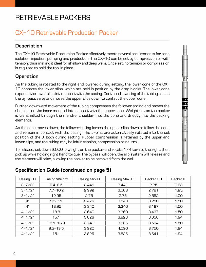
CX-10 Retrievable Production Packer
Description
The CX-10 Retrievable Production Packer effectively meets several requirements for zone isolation, injection, pumping and production. The CX-10 can be set by compression or with tension, thus making it ideal for shallow and deep wells. Once set, no tension or compression is required to hold the tool in place.
Operation
As the tubing is rotated to the right and lowered during setting, the lower cone of the CX-10 contacts the lower slips, which are held in position by the drag blocks. The lower cone expands the lower slips into contact with the casing. Continued lowering of the tubing closes the by-pass valve and moves the upper slips down to contact the upper cone.
Further downward movement of the tubing compresses the follower spring and moves the shoulder on the inner mandrel into contact with the upper cone. Weight set on the packer is transmitted through the mandrel shoulder, into the cone and directly into the packing elements.
As the cone moves down, the follower spring forces the upper slips down to follow the cone and remain in contact with the casing. The J-pins are automatically rotated into the set position of the J-body during setting. Rubber compression is retained by the upper and lower slips, and the tubing may be left in tension, compression or neutral.
To release, set down 2,000 lb weight on the packer and rotate 1/4 turn to the right, then pick up while holding right hand torque. The bypass will open, the slip system will release and the element will relax, allowing the packer to be removed from the well.
Casing OD Casing Weight Casing Min ID Casing Max. ID Packer OD Packer ID
2-7/8” 6.4-6.5 2.441 2.441 2.25 0.63
3-1/2” 7.7-10.2 2.992 3.068 2.781 1.25
3-1/2” 12.95 2.75 2.75 2.562 1.00
4” 9.5-11 3.476 3.548 3.250 1.50
4” 12.95 3.340 3.340 3.187 1.50
4-1/2” 18.8 3.640 3.360 3.437 1.50
4-1/2” 15.1 3.826 3.826 3.656 1.94
4-1/2” 15.1-16.9 3.740 3.826 3.594 1.50
4-1/2” 9.5-13.5 3.920 4.090 3.750 1.94
4-1/2” 15.1 3.826 3.826 3.641 1.94
Specification Guide (continued on page 5)
RETRIEVABLE PACKERS
5
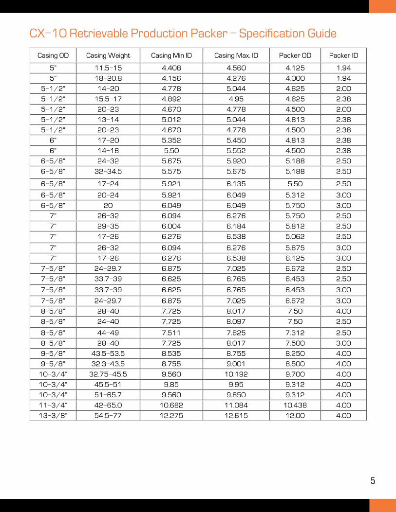
CX-10 Retrievable Production Packer - Specification Guide
Casing OD Casing Weight Casing Min ID Casing Max. ID Packer OD Packer ID
5” 11.5-15 4.408 4.560 4.125 1.94
5” 18-20.8 4.156 4.276 4.000 1.94
5-1/2” 14-20 4.778 5.044 4.625 2.00
5-1/2” 15.5-17 4.892 4.95 4.625 2.38
5-1/2” 20-23 4.670 4.778 4.500 2.00
5-1/2” 13-14 5.012 5.044 4.813 2.38
5-1/2” 20-23 4.670 4.778 4.500 2.38
6” 17-20 5.352 5.450 4.813 2.38
6” 14-16 5.50 5.552 4.500 2.38
6-5/8” 24-32 5.675 5.920 5.188 2.50
6-5/8” 32-34.5 5.575 5.675 5.188 2.50
6-5/8” 17-24 5.921 6.135 5.50 2.50
6-5/8” 20-24 5.921 6.049 5.312 3.00
6-5/8” 20 6.049 6.049 5.750 3.00
7” 26-32 6.094 6.276 5.750 2.50
7” 29-35 6.004 6.184 5.812 2.50
7” 17-26 6.276 6.538 5.062 2.50
7” 26-32 6.094 6.276 5.875 3.00
7” 17-26 6.276 6.538 6.125 3.00
7-5/8” 24-29.7 6.875 7.025 6.672 2.50
7-5/8” 33.7-39 6.625 6.765 6.453 2.50
7-5/8” 33.7-39 6.625 6.765 6.453 3.00
7-5/8” 24-29.7 6.875 7.025 6.672 3.00
8-5/8” 28-40 7.725 8.017 7.50 4.00
8-5/8” 24-40 7.725 8.097 7.50 2.50
8-5/8” 44-49 7.511 7.625 7.312 2.50
8-5/8” 28-40 7.725 8.017 7.500 3.00
9-5/8” 43.5-53.5 8.535 8.755 8.250 4.00
9-5/8” 32.3-43.5 8.755 9.001 8.500 4.00
10-3/4” 32.75-45.5 9.560 10.192 9.700 4.00
10-3/4” 45.5-51 9.85 9.95 9.312 4.00
10-3/4” 51-65.7 9.560 9.850 9.312 4.00
11-3/4” 42-65.0 10.682 11.084 10.438 4.00
13-3/8” 54.5-77 12.275 12.615 12.00 4.00
6
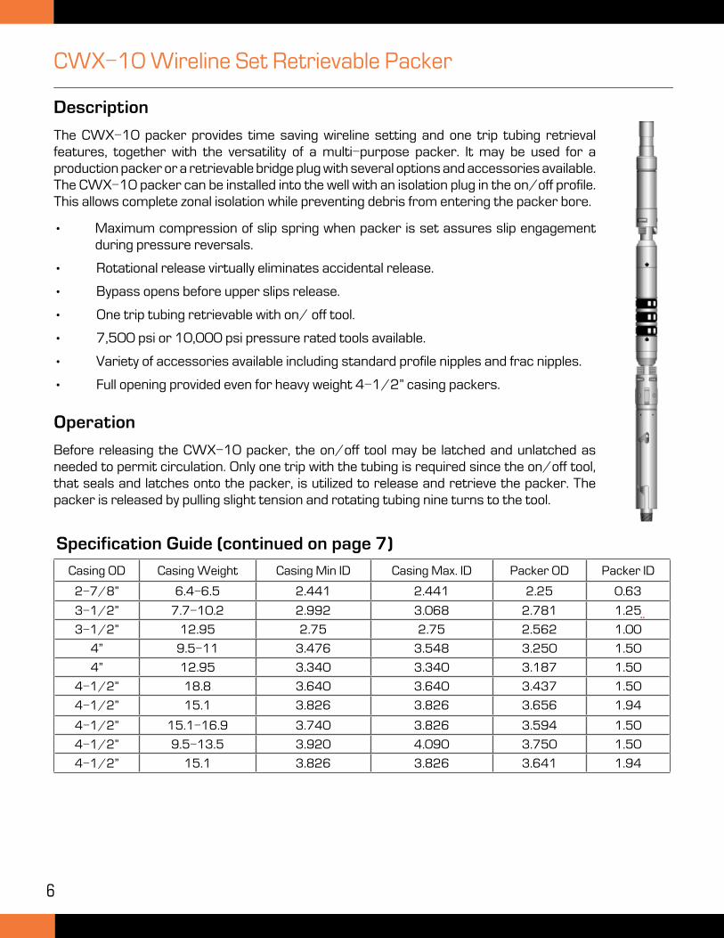
CWX-10 Wireline Set Retrievable Packer
Description
The CWX-10 packer provides time saving wireline setting and one trip tubing retrieval features, together with the versatility of a multi-purpose packer. It may be used for a production packer or a retrievable bridge plug with several options and accessories available. The CWX-10 packer can be installed into the well with an isolation plug in the on/off profile. This allows complete zonal isolation while preventing debris from entering the packer bore.
• Maximum compression of slip spring when packer is set assures slip engagement during pressure reversals.
• Rotational release virtually eliminates accidental release.
• Bypass opens before upper slips release.
• One trip tubing retrievable with on/ off tool.
• 7,500 psi or 10,000 psi pressure rated tools available.
• Variety of accessories available including standard profile nipples and frac nipples.
• Full opening provided even for heavy weight 4-1/2” casing packers.
Operation
Before releasing the CWX-10 packer, the on/off tool may be latched and unlatched as needed to permit circulation. Only one trip with the tubing is required since the on/off tool, that seals and latches onto the packer, is utilized to release and retrieve the packer. The packer is released by pulling slight tension and rotating tubing nine turns to the tool.
Casing OD Casing Weight Casing Min ID Casing Max. ID Packer OD Packer ID
2-7/8” 6.4-6.5 2.441 2.441 2.25 0.63
3-1/2” 7.7-10.2 2.992 3.068 2.781 1.25
3-1/2” 12.95 2.75 2.75 2.562 1.00
4” 9.5-11 3.476 3.548 3.250 1.50
4” 12.95 3.340 3.340 3.187 1.50
4-1/2” 18.8 3.640 3.640 3.437 1.50
4-1/2” 15.1 3.826 3.826 3.656 1.94
4-1/2” 15.1-16.9 3.740 3.826 3.594 1.50
4-1/2” 9.5-13.5 3.920 4.090 3.750 1.50
4-1/2” 15.1 3.826 3.826 3.641 1.94
Specification Guide (continued on page 7)
7
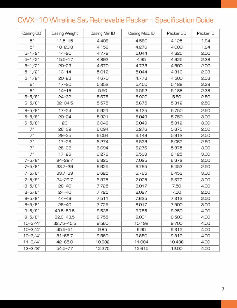
CWX-10 Wireline Set Retrievable Packer - Specification Guide
Casing OD Casing Weight Casing Min ID Casing Max. ID Packer OD Packer ID
5” 11.5-15 4.408 4.560 4.125 1.94
5” 18-20.8 4.156 4.276 4.000 1.94
5-1/2” 14-20 4.778 5.044 4.625 2.00
5-1/2” 15.5-17 4.892 4.95 4.625 2.38
5-1/2” 20-23 4.670 4.778 4.500 2.00
5-1/2” 13-14 5.012 5.044 4.813 2.38
5-1/2” 20-23 4.670 4.778 4.500 2.38
6” 17-20 5.352 5.450 5.188 2.38
6” 14-16 5.50 5.552 5.188 2.38
6-5/8” 24-32 5.675 5.920 5.50 2.50
6-5/8” 32-34.5 5.575 5.675 5.312 2.50
6-5/8” 17-24 5.921 6.135 5.750 2.50
6-5/8” 20-24 5.921 6.049 5.750 3.00
6-5/8” 20 6.049 6.049 5.812 3.00
7” 26-32 6.094 6.276 5.875 2.50
7” 29-35 6.004 6.148 5.812 2.50
7” 17-26 6.274 6.538 6.062 2.50
7” 26-32 6.094 6.276 5.875 3.00
7” 17-26 6.276 6.538 6.125 3.00
7-5/8” 24-29.7 6.825 7.025 6.672 2.50
7-5/8” 33.7-39 6.625 6.765 6.453 2.50
7-5/8” 33.7-39 6.625 6.765 6.453 3.00
7-5/8” 24-29.7 6.875 7.025 6.672 3.00
8-5/8” 28-40 7.725 8.017 7.50 4.00
8-5/8” 24-40 7.725 8.097 7.50 2.50
8-5/8” 44-49 7.511 7.625 7.312 2.50
8-5/8” 28-40 7.725 8.017 7.500 3.00
9-5/8” 43.5-53.5 8.535 8.755 8.250 4.00
9-5/8” 32.3-43.5 8.755 9.001 8.500 4.00
10-3/4” 32.75-45.5 9.560 10.192 9.700 4.00
10-3/4” 45.5-51 9.85 9.95 9.312 4.00
10-3/4” 51-65.7 9.560 9.850 9.312 4.00
11-3/4” 42-65.0 10.682 11.084 10.438 4.00
13-3/8” 54.5-77 12.275 12.615 12.00 4.00
8
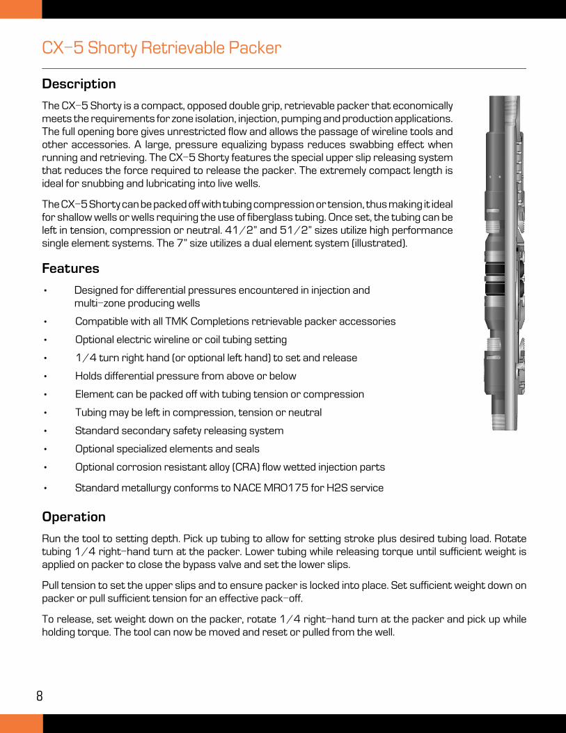
CX-5 Shorty Retrievable Packer
Description
The CX-5 Shorty is a compact, opposed double grip, retrievable packer that economically meets the requirements for zone isolation, injection, pumping and production applications. The full opening bore gives unrestricted flow and allows the passage of wireline tools and other accessories. A large, pressure equalizing bypass reduces swabbing effect when running and retrieving. The CX-5 Shorty features the special upper slip releasing system that reduces the force required to release the packer. The extremely compact length is ideal for snubbing and lubricating into live wells.
The CX-5 Shorty can be packed off with tubing compression or tension, thus making it ideal for shallow wells or wells requiring the use of fiberglass tubing. Once set, the tubing can be left in tension, compression or neutral. 41/2” and 51/2” sizes utilize high performance single element systems. The 7” size utilizes a dual element system (illustrated).
Features
• Designed for differential pressures encountered in injection and multi-zone producing wells
• Compatible with all TMK Completions retrievable packer accessories
• Optional electric wireline or coil tubing setting
• 1/4 turn right hand (or optional left hand) to set and release
• Holds differential pressure from above or below
• Element can be packed off with tubing tension or compression
• Tubing may be left in compression, tension or neutral
• Standard secondary safety releasing system
• Optional specialized elements and seals
• Optional corrosion resistant alloy (CRA) flow wetted injection parts
• Standard metallurgy conforms to NACE MR0175 for H2S service
Operation
Run the tool to setting depth. Pick up tubing to allow for setting stroke plus desired tubing load. Rotate tubing 1/4 right-hand turn at the packer. Lower tubing while releasing torque until sufficient weight is applied on packer to close the bypass valve and set the lower slips.
Pull tension to set the upper slips and to ensure packer is locked into place. Set sufficient weight down on packer or pull sufficient tension for an effective pack-off.
To release, set weight down on the packer, rotate 1/4 right-hand turn at the packer and pick up while holding torque. The tool can now be moved and reset or pulled from the well.
9
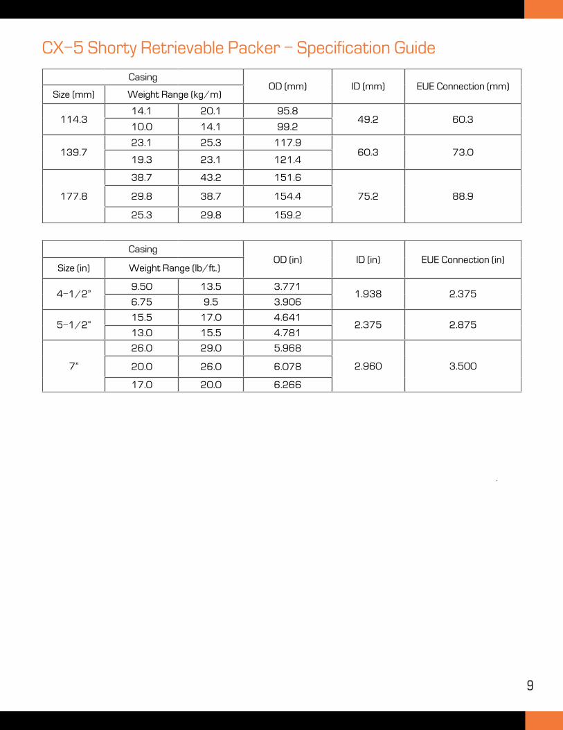
CX-5 Shorty Retrievable Packer - Specification Guide
CasingOD (mm) ID (mm) EUE Connection (mm)
Size (mm) Weight Range (kg/m)
114.314.1 20.1 95.8
49.2 60.310.0 14.1 99.2
139.723.1 25.3 117.9
60.3 73.019.3 23.1 121.4
177.8
38.7 43.2 151.6
75.2 88.929.8 38.7 154.4
25.3 29.8 159.2
CasingOD (in) ID (in) EUE Connection (in)
Size (in) Weight Range (lb/ft.)
4-1/2”9.50 13.5 3.771
1.938 2.3756.75 9.5 3.906
5-1/2”15.5 17.0 4.641
2.375 2.87513.0 15.5 4.781
7”
26.0 29.0 5.968
2.960 3.50020.0 26.0 6.078
17.0 20.0 6.266
10
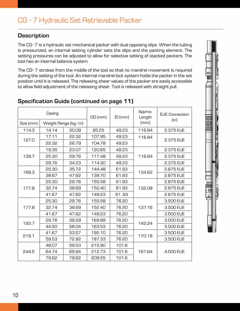
CG -7 Hydraulic Set Retrievable Packer
Description
The CG-7 is a hydraulic set mechanical packer with dual opposing slips. When the tubing is pressurized, an internal setting cylinder sets the slips and the packing element. The setting pressures can be adjusted to allow for selective setting of stacked packers. The tool has an internal balance system
The CG-7 strokes from the middle of the tool so that no mandrel movement is required during the setting of the tool. An internal mandrel lock system holds the packer in the set position until it is released. The releasing shear values of the packer are easily accessible to allow field adjustment of the releasing shear. Tool is released with straight pull.
CasingOD (mm) ID (mm)
Approx. Length (mm)
EUE Connection (in)
Size (mm) Weight Range (kg/m)
114.3 14.14 20.09 95.25 49.23 116.84 2.375 EUE
127.017.11 22.32 107.95 49.23 116.84
2.375 EUE22.32 26.79 104.78 49.23
139.7
19.35 23.07 120.65 49.23
116.84
2.375 EUE
25.30 29.76 117.48 49.23 2.375 EUE
29.76 34.23 114.30 49.23 2.375 EUE
168.325.30 35.72 144.48 61.93
134.622.875 EUE
38.67 47.62 139.70 61.93 2.875 EUE
177.8
25.30 29.76 155.58 61.93
132.08
2.875 EUE
32.74 38.69 152.40 61.93 2.875 EUE
41.67 47.62 149.23 61 .93 2.875 EUE
177.8
25.30 29.76 155.58 76.20
137.16
3.500 EUE
32.74 38.69 152.40 76.20 3.500 EUE
41.67 47.62 149.23 76.20 3.500 EUE
193.729.76 39.29 169.88 76.20
142.243.500 EUE
44.20 58.04 163.53 76.20 3.500 EUE
219.141.67 53.57 192.10 76.20
170.183.500 EUE
59.53 72.92 187.33 76.20 3.500 EUE
244.5
48.07 59.53 215.90 101.6
167.64 4.500 EUE64.74 69.94 212.73 101.6
79.62 79.62 209.55 101.6
Specification Guide (continued on page 11)
11
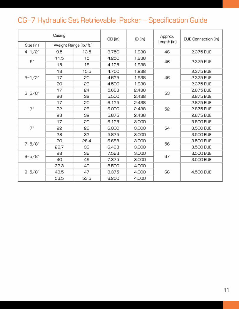
CG-7 Hydraulic Set Retrievable Packer - Specification Guide
CasingOD (in) ID (in)
Approx. Length (in)
EUE Connection (in)
Size (in) Weight Range (lb/ft.)
4-1/2” 9.5 13.5 3.750 1.938 46 2.375 EUE
5”11.5 15 4.250 1.938
46 2.375 EUE15 18 4.125 1.938
5-1/2”
13 15.5 4.750 1.938
46
2.375 EUE
17 20 4.625 1.938 2.375 EUE
20 23 4.500 1.938 2.375 EUE
6-5/8”17 24 5.688 2.438
532.875 EUE
26 32 5.500 2.438 2.875 EUE
7”
17 20 6.125 2.438
52
2.875 EUE
22 26 6.000 2.438 2.875 EUE
28 32 5.875 2.438 2.875 EUE
7”
17 20 6.125 3.000
54
3.500 EUE
22 26 6.000 3.000 3.500 EUE
28 32 5.875 3.000 3.500 EUE
7-5/8”20 26.4 6.688 3.000
563.500 EUE
29.7 39 6.438 3.000 3.500 EUE
8-5/8”28 36 7.563 3.000
673.500 EUE
40 49 7.375 3.000 3.500 EUE
9-5/8”
32.3 40 8.500 4.000
66 4.500 EUE43.5 47 8.375 4.000
53.5 53.5 8.250 4.000
12
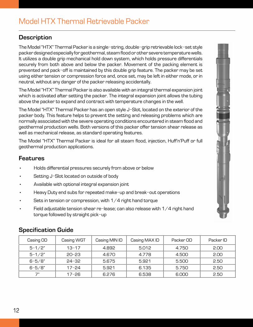
Model HTX Thermal Retrievable Packer
Description
The Model “HTX” Thermal Packer is a single-string, double-grip retrievable lock-set style packer designed especially for geothermal, steam flood or other severe temperature wells. It utilizes a double grip mechanical hold down system, which holds pressure differentials securely from both above and below the packer. Movement of the packing element is prevented and pack-off is maintained by this double grip feature. The packer may be set using either tension or compression force and, once set, may be left in either mode, or in neutral, without any danger of the packer releasing accidentally.
The Model “HTX” Thermal Packer is also available with an integral thermal expansion joint which is activated after setting the packer. The integral expansion joint allows the tubing above the packer to expand and contract with temperature changes in the well.
The Model “HTX” Thermal Packer has an open style J-Slot, located on the exterior of the packer body. This feature helps to prevent the setting and releasing problems which are normally associated with the severe operating conditions encountered in steam flood and geothermal production wells. Both versions of this packer offer tension shear release as well as mechanical release, as standard operating features.
The Model “HTX” Thermal Packer is ideal for all steam flood, injection, Huff’n’Puff or full geothermal production applications.
Features
• Holds differential pressures securely from above or below
• Setting J-Slot located on outside of body
• Available with optional integral expansion joint
• Heavy Duty end subs for repeated make-up and break-out operations
• Sets in tension or compression, with 1/4 right hand torque
• Field adjustable tension shear re-lease; can also release with 1/4 right hand torque followed by straight pick-up
Casing OD Casing WGT Casing MIN ID Casing MAX ID Packer OD Packer ID
5-1/2” 13-17 4.892 5.012 4.750 2.00
5-1/2” 20-23 4.670 4.778 4.500 2.00
6-5/8” 24-32 5.675 5.921 5.500 2.50
6-5/8” 17-24 5.921 6.135 5.750 2.50
7” 17-26 6.276 6.538 6.000 2.50
Specification Guide
13
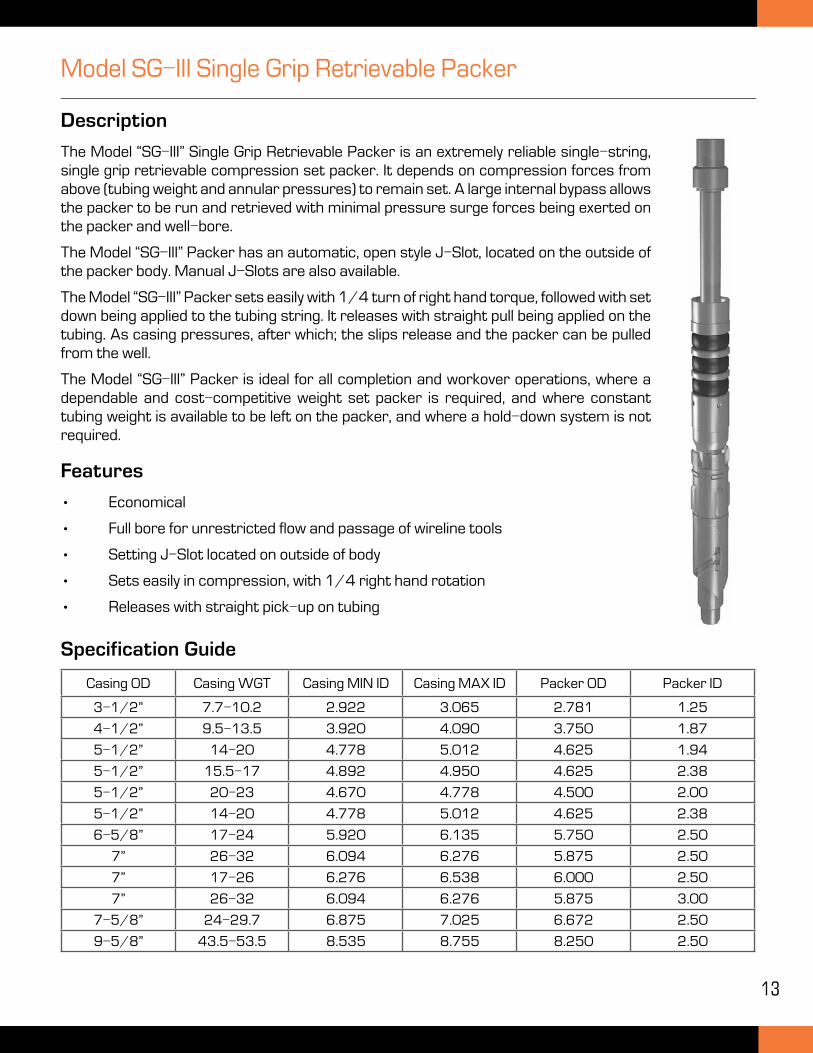
Model SG-III Single Grip Retrievable Packer
Description
The Model “SG-III” Single Grip Retrievable Packer is an extremely reliable single-string, single grip retrievable compression set packer. It depends on compression forces from above (tubing weight and annular pressures) to remain set. A large internal bypass allows the packer to be run and retrieved with minimal pressure surge forces being exerted on the packer and well-bore.
The Model “SG-III” Packer has an automatic, open style J-Slot, located on the outside of the packer body. Manual J-Slots are also available.
The Model “SG-III” Packer sets easily with 1/4 turn of right hand torque, followed with set down being applied to the tubing string. It releases with straight pull being applied on the tubing. As casing pressures, after which; the slips release and the packer can be pulled from the well.
The Model “SG-III” Packer is ideal for all completion and workover operations, where a dependable and cost-competitive weight set packer is required, and where constant tubing weight is available to be left on the packer, and where a hold-down system is not required.
Features
• Economical
• Full bore for unrestricted flow and passage of wireline tools
• Setting J-Slot located on outside of body
• Sets easily in compression, with 1/4 right hand rotation
• Releases with straight pick-up on tubing
Specification Guide
Casing OD Casing WGT Casing MIN ID Casing MAX ID Packer OD Packer ID
3-1/2” 7.7-10.2 2.922 3.065 2.781 1.25
4-1/2” 9.5-13.5 3.920 4.090 3.750 1.87
5-1/2” 14-20 4.778 5.012 4.625 1.94
5-1/2” 15.5-17 4.892 4.950 4.625 2.38
5-1/2” 20-23 4.670 4.778 4.500 2.00
5-1/2” 14-20 4.778 5.012 4.625 2.38
6-5/8” 17-24 5.920 6.135 5.750 2.50
7” 26-32 6.094 6.276 5.875 2.50
7” 17-26 6.276 6.538 6.000 2.50
7” 26-32 6.094 6.276 5.875 3.00
7-5/8” 24-29.7 6.875 7.025 6.672 2.50
9-5/8” 43.5-53.5 8.535 8.755 8.250 2.50
14
HD Retrievable Packer
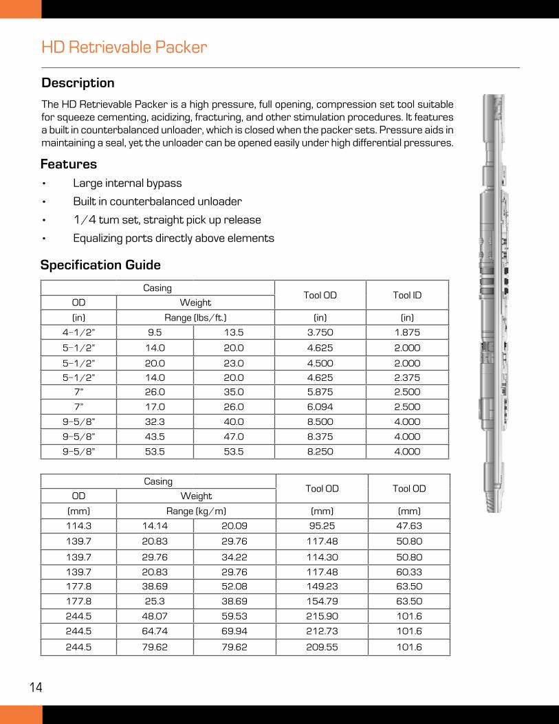
Description
The HD Retrievable Packer is a high pressure, full opening, compression set tool suitable for squeeze cementing, acidizing, fracturing, and other stimulation procedures. It features a built in counterbalanced unloader, which is closed when the packer sets. Pressure aids in maintaining a seal, yet the unloader can be opened easily under high differential pressures.
Features
• Large internal bypass
• Built in counterbalanced unloader
• 1/4 tum set, straight pick up release
• Equalizing ports directly above elements
Specification Guide
CasingTool OD Tool ID
OD Weight
(in) Range (lbs/ft.) (in) (in)
4-1/2” 9.5 13.5 3.750 1.875
5-1/2” 14.0 20.0 4.625 2.000
5-1/2” 20.0 23.0 4.500 2.000
5-1/2” 14.0 20.0 4.625 2.375
7” 26.0 35.0 5.875 2.500
7” 17.0 26.0 6.094 2.500
9-5/8” 32.3 40.0 8.500 4.000
9-5/8” 43.5 47.0 8.375 4.000
9-5/8” 53.5 53.5 8.250 4.000
CasingTool OD Tool OD
OD Weight
(mm) Range (kg/m) (mm) (mm)
114.3 14.14 20.09 95.25 47.63
139.7 20.83 29.76 117.48 50.80
139.7 29.76 34.22 114.30 50.80
139.7 20.83 29.76 117.48 60.33
177.8 38.69 52.08 149.23 63.50
177.8 25.3 38.69 154.79 63.50
244.5 48.07 59.53 215.90 101.6
244.5 64.74 69.94 212.73 101.6
244.5 79.62 79.62 209.55 101.6
15
CDG Retrievable Casing Patch
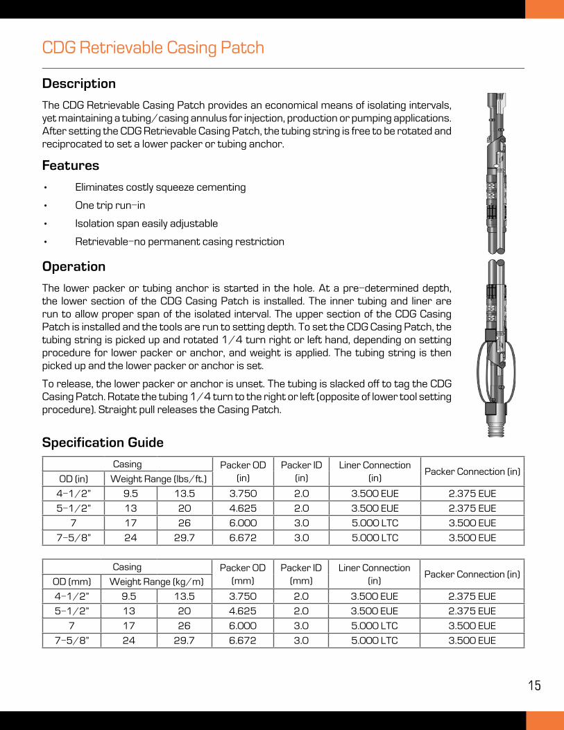
Description
The CDG Retrievable Casing Patch provides an economical means of isolating intervals, yet maintaining a tubing/casing annulus for injection, production or pumping applications. After setting the CDG Retrievable Casing Patch, the tubing string is free to be rotated and reciprocated to set a lower packer or tubing anchor.
Features
• Eliminates costly squeeze cementing
• One trip run-in
• Isolation span easily adjustable
• Retrievable-no permanent casing restriction
Specification Guide
Operation
The lower packer or tubing anchor is started in the hole. At a pre-determined depth, the lower section of the CDG Casing Patch is installed. The inner tubing and liner are run to allow proper span of the isolated interval. The upper section of the CDG Casing Patch is installed and the tools are run to setting depth. To set the CDG Casing Patch, the tubing string is picked up and rotated 1/4 turn right or left hand, depending on setting procedure for lower packer or anchor, and weight is applied. The tubing string is then picked up and the lower packer or anchor is set.
To release, the lower packer or anchor is unset. The tubing is slacked off to tag the CDG Casing Patch. Rotate the tubing 1/4 turn to the right or left (opposite of lower tool setting procedure). Straight pull releases the Casing Patch.
Casing Packer OD (in)
Packer ID(in)
Liner Connection (in)
Packer Connection (in)OD (in) Weight Range (lbs/ft.)
4-1/2” 9.5 13.5 3.750 2.0 3.500 EUE 2.375 EUE
5-1/2” 13 20 4.625 2.0 3.500 EUE 2.375 EUE
7 17 26 6.000 3.0 5.000 LTC 3.500 EUE
7-5/8” 24 29.7 6.672 3.0 5.000 LTC 3.500 EUE
Casing Packer OD (mm)
Packer ID(mm)
Liner Connection (in)
Packer Connection (in)OD (mm) Weight Range (kg/m)
4-1/2” 9.5 13.5 3.750 2.0 3.500 EUE 2.375 EUE
5-1/2” 13 20 4.625 2.0 3.500 EUE 2.375 EUE
7 17 26 6.000 3.0 5.000 LTC 3.500 EUE
7-5/8” 24 29.7 6.672 3.0 5.000 LTC 3.500 EUE
16
Hydraulic Set Retrievable Sealbore Packer
Description
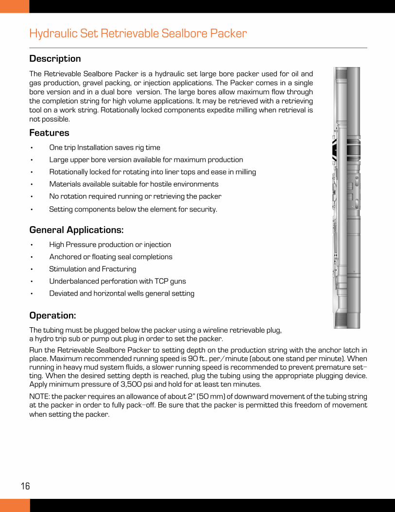
The Retrievable Sealbore Packer is a hydraulic set large bore packer used for oil and gas production, gravel packing, or injection applications. The Packer comes in a single bore version and in a dual bore version. The large bores allow maximum flow through the completion string for high volume applications. It may be retrieved with a retrieving tool on a work string. Rotationally locked components expedite milling when retrieval is not possible.
Features
• One trip Installation saves rig time
• Large upper bore version available for maximum production
• Rotationally locked for rotating into liner tops and ease in milling
• Materials available suitable for hostile environments
• No rotation required running or retrieving the packer
• Setting components below the element for security.
General Applications:
• High Pressure production or injection
• Anchored or floating seal completions
• Stimulation and Fracturing
• Underbalanced perforation with TCP guns
• Deviated and horizontal wells general setting
Operation:
The tubing must be plugged below the packer using a wireline retrievable plug, a hydro trip sub or pump out plug in order to set the packer.
Run the Retrievable Sealbore Packer to setting depth on the production string with the anchor latch in place. Maximum recommended running speed is 90 ft.. per/minute (about one stand per minute). When running in heavy mud system fluids, a slower running speed is recommended to prevent premature set-ting. When the desired setting depth is reached, plug the tubing using the appropriate plugging device. Apply minimum pressure of 3,500 psi and hold for at least ten minutes.
NOTE: the packer requires an allowance of about 2” (50 mm) of downward movement of the tubing string at the packer in order to fully pack-off. Be sure that the packer is permitted this freedom of movement when setting the packer.
17
Hydraulic Set Retrievable Sealbore Packer
Releasing Procedure
Retrieve the production string and anchor latch form the packer. Run the retrieving tool on a work string and apply set down force of approximately 2,000-3,000 lbs when the packer is reached. The latch on the retrieving tool will engage with the top of the packer.
At this point, the releasing collet is positioned directly below the support ring of the packer.
Pick-up at least 10,000 lbs over string weight to part the shear screws in to support ring and shift it upward thus releasing the packer. If the support ring does not shear out easily, then there is a built in bumper sub in the retrieving tool. By bumping upward, either the support ring will shear or the shear ring in the retrieving tool will release. This is a safety release device, which will enable the retrieving tool to be rotated free of the packer if the packer will not release. If it is necessary to use the emergency release from the packer, pull tension of approximately 2,000-3,000 lbs and rotate to the right at least 8 turns at the packer to release the retrieving tools form the packer. The shear value of the release ring is adjustable and should be considered prior to running the retrieving tool.
Specification Guide
NOTE: TMK Completions does not recommend the use of fishing or drilling jars in the work string when trying to retrieve the Sealbore Packer with the retrieving tool.
Casing Packer
Size m(in)Weight(lb/ft.)
Min ID(in)
Max ID(in)
GaugeDiameter
(in)
UpperBore (in)
LowerBore (in)
Min IDThru Seals
(in)
7” 23-32 6.094 6.366 5.938 4.750 4.000 4.000
7-5/8” 20-29.7 6.875 7.125 6.688 4.750 4.000 4.000
9-5/8” 36-43.5 8.755 9.001 8.539 7.500 6.000 6.000
Casing Packer
Size (mm)Weight
(kg/m.....)Min ID(mm)
Max ID(mm)
GaugeDiameter
(mm)
UpperBore (mm)
LowerBore (mm)
Min IDThru Seals
(mm)
177.8 34.22-47.61 154.8 161.7 150.8 120.7 101.6 101.6
198.7 29.76-44.19 174.6 181.0 169.9 120.7 101.6 101.6
244.5 53.57-64.73 222.4 228.6 216.9 190.5 152.4 152.0

18
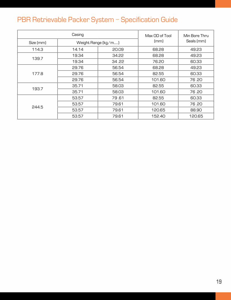
PBR Retrievable Packer System
Description
The Retrievable PBR System offers maximum flexibility for completing deep wells or wells where multiple zone testing is required. It may be required where an extra large seal bore size is required for production.
A permanent packer system is normally set in the casing, and the PBR is run in with the seal assembly in a single trip using a shear released locator seal assembly. The PBR is latched into the permanent packer to anchor and seal. Landing nipples and tailpipe can be stung through, or can be attached to the packer.
The PBR can be retrieved using a latch style retrieving tool. A variety of seal materials are available depending on well conditions. CRA materials are available upon request.
The Perma-Plus series is available in 10K and 15K pressure rating.
Features
• Continuous bore
• Single trip running with the seal assembly
• Rotational release and running tool
• PBR retrievable
Casing Max OD of Tool (in)
Min Bore Thru Seals (in)Size (in) Weight Range (lb/ft.)
4-1/2” 9.5 13.5 2.688 1.94
5-1/2”13 23 2.688 1.94
13 23 3.000 2.38
7
20 38 2.688 1.94
20 38 3.250 2.38
20 38 4.000 3.00
7 5/824 39 3.250 2.38
24 39 4.000 3.00
9 5/8
36 53.5 3.250 2.38
36 53.5 4.000 3.00
36 53.5 4.750 3.50
36 53.5 6.000 4.75
Specification Guide
19
PBR Retrievable Packer System - Specification Guide
Casing Max OD of Tool (mm)
Min Bore Thru Seals (mm)Size (mm) Weight Range (kg/m.....)
114.3 14.14 20.09 68.28 49.23
139.719.34 34.22 68.28 49.23
19.34 34 .22 76.20 60.33
177.8
29.76 56.54 68.28 49.23
29.76 56.54 82.55 60.33
29.76 56.54 101.60 76 .20
193.735.71 58.03 82.55 60.33
35.71 58.03 101.60 76 .20
244.5
53.57 79 .61 82.55 60.33
53.57 79.61 101.60 76 .20
53.57 79.61 120.65 88.90
53.57 79.61 152.40 120.65
20
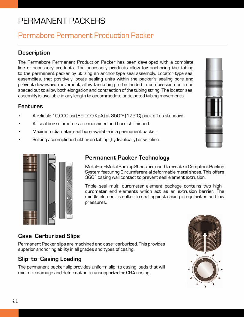
Permabore Permanent Production Packer
Description
The Permabore Permanent Production Packer has been developed with a complete line of accessory products. The accessory products allow for anchoring the tubing to the permanent packer by utilizing an anchor type seal assembly. Locator type seal assemblies, that positively locate sealing units within the packer’s sealing bore and prevent downward movement, allow the tubing to be landed in compression or to be spaced out to allow both elongation and contraction of the tubing string. The locator seal assembly is available in any length to accommodate anticipated tubing movements.
Features
• A reliable 10,000 psi (69,000 KpA) at 350°F (175°C) pack off as standard.
• All seal bore diameters are machined and burnish finished.
• Maximum diameter seal bore available in a permanent packer.
• Setting accomplished either on tubing (hydraulically) or wireline.
Permanent Packer Technology
Metal-to-Metal Backup Shoes are used to create a Compliant Backup System featuring Circumferential deformable metal shoes. This offers 360° casing wall contact to prevent seal element extrusion.
Triple-seal multi-durometer element package contains two high-durometer end elements which act as an extrusion barrier. The middle element is softer to seal against casing irregularities and low pressures.
Case-Carburized SlipsPermanent Packer slips are machined and case-carburized. This provides superior anchoring ability in all grades and types of casing.
Slip-to-Casing LoadingThe permanent packer slip provides uniform slip-to casing loads that will minimize damage and deformation to unsupported or CRA casing.
PERMANENT PACKERS
21
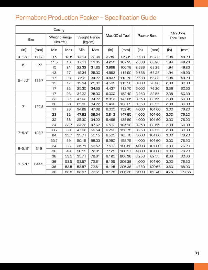
Permabore Production Packer - Specification Guide
Casing
Max OD of Tool Packer BoreMin Bore
Thru SealsSizeWeight Range
(lbs/ft.)Weight Range
(kg/m)
(in) (mm) Min Max Min Max (in) (mm) (in) (mm) (in) (mm)
4-1/2” 114.3 9.5 13.5 14.14 20.09 3.750 95.25 2.688 68.28 1.94 49.23
5” 12711.5 13 17.11 19.35 4.250 107.95 2.688 68.28 1.94 49.23
15 21 22.32 31.25 3.968 100.78 2.688 68.28 1.94 49.23
5-1/2” 139.7
13 17 19.34 25.30 4.563 115.90 2.688 68.28 1.94 49.23
17 23 25.3 34.22 4.437 112.70 2.688 68.28 1.94 49.23
13 17 19.34 25.30 4.563 115.90 3.000 76.20 2.38 60.33
17 23 25.30 34.22 4.437 112.70 3.000 76.20 2.38 60.33
7” 177.8
17 23 34.22 25.30 6.000 152.40 3.250 82.55 2.38 60.33
23 32 47.62 34.22 5.813 147.65 3.250 82.55 2.38 60.33
32 38 25.30 34.22 5.468 138.89 3.250 82.55 2.38 60.33
17 23 34.22 47.62 6.000 152.40 4.000 101.60 3.00 76.20
23 32 47.62 56.54 5.813 147.65 4.000 101.60 3.00 76.20
32 38 25.30 34.22 5.468 138.89 4.000 101.60 3.00 76.20
7-5/8” 193.7
24 33.7 34.22 47.62 6.500 165.10 3.250 82.55 2.38 60.33
33.7 39 47.62 56.54 6.250 158.75 3.250 82.55 2.38 60.33
24 33.7 35.71 50.15 6.500 165.10 4.000 101.60 3.00 76.20
33.7 39 50.15 58.03 6.250 158.75 4.000 101.60 3.00 76.20
8-5/8” 21924 36 35.71 53.57 7.500 190.50 4.000 101.60 3.00 76.20
36 49 50.15 72.91 7.125 180.97 4.000 101.60 3.00 76.20
9-5/8” 244.5
36 53.5 35.71 72.61 8.125 206.38 3.250 82.55 2.38 60.33
36 53.5 53.57 72.61 8.125 206.38 4.000 101.60 3.00 76.20
36 53.5 53.57 72.61 8.125 206.38 4.750 120.65 3.50 88.90
36 53.5 53.57 72.61 8.125 206.38 6.000 152.40 4.75 120.65
22
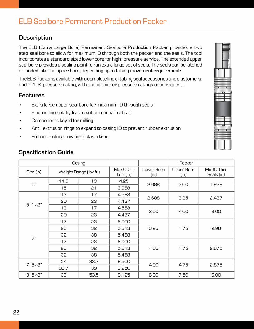
ELB Sealbore Permanent Production Packer
Description
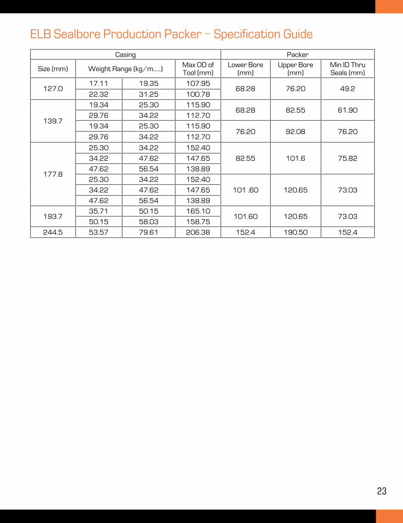
The ELB (Extra Large Bore) Permanent Sealbore Production Packer provides a two step seal bore to allow for maximum ID through both the packer and the seals. The tool incorporates a standard sized lower bore for high-pressure service. The extended upper seal bore provides a sealing point for an extra large set of seals. The seals can be latched or landed into the upper bore, depending upon tubing movement requirements.
The ELB Packer is available with a complete line of tubing seal accessories and elastomers, and in 10K pressure rating, with special higher pressure ratings upon request.
Features
• Extra large upper seal bore for maximum ID through seals
• Electric line set, hydraulic set or mechanical set
• Components keyed for milling
• Anti-extrusion rings to expand to casing ID to prevent rubber extrusion
• Full circle slips allow for fast run time
Specification Guide
Casing Packer
Size (in) Weight Range (lb/ft.)Max OD of
Tool (in)Lower Bore
(in)Upper Bore
(in)Min ID Thru
Seals (in)
5”11.5 13 4.25
2.688 3.00 1.93815 21 3.968
5-1/2”
13 17 4.5632.688 3.25 2.437
20 23 4.437
13 17 4.5633.00 4.00 3.00
20 23 4.437
7”
17 23 6.000
3.25 4.75 2.9823 32 5.813
32 38 5.468
17 23 6.000
4.00 4.75 2.87523 32 5.813
32 38 5.468
7-5/8”24 33.7 6.500
4.00 4.75 2.87533.7 39 6.250
9-5/8” 36 53.5 8.125 6.00 7.50 6.00
23
Casing Packer
Size (mm) Weight Range (kg/m.....)Max OD of Tool (mm)
Lower Bore (mm)
Upper Bore (mm)
Min ID Thru Seals (mm)
127.017.11 19.35 107.95
68.28 76.20 49.222.32 31.25 100.78
139.7
19.34 25.30 115.9068.28 82.55 61.90
29.76 34.22 112.70
19.34 25.30 115.9076.20 92.08 76.20
29.76 34.22 112.70
177.8
25.30 34.22 152.40
82.55 101.6 75.8234.22 47.62 147.65
47.62 56.54 138.89
25.30 34.22 152.40
101 .60 120.65 73.0334.22 47.62 147.65
47.62 56.54 138.89
193.735.71 50.15 165.10
101.60 120.65 73.0350.15 58.03 158.75
244.5 53.57 79.61 206.38 152.4 190.50 152.4
ELB Sealbore Production Packer - Specification Guide
24
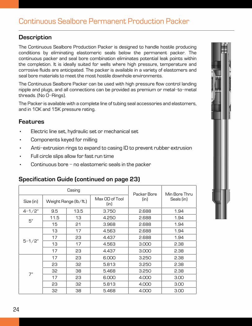
Continuous Sealbore Permanent Production Packer
Description
The Continuous Sealbore Production Packer is designed to handle hostile producing conditions by eliminating elastomeric seals below the permanent packer. The continuous packer and seal bore combination eliminates potential leak points within the completion. It is ideally suited for wells where high pressure, temperature and corrosive fluids are anticipated. The packer is available in a variety of elastomers and seal bore materials to meet the most hostile downhole environments.
The Continuous Sealbore Packer can be used with high pressure flow control landing nipple and plugs, and all connections can be provided as premium or metal-to-metal threads. (No O-Rings).
The Packer is available with a complete line of tubing seal accessories and elastomers, and in 10K and 15K pressure rating.
Features
• Electric line set, hydraulic set or mechanical set
• Components keyed for milling
• Anti-extrusion rings to expand to casing ID to prevent rubber extrusion
• Full circle slips allow for fast run time
• Continuous bore - no elastomeric seals in the packer
Specification Guide (continued on page 23)
CasingPacker Bore
(in)Min Bore Thru
Seals (in)Size (in) Weight Range (lb/ft.)Max OD of Tool
(in)
4-1/2” 9.5 13.5 3.750 2.688 1.94
5”11.5 13 4.250 2.688 1.94
15 21 3.968 2.688 1.94
5-1/2”
13 17 4.563 2.688 1.94
17 23 4.437 2.688 1.94
13 17 4.563 3.000 2.38
17 23 4.437 3.000 2.38
7”
17 23 6.000 3.250 2.38
23 32 5.813 3.250 2.38
32 38 5.468 3.250 2.38
17 23 6.000 4.000 3.00
23 32 5.813 4.000 3.00
32 38 5.468 4.000 3.00
25
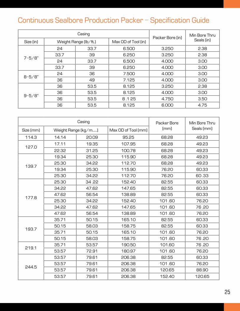
CasingPacker Bore (in)
Min Bore Thru Seals (in)Size (in) Weight Range (lb/ft.) Max OD of Tool (in)
7-5/8”
24 33.7 6.500 3.250 2.38
33.7 39 6.250 3.250 2.38
24 33.7 6.500 4.000 3.00
33.7 39 6.250 4.000 3.00
8-5/8”24 36 7.500 4.000 3.00
36 49 7.125 4.000 3.00
9-5/8”
36 53.5 8.125 3.250 2.38
36 53.5 8.125 4.000 3.00
36 53.5 8 .1 25 4.750 3.50
36 53.5 8.125 6.000 4.75
Continuous Sealbore Production Packer - Specification Guide
Casing Packer Bore (mm)
Min Bore Thru Seals (mm)Size (mm) Weight Range (kg/m.....) Max OD of Tool (mm)
114.3 14.14 20.09 95.25 68.28 49.23
127.017.11 19.35 107.95 68.28 49.23
22.32 31.25 100.78 68.28 49.23
139.7
19.34 25.30 115.90 68.28 49.23
25.30 34.22 112.70 68.28 49.23
19.34 25.30 115.90 76.20 60.33
25.30 34.22 112.70 76.20 60 .33
177.8
25.30 34 .22 152.40 82.55 60.33
34.22 47.62 147.65 82.55 60.33
47.62 56.54 138.89 82.55 60.33
25.30 34.22 152.40 101 .60 76.20
34.22 47.62 147.65 101 .60 76 .20
47.62 56.54 138.89 101 .60 76.20
193.7
35.71 50.15 165.10 82.55 60.33
50.15 58.03 158.75 82.55 60.33
35.71 50.15 165.10 101 .60 76.20
50.15 58.03 158.75 101 .60 76 .20
219.135.71 53.57 190.50 101.60 76 .20
53.57 72.91 180.97 101 .60 76.20
244.5
53.57 79.61 206.38 82.55 60.33
53.57 79.61 206.38 101 .60 76.20
53.57 79.61 206.38 120.65 88.90
53.57 79.61 206.38 152.40 120.65
26
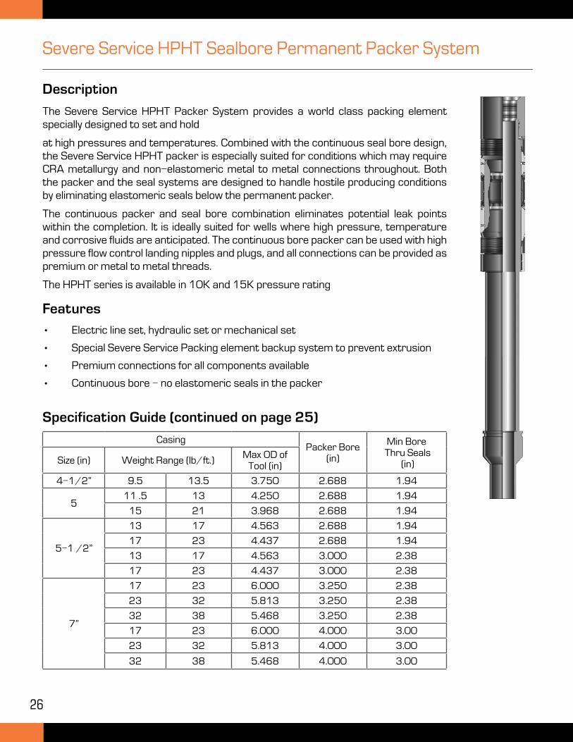
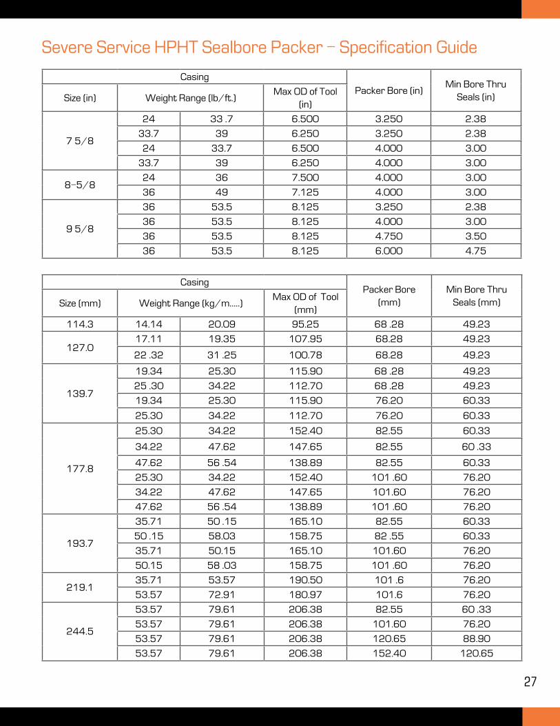
Severe Service HPHT Sealbore Permanent Packer System
CasingPacker Bore
(in)
Min Bore Thru Seals
(in)Size (in) Weight Range (lb/ft.)Max OD of
Tool (in)
4-1/2” 9.5 13.5 3.750 2.688 1.94
511 .5 13 4.250 2.688 1.94
15 21 3.968 2.688 1.94
5-1 /2”
13 17 4.563 2.688 1.94
17 23 4.437 2.688 1.94
13 17 4.563 3.000 2.38
17 23 4.437 3.000 2.38
7”
17 23 6.000 3.250 2.38
23 32 5.813 3.250 2.38
32 38 5.468 3.250 2.38
17 23 6.000 4.000 3.00
23 32 5.813 4.000 3.00
32 38 5.468 4.000 3.00
Specification Guide (continued on page 25)
Features
• Electric line set, hydraulic set or mechanical set
• Special Severe Service Packing element backup system to prevent extrusion
• Premium connections for all components available
• Continuous bore - no elastomeric seals in the packer
Description
The Severe Service HPHT Packer System provides a world class packing element specially designed to set and hold
at high pressures and temperatures. Combined with the continuous seal bore design, the Severe Service HPHT packer is especially suited for conditions which may require CRA metallurgy and non-elastomeric metal to metal connections throughout. Both the packer and the seal systems are designed to handle hostile producing conditions by eliminating elastomeric seals below the permanent packer.
The continuous packer and seal bore combination eliminates potential leak points within the completion. It is ideally suited for wells where high pressure, temperature and corrosive fluids are anticipated. The continuous bore packer can be used with high pressure flow control landing nipples and plugs, and all connections can be provided as premium or metal to metal threads.
The HPHT series is available in 10K and 15K pressure rating
27
Casing
Packer Bore (in)Min Bore Thru
Seals (in)Size (in) Weight Range (lb/ft.)Max OD of Tool
(in)
7 5/8
24 33 .7 6.500 3.250 2.38
33.7 39 6.250 3.250 2.38
24 33.7 6.500 4.000 3.00
33.7 39 6.250 4.000 3.00
8-5/824 36 7.500 4.000 3.00
36 49 7.125 4.000 3.00
9 5/8
36 53.5 8.125 3.250 2.38
36 53.5 8.125 4.000 3.00
36 53.5 8.125 4.750 3.50
36 53.5 8.125 6.000 4.75
Severe Service HPHT Sealbore Packer - Specification Guide
CasingPacker Bore
(mm)Min Bore Thru
Seals (mm)Size (mm) Weight Range (kg/m.....)Max OD of Tool
(mm)
114.3 14.14 20.09 95.25 68 .28 49.23
127.017.11 19.35 107.95 68.28 49.23
22 .32 31 .25 100.78 68.28 49.23
139.7
19.34 25.30 115.90 68 .28 49.23
25 .30 34.22 112.70 68 .28 49.23
19.34 25.30 115.90 76.20 60.33
25.30 34.22 112.70 76.20 60.33
177.8
25.30 34.22 152.40 82.55 60.33
34.22 47.62 147.65 82.55 60 .33
47.62 56 .54 138.89 82.55 60.33
25.30 34.22 152.40 101 .60 76.20
34.22 47.62 147.65 101.60 76.20
47.62 56 .54 138.89 101 .60 76.20
193.7
35.71 50 .15 165.10 82.55 60.33
50 .15 58.03 158.75 82 .55 60.33
35.71 50.15 165.10 101.60 76.20
50.15 58 .03 158.75 101 .60 76.20
219.135.71 53.57 190.50 101 .6 76.20
53.57 72.91 180.97 101.6 76.20
244.5
53.57 79.61 206.38 82.55 60 .33
53.57 79.61 206.38 101.60 76.20
53.57 79.61 206.38 120.65 88.90
53.57 79.61 206.38 152.40 120.65
28
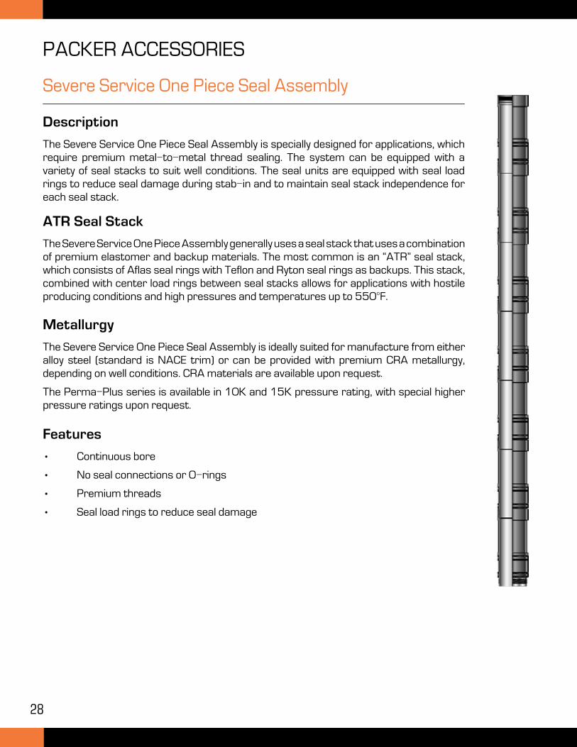
Severe Service One Piece Seal Assembly
Description
The Severe Service One Piece Seal Assembly is specially designed for applications, which require premium metal-to-metal thread sealing. The system can be equipped with a variety of seal stacks to suit well conditions. The seal units are equipped with seal load rings to reduce seal damage during stab-in and to maintain seal stack independence for each seal stack.
Features
• Continuous bore
• No seal connections or O-rings
• Premium threads
• Seal load rings to reduce seal damage
ATR Seal Stack
The Severe Service One Piece Assembly generally uses a seal stack that uses a combination of premium elastomer and backup materials. The most common is an “ATR” seal stack, which consists of Aflas seal rings with Teflon and Ryton seal rings as backups. This stack, combined with center load rings between seal stacks allows for applications with hostile producing conditions and high pressures and temperatures up to 550°F.
Metallurgy
The Severe Service One Piece Seal Assembly is ideally suited for manufacture from either alloy steel (standard is NACE trim) or can be provided with premium CRA metallurgy, depending on well conditions. CRA materials are available upon request.
The Perma-Plus series is available in 10K and 15K pressure rating, with special higher pressure ratings upon request.
PACKER ACCESSORIES
29
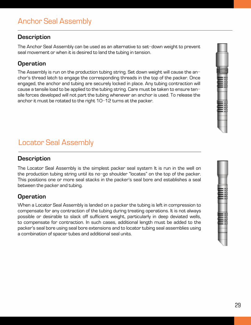
Description
The Anchor Seal Assembly can be used as an alternative to set-down weight to prevent seal movement or when it is desired to land the tubing in tension.
OperationThe Assembly is run on the production tubing string. Set down weight will cause the an-chor’s thread latch to engage the corresponding threads in the top of the packer. Once engaged, the anchor and tubing are securely locked in place. Any tubing contraction will cause a tensile load to be applied to the tubing string. Care must be taken to ensure ten-sile forces developed will not part the tubing whenever an anchor is used. To release the anchor it must be rotated to the right 10-12 turns at the packer.
Anchor Seal Assembly
Description
The Locator Seal Assembly is the simplest packer seal system It is run in the well on the production tubing string until its no-go shoulder “locates” on the top of the packer. This positions one or more seal stacks in the packer’s seal bore and establishes a seal between the packer and tubing.
OperationWhen a Locator Seal Assembly is landed on a packer the tubing is left in compression to compensate for any contraction of the tubing during treating operations. It is not always possible or desirable to slack off sufficient weight, particularly in deep deviated wells, to compensate for contraction. In such cases, additional length must be added to the packer’s seal bore using seal bore extensions and to locator tubing seal assemblies using a combination of spacer tubes and additional seal units.
Locator Seal Assembly
30
RETRIEVABLE BRIDGE PLUGS
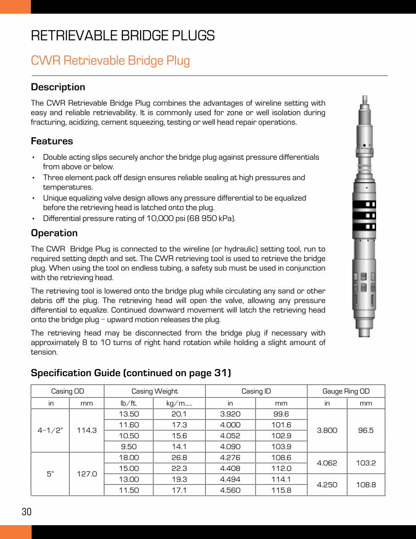
CWR Retrievable Bridge Plug
Description
The CWR Retrievable Bridge Plug combines the advantages of wireline setting with easy and reliable retrievability. It is commonly used for zone or well isolation during fracturing, acidizing, cement squeezing, testing or well head repair operations.
Operation
The CWR Bridge Plug is connected to the wireline (or hydraulic) setting tool, run to required setting depth and set. The CWR retrieving tool is used to retrieve the bridge plug. When using the tool on endless tubing, a safety sub must be used in conjunction with the retrieving head.
The retrieving tool is lowered onto the bridge plug while circulating any sand or other debris off the plug. The retrieving head will open the valve, allowing any pressure differential to equalize. Continued downward movement will latch the retrieving head onto the bridge plug - upward motion releases the plug.
The retrieving head may be disconnected from the bridge plug if necessary with approximately 8 to 10 turns of right hand rotation while holding a slight amount of tension.
Casing OD Casing Weight Casing ID Gauge Ring OD
in mm lb/ft. kg/m..... in mm in mm
4-1/2” 114.3
13.50 20.1 3.920 99.6
3.800 96.511.60 17.3 4.000 101.6
10.50 15.6 4.052 102.9
9.50 14.1 4.090 103.9
5” 127.0
18.00 26.8 4.276 108.64.062 103.2
15.00 22.3 4.408 112.0
13.00 19.3 4.494 114.14.250 108.8
11.50 17.1 4.560 115.8
Specification Guide (continued on page 31)
Features
• Double acting slips securely anchor the bridge plug against pressure differentials from above or below.
• Three element pack off design ensures reliable sealing at high pressures and temperatures.
• Unique equalizing valve design allows any pressure differential to be equalized before the retrieving head is latched onto the plug.
• Differential pressure rating of 10,000 psi (68 950 kPa).
31
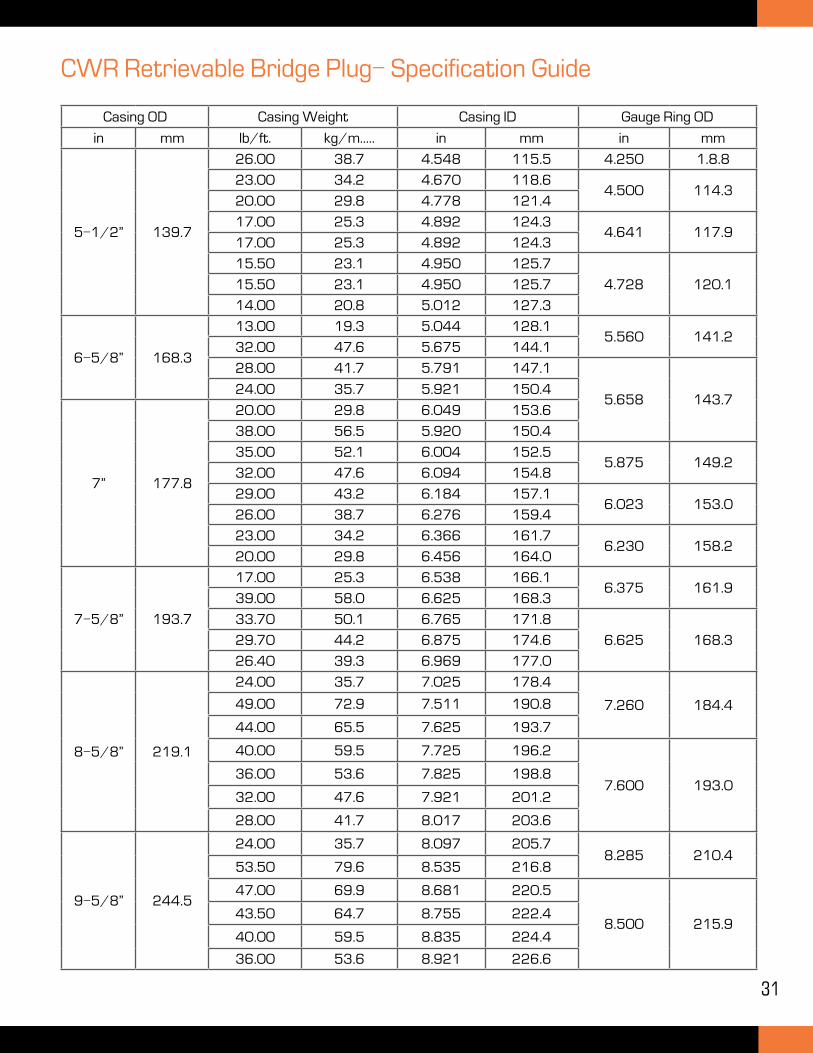
CWR Retrievable Bridge Plug- Specification Guide
Casing OD Casing Weight Casing ID Gauge Ring OD
in mm lb/ft. kg/m..... in mm in mm
5-1/2” 139.7
26.00 38.7 4.548 115.5 4.250 1.8.8
23.00 34.2 4.670 118.64.500 114.3
20.00 29.8 4.778 121.4
17.00 25.3 4.892 124.34.641 117.9
17.00 25.3 4.892 124.3
15.50 23.1 4.950 125.7
4.728 120.115.50 23.1 4.950 125.7
14.00 20.8 5.012 127.3
6-5/8” 168.3
13.00 19.3 5.044 128.15.560 141.2
32.00 47.6 5.675 144.1
28.00 41.7 5.791 147.1
5.658 143.724.00 35.7 5.921 150.4
7” 177.8
20.00 29.8 6.049 153.6
38.00 56.5 5.920 150.4
35.00 52.1 6.004 152.55.875 149.2
32.00 47.6 6.094 154.8
29.00 43.2 6.184 157.16.023 153.0
26.00 38.7 6.276 159.4
23.00 34.2 6.366 161.76.230 158.2
20.00 29.8 6.456 164.0
7-5/8” 193.7
17.00 25.3 6.538 166.16.375 161.9
39.00 58.0 6.625 168.3
33.70 50.1 6.765 171.8
6.625 168.329.70 44.2 6.875 174.6
26.40 39.3 6.969 177.0
8-5/8” 219.1
24.00 35.7 7.025 178.4
7.260 184.449.00 72.9 7.511 190.8
44.00 65.5 7.625 193.7
40.00 59.5 7.725 196.2
7.600 193.036.00 53.6 7.825 198.8
32.00 47.6 7.921 201.2
28.00 41.7 8.017 203.6
9-5/8” 244.5
24.00 35.7 8.097 205.78.285 210.4
53.50 79.6 8.535 216.8
47.00 69.9 8.681 220.5
8.500 215.943.50 64.7 8.755 222.4
40.00 59.5 8.835 224.4
36.00 53.6 8.921 226.6
32
C-TS 10K Retrievable Bridge Plug
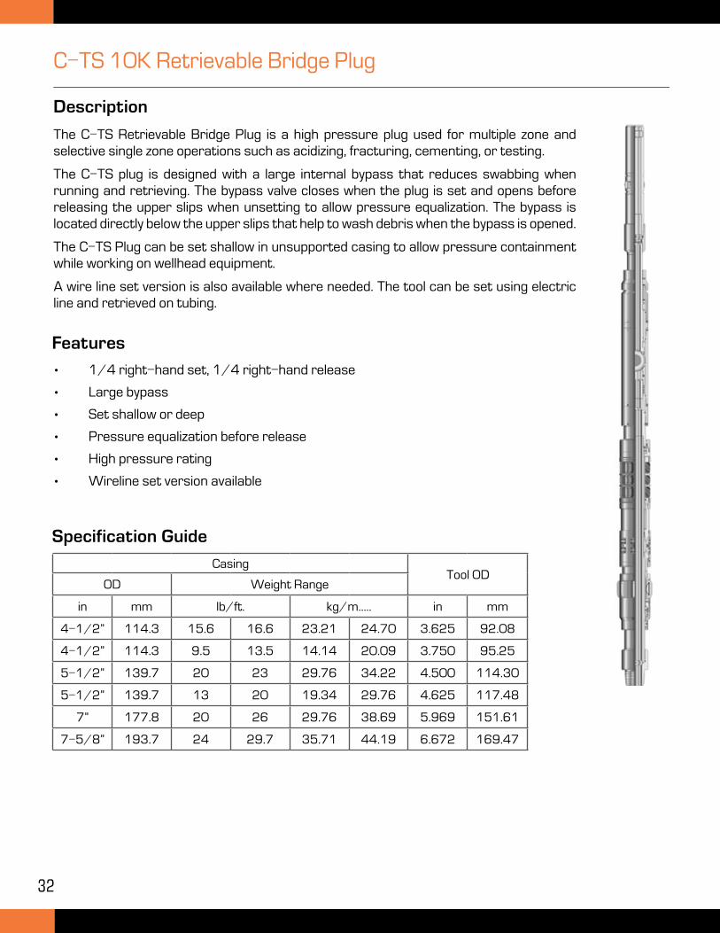
Description
The C-TS Retrievable Bridge Plug is a high pressure plug used for multiple zone and selective single zone operations such as acidizing, fracturing, cementing, or testing.
The C-TS plug is designed with a large internal bypass that reduces swabbing when running and retrieving. The bypass valve closes when the plug is set and opens before releasing the upper slips when unsetting to allow pressure equalization. The bypass is located directly below the upper slips that help to wash debris when the bypass is opened.
The C-TS Plug can be set shallow in unsupported casing to allow pressure containment while working on wellhead equipment.
A wire line set version is also available where needed. The tool can be set using electric line and retrieved on tubing.
Specification Guide
CasingTool OD
OD Weight Range
in mm lb/ft. kg/m..... in mm
4-1/2” 114.3 15.6 16.6 23.21 24.70 3.625 92.08
4-1/2” 114.3 9.5 13.5 14.14 20.09 3.750 95.25
5-1/2” 139.7 20 23 29.76 34.22 4.500 114.30
5-1/2” 139.7 13 20 19.34 29.76 4.625 117.48
7” 177.8 20 26 29.76 38.69 5.969 151.61
7-5/8” 193.7 24 29.7 35.71 44.19 6.672 169.47
Features
• 1/4 right-hand set, 1/4 right-hand release
• Large bypass
• Set shallow or deep
• Pressure equalization before release
• High pressure rating
• Wireline set version available
33
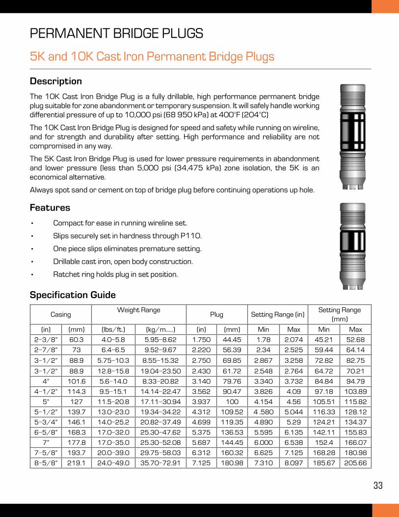
5K and 10K Cast Iron Permanent Bridge Plugs
Description
The 10K Cast Iron Bridge Plug is a fully drillable, high performance permanent bridge plug suitable for zone abandonment or temporary suspension. It will safely handle working differential pressure of up to 10,000 psi (68 950 kPa) at 400°F (204°C)
The 10K Cast Iron Bridge Plug is designed for speed and safety while running on wireline, and for strength and durability after setting. High performance and reliability are not compromised in any way.
The 5K Cast Iron Bridge Plug is used for lower pressure requirements in abandonment and lower pressure (less than 5,000 psi (34,475 kPa) zone isolation, the 5K is an economical alternative.
Always spot sand or cement on top of bridge plug before continuing operations up hole.
Features
• Compact for ease in running wireline set.
• Slips securely set in hardness through P110.
• One piece slips eliminates premature setting.
• Drillable cast iron, open body construction.
• Ratchet ring holds plug in set position.
PERMANENT BRIDGE PLUGS
CasingWeight Range
Plug Setting Range (in)Setting Range
(mm)
(in) (mm) (lbs/ft.) (kg/m.....) (in) (mm) Min Max Min Max
2-3/8” 60.3 4.0-5.8 5.95-8.62 1.750 44.45 1.78 2.074 45.21 52.68
2-7/8” 73 6.4-6.5 9.52-9.67 2.220 56.39 2.34 2.525 59.44 64.14
3-1/2” 88.9 5.75-10.3 8.55-15.32 2.750 69.85 2.867 3.258 72.82 82.75
3-1/2” 88.9 12.8-15.8 19.04-23.50 2.430 61.72 2.548 2.764 64.72 70.21
4” 101.6 5.6-14.0 8.33-20.82 3.140 79.76 3.340 3.732 84.84 94.79
4-1/2” 114.3 9.5-15.1 14.14-22.47 3.562 90.47 3.826 4.09 97.18 103.89
5” 127 11.5-20.8 17.11-30.94 3.937 100 4.154 4.56 105.51 115.82
5-1/2” 139.7 13.0-23.0 19.34-34.22 4.312 109.52 4 .580 5.044 116.33 128.12
5-3/4” 146.1 14.0-25.2 20.82-37.49 4.699 119.35 4.890 5.29 124.21 134.37
6-5/8” 168.3 17.0-32.0 25.30-47.62 5.375 136.53 5.595 6.135 142.11 155.83
7” 177.8 17.0-35.0 25.30-52.08 5.687 144.45 6.000 6.538 152.4 166.07
7-5/8” 193.7 20.0-39.0 29.75-58.03 6.312 160.32 6.625 7.125 168.28 180.98
8-5/8” 219.1 24.0-49.0 35.70-72.91 7.125 180.98 7.310 8.097 185.67 205.66
Specification Guide
34
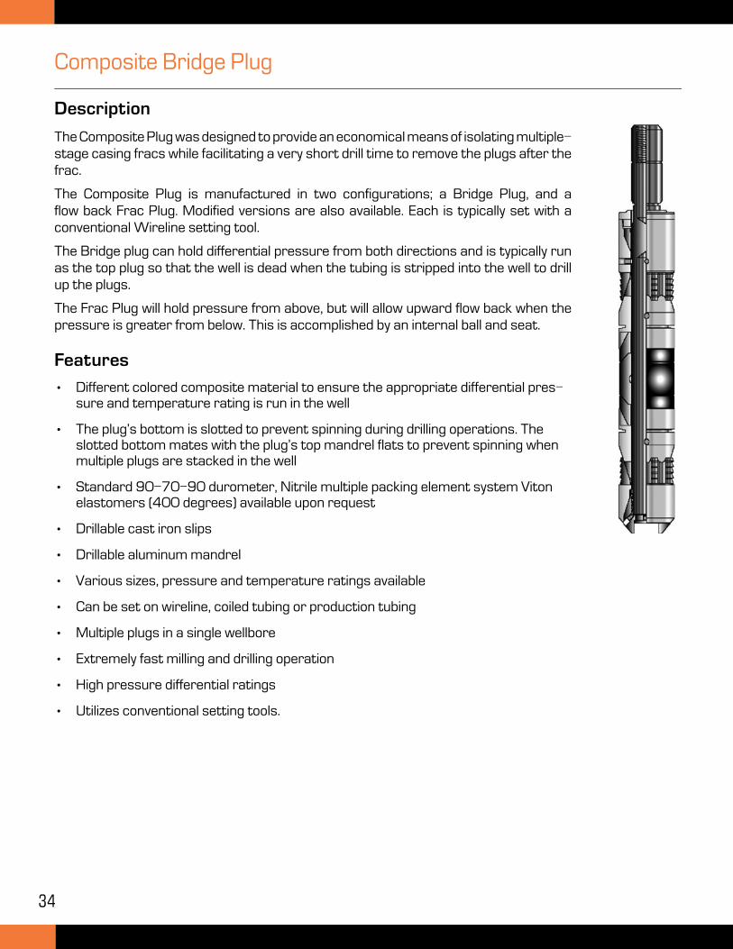
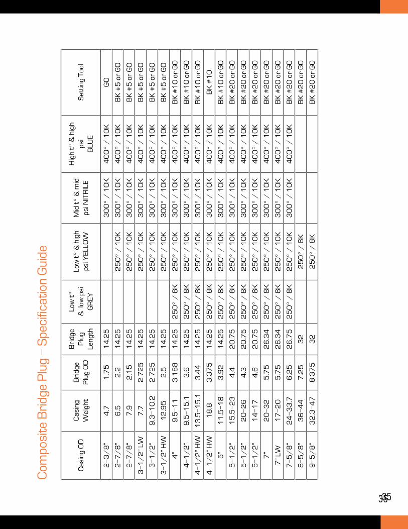
Composite Bridge Plug
Description
The Composite Plug was designed to provide an economical means of isolating multiple-stage casing fracs while facilitating a very short drill time to remove the plugs after the frac.
The Composite Plug is manufactured in two configurations; a Bridge Plug, and a flow back Frac Plug. Modified versions are also available. Each is typically set with a conventional Wireline setting tool.
The Bridge plug can hold differential pressure from both directions and is typically run as the top plug so that the well is dead when the tubing is stripped into the well to drill up the plugs.
The Frac Plug will hold pressure from above, but will allow upward flow back when the pressure is greater from below. This is accomplished by an internal ball and seat.
Features
• Different colored composite material to ensure the appropriate differential pres-sure and temperature rating is run in the well
• The plug’s bottom is slotted to prevent spinning during drilling operations. The slotted bottom mates with the plug’s top mandrel flats to prevent spinning when multiple plugs are stacked in the well
• Standard 90-70-90 durometer, Nitrile multiple packing element system Viton elastomers (400 degrees) available upon request
• Drillable cast iron slips
• Drillable aluminum mandrel
• Various sizes, pressure and temperature ratings available
• Can be set on wireline, coiled tubing or production tubing
• Multiple plugs in a single wellbore
• Extremely fast milling and drilling operation
• High pressure differential ratings
• Utilizes conventional setting tools.
35
Cas
ing
OD
Cas
ing
Wei
ght
Bri
dge
Plu
g O
D
Bri
dge
Plu
g Le
ngth
Low
t°
& l
ow p
si
GR
EY
Low
t°
& h
igh
psi Y
ELL
OW
Mid
t°
& m
id
psi N
ITR
ILE
Hig
h t°
& h
igh
psi
BLU
ES
etti
ng T
ool
2-3
/8
”4
.71
.75
14
.25
30
0°
/ 1
0K
40
0°
/ 1
0K
GO
2-7
/8
”6
.52
.21
4.2
52
50
° /
10
K3
00
° /
10
K4
00
° /
10
KB
K #
5 o
r G
O
2-7
/8
”7
.92
.15
14
.25
25
0°
/ 1
0K
30
0°
/ 1
0K
40
0°
/ 1
0K
BK
#5
or
GO
3-1
/2
” LW
7.7
2.7
25
14
.25
25
0°
/ 1
0K
30
0°
/ 1
0K
40
0°
/ 1
0K
BK
#5
or
GO
3-1
/2
”9
.3-1
0.2
2.7
25
14
.25
25
0°
/ 1
0K
30
0°
/ 1
0K
40
0°
/ 1
0K
BK
#5
or
GO
3-1
/2
” HW
12
.95
2.5
14
.25
25
0°
/ 1
0K
30
0°
/ 1
0K
40
0°
/ 1
0K
BK
#5
or
GO
4”
9.5
-11
3.1
88
14
.25
25
0°
/ 8
K2
50
° /
10
K3
00
° /
10
K4
00
° /
10
KB
K #
10
or
GO
4-1
/2
”9
.5-1
5.1
3.6
14
.25
25
0°
/ 8
K2
50
° /
10
K3
00
° /
10
K4
00
° /
10
KB
K #
10
or
GO
4-1
/2
” HW
13
.5-1
5.1
3.4
41
4.2
52
50
° /
8K
25
0°
/ 1
0K
30
0°
/ 1
0K
40
0°
/ 1
0K
BK
#1
0 o
r G
O
4-1
/2
” HW
18
.83
.37
51
4.2
52
50
° /
8K
25
0°
/ 1
0K
30
0°
/ 1
0K
40
0°
/ 1
0K
BK
#1
0
5”
11
.5-1
83
.92
14
.25
25
0°
/ 8
K2
50
° /
10
K3
00
° /
10
K4
00
° /
10
KB
K #
10
or
GO
5-1
/2
”1
5.5
-23
4.4
20
.75
25
0°
/ 8
K2
50
° /
10
K3
00
° /
10
K4
00
° /
10
KB
K #
20
or
GO
5-1
/2
”2
0-2
64
.32
0.7
52
50
° /
8K
25
0°
/ 1
0K
30
0°
/ 1
0K
40
0°
/ 1
0K
BK
#2
0 o
r G
O
5-1
/2
”1
4-1
74
.62
0.7
52
50
° /
8K
25
0°
/ 1
0K
30
0°
/ 1
0K
40
0°
/ 1
0K
BK
#2
0 o
r G
O
7”
20
-32
5.7
52
6.3
42
50
° /
8K
25
0°
/ 1
0K
30
0°
/ 1
0K
40
0°
/ 1
0K
BK
#2
0 o
r G
O
7” L
W1
7-2
05
.75
26
.34
25
0°
/ 8
K2
50
° /
10
K3
00
° /
10
K4
00
° /
10
KB
K #
20
or
GO
7-5
/8
”2
4-3
3.7
6.2
52
6.7
52
50
° /
8K
25
0°
/ 1
0K
30
0°
/ 1
0K
40
0°
/ 1
0K
BK
#2
0 o
r G
O
8-5
/8
”3
6-4
47
.25
32
25
0°
/ 8
KB
K #
20
or
GO
9-5
/8
”3
2.3
-47
8.3
75
32
25
0°
/ 8
KB
K #
20
or
GO
Com
posi
te B
ridg
e P
lug
- S
peci
ficat
ion
Gui
de
35
36
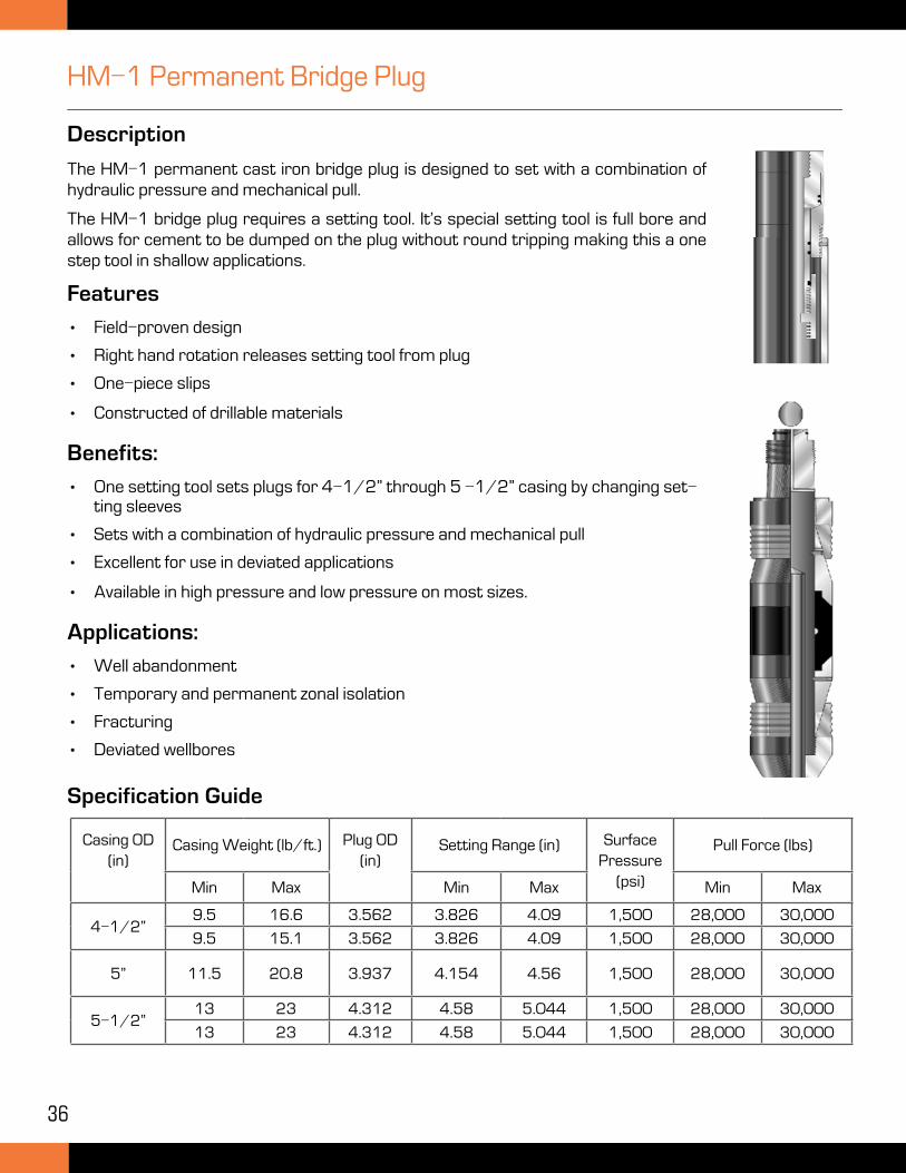
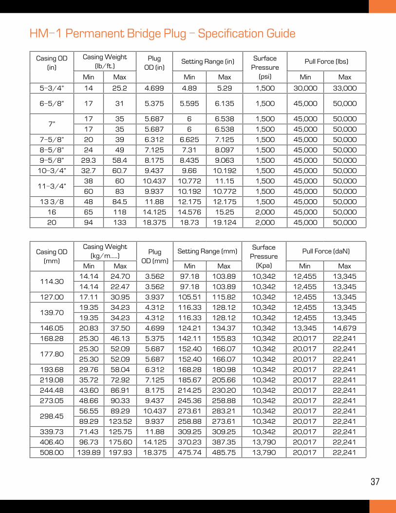
HM-1 Permanent Bridge Plug
Description
The HM-1 permanent cast iron bridge plug is designed to set with a combination of hydraulic pressure and mechanical pull.
The HM-1 bridge plug requires a setting tool. It’s special setting tool is full bore and allows for cement to be dumped on the plug without round tripping making this a one step tool in shallow applications.
Specification Guide
Casing OD (in)
Casing Weight (lb/ft.) Plug OD (in)
Setting Range (in) Surface Pressure
(psi)
Pull Force (lbs)
Min Max Min Max Min Max
4-1/2”9.5 16.6 3.562 3.826 4.09 1,500 28,000 30,000
9.5 15.1 3.562 3.826 4.09 1,500 28,000 30,000
5” 11.5 20.8 3.937 4.154 4.56 1,500 28,000 30,000
5-1/2”13 23 4.312 4.58 5.044 1,500 28,000 30,000
13 23 4.312 4.58 5.044 1,500 28,000 30,000
Features
• Field-proven design
• Right hand rotation releases setting tool from plug
• One-piece slips
• Constructed of drillable materials
Benefits:
• One setting tool sets plugs for 4-1/2” through 5 -1/2” casing by changing set-ting sleeves
• Sets with a combination of hydraulic pressure and mechanical pull
• Excellent for use in deviated applications
• Available in high pressure and low pressure on most sizes.
Applications:
• Well abandonment
• Temporary and permanent zonal isolation
• Fracturing
• Deviated wellbores
37
Casing OD (in)
Casing Weight (lb/ft.)
Plug OD (in)
Setting Range (in) Surface Pressure
(psi)
Pull Force (lbs)
Min Max Min Max Min Max
5-3/4” 14 25.2 4.699 4.89 5.29 1,500 30,000 33,000
6-5/8” 17 31 5.375 5.595 6.135 1,500 45,000 50,000
7”17 35 5.687 6 6.538 1,500 45,000 50,000
17 35 5.687 6 6.538 1,500 45,000 50,000
7-5/8” 20 39 6.312 6.625 7.125 1,500 45,000 50,000
8-5/8” 24 49 7.125 7.31 8.097 1,500 45,000 50,000
9-5/8” 29.3 58.4 8.175 8.435 9.063 1,500 45,000 50,000
10-3/4” 32.7 60.7 9.437 9.66 10.192 1,500 45,000 50,000
11-3/4”38 60 10.437 10.772 11.15 1,500 45,000 50,000
60 83 9.937 10.192 10.772 1,500 45,000 50,000
13 3/8 48 84.5 11.88 12.175 12.175 1,500 45,000 50,000
16 65 118 14.125 14.576 15.25 2,000 45,000 50,000
20 94 133 18.375 18.73 19.124 2,000 45,000 50,000
HM-1 Permanent Bridge Plug - Specification Guide
Casing OD (mm)
Casing Weight (kg/m.....)
Plug OD (mm)
Setting Range (mm)Surface
Pressure (Kpa)
Pull Force (daN)
Min Max Min Max Min Max
114.3014.14 24.70 3.562 97.18 103.89 10,342 12,455 13,345
14.14 22.47 3.562 97.18 103.89 10,342 12,455 13,345
127.00 17.11 30.95 3.937 105.51 115.82 10,342 12,455 13,345
139.7019.35 34.23 4.312 116.33 128.12 10,342 12,455 13,345
19.35 34.23 4.312 116.33 128.12 10,342 12,455 13,345
146.05 20.83 37.50 4.699 124.21 134.37 10,342 13,345 14,679
168.28 25.30 46.13 5.375 142.11 155.83 10,342 20,017 22,241
177.8025.30 52.09 5.687 152.40 166.07 10,342 20,017 22,241
25.30 52.09 5.687 152.40 166.07 10,342 20,017 22,241
193.68 29.76 58.04 6.312 168.28 180.98 10,342 20,017 22,241
219.08 35.72 72.92 7.125 185.67 205.66 10,342 20,017 22,241
244.48 43.60 86.91 8.175 214.25 230.20 10,342 20,017 22,241
273.05 48.66 90.33 9.437 245.36 258.88 10,342 20,017 22,241
298.4556.55 89.29 10.437 273.61 283.21 10,342 20,017 22,241
89.29 123.52 9.937 258.88 273.61 10,342 20,017 22,241
339.73 71.43 125.75 11.88 309.25 309.25 10,342 20,017 22,241
406.40 96.73 175.60 14.125 370.23 387.35 13,790 20,017 22,241
508.00 139.89 197.93 18.375 475.74 485.75 13,790 20,017 22,241
38
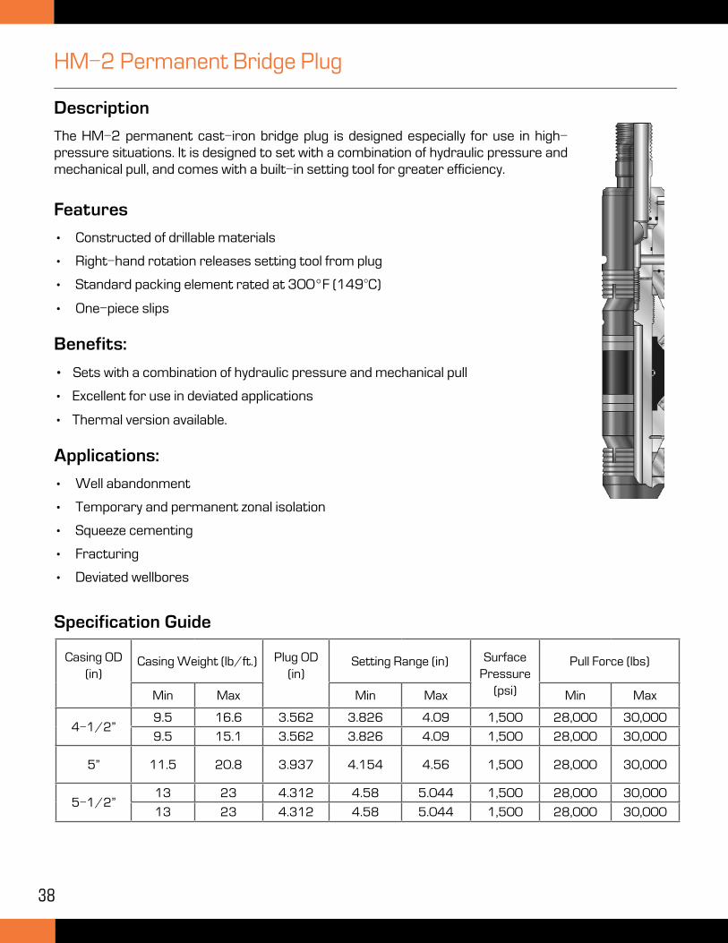
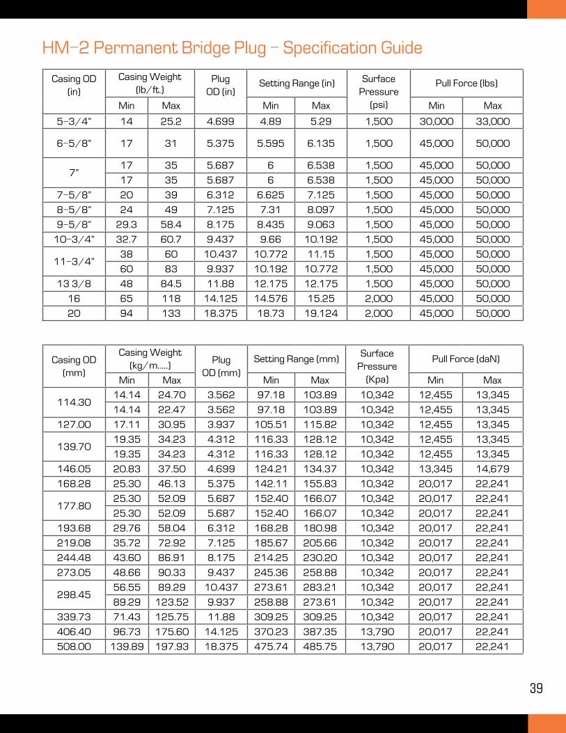
HM-2 Permanent Bridge Plug
Description
The HM-2 permanent cast-iron bridge plug is designed especially for use in high-pressure situations. It is designed to set with a combination of hydraulic pressure and mechanical pull, and comes with a built-in setting tool for greater efficiency.
Specification Guide
Casing OD (in)
Casing Weight (lb/ft.) Plug OD (in)
Setting Range (in) Surface Pressure
(psi)
Pull Force (lbs)
Min Max Min Max Min Max
4-1/2”9.5 16.6 3.562 3.826 4.09 1,500 28,000 30,000
9.5 15.1 3.562 3.826 4.09 1,500 28,000 30,000
5” 11.5 20.8 3.937 4.154 4.56 1,500 28,000 30,000
5-1/2”13 23 4.312 4.58 5.044 1,500 28,000 30,000
13 23 4.312 4.58 5.044 1,500 28,000 30,000
Features
• Constructed of drillable materials
• Right-hand rotation releases setting tool from plug
• Standard packing element rated at 300°F (149°C)
• One-piece slips
Benefits:
• Sets with a combination of hydraulic pressure and mechanical pull
• Excellent for use in deviated applications
• Thermal version available.
Applications:
• Well abandonment
• Temporary and permanent zonal isolation
• Squeeze cementing
• Fracturing
• Deviated wellbores
39
Casing OD (in)
Casing Weight (lb/ft.)
Plug OD (in)
Setting Range (in) Surface Pressure
(psi)
Pull Force (lbs)
Min Max Min Max Min Max
5-3/4” 14 25.2 4.699 4.89 5.29 1,500 30,000 33,000
6-5/8” 17 31 5.375 5.595 6.135 1,500 45,000 50,000
7”17 35 5.687 6 6.538 1,500 45,000 50,000
17 35 5.687 6 6.538 1,500 45,000 50,000
7-5/8” 20 39 6.312 6.625 7.125 1,500 45,000 50,000
8-5/8” 24 49 7.125 7.31 8.097 1,500 45,000 50,000
9-5/8” 29.3 58.4 8.175 8.435 9.063 1,500 45,000 50,000
10-3/4” 32.7 60.7 9.437 9.66 10.192 1,500 45,000 50,000
11-3/4”38 60 10.437 10.772 11.15 1,500 45,000 50,000
60 83 9.937 10.192 10.772 1,500 45,000 50,000
13 3/8 48 84.5 11.88 12.175 12.175 1,500 45,000 50,000
16 65 118 14.125 14.576 15.25 2,000 45,000 50,000
20 94 133 18.375 18.73 19.124 2,000 45,000 50,000
HM-2 Permanent Bridge Plug - Specification Guide
Casing OD (mm)
Casing Weight (kg/m.....)
Plug OD (mm)
Setting Range (mm)Surface
Pressure (Kpa)
Pull Force (daN)
Min Max Min Max Min Max
114.3014.14 24.70 3.562 97.18 103.89 10,342 12,455 13,345
14.14 22.47 3.562 97.18 103.89 10,342 12,455 13,345
127.00 17.11 30.95 3.937 105.51 115.82 10,342 12,455 13,345
139.7019.35 34.23 4.312 116.33 128.12 10,342 12,455 13,345
19.35 34.23 4.312 116.33 128.12 10,342 12,455 13,345
146.05 20.83 37.50 4.699 124.21 134.37 10,342 13,345 14,679
168.28 25.30 46.13 5.375 142.11 155.83 10,342 20,017 22,241
177.8025.30 52.09 5.687 152.40 166.07 10,342 20,017 22,241
25.30 52.09 5.687 152.40 166.07 10,342 20,017 22,241
193.68 29.76 58.04 6.312 168.28 180.98 10,342 20,017 22,241
219.08 35.72 72.92 7.125 185.67 205.66 10,342 20,017 22,241
244.48 43.60 86.91 8.175 214.25 230.20 10,342 20,017 22,241
273.05 48.66 90.33 9.437 245.36 258.88 10,342 20,017 22,241
298.4556.55 89.29 10.437 273.61 283.21 10,342 20,017 22,241
89.29 123.52 9.937 258.88 273.61 10,342 20,017 22,241
339.73 71.43 125.75 11.88 309.25 309.25 10,342 20,017 22,241
406.40 96.73 175.60 14.125 370.23 387.35 13,790 20,017 22,241
508.00 139.89 197.93 18.375 475.74 485.75 13,790 20,017 22,241
40
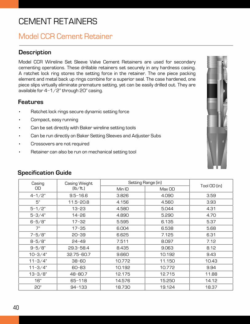
CEMENT RETAINERS
Model CCR Cement Retainer
Description
Model CCR Wireline Set Sleeve Valve Cement Retainers are used for secondary cementing operations. These drillable retainers set securely in any hardness casing. A ratchet lock ring stores the setting force in the retainer. The one piece packing element and metal back up rings combine for a superior seal. The case hardened, one piece slips virtually eliminate premature setting, yet can be easily drilled out. They are available for 4-1/2” through 20” casing.
Specification Guide
CasingOD
Casing Weight(lb/ft.)
Setting Range (in)Tool OD (in)
Min ID Max OD
4-1/2” 9.5-16.6 3.826 4.090 3.59
5” 11.5-20.8 4.156 4.560 3.93
5-1/2” 13-23 4.580 5.044 4.31
5-3/4” 14-26 4.890 5.290 4.70
6-5/8” 17-32 5.595 6.135 5.37
7” 17-35 6.004 6.538 5.68
7-5/8” 20-39 6.625 7.125 6.31
8-5/8” 24-49 7.511 8.097 7.12
9-5/8” 29.3-58.4 8.435 9.063 8.12
10-3/4” 32.75-60.7 9.660 10.192 9.43
11-3/4” 38-60 10.772 11.150 10.43
11-3/4” 60-83 10.192 10.772 9.94
13-3/8” 48-80.7 12.175 12.715 11.88
16” 65-118 14.576 15.250 14.12
20” 94-133 18.730 19.124 18.37
Features
• Ratchet lock rings secure dynamic setting force
• Compact, easy running
• Can be set directly with Baker wireline setting tools
• Can be run directly on Baker Setting Sleeves and Adjuster Subs
• Crossovers are not required
• Retainer can also be run on mechanical setting tool
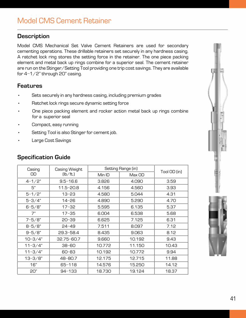
41
Description
Model CMS Mechanical Set Valve Cement Retainers are used for secondary cementing operations. These drillable retainers set securely in any hardness casing. A ratchet lock ring stores the setting force in the retainer. The one piece packing element and metal back up rings combine for a superior seal. The cement retainer are run on the Stinger/Setting Tool providing one trip cost savings. They are available for 4-1/2” through 20” casing.
Features
• Sets securely in any hardness casing, including premium grades
• Ratchet lock rings secure dynamic setting force
• One piece packing element and rocker action metal back up rings combine for a superior seal
• Compact, easy running
• Setting Tool is also Stinger for cement job.
• Large Cost Savings
Model CMS Cement Retainer
CasingOD
Casing Weight(lb/ft.)
Setting Range (in)Tool OD (in)
Min ID Max OD
4-1/2” 9.5-16.6 3.826 4.090 3.59
5” 11.5-20.8 4.156 4.560 3.93
5-1/2” 13-23 4.580 5.044 4.31
5-3/4” 14-26 4.890 5.290 4.70
6-5/8” 17-32 5.595 6.135 5.37
7” 17-35 6.004 6.538 5.68
7-5/8” 20-39 6.625 7.125 6.31
8-5/8” 24-49 7.511 8.097 7.12
9-5/8” 29.3-58.4 8.435 9.063 8.12
10-3/4” 32.75-60.7 9.660 10.192 9.43
11-3/4” 38-60 10.772 11.150 10.43
11-3/4” 60-83 10.192 10.772 9.94
13-3/8” 48-80.7 12.175 12.715 11.88
16” 65-118 14.576 15.250 14.12
20” 94-133 18.730 19.124 18.37
Specification Guide
42
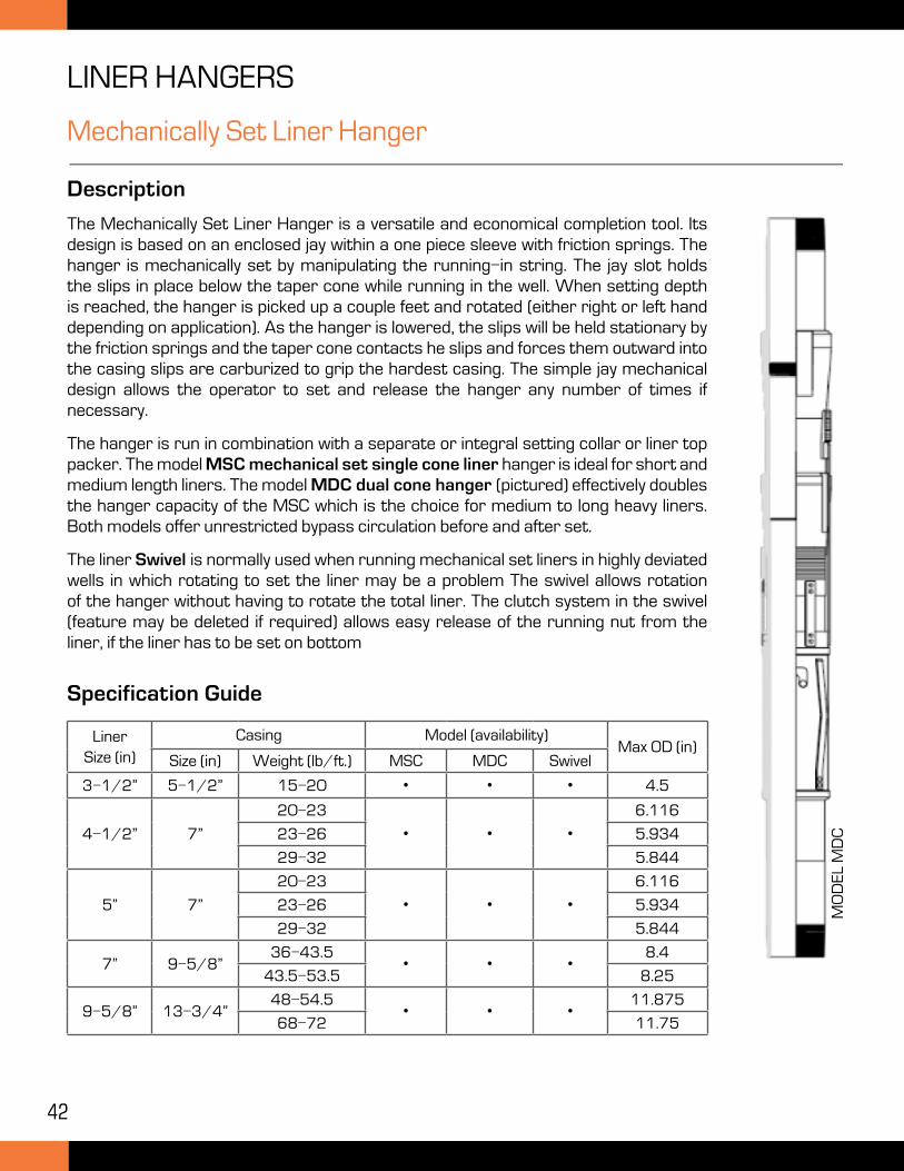
LINER HANGERS
Mechanically Set Liner Hanger
Description
The Mechanically Set Liner Hanger is a versatile and economical completion tool. Its design is based on an enclosed jay within a one piece sleeve with friction springs. The hanger is mechanically set by manipulating the running-in string. The jay slot holds the slips in place below the taper cone while running in the well. When setting depth is reached, the hanger is picked up a couple feet and rotated (either right or left hand depending on application). As the hanger is lowered, the slips will be held stationary by the friction springs and the taper cone contacts he slips and forces them outward into the casing slips are carburized to grip the hardest casing. The simple jay mechanical design allows the operator to set and release the hanger any number of times if necessary.
The hanger is run in combination with a separate or integral setting collar or liner top packer. The model MSC mechanical set single cone liner hanger is ideal for short and medium length liners. The model MDC dual cone hanger (pictured) effectively doubles the hanger capacity of the MSC which is the choice for medium to long heavy liners. Both models offer unrestricted bypass circulation before and after set.
The liner Swivel is normally used when running mechanical set liners in highly deviated wells in which rotating to set the liner may be a problem The swivel allows rotation of the hanger without having to rotate the total liner. The clutch system in the swivel (feature may be deleted if required) allows easy release of the running nut from the liner, if the liner has to be set on bottom
Specification Guide
LinerSize (in)
Casing Model (availability)Max OD (in)
Size (in) Weight (lb/ft.) MSC MDC Swivel
3-1/2” 5-1/2” 15-20 • • • 4.5
4-1/2” 7”
20-23
• • •6.116
23-26 5.934
29-32 5.844
5” 7”
20-23
• • •6.116
23-26 5.934
29-32 5.844
7” 9-5/8”36-43.5
• • •8.4
43.5-53.5 8.25
9-5/8” 13-3/4”48-54.5
• • •11.875
68-72 11.75
MO
DE
L M
DC
43
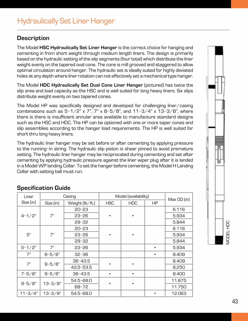
Hydraulically Set Liner Hanger
Description
The Model HSC Hydraulically Set Liner Hanger is the correct choice for hanging and cementing in from short weight through medium length liners. The design is primarily based on the hydraulic setting of the slip segments (four total) which distribute the liner weight evenly on the tapered oval cone. The cone is mill grooved and staggered to allow optimal circulation around hanger. The hydraulic set is ideally suited for highly deviated holes at any depth where liner rotation can not effectively set a mechanical type hanger.
The Model HDC Hydraulically Set Dual Cone Liner Hanger (pictured) has twice the slip area and load capacity as the HSC and is well suited for long heavy liners. Six slips distribute weight evenly on two tapered cones.
The Model HP was specifically designed and developed for challenging liner/casing combinations such as 5-1/2” x 7”, 7” x 8-5/8”, and 11-3/4” x 13-3/8”, where there is there is insufficient annular area available to manufacture standard designs such as the HSC and HDC. The HP can be optioned with one or more taper cones and slip assemblies according to the hanger load requirements. The HP is well suited for short thru long heavy liners.
The hydraulic liner hanger may be set before or after cementing by applying pressure to the running-in string. The hydraulic slip piston is shear pinned to avoid premature setting. The hydraulic liner hanger may be reciprocated during cementing and set after cementing by applying hydraulic pressure against the liner wiper plug after it is landed in a Model WP landing Collar. To set the hanger before cementing, the Model H Landing Collar with setting ball must run.
Specification GuideLiner
Size (in)Casing Model (availability)
Max OD (in)Size (in) Weight (lb/ft.) HSC HDC HP
4-1/2” 7”
20-23
• •6.116
23-26 5.934
29-32 5.844
5” 7”
20-23
• •6.116
23-26 5.934
29-32 5.844
5-1/2” 7” 23-26 • 5.934
7” 8-5/8” 32-36 • 8.409
7” 9-5/8”36-43.5
• •8.409
43.5-53.5 8.250
7-5/8” 9-5/8” 36-43.5 • • 8.400
9-5/8” 13-3/8”54.5-68.0
• •11.875
68-72 11.750
11-3/4” 13-3/8” 54.5-68.0 • 12.063
MO
DE
L H
DC
44
OPEN HOLE PACKERS
Multi-Set Production-Injection Packer
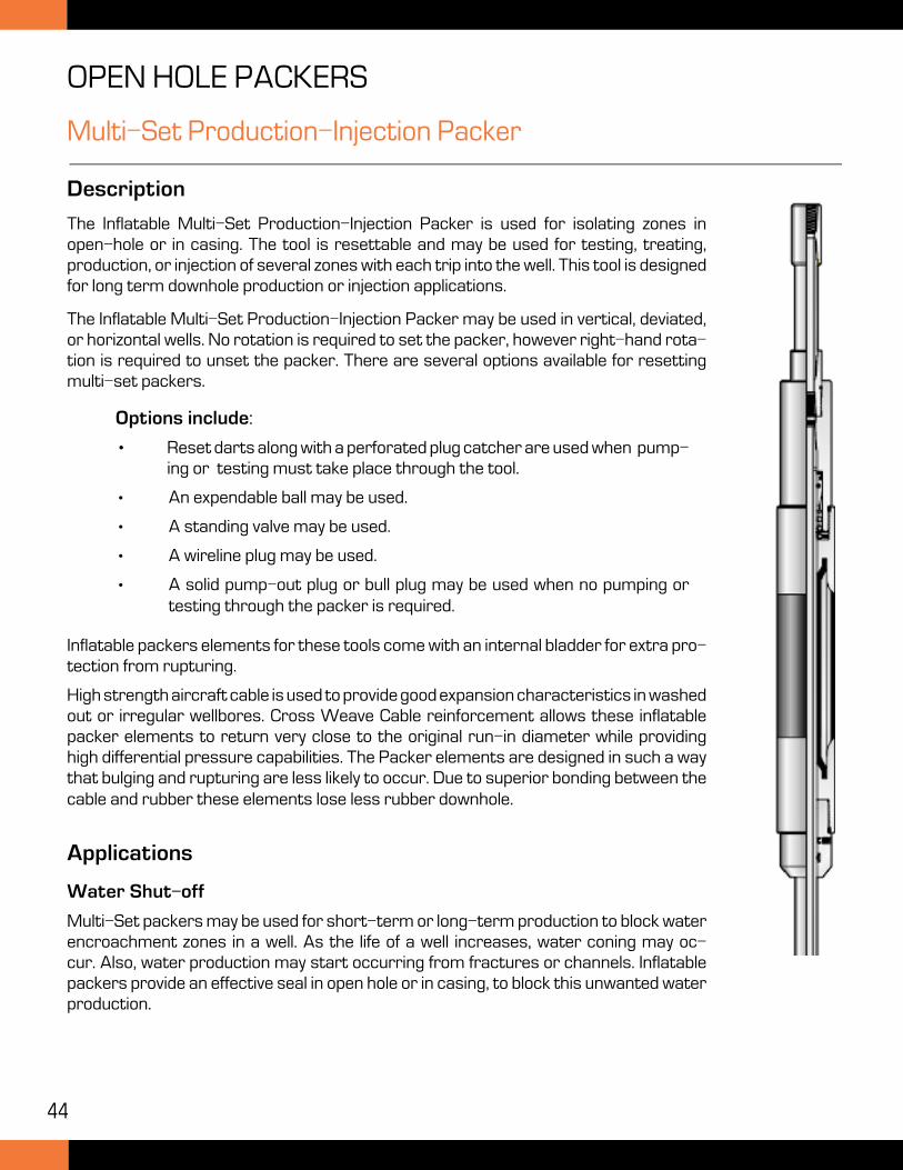
Description
The Inflatable Multi-Set Production-Injection Packer is used for isolating zones in open-hole or in casing. The tool is resettable and may be used for testing, treating, production, or injection of several zones with each trip into the well. This tool is designed for long term downhole production or injection applications.
The Inflatable Multi-Set Production-Injection Packer may be used in vertical, deviated, or horizontal wells. No rotation is required to set the packer, however right-hand rota-tion is required to unset the packer. There are several options available for resetting multi-set packers.
Options include:
• Reset darts along with a perforated plug catcher are used when pump-ing or testing must take place through the tool.
• An expendable ball may be used.
• A standing valve may be used.
• A wireline plug may be used.
• A solid pump-out plug or bull plug may be used when no pumping or testing through the packer is required.
Inflatable packers elements for these tools come with an internal bladder for extra pro-tection from rupturing.
High strength aircraft cable is used to provide good expansion characteristics in washed out or irregular wellbores. Cross Weave Cable reinforcement allows these inflatable packer elements to return very close to the original run-in diameter while providing high differential pressure capabilities. The Packer elements are designed in such a way that bulging and rupturing are less likely to occur. Due to superior bonding between the cable and rubber these elements lose less rubber downhole.
Applications
Water Shut-off
Multi-Set packers may be used for short-term or long-term production to block water encroachment zones in a well. As the life of a well increases, water coning may oc-cur. Also, water production may start occurring from fractures or channels. Inflatable packers provide an effective seal in open hole or in casing, to block this unwanted water production.
45
Multi-Set Production-Injection Packer
Production
Multi-Set Inflatable Packers are also very effective for production applications. The packer serves two purposes when used for these applications. Firstly, the inflatable packer element provides a very effective seal in open hole or in casing. Secondly, the element anchors solidly in open hole or in casing, to prevent tubing rotation or reciprocation at the tool.
Injection
Multi-Set Inflatable Packers may be used for injection of fluids in disposal wells. A large internal bore is provided through the tool. For long term disposal applications it is very important that materials used in manufacturing these tools, are able to resist highly corrosive environments typically associated with disposal wells.
Testing
Multi-Set Inflatable Packers may be used for testing zones in open hole or in casing. Zones may be isolated to determine oil, gas, or water production from certain sections. Testing of each zone will determine which fluid is produced from that section. Also, testing will determine flow rates the zone. Electronic pressure-temperature recorders as well as shut-in tools, may be used with the system to provide additional subsurface data from zones being tested.
Treating
Multi-Set Inflatable Packers may be used for treating zones in open hole or in casing. Typical treatments performed through the tool would be fracturing, acidizing, polymer injection for water shut-off, and acid washes For treating applications, a circulating valve is used above the tool. This valve is opened to allow treatment fluid to be pumped from surface, to the tool. Once the treatment fluid is spotted to the tool, the circulating valve is closed, and treatment fluid is then injected to the zone located below the packer.
Squeeze Cementing
Multi-Set Inflatable Packers may be used for squeeze cementing zones in open hole or in casing. These packers provide greater clearance for running tools into a well where there are restrictions such as casing patches. In addition, the long seal section provided with an inflatable element is more effective in older wells where casing may be partially corroded. These packers are particularly effective for squeeze cementing required to abandon old wells. For squeeze cementing applications, a circulating valve is used above the tool. This valve is opened to allow cement to be circulated from surface, to the tool. Once the cement is spotted at the tool, the circulating valve is closed, and cement is then squeezed into the zone located below the packer.
Pressure Testing Casing Patches
Multi-Set Inflatable Packers are very effective for testing casing patches. Run-in diameter is reduced when a casing patch is set. An inflatable packer is designed with a reduced Outer Diameter (OD), which makes it possible to pass through a casing patch.
46
Open-Hole Straddle Packer System
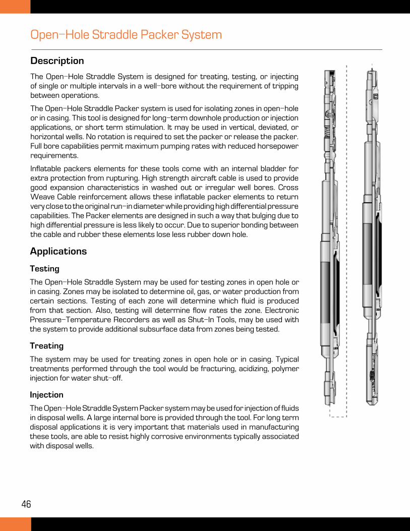
Description
The Open-Hole Straddle System is designed for treating, testing, or injecting of single or multiple intervals in a well-bore without the requirement of tripping between operations.
The Open-Hole Straddle Packer system is used for isolating zones in open-hole or in casing. This tool is designed for long-term downhole production or injection applications, or short term stimulation. It may be used in vertical, deviated, or horizontal wells. No rotation is required to set the packer or release the packer. Full bore capabilities permit maximum pumping rates with reduced horsepower requirements.
Inflatable packers elements for these tools come with an internal bladder for extra protection from rupturing. High strength aircraft cable is used to provide good expansion characteristics in washed out or irregular well bores. Cross Weave Cable reinforcement allows these inflatable packer elements to return very close to the original run-in diameter while providing high differential pressure capabilities. The Packer elements are designed in such a way that bulging due to high differential pressure is less likely to occur. Due to superior bonding between the cable and rubber these elements lose less rubber down hole.
Applications
Testing
The Open-Hole Straddle System may be used for testing zones in open hole or in casing. Zones may be isolated to determine oil, gas, or water production from certain sections. Testing of each zone will determine which fluid is produced from that section. Also, testing will determine flow rates the zone. Electronic Pressure-Temperature Recorders as well as Shut-In Tools, may be used with the system to provide additional subsurface data from zones being tested.
Treating
The system may be used for treating zones in open hole or in casing. Typical treatments performed through the tool would be fracturing, acidizing, polymer injection for water shut-off.
Injection
The Open-Hole Straddle System Packer system may be used for injection of fluids in disposal wells. A large internal bore is provided through the tool. For long term disposal applications it is very important that materials used in manufacturing these tools, are able to resist highly corrosive environments typically associated with disposal wells.
47
Open-Hole Straddle Packer System
For treating applications, a circulating valve is used above the tool. This valve is opened to allow treatment fluid to be pumped from surface, to the tool. Once the treatment fluid is spotted to the tool, the circulating valve is closed, and treatment fluid is then injected to the zone located below the packer.
Operation SequenceAs the Open-Hole Straddle System tool is being run into the hole the tool auto fills due to the large unrestricted bore through the tool which also permits circulation through the tool. Run in position ensures that the packer element remains equalized preventing premature inflation of the packer element.
During the inflation sequence a reset dart or ball is launched from surface and pumped onto the seat. Fluid is then blocked to the annulus and through the packer ID Fluid is then diverted through concentric passages to the inflation channels of the packer element. It is then permissible to increase pressure in even increments allowing the packer element to fully inflate properly. Once the desired differential pressure is reached within the element pressure must be held for 10 minutes to allow the packer element to fully square off.
During the inflation pressure lock-in sequence weight is slacked off onto the tool by shifting the lug mandrel blocks the inflation channels trapping the pressure in the element. Shifting the lug mandrel also blocks ports from the ID of the tool to the annulus.
Once packer seat is verified tubing pressure can be increased to the pre-determined pressure to shear the ball seat or the reset dart. In the case of the re-set dart the dart shears allowing the collets to collapse and pass fully through the tool landing in the dart sub catcher on the bottom of the tool. Fluid is then able to flow through the large unrestricted bore of the tool to below the packer.
Once testing or treating has been finished weight is picked up off the string to begin the deflation sequence. The packer element inflation channels and annulus ports are opened allowing the packer to equalize and deflate close to its original run-in diameter. The tool is now back to its original run-in position ready to be moved to another interval. Additional darts may be pumped from surface providing multiple setting in one trip into the well.
Running Procedures
Setting the Multi-Set Packer
• Run in hole to setting depth at moderate speed. Avoid any sudden stops.
• Take additional care in open hole.
• On depth, establish up weights and down weights. The pipe may be circulated or filled, as required.
• Insert the reset dart into the string. Circulate to depth at 2 bbls./min and reducing to 1/4 bbl/min when within 3-5 bbls of the tool.
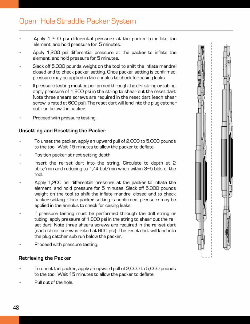
48
Open-Hole Straddle Packer System
• Apply 1,200 psi differential pressure at the packer to inflate the element, and hold pressure for 5 minutes.
• Apply 1,200 psi differential pressure at the packer to inflate the element, and hold pressure for 5 minutes.
• Slack off 5,000 pounds weight on the tool to shift the inflate mandrel closed and to check packer setting. Once packer setting is confirmed, pressure may be applied in the annulus to check for casing leaks.
• If pressure testing must be performed through the drill string or tubing, apply pressure of 1,800 psi in the string to shear out the reset dart. Note three shears screws are required in the reset dart (each shear screw is rated at 600 psi). The reset dart will land into the plug catcher sub run below the packer.
• Proceed with pressure testing.
Unsetting and Resetting the Packer
• To unset the packer, apply an upward pull of 2,000 to 5,000 pounds to the tool. Wait 15 minutes to allow the packer to deflate.
• Position packer at next setting depth.
• Insert the re-set dart into the string. Circulate to depth at 2 bbls/min and reducing to 1/4 bbl/min when within 3-5 bbls of the tool.
• Apply 1,200 psi differential pressure at the packer to inflate the element, and hold pressure for 5 minutes. Slack off 5,000 pounds weight on the tool to shift the inflate mandrel closed and to check packer setting. Once packer setting is confirmed, pressure may be applied in the annulus to check for casing leaks.
• If pressure testing must be performed through the drill string or tubing, apply pressure of 1,800 psi in the string to shear out the re-set dart. Note three shears screws are required in the re¬set dart (each shear screw is rated at 600 psi). The reset dart will land into the plug catcher sub run below the packer.
• Proceed with pressure testing.
Retrieving the Packer
• To unset the packer, apply an upward pull of 2,000 to 5,000 pounds to the tool. Wait 15 minutes to allow the packer to deflate.
• Pull out of the hole.
49
Benefits of the Open-Hole Straddle Packer System
• Highly durable elements, 66 inches in length, with aircraft cable reinforcement, to ensure maximum isolation capabilities in the open-hole, and to the return the element back to original run in diameter.
• Multiple setting, so a number of intervals may be stimulated in the same trip.
• High differential pressure rating for maximum stimulation pressures.
• No tubing rotation required to function the tools making the system very user friendly in deviated well conditions.
• Treatment fluid can be spotted to the tools.
• Ability to test an interval before stimulation, to compare zone production before and after stimulation, and can be used to isolate open hole sections to find pay zones.
• Small packer OD’s to allow tools to be ran in restricted ID wellbores.
Open-Hole Straddle Packer System
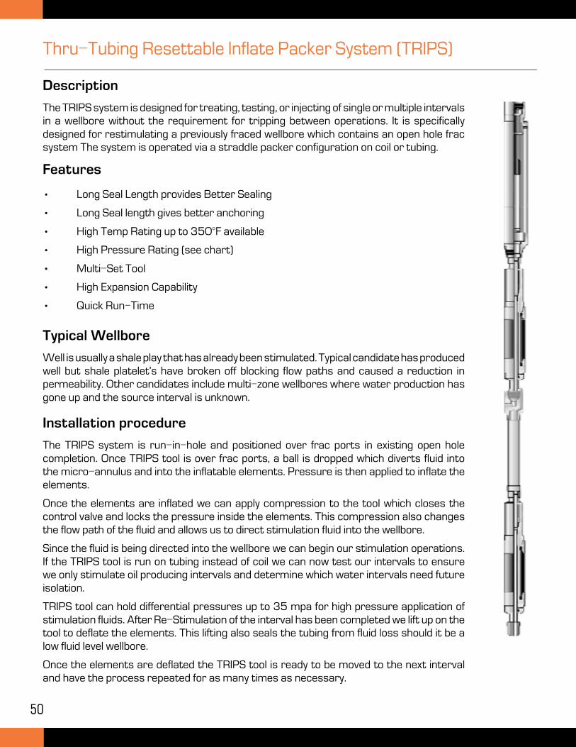
50
Thru-Tubing Resettable Inflate Packer System (TRIPS)
Description
The TRIPS system is designed for treating, testing, or injecting of single or multiple intervals in a wellbore without the requirement for tripping between operations. It is specifically designed for restimulating a previously fraced wellbore which contains an open hole frac system The system is operated via a straddle packer configuration on coil or tubing.
Features
• Long Seal Length provides Better Sealing
• Long Seal length gives better anchoring
• High Temp Rating up to 350°F available
• High Pressure Rating (see chart)
• Multi-Set Tool
• High Expansion Capability
• Quick Run-Time
Typical Wellbore
Well is usually a shale play that has already been stimulated. Typical candidate has produced well but shale platelet’s have broken off blocking flow paths and caused a reduction in permeability. Other candidates include multi-zone wellbores where water production has gone up and the source interval is unknown.
Installation procedure
The TRIPS system is run-in-hole and positioned over frac ports in existing open hole completion. Once TRIPS tool is over frac ports, a ball is dropped which diverts fluid into the micro-annulus and into the inflatable elements. Pressure is then applied to inflate the elements.
Once the elements are inflated we can apply compression to the tool which closes the control valve and locks the pressure inside the elements. This compression also changes the flow path of the fluid and allows us to direct stimulation fluid into the wellbore.
Since the fluid is being directed into the wellbore we can begin our stimulation operations. If the TRIPS tool is run on tubing instead of coil we can now test our intervals to ensure we only stimulate oil producing intervals and determine which water intervals need future isolation.
TRIPS tool can hold differential pressures up to 35 mpa for high pressure application of stimulation fluids. After Re-Stimulation of the interval has been completed we lift up on the tool to deflate the elements. This lifting also seals the tubing from fluid loss should it be a low fluid level wellbore.
Once the elements are deflated the TRIPS tool is ready to be moved to the next interval and have the process repeated for as many times as necessary.
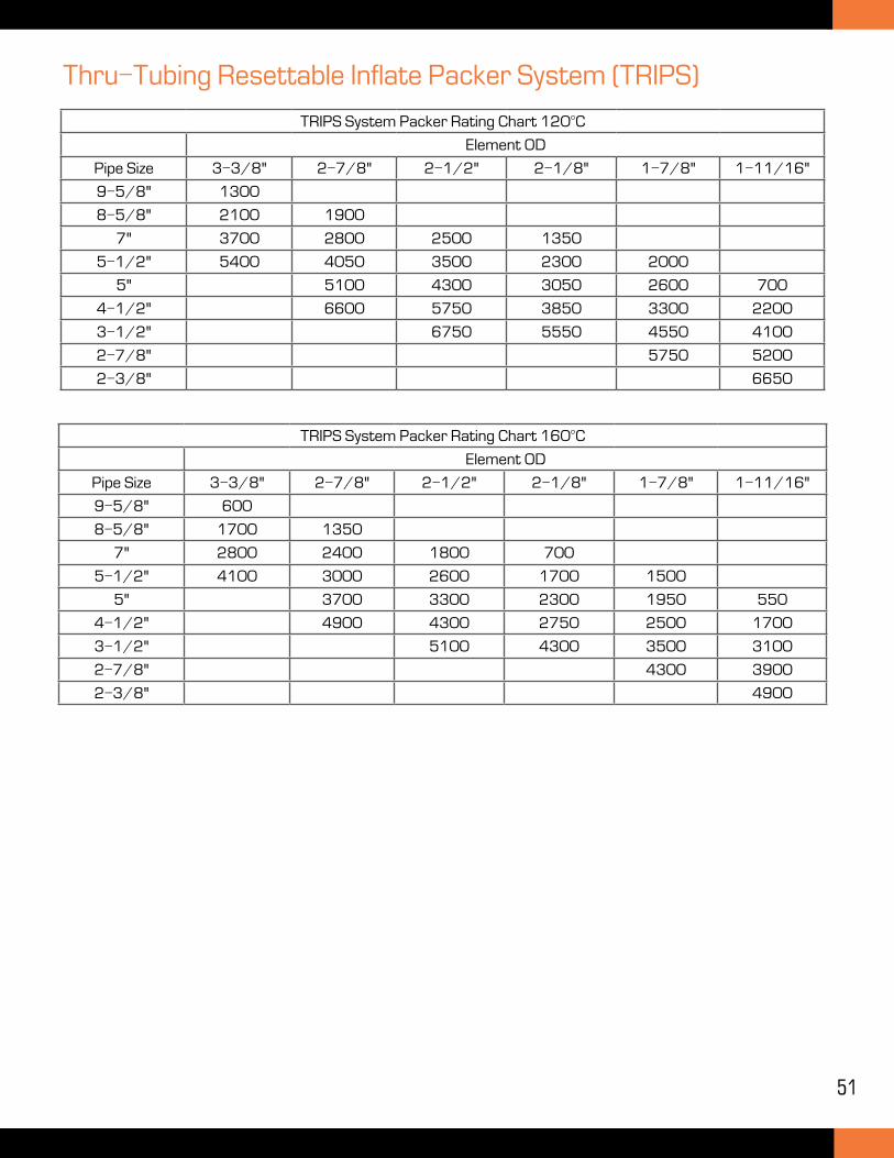
51
Thru-Tubing Resettable Inflate Packer System (TRIPS)
TRIPS System Packer Rating Chart 120°C
Element OD
Pipe Size 3-3/8" 2-7/8" 2-1/2" 2-1/8" 1-7/8" 1-11/16"
9-5/8" 1300
8-5/8" 2100 1900
7" 3700 2800 2500 1350
5-1/2" 5400 4050 3500 2300 2000
5" 5100 4300 3050 2600 700
4-1/2" 6600 5750 3850 3300 2200
3-1/2" 6750 5550 4550 4100
2-7/8" 5750 5200
2-3/8" 6650
TRIPS System Packer Rating Chart 160°C
Element OD
Pipe Size 3-3/8" 2-7/8" 2-1/2" 2-1/8" 1-7/8" 1-11/16"
9-5/8" 600
8-5/8" 1700 1350
7" 2800 2400 1800 700
5-1/2" 4100 3000 2600 1700 1500
5" 3700 3300 2300 1950 550
4-1/2" 4900 4300 2750 2500 1700
3-1/2" 5100 4300 3500 3100
2-7/8" 4300 3900
2-3/8" 4900
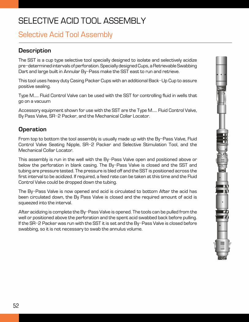
52
Selective Acid Tool Assembly
Description
The SST is a cup type selective tool specially designed to isolate and selectively acidize pre-determined intervals of perforation. Specially designed Cups, a Retrievable Swabbing Dart and large built in Annular By-Pass make the SST east to run and retrieve.
This tool uses heavy duty Casing Packer Cups with an additional Back-Up Cup to assure positive sealing.
Type M..... Fluid Control Valve can be used with the SST for controlling fluid in wells that go on a vacuum
Accessory equipment shown for use with the SST are the Type M..... Fluid Control Valve, By Pass Valve, SR-2 Packer, and the Mechanical Collar Locator.
Operation
From top to bottom the tool assembly is usually made up with the By-Pass Valve, Fluid Control Valve Seating Nipple, SR-2 Packer and Selective Stimulation Tool, and the Mechanical Collar Locator.
This assembly is run in the well with the By-Pass Valve open and positioned above or below the perforation in blank casing. The By-Pass Valve is closed and the SST and tubing are pressure tested. The pressure is bled off and the SST is positioned across the first interval to be acidized. If required, a feed rate can be taken at this time and the Fluid Control Valve could be dropped down the tubing.
The By-Pass Valve is now opened and acid is circulated to bottom After the acid has been circulated down, the By Pass Valve is closed and the required amount of acid is squeezed into the interval.
After acidizing is complete the By-Pass Valve is opened. The tools can be pulled from the well or positioned above the perforation and the spent acid swabbed back before pulling. If the SR-2 Packer was run with the SST it is set and the By-Pass Valve is closed before swabbing, so it is not necessary to swab the annulus volume.
SELECTIVE ACID TOOL ASSEMBLY
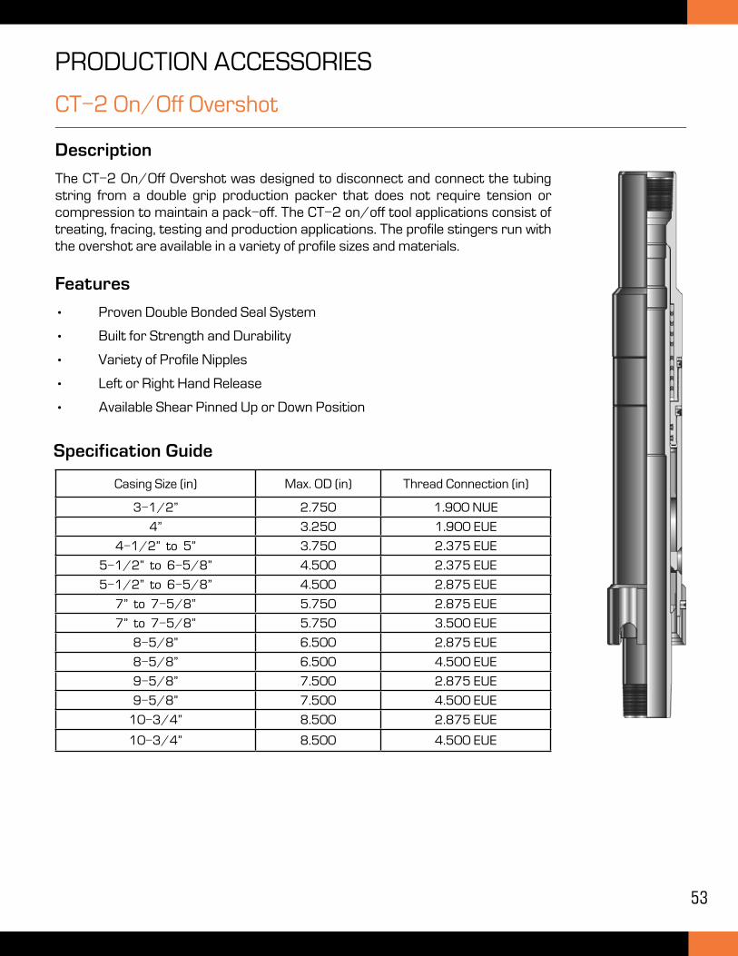
53
CT-2 On/Off Overshot
Description
The CT-2 On/Off Overshot was designed to disconnect and connect the tubing string from a double grip production packer that does not require tension or compression to maintain a pack-off. The CT-2 on/off tool applications consist of treating, fracing, testing and production applications. The profile stingers run with the overshot are available in a variety of profile sizes and materials.
Features
• Proven Double Bonded Seal System
• Built for Strength and Durability
• Variety of Profile Nipples
• Left or Right Hand Release
• Available Shear Pinned Up or Down Position
PRODUCTION ACCESSORIES
Specification Guide
Casing Size (in) Max. OD (in) Thread Connection (in)
3-1/2” 2.750 1.900 NUE
4” 3.250 1.900 EUE
4-1/2” to 5” 3.750 2.375 EUE
5-1/2” to 6-5/8” 4.500 2.375 EUE
5-1/2” to 6-5/8” 4.500 2.875 EUE
7” to 7-5/8” 5.750 2.875 EUE
7” to 7-5/8” 5.750 3.500 EUE
8-5/8” 6.500 2.875 EUE
8-5/8” 6.500 4.500 EUE
9-5/8” 7.500 2.875 EUE
9-5/8” 7.500 4.500 EUE
10-3/4” 8.500 2.875 EUE
10-3/4” 8.500 4.500 EUE
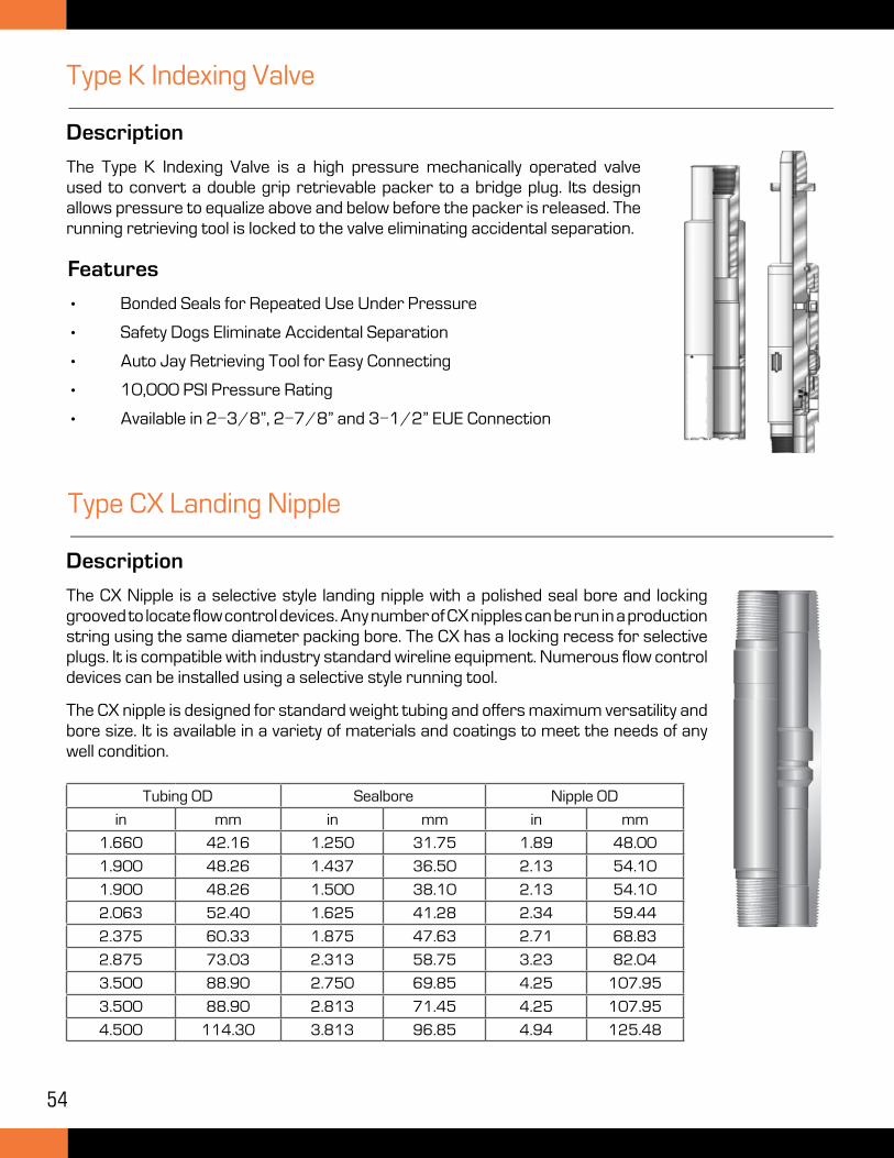
54
Type K Indexing Valve
Description
The Type K Indexing Valve is a high pressure mechanically operated valve used to convert a double grip retrievable packer to a bridge plug. Its design allows pressure to equalize above and below before the packer is released. The running retrieving tool is locked to the valve eliminating accidental separation.
Features
• Bonded Seals for Repeated Use Under Pressure
• Safety Dogs Eliminate Accidental Separation
• Auto Jay Retrieving Tool for Easy Connecting
• 10,000 PSI Pressure Rating
• Available in 2-3/8”, 2-7/8” and 3-1/2” EUE Connection
Type CX Landing Nipple
Description
The CX Nipple is a selective style landing nipple with a polished seal bore and locking grooved to locate flow control devices. Any number of CX nipples can be run in a production string using the same diameter packing bore. The CX has a locking recess for selective plugs. It is compatible with industry standard wireline equipment. Numerous flow control devices can be installed using a selective style running tool.
The CX nipple is designed for standard weight tubing and offers maximum versatility and bore size. It is available in a variety of materials and coatings to meet the needs of any well condition.
Tubing OD Sealbore Nipple OD
in mm in mm in mm
1.660 42.16 1.250 31.75 1.89 48.00
1.900 48.26 1.437 36.50 2.13 54.10
1.900 48.26 1.500 38.10 2.13 54.10
2.063 52.40 1.625 41.28 2.34 59.44
2.375 60.33 1.875 47.63 2.71 68.83
2.875 73.03 2.313 58.75 3.23 82.04
3.500 88.90 2.750 69.85 4.25 107.95
3.500 88.90 2.813 71.45 4.25 107.95
4.500 114.30 3.813 96.85 4.94 125.48
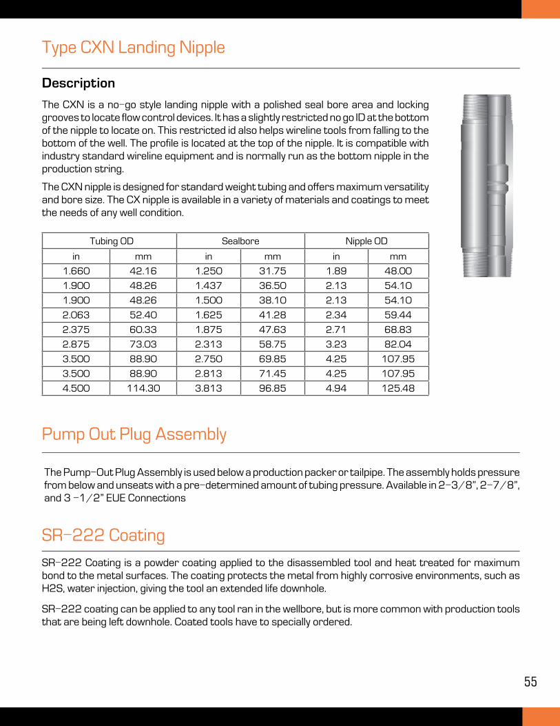
55
Type CXN Landing Nipple
Description
The CXN is a no-go style landing nipple with a polished seal bore area and locking grooves to locate flow control devices. It has a slightly restricted no go ID at the bottom of the nipple to locate on. This restricted id also helps wireline tools from falling to the bottom of the well. The profile is located at the top of the nipple. It is compatible with industry standard wireline equipment and is normally run as the bottom nipple in the production string.
The CXN nipple is designed for standard weight tubing and offers maximum versatility and bore size. The CX nipple is available in a variety of materials and coatings to meet the needs of any well condition.
Tubing OD Sealbore Nipple OD
in mm in mm in mm
1.660 42.16 1.250 31.75 1.89 48.00
1.900 48.26 1.437 36.50 2.13 54.10
1.900 48.26 1.500 38.10 2.13 54.10
2.063 52.40 1.625 41.28 2.34 59.44
2.375 60.33 1.875 47.63 2.71 68.83
2.875 73.03 2.313 58.75 3.23 82.04
3.500 88.90 2.750 69.85 4.25 107.95
3.500 88.90 2.813 71.45 4.25 107.95
4.500 114.30 3.813 96.85 4.94 125.48
Pump Out Plug Assembly
SR-222 Coating
SR-222 Coating is a powder coating applied to the disassembled tool and heat treated for maximum bond to the metal surfaces. The coating protects the metal from highly corrosive environments, such as H2S, water injection, giving the tool an extended life downhole.
SR-222 coating can be applied to any tool ran in the wellbore, but is more common with production tools that are being left downhole. Coated tools have to specially ordered.
The Pump-Out Plug Assembly is used below a production packer or tailpipe. The assembly holds pressure from below and unseats with a pre-determined amount of tubing pressure. Available in 2-3/8”, 2-7/8”, and 3 -1/2” EUE Connections
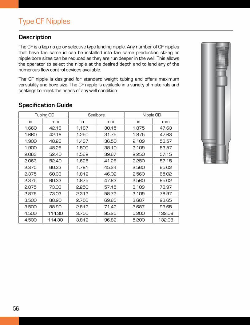
56
Type CF Nipples
Description
The CF is a top no go or selective type landing nipple. Any number of CF nipples that have the same id can be installed into the same production string or nipple bore sizes can be reduced as they are run deeper in the well. This allows the operator to select the nipple at the desired depth and to land any of the numerous flow control devices available.
The CF nipple is designed for standard weight tubing and offers maximum versatility and bore size. The CF nipple is available in a variety of materials and coatings to meet the needs of any well condition.
Tubing OD Sealbore Nipple OD
in mm in mm in mm
1.660 42.16 1.187 30.15 1.875 47.63
1.660 42.16 1.250 31.75 1.875 47.63
1.900 48.26 1.437 36.50 2.109 53.57
1.900 48.26 1.500 38.10 2.109 53.57
2.063 52.40 1.562 39.67 2.250 57.15
2.063 52.40 1.625 41.28 2.250 57.15
2.375 60.33 1.781 45.24 2.560 65.02
2.375 60.33 1.812 46.02 2.560 65.02
2.375 60.33 1.875 47.63 2.560 65.02
2.875 73.03 2.250 57.15 3.109 78.97
2.875 73.03 2.312 58.72 3.109 78.97
3.500 88.90 2.750 69.85 3.687 93.65
3.500 88.90 2.812 71.42 3.687 93.65
4.500 114.30 3.750 95.25 5.200 132.08
4.500 114.30 3.812 96.82 5.200 132.08
Specification Guide
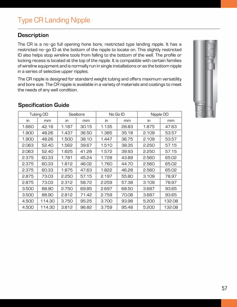
57
Type CR Landing Nipple
Description
The CR is a no-go full opening hone bore, restricted type landing nipple. It has a restricted no-go ID at the bottom of the nipple to locate on. This slightly restricted ID also helps stop wireline tools from falling to the bottom of the well. The profile or locking recess is located at the top of the nipple. It is compatible with certain families of wireline equipment and is normally run in single installations or as the bottom nipple in a series of selective upper nipples.
The CR nipple is designed for standard weight tubing and offers maximum versatility and bore size. The CR nipple is available in a variety of materials and coatings to meet the needs of any well condition.
Tubing OD Sealbore No Go ID Nipple OD
in mm in mm in mm in mm
1.660 42.16 1.187 30.15 1.135 28.83 1.875 47.63
1.900 48.26 1.437 36.50 1.385 35.18 2.109 53.57
1.900 48.26 1.500 38.10 1.447 36.75 2.109 53.57
2.063 52.40 1.562 39.67 1.510 38.35 2.250 57.15
2.063 52.40 1.625 41.28 1.572 39.93 2.250 57.15
2.375 60.33 1.781 45.24 1.728 43.89 2.560 65.02
2.375 60.33 1.812 46.02 1.760 44.70 2.560 65.02
2.375 60.33 1.875 47.63 1.822 46.28 2.560 65.02
2.875 73.03 2.250 57.15 2.197 55.80 3.109 78.97
2.875 73.03 2.312 58.72 2.259 57.38 3.109 78.97
3.500 88.90 2.750 69.85 2.697 68.50 3.687 93.65
3.500 88.90 2.812 71.42 2.759 70.08 3.687 93.65
4.500 114.30 3.750 95.25 3.700 93.98 5.200 132.08
4.500 114.30 3.812 96.82 3.759 95.48 5.200 132.08
Specification Guide
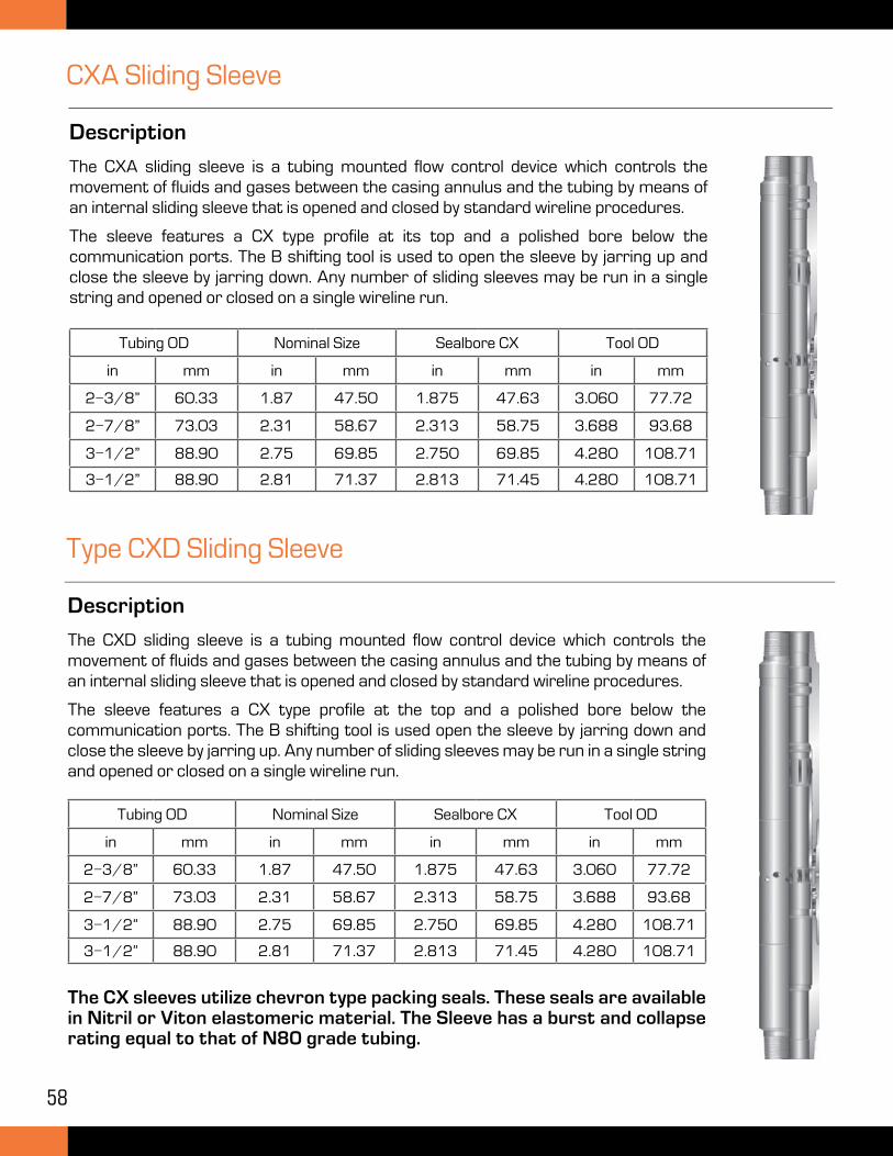
58
CXA Sliding Sleeve
Description
The CXA sliding sleeve is a tubing mounted flow control device which controls the movement of fluids and gases between the casing annulus and the tubing by means of an internal sliding sleeve that is opened and closed by standard wireline procedures.
The sleeve features a CX type profile at its top and a polished bore below the communication ports. The B shifting tool is used to open the sleeve by jarring up and close the sleeve by jarring down. Any number of sliding sleeves may be run in a single string and opened or closed on a single wireline run.
Type CXD Sliding Sleeve
Description
The CXD sliding sleeve is a tubing mounted flow control device which controls the movement of fluids and gases between the casing annulus and the tubing by means of an internal sliding sleeve that is opened and closed by standard wireline procedures.
The sleeve features a CX type profile at the top and a polished bore below the communication ports. The B shifting tool is used open the sleeve by jarring down and close the sleeve by jarring up. Any number of sliding sleeves may be run in a single string and opened or closed on a single wireline run.
Tubing OD Nominal Size Sealbore CX Tool OD
in mm in mm in mm in mm
2-3/8” 60.33 1.87 47.50 1.875 47.63 3.060 77.72
2-7/8” 73.03 2.31 58.67 2.313 58.75 3.688 93.68
3-1/2” 88.90 2.75 69.85 2.750 69.85 4.280 108.71
3-1/2” 88.90 2.81 71.37 2.813 71.45 4.280 108.71
The CX sleeves utilize chevron type packing seals. These seals are available in Nitril or Viton elastomeric material. The Sleeve has a burst and collapse rating equal to that of N80 grade tubing.
Tubing OD Nominal Size Sealbore CX Tool OD
in mm in mm in mm in mm
2-3/8” 60.33 1.87 47.50 1.875 47.63 3.060 77.72
2-7/8” 73.03 2.31 58.67 2.313 58.75 3.688 93.68
3-1/2” 88.90 2.75 69.85 2.750 69.85 4.280 108.71
3-1/2” 88.90 2.81 71.37 2.813 71.45 4.280 108.71
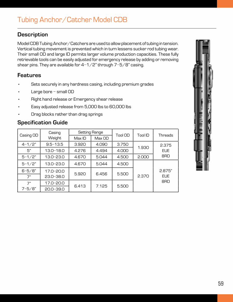
59
Tubing Anchor/Catcher Model CDB
Description
Model CDB Tubing Anchor/Catchers are used to allow placement of tubing in tension. Vertical tubing movement is prevented which in turn lessens sucker rod tubing wear. Their small OD and large ID permits larger volume production capacities. These fully retrievable tools can be easily adjusted for emergency release by adding or removing shear pins. They are available for 4-1/2” through 7-5/8” casing.
Features
• Sets securely in any hardness casing, including premium grades
• Large bore - small OD
• Right hand release or Emergency shear release
• Easy adjusted release from 5,000 lbs to 60,000 lbs
• Drag blocks rather than drag springs
Casing ODCasing Weight
Setting RangeTool OD Tool ID Threads
Max ID Max OD
4-1/2” 9.5-13.5 3.920 4.090 3.7501.930
2.375 EUE8RD
5” 13.0-18.0 4.276 4.494 4.000
5-1/2” 13.0-23.0 4.670 5.044 4.500 2.000
5-1/2” 13.0-23.0 4.670 5.044 4.500
2.3702.875”
EUE8RD
6-5/8” 17.0-20.023.0-38.0
5.920 6.456 5.5007”
7” 7-5/8”
17.0-20.06.413 7.125 5.500
20.0-39.0
Specification Guide
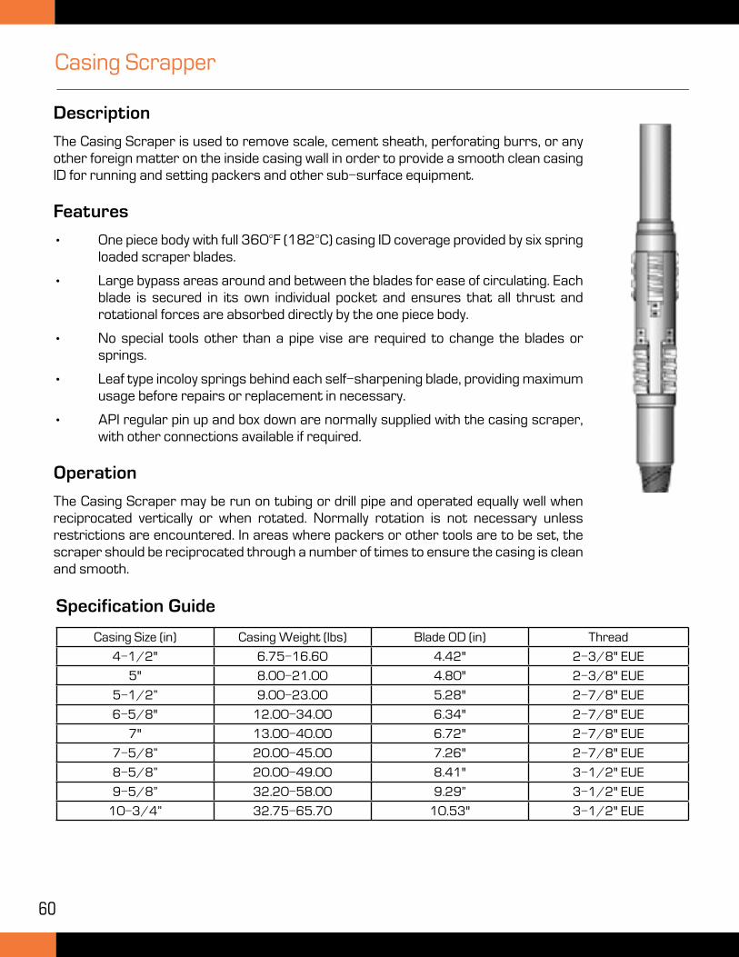
60
Casing Scrapper
Description
The Casing Scraper is used to remove scale, cement sheath, perforating burrs, or any other foreign matter on the inside casing wall in order to provide a smooth clean casing ID for running and setting packers and other sub-surface equipment.
Features
• One piece body with full 360°F (182°C) casing ID coverage provided by six spring loaded scraper blades.
• Large bypass areas around and between the blades for ease of circulating. Each blade is secured in its own individual pocket and ensures that all thrust and rotational forces are absorbed directly by the one piece body.
• No special tools other than a pipe vise are required to change the blades or springs.
• Leaf type incoloy springs behind each self-sharpening blade, providing maximum usage before repairs or replacement in necessary.
• API regular pin up and box down are normally supplied with the casing scraper, with other connections available if required.
Operation
The Casing Scraper may be run on tubing or drill pipe and operated equally well when reciprocated vertically or when rotated. Normally rotation is not necessary unless restrictions are encountered. In areas where packers or other tools are to be set, the scraper should be reciprocated through a number of times to ensure the casing is clean and smooth.
Specification Guide
Casing Size (in) Casing Weight (lbs) Blade OD (in) Thread
4-1/2" 6.75-16.60 4.42" 2-3/8" EUE
5" 8.00-21.00 4.80" 2-3/8" EUE
5-1/2” 9.00-23.00 5.28" 2-7/8" EUE
6-5/8" 12.00-34.00 6.34" 2-7/8" EUE
7" 13.00-40.00 6.72" 2-7/8" EUE
7-5/8” 20.00-45.00 7.26" 2-7/8" EUE
8-5/8” 20.00-49.00 8.41" 3-1/2" EUE
9-5/8” 32.20-58.00 9.29” 3-1/2" EUE
10-3/4” 32.75-65.70 10.53" 3-1/2" EUE
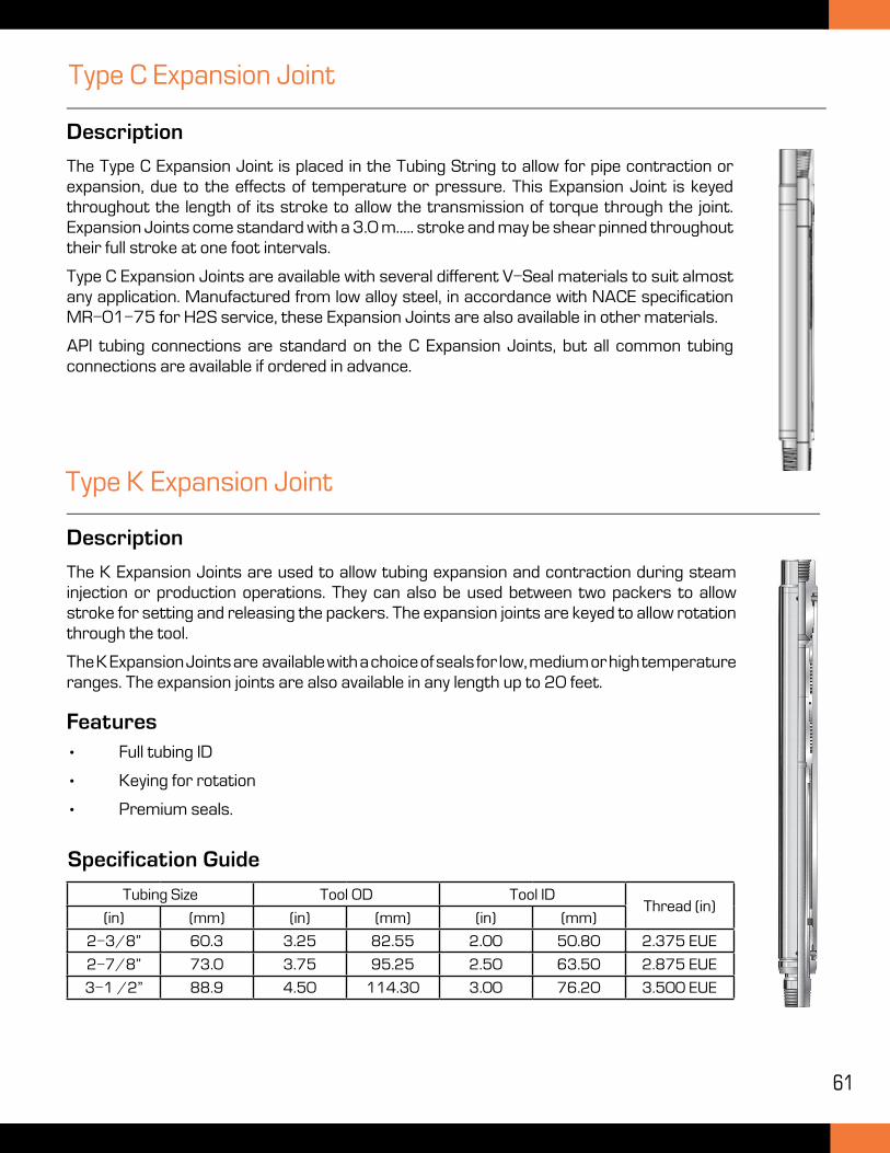
61
Type C Expansion Joint
Description
The Type C Expansion Joint is placed in the Tubing String to allow for pipe contraction or expansion, due to the effects of temperature or pressure. This Expansion Joint is keyed throughout the length of its stroke to allow the transmission of torque through the joint. Expansion Joints come standard with a 3.0 m..... stroke and may be shear pinned throughout their full stroke at one foot intervals.
Type C Expansion Joints are available with several different V-Seal materials to suit almost any application. Manufactured from low alloy steel, in accordance with NACE specification MR-01-75 for H2S service, these Expansion Joints are also available in other materials.
API tubing connections are standard on the C Expansion Joints, but all common tubing connections are available if ordered in advance.
Type K Expansion Joint
Description
The K Expansion Joints are used to allow tubing expansion and contraction during steam injection or production operations. They can also be used between two packers to allow stroke for setting and releasing the packers. The expansion joints are keyed to allow rotation through the tool.
The K Expansion Joints are available with a choice of seals for low, medium or high temperature ranges. The expansion joints are also available in any length up to 20 feet.
Features• Full tubing ID
• Keying for rotation
• Premium seals.
Tubing Size Tool OD Tool IDThread (in)
(in) (mm) (in) (mm) (in) (mm)
2-3/8” 60.3 3.25 82.55 2.00 50.80 2.375 EUE
2-7/8” 73.0 3.75 95.25 2.50 63.50 2.875 EUE
3-1 /2” 88.9 4.50 114.30 3.00 76.20 3.500 EUE
Specification Guide
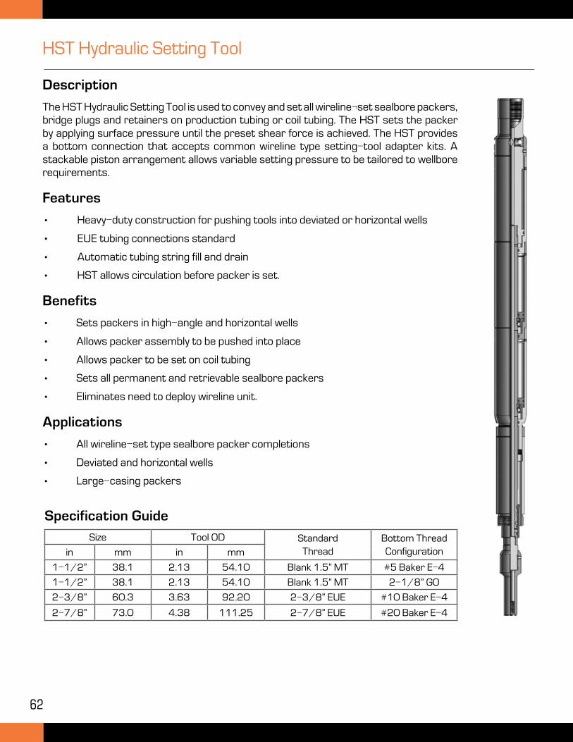
62
HST Hydraulic Setting Tool
Description
The HST Hydraulic Setting Tool is used to convey and set all wireline¬set sealbore packers, bridge plugs and retainers on production tubing or coil tubing. The HST sets the packer by applying surface pressure until the preset shear force is achieved. The HST provides a bottom connection that accepts common wireline type setting-tool adapter kits. A stackable piston arrangement allows variable setting pressure to be tailored to wellbore requirements.
Features
• Heavy-duty construction for pushing tools into deviated or horizontal wells
• EUE tubing connections standard
• Automatic tubing string fill and drain
• HST allows circulation before packer is set.
Benefits
• Sets packers in high-angle and horizontal wells
• Allows packer assembly to be pushed into place
• Allows packer to be set on coil tubing
• Sets all permanent and retrievable sealbore packers
• Eliminates need to deploy wireline unit.
Applications
• All wireline-set type sealbore packer completions
• Deviated and horizontal wells
• Large-casing packers
Specification Guide
Size Tool OD StandardThread
Bottom Thread Configurationin mm in mm
1-1/2” 38.1 2.13 54.10 Blank 1.5” MT #5 Baker E-4
1-1/2” 38.1 2.13 54.10 Blank 1.5” MT 2-1/8” GO
2-3/8” 60.3 3.63 92.20 2-3/8” EUE #10 Baker E-4
2-7/8” 73.0 4.38 111.25 2-7/8” EUE #20 Baker E-4
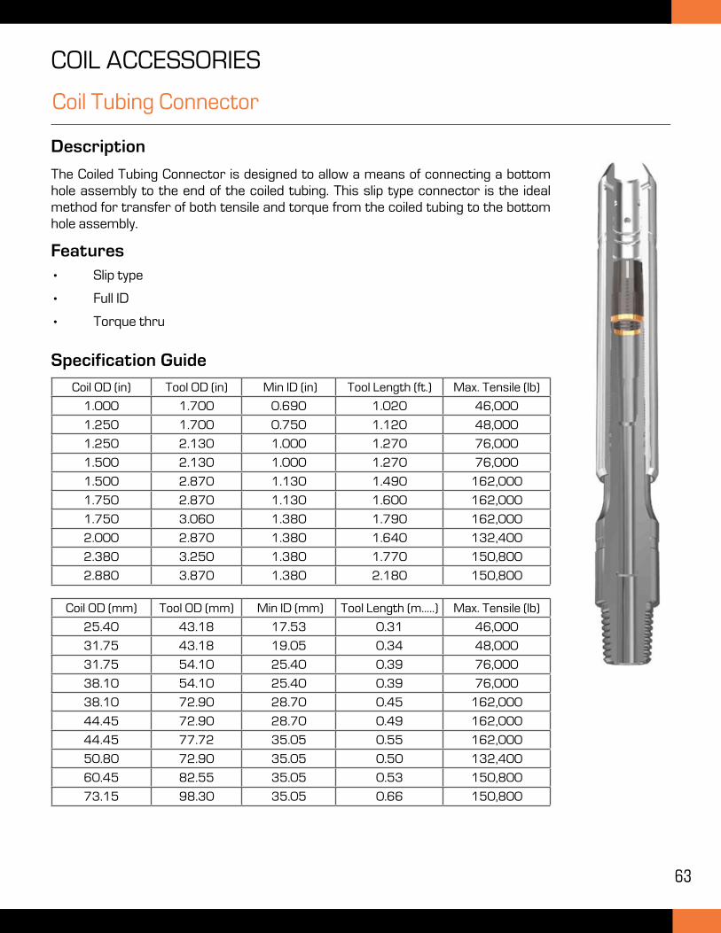
63
Coil Tubing Connector
Description
The Coiled Tubing Connector is designed to allow a means of connecting a bottom hole assembly to the end of the coiled tubing. This slip type connector is the ideal method for transfer of both tensile and torque from the coiled tubing to the bottom hole assembly.
Features
• Slip type
• Full ID
• Torque thru
COIL ACCESSORIES
Specification Guide
Coil OD (in) Tool OD (in) Min ID (in) Tool Length (ft.) Max. Tensile (lb)
1.000 1.700 0.690 1.020 46,000
1.250 1.700 0.750 1.120 48,000
1.250 2.130 1.000 1.270 76,000
1.500 2.130 1.000 1.270 76,000
1.500 2.870 1.130 1.490 162,000
1.750 2.870 1.130 1.600 162,000
1.750 3.060 1.380 1.790 162,000
2.000 2.870 1.380 1.640 132,400
2.380 3.250 1.380 1.770 150,800
2.880 3.870 1.380 2.180 150,800
Coil OD (mm) Tool OD (mm) Min ID (mm) Tool Length (m.....) Max. Tensile (lb)
25.40 43.18 17.53 0.31 46,000
31.75 43.18 19.05 0.34 48,000
31.75 54.10 25.40 0.39 76,000
38.10 54.10 25.40 0.39 76,000
38.10 72.90 28.70 0.45 162,000
44.45 72.90 28.70 0.49 162,000
44.45 77.72 35.05 0.55 162,000
50.80 72.90 35.05 0.50 132,400
60.45 82.55 35.05 0.53 150,800
73.15 98.30 35.05 0.66 150,800
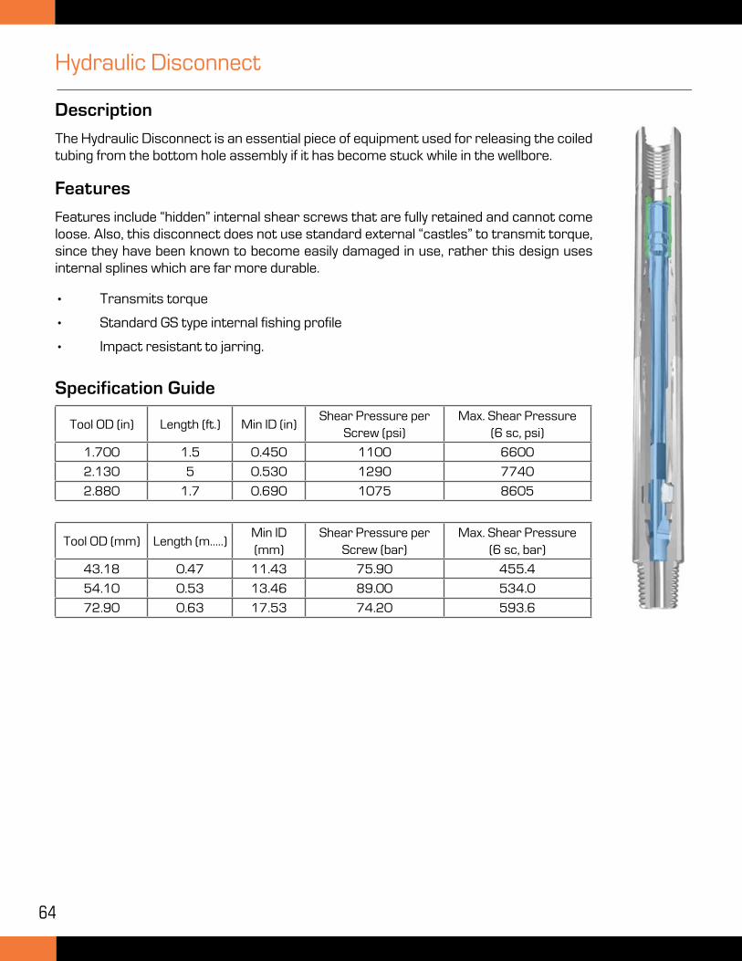
64
Hydraulic Disconnect
Description
The Hydraulic Disconnect is an essential piece of equipment used for releasing the coiled tubing from the bottom hole assembly if it has become stuck while in the wellbore.
Features
Features include “hidden” internal shear screws that are fully retained and cannot come loose. Also, this disconnect does not use standard external “castles” to transmit torque, since they have been known to become easily damaged in use, rather this design uses internal splines which are far more durable.
• Transmits torque
• Standard GS type internal fishing profile
• Impact resistant to jarring.
Specification Guide
Tool OD (mm) Length (m.....)Min ID (mm)
Shear Pressure per Screw (bar)
Max. Shear Pressure (6 sc, bar)
43.18 0.47 11.43 75.90 455.4
54.10 0.53 13.46 89.00 534.0
72.90 0.63 17.53 74.20 593.6
Tool OD (in) Length (ft.) Min ID (in)Shear Pressure per
Screw (psi)Max. Shear Pressure
(6 sc, psi)
1.700 1.5 0.450 1100 6600
2.130 5 0.530 1290 7740
2.880 1.7 0.690 1075 8605
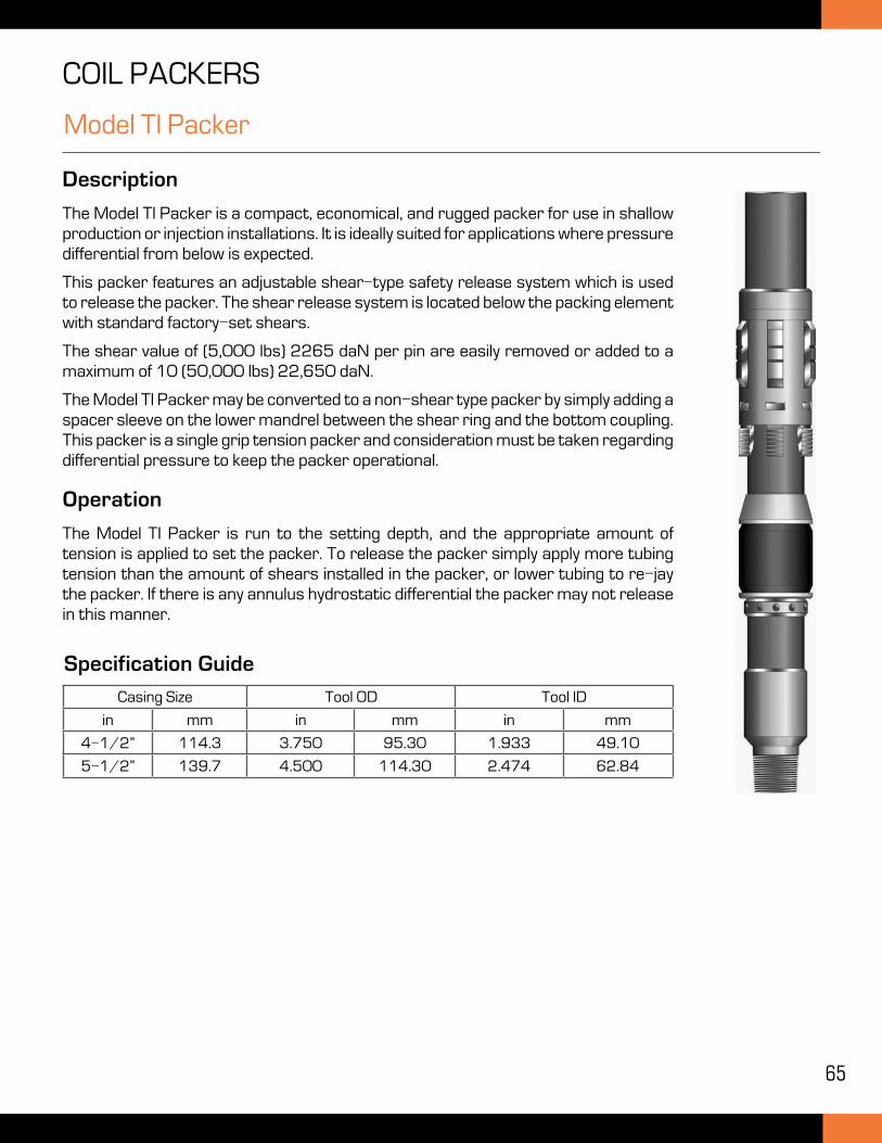
65
Model TI Packer
Description
The Model TI Packer is a compact, economical, and rugged packer for use in shallow production or injection installations. It is ideally suited for applications where pressure differential from below is expected.
This packer features an adjustable shear-type safety release system which is used to release the packer. The shear release system is located below the packing element with standard factory-set shears.
The shear value of (5,000 lbs) 2265 daN per pin are easily removed or added to a maximum of 10 (50,000 lbs) 22,650 daN.
The Model TI Packer may be converted to a non-shear type packer by simply adding a spacer sleeve on the lower mandrel between the shear ring and the bottom coupling. This packer is a single grip tension packer and consideration must be taken regarding differential pressure to keep the packer operational.
Operation
The Model TI Packer is run to the setting depth, and the appropriate amount of tension is applied to set the packer. To release the packer simply apply more tubing tension than the amount of shears installed in the packer, or lower tubing to re-jay the packer. If there is any annulus hydrostatic differential the packer may not release in this manner.
COIL PACKERS
Specification Guide
Casing Size Tool OD Tool ID
in mm in mm in mm
4-1/2” 114.3 3.750 95.30 1.933 49.10
5-1/2” 139.7 4.500 114.30 2.474 62.84
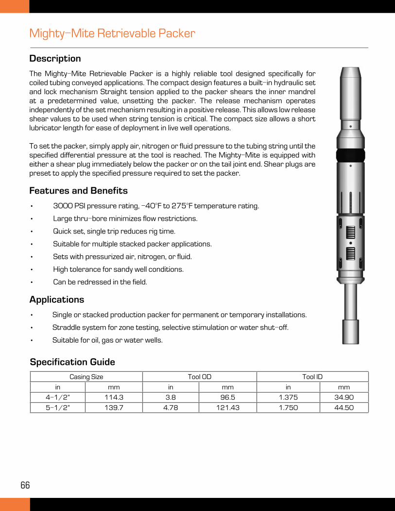
66
Mighty-Mite Retrievable Packer
Description
The Mighty-Mite Retrievable Packer is a highly reliable tool designed specifically for coiled tubing conveyed applications. The compact design features a built-in hydraulic set and lock mechanism Straight tension applied to the packer shears the inner mandrel at a predetermined value, unsetting the packer. The release mechanism operates independently of the set mechanism resulting in a positive release. This allows low release shear values to be used when string tension is critical. The compact size allows a short lubricator length for ease of deployment in live well operations.
To set the packer, simply apply air, nitrogen or fluid pressure to the tubing string until the specified differential pressure at the tool is reached. The Mighty-Mite is equipped with either a shear plug immediately below the packer or on the tail joint end. Shear plugs are preset to apply the specified pressure required to set the packer.
Features and Benefits
• 3000 PSI pressure rating, -40°F to 275°F temperature rating.
• Large thru-bore minimizes flow restrictions.
• Quick set, single trip reduces rig time.
• Suitable for multiple stacked packer applications.
• Sets with pressurized air, nitrogen, or fluid.
• High tolerance for sandy well conditions.
• Can be redressed in the field.
Applications
• Single or stacked production packer for permanent or temporary installations.
• Straddle system for zone testing, selective stimulation or water shut-off.
• Suitable for oil, gas or water wells.
Specification Guide
Casing Size Tool OD Tool ID
in mm in mm in mm
4-1/2” 114.3 3.8 96.5 1.375 34.90
5-1/2” 139.7 4.78 121.43 1.750 44.50
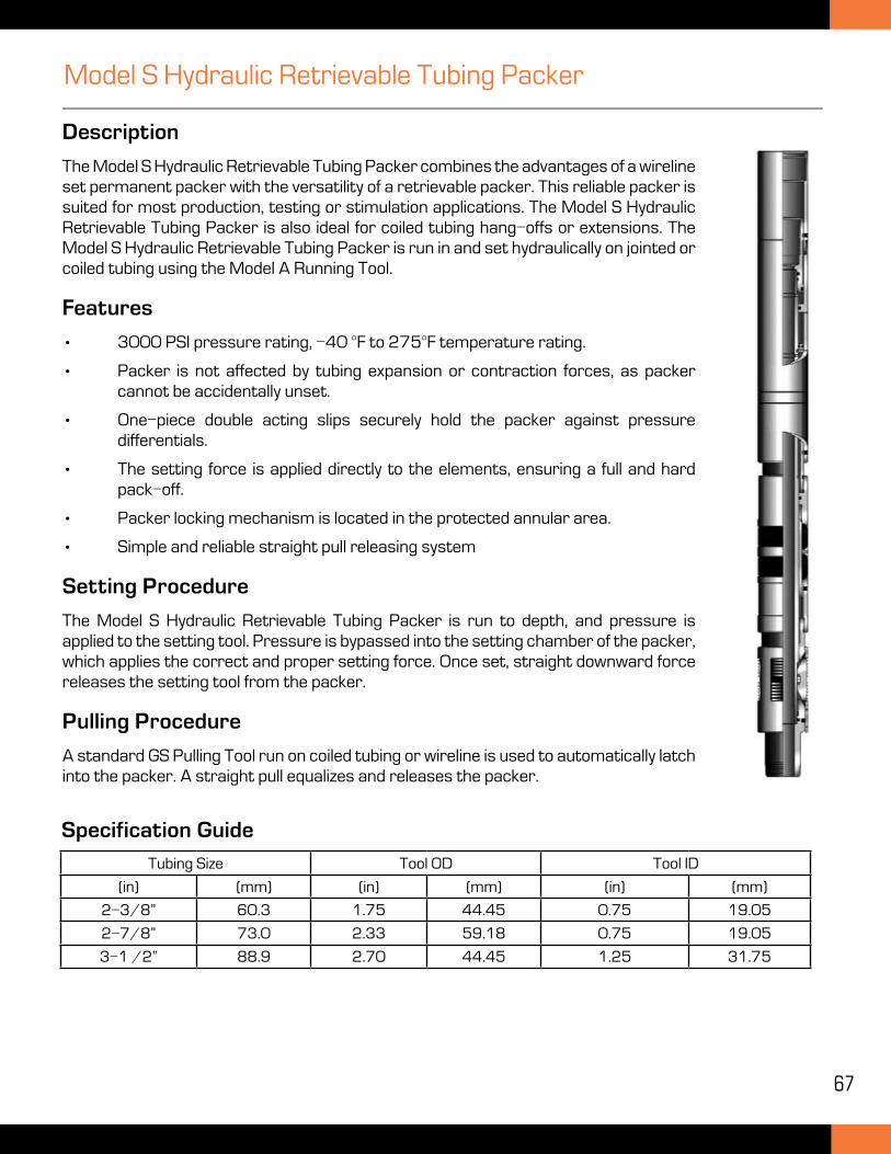
67
Model S Hydraulic Retrievable Tubing Packer
Description
The Model S Hydraulic Retrievable Tubing Packer combines the advantages of a wireline set permanent packer with the versatility of a retrievable packer. This reliable packer is suited for most production, testing or stimulation applications. The Model S Hydraulic Retrievable Tubing Packer is also ideal for coiled tubing hang-offs or extensions. The Model S Hydraulic Retrievable Tubing Packer is run in and set hydraulically on jointed or coiled tubing using the Model A Running Tool.
Features
• 3000 PSI pressure rating, -40 °F to 275°F temperature rating.
• Packer is not affected by tubing expansion or contraction forces, as packer cannot be accidentally unset.
• One-piece double acting slips securely hold the packer against pressure differentials.
• The setting force is applied directly to the elements, ensuring a full and hard pack-off.
• Packer locking mechanism is located in the protected annular area.
• Simple and reliable straight pull releasing system
Setting Procedure
The Model S Hydraulic Retrievable Tubing Packer is run to depth, and pressure is applied to the setting tool. Pressure is bypassed into the setting chamber of the packer, which applies the correct and proper setting force. Once set, straight downward force releases the setting tool from the packer.
Pulling Procedure
A standard GS Pulling Tool run on coiled tubing or wireline is used to automatically latch into the packer. A straight pull equalizes and releases the packer.
Tubing Size Tool OD Tool ID
(in) (mm) (in) (mm) (in) (mm)
2-3/8” 60.3 1.75 44.45 0.75 19.05
2-7/8” 73.0 2.33 59.18 0.75 19.05
3-1 /2” 88.9 2.70 44.45 1.25 31.75
Specification Guide

© 2015 TMK Completions. All rights reserved. Version 1.1