CONTROLLING THE SYNTHESIS OF PALLADIUM AND PLATINUM ...
153
CONTROLLING THE SYNTHESIS OF PALLADIUM AND PLATINUM NANOCRYSTALS FOR ELECTROCATALYTIC APPLICATIONS A Dissertation Presented to The Academic Faculty by Ruhui Chen In Partial Fulfillment of the Requirements for the Degree of Doctor of Philosophy in the School of Chemistry and Biochemistry Georgia Institute of Technology August 2021 COPYRIGHT © 2021 BY RUHUI CHEN
Transcript of CONTROLLING THE SYNTHESIS OF PALLADIUM AND PLATINUM ...

CONTROLLING THE SYNTHESIS OF PALLADIUM AND
PLATINUM NANOCRYSTALS FOR ELECTROCATALYTIC
APPLICATIONS
A Dissertation
Presented to
The Academic Faculty
by
Ruhui Chen
In Partial Fulfillment
of the Requirements for the Degree
of Doctor of Philosophy in the
School of Chemistry and Biochemistry
Georgia Institute of Technology
August 2021
COPYRIGHT © 2021 BY RUHUI CHEN

CONTROLLING THE SYNTHESIS OF PALLADIUM AND
PLATINUM NANOCRYSTALS FOR ELECTROCATALYTIC
APPLICATIONS
Approved by:
Dr. Younan Xia, Advisor
Department of Biomedical Engineering
Georgia Institute of Technology
Dr. Z. John Zhang
School of Chemistry and Biochemistry
Georgia Institute of Technology
Dr. Angus P. Wilkinson
School of Chemistry and Biochemistry
Georgia Institute of Technology
Dr. Zhiqun Lin
School of Materials Science and
Engineering
Georgia Institute of Technology
Dr. Ronghu Wu
School of Chemistry and Biochemistry
Georgia Institute of Technology
Date Approved: July 6, 2021

Dedicated to my parents who give me endless love and firm support for my every
adventure in life.

iv
ACKNOWLEDGEMENTS
First and foremost, I would like to express my deepest appreciation to my advisor,
Prof. Younan Xia, for his continuous support and guidance throughout my graduate study
at Georgia Tech. His insightful advice and constant encouragement carried me through all
the stages of completing this thesis. I would also like to extend my sincere thanks to my
committee members, Prof. Angus P. Wilkinson, Ronghu Wu, Z. John Zhang, and Zhiqun
Lin, who offered me invaluable suggestions for my research and shared the excitement of
my discovery.
The members of the Xia group and my collaborators have made my graduate study
productive and stimulating with their friendship, insights, and collaboration. I am
especially grateful to Dr. Miaofang Chi, Dr. Zhiheng Lyu, Dr. Ming Zhao, Dr. Zhenming
Cao, Dr. Zitao Chen, Minghao Xie, Yifeng Shi, and Quynh Nguyen, for their assistance in
the electron microscopy analysis, electrochemical measurements, as well as their valuable
comments towards my research; Dr. Jichuan Qiu, Dr. Yu Zhang, Dr. Da Huo for their
advice on academic life; Jianchang Xu, Fulin Yang, and Janssen Annemieke for their
generous help in the laboratory; Shi Shi, Peng Wang, and many others for the wonderful
time we spent together in the past few years.
Individually, I would like to give special thanks to my dearest friends who went
through hard time together, cheered me up, and celebrated each accomplishment: Yifan
Zhang, Yifeng Shi, and Yanjie Tong. Their consistent company and unwavering emotional
support helped me through every difficulty. My life was always brightened by the warmth
and laughter they brought to me.

v
In the end, I would like to express my deepest gratitude to my parents. Their firm
support and endless love encourage me to face every challenge in my life bravely and
confidently. They are my strength in everything I do.

vi
TABLE OF CONTENTS
ACKNOWLEDGEMENTS iv
LIST OF TABLES ix
LIST OF FIGURES x
LIST OF SYMBOLS AND ABBREVIATIONS xiv
SUMMARY xvi
CHAPTER
1. Introduction 1
1.1 Noble-Metal Nanocrystals: Properties, Applications, and the Importance of Shape
and Size Control 1
1.2 Nucleation and Growth: Critical Steps in Controlling the Product of a Colloidal
Synthesis 3
1.3 Challenges and Opportunities in Shape-Controlled Synthesis of Noble-Metal
Nanocrystals 8
1.3.1 Symmetry Reduction and Anisotropic Growth 8
1.3.2 Decoupling Growth from Nucleation 10
1.3.3 Scaling up the Production 13
1.4 Scope of This Work 15
1.5 Notes to Chapter 1 17
1.6 References 18
2. A Simple Route to the Synthesis of Platinum Nanobars and the Mechanistic
Understanding of Symmetry Reduction 22

vii
2.1 Introduction 22
2.2 Results and Discussion 24
2.3 Conclusion 40
2.4 Experimental Section 40
2.5 Notes to Chapter 2 41
2.6 References 42
3. Continuous and Scalable Synthesis of Platinum Multipods with Enhanced
Electrocatalytic Activity toward the Oxygen Reduction Reaction 45
3.1 Introduction 45
3.2 Results and Discussion 47
3.3 Conclusion 60
3.4 Experimental Section 61
3.5 Notes to Chapter 3 64
3.6 References 64
4. Improving the Purity and Uniformity of Palladium and Platinum Nanocrystals by
Decoupling Growth from Nucleation in a Flow Reactor 68
4.1 Introduction 68
4.2 Results and Discussion 72
4.3 Conclusion 96
4.4 Experimental Section 97
4.5 Notes to Chapter 4 100
4.6 References 100
5. Facile Synthesis of Platinum Right Bipyramids by Separating and Controlling the
viii
Nucleation Step in a Continuous Flow System 103
5.1 Introduction 103
5.2 Results and Discussion 106
5.3 Conclusion 121
5.4 Experimental Section 122
5.5 Notes to Chapter 5 124
5.6 References 124
6. Conclusions and Future Directions 127
6.1 Conclusions 127
6.2 Future Directions 130
6.3 Notes to Chapter 6 135
6.4 References 135

ix
LIST OF TABLES
Table 2.1 Experimental conditions for synthesizing Pt nanobars with
different sizes and aspect ratios.
29
Table 3.1 Comparison of the specific ECSAs, SAs, and MAs of the Pt
multipods/C and commercial Pt/C catalysts toward ORR.
57

x
LIST OF FIGURES
Figure 1.1 Importance of shape and size control of noble-metal nanocrystals
in catalytic applications.
2
Figure 1.2 Classical nucleation theory and the relationship between internal
structures of the seeds and initial reduction rate of the synthesis.
5
Figure 1.3 Shape evolution of a cubic nanocrystal under thermodynamic and
kinetic controls.
6
Figure 1.4 Symmetry breaking during nanocrystal growth. 9
Figure 1.5 Entanglement of nucleation and growth in a synthesis and two
different reduction pathways the precursor can take.
12
Figure 1.6 Scaling up the production of nanocrystals through the use of a
continuous flow reactor instead of an enlarged batch reactor.
14
Figure 2.1 TEM image and aspect ratio distribution of Pt nanobars. 25
Figure 2.2 TEM images of Pt nanocrystals prepared with different amounts
of Pt(IV) precursor introduced into the synthesis.
26
Figure 2.3 TEM images of Pt nanocrystals obtained with different amounts
of PVP involved in the synthesis.
28
Figure 2.4 FT-IR spectra of the Pt nanobars. 31
Figure 2.5 TEM images of Pt nanocrystals obtained using the standard
protocol except that DMF was replaced by benzyl alcohol and EG.
32
Figure 2.6 TEM images of intermediates obtained at different time points of
a standard synthesis.
33

xi
Figure 2.7 HRTEM images of Pt nanocrystals obtained at t=2.5 h into a
standard synthesis.
36
Figure 2.8 TEM images of Pt nanocrystals prepared following the standard
protocol except for different types of precursors and atmospheres.
37
Figure 2.9 The proposed growth pathways of Pt nanobars. 39
Figure 3.1 Scheme of the fluidic device used for a continuous flow synthesis
and TEM images of the Pt multipods.
48
Figure 3.2 HAADF-STEM image, HRTEM image and XRD pattern of the Pt
multipods.
50
Figure 3.3 TEM image of the Pt multipods synthesized in a glass vial. 51
Figure 3.4 TEM images showing the shape evolution of Pt multipods with
time.
53
Figure 3.5 TEM image of the carbon-supported Pt multipods. 55
Figure 3.6 Electrocatalytic properties of the Pt multipods/C toward ORR. 56
Figure 3.7 Calculation of the electron transfer number of ORR using the
Koutecky-Levich method.
58
Figure 3.8 Accelerated durability test of the Pt multipods/C catalyst. 59
Figure 3.9 Accelerated durability test of the commercial Pt/C catalyst. 60
Figure 4.1 Scheme of the fluidic device used to control the nucleation step
and TEM images of Pd nanocrystals obtained with/without
separating growth from nucleation.
73
Figure 4.2 TEM image of Pd nanocubes synthesized by following the
conventional protocol.
75

xii
Figure 4.3 The edge length and aspect ratio distribution of Pd nanocubes
synthesized by separating growth from nucleation and following
the conventional protocol.
76
Figure 4.4 TEM image of Pd nanocrystals obtained by using a glass vial to
trigger the nucleation.
78
Figure 4.5 TEM images of samples obtained at different time points of a
standard synthesis.
79
Figure 4.6 Quantitative analysis of the reduction kinetics using UV-vis
spectroscopy.
80
Figure 4.7 Calibration curve of PdBr42- solutions with different
concentrations for UV-vis analysis.
82
Figure 4.8 Scheme explaining the mechanism for different results obtained
with and without separating growth from nucleation.
84
Figure 4.9 TEM images of Pd nanocrystals prepared using the standard
protocol except for different durations for nucleation at 95 °C.
86
Figure 4.10 TEM image of Pd nanocrystals prepared with oxygen removed
from the reaction solution prior to the nucleation step.
88
Figure 4.11 TEM images of Pd nanocrystals obtained following the standard
protocol except for the variation in the temperature and duration
for nucleation.
90
Figure 4.12 TEM image of Pt seeds obtained using a polyol synthesis. 92

xiii
Figure 4.13 TEM image of Pt nanocubes obtained with/without separating
growth from nucleation and nanocrystals prepared using the
standard protocol except for the different temperatures for growth.
93
Figure 4.14 Size distributions of Pt nanocrystals obtained with/without
separating growth from nucleation.
95
Figure 5.1 Scheme of the experimental setup used for synthesizing Pt RBPs. 107
Figure 5.2 TEM and HAADF-STEM images of Pt RBPs. 108
Figure 5.3 TEM image of the product obtained by switching the atmosphere
in the growth stage from argon to air.
110
Figure 5.4 TEM image of the sample obtained by holding the reaction
solution containing 80% of the precursor used in a standard
synthesis at 120 ℃ for 48 h.
112
Figure 5.5 TEM images of the Pt seeds and product obtained using the
standard protocol except for using a vial to trigger the nucleation.
114
Figure 5.6 TEM images of Pt nanocrystals obtained at different stages of a
standard synthesis.
116
Figure 5.7 TEM images of Pt nanocrystals obtained using the standard
protocol except for the variation in the concentration of KBr.
118
Figure 5.8 TEM images of Pt nanocrystals prepared using the standard
protocol except for the different temperatures used for the
nucleation and growth stages.
120

xiv
LIST OF SYMBOLS AND ABBREVIATIONS
2-D two-dimensional
3-D three-dimensional
ATR attenuated total reflectance
CV cyclic voltammetry
DFT density functional theory
DMF N,N-dimethylformamide
ECSA electrochemically active surface area
EG ethylene glycol
FAO formic acid oxidation
fcc face-centered cubic
FTIR Fourier transform infrared
HAADF high-angle annular dark-field
HRTEM high-resolution transmission electron microscopy
ICP-MS inductively-coupled plasma mass spectrometry
IPA isopropyl alcohol
LSPR localized surface plasmon resonance
MA mass activity
OAm oleylamine
ORR oxygen reduction reaction
PEMFCs proton-exchange membrane fuel cells
PTFE polytetrafluoroethylene
PVP poly (vinyl pyrrolidone)

xv
RBPs right bipyramids
RDE rotating disk electrode
RHE reversible hydrogen electrode
SA specific activity
SAXS small angle X-ray scattering
SERS surface-enhanced Raman scattering
STEM scanning transmission electron microscopy
TEM transmission electron microscopy
UV-vis ultraviolet–visible
VRHE potential with refence to reversible hydrogen electrode
XAFS X-ray absorption fine structure
XRD X-ray diffraction

xvi
SUMMARY
Noble-metal nanocrystals with well-controlled attributes have found use in a variety
of applications, including those related to electrocatalysis and energy conversion. Since the
electrocatalytic performance of noble-metal nanocrystals critically depends on their sizes,
shapes, and internal structures, gaining deep insights into their nucleation and growth is
essential to achieving an ultimate control over their colloidal synthesis. In this dissertation,
I present a number of methods for controlling the synthesis of Pd and Pt nanocrystals to
improve their purity and uniformity in terms of size, shape, and structure, together with
evaluation of their electrocatalytic performance toward oxygen reduction. First, the
synthesis of Pt nanobars with aspect ratios tunable up to 2.1 was demonstrated by simply
heating a Pt(IV) precursor in N,N-dimethylformamide in the presence of poly(vinyl
pyrrolidone). A mechanistic study revealed that both particle coalescence and localized
oxidative etching followed by preferential growth contributed to the anisotropic growth
vital to the formation of nanobars. Recognizing the challenge in mass production of metal
nanocrystals without compromising the product quality, a continuous and scalable route to
Pt multipods was then developed by switching from a batch to a continuous flow reactor.
Investigation on the morphological evolution of Pt multipods indicated that the anisotropic
growth arose from a combination of fast autocatalytic surface reduction and attachment of
smaller particles. When supported on carbon, the Pt multipods exhibited enhanced activity
toward oxygen reduction relative to the commercial Pt/C catalyst. In addition to scaling up
the production volume, the tubular flow reactor was further demonstrated as a powerful
tool to tightly control the nucleation step of a synthesis. With Pd nanocrystals as an example,

xvii
the nucleation and growth could be decoupled from each other using a flow reactor to
trigger the nucleation, generating nanocubes highly uniform in both size and shape. Both
the temperature and duration for nucleation were found to significantly impact the seed
diversity and thus the quality of resultant nanocrystals. This methodology was also
successfully extended to the preparation of uniform, sub-5 nm Pt nanocubes. Utilizing this
strategy, Pt right bipyramids with a single twin plane and covered by {100} facets were
prepared in high quality. The Br- ions involved in the synthesis, as well as the pair of
temperatures used for the nucleation and growth steps, played critical roles in mediating
the formation of singly-twinned seeds and directing their evolution into right bipyramids.
The ability to control the nucleation and growth, coupled with in-depth mechanistic
understanding of these processes, will contribute to the rational synthesis of noble-metal
nanocrystals with desired features for electrocatalytic and other applications.

1
CHAPTER 1
INTRODUCTION
1.1 Noble-Metal Nanocrystals: Properties, Applications, and the Importance of
Shape and Size Control
Noble-metal nanocrystals with well-controlled attributes have received ever-
increasing attention in a variety of research fields, including electronics [1,2], photonics
[3,4], biomedicine [5,6], catalysis [7-9], and more. In paricular, owing to their outstanding
capability to donate and accept electrons for catalyzing both reduction and oxidation
reactions, catalysts based on noble-metal nanocrystals have been demonstrated
indipensible for numerous industrial processes [10], environmental protection [11], as well
as electrochemical reactions [12-14]. Notable examples include those based on Ru for the
Fischer-Tropsch Synthesis and ammonia production [15,16]; those based on Pd, Rh, and/or
Pt in catalytic converters [11]; those based on Pt for the operation of fuel cells [13]; and
those based on Cu for the electrochemical reduction of CO2 [12].
When catalyzing a reaction, the properties and performances of noble-metal
nanocrystals critically depend on their geometric shapes and internal structures
[7,14,17,18], in addition to their size [19,20]. Specifically, the activity and/or selectivity of
the noble-metal nanocrystals can be optimized by engineering the shape and thus
arrangement of atoms on the surface, as well as the electronic structures of the surface
atoms placed under strains [7]. For example, for formic acid oxidation (FAO) catalyzed by
Pd nanocrystals (Figure 1.1a), cubes enclosed by {100} facets exhibited a specific activity
two times higher than that of the tetrahedral counterparts covered by {111} facets, while

2
right bipyramids showed a further enhancement relative to cubes because of the presence
of twin boundaries [14]. In another example, Pt cuboctahedra with both {111} and {100}
facets exposed on the surface showed a specific activity twice that of cubes toward the
oxygen reduction reaction (ORR), whereas the concave cubes enclosed by high-index
facets displayed the highest activity among the catalysts (Figure 1.1b) [17]. To this end,
posing tight controls over the shape and internal structures of noble-metal nanocrystals is
particularly attractive in developing catalysts with enhanced performance for the target
reactions.
Figure 1.1. (a) Specific activities of Pd nanocrystals featuring different shapes and internal
structures toward FAO. (b) Specific activities of Pt nanocrystals enclosed by different
facets toward ORR. (c) Scheme showing sintering of two metal nanoparticles through
Ostwald ripening during a catalytic process. (a, b) Reprinted with permission from ref [14],
[17] and [21]. Copyrights 2012 Royal Society of Chemistry, 2011 Wiley-VCH and 2016
Annual Reviews, respectively. (c) Reprinted with permission from ref [22]. Copyright
2018 Royal Society of Chemistry.
In addition to geometric shape, close attention should also be paid to the size of
nanocrystals when considering their catalytic and electrocatalytic applications. It has been

3
well documented that the size of nanocrystals has significant impacts on their catalytic
activity and selectivity by affecting the specific surface area, the electronic structure of the
surface atoms and the fractions of atoms situated at vertices and edges [19,20]. In particular,
a narrow size distribution of the nanocrystals is highly demanded as polydispersity in size
could lead to degraded durability and performance in a catalytic process due to the sintering
of particles induced by Ostwald ripening (Figure 1.1c) [22,23]. Specifically, under the
harsh chemical or electrochemical environment, individual atoms or small clusters can
leave the surface of a smaller particle and be re-deposited onto the surface of a larger
particle [24]. In other words, small particles tend to dissolve and disappear, while
energetically-favorable large particles will keep growing, resulting in an increase in size
and thus a loss in specific surface area. As such, improving the uniformity of the
nanocrystals is supposed to be an effective means for mitigating Ostwald ripening and thus
enhancing the durability of the catalysts. Additionally, the well-defined facets on the
nanocrystals should also help strengthen their interactions with the support, making it
harder for the particles to migrate and coalesce, and therefore alleviating sintering and
degradation of their catalytic performance. Taken together, it is necessary to tightly control
the colloidal synthesis for the production of noble-metal nanocrystals with desired shapes
and internal structures while achieving size uniformity in order to develop effective
catalysts.
1.2 Nucleation and Growth: Critical Steps in Controlling the Product of a
Colloidal Synthesis
The significant success that has been achieved in engineering the size, shape, and
internal structure of noble-metal nanocrystals is built upon our mechanistic understanding

4
in nucleation and growth, the two critical steps involved in their colloidal synthesis.
Typically, homogeneous nucleation, which refers to the aggregation or assembly of metal
atoms into small clusters commonly known as nuclei, is regarded as the very first step of
any synthesis of nanocrystals without the introduction of preformed seeds. The general
framework of homogeneous nucleation can be described using the LaMer model, which
was formulated in the 1950s to account for the synthesis of sulfur colloids with a uniform
size distribution. This model can also be extended to the synthesis of noble-metal
nanocrystals (Figure 1.2a) [25]. As soon as the salt precursor is reduced or decomposed,
the concentration of metal atoms in the reaction solution is expected to increase as a
function of time. Once the concentration of metal atoms exceeds the minimum value for
nucleation (𝐶𝑚𝑖𝑛𝑛𝑢 ), homogeneous nucleation (or self-nucleation) will occur to generate
nuclei. Rapid consumption of the atoms in the solution will cause their concentration to
decrease quickly and homogeneous nucleation will cease when the concentration drops
below the minimum level for nucleation. Afterwards, the nuclei evolve into seeds with
specific internal structures, followed by growth to nanocrystals taking different shapes.
It has been well established that the final shape taken by the nanocrystals is closely
related to the internal structures of seeds formed in the initial synthesis [27,28]. As such,
to obtain nanocrystals with desired attributes, it is critical to manipulate the fractions of
different types of seeds generated during nucleation, which relies on both thermodynamic
and kinetic aspects of the synthesis. In a previous study, it was indicated that multiply-
twinned and single-crystal seeds were formed at relatively small and large sizes,
respectively [29]. Alternatively, the initial reduction rate of the precursor has been
demonstrated as a quantitative knob for experimentally controlling the internal structure of

5
the seeds [26]. As shown in Figure 1.2b, with the initial reduction rate decreasing, the seeds
generated during nucleation would switch from single-crystal to multiply-twinned and
finally stacking-fault-lined structure. The well-separated windows of initial reduction rates
correlate well with the formation of seeds with different internal structures. In practice, the
initial reduction rate can be experimentally controlled by adjusting the reaction temperature,
the type of precursor and reductant involved in the synthesis, as well as their concentrations
[26,30-32].
Figure 1.2. (a) Plot of the concentration of atoms as a function of reaction time, illustrating
the major steps involved in a colloidal synthesis, including the generation of atoms,
homogeneous nucleation, and growth. (b) Plot showing the relative distribution of Pd
nanocrystals taking different internal structures as a function of the initial reduction rate of
a polyol synthesis. The formation of plates with stacking faults, multiply twinned
icosahedra, and single-crystal cuboctahedra are denoted in green, black and blue lines,
respectively.(a) Reprinted with permission from ref [25]. Copyright 1950 American
Chemical Society. (b) Reprinted with permission from ref [26]. Copyright 2015 American
Chemical Society.
After the nucleation of seeds featuring specific internal structures, growth is then
responsible for faceting or shape development, and size enlargement of the nanocrystals.

6
Specifically, the newly-formed atoms are supposed to be deposited on the surface of the
preformed seeds to enable growth. During this process, the internal structure of the seeds
is more or less kept, while the ultimate shape taken by the product is determined by the
interplay among multiple thermodynamic and kinetic factors defined by the experimental
conditions [33]. In essence, the thermodynamically-controlled product should exhibit a
global minimum in terms of total energy, including the contributions from surface, volume,
defects, and strains [34]. In comparison, many nanocrystals would settle into structures at
locally stable positions instead of reaching the global minimum in free energy, known as
kinetically-controlled products.
Figure 1.3. Schematic illustration of the shape evolution of a cubic seed under different
conditions during the growth stage. The two-dimensional (2-D) atomic models correspond
to the cross-section of the three-dimensional (3-D) model as marked by the red dashed line.
Reprinted with permission from ref [33]. Copyright 2015 American Chemical Society.

7
According to the Arrhenius equation (reaction rate constant = 𝐴𝑒−𝐸𝑎𝑅𝑇 ), the most
effective way to promote a thermodynamically-controlled synthesis is to raise the reaction
temperature for overcoming the energy barriers more easily. In contrast, a relatively low
temperature is more desired for a kinetically-controlled synthesis because it allows one to
finely tune the kinetic parameters, including the atom deposition and surface diffusion rates
(denoted as Vdep and Vdiff, respectively), to access and stay at local minima in terms of total
free energy [35].
In principle, whether the product is formed under thermodynamic or kinetic control is
determined by the surface diffusion rate. An exemplary illustration can be found in the
growth of a cubic seed (Figure 1.3), in which the surface energies of various sites on the
cube increase in the order of side faces, corners, and edges owing to the difference in
coordination number for the atoms and presence of a capping agent on the side faces.
During deposition, atoms under thermodynamic control involve a much greater Vdiff
relative to Vdep and their behavior follows a “hit-then-diffuse” fashion across the surface of
a seed, giving rise to thermodynamically-favored nanocrystals featuring the Wulff shape.
In contrast, atoms under kinetic control will follow site-selected growth, producing diverse
products including concave cubes and octapods as the ratio of Vdiff and Vdep is decreased
[35]. To manipulate the relative rate of atom deposition to surface diffusion and thus the
shape evolution of nanocrystals, effective means include the variation in reaction
temperature, the change in the activity and concentration of the metal precursor and
reductant, the addition of a capping agent for passivating a specific type of facet, the
inclusion of oxidative etching or galvanic replacement, among others [35-38].

8
1.3 Challenges and Opportunities in Shape-Controlled Synthesis of Noble-Metal
Nanocrystals
1.3.1 Symmetry Reduction and Anisotropic Growth
During a colloidal synthesis of noble-metal nanocrystals, the seeds obtained after
nucleation will further grow into nanocrystals with larger sizes and different shapes
through either atomic addition or particle attachment [27,28,39], depending on the
experimental conditions involved. Specifically, for the deposition of the newly-formed
atoms on the growing nanocrystals, it can take a symmetric or asymmetric pattern to
preserve or break the symmetry of the seeds, generating products with distinct shapes
(Figure 1.4a) [40]. The nanocrystals derived through symmetry breaking could exhibit
intriguing optical and catalytic properties, as well as enhanced performance in the related
applications. Notable examples include nanowires with outstanding activity and durability
for electrocatalysis [41,42], nanorods with tunable localized surface plasmon resonance
(LSPR) for photothermal treatment [43], and dumbbell-shaped nanostructures for
biomedical imaging [44], among others. Therefore, symmetry breaking has received much
research interest in understanding the fundamentals of nanocrystal growth while offering
an additional handle for engineering the shape of metal nanocrystals and thus enhancing
their performance in various applications.
Owing to the constraint from the high symmetry of crystal lattice, it is challenging to
induce anisotropic growth in noble-metal nanocrystals as they tend to grow into shapes
retaining the symmetry of the lattice. For example, for a cuboctahedral seed made of a face-
centered cubic (fcc) metal, it possesses multiple equivalent facets where the surface atoms
have the same spatial arrangement and coordination number. Thus, there is no intrinsic
9
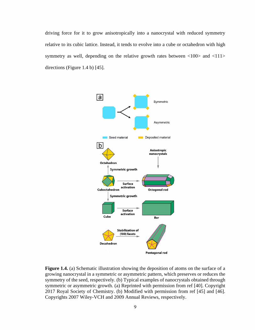
driving force for it to grow anisotropically into a nanocrystal with reduced symmetry
relative to its cubic lattice. Instead, it tends to evolve into a cube or octahedron with high
symmetry as well, depending on the relative growth rates between <100> and <111>
directions (Figure 1.4 b) [45].
Figure 1.4. (a) Schematic illustration showing the deposition of atoms on the surface of a
growing nanocrystal in a symmetric or asymmetric pattern, which preserves or reduces the
symmetry of the seed, respectively. (b) Typical examples of nanocrystals obtained through
symmetric or asymmetric growth. (a) Reprinted with permission from ref [40]. Copyright
2017 Royal Society of Chemistry. (b) Modified with permission from ref [45] and [46].
Copyrights 2007 Wiley-VCH and 2009 Annual Reviews, respectively.

10
To this end, several strategies have been proposed to break the cubic symmetry defined
by the lattice of an fcc metal, including limiting the supply of atoms [47], involvement of
oxidative etching [48], incorporation of defects into the structures [49], and aggregation or
attachment of the particles [50], among others [40]. For example, as shown in Figure 1.4b,
by selectively activating one side faces of a cuboctahedron (or cube) through localized
oxidative etching, anisotropic growth can take place from that face, giving rise to single-
crystal nanorod and nanobar as the products, respectively [36]. In another example, with
the {100} facets stabilized by a capping agent, a decahedron can uniaxially grow into a
penta-twinned nanorod or nanowire instead of growing along the lateral dimensions due to
the possible increase in strain energy associated with the twin defects [51]. Although
progress has been made in the synthesis of noble-metal nanocrystals with lower symmetry
relative to their cubic lattice, the methods available are still limited and the mechanistic
understanding of anisotropic growth still needs further advancement. To promote the
potential applications of nanocrystals with reduced symmetry, it is vital to expand our
synthetic capability to induce symmetry reduction and anisotropic growth in a well-
controlled manner.
1.3.2 Decoupling Growth from Nucleation
Despite the significant progress in colloidal synthesis of noble-metal nanocrystals
with desired attributes, the product quality is usually plagued by polydispersity in terms of
both the size and shape, resulting in degradation of their catalytic performance. The
polydispersity can be ascribed to the occurrence of multiple nucleation events in a synthesis.
Based on the LaMer model, which offers an insightful instruction about how to obtain
nanocrystals with good uniformity, it is necessary to ensure that the nucleation and growth

11
processes are decoupled from each other and there is only one nucleation event per
synthesis. Otherwise, products with different shapes and a broad size distribution would be
generated as various types of seeds are formed during different cycles of nucleation and
they would experience different durations of growth (Figure 1.5a). In a conventional
synthesis, with the continuous supply of metal atoms from the precursor, the concentration
of atoms can still surpass the threshold for nucleation even after entering the “growth”
stage. In this case, homogeneous nucleation can be enabled multiple times in a synthesis,
until most of the precursor in the solution has been depleted, leading to polydispersity of
the resultant nanocrystals. As such, decoupling nucleation and growth stages is critical in
obtaining nanocrystals uniform in size and shape.
In a synthesis, the reduction of precursor can take two different pathways (Figure
1.5b): solution reduction and surface reduction [52], which can be leveraged to decouple
growth from nucleation. For the solution pathway, the precursor compound is directly
reduced in the solution phase through collision and electron transfer with the reductant
molecule, and the atoms are then deposited on the surface of a seed to facilitate its growth.
The atoms can also aggregate to generate new nuclei. In contrast, surface reduction relies
on the assistance from the existing seed to facilitate the production of metal atoms: the
precursor will adsorb onto the surface of a seed, followed by its reduction to an atom
through an autocatalytic mechanism [53,54]. The activation energies for these two different
reduction pathways differ significantly, with a lower activation energy barrier to surface
reduction due to the presence of seeds acting as a “catalyst” for the reduction process.

12
Figure 1.5. (a) Scheme based on the LaMer model showing the entanglement of nucleation
and growth in a synthesis, where multiple nucleation events can take place during growth,
resulting in polydispersity of the product. (b) Two different reduction pathways that the
precursor can take during a colloidal synthesis of metal nanocrystals: solution and surface
reduction, respectively. (a) Reprinted with permission from ref [55]. Copyright 2007
Elsevier. (b) Reprinted with permission from ref [52]. Copyright 2017 American Chemical
Society.
In general, homogeneous nucleation only involves solution reduction while both
surface and solution reduction can participate in the growth process. To decouple growth
from nucleation, the precursor should take the solution reduction pathway during the
nucleation stage to generate seeds while switching to surface reduction during growth. If
solution reduction is still allowed in the growth stage, the product may contain a second

13
population of nanocrystals, typically with a much smaller size, due to the involvement of
additional homogenous nucleation events rather than just growth [55]. The reduction
kinetics has a strong correlation with the reduction pathway taken by the salt precursor,
with the fast and slow ones favoring solution and surface reduction, respectively. There
exists a transition point in the reduction rate for separating the two distinctive pathways
[52]. Below the critical rate, surface reduction will take over the dominance in the
generation of atoms whereas solution reduction will exert a major effect when the reduction
rate is above the critical level. By finely tuning the reduction kinetics, it is feasible to
manipulate the reduction pathway of the precursor and thereby decouple growth from
nucleation in a synthesis to improve the purity and uniformity of the obtained nanocrystals.
1.3.3 Scaling up the Production
Although noble-metal nanocrystals with well-defined shapes and internal structures
have found use in various catalytic applications, it remains a grand challenge to scale up
their production without compromising the product quality. So far, the protocols reported
in literature are mainly based on the use of small batch reactors, with throughputs far below
the demands from industrial applications. For example, it takes almost three hours to just
produce 0.02 g of Pd nanocubes in a typical glass vial without considering complicated
post treatments [56], whereas a typical three-way catalytic converter for a compact
passenger vehicle requires 1−2 g of the Pd catalyst [11]. Therefore, it is of great importance
to bridge the gap between lab-scale production and commercial demand by scaling up the
synthesis. To this end, it seems straightforward to simply conduct the synthesis in an
enlarged reactor by slightly modifying the experimental protocol (Figure 1.6).
Unfortunately, since the nucleation process is extremely sensitive to the experimental

14
parameters, the product quality would be significantly marred by the thermal and
compositional inhomogeneity arising from a large reaction volume [57]. The uncertainty
about the product quality may also result in the production of a large amount of waste,
which is economically and environmentally unfavorable.
Figure 1.6. Schematic illustration showing the utilization of a continuous flow reactor to
linearly scale up the production of noble-metal nanocrystals, instead of increasing the
volume of the reaction solution in a larger batch reactor. Modified with permission from
ref [57] and [58]. Copyright 2014 Wiley-VCH and 2015 Elsevier, respectively.
Instead of increasing the volume of the reaction solution and the size of the reactor,
one can achieve mass production without compromising the product quality by conducting
the synthesis in a continuous flow reactor [58]. As shown in Figure 1.6, the solution can be
introduced into a channel with one segment subjected to an external stimulus for triggering
the reaction, such as heating, ultrasonication, and irradiation, among others. As such, the
throughput can be readily increased by running the synthesis continuously because of the
linear correlation between the volume of production and the duration of the synthesis.
Benefiting from the fast rates of heat and mass transfer enabled by the small lateral

15
dimensions of the flow reactor, the nucleation and growth of nanocrystals can be kept
essentially the same as in a conventional batch reactor, ensuring a tight control over the
size and shape of the products. Therefore, it is of great importance to develop synthetic
protocols that are suitable for conducting the synthesis in continuous flow reactors, in an
effort to scale up the production of noble-metal nanocrystals without compromising their
quality and push them closer to practical use.
1.4 Scope of This Work
The aim of this dissertation is to introduce various strategies for controlling the
synthesis of Pd and Pt nanocrystals with well-defined shapes and structures, improved
purity and uniformity, as well as evaluation of their performance in electrocatalytic
applications. Facile routes were developed for the preparation of Pt nanocrystals with
reduced symmetry relative to their cubic lattice and then incorporated with continuous flow
reactor to scale up the production, in addition to evaluating their catalytic performance
toward ORR. By characterizing the products and the reaction intermediates, the
mechanisms responsible for the anisotropic growth were elucidated. The continuous flow
system was then utilized to control the nucleation step of a colloidal synthesis and decouple
growth from nucleation, in an effort to improve the purity and uniformity of the
nanocrystals.
In CHAPTER 2, I develop a facile method for the preparation of Pt nanobars with
aspect ratios tunable up to 2.1 and uncover the mechanism responsible for anisotropic
growth. The synthesis simply involves heating a Pt(IV) precursor in N,N-
dimethylformamide (DMF) at 160 °C in the presence of poly (vinyl pyrrolidone) (PVP).
In addition to its commonly observed roles as a solvent and a reductant, DMF can also

16
decompose to generate CO, a capping agent capable of selectively passivating Pt{100}
facets to promote the formation of nanobars. The size and aspect ratio of the nanobars can
be tuned by varying the amount of Pt(IV) precursor involved in the synthesis, as well as
the concentration of PVP because of its dual roles as a stabilizer and a co-reductant. The
mechanistic study indicates that the anisotropic growth results from both particle
coalescence and localized oxidative etching followed by preferential growth.
In CHAPTER 3, I demonstrate the use of a fluidic device for the continuous and
scalable synthesis of Pt multipods with small sizes and enhanced catalytic activity toward
ORR. The facile protocol involves the use of Pt(acac)2 as a precursor to Pt and oleylamine
as a solvent, surfactant, and temperature-dependent reductant. When a solution of these
two components is pumped into the polytetrafluoroethylene tube immersed in an oil bath
and held at 180 °C, Pt multipods are formed through fast autocatalytic surface growth and
small particles attachment. Compared with the batch-based synthesis, the throughput of the
production in the flow system can readily be increased to 17 mg of Pt per hour while
retaining a tight control over the quality of the products. When supported on carbon, the Pt
multipods exhibit enhanced activity toward oxygen reduction relative to the commercial
Pt/C catalyst.
In CHAPTER 4, I demonstrate that nucleation and growth can be decoupled from
each other to improve the purity and uniformity of metal nanocrystals by re-designing the
experimental setup while manipulating the reduction pathway of the precursor. Specifically,
taking Pd nanocrystals as an example, I pump the reaction solution through a tubular flow
reactor and trigger a single burst of nucleation by subjecting the solution to an elevated
temperature for a very short period of time to enable solution-phase reduction. The solution

17
is then kept at room temperature for slow growth through surface reduction, producing pure
and uniform Pd nanocubes. Due to the elimination of additional nucleation events during
growth, the products exhibit high uniformity in terms of both size and shape. I elucidate
the mechanistic details by quantitatively analyzing the reduction kinetics and monitoring
the nanocrystals obtained at different stages of a synthesis. I further investigate the impacts
of both temperature and duration of nucleation on the diversity of seeds and the quality of
resultant nanocrystals. This methodology has also been extended to the preparation of sub-
5 nm Pt nanocubes and is potentially applicable to the synthesis of other types of colloidal
nanocrystals.
In CHAPTER 5, I extend the strategy of separating nucleation from growth and
controlling the nucleation step in a continuous flow system to the synthesis of Pt right
bipyramids (RBPs) with a singly-twinned structure. Specifically, homogeneous nucleation
is thermally triggered by introducing the reaction solution into a tubular flow reactor held
at an elevated temperature to generate singly-twinned seeds. At a lower temperature, the
singly-twinned seeds are protected from oxidative etching to allow their slow growth and
evolution into RBPs while additional nucleation of undesired seeds can be largely
suppressed to ensure RBPs as the main product. Further investigation indicates that the
internal structure and growth pattern of the seeds are determined by the temperatures used
for the nucleation and growth steps, respectively. The Br- ions involved in the synthesis
also play a critical role in the generation of RBPs by serving as a capping agent for the
Pt{100} facets while regulating the reduction kinetics through coordination with the Pt(Ⅳ)
ions.
1.5 Notes to Chapter 1
18
Part of this Chapter is adapted from the articles “A Simple Route to the Synthesis of
Pt Nanobars and the Mechanistic Understanding of Symmetry Reduction” published in
Chemistry-A European Journal [59], “Continuous and Scalable Synthesis of Pt Multipods
with Enhanced Electrocatalytic Activity toward the Oxygen Reduction Reaction”
published in ChemNanoMat [60], “Improving the Purity and Uniformity of Pd and Pt
Nanocrystals by Decoupling Growth from Nucleation in a Flow Reactor” published in
Chemistry of Materials [61], “Facile Synthesis of Platinum Right Bipyramids by
Separating and Controlling the Nucleation Step in a Continuous Flow System” submitted
to Chemistry-A European Journal, and “Noble-Metal Nanocrystals with Controlled Shapes
for Catalytic and Electrocatalytic Applications” co-authored by me and published in
Chemical Reviews [7].
1.6 References
[1] Kim, K. K.; Hong, S.; Cho, H. M.; Lee, J.; Suh, Y. D.; Ham, J.; Ko, S. H. Nano
Lett. 2015, 15, 5240−5247.
[2] Guo, C. F.; Ren, Z. Mater. Today 2015, 18, 143−154.
[3] Fang, Y.; Li, Z.; Huang, Y.; Zhang, S.; Nordlander, P.; Halas, N. J.; Xu, H. Nano
Lett. 2010, 10, 1950−1954.
[4] Guo, X.; Qiu, M.; Bao, J.; Wiley, B. J.; Yang, Q.; Zhang, X.; Ma, Y.; Yu, H.; Tong,
L. Nano Lett. 2009, 9, 4515−4519.
[5] Yang, X.; Yang, M.; Pang, B.; Vara, M.; Xia, Y. Chem. Rev. 2015, 115,
10410−10488.
[6] Tran, T.-H.; Nguyen, T.-D. Colloids Surf. B. 2011, 88, 1−22.
[7] Shi, Y.; Lyu, Z.; Zhao, M.; Chen, R.; Nguyen, Q. N.; Xia, Y. Chem. Rev. 2021, 121,
649−735.
[8] Wu, B.; Zheng, N. Nano Today 2013, 8, 168−197.
[9] Fan, Z.; Zhang, H. Acc. Chem. Res. 2016, 49, 2841−2850.

19
[10] Liu, L.; Corma, A. Chem. Rev. 2018, 118, 4981−5079.
[11] Tollefson, J. Nature 2007, 450, 334−335.
[12] Nitopi, S.; Bertheussen, E.; Scott, S. B.; Liu, X.; Engstfeld, A. K.; Horch, S.; Seger,
B.; Stephens, I. E. L.; Chan, K.; Hahn, C.; Nørskov, J. K.; Jaramillo, T. F.;
Chorkendorff, I. Chem. Rev. 2019, 119, 7610−7672.
[13] Zhao, Z.; Chen, C.; Liu, Z.; Huang, J.; Wu, M.; Liu, H.; Li, Y.; Huang, Y. Adv.
Mater. 2019, 31, 1808115.
[14] Jin, M.; Zhang, H.; Xie, Z.; Xia, Y. Energy Environ. Sci. 2012, 5, 6352−6357.
[15] Liu, J.-X.; Wang, P.; Xu, W.; Hensen, E. J. M. Engineering 2017, 3, 467−476.
[16] Saadatjou, N.; Jafari, A.; Sahebdelfar, S. Chem. Eng. Commun. 2015, 202, 420−448.
[17] Yu, T.; Kim, D. Y.; Zhang, H.; Xia, Y. Angew. Chem. Int. Ed. 2011, 50, 2773−2777.
[18] Zhang, J.; Kuang, Q.; Jiang, Y.; Xie, Z. Nano Today 2016, 11, 661−677.
[19] Xie, S.; Choi, S.-I.; Xia, X.; Xia, Y. Curr. Opin. Chem. Eng. 2013, 2, 142−150.
[20] Cao, S.; Tao, F.; Tang, Y.; Li, Y.; Yu, J. Chem. Soc. Rev. 2016, 45, 4747−4765.
[21] Ruditskiy, A.; Peng, H. C.; Xia, Y. Annu. Rev. Chem. Biomol. Eng. 2016, 7,
327−348.
[22] Dai, Y.; Lu, P.; Cao, Z.; Campbell, C. T.; Xia, Y. Chem. Soc. Rev. 2018, 47,
4314−4331.
[23] Goodman, E. D.; Carlson, E. Z.; Dietze, E. M.; Tahsini, N.; Johnson, A.; Aitbekova,
A.; Nguyen Taylor, T.; Plessow, P. N.; Cargnello, M. Nanoscale 2021, 13, 930−938.
[24] Voorhees, P. W. J. Stat. Phys. 1985, 38, 231−252.
[25] LaMer, V. K.; Dinegar, R. H. J. Am. Chem. Soc. 1950, 72, 4847−4854.
[26] Wang, Y.; Peng, H.-C.; Liu, J.; Huang, C. Z.; Xia, Y. Nano Lett. 2015, 15,
1445−1450.
[27] Xia, Y.; Xiong, Y.; Lim, B.; Skrabalak, S. E. Angew. Chem. Int. Ed. 2009, 48,
60−103.
[28] Xia, Y.; Gilroy, K. D.; Peng, H.-C.; Xia, X. Angew. Chem. Int. Ed. 2017, 56, 60−95.
[29] Barnard, A. S.; Young, N. P.; Kirkland, A. I.; van Huis, M. A.; Xu, H. ACS Nano
2009, 3, 1431−1436.

20
[30] Biacchi, A. J.; Schaak, R. E. ACS Nano 2011, 5, 8089−8099.
[31] Woehl, T. J.; Evans, J. E.; Arslan, I.; Ristenpart, W. D.; Browning, N. D. ACS Nano
2012, 6, 8599−8610.
[32] Zhou, M.; Wang, H.; Vara, M.; Hood, Z. D.; Luo, M.; Yang, T.-H.; Bao, S.; Chi,
M.; Xiao, P.; Zhang, Y.; Xia, Y. J. Am. Chem. Soc. 2016, 138, 12263−12270.
[33] Xia, Y.; Xia, X.; Peng, H.-C. J. Am. Chem. Soc. 2015, 137, 7947−7966.
[34] Wang, Y.; He, J.; Liu, C.; Chong, W. H.; Chen, H. Angew. Chem. Int. Ed. 2015, 54,
2022-2051.
[35] Xia, X.; Xie, S.; Liu, M.; Peng, H.-C.; Lu, N.; Wang, J.; Kim, M. J.; Xia, Y. Proc.
Natl. Acad. Sci. U. S. A. 2013, 110, 6669.
[36] Xiong, Y.; Cai, H.; Wiley, B. J.; Wang, J.; Kim, M. J.; Xia, Y. J. Am. Chem. Soc.
2007, 129, 3665−3675.
[37] Xie, S.; Lu, N.; Xie, Z.; Wang, J.; Kim, M. J.; Xia, Y. Angew. Chem. Int. Ed. 2012,
51, 10266−10270.
[38] Yang, T.-H.; Shi, Y.; Janssen, A.; Xia, Y. Angew. Chem. Int. Ed. 2020, 59,
15378−15401.
[39] Lv, W.; He, W.; Wang, X.; Niu, Y.; Cao, H.; Dickerson, J. H.; Wang, Z. Nanoscale
2014, 6, 2531−2547.
[40] Gilroy, K. D.; Peng, H.-C.; Yang, X.; Ruditskiy, A.; Xia, Y. Chem. Commun. 2017,
53, 4530−4541.
[41] Koenigsmann, C.; Santulli, A. C.; Gong, K.; Vukmirovic, M. B.; Zhou, W.-p.;
Sutter, E.; Wong, S. S.; Adzic, R. R. J. Am. Chem. Soc. 2011, 133, 9783−9795.
[42] Huang, H.; Ruditskiy, A.; Choi, S.-I.; Zhang, L.; Liu, J.; Ye, Z.; Xia, Y. ACS Appl.
Mater. Interfaces 2017, 9, 31203−31212.
[43] Chen, H.; Shao, L.; Li, Q.; Wang, J. Chem. Soc. Rev. 2013, 42, 2679−2724.
[44] Xu, C.; Xie, J.; Ho, D.; Wang, C.; Kohler, N.; Walsh, E. G.; Morgan, J. R.; Chin,
Y. E.; Sun, S. Angew. Chem. Int. Ed. 2008, 47, 173−176.
[45] Xiong, Y.; Xia, Y. Adv. Mater. 2007, 19, 3385−3391.
[46] Lu, X.; Rycenga, M.; Skrabalak, S. E.; Wiley, B.; Xia, Y. Annu. Rev. Phys. Chem.
2009, 60, 167−192.
[47] Xia, X.; Xia, Y. Nano Lett. 2012, 12, 6038−6042.
21
[48] Cobley, C. M.; Rycenga, M.; Zhou, F.; Li, Z.-Y.; Xia, Y. Angew. Chem. Int. Ed.
2009, 48, 4824−4827.
[49] Langille, M. R.; Zhang, J.; Personick, M. L.; Li, S.; Mirkin, C. A. Science 2012,
337, 954.
[50] Halder, A.; Ravishankar, N. Adv. Mater. 2007, 19, 1854−1858.
[51] Wiley, B.; Sun, Y.; Xia, Y. Acc. Chem. Res. 2007, 40, 1067−1076.
[52] Yang, T.-H.; Peng, H.-C.; Zhou, S.; Lee, C.-T.; Bao, S.; Lee, Y.-H.; Wu, J.-M.; Xia,
Y. Nano Lett. 2017, 17, 334−340.
[53] Yang, T.-H.; Zhou, S.; Gilroy, K. D.; Figueroa-Cosme, L.; Lee, Y.-H.; Wu, J.-M.;
Xia, Y. Proc. Natl. Acad. Sci. U. S. A. 2017, 114, 13619.
[54] Watzky, M. A.; Finke, R. G. J. Am. Chem. Soc. 1997, 119, 10382−10400.
[55] Park, B. K.; Jeong, S.; Kim, D.; Moon, J.; Lim, S.; Kim, J. S. J. Colloid Interface
Sci. 2007, 311, 417−424.
[56] Jin, M.; Liu, H.; Zhang, H.; Xie, Z.; Liu, J.; Xia, Y. Nano Res. 2010, 4, 83−91.
[57] Zhang, L.; Xia, Y. Adv. Mater. 2014, 26, 2600−2606.
[58] Batten, M. P.; Rubio-Martinez, M.; Hadley, T.; Carey, K.-C.; Lim, K.-S.; Polyzos,
A.; Hill, M. R. Curr. Opin. Chem. Eng. 2015, 8, 55−59.
[59] Chen, R.; Nguyen, Q. N.; Zhao, M.; Chen, Z.; Chi, M.; Xia, Y. Chem. Eur. J. 2021,
27, 2760−2766.
[60] Chen, R.; Cao, Z.; Lyu, Z.; Xie, M.; Shi, Y.; Xia, Y. ChemNanoMat 2019, 5,
599−605.
[61] Chen, R.; Lyu, Z.; Shi, Y.; Xia, Y. Chem. Mater. 2021, 33, 3791−3801.

22
CHAPTER 2
A SIMPLE ROUTE TO THE SYNTHESIS OF PLATINUM
NANOBARS AND THE MECHANISTIC UNDERSTANDING OF
SYMMETRY REDUCTION
2.1 Introduction
The successful synthesis of noble-metal nanocrystals with diverse shapes offers
exciting opportunities in a wide variety of applications [1-4]. Even if enclosed by the same
crystallographic facets, nanocrystals taking different geometric shapes could still exhibit
different properties and performances [1,5]. A notable example can be found in the surface-
enhanced Raman scattering (SERS) property of Ag nanobars, which is highly dependent
on their aspect ratio [6]. A nanobar is enclosed by six {100} side faces similar to a nanocube,
but elongated along one (or two) direction with an aspect ratio greater than one. Besides
the unique features in plasmonics, nanobars might also exhibit attractive catalytic
properties. Although the type of facet or surface structure of nanocubes and nanobars is
essentially identical, their difference in specific surface area and the proportion of
undercoordinated atoms situated on edges and corners can lead to distinct catalytic
performance [1]. For example, the Pt nanobar exhibited different CO poisoning tolerance
in methanol oxidation reaction as its aspect ratio varied, but the mechanism is yet to be
resolved [7]. Moreover, by enlarging the area in contact with the support, it is expected that
the movement and detachment of nanobars will be mitigated under the harsh
electrochemical conditions, enabling higher durability, as reported for catalysts based on
one-dimensional metal nanocrystals [8-10].

23
Despite the attractive properties of nanobars, it is challenging to induce anisotropic
growth during a colloidal synthesis of noble-metal nanocrystals, owing to the constraint
from their fcc lattice [11,12]. Enclosed by multiple equivalent facets possessing surface
atoms with the same spatial arrangement and coordination number, there is no intrinsic
driving force for an fcc metal to break its cubic symmetry and grow into an anisotropic
shape. To this end, a variety of strategies have been proposed and demonstrated for
generating nanobars, including particle attachment [7,13], facet-selected growth as a result
of localized oxidative etching [6,14], and manipulation of reduction kinetics [15]. Although
progress has been made in the synthesis of nanobars, the available synthetic methods and
understanding of the mechanism responsible for anisotropic growth and symmetry
reduction is still limited, compared with other types of one-dimensional nanostructures, let
alone nanocrystals taking isotropic shapes. To promote the potential applications of
nanobars, it is of critical importance to deepen our understanding in symmetry reduction
for achieving anisotropic growth in a controllable manner.
Most of the synthetic protocols that have been developed so far focus on the
preparation of Pd [13,14,16,17], Ag [6,15,18,19], and bimetallic [20,21] nanobars. As for
Pt, although it has been demonstrated as a key catalytic material for a number of reactions
and industrial processes [1], limited success has been achieved in the synthesis of Pt
nanobars with well-defined facets and controlled aspect ratio [7,14]. Due to the difference
in intrinsic properties among various metals, the synthetic method for Pt nanobars tends to
differ from those developed for other metals and thus need further study. In an early report,
it was demonstrated that Pt nanobars could be prepared by reducing Na2PtCl6 in a mixture
of ethylene glycol (EG) and water in the presence of KBr and PVP [14]. The localized

24
oxidative etching enabled by the Cl-/O2 pair selectively removed Br- ions from one of the
side faces on a cube to activate the preferential growth for the generation of nanobars.
However, the product quality was poor. In another study, Pt nanobars were obtained
through the reduction of Pt(acac)2 by benzyl alcohol at 180 °C in the presence of
oleylamine and formaldehyde as the capping agents [7]. It was proposed that particle
coalescence contributed to the formation of Pt nanobars, and the aspect ratio could be tuned
by varying the amount of the formaldehyde. However, the explicit roles played by the
reactants in the anisotropic growth and the mechanism for the control over aspect ratio are
still ambiguous.
Herein, I report a facile synthesis of Pt nanobars by heating a Pt(IV) precursor in DMF
in the presence of PVP. In addition to its common roles as a solvent and a reductant, DMF
plays a critical role in the formation of Pt nanobars by producing a capping agent in situ.
Specifically, CO from the decomposition of DMF at an elevated temperature can act as a
capping agent selective toward Pt{100} facets, facilitating the formation of Pt nanobars.
The aspect ratio and size of the nanobars can be tuned by simply adjusting the
concentrations of the precursor and PVP involved in the synthesis. Besides the explicit
roles played by the reactants in the synthesis, I also uncover the mechanisms responsible
for the formation of nanobars. Our mechanistic study indicates that both particle
coalescence and localized oxidative etching followed by preferential growth contribute to
the anisotropic growth vital in the formation of nanobars.
2.2 Results and Discussion
In a standard synthesis, the Pt(IV) precursor was reduced by DMF in an oil bath held
at 160 °C in the presence of PVP, which could serve the dual roles as a stabilizer and a

25
mild reducing agent. Although the temperature of the oil bath was higher than the normal
boiling point of DMF (153 °C), the reaction solution did not boil during the synthesis,
probably due to the increased pressure inside the tightly-capped vial. It was expected that
DMF would decompose at such a high temperature to produce CO (see equation 2.1), a
capping agent selective toward the Pt{100} facets.
Figure 2.1. (a) Typical TEM image and (b) distribution of the aspect ratio (length/width)
of the Pt nanobars prepared using the standard protocol.
Figure 2.1a shows a representative transmission electron microscopy (TEM) image of
the Pt nanobars obtained using the standard procedure. Specifically, about 90% of the
particles in this product showed a bar-like morphology. The average length, width, and
aspect ratio of the Pt nanobars were 8.0 ± 1.5 nm, 4.2 ± 0.9 nm, and 2.0 ± 0.5, respectively
(Figure 2.1b). It should be pointed out that the size measurements were based upon TEM
images, and some Pt nanocrystals with a square projection could also be nanobars vertically

26
oriented on the copper grid. As such, the purity of the sample tends to be underestimated,
and the actual distribution of aspect ratios should be narrower.
Figure 2.2. TEM images of Pt nanocrystals prepared using the standard procedure except
for the introduction of different amounts of Pt(IV) precursor into the synthesis: (a) 40, (b)
10, (c) 5, and (d) 2 mg, respectively.
By changing the concentration of the precursor in the solution, the size and aspect
ratio of the Pt nanobars could be readily tuned by varying the number of seeds formed

27
during nucleation and the amount of precursor available for the growth step. Figure 2.2
shows TEM images of the Pt nanobars prepared when the amount of the Pt(IV) precursor
was varied in the range of 2-40 mg. When the amount of the Pt(IV) precursor was increased
from 20 mg in the standard procedure to 40 mg, the product had a slightly lower aspect
ratio of 1.8 and a smaller edge length of 5.1 nm (Figure 2.2a). In this case, more seeds were
formed during nucleation because of the substantially accelerated initial reduction rate. As
the amount of precursor introduced into the synthesis was fixed, a smaller amount of the
precursor would be allocated to each seed for the following growth process, giving rise to
nanobars with a smaller size and a lower aspect ratio. When the amount of the precursor
was further decreased to 10 mg, the edge length of the Pt nanobars slightly decreased to
7.3 nm while the aspect ratio was reduced to 1.4 (Figure 2.2b). A plausible explanation is
that when the concentration of the precursor was low, fewer seeds would be generated in
the nucleation step, but the small amount of precursor remained in the solution might not
be adequate for the anisotropic growth of the already formed seeds. As a result, the
nanobars would take a smaller size and aspect ratio. Therefore, nanobars with the greatest
aspect ratio were only obtained when the amount of the precursor was optimized to 20 mg
as used in the standard protocol. This explanation is consistent with the proposed growth
mechanism, which will be discussed at a later point. Interestingly, as the amount of the
precursor was further decreased to 5 and 2 mg, as shown in Figure 2.2, c and d, nanocubes
and nanocrystals with irregular shapes became the dominant species in the product. The
change could be ascribed to a much slower reduction rate due to the extremely low
concentration of the precursor, leading to the generation of diverse seeds during the
nucleation stage and their growth into particles with irregular shapes.

28
Figure 2.3. TEM images of Pt nanocrystals prepared using the standard protocol, except
for the different amounts of PVP: (a) 20, (b) 50, (c) 200, and (d) 400 mg, respectively.
Since its terminal hydroxyl groups have the reducing capability, PVP can serve the
dual roles as a stabilizer and a mild reducing agent in the synthesis of Pt nanocrystals [22].
To validate the role of PVP in the synthesis of Pt nanobars, the amount of PVP introduced
into the reaction was varied while keeping all the other parameters fixed. Figure 2.3 shows
TEM images of Pt nanobars prepared using the standard protocol except that different
amounts of PVP were involved. As shown in Figure 2.3, a and b, changes to the Pt nanobars

29
were not obvious when the amount of PVP was decreased from 100 mg in the standard
protocol to 50 mg, while a slight increase in size to 8.7 nm and aspect ratio to 2.1 was
observed when 20 mg of PVP was used. The increase in size and aspect ratio could be
attributed to a slower reduction rate at an extremely low concentration of PVP, leading to
the formation of fewer seeds in the early stage of the synthesis. In the growth process, more
precursors would be available for growth, resulting in the enlargement of Pt nanobars.
Table 2.1. Experimental conditions for synthesizing Pt nanobars with different sizes and
aspect ratios by varying the concentrations of the Pt(IV) precursor and PVP.
Experimental conditions Edge length of
nanobar (nm)
Aspect ratio of
nanobar Amount of Pt(IV)
precursor (mg)
Amount of PVP
(mg)
2 100 / /
5 100 / /
10 100 7.3 1.4
20 100 8.0 2.0
40 100 5.1 1.8
20 20 8.7 2.1
20 50 8.0 2.0
20 200 6.2 1.6
20 400 4.2 1.4
As expected, when the amount of PVP was increased to 200 and 400 mg (Figure 2.3,
c and d), smaller Pt nanobars with average edge length of 6.2 and 4.2 nm, and aspect ratios
of 1.6 and 1.4, respectively, were formed in addition to some small particles. This can be
rationalized by the stronger reducing power at a higher concentration of PVP, leading to
the formation of a larger number of seeds and thus a smaller size for the resultant nanobars.
30
Moreover, self-nucleation occurred due to the accelerated reduction of the precursor,
generating some small particles. Taken together, it can be concluded that PVP did not just
act as a stabilizer to prevent the nanocrystals from agglomeration; it could also serve as a
mild reducing agent in the reaction. Collectively, by varying the concentrations of the Pt(IV)
precursor and PVP, Pt nanobars with tunable sizes in the range of 4.2 to 8.7 nm and aspect
ratios ranging from 1.4 to 2.1 could be obtained (as summarized in Table 2.1).
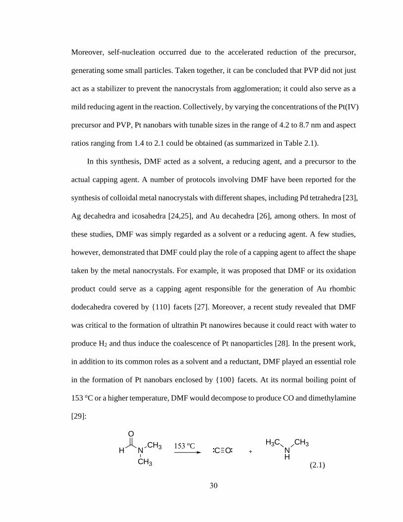
In this synthesis, DMF acted as a solvent, a reducing agent, and a precursor to the
actual capping agent. A number of protocols involving DMF have been reported for the
synthesis of colloidal metal nanocrystals with different shapes, including Pd tetrahedra [23],
Ag decahedra and icosahedra [24,25], and Au decahedra [26], among others. In most of
these studies, DMF was simply regarded as a solvent or a reducing agent. A few studies,
however, demonstrated that DMF could play the role of a capping agent to affect the shape
taken by the metal nanocrystals. For example, it was proposed that DMF or its oxidation
product could serve as a capping agent responsible for the generation of Au rhombic
dodecahedra covered by {110} facets [27]. Moreover, a recent study revealed that DMF
was critical to the formation of ultrathin Pt nanowires because it could react with water to
produce H2 and thus induce the coalescence of Pt nanoparticles [28]. In the present work,
in addition to its common roles as a solvent and a reductant, DMF played an essential role
in the formation of Pt nanobars enclosed by {100} facets. At its normal boiling point of
153 °C or a higher temperature, DMF would decompose to produce CO and dimethylamine
[29]:
(2.1)
H N
O
CH3
CH3
C O NH
H3C CH3153 ºC

31
It has been well documented that CO could serve as a capping agent selective toward
the Pt{100} facets [30,31]. A recent study on the synthesis of Pt nanocrystals by heating
Pt(acac)2 in oleic acid also demonstrated that CO arising from the decarbonylation of oleic
acid contributed to the formation of Pt nanocubes and nanobars enclosed by {100} facets
[32]. Besides the capping effect, CO could also act as a reducing agent in the synthesis,
facilitating the nucleation and growth processes. To confirm the presence of CO on the
surface, Fourier transform infrared (FT-IR) spectroscopy was performed on the as-
synthesized Pt nanobars. As shown in Figure 2.4, the FT-IR spectrum exhibited a well-
resolved band at 1990 cm-1 and a weak band at 1824 cm-1, corresponding to the linear and
bridging CO species, respectively [31]. The absence of these two bands on the FT-IR
spectra of PVP and DMF indicates that they were not from the residual PVP or DMF
remaining in the sample.
Figure 2.4. FT-IR spectra of the Pt nanobars prepared using the standard protocol,
confirming the presence of CO on the surface of the nanobars by showing well-resolved
CO bands corresponding to the linear and bridging configurations.

32
It can be concluded that the CO generated from the decomposition of DMF served as
a capping agent for the Pt{100} facets, and likely a reducing agent as well, contributing to
the formation of Pt nanobars. Different from previous reports on the synthesis of Pt
nanocubes, during which metal carbonyls [33,34] or CO gas flow [31] was introduced into
the reaction system, DMF in this simple route not only served as a solvent and a reductant,
but also generated CO in situ for the selective capping toward Pt{100}. As expected, when
DMF was replaced by benzyl alcohol and EG (Figure 2.5), Pt nanoparticles with nearly
spherical shapes were obtained, suggesting the pivotal role of DMF as a source of capping
agent in the formation of Pt nanobars.
Figure 2.5. TEM images of Pt nanocrystals prepared using the standard protocol, except
for using different solvents and reductants: (a) benzyl alcohol and (b) EG, respectively.
Since there is no intrinsic driving force for the Pt nanocrystals to grow into an
anisotropic shape lower in symmetry than its cubic lattice, I was interested in understanding
the mechanism responsible for the formation of the Pt nanobars. To gain insight into the

33
shape evolution and thus elucidate the mechanism underlying the anisotropic growth, the
nanocrystals formed at different time points during the standard synthesis were collected
and examined by TEM. Figure 2.6 shows TEM images of the intermediates that reveal the
morphological evolution of the nanocrystals from small seeds to nanobars.
Figure 2.6. TEM images of Pt nanocrystals obtained at different time points of a standard
synthesis: (a) 2, (b) 2.5, (c) 3.5, and (d) 6 h, respectively.
As shown in Figure 2.6a, a large number of small seeds were formed at the initial
stage of the synthesis (t=2 h). At t=2.5 h (Figure 2.6b), in addition to more particles with

34
sizes smaller than 3 nm, some relatively large bar-shaped particles and truncated cubes
were observed. As the reaction proceeded to t=3.5 h (Figure 2.6c), anisotropic growth
could be clearly identified as almost all of the nanocubes and the large particles evolved
into bar-shaped structures with an average aspect ratio of 1.2, while the number of small
particles decreased significantly. If the reaction was allowed to continue for 6 h (Figure
2.6d), all the small particles disappeared from the product, and the remaining Pt nanobars
exhibited sharp edges and corners, as well as an increase in aspect ratio to 1.6.
The presence of both bar-shaped and cubic nanocrystals in the sample obtained at
t=2.5 h led us to postulate that two different growth pathways could be involved in the
formation of Pt nanobars. A careful examination of the sample by high-resolution TEM
(HRTEM) revealed that the existence of the bar-shaped nanocrystals at the early stage of
the synthesis could be ascribed to the coalescence of the initially formed small Pt
nanoparticles. Figure 2.7a shows HRTEM image of two Pt nanocrystals featuring a bar-
like shape and continuous lattice fringes, validating their single-crystal structure. In
addition, the attachment of two adjacent small Pt nanoparticles was also clearly observed
in this sample (Figure 2.7, b-d), demonstrating the occurrence of particle coalescence. It is
noteworthy that nanoparticles formed at the beginning of the reaction would be single-
crystal while particles with twin defects could be generated as the reduction rate slowed
down due to the continuous consumption of the Pt precursor. However, in the presence of
Cl- ions released from the precursor and O2 dissolved in the solution, the twinned particles
would be selectively removed afterwards as a result of oxidative etching [11], leaving
behind single-crystal nanoparticles. From the thermodynamic point of view, the small Pt
nanoparticles with great mobility and high surface energy would like to collide and attach

35
to each other to reduce the total surface free energy. The two nanoparticles could rotate to
join with the lattice planes sharing the same crystallographic orientation (Figure 2.7b),
leading to the formation of larger nanocrystals with a single-crystal structure. On the other
hand, when the particles attach in an orientation-mismatched manner, as indicated by the
domain boundaries in between (Figure 2.7, c and d), defects would be included in the
resultant particle. Despite the polycrystallinity of the coalesced particle, recrystallization
could take place afterwards, during which the defects would be eliminated and the surface
of the nanocrystals would be smoothed via lattice rotation and atom migration in the
presence of capping agent. The reconstruction in structure and shape by recrystallization
has also been observed in the formation of Pd, Pt, and PtFe nanocrystals [13, 35,36].
Moreover, the involvement of recrystallization in the growth of nanobars is also suggested
by the fact that slight kinks were observed in Pt nanobars formed in the early stage of a
synthesis (e.g., the particle at the bottom of Figure 2.7a) while nanobars with well-defined
shape were obtained as the final product. Taken together, particle coalescence followed by
recrystallization of the attached particle in the presence of CO as a capping agent led to
symmetry breaking and elongation of Pt nanocrystals along one dimension, giving rise to
single-crystal nanobars enclosed by {100} facets. A similar mechanism involving the
particle coalescence was also suggested for the formation of Pd nanobars synthesized in an
aqueous solution by a different procedure [13].

36
Figure 2.7. HRTEM images of the product obtained at t=2.5 h into a standard synthesis
showing (a) small Pt nanocrystals with a bar-like shape and single-crystal structure and (b-
d) Pt nanoparticles coalesced in (b) an orientation matched and (c, d) mismatched manner.
The red dashed line outlines the profile of the particles while the arrow indicates the domain
boundary between the Pt nanoparticles.
In addition to particle coalescence, the formation of nanobars could also be attributed
to the anisotropic growth of nanocubes driven by localized oxidative etching. It was
reported that localized oxidative etching was capable of breaking the symmetry of a
nanocrystal through site-selective activation of the nanocrystal surface [14]. In this route,
oxidative etching occurs locally on a specific face of the nanocrystal in the presence of an
oxidant/ligand pair, such as O2 and halide ions released from the precursor or other

37
additives [11]. By selectively removing the capping agent from the surface of nanocrystals,
the activated site would be preferred for the deposition of atoms in the following growth,
resulting in symmetry breaking. To validate the role of localized oxidative etching in the
growth of Pt nanobars, I conducted the synthesis by following the standard protocol except
that different types of precursors were used and the atmosphere in the reaction was also
changed.
Figure 2.8. TEM images of Pt nanocrystals prepared using the standard procedure except
for the different precursors and atmospheres: (a) Pt(acac)2, (b) Pt(NH3)2Cl2, (c)
Na2PtCl6•6H2O together with bubbling Ar into the reaction solution, and (d)
Na2PtCl6•6H2O with the addition of 0.13 M citric acid, respectively. Insets are magnified
TEM images of individual Pt nanocrystals.

38
As shown in Figure 2.8a, by replacing Na2PtCl6 with Pt(acac)2 that contained no Cl-
ions, the as-obtained nanocrystals exhibited a nearly cubic shape. In contrast, the
nanocrystals prepared with Pt(NH3)2Cl2 as the precursor (Figure 2.8b) showed poor purity
and uniformity but still contained a portion of nanobars, demonstrating the significance of
Cl- ions in the generation of nanobars. Furthermore, I conducted the synthesis under an
inert atmosphere by bubbling the reaction solution with Ar to elucidate the role of oxygen.
Although it is difficult to completely exclude oxygen from the reaction solution, the as-
obtained products contained Pt nanocubes and nanobars with lower aspect ratios (Figure
2.8c), suggesting partial inhibition of anisotropic growth because of the reduced amount of
O2 in the reaction. Moreover, previous studies have reported that citric acid could
efficiently block oxidative etching in the synthesis of nanocrystals due to its capability to
react with and thus remove the adsorbed O2 [14,37]. Following this strategy, I added citric
acid at a concentration of 0.13 M to the standard synthesis. The resultant product was found
to consist of nanocubes and rounded nanoparticles (Figure 2.8d), indicating impeded
anisotropic growth due to the lack of oxidative etching. A possible explanation for the
presence of rounded nanoparticles is the strong binding of citric acid to Pt{111} facets,
which may hinder the adsorption of CO on Pt surface and thus the generation of {100}
facets. Taken together, the presence of O2 and Cl- ions released from the precursor is
essential to the formation of Pt nanobars, attesting the significant role of localized oxidative
etching in the induction of anisotropic growth.

39
Figure 2.9. Schematic illustration of the proposed growth pathways of Pt nanobars. With
CO serving as the capping agent for Pt{100} facets, the particle coalescence and localized
oxidative etching followed by preferential growth both contributed to the anisotropic
growth of Pt nanobars.
Based on the experimental results, the growth mechanism for Pt nanobars was
proposed as illustrated in Figure 2.9. At the beginning of the synthesis, the Pt(IV) precursor
was reduced by DMF at 160 °C with PVP serving as a co-reductant, generating nuclei that
then quickly evolved into small nanoparticles. Owing to the decomposition of DMF, CO
was produced and acted as a capping agent for Pt{100} facets. Afterwards, two distinctive
pathways could be taken for the generation of Pt nanobars. Due to the coalescence of the
initially formed small nanoparticles, nanocrystals with larger sizes and bar-shaped
morphology were formed, which later grew into nanobars with well-defined facets through
atom diffusion with the capping effect from CO.
Meanwhile, nanocubes were generated from the growth of the initially formed seeds,
and localized oxidative etching started to take place. The Cl- ions released from the
precursor and O2 in the solution could remove CO on the surface of a nanocube by
oxidation. Without the capping agent as a physical barrier to prevent the addition of atoms
onto the surface, this particular site was activated, favoring the deposition of Pt atoms.
Once heterogeneous nucleation selectively occurred on one of the side faces, the following

40
growth would preferentially take place on the activated surface, breaking the symmetry of
a nanocube. As a result, anisotropic growth was triggered, promoting the elongation along
one direction to generate nanobars. Taken together, the formation of Pt nanobars could be
ascribed to the coalescence of small particles in the early stage of the synthesis and the
preferential growth on specific faces activated by localized oxidative etching.
2.3 Conclusion
In summary, I have demonstrated a facile approach to the preparation of Pt nanobars
by heating a Pt(IV) precursor in DMF with PVP serving as a stabilizer and a mild reducing
agent. The involvement of DMF is critical to the generation of nanobars as DMF played
multiple roles in the synthesis: a solvent, a reducing agent, and a precursor for generating
the capping agent in situ. Using FT-IR spectroscopy, it was confirmed that CO, which was
produced from the decomposition of DMF at a high temperature of 160 ℃, served as the
capping agent to selectively adsorb on {100} facets for the formation of Pt nanobars. By
varying the concentrations of the Pt(IV) precursor and PVP involved in the synthesis, the
aspect ratio and size of the Pt nanobars could be readily tuned. It was found that the
anisotropic growth was induced by both particle coalescence during the early stage of the
synthesis and localized oxidative etching followed by further preferential growth. This
work offers not only a facile route to the synthesis of Pt nanobars with well-defined facets
and tunable aspect ratios, but also a deeper understanding of the growth mechanism
responsible for metal nanocrystals to take shapes lower in symmetry relative to the cubic
lattice.
2.4 Experimental Section

41
Chemicals and Materials. Sodium hexachloroplatinate(IV) hexahydrate
(Na2PtCl6·6H2O, 98%) and poly (vinyl pyrrolidone) (PVP, MW ≈ 55,000) were obtained
from Sigma-Aldrich. N,N-dimethylformamide (DMF, 99.8%) was purchased from Acros
Organics. All chemicals were used as received without further purification. Deionized
water with a resistivity of 18.2 MΩ·cm was used throughout the experiments.
Synthesis of Pt Nanobars. In a standard procedure, 20 mg of Na2PtCl6·6H2O and
100 mg of PVP were dissolved in 10 mL of DMF under ultrasonication. The as-obtained
yellow solution was stored in a tightly-capped 20-mL glass vial and heated in an oil bath
held at 160 ℃ for 16 h under magnetic stirring. The solid product was collected by
centrifugation at 6,000 rpm for 10 min and then washed with water twice to remove excess
PVP. The Pt nanobars were then re-dispersed in water for further characterization.
Characterization. TEM images were taken using a Hitachi HT-7700 microscope
operated at 120 kV. HRTEM images were captured on a Cs-corrected FEI Titan 80 kV
TEM at the Oak Ridge National Laboratory. FT-IR spectra were performed on a Varian
640 spectrometer through the use of an attenuated total reflectance (ATR) accessory. The
Pt nanobars for FT-IR analysis were collected by centrifugation and re-dispersed in ethanol
without further treatment. The sample was drop-cast on top of the crystal and dried under
ambient conditions. The spectra were recorded in the range of 4000-400 cm-1 with a
resolution of 8 cm-1.
2.5 Notes to Chapter 2
Part of this Chapter is adapted from the paper “A Simple Route to the Synthesis of Pt
Nanobars and the Mechanistic Understanding of Symmetry Reduction” published in
Chemistry-A European Journal [38].

42
2.6 References
[1] Shi, Y.; Lyu, Z.; Zhao, M.; Chen, R.; Nguyen, Q. N.; Xia, Y. Chem. Rev. 2021, 121,
649−735.
[2] Zada, A.; Muhammad, P.; Ahmad, W.; Hussain, Z.; Ali, S.; Khan, M.; Khan, Q.;
Maqbool, M. Adv. Funct. Mater. 2020, 30, 1906744.
[3] Dreaden, E. C.; Alkilany, A. M.; Huang, X.; Murphy, C. J.; El-Sayed, M. A. Chem.
Soc. Rev. 2012, 41, 2740−2779.
[4] Zhang, J.; Kuang, Q.; Jiang, Y.; Xie, Z. Nano Today 2016, 11, 661−677.
[5] Choi, S.-I.; Herron, J. A.; Scaranto, J.; Huang, H.; Wang, Y.; Xia, X.; Lv, T.; Park,
J.; Peng, H.-C.; Mavrikakis, M.; Xia, Y. ChemCatChem 2015, 7, 2077−2084.
[6] Zhang, Q.; Moran, C. H.; Xia, X.; Rycenga, M.; Li, N.; Xia, Y. Langmuir 2012, 28,
9047−9054.
[7] Li, Y.; Bian, T.; Du, J.; Xiong, Y.; Zhan, F.; Zhang, H.; Yang, D. CrystEngComm
2014, 16, 8340−8343.
[8] Lu, Y.; Jiang, Y.; Chen, W. Nano Energy 2013, 2, 836−844.
[9] Li, M.; Zhao, Z.; Cheng, T.; Fortunelli, A.; Chen, C.-Y.; Yu, R.; Zhang, Q.; Gu, L.;
Merinov, B. V.; Lin, Z.; Zhu, E.; Yu, T.; Jia, Q.; Guo, J.; Zhang, L.; Goddard III,
W. A.; Huang, Y.; Duan, X. Science 2016, 354, 1414−1419.
[10] Huang, H.; Ruditskiy, A.; Choi, S.-I.; Zhang, L.; Liu, J.; Ye, Z.; Xia, Y. ACS Appl.
Mater. Interfaces 2017, 9, 31203−31212.
[11] Xia, Y.; Xiong, Y.; Lim, B.; Skrabalak, S. E. Angew. Chem. Int. Ed. 2009, 48,
60−103.
[12] Tao, A. R.; Habas, S.; Yang, P. Small 2008, 4, 310−325.
[13] Lim, B.; Kobayashi, H.; Camargo, P. H. C.; Allard, L. F.; Liu, J.; Xia, Y. Nano Res.
2010, 3, 180−188.
[14] Xiong, Y.; Cai, H.; Wiley, B. J.; Wang, J.; Kim, M. J.; Xia, Y. J. Am. Chem. Soc.
2007, 129, 3665−3675.
[15] Zhou, S.; Mesina, D. S.; Organt, M. A.; Yang, T.-H.; Yang, X.; Huo, D.; Zhao, M.;
Xia, Y. J. Mater. Chem. C 2018, 6, 1384−1392.
[16] Yu, Y.; Zhao, Y.; Huang, T.; Liu, H. Mater. Res. Bull. 2010, 45, 159−164.

43
[17] Lim, B.; Jiang, M.; Tao, J.; Camargo, P. H. C.; Zhu, Y.; Xia, Y. Adv. Funct. Mater.
2009, 19, 189−200.
[18] Wiley, B. J.; Chen, Y.; McLellan, J. M.; Xiong, Y.; Li, Z.-Y.; Ginger, D.; Xia, Y.
Nano Lett. 2007, 7, 1032−1036.
[19] Wiley, B.; Sun, Y.; Xia, Y. Acc. Chem. Res. 2007, 40, 1067−1076.
[20] Carrera-Cerritos ,R.; Ponce de León, C.; Ledesma-García, J.; Fuentes-Ramírez, R.;
Arriaga, L. G. RSC Adv. 2014, 4, 16632−16640.
[21] Zhang, K.; Xiang, Y.; Wu, X.; Feng, L.; He, W.; Liu, J.; Zhou, W. Xie, S. Langmuir
2009, 25, 1162−1168.
[22] Xiong, Y.; Washio, I.; Chen, J.; Cai, H.; Li, Z.-Y.; Xia, Y. Langmuir 2006, 22,
8563−8570.
[23] Zhang, Y.; Wang, M.; Zhu, E.; Zheng, Y.; Huang, Y.; Huang, X. Nano Lett. 2015,
15, 7519−7525.
[24] Tsuji, M.; Ogino, M.; Matsuo, R.; Kumagae, H.; Hikino, S.; Kim, T.; Yoon, S.-H.
Cryst. Growth Des. 2010, 10, 296−301.
[25] Gao, Y.; Jiang, P.; Song, L.; Wang, J. X.; Liu, L. F.; Liu, D. F.; Xiang, Y. J.; Zhang,
Z. X.; Zhao, X. W.; Dou, X. Y.; Luo, S. D.; Zhou, W. Y.; Xie, S. S. J. Cryst. Growth
2006, 289, 376−380.
[26] Sanchez-Iglesias, A.; Pastoriza-Santos, I.; Perez-Juste, J.; Rodríguez-Gonzalez,
B.; García de Abajo, F. J.; Liz-Marzan, L. M. Adv. Mater. 2006, 18, 2529−2534.
[27] Jeong, G. H.; Kim, M.; Lee, Y. W.; Choi, W.; Oh, W. T.; Park, Q. H.; Han, S. W.
J. Am. Chem. Soc. 2009, 131, 1672−1673.
[28] Liu, Y.; Wang, C.; Wang, W.; Guo, R.; Bi, W.; Guo, Y.; Jin, M. Nanoscale 2019,
11, 14828−14835.
[29] S. Creager, Solvents and Supporting Electrolytes in Handbook of Electrochemistry,
(Ed: C. G. Zoski) Elsevier, Amsterdam, The Netherlands, 2007, pp. 57−72.
[30] Chen, G.; Tan, Y.; Wu, B.; Fu, G.; Zheng, N. Chem. Commun. 2012, 48,
2758−2760.
[31] Wu, B.; Zheng, N.; Fu, G. Chem. Commun. 2011, 47, 1039−1041.
[32] Xie, M.; Lyu, Z.; Chen, R.; Xia, Y. Chem. Eur. J. 2020. 26, 15636−15642.
[33] Wang, C.; Daimon, H.; Lee, Y.; Kim, J.; Sun, S. J. Am. Chem. Soc. 2007, 129,
6974−6975.

44
[34] Kang, Y.; Pyo, J. B.; Ye, X.; Diaz, R. E.; Gordon, T. R.; Stach, E. A.; Murray, C.
B. ACS Nano 2013, 7, 645−653.
[35] Zheng, H.; Smith, R. K.; Jun, Y.; Kisielowski, C.; Dahmen, U.; Alivisatos, A. P.
Science, 2009, 324, 1309−1312.
[36] Liao, H.-G.; Cui, L.; Whitelam, S.; Zheng, H. Science, 2012, 336, 1011−1014.
[37] Xiong, Y.; McLellan, J. M.; Yin, Y.; Xia, Y. Angew. Chem. Int. Ed. 2007, 46,
790−794.
[38] Chen, R.; Nguyen, Q. N.; Zhao, M.; Chen, Z.; Chi, M.; Xia, Y. Chem. Eur. J.
2021. 27, 2760−2766.

45
CHAPTER 3
CONTINUOUS AND SCALABLE SYNTHESIS OF PLATINUM
MULTIPODS WITH ENHANCED ELECTROCATALYTIC
ACTIVITY TOWARD THE OXYGEN REDUCTION REACTION
3.1 Introduction
Nanocrystals comprised of Pt and its alloys are the catalysts of choice for accelerating
the sluggish kinetics of oxygen reduction, a reaction key to the operation of proton-
exchange membrane fuel cells (PEMFCs) [1]. Although PEMFCs hold great promise for
clean energy, their large-scale commercialization still remains challenging owing to the
scarcity and ever-increasing cost of Pt. By controlling the size, shape, composition,
morphology, and structure of Pt-based nanocrystals, one can substantially enhance their
catalytic activities to achieve sustainable use in PEMFCs. To date, Pt nanocrystals with a
wide variety of shapes and morphologies have been extensively studied as electrocatalysts
for the oxygen reduction and other electrocatalytic reactions, including solid polyhedrons
[2-4], hollow nanocages [5], nanodendrites [6, 7], and multipods [8], among others. In
particular, Pt multipods are of interest due to their intrinsically high specific surface area
and thus efficient utilization of atoms. Platinum and Pt-based multipods, such as Pt
octopods [9], PtIr tripods [8], PtNi multipods [10] and PtCu hexapods [11] have been
reported with superior performance towards various electrocatalytic reactions. However,
most of the protocols for the synthesis of branched noble-metal nanocrystals are too
complicated due to the involvement of etchants [12], templates [13] and/or other additives

46
to induce the anisotropic growth [14]. There is a need to develop a much simplified
procedure capable of generating Pt multipods with controlled sizes and morphologies.
In addition to the required improvement in catalytic performance and the
simplification of synthetic protocols, another critical issue hindering the commercialization
of Pt-based catalysts is the existing gap between academic studies and industrial
applications. For example, it is still challenging to produce catalysts based on facet-
controlled Pt nanocrystals at an industrially relevant scale without affecting the quality and
properties of the nanocrystals. For most of the syntheses based on a batch reactor, such as
a vial or flask, the throughput was typically limited to tens of milligrams of Pt per batch
and the synthesis usually took several hours to days [3,15]. Although it seems
straightforward to increase the throughput by enlarging the batch reactor, the quality of the
products is often degraded because the experimental parameters will be affected when the
volume of the reaction solution is increased. The collection of products from multiple runs
of a batch synthesis to increase the quantity is also not favorable owing to the lack of batch
to batch reproducibility. Therefore, it is difficult for the batch-based synthesis to meet the
requirement of large quantity for a commercial application.
To address the aforementioned issues, synthesis in a continuous flow reactor has
recently emerged as a practical solution to the scalable production of nanocrystals with a
tight control over the size, shape, and morphology [16,17]. As a signature of continuous
flow, the total volume of the production (Vtotal) can be expressed as:
𝑉total = 𝑞 × 𝑡
where q is the volume flow rate and t is the duration of a synthesis. This linear relationship
allows us to easily scale up the throughput by increasing the duration of a synthesis instead
47
of adjusting other experimental parameters. Although the one-phase, continuous flow
synthesis usually requires well-mixed solution beforehand, it is easier to operate and
eliminates the need of a mixer when compared with the droplet [18] and plug reactors [19]
with oil or gas acting as the carrier phase. With these attractive features, continuous flow
has been successfully applied to the scalable production of a number of colloidal
nanocrystals with well-controlled sizes, shapes, and compositions [18-25].
In this work, I report a facile technique for the scalable production of Pt multipods
with small sizes and a highly branched structure in a continuous flow system. The synthesis
of the Pt multipods is simplified by using oleylamine (OAm) as the solvent, surfactant, and
reducing agent. As a linearly scalable platform, the continuous flow system can increase
the throughput of the production to 17 mg of Pt per hour without any degradation to the
quality and properties of the products. Based on an investigation of the time-dependent
evolution of morphology, it was believed that the anisotropic growth of Pt multipods can
be attributed to a combination of the fast, autocatalytic surface growth and small particle
attachment. When benchmarked against a commercial Pt/C catalyst, the Pt multipods/C
catalysts exhibit enhanced electrocatalytic activity toward ORR.
3.2 Results and Discussion
In a standard synthesis, Pt(acac)2 was first dissolved in OAm at an elevated
temperature and then the solution was cooled down to room temperature before being
introduced into the fluidic device. In this case, OAm not only worked as a solvent and
surfactant, but also served as a mild reducing agent. It should be mentioned that Pt(acac)2
was dissolved at a carefully selected temperature of 70 °C, at which a homogenous solution
was obtained while the precursor would not be reduced by OAm. Afterwards, the reaction

48
solution was injected into the fluidic device comprised of a polytetrafluoroethylene (PTFE)
tube immersed in an oil bath held at 180 °C. The residence time was set to 15 min by
controlling the length of the PTFE tube immersed in the oil bath and the liquid flow rate.
Figure 3.1. (a) Schematic illustration of the fluidic device used for a continuous flow
synthesis. (b) Typical TEM image of the Pt multipods synthesized in the continuous flow
reactor. (c-e) TEM images of individual Pt multipods with three, four, and five branches,
respectively. The scale bars are 5 nm.
Figure 3.1a shows a schematic illustration of the setup used for the synthesis of Pt
multipods. When the solution entered the reaction zone, its color gradually turned from
bright light yellow to dark brown and finally black, indicating the formation of Pt
nanocrystals. Figure 3.1b shows a representative TEM image of the Pt multipods
synthesized in the continuous flow reactor. The as-prepared Pt multipods contained a mix
of nanoparticles with different numbers of branches, typically varying from 2 to 6 (see

49
Figure 3.1, c-e for individual Pt multipods with three, four, and five branches). The overall
sizes of the multipods were relatively small, ranging from 3-5 nm and 2-3 nm for the length
and width of the branches, respectively. Using the fluidic device, it was feasible to
continuously produce the Pt multipods at a throughput of about 17 mg per hour, which was
calculated based on the production rate of 0.5 mL product solution per minute. The
conversion yield was determined using inductively-coupled plasma mass spectrometry
(ICP-MS).
I further characterized the structures of the Pt multipods in detail by means of HRTEM.
Figure 3.2, a and b show the high-angle annular dark-field scanning transmission electron
microscopy (HAADF-STEM) and HRTEM images of an individual Pt tripod with a highly-
ordered lattice fringe pattern. As indicated by the atomic-resolution HAADF-STEM image
in Figure 3.2c, the polycrystalline structure of the tripod was confirmed by the grain
boundary occurring at one of the tips. The measured fringe spacing of 0.23 nm could be
assigned to the {111} planes, and the other spacing of 0.20 nm corresponded to the {100}
planes. This result revealed that the growth of the branches was along the <111> or <100>
direction. The observation appeared to agree with a previous study in that the growth of Pt
nanoparticles was predominant in either <111> or <100> direction [26]. Figure 3.2d shows
a typical X-ray diffraction (XRD) pattern of the as-prepared Pt multipods. The diffraction
peaks appearing at 2θ values of 39.8 °, 46.3 °, 67.6 ° and 81.5° could be assigned to the
diffraction from (111), (200), (220), and (311) planes of fcc Pt (space group: Fm3m).

50
Figure 3.2. (a) HAADF-STEM and (b) HRTEM images of the Pt multipods synthesized
in the continuous flow reactor. (c) Atomic-resolution HAADF-STEM image of the region
highlighted by the red box in (a), showing the exposed {111} and {100} planes and a grain
boundary. (d) Powder XRD pattern of the Pt multipods.
As there is no intrinsic driving force for the noble-metal nanocrystals with an fcc
structure to grow into highly branched structures [27], the formation mechanism of Pt
multipods is of particular interest. To better understand the growing process, the
intermediates formed at different reaction stages should be characterized. However, this is
difficult to accomplish when the Pt multipods were synthesized in continuous flow because
I could not sample the solution flowing through the PTFE tube. Therefore, I tried to monitor

51
the growth process in a batch reactor. In this case, Pt multipods were synthesized in a glass
vial under the same experimental conditions as those for continuous flow reactor to
examine whether their shape and size would be affected. A TEM image of the Pt multipods
synthesized in a vial is shown in Figure 3.3, which had essentially the same morphology
as those produced in continuous flow. Thus, the reaction in a vial could be utilized to track
the evolution of morphology for the Pt multipods.
Figure 3.3. TEM image of the Pt multipods synthesized in a glass vial using the same
reaction parameters as for the continuous flow reactor.
During a standard synthesis in a vial, aliquots were sampled at different time points
and the corresponding TEM images of the intermediates are shown in Figure 3.4. After 10
min into the synthesis, small seeds were formed with an average diameter around 2.2 nm.

52
At t=13 min, the anisotropic growth took place. Some of the nanocrystals already showed
3 or 4 branches with an average length approaching 3.6 nm. Almost all of the Pt
nanocrystals developed a branched structure at t=15 min, with varying numbers of branches
but similar sizes (3-5 nm and 2-3 nm for the length and width, respectively). When the
reaction continued for 4 h, an increase in length and width could be obviously observed for
each branch rather than the occurrence of secondary branching on the primary pods. In
other words, no additional branching would occur if the reaction time was prolonged.
There are already a large number of methods developed for the synthesis of branched
metal nanocrystals and some reasonable understandings of the growth mechanism have
been proposed, including kinetically controlled overgrowth, aggregation-based growth,
and heterogeneous seeded growth, among others [28]. For example, it was reported that Pt
planar tripods could be obtained through preferred overgrowth on the seeds with stacking
faults [29]. For the synthesis reported in this work, the experimental system is much
simpler as it consists of only Pt(acac)2 precursor and OAm. This simplicity requires us to
fully understand the multiple roles played by OAm in the synthesis. It is well known that
OAm can form coordination complex with metal precursors such as Pt(acac)2. The amine
group coordinates with Pt2+, leading to the formation of Pt(OAm)4(acac)2, which undergoes
a slow, first-order reduction and then a fast, autocatalytic surface growth [30]. This is
consistent with our observation from the TEM images in that plenty of small Pt
nanoparticles were formed at 10 min into the synthesis, which then quickly grew to
branched structures in the following 5 min.

53
Figure 3.4. Evolution of the Pt multipods with time. TEM images of the Pt multipods
synthesized in a batch reactor at 180 °C for a) 10, b) 13, c) 15, and d) 240 min, respectively.
The average lengths of the branches were 2.2, 3.6, 4.8, and 7.4 nm, respectively.
In fact, comparing to a polyhedral nanocrystal with the same volume, a multipod has
a larger surface area and thus, higher surface energy, making it less favored
thermodynamically. However, the seeds formed at the initial stage of the reaction was
switched to autocatalytic growth, facilitating the formation of Pt adatoms and leading to
increased growth rate beyond the thermodynamically controlled regime. Additionally, the
diffusion rate of the Pt adatoms was relatively slow due to the high viscosity of OAm. The

54
newly-formed adatoms would quickly nucleate on multiple sites of the seeds rather than
migrate on the surface to minimize the surface energy because of the faster deposition rate
relative to the diffusion rate. As a result, anisotropic growth occurred and this led to the
formation of Pt multipods.
In addition to the multi-directional growth, the coalescence and attachment of small
particles could also be of significance during the growth of Pt multipods. Owing to the
great mobility and high energy the small particles have, the initially formed Pt
nanoparticles with an average diameter of 2.2 nm could collide at a high frequency and
reduce the total surface energy by pairing with each other. The attachment of small particles
was confirmed by the atomic resolution HAADF-STEM image in Figure 3.2c, where a
grain boundary separating two sets of planes was observed. It should be mentioned that
since it is not feasible to precisely control the number of small particles attached to the seed
and the nucleation sites on the seed, the Pt multipods tended to have different numbers of
branches. The multipods with only one type of branches, such as Pd-Cu tripods [31] and
Pd octapods [32], can be prepared through the involvement of well-defined seeds and the
following site-selective growth, which is different from the mechanism I report here.
With the passage of time, only the width and length of the branches were increased
instead of secondary branching or the formation of the foam-like nanodendrites. A
plausible reason is that the newly formed small particles can be captured more effectively
by the tips of the already developed branches, preventing the formation of hierarchical
structures. Another possibility is that hierarchical structures are not favored in terms of
thermodynamics because of their even higher surface area and surface energy comparing
to the primary pods.

55
Figure 3.5. Typical TEM image of the carbon-supported Pt multipods before the
electrochemical measurement.
Among metal nanocrystals with different morphologies, multipods are of particular
interest for electrocatalysis because of the particularly high surface area they exhibit owing
to the highly branched structure. I evaluated the electrocatalytic properties of the carbon-
supported Pt multipods (Figure 3.5) toward ORR by benchmarking against a commercial
Pt/C catalyst. Figure 3.6a shows a cyclic voltammetry curve of the carbon-supported Pt
multipods. By measuring the average charges associated with the adsorption and
desorption of hydrogen in the region of 0.05–0.40 V vs. reversible hydrogen electrode
(RHE), the specific electrochemically active surface area (ECSA) of the catalysts was
derived. The specific ECSA of Pt multipods/C catalyst (68.5 m2 gPt-1) was comparable to
that of the commercial Pt/C catalyst (57.7 m2 gPt-1) although the Pt multipods were larger

56
in size than the Pt nanocrystals in Pt/C. This could be attributed to the larger surface area
exposed by the branched structure.
Figure 3.6. Electrocatalytic properties of the Pt multipods toward the oxygen reduction
reaction. (a) Cyclic voltammetry curves of the carbon-supported Pt multipods and a
commercial Pt/C catalyst recorded in a N2-saturated HClO4 solution at a scanning rate of
50 mV/s. (b) ORR polarization curves for the catalysts measured in an O2-saturated HClO4
solution at a scanning rate of 10 mV/s and a rotation speed of 1600 rpm. The currents were
normalized to the geometric area of the rotating disk (0.196 cm2). (c, d) Plots of mass
activity and specific activity given as kinetic current density (jk) normalized to the Pt mass
and ECSA of the catalyst, respectively. The color scheme used in (a) applies to all panels.
Figure 3.6b shows the positive-going ORR polarization curves for the catalysts
measured in an O2-saturated HClO4 solution, demonstrating the more positive onset and
half-wave potentials of the Pt multipods/C relative to the commercial Pt/C. The kinetic

57
current was calculated based on Koutecky-Levich equation and the specific activity (jk,
specific) and mass activity (jk, mass) were then obtained by normalizing kinetic current against
the ECSA and Pt mass, respectively.
Table 3.1. Comparison of the specific ECSAs, SAs, and MAs toward ORR for the Pt
multipods/C, and commercial Pt/C catalysts.
Sample Specific ECSA
(m2 gPt-1)
MA at 0.9 VRHE
(A mgPt-1)
SA at 0.9 VRHE
(mA cm-2)
Pt multipods/C 68.5 0.37 0.55
Commercial Pt/C 57.7 0.15 0.26
The enhanced ORR activity of Pt multipods/C was confirmed by the Tafel Plots
shown in Figure 3.6, c and d. In the potential region of 0.86–0.94 V with a reference to
RHE (VRHE), both the mass and specific activities of Pt multipods/C catalysts were
enhanced compared to commercial Pt/C catalyst. Particularly, as shown in the insets of
Figure 3.6, c and d, the Pt multipods/C catalyst showed a mass activity (MA) of 0.37 A
mgPt-1 at 0.9 VRHE, which was 2.5 times greater than that of the commercial Pt/C catalyst
(0.15 A mgPt-1). The specific activity (SA) of the Pt multipods/C catalyst was more than
doubled at 0.9 VRHE (0.55 mA cm-2) relative to that of the commercial Pt/C (0.26 mA cm-
2). The results were summarized in Table 3.1. Using the Koutecky-Levich method (see
Figure 3.7), the electron transfer number of ORR under the catalysis of Pt multipods was
calculated to be 4.4 (≈ 4), which is consistent with a previous study of the Pt/C catalyst [33].

58
Figure 3.7. (a) Rotating disk voltammograms of Pt multipods/C catalyst in an O2-saturated
HClO4 solution with various rotation speeds at a scanning rate of 10 mV/s. The currents
were normalized to the geometric area of the rotating disk (0.196 cm2). (b) Koutecky–
Levich plots (j-1 vs. ω-1/2) for Pt multipods at 0.3 V.
The above results indicate the accelerated ORR kinetics on the surface of the Pt
multipods, which can be attributed to the higher surface area intrinsic to the open branched
structure. Besides, as shown in Figure 3.2c, the surface of the Pt multipods was not smooth
and bounded by neither {111} nor {100} facets. This provides high possibility for the
exposure of high-index facets, which generally contain a high density of stepped surface
atoms with higher ORR activity [34,35]. In a number of studies, it was reported that some
structural defects, such as grain boundaries, could also contribute to the enhancement in
ORR electrocatalytic performance [36-38]. For instance, it was reported that the ORR rate
could be greatly enhanced by the hollow PtNi/C catalyst with grain boundaries and
vacancies on the nanoparticles [36]. The better electrocatalytic activity could be possibly
ascribed to the optimized binding of ORR intermediates and modified electronic structure
of Pt atoms, which should be related to the lattice distortion and a less dense atomic
arrangement within the structural defects. As we discussed previously, grain boundaries
are formed during the growing process of Pt multipods because of the small Pt particles

59
attachment. These structural defects could serve as highly active sites for ORR, leading to
faster ORR kinetics as I observed.
Figure 3.8. (a) Cyclic voltammetry (CV) curves of the carbon-supported Pt multipods
before and after the accelerated durability test. The durability test was carried out in an O2-
saturated HClO4 solution with the potential sweeping between 0.6 and 1.1 VRHE at a
scanning rate of 100 mV/s. The CV curves were recorded in a N2-saturated HClO4 solution
at a scanning rate of 50 mV/s. (b) Comparison of the mass activity of the Pt multipods/C
catalyst before and after the accelerated durability test.
I also performed accelerated durability tests by applying linear potential sweeps in the
range of 0.6 to 1.1 VRHE in an O2-saturated HClO4 solution to evaluate the stability of the
catalysts. As shown in Figures 3.8 and 3.9, after 5,000 cycles of sweeping, the Pt multipods
exhibited a loss of 24% in specific ECSA and 27% in mass activity. In comparison, both
the specific ECSA and the mass activity of the commercial Pt/C dropped by 28%,
suggesting that the Pt multipods had slightly better stability than the commercial Pt/C
catalyst. After 10,000 cycles, the specific ECSA of Pt multipods dropped by 33% and the
mass activity decreased by 42%. Considering the initial Pt multipods/C catalyst showed
2.5 folds enhancement in the mass activity relative to commercial Pt/C, the mass activity

60
of Pt multipods after 10,000 cycles was still slightly higher than that of the pristine
commercial Pt/C.
Figure 3.9. (a) CV curves of the commercial Pt/C catalyst before and after the accelerated
durability test. The durability test was carried out using the same test parameters as for the
Pt multipods/C catalyst. (b) Comparison of the mass activity of the commercial Pt/C
catalyst before and after the accelerated durability test.
3.3 Conclusion
I have demonstrated a continuous and scalable route to the synthesis of Pt multipods
with a branched structure in a fluidic device. The size of the Pt multipods could be
controlled in the range of 3-5 nm and 2-3 nm for the length and width, respectively, of the
branches by controlling the residence time. Using the continuous flow system, it was
feasible to linearly increase the throughput of the production to up to 17 mg of Pt multipods
per hour, without compromising the quality of the synthesized nanocrystals. The growing
mechanism of the Pt multipods was investigated and it was proposed that a combination of
fast autocatalytic surface growth and small particles attachment contributed to the

61
anisotropic growth. Owing to the open branched structure, Pt multipods/C catalyst
exhibited enhanced ORR activity comparing to commercial Pt/C catalyst despite of their
relatively larger sizes. I believe that this work holds the promise for scaling up the
production of Pt nanostructures to be used as ORR catalysts for PEMFCs. The continuous
flow method can also be extended to the production of multi-metal nanostructures, as we
have demonstrated for the synthesis of Pt-Ni alloy nanoscale octahedra [25].
3.4 Experimental Section
Chemicals and Materials. Platinum acetylacetonate (Pt(acac)2, 97%), oleylamine
(OAm, 70%), butylamine (99.5%), anhydrous ethanol (200 proof), perchloric acid (70%)
and Nafion perfluorinated resin solution (5%) were all obtained from Sigma-Aldrich.
Toluene (99.5%) was ordered from Acros Organics. Isopropyl alcohol (IPA) was
purchased from BDH. All chemicals were used as received without further purification.
Synthesis of Pt Multipods in a Continuous Flow Reactor. Before the synthesis, 10
mg of Pt(acac)2 (0.025 mmol) and 5 mL OAm were mixed in a vial and then heated to
70 °C for 10 min to dissolve the solid. Afterwards, the mixture was cooled down to room
temperature before being injected into the fluidic device. The fluidic device was assembled
from commercially available materials, including a PTFE tube with an inner diameter of
1.58 mm and a length of 5.5 m, a plastic syringe, and a syringe pump. In a standard
synthesis, the PTFE tube was immersed in an oil bath held at 180 °C. The precursor
solution was injected into the PTFE tube at a flow rate of 0.5 mL min-1. The residence time
was set to 15 min, which was determined by the flow rate and the length of the tube. The
product was collected by centrifugation. Ethanol (5 mL) was added into the reaction
solution and the mixture was then centrifugated at 6000 rpm for 10 min to remove the

62
supernatant. The as-obtained Pt multipods were dispersed in toluene for further
characterization.
Characterization. TEM images were taken using a Hitachi HT7700 microscope
operated at 100 kV. The metal contents analysis for the as-prepared catalyst was performed
by ICP-MS (Perkin-Elmer, NexION 300Q). HAADF-STEM and HRTEM were performed
using an HT2700 aberration-corrected STEM (Hitachi) operated at 200 kV. Before
imaging, the sample was cleaned to remove the remaining surfactants via treatment in a
Hitachi Zone cleaner for 30 min at a pressure setting of 30. XRD pattern was recorded
using an X'Pert PRO Alpha-1 diffractometer (PANalytical, Almelo, Netherlands) with a
ceramic copper tube source.
Preparation of Pt Multipods/C Catalyst. In a standard procedure, the as-prepared
Pt multipods from a standard synthesis were dispersed in butylamine (0.5 mg mL-1) and
then mixed with carbon black (Vulcan XC-72; CABOT, suspended in butylamine at 1 mg
mL-1) under ultrasonication for 2 h. Afterwards, the mixture was stirred at room
temperature overnight, collected by centrifugation at 12000 rpm for 15 min, and then
washed with ethanol five times. The final catalyst was dried in an oven set at 70 °C for 2 h
prior to the electrochemical measurement.
Preparation of Working Electrodes. In a typical procedure, the catalyst ink with a
concentration of 1 mg mL-1 was prepared by dispersing the carbon-supported Pt multipods
in a mixture of IPA and 5% Nafion (VIPA: V5%Nafion=1:0.01) under ultrasonication. The Pt
loading of the catalyst was set to 16%, which was confirmed by ICP-MS. An aliquot of the
catalyst suspension containing 1 μg of the carbon-supported Pt multipods was drop-cast on
a clean glassy carbon electrode with a geometric area of 0.196 cm2 and allowed to dry

63
under ambient conditions. For comparison, the ink of a commercial Pt/C catalyst (20 wt%
3.2-nm Pt nanoparticles on Vulcan XC-72 carbon support; E-TEK) was prepared using the
same protocol and the loading amount of Pt on the electrode was also set to 1 μg.
Electrochemical Measurements. Electrochemical measurements were performed
using a glassy carbon rotating disk electrode (RDE, Pine Research Instrumentation)
connected to an electrochemical workstation (CHI 600E, CH Instruments). A HydroFlex
reference electrode and a Pt mesh were used as the reference and counter electrodes,
respectively. The electrolyte was 0.1 M perchloric acid aqueous solution. Cyclic
voltammetry curves were recorded in a N2-saturated HClO4 solution between 0.05-1.1
VRHE at a scanning rate of 50 mV/s. The specific ECSA of the catalyst was calculated by
measuring the average charges associated with the adsorption and desorption of hydrogen
in the region of 0.05–0.40 VRHE after double-layer correction, with the assumption that the
charge required for monolayer adsorption of hydrogen on a Pt surface is 210 μC cm-2. The
oxygen reduction reaction test was carried out in an O2-saturated HClO4 solution at a
scanning rate of 10 mV/s and a rotation speed of 1600 rpm. The data were corrected by
100% IR drop compensation. The kinetic current was calculated based on the following
equation, which was derived from Koutecky-Levich equation:
𝑗𝑘 =𝑗 𝑙 × 𝑗
𝑗𝑙 − 𝑗
where jk is the kinetic current, jl is the diffusion-limiting current and j is the experimentally
measured current at 0.9 V. The kinetic current was finally normalized to the Pt loading
amount and ECSA to obtain the mass and specific activities, respectively. In the ORR
polarization curves, the current densities were normalized to the geometric area of the
rotating disk electrode (0.196 cm2). For the accelerated durability test, 8 µL of the catalyst

64
suspension was drop-cast on a glassy carbon electrode. The CV and ORR polarization
curves were recorded after sweeping 5,000 and 10,000 cycles in the range of 0.6 to 1.1
VRHE in an O2-saturated HClO4 solution at a scanning rate of 100 mV/s. Rotating disk
voltammograms of Pt multipods were recorded in an O2-saturated HClO4 solution with
different rotation speed at a scanning rate of 10 mV/s. The calculation of electron transfer
number for ORR was based on the slope of the Koutecky-Levich plot (j-1 vs. ω-1/2)and the
equations:
1
𝑗=
1
𝑗𝑘+
1
𝐵𝜔1/2
𝐵 = 0.62𝑛𝐹𝐶𝑂𝐷𝑂2/3𝑣−1/6
where j is the measured current density, jk is the kinetic current, ω is the angular velocity
of the disk, n is the electron transfer number in oxygen reduction, F is the Faraday constant
(F = 96485 C mol-1), Co is the bulk concentration of O2 (Co = 1.18×10⁻⁶ mol cm-3 in 0.1 M
HClO4 solution), Do is the diffusion coefficient of O2 (Do = 1.9×10⁻⁵ cm2 s-1 in 0.1 M HClO4
solution), and v is the kinematic viscosity of the electrolyte (v = 8.93×10⁻³ cm2 s-1 in 0.1 M
HClO4 solution).
3.5 Notes to Chapter 3
Part of this Chapter is adapted from the paper “Continuous and Scalable Synthesis of
Pt Multipods with Enhanced Electrocatalytic Activity toward the Oxygen Reduction
Reaction” published in ChemNanoMat [39].
3.6 References
[1] Sui, S.; Wang, X.; Zhou, X.; Su, Y.; Riffat, S.; Liu, C. J. J. Mater. Chem. A 2017,
5, 1808–1825.

65
[2] Wang, X.; Vara, M.; Luo, M.; Huang, H.; Ruditskiy, A.; Park, J.; Bao, S.; Liu, J.;
Howe, J.; Chi, M.; Xie, Z.; Xia, Y. J. Am. Chem. Soc. 2015, 137, 15036–15042.
[3] Huang, X.; Zhao, Z.; Cao, L.; Chen, Y.; Zhu, E.; Lin, Z.; Li, M.; Yan, A.; Zettl, A.;
Wang, Y.M.; Duan, X.; Mueller, T.; Huang, Y. Science 2015, 348, 1230–1234.
[4] Wu, J.; Qi, L.; You, H.; Gross, A.; Li, J.; Yang, H. J. Am. Chem. Soc. 2012, 134,
11880–11883.
[5] Wang, X.; Figueroa-Cosme, L.; Yang, X.; Luo, M.; Liu, J.; Xie, Z.; Xia, Y. Nano
Lett. 2016, 16, 1467–1471.
[6] Lim, B.; Jiang, M.; Camargo, P. H. C.; Cho, E. C.; Tao, J.; Lu, X.; Zhu, Y.; Xia, Y.
Science 2009, 324, 1302–1305.
[7] Teng, X.; Maksimuk, S.; Frommer, S.; Yang, H. Chem. Mater. 2007, 19, 36–41.
[8] Lu, S.; Eid, K.; Deng, Y.; Guo, J.; Wang, L.; Wang, H.; Gu, H. J. Mater. Chem. A
2017, 5, 9107–9112.
[9] Ma, L.; Wang, C.; Gong, M.; Liao, L.; Long, R.; Wang, J.; Wu, D.; Zhong, W.;
Kim, M. J.; Chen, Y.; Xie Y.; Xiong, Y. ACS Nano 2012, 6, 9797–9806.
[10] Cao, Z.; Chen, Q.; Zhang, J.; Li, H.; Jiang, Y.; Shen, S.; Fu, G.; Lu, B. A.; Xie, Z.;
Zheng, L. Nat. Commun. 2017, 8, 15131.
[11] Wang, K.; Sriphathoorat, R.; Luo, S.; Tang, M.; Du, H.; Shen, P. K. J. Mater. Chem.
A 2016, 4, 13425–13430.
[12] Mulvihill, M. J.; Ling, X. Y.; Henzie, J.; Yang, P. J. Am. Chem. Soc. 2010, 132,
268–274.
[13] Li, Z.; Li, W.; Camargo, P. H.; Xia, Y. Angew. Chem. 2008, 120, 9799–9802.
[14] Teng, X.; Yang, H. Nano Lett. 2005, 5, 885–891.
[15] He, D. S.; He, D.; Wang, J.; Lin, Y.; Yin, P.; Hong, X.; Wu, Y.; Li, Y. J. Am. Chem.
Soc. 2016, 138, 1494–1497.
[16] Niu, G.; Ruditskiy, A.; Vara, M.; Xia, Y. Chem. Soc. Rev. 2015, 44, 5806–5820.
[17] Zhang, L.; Xia, Y. Adv. Mater. 2014, 26, 2600–2606.
[18] Kim, Y. H.; Zhang, L.; Yu, T.; Jin, M.; Qin, D.; Xia, Y. Small 2013, 9,3462–3467.
[19] Wang, H.; Niu ,G.; Zhou, M.; Wang, X.; Park, J.; Bao, S.; Chi, M.; Cai, Z.; Xia, Y.
ChemCatChem 2016, 8, 1658–1664.
[20] Lin, X. Z.; Terepka, A. D.; Yang, H. Nano Lett. 2004, 4, 2227–2232.

66
[21] Lohse, S. E.; Eller, J. R.; Sivapalan, S. T.; Plews, M. R.; Murphy, C. J. ACS Nano
2013, 7, 4135–4150.
[22] Boleiningern J.; Kurz, A.; Reuss, V.; Sönnichsen, C. Phys. Chem. Chem. Phys.
2006, 8, 3824–3827.
[23] Yen, B. K. H.; Stott, N. E.; Jensen, K. F.; Bawendi, M. G. Adv. Mater. 2003, 15,
1858–1862.
[24] Zhang, L.; Niu, G.; Lu, N.; Wang, J.; Tong, L.; Wang, L.; Kim, M. J.; Xia, Y. Nano
Lett. 2014, 14, 6626–6631.
[25] Niu, G.; Zhou, M.; Yang, X.; Park, J.; Lu, N.; Wang, J.; Kim, M. J.; Wang, L.; Xia,
Y. Nano Lett. 2016, 16, 3850–3857.
[26] Herricks, T.; Chen, J.; Xia, Y. Nano Lett. 2004, 4, 2367–2371.
[27] Tao, A. R.; Habas, S.; Yang, P. Small 2008, 4, 310–325.
[28] Lim, B.; Xia, Y. Angew. Chem. Int. Ed. 2011, 50, 76–85.
[29] Maksimuk, S.; Teng, X.; Yang, H. Phys. Chem. Chem. Phys. 2006, 8, 4660–4663.
[30] Yin, X.; Shi, M.; Wu, J.; Pan, Y. T.; Gray, D. L.; Bertke, J. A.; Yang, H. Nano Lett.
2017, 17, 6146–6150.
[31] Zhang, L.; Choi, S.; Tao, J.; Peng, H.; Xie, S.; Zhu, Y.; Xie, Z.; Xia, Y. Adv. Funct.
Mater. 2014, 24, 7520–7529.
[32] Xia, X.; Xie, S.; Liu, M.; Peng, H.; Lu, N.; Wang ,J.; Kim, M. J.; Xia, Y. Proc. Natl.
Acad. Sci. U.S.A 2013, 110, 6669–6673.
[33] Jiang, W.; Gu, L.; Li, L.; Zhang, Y.; Zhang, X.; Zhang, L.; Wang, J.; Hu, J.; Wei,
Z.; Wan, L. J. Am. Chem. Soc. 2016, 138, 3570–3578.
[34] Tian, N.; Zhou, Z.-Y.; Sun, S.-G. J. Phys. Chem. C 2008, 112, 19801–19817.
[35] Chen, A.; Holt-Hindle, P. Chem. Rev. 2010, 110, 3767–3804.
[36] Dubau, L.; Nelayah, J.; Moldovan, S.; Ersen, O.; Bordet, P.; Drnec, J.; Asset, T.;
Chattot, R.; Maillard, F. ACS Catal. 2016, 6, 4673–4684.
[37] Chattot, R.; Asset, T.; Bordet, P.; Drnec, J.; Dubau, L.; Maillard, F. ACS Catal.
2017, 7, 398–408.
[38] Asset, T.; Chattot, R.; Nelayah, J.; Job, N.; Dubau, L.; Maillard, F.
ChemElectroChem 2016, 3, 1591–1600.

67
[39] Chen, R.; Cao, Z.; Lyu, Z.; Xie, M.; Shi, Y.; Xia, Y. ChemNanoMat 2019, 5, 599–
605.

68
CHAPTER 4
IMPROVING THE PURITY AND UNIFORMITY OF PALLADIUM
AND PLATINUM NANOCRYSTALS BY DECOUPLING GROWTH
FROM NUCLEATION IN A FLOW REACTOR
4.1 Introduction
Significant progress has been made in tailoring the properties of noble-metal
nanocrystals and thus enhancing their performance in various applications by engineering
their size, shape, and internal structure [1-5]. The success is built upon our mechanistic
understanding of the nucleation and growth steps typically involved in a colloidal synthesis
of nanocrystals. Of particular importance, it is generally accepted that homogeneous
nucleation and growth have to be decoupled from each other in order to obtain pure and
uniform samples [6-8]. A simple explanation can be found in the LaMer model that was
formulated more than half a century ago to guide the colloidal synthesis of monodispersed
spherical particles made of elemental sulfur [6]. According to this model, there should be
only one burst of homogeneous nucleation, followed by growth of the just-formed seeds,
in order to achieve monodispersity in particle size. If homogenous nucleation occurs
multiple times throughout a synthesis, in particular, after growth has already started, the
products will suffer from size polydispersity. When applied to a colloidal synthesis of metal
nanocrystals, the polydispersity may also include other aspects such as shape, morphology,
and/or internal structure.
While the LaMer model clearly points out the general requirement for obtaining pure
and uniform samples of metal nanocrystals, it is nontrivial to meet such a requirement

69
experimentally. In many cases, homogeneous nucleation can take place multiple times
before the concentration of the monomer eventually drops to a level low enough to suppress
homogeneous nucleation while allowing for heterogeneous nucleation and growth on the
just-formed seeds. In a recent study, we addressed this issue by supplying the precursor in
two fractions, with a small fraction (about 5% of the total amount) used for the formation
of seeds via homogenous nucleation while the majority is added at a later point for
heterogeneous nucleation and growth [9]. The success of this approach critically depends
on the selection of a precursor with the right reduction pathway. Recent studies indicated
that the precursor involved in a colloidal synthesis of metal nanocrystals could undergo
direct reduction to the atomic form in a solution phase or adsorb onto the surface of the
just-formed seeds, followed by reduction to atoms [10-14]. Ideally, the precursor should
take the solution-phase reduction pathway during the stage of homogeneous nucleation,
and immediately switch to surface reduction upon entering the growth stage. Such a
switching can be potentially achieved through the regulation of reduction kinetics by
manipulating experimental parameters such as the reaction temperature [14]. For example,
an elevated temperature and thus a fast reduction rate can be imposed at the beginning of
a synthesis to enable homogeneous nucleation through solution-phase reduction for the
generation of seeds. Afterwards, the temperature can be lowered to slow down the
reduction kinetics, limiting the reduction to the surface of the just-formed seeds while
suppressing additional homogenous nucleation. In this way, the nucleation and growth of
a colloidal synthesis of metal nanocrystals will be naturally separated from each other. For
this approach to work, it is vital to keep the reaction system at an elevated temperature for
a duration as short as possible. Otherwise, multiple nucleation events may still occur when

70
the solution is held at the elevated temperature.
The conventional batch reactor should be replaced with a tubular flow reactor to
achieve the required jump in temperature over a period of time as short as possible.
Considering the slowness in terms of heat transport from the surrounding (e.g., the oil bath)
to the reaction solution hosted in a typical vial of 23 mm in outer diameter, it is expected
to take at least several minutes to attain a uniform temperature for the reaction solution.
When switched to a tubular flow reactor of 1.6 mm in outer diameter and 0.8 mm in inner
diameter, it should be feasible to equilibrate the temperature of the reaction solution with
the surrounding (e.g., an oil bath) within a few seconds, if not sooner. The same argument
also applies to the cooling process when the heated reaction solution needs to be quickly
brought to a lower temperature for the prevention of additional homogenous nucleation.
As an additional advantage, one can easily manipulate the duration of heating applied to
the reaction solution in a flow reactor by controlling the flow rate and/or the length of the
segment subjected to heating. In recent years, flow reactors have been increasingly applied
to the synthesis of colloidal nanocrystals for their advantages such as the linear scalability,
rapid screening of experimental parameters, improved control over mass and heat transfer,
and distance to time transformation [15-19].
In prior studies, flow reactors have been explored to separate growth from nucleation
for the preparation of inorganic nanoparticles with enhanced properties. In one example,
solutions containing Fe(Ⅲ) and OH-, respectively, were flushed into a coaxial-flow device
to trigger nucleation, followed by growth at an elevated temperature for the synthesis of -
FeOOH nanoparticles [20]. In this case, a gradient in the spatial distribution of pH value in
the stream made it difficult to exclude the involvement of multiple nucleation events in the

71
synthesis, as indicated by the observation of aggregated nuclei after the completion of
synthesis. In another two examples, a dual-stage flow reactor was utilized to synthesize
colloidal quantum dots of PbS and CuInSe2, respectively, with improved size distributions
and optical properties [21,22]. The precursors were mixed and then flown through two
zones held at different temperatures, with the first zone heated to a higher temperature to
trigger nucleation, while the second zone maintained at a lower temperature for continuous
growth. Although the nucleation and growth stages were physically isolated, multiple
nucleation events might still occur during the nucleation or the “growth-only” stage, as
Ostwald ripening was proposed to be involved in the growth process. While these studies
nicely demonstrated the ability to obtain colloidal nanocrystals with enhanced properties
by separating growth from nucleation, extension of this approach from semiconductors to
metals might still face complications due to the involvement of different reduction kinetics.
As a major difference, a synthesis of metal nanocrystals typically involves the reduction of
a precursor, which may proceed through solution and surface pathways depending on the
reduction rate. Besides, the nucleation and growth processes not only affect the size
distribution of metal nanocrystals but also determine their internal structure, shape, and
morphology [7,8]. For a dual-stage synthesis of Ag nanocubes that involved nucleation
under microwave heating, followed by growth at a lower temperature, the nanocubes could
only be obtained at a maximal purity of 78% [23]. In addition to decoupling growth from
nucleation, it is necessary to manipulate the reduction pathways of the precursor in order
to obtain metal nanocrystals with higher purity and uniformity.
Taking the synthesis of Pd nanocubes as an example, here I demonstrate a
methodology for separating growth from nucleation by switching from the conventional

72
batch reactor to a tubular flow reactor and by leveraging the two distinctive reduction
pathways of a precursor. Specifically, by flowing the pre-mixed reaction solution through
a fluidic tube held at an elevated temperature, solution-phase reduction can be enabled over
a well-controlled period of time as short as 10 s to trigger a single burst of nucleation. The
just-formed seeds are then allowed to grow at room temperature through surface reduction
only, generating Pd nanocrystals with high quality and good uniformity. By quantitatively
analyzing the reduction kinetics and monitoring the growth process, it was validated that
additional nucleation is suppressed to ensure good uniformity and purity for the final
products. I also investigate the effects of temperature and duration of nucleation on the
quality of the resultant nanocrystals, shedding new light on the mechanistic details of such
a synthesis. This method has also been successfully extended to the synthesis of sub-5 nm
Pt nanocubes highly uniform in terms of size and shape.
4.2 Results and Discussion
As illustrated in Figure 4.1a, the fluidic device I used for triggering the nucleation of
Pd nanocrystals is comprised of a PTFE tube with one segment immersed in an oil bath. In
a standard process, the reaction solution was introduced into the PTFE tube using a syringe
pump. When the solution flowed through the oil bath held at 95 ℃, a burst of nucleation
would be triggered, during which PdBr42- was quickly reduced by AA in the solution to
generate nuclei and then seeds via homogeneous nucleation. In the standard protocol, the
duration of nucleation was set to 30 s by adjusting the length of the tube being immersed
in the oil bath. The reduction was immediately quenched upon collecting the solution in a
tube held in an ice bath. Afterwards, the seeds were allowed to grow at room temperature
for up to 48 h.

73
Figure 4.1. (a) Schematic illustration of the fluidic device used to control the nucleation
step prior to the formation of nanocrystals. (b) TEM image of slightly-truncated Pd
nanocubes prepared by conducting the nucleation at 95 °C for 30 s, followed by growth at
room temperature for 48 h. (c) TEM image of Pd nanocrystals obtained by conducting the
synthesis in a vial at 95 °C for 4 h.
Since the nucleation process is extremely sensitive to the spatial distribution of
temperature in the solution, PTFE tube with an inner diameter of 0.8 mm was used to ensure
quick homogenization of temperature inside it. It is worth noting that the temperature of
the reaction solution was still high after leaving the oil bath but before entering the ice bath,
and this might lead to additional, undesired nucleation. For this reason, the length of this
segment of the tube was kept at a relatively short length of 10 cm. At a flow rate of 2

74
mL/min, it should take less than 1.5 s for the solution to flow through this segment and
enter the ice bath, helping suppress the formation of additional seeds.
It should be emphasized that the precursor to Pd also needs to be judiciously selected
in order to control the reduction pathways involved in the nucleation and growth steps of a
synthesis. Different from PdCl42-, another precursor commonly used in the preparation of
Pd nanocrystals, PdBr42- features a slower reduction kinetics because of its more negative
standard reduction potential ( PdBr42-/ Pd = 0.49 V, PdCl4
2-/ Pd = 0.62 V vs. RHE)
[14,24,25]. When reduced by AA in an aqueous solution, PdBr42- favors the solution
reduction pathway at an elevated temperature, while switching to surface reduction at room
temperature in the presence of preformed seeds [14]. Note that the amount of KBr used in
a standard synthesis was in large excess, helping preserve the Pd(Ⅱ) ions in the form of
PdBr42- and regulate the reduction kinetics [25]. Figure 4.1b shows a typical TEM image
of the Pd nanocrystals prepared using the standard protocol. Due to the presence of Br- ions
as a capping agent toward Pd{100} facets, I obtained slightly truncated nanocubes with an
average length of 18.2 1.9 nm and an aspect ratio of 1.2 0.2. The slight truncation at
the corners could be possibly ascribed to the extremely slow growth rate, resulting in the
kinetically-controlled products not fully stabilized by the capping agent, which was also
observed in a previous study [25]. Moreover, owing to the localized oxidative etching
induced by the Br- ions and oxygen in the reaction solution, the capping agent could be
selectively removed from one of the side faces, leading to preferential deposition of atoms
on this face in the following step [26]. As such, some of the nanocubes were elongated
along one direction, generating nanobars with an aspect ratio slightly greater than one.

75
Figure 4.2. TEM image of Pd nanocubes synthesized by following the conventional
protocol, during which PdCl42- is reduced by AA at 80 °C in an aqueous solution containing
KBr and PVP.
In a control experiment, I conducted the same synthesis without separating growth
from nucleation by holding the reaction solution in a vial at 95 °C for 4 h. As shown in
Figure 4.1c, the product contained a mixture of cubes, truncated bipyramids, decahedra,
and rods at distributions of 64, 23, 9 and 4%, respectively, together with polydispersed
sizes. The diversity in both shape and size could be attributed to the multiple nucleation
events involved in the synthesis, during which different types of seeds were generated,
followed by growth for different durations of time. It should be pointed out that there are
well-developed protocols for the preparation of Pd nanocubes, and they typically involve
the quick reduction of PdCl42- at an elevated temperature [27,28]. The slow reduction
kinetics of PdBr42- and a high concentration of KBr make this system unsuitable for the

76
generation of single-crystal seeds using the conventional method. However, by optimizing
the experimental conditions for nucleation and growth, and more importantly, separating
them, uniform Pd nanocubes, as those shown in Figure 4.1b, could be readily obtained.
Figure 4.3. Histograms showing the edge length and aspect ratio distribution of Pd
nanocubes synthesized by (a, b) conducting the nucleation at 95 °C for 30 s, followed by
growth at room temperature for 48 h (i.e., the product shown in Figure 4.1b), and (c, d)
following the conventional protocol (i.e., the product shown in Figure 4.2), respectively.
Moreover, the Pd nanocubes reported here also showed improvement in quality when
compared with those prepared following the conventional protocol (Figure 4.2) [27]. As
shown in Figure 4.3, despite the slight difference in size, greater focusing of both size and
aspect ratio were observed for the Pd nanocubes synthesized by decoupling growth from

77
nucleation relative to those prepared using the conventional method. The improvement in
quality could be attributed to the elimination of multiple nucleation events in the synthesis
and thus involvement of the same duration of growth for attaining a uniform size.
Additionally, due to the involvement of a relatively low temperature for the growth step,
localized oxidative etching was largely mitigated for the formation of more nanocrystals
with a cubic shape. Taken together, by decoupling growth from nucleation, the as-obtained
Pd nanocubes exhibited high uniformity in both size and shape.
Another control experiment was also conducted by following the standard protocol,
except that a batch reactor was used to control the nucleation step, during which the
reaction solution was heated in a 20 mL glass vial at 95 °C for 30 s and then cooled down
in an ice bath. The Pd nanocrystals obtained after 48 hours of growth at room temperature
also exhibited various shapes and polydispersed sizes (Figure 4.4). Due to the involvement
of a bulk amount of solution and a relatively short period of time, the spatial inhomogeneity
in temperature, together with slow initiation and quenching of the reduction, contributed
to the formation of various types of seeds and thus polydispersed nanocrystals. This result
clearly suggested the necessity of using a flow reactor to control the subtle nucleation step
owing to its enhancement in heat transfer management. Besides, it is noteworthy that the
flow reactor can also be easily and conveniently adapted for scale-up production by running
the synthesis continuously, offering a promising approach to the mass production of
nanocrystals with high quality.

78
Figure 4.4. TEM image of Pd nanocrystals obtained using the standard protocol except
that a 20 mL glass vial was used for the nucleation step.
To validate that growth was decoupled from nucleation during a synthesis, I
monitored the evolution of the nanocrystals prepared using the standard protocol by
sampling and analyzing the reaction solution at different time points. Figure 4.5 shows
TEM images of the corresponding products. After nucleation at 95 ℃ for 30 s, I obtained
seeds featuring a nearly spherical shape, together with an average diameter of 2.9 nm. After
growth at room temperature for 2 h, the seeds evolved into cuboctahedral nanocrystals with
a size approaching 4.7 nm. When the growth time was extended to 8 h, almost all the
nanocrystals evolved into nanocubes with slight truncation at the corners while the average
edge length increased to 9.5 nm. As the growth was continued for another 16 h, the edge
length increased to 14.3 nm. Significantly, no second population of particles (typically,
smaller in size than the main product) was observed during the entire growth process,

79
excluding the possible involvement of additional nucleation events in the solution and
attesting to the dominance of surface reduction during the growth process.
Figure 4.5. TEM images of the samples obtained using the standard protocol after (a)
nucleation at 95 °C for 30 s, and (b-d) nucleation at 95 °C for 30 s, followed by growth at
room temperature for (b) 2, (c) 8, and (d) 24 h, respectively. The scale bar at the bottom
applies to all panels.
To verify that no additional homogeneous nucleation could take place in the solution
phase during the growth stage, I analyzed the reduction kinetics using ultraviolet–visible

80
(UV-vis) spectroscopy. Two sets of measurements were conducted in parallel, with one
sample prepared by following the standard protocol while the other was directly kept at
room temperature without undergoing the nucleation step at 95 ℃ (Figure 4.6, a and b). At
each time point, aliquots were sampled from the reaction solutions, followed by immediate
quenching of the reduction. I then recorded UV-vis spectra to derive the concentration of
Pd(Ⅱ) ions remaining in the solution by comparing the absorbance at 332 nm with the
calibration curve in Figure 4.7.
Figure 4.6. Quantitative analysis of the reduction kinetics involved in the syntheses. (a)
UV-vis spectra of PdBr42- remaining in the reaction solution after nucleation at 95 °C for
30 s and then growth at room temperature for different periods of time. (b) Time-dependent
UV-vis spectra of the reaction solution stored at room temperature for different periods of
time, without involving the prior nucleation step. (c) Plots of the concentrations of PdBr42-
remaining in the reaction solution over time, which were derived from the absorbance peak
of PdBr42- at 332 nm. (d) Plots showing the variation of ln[PdBr4
2-] as a function of reaction
time, suggesting a pseudo-first-order kinetics for the synthesis involving the nucleation
step.

81
As shown in Figure 4.6c, for the synthesis involving the nucleation step, the
concentration of the remaining PdBr42- gradually decreased over time, indicating the
continuous growth of the preformed seeds in the solution. In contrast, without including
the nucleation step, the PdBr42- in the solution was barely reduced at room temperature
over a period of 24 h and no significant change in concentration was observed neither until
32 h later. The sluggish reduction kinetics suggested the low possibility of additional
homogeneous nucleation in the growth solution.
Typically, the reduction of a metal precursor by a reductant involves collision and
electron transfer between them, and thus the reaction is supposed to follow the second-
order rate law with regard to the concentrations of both precursor and reductant [29]. In the
present study, however, the amount of the reductant, AA, was used in large excess relative
to the precursor. As such, the concentration of AA can be regarded as a constant during the
synthesis, and thus the reduction kinetics can be simplified to the pseudo-first-order rate
law, with a linear dependence between ln[PdBr42-] and reaction time. Figure 4.6d shows a
plot of the value of ln[PdBr42-] as a function of time, confirming the pseudo-first-order
kinetics for the synthesis involving the nucleation step. In comparison, the data for the
synthesis involving no nucleation step did not fit the pseudo-first-order kinetics well, with
a small R2 of 0.69. The poor fitting can be ascribed to the slow reduction kinetics and the
difficulty in initiating the nucleation.
The observed difference in the reduction kinetics of these two samples clearly
demonstrated the low probability of homogenous nucleation during the growth stage in the
standard synthesis. In the absence of preformed seeds from the nucleation at an elevated
temperature, the reduction of PdBr42- by AA at room temperature could only take place in

82
the solution phase. As shown in Figure 4.6, b and c, the solution reduction proceeded at an
extremely slow rate, inherently restraining the occurrence of homogeneous nucleation. On
the other hand, in the presence of preformed seeds, the reduction of PdBr42- favored the
surface reduction pathway due to its much lower activation energy barrier [14]. As such,
reduction of the precursor would be able to occur, but mainly confined to the surface of the
seeds, while homogenous nucleation was essentially suppressed. With continuous
consumption of the reactant, the concentration of PdBr42- quickly decreased as shown in
Figure 4.6, a and c, further diminishing the probability of additional homogeneous
nucleation in the solution phase.
Figure 4.7. (a) UV−vis spectra of a set of PdBr42- solutions with different concentrations.
(b) Calibration curve showing the linear correlation between the concentration of PdBr42-
and the absorbance at 332 nm.
Moreover, as demonstrated in a recent study, halide ions could control the growth
pattern of Pd nanocrystals by preventing the precursor from hydrolysis and slowing down
the reduction kinetics [25]. Specifically, in the presence of cubic seeds, when the molar
ratio of KBr to the precursor was set to 30 (the same as what was used in the present study),

83
surface reduction prevailed over solution reduction by a ratio of 99 to 1. These results were
consistent with the TEM images in Figure 4.5, where no second population of small
particles were observed. Collectively, it can be concluded that the growth process was free
of additional, unwanted nucleation events owing to the dominance of surface reduction.
On the basis of the above results, the difference between the Pd nanocrystals prepared
with and without separating growth from nucleation (Figure 4.1, b and c) can be explained
using the LaMer model (Figure 4.8a) and the reduction pathways involved in the synthesis
(Figure 4.8b). The mechanism underlying the formation of uniform colloidal nanocrystals
has been extensively studied and can be described using the LaMer model [6,7]. In a
synthesis of metal nanocrystals, as the precursor is continuously reduced, the concentration
of metal atoms in the solution increases with time (stage Ⅰ). Once the atomic concentration
exceeds the threshold of nucleation (𝐶𝑚𝑖𝑛𝑛𝑢 ), the aggregation or assembly of metal atoms
leads to the formation of nuclei (stage Ⅱ). Meanwhile, the rapid consumption of atoms
results in quick decrease in concentration and homogeneous nucleation will be terminated
once the atomic concentration drops below the minimum level of supersaturation needed
for nucleation. The nuclei then evolve into seeds, followed by growth to larger nanocrystals
(stage Ⅲ). In this context, to obtain nanocrystals with a narrow distribution in size, the
peak corresponding to nucleation is supposed to be as sharp as possible for the initiation of
a single burst of nucleation only. In other words, a broad peak would lead to a longer time
for nucleation and thus the nuclei formed at different time points would go through
different growth history, generating nanocrystals with a broad distribution in size. Different
from the conventional synthesis conducted in a batch reactor, when a fluidic device is used
to control the nucleation step, the precursor can be quickly reduced at 95 ℃ in the solution

84
so that homogeneous nucleation can be initiated and confined to a very short, single burst
of 30 s. Afterwards, by taking advantage of the well-regulated slow reduction kinetics, the
seeds can grow to larger nanocrystals at room temperature through surface reduction of the
precursor, due to its lower activation energy barrier relative to that for solution reduction
[14]. During growth, no additional nucleation events will be able to occur in the solution
phase, resulting in the formation of highly uniform nanocrystals.
Figure 4.8. (a) A comparison of the nucleation and growth processes involved in the two
syntheses shown in Figure 4.1, b and c, respectively. In the framework of LaMer model,
stages Ⅰ, Ⅱ, and Ⅲ correspond to the generation of atoms, nucleation, and growth,
respectively. (b) Schematic illustration of the reduction pathways involved in the two
syntheses. After heating at 95 °C for 30 s, small nuclei were formed, which subsequently
grew into uniform nanocubes through surface reduction at room temperature. In contrast,
when the synthesis was conducted at 95 °C for 4 h, both surface and solution reduction
were allowed, leading to the continuous generation of seeds throughout the synthesis and
thus formation of nanocrystals with broad sizes and diverse shapes.

85
In contrast, multiple nucleation events took place when the synthesis was conducted
at 95 ℃ for 4 h without separating growth from nucleation. After a burst of nucleation, the
concentration of atoms would drop quickly but increase again thereafter due to the
continuous supply of Pd atoms at such a high temperature, leading to new rounds of
nucleation. In this case, the atomic concentration tended to fluctuate above and below the
threshold of nucleation several times, resulting in a long period of nucleation and thus the
polydispersity in terms of size. From the viewpoint of reduction pathway, both surface and
solution reduction were involved in the growth stage. At 95 ℃, a temperature high enough
for solution reduction to overcome its activation energy barrier, the reduction of precursor
proceeded not only on the surface of the preformed seeds for growth, but also in the
solution phase to initiate homogeneous nucleation and generate new seeds continually.
Moreover, the reduction rate would decrease with the continuous consumption of the
precursor. It has been demonstrated that the seeds formed in a synthesis of Pd nanocrystals
would switch from single-crystal to multiply-twinned and then stacking-fault-lined
structures as the reduction rate decreased [29]. As a result, the final products contained
truncated bipyramids, decahedra, and penta-twinned nanorods growing from the seeds with
twin defects. Taken together, it is the continuous formation of seeds during a synthesis that
results in the variation in seed type, as well as the diversity in shape and broad distribution
in size of the final products.
In addition to improving the product quality, setting apart growth from nucleation also
offers a means to differentiate the seeds formed in the initial stage of a synthesis and resolve
the details of the vital but subtle nucleation process. To investigate how the length of the
time for nucleation affects the formation of seeds and the resultant nanocrystals, a set of

86
experiments were conducted with different durations of nucleation. It is worth pointing out
that the retention time of the reaction solution (i.e., the duration of nucleation) is
determined by both the flow rate and the length of tube subjected to heating.
Figure 4.9. TEM images of Pd nanocrystals obtained by changing the nucleation time at
95 °C from 30 s to (a) 10, (b) 20, (c) 60, and (d) 120 s, respectively. As the duration of
nucleation was increased, products bearing a singly-twinned structure disappeared while
the Pd nanocubes became smaller and less uniform in terms of size.

87
At a fixed length for the tubular reactor, increasing the flow rate may cause additional
issues because of the parabolic distribution of velocities associated with the flow [16,30].
In principle, a high flow rate will lead to greater variations among the velocities at different
radial positions of the flow, and thus different lengths of retention time for the reaction
solution. Therefore, it would be difficult to precisely control the duration for nucleation,
resulting in size polydispersity for the obtained nanocrystals. Although a moderate flow
rate of 2 mL/min used in the standard synthesis, and an even higher rate of 3 mL/min, did
not induce a broad size distribution for the resultant nanocubes, further increasing the flow
rate may eventually cause size distribution broadening. Therefore, instead of varying the
flow rate, I changed the duration for nucleation by adjusting the length of the PTFE tube
subjected to heating at 95 ℃. Figure 4.9, a-d, shows TEM images of the corresponding Pd
nanocrystals obtained when the durations of nucleation were set to 10, 20, 60 and 120 s,
respectively. Interestingly, when the nucleation time was as short as 10 s, the final product
contained both large nanocubes and truncated bipyramids, suggesting the formation of both
single-crystal and singly-twinned seeds in the nucleation step. The formation of seeds with
a single twin plane could be attributed to the relatively slow reduction rate in the very first
few seconds of nucleation before the temperature of the reaction solution reached 95 ℃.
In comparison, as the nucleation time was prolonged to 20, 30, 60 and 120 s, the twinned
structure disappeared while only nanocubes were obtained as the final products. This could
be ascribed to the oxidative etching involved in the synthesis. In the presence of Br- ions
and O2 dissolved in the reaction solution, which could form an etchant, the twinned seeds
could be selectively removed while the single-crystal seeds were retained [31,32]. When
the nucleation time was only 10 s, the twinned seeds could not be fully removed by

88
oxidative etching, accounting for the formation of truncated bipyramids. As the nucleation
time was prolonged, all the twinned seeds formed in the early nucleation stage could be
completely etched away, leaving behind single-crystal seeds for their growth into
nanocubes. To verify the proposed mechanism, a control experiment was conducted by
following the standard protocol except that the reaction solution was bubbled with argon
before the nucleation step to remove the dissolved O2. As expected, twinned structures
appeared in the final product (Figure 4.10) due to the lack of oxidative etching during the
nucleation step.
Figure 4.10. TEM image of Pd nanocrystals prepared using the standard protocol except
that the reaction solution was bubbled with argon for 15 min to remove the dissolved
oxygen prior to the nucleation step.
Moreover, as shown in Figure 4.9, b-d, although the products were dominated by
nanocubes when the nucleation time was longer than 10 s, the sizes of the nanocrystals

89
became smaller and less uniform with the increase in nucleation time. When the nucleation
time was set to 20, 60 and 120 s, the average edge length of the nanocubes decreased from
19.0 1.5 nm to 12.9 2.2 nm and then 12.1 2.6 nm. This could be rationalized by the
increased number of seeds produced as the duration of nucleation was prolonged. With
more seeds formed, less Pd atoms would be allocated to each seed for growth since the
amount of the precursor fed into the reaction was fixed, generating smaller nanocrystals.
Furthermore, the seeds formed in the earlier stage of nucleation would grow into larger
nanocrystals compared with those formed later owing to their longer growth time. As a
result, the products would become less uniform in terms of size, in agreement with the
trend in that the standard deviation of the size increased with the nucleation time. Taken
together, the duration of nucleation should be optimized for the formation of single-crystal
seeds while confining the nucleation to a short burst to ensure a narrow size distribution.
Besides duration, the influence of temperature on the nucleation was also studied.
Since the synthesis was conducted in an aqueous phase, I only lowered the temperature for
triggering nucleation from 95 to 80 and 65 ℃. In contrast to the uniform nanocubes
produced using the standard protocol, nanocrystals with large sizes and poorly defined
shapes, such as concave cubes and decahedra covered by rough surfaces, were obtained as
the temperature for nucleation was reduced to 80 ℃ (Figure 4.11a). Owing to the decreased
reduction rate at a lower temperature, both single-crystal and multiply-twinned seeds were
generated in the nucleation step and at a smaller total number than the case of 95 ℃.
Therefore, more precursors would be available to each seed during subsequent growth,
producing nanocrystals with larger sizes. The irregular shapes could be attributed to the
limited surface diffusion at a lower temperature and therefore symmetry reduction. When

90
the nucleation at 80 ℃ was prolonged to 60 s (Figure 4.11b), the product became smaller
while the shape could be clearly resolved as a mix of truncated cubes and nanocrystals with
twinned structures, including penta-twinned nanorods and truncated bipyramids. These
observations suggest that the type of seeds formed in the nucleation stage changed from
single-crystal to both single-crystal and twinned structures when the temperature for
nucleation decreased to 80 ℃.
Figure 4.11. TEM images of Pd nanocrystals obtained by changing the temperature and
duration for nucleation from 95 oC/30 s to (a) 80 °C/30 s, (b) 80 °C/60 s, (c) 65 °C/60 s,
and (d) 65 °C/120 s, respectively. As the temperature dropped, nanocrystals featuring
twinned structures and irregular shapes could be easily observed.

91
I also conducted experiments by allowing the nucleation to proceed at 65 ℃ for 60
and 120 s (Figure 4.11, c and d) and the results trend in the same pattern as those obtained
at 80 ℃. Moreover, due to the further deceleration of reduction at 65 ℃, more twinned
nanocrystals, as well as a broader size distribution, were observed in the final products.
Collectively, these results were in agreement with our previous study in that the type of
seeds formed in the synthesis tended to shift from single-crystal to multiply-twinned as the
reduction rate decreased [29]. It should be noted that in the present work, the oil bath was
held at a temperature slightly lower than the boiling point of the solvent to ensure fast
reduction kinetics for the nucleation process, and thus a burst of nucleation as well as the
generation of single-crystal seeds to form cubes. If the temperature is further increased, the
pressure built up in the tubular reactor would make it challenging to handle the reaction
system. Nevertheless, when extending this strategy to the synthesis of other metal
nanocrystals taking different shapes, the close correlation between the initial reduction rate
of the synthesis and the type of seeds generated after nucleation should be taken into
consideration [29]. A higher temperature and thus faster reduction rate for the nucleation
step favors the generation of single-crystal seeds, while a lower temperature could trigger
the formation of seeds with multiply-twinned or stacking fault-lined structures owing to
the slower reduction kinetics. Therefore, the temperature of the oil bath should be
judiciously controlled to obtain seeds with a specific type of internal structure for the target
product. By setting apart nucleation and growth, the mechanistic details about the
nucleation step can be explicitly studied for the deterministic production of seeds with a
specific structure due to the exclusion of multiple nucleation events under the complicated
and dynamic conditions of a synthesis.

92
Figure 4.12. TEM image of Pt seeds obtained using a polyol synthesis that involves the
reduction of a Pt(Ⅳ) precursor by EG in the presence of KBr and PVP. The nucleation was
allowed to proceed in a tubular flow reactor at 185 ℃ for 60 s.
I also extended the synthetic strategy to the preparation of Pt nanocubes. To date,
much effort has been devoted to controlling the synthesis of Pt nanocrystals due to their
outstanding performance in a number of electrocatalytic reactions and industrial processes
[2,33-35]. In particular, the uniformity of Pt nanocrystals in terms of shape and size is
critical to their catalytic performance. If the size is polydispersed, sintering would be
induced by Ostwald ripening, resulting in the loss of specific surface area and thus catalytic
activity [36,37]. By decoupling growth from nucleation in a polyol synthesis, I successfully
achieved the production of sub-5 nm Pt nanocubes in high uniformity. The synthetic
procedure is similar to that for Pd, except that a Pt(Ⅳ) precursor was reduced by EG in the
presence of KBr and PVP. At a high temperature of 185 ℃, the homogeneous nucleation
was enabled in a tubular flow reactor for 60 s, generating seeds with an average size of 3.1

93
nm (Figure 4.12). After quenching the reduction, the collected solution was then kept at
110 ℃ for 48 h, allowing the just-formed seeds to grow into nanocubes with a uniform size
of 3.9 ± 0.5 nm due to the capping effect of Br- ions toward Pt{100} (Figure 4.13a and
Figure 4.14a). After a close examination over 680 particles, more than 95% of the
nanocrystals are well-defined nanocubes or slightly truncated cubes, demonstrating the
high purity of the products.
Figure 4.13. (a) TEM image of Pt nanocubes obtained by conducting the nucleation at
185 °C for 60 s, followed by growth at 110 °C for 48 h. (b) TEM image of Pt nanocrystals
prepared by conducting the synthesis in a vial at 185 °C for 8 h. (c, d) TEM images of Pt
nanocrystals obtained by allowing the nucleation to proceed at 185 °C for 60 s, followed
by growth at (c) 100 °C and (d) 140 °C for 48 h, respectively.

94
In contrast, when the polyol synthesis was conducted in a vial at 185 ℃ for 8 h, a
large quantity of particles with rounded or irregular shapes were observed in the products,
in addition to cubes at a purity of 61%, suggesting the occurrence of multiple nucleation
events in the synthesis (Figure 4.13b). With an average size of 4.1 ± 1.0 nm, the
polydispersity of the products was confirmed by the wider peak observed in size
distribution, as well as a difference of around 7 nm between the maximum and minimum
sizes (Figure 4.14b), which could cause sintering and be detrimental to their use in catalytic
applications. Besides, significant aggregation was also observed in this sample, likely due
to the formation of a large number of seeds in the multiple nucleation events and thus
insufficient amount of PVP to stabilize all the particles.
Different from the case of Pd, the growth of Pt seeds was allowed at a judiciously
selected temperature of 110 ℃ instead of room temperature to achieve both slow reduction
rate and sufficient atom diffusion because of the higher bonding energy of Pt relative to
that of Pd (EPd-Pd= 136 kJ/mol, EPt-Pt= 307 kJ/mol). I also varied the temperature for growth
to investigate its impact on the resultant Pt nanocrystals while keeping all other
experimental parameters the same. When the temperature for growth was lowered to
100 ℃, only a small fraction of the Pt nanocrystals was able to develop into nanocubes
because of the noticeably slower reduction rate (Figure 4.13c). In comparison, at a higher
temperature of 140 ℃, the reduction rate was greatly accelerated to overwhelm atom
diffusion, resulting in the growth of the seeds into concave cubes and octapods (Figure
4.13d). Besides, it is evident that additional nucleation events also took place during the
growth stage, giving rise to particles with irregular shapes and polydispersed size
distribution. In view of this, a moderate temperature of 110 ℃ is critical to enabling the

95
reduction of precursor on the surface of Pt seeds for their growth into cubes while
suppressing homogeneous nucleation in the solution phase and thus the formation of
undesired seeds.
Figure 4.14. Histograms showing the size distribution of Pt nanocrystals obtained by (a)
triggering the nucleation at 185 °C for a duration of 60 s, followed by growth at 110 °C for
48 h (i.e., the product shown in Figure 4.13a), and (b) holding the reaction solution at
185 °C for 8 h (i.e., the product shown in Figure 4.13b), respectively.
Up till now, only limited success has been achieved in the synthesis of sub-5 nm Pt
nanocubes, during which a high pressure of CO is typically involved [38]. The high toxicity
and flammability of CO might lead to concerns in safety issues and potential pollution to
the environment. In the present study, by separating growth from nucleation, the single
burst of nucleation ensured the generation of a large number of seeds in high purity, while
the slow growth rate contributed to the achievement of a small particle size. Through the
judicious management of nucleation and growth in a polyol synthesis, sub-5 nm Pt
nanocubes could be readily obtained without the involvement of CO. The tight control over

96
the shape and size uniformity of the products might help mitigate sintering and thereby
improve the stability of Pt nanocrystals in catalytic applications. Furthermore, taking the
advantage of a flow reactor in scaling up a synthesis continuously, it is feasible to achieve
mass production of sub-5 nm Pt nanocubes without compromising product quality, pushing
the Pt nanocrystals closer to practical use.
4.3 Conclusion
I have integrated the use of a flow reactor with manipulation of the reduction pathway
of a precursor to decouple growth from nucleation for the achievement of a better control
over colloidal metal nanocrystals. With Pd as an example, I obtained uniform Pd nanocubes
by thermally triggering the nucleation at 95 ℃ for a very short period of time in the reaction
solution flowing in a tubular reactor, followed by growth of the just-formed seeds at room
temperature through surface reduction. A quantitative analysis of the reduction kinetics,
together with characterizations of the products obtained at different stages, confirmed that
no additional, undesired nucleation event took place during the growth process, accounting
for the high purity and uniformity of the products. Unlike a conventional synthesis, in
which multiple nucleation events tend to occur even during the growth stage, decoupling
growth from nucleation can well preserve the seeds formed in the initial stage of a synthesis
while directly enhancing the quality of the resultant nanocrystals. It was revealed that both
the duration and temperature for nucleation had a profound impact on the type and quality
of the seeds and thus the resultant nanocrystals, offering insightful information on the
significant but subtle nucleation process. With such insight into the mechanistic details of
nucleation, one can achieve a tighter control over the synthesis for the deterministic
production of seeds with specific internal structures and thus nanocrystals with desired

97
shapes and sizes. This method was further extended to the synthesis of highly-uniform,
sub-5 nm Pt nanocubes, suggesting the promises of this approach for the preparation of
other colloidal metal nanocrystals. It is believed that this work not only deepens our
understanding of the mechanistic details involved in nucleation and growth, but also
improves our synthetic capability to produce nanocrystals with good uniformity in terms
of sizes and shapes. The high uniformity and purity of the as-obtained nanocrystals are
expected to enhance their performance in various applications.
4.4 Experimental Section
Chemicals and Materials. Potassium tetrabromopalladate(Ⅱ) (K2PdBr4), potassium
bromide (KBr, 99.0%), poly(vinyl pyrrolidone) (PVP, Mw ≈ 55,000), L-ascorbic acid (AA,
99.0%), sodium hexachloroplatinate(Ⅳ) hexahydrate (Na2PtCl6•6H2O, 98%) and ethylene
glycol (EG, anhydrous, 99.8%) were all obtained from Sigma-Aldrich. All chemicals were
used as received. Deionized water with a resistivity of 18.2 MΩ·cm at room temperature
was used throughout the experiments.
Separation of Growth from Nucleation Using a Fluidic Device. For a standard
protocol, 34.4 mg of K2PdBr4, 240 mg of KBr, 44 mg of PVP, and 21.1 mg of AA were
dissolved in 4 mL of water. The mixture was stirred at room temperature for 15 min to
obtain the reaction solution. As shown in Figure 4.1a, the fluidic device consisted of a
PTFE tube with an inner diameter of 0.8 mm, a plastic syringe, and a syringe pump. Prior
to the introduction of the reaction solution, a segment of the PTFE tube was immersed in
an oil bath held at 95 °C and heated for 20 min. Afterwards, the reaction solution was
pumped into the tube at a flow rate of 2 mL/min to thermally trigger the reduction of the
precursor for the initiation of nucleation in the reaction solution. By varying the length of
98
the segment being heated, the duration of nucleation could be tightly controlled and
shortened down to a few seconds. When 204 cm of the PTFE tube was immersed in the oil
bath, for example, the duration of nucleation would be 30 s only. After passing through the
oil bath, the reaction solution containing the just-formed seeds was collected in a tube
hosted in an ice bath to immediately quench the reduction reaction and thereby eliminate
additional nucleation. The length of the tube from the point leaving the oil bath to the point
entering the ice bath was kept at 10 cm to minimize additional nucleation after the reaction
solution had left the oil bath. Finally, the collected solution was kept at room temperature
(22 ℃) under magnetic stirring, allowing the seeds to grow slowly over a period of 48 h.
The final Pd nanocrystals were collected by centrifugation, washed three times with water,
and re-dispersed in water for further characterization.
Quantitative Analysis of the Reduction Kinetics. I used UV-vis spectroscopy to
analyze the reduction kinetics by measuring the concentration of Pd(II) ions remaining in
the solution after the reaction had proceeded for different periods of time. Two reaction
solutions were prepared in parallel under the same conditions as specified in the standard
protocol, with one of the solutions being kept at room temperature without undergoing
nucleation in the fluidic device. At various time points, an aliquot of 0.2 mL was sampled
from the solution and quickly injected into 0.8 mL of aqueous KBr (500 mg/mL) held at
0 °C to quench the reduction. After centrifugation at 55,000 rpm for 30 min to remove all
the Pd nanoparticles, the supernatant was further diluted by 20 times with aqueous KBr
(400 mg/mL) prior to UV-vis measurement. By comparing the absorbance at 332 nm with
a calibration curve, the concentrations of PdBr42– ions remaining in the reaction solution
were derived.
99
The calibration curve shown in Figure 4.7 was obtained from a set of PdBr42– solutions
with different concentrations. A stock solution of 25 mM in concentration was prepared by
dissolving 12.6 mg of K2PdBr4 in 1 mL of aqueous solution containing 60 mg of KBr, and
then diluted to different concentrations for UV-vis measurements. An aqueous KBr
solution (400 mg/mL) was used for the dilution to ensure that the Pd(II) ions remained in
the form of PdBr42–.
Extension to the Preparation of sub-5 nm Pt Nanocubes. The synthetic protocol
for Pt nanocubes is similar to that for Pd nanocubes, except for the differences in solvent
and reducing agent. In a typical synthesis, 3 mL of EG solution containing 50 mg of PVP
and 21 mg of KBr were heated at 100 ℃ for 7 min to fully dissolve the solids and then
cooled down to room temperature. At the same time, 10 mg of Na2PtCl6•6H2O was
dissolved in 2 mL of EG under sonication. To verify whether there were reduction and
nucleation during sonication, the as-obtained precursor solution was centrifuged at 100,000
rpm for 1 h and no solid precipitate was observed. Besides, as confirmed by ICP-MS, the
concentration of the Pt(Ⅳ) ions remaining in the “supernatant” showed no change before
and after sonication. The two EG solutions containing surfactants and Pt(Ⅳ) precursors,
respectively, were then mixed and stirred at room temperature for 15 min to obtain a
homogeneous reaction solution. By flowing the solution in a tubular reactor held at 185 ℃,
the homogeneous nucleation was initiated for a duration of 60 s, followed by slow growth
at 110 ℃ for 48 h. The resultant Pt nanocubes were collected by centrifugation and washed
with water for further characterization.
Characterizations. The TEM images were taken using a Hitachi HT7700 microscope
operated at 120 kV. Prior to TEM analysis, a suspension of the nanocrystals was drop-cast

100
on the carbon-coated copper grid and allowed to dry under ambient conditions.
Quantitative analysis of the reduction kinetics was performed through the use of a UV-vis
spectrophotometer (Cary 60, Agilent Technology).
4.5 Notes to Chapter 4
Part of this Chapter is adapted from the paper “Improving the Purity and Uniformity
of Pd and Pt Nanocrystals by Decoupling Growth from Nucleation in a Flow Reactor”
published in Chemistry of Materials [39].
4.6 References
[1] Tao, A. R.; Habas, S.; Yang, P. Small 2008, 4, 310−325.
[2] Peng, Z.; Yang, H. Nano Today 2009, 4, 143−164.
[3] Liu, H. L.; Nosheen, F.; Wang, X. Chem. Soc. Rev. 2015, 44, 3056−3078.
[4] Zhang, H.; Jin, M.; Xiong, Y.; Lim, B.; Xia, Y. Acc. Chem. Res. 2013, 46,
1783−1794.
[5] Chen, Q.; Jia, Y.; Xie, S.; Xie, Z. Chem. Soc. Rev. 2016, 45, 3207−3220.
[6] LaMer, V. K.; Dinegar, R. H. J. Am. Chem. Soc. 1950, 72, 4847−4854.
[7] Xia, Y.; Xiong, Y.; Lim, B.; Skrabalak, S. E. Angew. Chem. Int. Ed. 2009, 48,
60−103.
[8] Xia, Y.; Gilroy, K. D.; Peng, H. C.; Xia, X. Angew. Chem. Int. Ed. 2017, 56, 60−95.
[9] Janssen, A.; Shi, Y.; Xia, Y. Chem. Eur. J. 2020, 26, 13890−13895.
[10] Thanh, N. T. K.; Maclean, N.; Mahiddine, S. Chem. Rev. 2014, 114, 7610−7630.
[11] Watzky, M. A.; Finke, R. G. J. Am. Chem. Soc. 1997, 119, 10382−10400.
[12] Watzky, M. A.; Finney, E. E.; Finke, R. G. J. Am. Chem. Soc. 2008, 130,
11959−11969.
[13] Yang, T. H.; Zhou, S.; Gilroy, K. D.; Figueroa-Cosme, L.; Lee, Y. H.; Wu, J. M.;
Xia, Y. Proc. Natl. Acad. Sci. U. S. A. 2017, 114, 13619−13624.

101
[14] Yang, T. H.; Peng, H. C.; Zhou, S.; Lee, C. T.; Bao, S.; Lee, Y. H.; Wu, J. M.; Xia,
Y. Nano Lett. 2017, 17, 334−340.
[15] Niu, G.; Ruditskiy, A.; Vara, M.; Xia, Y. Chem. Soc. Rev. 2015, 44, 5806−5820.
[16] Song, H.; Tice, J. D.; Ismagilov, R. F. Angew. Chem. 2003, 42, 768−772.
[17] Marre, S.; Jensen, K. F. Chem. Soc. Rev. 2010, 39, 1183−1202.
[18] Yen, B. K. H.; Stott, N. E.; Jensen, K. F.; Bawendi, M. G. Adv. Mater. 2003, 15,
1858−1862.
[19] Jahn, A.; Reiner, J. E.; Vreeland, W. N.; DeVoe, D. L.; Locascio, L. E.; Gaitan, M.
J. Nanopart. Res. 2008, 10, 925−934.
[20] Abou-Hassan, A.; Sandre, O.; Neveu, S.; Cabuil, V. Angew. Chem. Int. Ed. 2009,
48, 2342−2345.
[21] Pan, J.; El-Ballouli, A. a. O.; Rollny, L.; Voznyy, O.; Burlakov, V. M.; Goriely, A.;
Sargent, E. H.; Bakr, O. M. ACS Nano 2013, 7, 10158−10166.
[22] Kim, K.-J.; Oleksak, R. P.; Hostetler, E. B.; Peterson, D. A.; Chandran, P.; Schut,
D. M.; Paul, B. K.; Herman, G. S.; Chang, C.-H. Cryst. Growth Des. 2014, 14,
5349−5355.
[23] Albuquerque, G. H.; Squire, K.; Wang, A. X.; Herman, G. S. Cryst. Growth Des.
2018, 18, 119−125.
[24] Xie, M.; Zhou, S.; Zhu, J.; Lyu, Z.; Chen, R.; Xia, Y. Chem. Eur. J. 2019, 25,
16397−16404.
[25] Yang, T. H.; Zhou, S.; Zhao, M.; Xia, Y. ChemNanoMat 2020, 6, 576−588.
[26] Xiong, Y.; Cai, H.; Wiley, B. J.; Wang, J.; Kim, M.; Xia, Y. J. Am. Chem. Soc.
2007, 129, 3665–3675.
[27] Jin, M.; Liu, H.; Zhang, H.; Xie, Z.; Liu, J.; Xia, Y. Nano Res. 2011, 4, 83−91.
[28] Niu, W.; Li, Z. Y.; Shi, L.; Liu, X.; Li, H.; Han, S.; Chen, J.; Xu, G. Cryst. Growth
Des. 2008, 8, 4440−4444.
[29] Wang, Y.; Peng, H. C.; Liu, J.; Huang, C. Z.; Xia, Y. Nano Lett. 2015, 15,
1445−1450.
[30] Winterton, J. D.; Myers, D. R.; Lippmann, J. M.; Pisano, A. P.; Doyle, F. M. J.
Nanopart. Res. 2008, 10, 893−905.
[31] Cobley, C. M.; Skrabalak, S. E.; Campbell, D. J.; Xia, Y. Plasmonics 2009, 4,
171−179.

102
[32] Xiong, Y.; Chen, J.; Wiley, B.; Xia, Y.; Aloni, S.; Yin, Y. J. Am. Chem. Soc. 2005,
127, 7332−7333.
[33] Shi, Y.; Lyu, Z.; Zhao, M.; Chen, R.; Nguyen, Q. N.; Xia, Y. Chem. Rev. 2021. 121,
649−735.
[34] Sui. X.; Wang, X.; Zhou, X.; Su, Y.; Riffat, S.; Liu, C. J. Mater. Chem. A 2017, 5,
1808−1825.
[35] Zang, W.; Li, G.; Wang, L.; Zhang, X. Catal. Sci. Technol. 2015, 5, 2532−2553.
[36] Hansen, T. W.; DeLaRiva, A. T.; Challa, S. R.; Datye, A. K. Acc. Chem. Res. 2013,
46, 1720−1730.
[37] Wettergren, K.; Schweinberger, F. F.; Deiana, D.; Ridge, C. J.; Crampton, A. S.;
Rötzer, M. D.; Hansen, T. W.; Zhdanov, V. P.; Heiz, U.; Langhammer, C. Nano
Lett. 2014, 14, 5803−5809.
[38] Wu, B.; Zheng, N.; Fu, G. Chem. Commun. 2011, 47, 1039−1041.
[39] Chen, R.; Lyu, Z.; Shi, Y.; Xia, Y. Chem. Mater. 2021, 33, 3791−3801.

103
CHAPTER 5
FACILE SYNTHESIS OF PLATINUM RIGHT BIPYRAMIDS BY
SEPARATING AND CONTROLLING THE NUCLEATION STEP IN
A CONTINUOUS FLOW SYSTEM
5.1 Introduction
Synthesis of noble-metal nanocrystals with well-controlled sizes, shapes, and twin
structures has been a major research focus in the field of nanomaterials over the past several
decades because the properties and performances of nanocrystals in various applications
critically depend on these parameters [1-4]. In particular, nanocrystals lined with twin
defects, with notable examples including RBPs [5-11], decahedra [12], and icosahedra [13],
have received extensive interest owing to their intriguing properties arising from the unique
geometry and/or favorable strain fields associated with the twin defects [14]. Specifically,
a RBP has six equivalent right-isosceles triangular side faces terminated in {100} facets,
with a twin plane or a set of parallel planar defects through the equilateral triangle base,
bisecting the particle into two halves in mirror image to each other [5-11]. In a previous
study, Pd RBPs containing a single twin plane showed a specific activity 2.5 times greater
than that of Pd cubes although both of their surfaces are enclosed by {100} facets [7]. In
other studies, it was reported that Cu and Ag RBPs exhibited fascinating optical properties
due to their geometric anisotropy [5,8,9,11]. These merits made nanoscale RBPs of noble
metals interesting in both fundamental studies and practical applications.
Although progress has been made in the synthesis of nanoscale RBPs made of Pd, Ag,
and Cu, only limited success has been achieved in the case of Pt [6]. Due to its intriguing

104
properties and catalytic activities, tremendous efforts have been devoted to the synthesis
of Pt nanocrystals with desirable attributes in a rational and controllable manner [15-18].
Although the inclusion of twin defects offers an additional knob to engineer the surface
properties of Pt nanocrystals [4], it remains a challenge to synthesize Pt nanocrystals with
twinned structures. This can be largely attributed to the high cost of energy associated with
the formation of twin defects in Pt [19]. In a prior synthesis of Pt RBPs, this issue was
addressed through the use of two specific Pt-binding peptides, BP7A and T7, to mediate
the nucleation of singly-twinned seeds and direct the growth by stabilizing the Pt{100}
facets, respectively [6]. Despite the success in obtaining Pt RBPs, the product quality still
needs major improvement before they can be employed to investigate and establish the
structure-property relationship.
To obtain nanocrystals featuring a specific internal structure and shape, one needs to
carefully manage both the nucleation and growth steps [20,21]. Previous studies have
demonstrated that the internal structure of seeds produced during nucleation is closely
related to the initial reduction rate of a synthesis [22]. In particular, a moderate initial
reduction rate favors the generation of seeds with a twinned structure, while fast and slow
reduction kinetics encourage the formation of single-crystal and stacking fault-lined seeds,
respectively. As such, the initial reduction rate must be carefully tuned into an appropriate
range to obtain singly-twinned seeds for the formation of RBPs. In the growth step, the
nanocrystals with twin defects are highly vulnerable to oxidative etching, posing additional
difficulty in producing RBPs [23,24]. Taken together, the nucleation and growth steps
should be prudently manipulated, and in particular, separately controlled, to achieve the
optimal conditions for each step. Different from a conventional one-pot synthesis in which

105
the nucleation and growth are entangled with each other, intentional separation of these
two processes has allowed a tighter control over the size, shape, and uniformity of the
nanocrystals [25-28]. Specifically, nucleation should be managed to produce a specific type
of seeds for their growth into nanocrystals with the desired shapes and internal structures,
but this process is extremely sensitive to the experimental parameters. In a conventional
colloidal synthesis with a batch reactor holding a bulk amount of solution, such as a vial or
a flask, the spatial inhomogeneity in terms of temperature and composition associated with
the large reaction volume inevitably causes degraded quality of the seeds and thus resultant
nanocrystals [29]. In a set of recent studies, a continuous flow reactor was demonstrated as
a powerful tool to achieve a tight control over the nucleation process and therefore
improvement in product purity and uniformity [26,28]. Compared with a batch reactor, the
small channel dimension of a tubular flow reactor ensures quick heat and mass transfer in
the reaction solution while the reduction kinetics could be easily and conveniently
controlled to produce seeds with desired internal structures [28,30]. The continuous flow
reactor also offers other advantages, including the distance to time transformation and
linear scalability for potential mass production of nanocrystals [31-34].
Herein, I report a facile method for the preparation of Pt RBPs by separating the
nucleation and growth of colloidal nanocrystals into two steps and controlling the
nucleation in a continuous flow system. Specifically, by pumping the reaction solution
through a tubular flow reactor held at an elevated temperature, homogeneous nucleation
was thermally triggered for 330 s to generate singly-twinned seeds. Afterwards, the seeds
were allowed to slowly grow at a lower temperature, in an effort to protect the singly-
twinned seeds from oxidative etching for their evolution into RBPs while eliminating

106
additional nucleation of unwanted seeds. It was found that the Br- ions involved in the
synthesis played vital roles in the formation of RBPs by serving as both the capping agent
to Pt{100} facets for directing the shape evolution of nanocrystals and the ligand to Pt(Ⅳ)
ions for regulating the reduction kinetics. As for the paired temperatures involved in the
nucleation and growth steps, they were found to determine the internal structure and growth
pattern of the seeds, respectively.
5.2 Results and Discussion
Figure 5.1 shows a schematic of the experimental setup used to separate nucleation
and growth into two steps for the facile synthesis of Pt RBPs. Specifically, a tubular flow
reactor is used to control the nucleation step by immersing one segment of a PTFE tube in
an oil bath held at an elevated temperature. In a standard synthesis, the solution containing
EG (a solvent and reductant), Na2PtCl6 (a precursor to Pt), KBr (a capping agent and
coordination ligand), and PVP (a colloidal stabilizer) was pumped into the tubular flow
reactor at a flow rate of 0.1 mL/min. When passing through the oil bath held at 165 ℃, the
precursor would be thermally triggered to reduce for 330 s, generating singly-twinned
seeds through homogeneous nucleation. As reported in a previous study, the internal
structure of the seeds formed in the early stage of a synthesis critically depends on the
initial reduction rate [22]. As such, the reduction rate should be prudently tuned to a proper
range in order to obtain seeds containing a single twin plane by adjusting the temperature
for nucleation and the concentration of KBr. Detailed discussion will be presented at a later
point. After flowing out of the reactor, the solution containing the just-formed seeds was
collected by a test tube held in an ice bath to quench the reaction immediately and thus
avoid additional nucleation events. In the presence of oxygen and halide ions, it is well

107
documented that the singly-twinned seeds can be etched away by oxidative etching [23,24].
Therefore, the solution was transferred into a vial and then purged with argon to expel
oxygen from the reaction system, in an effort to suppress oxidative etching and preserve
the singly-twinned seeds during the growth stage. The tightly-capped vial was heated at
120 ℃ for 48 h, enabling slow growth of the seeds into RBPs.
Figure 5.1. Schematic illustration of the experimental setup used for the preparation of Pt
RBPs by separating growth from nucleation and controlling the nucleation step in a
continuous flow reactor.
Figure 5.2a shows typical TEM images of the as-obtained Pt RBPs with a purity over
70%, as well as the models of individual RBP nanocrystals projected along four different
orientations. The Pt RBPs had an average edge length of 7.0±0.9 nm, which is defined by
the leg length of the right isosceles triangular side faces. In addition to RBPs, nanocubes
also appeared in the products as an impurity, likely owing to the fast reduction rate at the
very beginning of the nucleation step for the generation of single-crystal seeds and
subsequent formation of nanocubes.

108
Figure 5.2. (a) TEM image of Pt RBPs synthesized by triggering nucleation at 165 °C for
330 s, followed by growth at 120 °C for 48 h. The models correspond to individual Pt RBPs
in different orientations as shown by the magnified TEM images. The red line indicates the
twin plane. (b) TEM image of Pt nanocrystals obtained by holding the reaction solution in
a vial at 165 ℃ for 6 h, and the sample was dominated by single-crystal cubes rather than
RBPs. (c) HAADF-STEM image of an individual Pt RBP with a single twin plane indicated
by the red dashed line. The inset shows the corresponding Fourier transform pattern. (d, e)
HAADF-STEM images of two Pt RBPs viewed along different directions. The scale bars
in panels (c-e) are 2 nm.
I conducted a control experiment by purging the reaction solution held in a vial with
argon and then allowing the reaction to proceed at 165 ℃ for 6 h. During this one-pot
synthesis, homogeneous nucleation and growth were entangled with each other. In other
words, multiple nucleation events also took place during the growth step, generating
additional seeds throughout the synthesis. As shown in Figure 5.2b, the products were
dominated by single-crystal nanocubes at a purity of 51%, in addition to 27% of RBPs and
22% of rounded particles, validating that separation of nucleation from growth is critical

109
to the formation of Pt RBPs. Similar to Pd and Ag RBPs [5,7], the Pt RBP contained a
single twin plane with side faces covered by {100} facets, as revealed by close examination
of the nanocrystals through STEM. Figure 5.2c shows the HAADF-STEM image of an
individual Pt RBP, clearly demonstrating the presence of a twin plane bisecting the
nanocrystal into two halves in mirror image to each other, as indicated by the red dashed
line. Atomic-resolution images of slightly truncated Pt RBPs projected along two different
directions are shown in Figure 5.2, d and e. The results are in good agreement with a
previous study of Ag RBPs, in that an odd number of twin planes resulted in the formation
of RBP while even-numbered twin planes led to the generation of twinned cubes [35].
The dominance of RBPs and nanocubes in the products shown in Figure 5.2, a and b,
respectively, is of particular interest and our further investigation revealed that this could
be ascribed to oxidative etching involved in the synthesis, as well as the reduction kinetics.
In the standard synthesis, homogeneous nucleation was thermally triggered in the flow
reactor at 165 oC and the as-obtained seeds were then allowed to grow at 120 ℃ under the
protection of argon. The lower temperature for the growth step greatly mitigated oxidative
etching and thus the singly-twinned seeds were mostly preserved for their eventual growth
into RBPs. In comparison, for the one-pot synthesis, although the vial was purged with
argon prior to the reaction, it is difficult to completely remove the oxygen dissolved in the
reaction solution. As such, at a high temperature of 165 ℃, oxidative etching might still be
able to take place at a relatively fast rate to etch away the singly-twinned seeds, removing
RBPs from the final product while leaving behind single-crystal seeds for the formation of
nanocubes. To validate the proposed mechanism, another experiment was conducted by
following the standard protocol except that the atmosphere in the growth stage was

110
switched from argon to air. As shown in Figure 5.3, the resultant nanocrystals became a
mixture of 58% of nanocubes and 42% of RBPs. In this case, the lower purity of RBPs
than those obtained in the standard synthesis attested to the significance of inert atmosphere
in protecting the singly-twinned seeds from oxidative etching. On the other hand, despite
the presence of oxygen in the reaction system, the purity of Pt RBPs in this sample was
still higher than that shown in Figure 5.2b, suggesting the suppression of oxidative etching
at 120 ℃ and the importance of separating nucleation from growth in obtaining Pt RBPs
as the main product.
Figure 5.3. TEM image of the sample obtained by following the standard protocol except
that the atmosphere in the growth stage was switched from argon to air. The lower yield of
Pt RBPs suggested the importance of excluding oxygen from the reaction solution to
protect the singly-twinned seeds from oxidative etching.

111
Another plausible explanation for the dominance of nanocubes in Figure 5.2b lies in
the fast reduction kinetics, as well as the occurrence of multiple nucleation events at 165 ℃.
A previous study has demonstrated that the precursor could be either directly reduced in
the solution phase or adsorbed on the surface of a seed, followed by reduction to its atomic
form, in the forms of solution and surface reduction, respectively [36-38]. In principle, the
precursor should take the solution reduction pathway during homogeneous nucleation,
while both surface and solution reduction could take place in the growth step. Specifically,
an elevated temperature and fast reduction kinetics is usually required to enable solution
reduction, while surface reduction is more favorable at a lower temperature under slow
reduction kinetics because of its lower activation energy barrier than that of solution
reduction [37]. When the reaction solution was kept at a high temperature of 165 ℃,
solution reduction of the precursor would be enabled throughout the synthesis, and the
continuous supply of Pt atoms allowed multiple nucleation events to occur. As a result of
the fast reduction kinetics, single-crystal seeds were continuously formed, which then grew
into nanocubes as the major product. As the reaction proceeded, the reduction rate would
decrease due to the depletion of precursor, producing different types of seeds that finally
evolved into RBPs and nanoparticles with rounded profiles. In the standard synthesis, the
precursor took the solution reduction pathway to generate singly-twinned seeds at 165 ℃,
whereas surface reduction on the preformed seeds was more favored during the growth
step at a lower temperature of 120 ℃. As such, growth of Pt atoms was mainly confined
to the surface of the singly-twinned seeds for their evolution into RBPs, while
homogeneous nucleation of additional seeds in the solution phase was largely suppressed,
ensuring RBPs as the major product of the synthesis.

112
Figure 5.4. TEM image of the sample obtained by holding the reaction solution containing
80% of the precursor used in a standard synthesis at 120 ℃ for 48 h, validating that the Pt
RBPs were not formed as a result of self-nucleation at 120 ℃.
It should be noted that, as confirmed by ICP-MS, only 20% of the precursor was
consumed in the nucleation step and the large amount of the precursor remaining in the
solution could lead to additional nucleation events in the growth step. To figure out whether
homogeneous nucleation occurred in the growth step, I performed a control experiment by
holding the reaction solution containing 80% of the precursor used in a standard synthesis
at 120 ℃ for 48 h while keeping all other parameters. As shown in Figure 5.4, in the
absence of preformed seeds, homogeneous nucleation eventually occurred after a long
period of time, and the as-obtained nanoparticles took a nearly spherical shape. However,
almost no such particles were observed in the product prepared using the standard protocol,
suggesting that homogenous nucleation was largely suppressed during the growth of the
seeds. Moreover, with the continuous consumption of the Pt precursor as the reaction

113
proceeded, the decelerated reduction kinetics would further diminish the possibility of the
occurrence of homogeneous nucleation. These results attested that surface reduction
prevailed during the growth stage, and the Pt RBPs were grown from the singly-twinned
seeds formed during the nucleation step at 165 ℃, instead of the possible seeds generated
via self-nucleation at 120 ℃. Since no additional, undesired seeds were formed during the
growth process, Pt RBPs became the dominant species in the products shown in Figure
5.2a. Taken together, it can be concluded that the separation of nucleation from growth
plays a critical role in obtaining Pt RBPs by preserving the singly-twinned seeds from
oxidative etching while avoiding multiple nucleation events during the growth step.
In the present study, a continuous flow reactor was utilized to control the nucleation
of the synthesis and thus obtain singly-twinned seeds. An immediate advantage offered by
the flow reactor is that the reaction system is airtight during the nucleation process. In other
words, the reaction solution had no contact with air and therefore the just-formed singly-
twinned seeds could be well preserved, instead of being dissolved by oxidative etching.
Additionally, compared with a batch reactor involving a large volume of solution, the small
diameter of the tubular flow reactor (0.8 mm and 1.6 mm in inner and outer diameters,
respectively) ensures quick heat transfer and thus faster equilibration between the
temperature of the reaction solution and the surroundings (i.e., the oil bath) [28,30]. With
a uniform spatial distribution of temperature in the flow stream, a tight control could be
achieved over the reduction kinetics and thus the nucleation process. Besides, when
quenching the reaction by cooling, the dropwise flow would allow quick equilibration of
temperature with the ice bath, avoiding additional nucleation of undesired seeds.

114
Figure 5.5. TEM images of (a) Pt seeds produced by following the standard protocol
except that a 20-mL glass vial was used to trigger the nucleation at 165 ℃ and (b) the
corresponding product obtained after growth of the seeds at 120 ℃ for 48 h under the
protection of argon.
To support our argument, I conducted a control experiment by using a 20-mL glass
vial of 23 mm in outer diameter to trigger the nucleation. Prior to the reaction, the vial was
purged with argon to expel oxygen from the reaction system, in an effort to mitigate
oxidative etching during the synthesis. Once the vial containing 5 mL of solution was put
in the oil bath, the temperature of the oil bath immediately dropped from 165 to 160.5 ℃
and it was not brought back even at the end of the 330 s of nucleation. In contrast, when a
tubular flow reactor was used to control nucleation, the temperature fluctuation of the oil
bath was no greater than ± 0.5 ℃ due to the slow introduction of reaction solution into the
reactor, ensuring thermal homogeneity during the nucleation process. As shown in Figure
5.5, various types of Pt seeds with significantly different sizes were produced after the
nucleation step, while the corresponding product obtained after growth at 120 ℃ for 48 h
only gave RBPs in low purity and poor size uniformity. This could be attributed to the
uncontrolled reduction kinetics resulting from the slow heat transfer in a bulk amount of

115
reaction solution. In this case, the temperature inhomogeneity during the nucleation process
and formation of additional seeds when the solution was slowly cooled down in ice bath,
both led to significantly degraded product quality. As such, the utilization of a continuous
flow reactor is instrumental to a tight control over the nucleation of singly-twinned seeds
for the formation of Pt RBPs. Moreover, taking advantage of the linear scalability of the
flow reactor, it is feasible to scale up the synthesis for the potential mass production of Pt
RBPs without compromising the product quality.
To elucidate the growth process of Pt RBPs, reaction intermediates were sampled at
different time points during a standard synthesis and examined by TEM to track their shape
evolution. After thermally triggering nucleation in the flow reactor at 165 ℃ for 330 s,
seeds with a rounded shape and an average size of 3.1 nm were obtained (Figure 5.6a).
Further characterization of the seed by STEM revealed that it contained a single twin plane,
as marked by the red dashed line, attesting that Pt RBPs were grown from seeds featuring
a singly-twinned structure. Under the protection of argon, the singly-twinned seeds then
grew at 120 ℃ and evolved into slightly larger particles with a size of 4.5 nm after 6 h
(Figure 5.6b). As I discussed previously, precursor reduction on the surface of the seeds is
favored during growth due to the lower activation energy barrier to surface reduction than
that to solution reduction, but the growth rate was relatively slow. When the duration of
growth was further extended to 16 h, the nanocrystals were enlarged to an average size of
5.5 nm, and about 50% of them grew into RBPs with truncated corners (Figure 5.6c). At
24 h into the growth, most of the nanocrystals already developed into RBPs with an edge
length of 6.2 nm, in addition to a small portion of truncated RBPs (Figure 5.6d).
Collectively, singly-twinned seeds were formed during the nucleation stage at 165 ℃,

116
while the growth at a lower temperature was enabled by the reduction of precursor on the
surface of the preformed seeds, generating truncated RBPs and then RBPs as the final
products.
Figure 5.6. TEM images of Pt nanocrystals obtained in a standard synthesis after (a)
nucleation at 165 °C for 330 s, and (b-d) nucleation at 165 °C for 330 s, followed by growth
at 120 °C for (b) 6, (c) 16, and (d) 24 h, respectively. The scale bar at the bottom applies
to all panels. The inset in panel (a) shows HAADF-STEM image of an individual Pt seed
containing a single twin plane, as indicated by the red dashed line (scale bar: 2 nm).
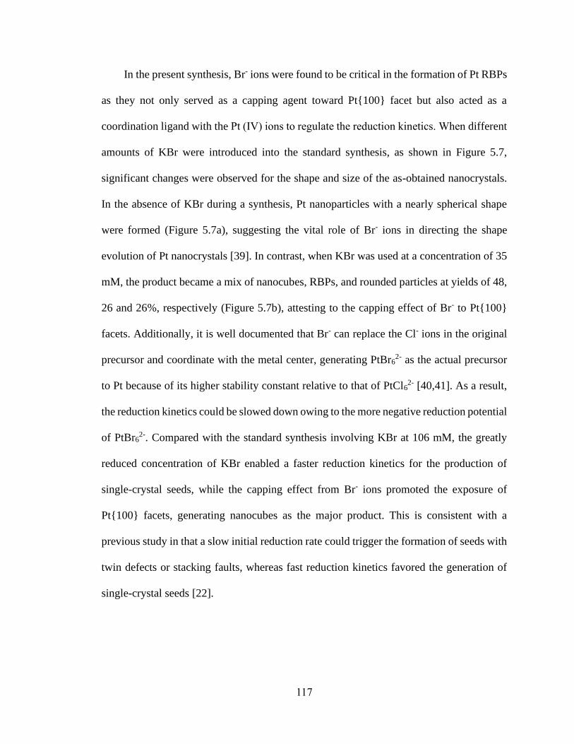
117
In the present synthesis, Br- ions were found to be critical in the formation of Pt RBPs
as they not only served as a capping agent toward Pt{100} facet but also acted as a
coordination ligand with the Pt (Ⅳ) ions to regulate the reduction kinetics. When different
amounts of KBr were introduced into the standard synthesis, as shown in Figure 5.7,
significant changes were observed for the shape and size of the as-obtained nanocrystals.
In the absence of KBr during a synthesis, Pt nanoparticles with a nearly spherical shape
were formed (Figure 5.7a), suggesting the vital role of Br- ions in directing the shape
evolution of Pt nanocrystals [39]. In contrast, when KBr was used at a concentration of 35
mM, the product became a mix of nanocubes, RBPs, and rounded particles at yields of 48,
26 and 26%, respectively (Figure 5.7b), attesting to the capping effect of Br- to Pt{100}
facets. Additionally, it is well documented that Br- can replace the Cl- ions in the original
precursor and coordinate with the metal center, generating PtBr62- as the actual precursor
to Pt because of its higher stability constant relative to that of PtCl62- [40,41]. As a result,
the reduction kinetics could be slowed down owing to the more negative reduction potential
of PtBr62-. Compared with the standard synthesis involving KBr at 106 mM, the greatly
reduced concentration of KBr enabled a faster reduction kinetics for the production of
single-crystal seeds, while the capping effect from Br- ions promoted the exposure of
Pt{100} facets, generating nanocubes as the major product. This is consistent with a
previous study in that a slow initial reduction rate could trigger the formation of seeds with
twin defects or stacking faults, whereas fast reduction kinetics favored the generation of
single-crystal seeds [22].

118
Figure 5.7. TEM images of Pt nanocrystals obtained using the standard protocol except
for changing the concentration of KBr from 109 mM in the standard synthesis to (a) 0, (b)
35, (c) 159, and (d) 212 mM, respectively. With the increase of KBr concentration, the
products changed from single crystal to twinned structures and finally irregular particles,
implying deceleration of the reduction kinetics.
With the further increase in KBr concentration to 159 and 212 mM, more
nanoparticles with an irregular shape were observed in the products (Figure 5.7, c and d),
in addition to nanocubes and RBPs. The occurrence of irregular particles can be attributed
to the substantially slower reduction kinetics, generating seeds with different internal
structures. Moreover, it is clearly observed that the size of the as-obtained nanocrystals
became larger as the concentration of KBr was increased, suggesting that the reduction rate
was slowed down and thus fewer seeds were formed in the nucleation step. Since the

119
amount of precursor fed into the synthesis was fixed, more precursors would be allocated
to each seed in the growth step, leading to an increase in size for the nanocrystals. Taken
together, the use of KBr at a proper concentration is vital to the preparation of Pt RBPs,
because of the dual roles of Br- ions in capping Pt{100} facets and regulating the reduction
kinetics.
In addition to the concentration of KBr, the temperature used for triggering the
nucleation should have a profound impact on the internal structures of the seeds and the
resultant nanocrystals by affecting the initial reduction rate of a synthesis. To gain deeper
insights into the formation of Pt RBPs, I conducted experiments by following the standard
procedure while varying the temperature for the nucleation step. When the nucleation was
allowed to proceed at a higher temperature of 175 ℃, the purity of RBPs dropped to 59%
and more nanocubes were observed in the products (Figure 5.8a). The lower purity of RBPs
can be ascribed to the accelerated reduction kinetics at the elevated temperature, which
resulted in the formation of single-crystals seeds and thus the generation of nanocubes. In
comparison, lowering the temperature for nucleation to 155 ℃ led to a slower initial
reduction rate. Consequently, less cubes were observed in the products, while multiply-
twinned nanocrystals appeared, as indicated by the red arrows (Figure 5.8b). The main
product became plate-like nanocrystals, which were actually RBP with truncated corners,
likely due to the overgrowth of RBPs in the presence of excess precursor. Owing to the
slower reduction rate at 155 ℃, less seeds could be produced during nucleation, and thus
more precursors would be available to each seed for growth. After the seeds evolved into
RBPs, the remaining precursor may lead to further deposition of atoms on the nanocrystals,
which should selectively start from the twin defects because of the relatively high surface

120
energy of these sites. However, the slow production of atoms by surface reduction, as well
as the sufficient adatom surface diffusion at 120 ℃, allowed the deposited atoms to migrate
from twin defects to the edges and side faces of the nanocrystals, resulting in the formation
of truncated RBPs. This is consistent with the result of a prior study, in which truncated Pd
RBPs were generated via seeded growth from RBPs in the presence of additional precursor
[7]. Therefore, the temperature for triggering nucleation should be optimized in order to
obtain a proper amount of singly-twinned seeds for the generation of RBPs.
Figure 5.8. TEM images of Pt nanocrystals prepared by following the standard protocol
except that the temperatures used for nucleation/growth were changed from 165/120 ℃ to
(a) 175/120 ℃, (b) 155/120 ℃, (c) 165/140 ℃, and (d) 165/100 ℃, respectively. The red
arrows indicate the multiply-twinned structures.

121
Since the growth pattern of seeds also depends on the reduction kinetics, the influence
of the temperature for the growth step on the resultant nanocrystals was investigated as
well. As shown in Figure 5.8c, when the growth was carried out at an elevated temperature
of 140 ℃, a portion of the nanocrystals with smaller sizes were observed in the products,
implying the occurrence of additional nucleation events during the growth step. At 140 ℃,
a temperature high enough to overcome the activation energy barrier for solution reduction,
homogeneous nucleation was enabled, generating additional seeds and thus smaller
nanocrystals due to their shorter duration of growth. Meanwhile, the newly-formed seeds
could take different internal structures for the formation of nanocrystals with irregular
shapes, resulting in degradation of product quality. In comparison, at a low temperature of
100 ℃, it was difficult to initiate growth on the seeds via surface reduction owing to the
greatly decelerated reduction kinetics (Figure 5.8d). As a result of insufficient growth, the
as-obtained nanocrystals exhibited a rounded shape and small sizes, instead of evolving
into Pt RBPs. Taken together, it is critical to choose a proper temperature to suppress
homogeneous nucleation and formation of undesired seeds during growth while enabling
reduction of the precursor on the surface of the seeds for their growth into RBPs.
5.3 Conclusion
In summary, I have developed a facile method for the preparation of Pt RBPs by
separating the nucleation and growth of a synthesis into two steps. Particularly, a
continuous flow reactor was utilized to control the nucleation step by thermally triggering
the reduction of a precursor in the solution phase at a high temperature and thus enabling
homogeneous nucleation to obtain singly-twinned seeds. The subsequent growth at a lower
temperature preserved the singly-twinned seeds from oxidative etching for their slow

122
evolution into RBPs while suppressing additional nucleation of unwanted seeds and thus
ensuring RBPs as the major product. The Br- ions introduced into the synthesis played vital
roles in the formation of Pt RBPs by acting as a capping agent to promote the exposure of
{100} facets and a ligand to regulate the reduction kinetics through coordination with Pt(Ⅳ)
ions. It was revealed that the pair of temperatures for the nucleation and growth steps have
profound impacts on the formation of Pt RBPs by affecting the internal structure and
growth pattern of the seeds, respectively. By separating nucleation from growth and
controlling nucleation in a tubular flow reactor, each step could be conducted under optimal
conditions for the generation of Pt RBPs. This work offers not only a facile route to the
production of Pt RBPs but also a new approach that we could leverage for tightly
controlling nucleation and growth for the synthesis of nanocrystals with desired shapes and
structures.
5.4 Experimental Section
Chemicals and Materials. Sodium hexachloroplatinate(Ⅳ) hexahydrate
(Na2PtCl6•6H2O, 98%), potassium bromide (KBr, 99.0%), and poly(vinyl pyrrolidone)
(PVP, Mw ≈ 55,000) were all obtained from Sigma-Aldrich. Ethylene glycol (EG, ≥ 99.0%)
was purchased from J. T. Baker. All chemicals were used as received. Deionized water
with a resistivity of 18.2 MΩ·cm at room temperature was used for the experiments.
Synthesis of Pt RBPs by Controlling Nucleation in a Continuous Flow Reactor.
In a standard protocol, 10 mg of Na2PtCl6•6H2O was dissolved in 2 mL of EG under
sonication. To verify whether sonication induced any reduction and nucleation in the
solution, the precursor solution was centrifuged at 100,000 rpm for 1 h. No solid precipitate
was observed and the concentration of the Pt(Ⅳ) ions remaining in the “supernatant” did

123
not change before and after sonication, as confirmed by ICP-MS. Meanwhile, 3 mL of EG
solution containing 50 mg of PVP and 63 mg of KBr was heated to 100 ℃ for 7 min to
fully dissolve the chemicals, followed by natural cooling to room temperature. The two
solutions were then mixed under magnetic stirring for 15 min to obtain a homogeneous
reaction mixture. As shown in Figure 5.1, a PTFE tube with an inner diameter of 0.8 mm
was utilized to trigger the nucleation process by immersing one segment of the tube in an
oil bath held at 165 ℃. Specifically, the reaction solution was continuously introduced into
the preheated PTFE tube using a syringe pump at a flow rate of 0.1 mL/min to initiate the
reduction of the Pt(Ⅳ) precursor and thus nucleation at the elevated temperature. Since the
retention time of the solution in the flow reactor is determined by both the length of the
segment being heated and the flow rate, the duration for nucleation could be controlled at
330 s by subjecting 204 cm of the tube to heating. After passing through the oil bath, the
solution containing the just-formed seeds was collected by a test tube held in an ice bath to
quickly quench the reaction and thus suppress the nucleation of additional, undesired seeds.
The solution was then transferred into a 20-mL glass vial and bubbled with argon for 20
min to expel the oxygen from the vial and thereby suppress oxidative etching of the singly-
twinned seeds during growth. Finally, the tightly capped vial was heated in an oil bath held
at 120 ℃ for 48 h for the seeds to grow into Pt RBPs. After the synthesis, acetone was
added into the reaction solution at a volume ratio of 7 to 3 and the mixture was centrifuged
at 17,500 rpm for 15 min to collect the solid products. The as-obtained products were then
washed twice with water and redispersed in water for further characterization.
Characterizations. The TEM images were acquired on a Hitachi HT7700
microscope operated at 120 kV. The aqueous suspensions of the nanocrystals were drop-

124
cast on carbon-coated copper grids and dried under ambient conditions prior to TEM
analysis. The HAADF-STEM images were taken with a Hitachi HT2700 aberration-
corrected STEM operated at 200 kV. To remove the remaining surfactants, the sample was
washed 10 times with water and then treated in a Hitachi Zone cleaner for 30 min before
imaging. Analysis of the metal content was performed with an ICP mass spectrometer
(Perkin-Elmer, NexION 300Q).
5.5 Notes to Chapter 5
Part of this Chapter is adapted from the paper “Synthesis of Pt Right Bipyramids by
Separating and Controlling the Nucleation Step in a Continuous Flow System” submitted
to Chemistry-A European Journal.
5.6 References
[1] Dreaden, E. C.; Alkilany, A. M.; Huang, X.; Murphy, C. J.; El-Sayed, M. A. Chem.
Soc. Rev. 2012, 41, 2740−2779.
[2] Navlani-García, M.; Salinas-Torres, D.; Mori, K.; Kuwahara, Y.; Yamashita, H.
Catal. Surv. Asia 2019, 23, 127−148.
[3] Zada, A.; Muhammad, P.; Ahmad, W.; Hussain, Z.; Ali, S.; Khan, M.; Khan, Q.;
Maqbool, M. Adv. Funct. Mater. 2020, 30, 1906744.
[4] Shi, Y.; Lyu, Z.; Zhao, M.; Chen, R.; Nguyen, Q. N.; Xia, Y. Chem. Rev. 2021, 121,
649−735.
[5] Wiley, B. J.; Xiong, Y.; Li, Z.-Y.; Yin, Y.; Xia, Y. Nano Lett. 2006, 6, 765−768.
[6] Ruan, L.; Chiu, C.-Y.; Li, Y.; Huang, Y. Nano Lett. 2011, 11, 3040−3046.
[7] Xia, X.; Choi, S.-I.; Herron, J. A.; Lu, N.; Scaranto, J.; Peng, H.-C.; Wang, J.;
Mavrikakis, M.; Kim, M. J.; Xia, Y. J. Am. Chem. Soc. 2013, 135, 15706−15709.
[8] Lyu, Z.; Xie, M.; Gilroy, K. D.; Hood, Z. D.; Zhao, M.; Zhou, S.; Liu, J.; Xia, Y.
Chem. Mater. 2018, 30, 6469−6477.

125
[9] Ringe, E.; Zhang, J.; Langille, M. R.; Mirkin, C. A.; Marks, L. D.; Van Duyne, R.
P. Nanotechnology 2012, 23, 444005.
[10] Lu, N.; Chen, W.; Fang, G.; Chen, B.; Yang, K.; Yang, Y.; Wang, Z.; Huang, S.;
Li, Y. Chem. Mater. 2014, 26, 2453−2459.
[11] Tavakkoli Yaraki, M.; Daqiqeh Rezaei, S.; Middha, E.; Tan, Y. N. Part. Part. Syst.
Charact. 2020, 37, 2000027.
[12] Zhou, S.; Zhao, M.; Yang, T.-H.; Xia, Y. Mater. Today 2019, 22, 108−131.
[13] Wang, H.; Zhou, S.; Gilroy, K. D.; Cai, Z.; Xia, Y. Nano Today 2017, 15, 121−144.
[14] Elechiguerra, J. L.; Reyes-Gasga, J.; Yacaman, M. J. J. Mater. Chem. 2006, 16,
3906−3919.
[15] Wang, Y.-J.; Long, W.; Wang, L.; Yuan, R.; Ignaszak, A.; Fang, B.; Wilkinson, D.
P. Energy Environ. Sci. 2018, 11, 258−275.
[16] Sui, S.; Wang, X.; Zhou, X.; Su, Y.; Riffat, S.; Liu, C.-j. J. Mater. Chem. A 2017,
5, 1808−1825.
[17] Miyake, M.; Miyabayashi, K. Catal. Surv. Asia 2012, 16, 1−13.
[18] Porter, N. S.; Wu, H.; Quan, Z.; Fang, J. Acc. Chem. Res. 2013, 46, 1867−1877.
[19] Kibey, S.; Liu, J. B.; Johnson, D. D.; Sehitoglu, H. Acta Mater. 2007, 55,
6843−6851.
[20] Xia, Y.; Xiong, Y.; Lim, B.; Skrabalak, S. E. Angew. Chem. Int. Ed. 2009, 48,
60−103.
[21] Tao, A. R.; Habas, S.; Yang, P. Small 2008, 4, 310−325.
[22] Wang, Y.; Peng, H.-C.; Liu, J.; Huang, C. Z.; Xia, Y. Nano Lett. 2015, 15,
1445−1450.
[23] Long, R.; Zhou, S.; Wiley, B. J.; Xiong, Y. Chem. Soc. Rev. 2014, 43, 6288−6310.
[24] Zheng, Y.; Zeng, J.; Ruditskiy, A.; Liu, M.; Xia, Y. Chem. Mater. 2014, 26, 22−33.
[25] Janssen, A.; Shi, Y.; Xia, Y. Chem. Eur. J. 2020, 26, 13890−13895.
[26] Pan, J.; El-Ballouli, A. a. O.; Rollny, L.; Voznyy, O.; Burlakov, V. M.; Goriely, A.;
Sargent, E. H.; Bakr, O. M. ACS Nano 2013, 7, 10158−10166.
[27] Kim, K.-J.; Oleksak, R. P.; Hostetler, E. B.; Peterson, D. A.; Chandran, P.; Schut,
D. M.; Paul, B. K.; Herman, G. S.; Chang, C.-H. Cryst. Growth Des. 2014, 14,
5349−5355.

126
[28] Chen, R.; Lyu, Z.; Shi, Y.; Xia, Y. Chem. Mater. 2021, 33, 3791−3801.
[29] Niu, G.; Ruditskiy, A.; Vara, M.; Xia, Y. Chem. Soc. Rev. 2015, 44, 5806−5820.
[30] Erdem, E. Y.; Cheng, J. C.; Doyle, F. M.; Pisano, A. P. Small 2014, 10, 1076−1080.
[31] Sui, J.; Yan, J.; Liu, D.; Wang, K.; Luo, G. Small 2020, 16, 1902828.
[32] Roberts, E. J.; Karadaghi, L. R.; Wang, L.; Malmstadt, N.; Brutchey, R. L. ACS
Appl. Mater. Interfaces 2019, 11, 27479−27502.
[33] Kunal, P.; Roberts, E. J.; Riche, C. T.; Jarvis, K.; Malmstadt, N.; Brutchey, R. L.;
Humphrey, S. M. Chem. Mater. 2017, 29, 4341−4350.
[34] Song, H.; Tice, J. D.; Ismagilov, R. F. Angew. Chem. Int. Ed. 2003, 42, 767−772.
[35] McEachran, M.; Kitaev, V. Chem. Commun. 2008, 5737−5739.
[36] Watzky, M. A.; Finke, R. G. J. Am. Chem. Soc. 1997, 119, 10382−10400.
[37] Yang, T.-H.; Peng, H.-C.; Zhou, S.; Lee, C.-T.; Bao, S.; Lee, Y.-H.; Wu, J.-M.; Xia,
Y. Nano Lett. 2017, 17, 334−340.
[38] Yang, T.-H.; Zhou, S.; Gilroy, K. D.; Figueroa-Cosme, L.; Lee, Y.-H.; Wu, J.-M.;
Xia, Y. Proc. Natl. Acad. Sci. U. S. A. 2017, 114, 13619.
[39] Yang, T.-H.; Shi, Y.; Janssen, A.; Xia, Y. Angew. Chem. Int. Ed. 2020, 59,
15378−15401.
[40] Xia, X.; Wang, Y.; Ruditskiy, A.; Xia, Y. Adv. Mater. 2013, 25, 6313−6333.
[41] Li, H.-H.; Ma, S.-Y.; Fu, Q.-Q.; Liu, X.-J.; Wu, L.; Yu, S.-H. J. Am. Chem. Soc.
2015, 137, 7862−7868.

127
CHAPTER 6
CONCLUSIONS AND FUTURE DIRECTIONS
6.1 Conclusions
This dissertation presents several strategies for controlling the colloidal synthesis of
Pd and Pt nanocrystals with well-defined shapes, improved purity and uniformity, together
with the evaluation of their performances in electrocatalytic applications. The first two
projects focused on developing synthetic protocols for Pt nanocrystals with reduced
symmetry relative to their cubic lattice and uncovering the mechanisms for anisotropic
growth. The Pt nanocrystals exhibited enhanced catalytic activity toward ORR and the
production can be easily scaled up using a continuous flow reactor. The other two projects
further explored the utilization of flow reactor in controlling the nucleation step of a
synthesis and decoupling growth from nucleation for the production of noble-metal
nanocrystals with high uniformity and purity.
I first developed a facile route to Pt nanobars lower in symmetry relative to its cubic
lattice and unveiled the mechanism responsible for symmetry breaking and anisotropic
growth. By simply heating the mixture of a Pt(IV) precursor, PVP, and DMF at 160 °C, Pt
nanobars with a small size of 8 nm in length (measured from the longer edge seen in the
TEM image) and an aspect ratio tunable up to 2.1 could be obtained. The involvement of
DMF was found to be critical to the synthesis because of its multiple roles as a solvent, a
reductant, and most importantly, a precursor to the actual capping agent. The
decomposition of DMF produced CO in situ, which could selectively stabilize Pt{100}
facets and thus promote the generation of Pt nanobars. By varying the amount of precursor

128
involved in the synthesis and the concentration of PVP that acted as both a stabilizer and a
co-reductant, the aspect ratio and size of the Pt nanobars could be readily tuned. Following
mechanistic study revealed that the anisotropic growth could be ascribed to both particle
coalescence in the early stage of the synthesis and localized oxidative etching followed by
preferential growth, giving rise to Pt nanobars with reduced symmetry. This work offers
not only a simple route to the preparation of Pt nanobars, but also deeper insights into
symmetry reduction and anisotropic growth of noble-metal nanocrystals.
With the knowledge of symmetry breaking and anisotropic growth, I then
demonstrated the use of a continuous flow reactor for the scalable production of Pt
multipods with an anisotropic morphology, small size, and enhanced activity toward ORR.
The facile protocol only involved Pt(acac)2 as a precursor and oleylamine as a solvent,
surfactant, and temperature-dependent reductant. By pumping the reaction solution into a
tubular flow reactor with one portion subjected to heating at 180 °C, Pt multipods were
generated at a higher throughput of 17 mg of Pt per hour with a tighter control over the
product quality, compared with the conventional batch-based synthesis. By monitoring the
shape evolution of the nanocrystals, it was revealed that the anisotropic growth of Pt
multipods could be attributed to both fast autocatalytic surface growth and attachment of
small particles. Owing to its open, branched structure and high specific surface area, Pt
multipods exhibited enhanced catalytic activity toward ORR in comparison with the
commercial Pt/C catalyst. This project holds promise for the mass production of Pt
nanocrystals to be used as effective ORR catalysts in PEMFCs.
I further explored the additional opportunities offered by flow reactor in controlling
the subtle but vital nucleation step of a colloidal synthesis and demonstrated a strategy for

129
decoupling growth from nucleation to improve the purity and uniformity of noble-metal
nanocrystals. Taking Pd nanocubes as an example, I redesigned the experimental setup for
the separation of nucleation and growth processes while manipulating the reduction
pathway of the precursor. Specifically, the reaction solution was pumped into a tubular
reactor subjected to heating to thermally trigger the reduction of precursor in solution phase
and therefore a single burst of homogeneous nucleation over a very short period of time.
The just-formed seeds were then allowed to grow slowly at room temperature via surface
reduction, producing pure and uniform Pd nanocubes. By quantitatively analyzing the
reduction kinetics and characterizing the intermediates obtained at different time points of
the synthesis, it was confirmed that no additional nucleation of unwanted seeds occurred
during growth, contributing to the high purity and uniformity of the product. Further
investigation indicated that both the temperature and duration for nucleation had profound
impacts on the quality of the seeds and thus the resultant nanocrystals. This methodology
was also extended to the preparation of highly pure and uniform sub-5 nm Pt nanocubes,
demonstrating the generality of this strategy for the synthesis of various noble-metal
nanocrystals.
The strategy for separating nucleation from growth and for controlling the nucleation
step in a continuous flow system was then extended to the synthesis of Pt RBPs taking a
singly-twinned structure. Specifically, homogeneous nucleation was thermally initiated by
introducing the reaction solution into a tubular flow reactor held at an elevated temperature
to generate singly-twinned seeds. At a lower temperature, the singly-twinned seeds were
protected from oxidative etching and slowly grew into RBPs while additional nucleation
of undesired seeds were largely suppressed to ensure RBPs as the main product. The Br-
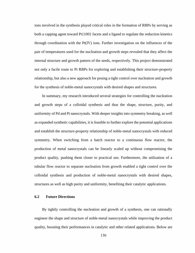
130
ions involved in the synthesis played critical roles in the formation of RBPs by serving as
both a capping agent toward Pt{100} facets and a ligand to regulate the reduction kinetics
through coordination with the Pt(Ⅳ) ions. Further investigation on the influences of the
pair of temperatures used for the nucleation and growth steps revealed that they affect the
internal structure and growth pattern of the seeds, respectively. This project demonstrated
not only a facile route to Pt RBPs for exploring and establishing their structure-property
relationship, but also a new approach for posing a tight control over nucleation and growth
for the synthesis of noble-metal nanocrystals with desired shapes and structures.
In summary, my research introduced several strategies for controlling the nucleation
and growth steps of a colloidal synthesis and thus the shape, structure, purity, and
uniformity of Pd and Pt nanocrystals. With deeper insights into symmetry breaking, as well
as expanded synthetic capabilities, it is feasible to further explore the potential applications
and establish the structure-property relationship of noble-metal nanocrystals with reduced
symmetry. When switching from a batch reactor to a continuous flow reactor, the
production of metal nanocrystals can be linearly scaled up without compromising the
product quality, pushing them closer to practical use. Furthermore, the utilization of a
tubular flow reactor to separate nucleation from growth enabled a tight control over the
colloidal synthesis and production of noble-metal nanocrystals with desired shapes,
structures as well as high purity and uniformity, benefiting their catalytic applications.
6.2 Future Directions
By tightly controlling the nucleation and growth of a synthesis, one can rationally
engineer the shape and structure of noble-metal nanocrystals while improving the product
quality, boosting their performances in catalytic and other related applications. Below are

131
some directions that future endeavors should be devoted to, in an effort to achieve
controllable and predictable synthesis of metal nanocrystals and help push them closer to
practical use.
1. Although a variety of strategies have been proposed for breaking the symmetry
constraint from metal lattice and inducing anisotropic growth, the underlying mechanism
and exact growth pathway still need further investigation. Currently, our understanding of
symmetry breaking during nanocrystals growth is primarily based on the inspection of
products obtained under different reaction conditions [1], while direct observation of the
growth process is lacked, querying the speculated mechanism. In this case, advanced
characterization tools capable of monitoring nanocrystals growth with atomic resolution
over ultrashort timescales, such as in situ HRTEM and synchrotron diffraction, are needed
for scrutinizing the underlying mechanism. Additionally, as a complementary approach to
experiment study, computational simulation can also be leveraged to probe the mechanistic
details involved in the growth process while rationalizing the experimental observation.
For example, in a recent study, the growth of an Au truncated decahedron into penta-
twinned nanorod was investigated by both liquid-cell TEM and density functional theory
(DFT) simulations, validating the synergistic roles of strain and surface energy in directing
anisotropic growth [2]. Future endeavors should focus on a combination of in situ
experimental observation and computational simulation to unveil the mechanisms of
symmetry reduction and anisotropic growth, which will greatly deeper our mechanistic
understanding of the growth process while expanding our synthetic capabilities.
2. The synthetic strategy of separating nucleation and growth can be extended to the
preparation of other types of noble-metal nanocrystals to improve their uniformity in terms

132
of shape and size, in an effort to enhance their performances in catalytic applications. As
an essential issue in the long-term use of nanocatalysts, sintering of nanocrystals under
harsh chemical and electrochemical environments usually results in the loss of their
specific surface area and thus mass activity [3-5]. Therefore, close attention should be paid
to the measures of improving the resistance of nanocrystals against sintering for retaining
their activity over a long period of time. Previous study has demonstrated that Pt
nanoclusters with a uniform size distribution were highly resistant to sintering because
Ostwald ripening was substantially suppressed [6]. By decoupling nucleation from growth
in a colloidal synthesis, it is expected that the as-obtained nanocrystals will have a narrow
size distribution and thus exhibit higher durability under reaction conditions as a result of
the mitigation of sintering. It should be pointed out that this strategy can be extended to the
preparation of nanocrystals made of various metals, but the synthetic protocols should be
modified separately for each metal owing to the differences in their intrinsic properties.
3. In addition to improving the purity and uniformity of nanocrystals, the tubular flow
reactor opens up new opportunities for the controllable and predictable synthesis of
nanocrystals with desired size and quantity. In a recent study, a kinetic descriptor, (growth-
to-nucleation rate ratio)1/3, was proposed, based on in situ small angle X-ray scattering
(SAXS) analysis and kinetic modeling, for predicting the size of resultant nanoparticles [7].
Nevertheless, the synthesis of nanocrystals with well-controlled sizes may be achieved
simply through the utilization of a tubular flow reactor to tightly manage the experimental
conditions and durations for the nucleation process. Specifically, by analyzing the
reduction of precursor concentration and the size of seeds obtained after a certain period of
nucleation, one can establish the correlation between the nucleation time and the quantity

133
of seeds generated. With the amount of precursor added into the synthesis known, it is
feasible to estimate the quantity as well as size of the final product obtained after a growth
only stage. In turn, based on such quantitative analysis, one can synthesize nanocrystals
with desired size and quantity in a controllable and predictable manner with the duration
of nucleation tightly controlled in a flow reactor. Different from the conventional synthesis,
in which tuning the quantity and size of the resultant nanocrystals largely relies on
empirical knowledge in adjusting the experimental parameters [8,9], this method enables
quantitative depiction and prediction of the outcome of a synthesis. As such, our control
over the production of noble-metal nanocrystals can be further advanced, paving the way
for their use in practical applications.
4. Despite the progress in controlling the synthesis of noble-metal nanocrystals and
our understanding of nanocrystal growth, it remains a grand challenge to uncover the
mechanistic details involved in the very fast while extremely vital nucleation process. In
addition to tightly controlling nucleation, the continuous flow reactor can be further
explored as a powerful platform for probing the underlying mechanism. Specifically, the
fast initiation and quenching of reaction in a continuous flow system makes it possible to
collect and characterize intermediates formed after several seconds into the reaction,
providing detailed information on the synthesis over short timescales. Additionally, the
continuous flow reactor can be integrated with advanced characterization techniques, such
as X-ray absorption fine structure (XAFS) spectroscopy [10], fluorescence detector [11-
14], and SAXS setup [15], for online detection and analysis of the pathways and kinetics
of nucleation and growth processes. Although a number of studies have reported the use of
such techniques to investigate the synthetic process of quantum dots and perovskite

134
nanocrystals [11-14], only limited success was achieved in studying colloidal noble-metal
nanocrystals [10,15]. In a previous study, the combination of a continuous flow reactor
with XAFS enabled in situ monitoring of the nucleation of Au nanocrystals, revealing that
partial reduction of the precursor occurred in the early stage of nucleation, followed by
formation of Cl3-Au-AuCl3
- dimers and then larger Au clusters [10]. This result
significantly differed from the homogeneous nucleation process described in the LaMer
model, offering new insights into the nonclassical nucleation mechanism. Through the
integration of continuous flow reactor with online characterization tools, one can probe the
mechanistic details involved in nucleation as well as growth process, pushing forward our
mechanistic understanding of colloidal synthesis.
In addition to the challenges and opportunities listed above, the continuous flow
system is worth of further exploration for the mass production of various noble-metal
nanocrystals in a well-controlled manner. For example, multiple function units can be
incorporated sequentially into the system, allowing the completion of multi-step synthesis
and thus generation of nanocrystals with a broader range of complex structures and
compositions [16]. Besides, to achieve mass production of nanocrystals at an industry
relevant scale, it is essential to ensure the continuous and steady introduction of reagents
into the flow system. However, only a small amount of reagent can be held in the syringe
we currently used in the experimental study, requiring manually reloading during the
synthesis. Therefore, efforts should be devoted to the design and construction of a system
capable of introducing reagents continuously and automatically. Moreover, attention
should be paid to the possible fouling of the inner wall of the flow reactor [17,18] as well
as generation of gases and thus disruption of the flow stream in some syntheses [18,19],

135
achieving a tighter control over the production of noble-metal nanocrystals in the
continuous flow system.
6.3 Notes to Chapter 6
Part of this Chapter is adapted from the articles “A Simple Route to the Synthesis of
Pt Nanobars and the Mechanistic Understanding of Symmetry Reduction” published in
Chemistry-A European Journal [20], “Continuous and Scalable Synthesis of Pt Multipods
with Enhanced Electrocatalytic Activity toward the Oxygen Reduction Reaction”
published in ChemNanoMat [21], “Improving the Purity and Uniformity of Pd and Pt
Nanocrystals by Decoupling Growth from Nucleation in a Flow Reactor” published in
Chemistry of Materials [22], and “Facile Synthesis of Platinum Right Bipyramids by
Separating and Controlling the Nucleation Step in a Continuous Flow System” submitted
to Chemistry-A European Journal.
6.4 References
[1] Gilroy, K. D.; Peng, H.-C.; Yang, X.; Ruditskiy, A.; Xia, Y. Chem. Commun.
2017, 53, 4530−4541.
[2] Jin, B.; Sushko, M. L.; Liu, Z.; Cao, X.; Jin, C.; Tang, R. J. Phys. Chem. Lett.
2019, 10, 1443−1449.
[3] Shi, Y.; Lyu, Z.; Zhao, M.; Chen, R.; Nguyen, Q. N.; Xia, Y. Chem. Rev. 2021,
121, 649−735.
[4] Dai, Y.; Lu, P.; Cao, Z.; Campbell, C. T.; Xia, Y. Chem. Soc. Rev. 2018, 47,
4314−4331.
[5] DeLaRiva, A. T.; Hansen, T. W.; Challa, S. R.; Datye, A. K. J. Catal. 2013, 308,
291−305.
[6] Wettergren, K.; Schweinberger, F. F.; Deiana, D.; Ridge, C. J.; Crampton, A. S.;
Rötzer, M. D.; Hansen, T. W.; Zhdanov, V. P.; Heiz, U.; Langhammer, C. Nano
Lett. 2014, 14, 5803−5809.

136
[7] Mozaffari, S.; Li, W.; Thompson, C.; Ivanov, S.; Seifert, S.; Lee, B.; Kovarik, L.;
Karim, A. M. Nanoscale 2017, 9, 13772−13785.
[8] Jin, M.; Liu, H.; Zhang, H.; Xie, Z.; Liu, J.; Xia, Y. Nano Res. 2010, 4, 83−91.
[9] Lv, T.; Wang, Y.; Choi, S. I.; Chi, M.; Tao, J.; Pan, L.; Huang, C. Z.; Zhu, Y.;
Xia, Y. ChemSusChem 2013, 6, 1923−1930.
[10] Yao, T.; Sun, Z.; Li, Y.; Pan, Z.; Wei, H.; Xie, Y.; Nomura, M.; Niwa, Y.; Yan,
W.; Wu, Z.; Jiang, Y.; Liu, Q.; Wei, S. J. Am. Chem. Soc. 2010, 132, 7696−7701.
[11] Lignos, I.; Stavrakis, S.; Kilaj, A.; deMello, A. J. Small 2015, 11, 4009−4017.
[12] Lignos, I.; Maceiczyk, R.; deMello, A. J. Acc. Chem. Res. 2017, 50, 1248−1257.
[13] Lignos, I.; Stavrakis, S.; Nedelcu, G.; Protesescu, L.; deMello, A. J.; Kovalenko,
M. V. Nano Lett. 2016, 16, 1869−1877.
[14] Yashina, A.; Lignos, I.; Stavrakis, S.; Choo, J.; deMello, A. J. J. Mater. Chem. C
2016, 4, 6401−6408.
[15] Polte, J.; Erler, R.; Thünemann, A. F.; Sokolov, S.; Ahner, T. T.; Rademann, K.;
Emmerling, F.; Kraehnert, R. ACS Nano 2010, 4, 1076−1082.
[16] Nightingale, A. M.; Phillips, T. W.; Bannock, J. H.; de Mello, J. C. Nat. Commun.
2014, 5, 3777.
[17] Wong, W. K.; Yap, S. K.; Lim, Y. C.; Khan, S. A.; Pelletier, F.; Corbos, E. C.
React. Chem. Eng. 2017, 2, 636−641.
[18] Bannock, J. H.; Krishnadasan, S. H.; Heeney, M.; de Mello, J. C. Mater. Horiz.
2014, 1, 373−378.
[19] Khan, S. A.; Duraiswamy, S. Lab Chip 2012, 12, 1807−1812.
[20] Chen, R.; Nguyen, Q. N.; Zhao, M.; Chen, Z.; Chi, M.; Xia, Y. Chem. Eur. J.
2021. 27, 2760−2766.
[21] Chen, R.; Cao, Z.; Lyu, Z.; Xie, M.; Shi, Y.; Xia, Y. ChemNanoMat 2019, 5,
599–605.
[22] Chen, R.; Lyu, Z.; Shi, Y.; Xia, Y. Chem. Mater. 2021, 33, 3791−3801.