CONTROLLING BOILER SWELL AND SHRINK - Babcock paper boiler.pdf · 1 CONTROLLING BOILER SWELL AND...
5
1 CONTROLLING BOILER SWELL AND SHRINK INTRODUCTION Steam drum level is one of the major contributors of boiler trips and downtime. Affected by a specific phenomenon (swell and shrink) it is difficult to control the drum level optimally. Studies were conducted to determine the best configuration to control steam drum level and how to optimise it. BOILER CIRCULATION In natural circulation boilers the steam drum is used to separate steam from water by scrubbers and other mechanical equipment. Once the steam is separated it flows to the superheated and main steam equipment with the outflow replenished by adding feed water to the drum. Natural circulation within the boiler causes the feed water to flow from the steam drum through the down-comers to the boiler furnace. When the water reaches saturation temperature it flows back to the steam drum due to a change in density, steam and water are again separated in the steam drum and the cycle continues. Figure 1 indicates a basic representation of natural circulation within a boiler circuit. Figure 1 Basic representation of natural boiler circulation SWELL AND SHRINK REACTION Steam flow from the boiler is controlled by the downstream process (e.g. a turbine). A sudden increase or decrease in steam flow changes the pressure in the steam drum and boiler circuit. The change in pressure will cause a change in both the boiling point and density of the water and steam. These combined reactions will cause the level in the steam drum to increase or decrease rapidly. The increase and decrease in the water level caused by the pressure change are commonly referred to as the swell and shrink reactions. The swell and shrink reaction is in the opposite direction to the normal behaviour of the boiler process. Thus, swell and shrink reactions adversely affect the control of steam drum level. If the steam output from the boiler is reduced suddenly, the pressure will increase in the boiler circuit. This increase of pressure will cause the drum level to shrink initially and then increase due to the higher inflow than outflow. The inverse is true when the steam output from the boiler is increased suddenly. Unstable energy input to the boiler can also cause pressure changes that result in the same swell and shrink reactions, making control of the steam drum level extremely difficult. DRUM LEVEL CONTROL CONFIGURATION AND TESTING The objective of the control loop is to maintain the water level at 50% of steam drum capacity. Water in the steam drum must not be allowed to deviate from the specified minimum and maximum trip limits. The trip limit of a boiler is determined during the design of the steam drum. The trip limits is derived from the boiler size, boiler type, scrubbing equipment and position of the down-comer tubes. The steam drum is generally designed as small as possible (due to the high expense of pressure vessel), thus leads to stringent trip limits. If the water increases above the high trip limit, water will carry over into the steam line and superheater systems and if it decreases below the low trip limit, water tubes can run dry and cause damage to the boiler. Drum level, feed water flow and steam flow are the main parameters used in steam drum level control. Combinations are used in conjunction with cascade and feed-forward methods to control the steam drum level with single, two and three element control the most common configurations. A study was conducted to determine the advantage of using two and three element configurations in a steam drum level application. The testing was conducted on two identical 55 t/h boilers connected to a common header which supplies steam at 66 Barg 490°C to a single turbine unit. Boiler 1 was used as the baseline for the testing. The steam drum level configuration on boiler 1 was left on single-element control during the test period and compared to boiler 2 two-element and three-element control configuration. The following section explains control loop configuration and performance testing of the different control methods.
Transcript of CONTROLLING BOILER SWELL AND SHRINK - Babcock paper boiler.pdf · 1 CONTROLLING BOILER SWELL AND...
1
CONTROLLING BOILER SWELL AND SHRINKINTRODUCTION
Steam drum level is one of the major contributors of boiler trips and downtime. Affected by a specific phenomenon (swell and shrink) it is difficult to control the drum level optimally. Studies were conducted to determine the best configuration to control steam drum level and how to optimise it.
BOILER CIRCULATION
In natural circulation boilers the steam drum is used to separate steam from water by scrubbers and other mechanical equipment. Once the steam is separated it flows to the superheated and main steam equipment with the outflow replenished by adding feed water to the drum.
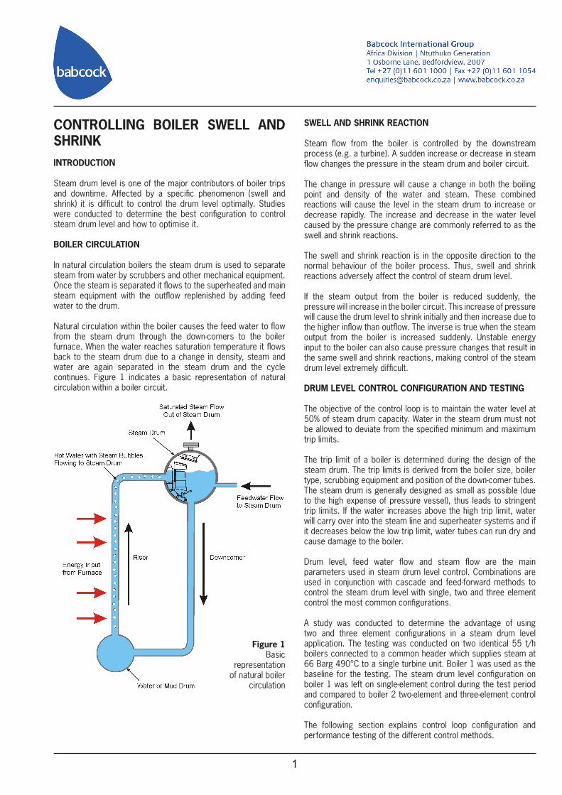
Natural circulation within the boiler causes the feed water to flow from the steam drum through the down-comers to the boiler furnace. When the water reaches saturation temperature it flows back to the steam drum due to a change in density, steam and water are again separated in the steam drum and the cycle continues. Figure 1 indicates a basic representation of natural circulation within a boiler circuit.
Figure 1Basic
representation of natural boiler
circulation
SWELL AND SHRINK REACTION
Steam flow from the boiler is controlled by the downstream process (e.g. a turbine). A sudden increase or decrease in steam flow changes the pressure in the steam drum and boiler circuit.
The change in pressure will cause a change in both the boiling point and density of the water and steam. These combined reactions will cause the level in the steam drum to increase or decrease rapidly. The increase and decrease in the water level caused by the pressure change are commonly referred to as the swell and shrink reactions.
The swell and shrink reaction is in the opposite direction to the normal behaviour of the boiler process. Thus, swell and shrink reactions adversely affect the control of steam drum level.
If the steam output from the boiler is reduced suddenly, the pressure will increase in the boiler circuit. This increase of pressure will cause the drum level to shrink initially and then increase due to the higher inflow than outflow. The inverse is true when the steam output from the boiler is increased suddenly. Unstable energy input to the boiler can also cause pressure changes that result in the same swell and shrink reactions, making control of the steam drum level extremely difficult.
DRUM LEVEL CONTROL CONFIGURATION AND TESTING
The objective of the control loop is to maintain the water level at 50% of steam drum capacity. Water in the steam drum must not be allowed to deviate from the specified minimum and maximum trip limits.
The trip limit of a boiler is determined during the design of the steam drum. The trip limits is derived from the boiler size, boiler type, scrubbing equipment and position of the down-comer tubes. The steam drum is generally designed as small as possible (due to the high expense of pressure vessel), thus leads to stringent trip limits. If the water increases above the high trip limit, water will carry over into the steam line and superheater systems and if it decreases below the low trip limit, water tubes can run dry and cause damage to the boiler.
Drum level, feed water flow and steam flow are the main parameters used in steam drum level control. Combinations are used in conjunction with cascade and feed-forward methods to control the steam drum level with single, two and three element control the most common configurations.
A study was conducted to determine the advantage of using two and three element configurations in a steam drum level application. The testing was conducted on two identical 55 t/h boilers connected to a common header which supplies steam at 66 Barg 490°C to a single turbine unit. Boiler 1 was used as the baseline for the testing. The steam drum level configuration on boiler 1 was left on single-element control during the test period and compared to boiler 2 two-element and three-element control configuration.
The following section explains control loop configuration and performance testing of the different control methods.
2
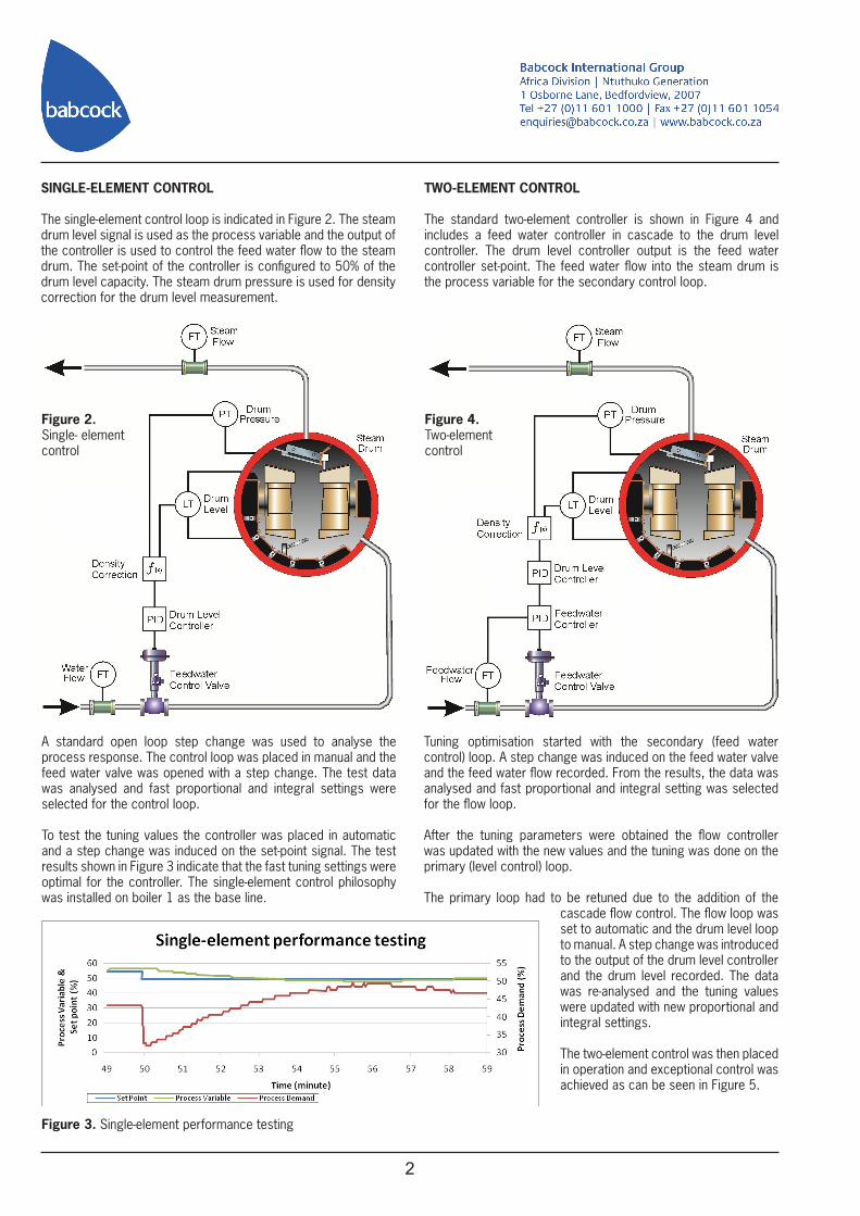
Figure 3. Single-element performance testing
SINGLE-ELEMENT CONTROL
The single-element control loop is indicated in Figure 2. The steam drum level signal is used as the process variable and the output of the controller is used to control the feed water flow to the steam drum. The set-point of the controller is configured to 50% of the drum level capacity. The steam drum pressure is used for density correction for the drum level measurement.
Figure 2.Single- elementcontrol
A standard open loop step change was used to analyse the process response. The control loop was placed in manual and the feed water valve was opened with a step change. The test data was analysed and fast proportional and integral settings were selected for the control loop.
To test the tuning values the controller was placed in automatic and a step change was induced on the set-point signal. The test results shown in Figure 3 indicate that the fast tuning settings were optimal for the controller. The single-element control philosophy was installed on boiler 1 as the base line.
TWO-ELEMENT CONTROL
The standard two-element controller is shown in Figure 4 and includes a feed water controller in cascade to the drum level controller. The drum level controller output is the feed water controller set-point. The feed water flow into the steam drum is the process variable for the secondary control loop.
Tuning optimisation started with the secondary (feed water control) loop. A step change was induced on the feed water valve and the feed water flow recorded. From the results, the data was analysed and fast proportional and integral setting was selected for the flow loop. After the tuning parameters were obtained the flow controller was updated with the new values and the tuning was done on the primary (level control) loop.
The primary loop had to be retuned due to the addition of the cascade flow control. The flow loop was set to automatic and the drum level loop to manual. A step change was introduced to the output of the drum level controller and the drum level recorded. The data was re-analysed and the tuning values were updated with new proportional and integral settings.
The two-element control was then placed in operation and exceptional control was achieved as can be seen in Figure 5.
Figure 4.Two-elementcontrol
3
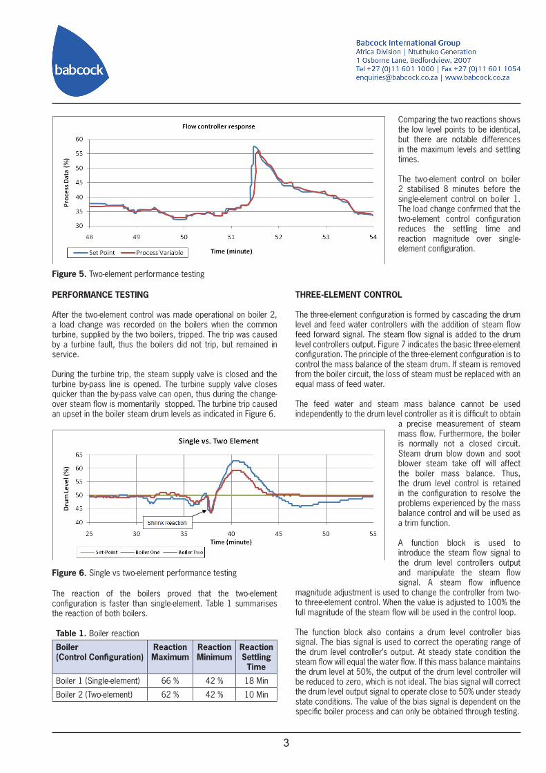
Figure 5. Two-element performance testing
PERFORMANCE TESTING
After the two-element control was made operational on boiler 2, a load change was recorded on the boilers when the common turbine, supplied by the two boilers, tripped. The trip was caused by a turbine fault, thus the boilers did not trip, but remained in service.
During the turbine trip, the steam supply valve is closed and the turbine by-pass line is opened. The turbine supply valve closes quicker than the by-pass valve can open, thus during the change-over steam flow is momentarily stopped. The turbine trip caused an upset in the boiler steam drum levels as indicated in Figure 6.
Figure 6. Single vs two-element performance testing
The reaction of the boilers proved that the two-element configuration is faster than single-element. Table 1 summarises the reaction of both boilers.
Table 1. Boiler reaction
Boiler (Control Configuration)
ReactionMaximum
ReactionMinimum
ReactionSettling Time
Boiler 1 (Single-element) 66 % 42 % 18 Min
Boiler 2 (Two-element) 62 % 42 % 10 Min
Comparing the two reactions shows the low level points to be identical, but there are notable differences in the maximum levels and settling times.
The two-element control on boiler 2 stabilised 8 minutes before the single-element control on boiler 1. The load change confirmed that the two-element control configuration reduces the settling time and reaction magnitude over single- element configuration.
THREE-ELEMENT CONTROL
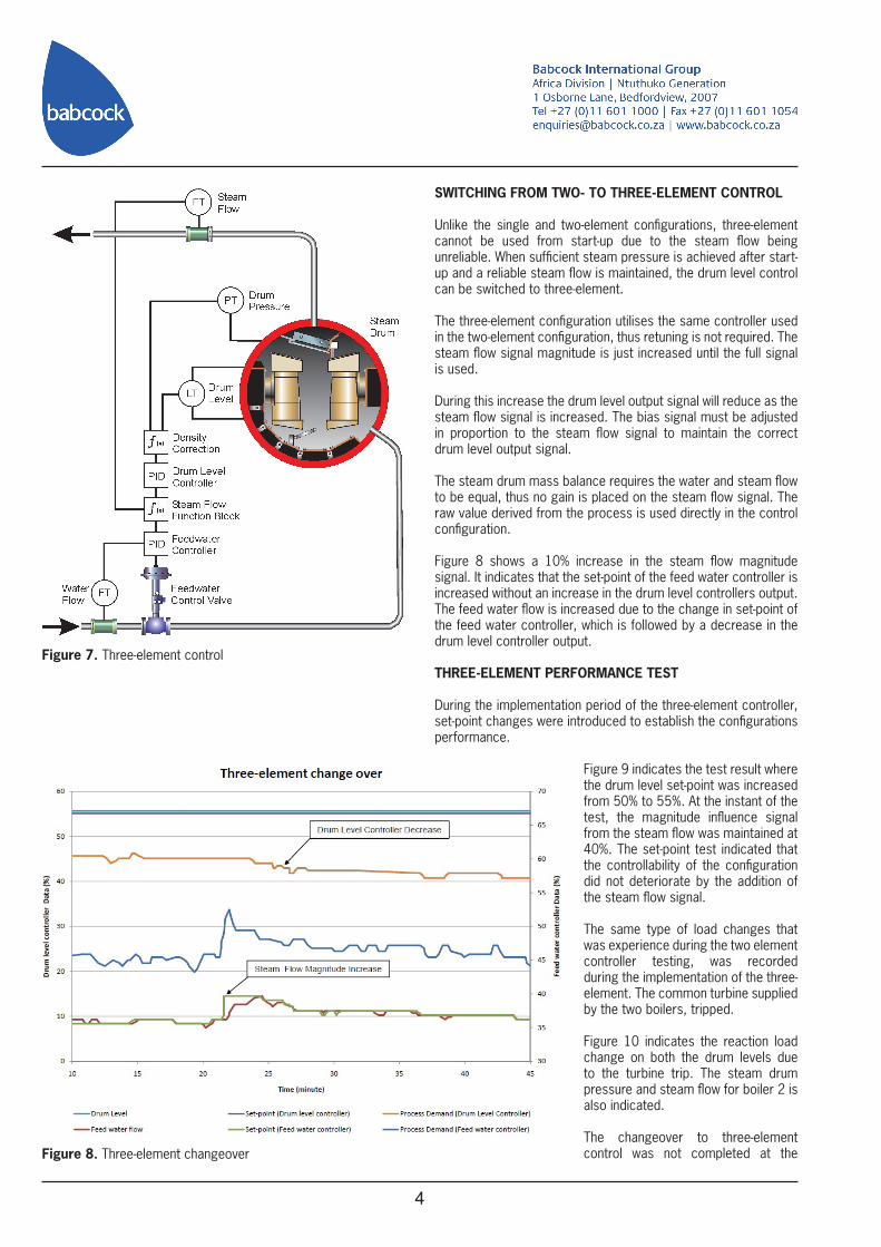
The three-element configuration is formed by cascading the drum level and feed water controllers with the addition of steam flow feed forward signal. The steam flow signal is added to the drum level controllers output. Figure 7 indicates the basic three-element configuration. The principle of the three-element configuration is to control the mass balance of the steam drum. If steam is removed from the boiler circuit, the loss of steam must be replaced with an equal mass of feed water.
The feed water and steam mass balance cannot be used independently to the drum level controller as it is difficult to obtain
a precise measurement of steam mass flow. Furthermore, the boiler is normally not a closed circuit. Steam drum blow down and soot blower steam take off will affect the boiler mass balance. Thus, the drum level control is retained in the configuration to resolve the problems experienced by the mass balance control and will be used as a trim function.
A function block is used to introduce the steam flow signal to the drum level controllers output and manipulate the steam flow signal. A steam flow influence
magnitude adjustment is used to change the controller from two- to three-element control. When the value is adjusted to 100% the full magnitude of the steam flow will be used in the control loop.
The function block also contains a drum level controller bias signal. The bias signal is used to correct the operating range of the drum level controller’s output. At steady state condition the steam flow will equal the water flow. If this mass balance maintains the drum level at 50%, the output of the drum level controller will be reduced to zero, which is not ideal. The bias signal will correct the drum level output signal to operate close to 50% under steady state conditions. The value of the bias signal is dependent on the specific boiler process and can only be obtained through testing.
4
Figure 8. Three-element changeover
Figure 7. Three-element control
SWITCHING FROM TWO- TO THREE-ELEMENT CONTROL
Unlike the single and two-element configurations, three-element cannot be used from start-up due to the steam flow being unreliable. When sufficient steam pressure is achieved after start-up and a reliable steam flow is maintained, the drum level control can be switched to three-element.
The three-element configuration utilises the same controller used in the two-element configuration, thus retuning is not required. The steam flow signal magnitude is just increased until the full signal is used.
During this increase the drum level output signal will reduce as the steam flow signal is increased. The bias signal must be adjusted in proportion to the steam flow signal to maintain the correct drum level output signal.
The steam drum mass balance requires the water and steam flow to be equal, thus no gain is placed on the steam flow signal. The raw value derived from the process is used directly in the control configuration.
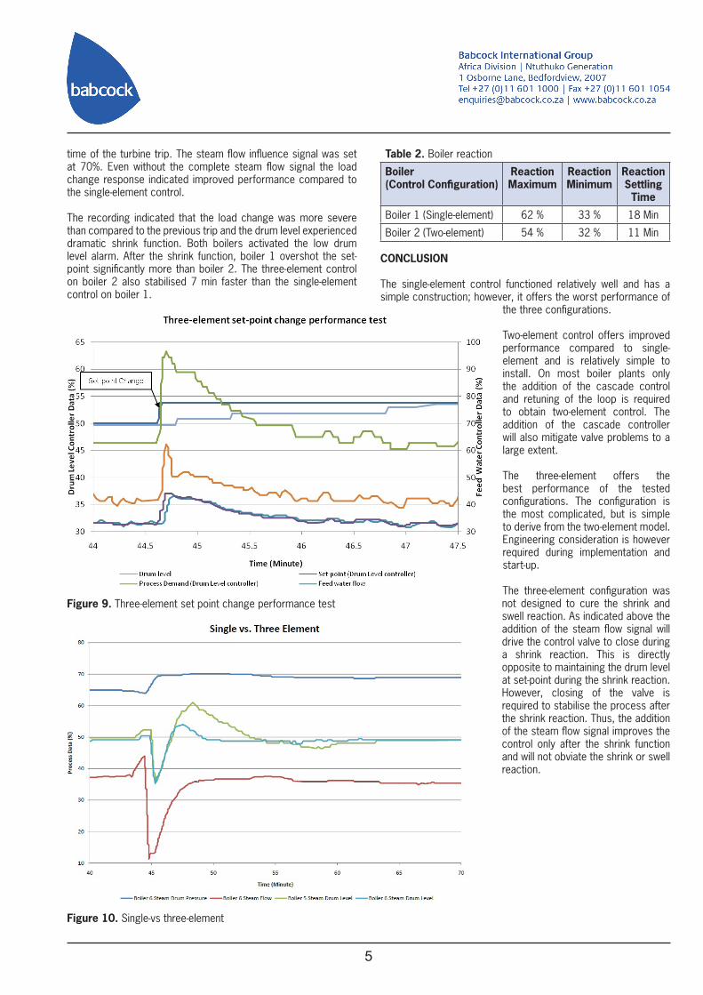
Figure 8 shows a 10% increase in the steam flow magnitude signal. It indicates that the set-point of the feed water controller is increased without an increase in the drum level controllers output. The feed water flow is increased due to the change in set-point of the feed water controller, which is followed by a decrease in the drum level controller output.
THREE-ELEMENT PERFORMANCE TEST
During the implementation period of the three-element controller, set-point changes were introduced to establish the configurations performance.
Figure 9 indicates the test result where the drum level set-point was increased from 50% to 55%. At the instant of the test, the magnitude influence signal from the steam flow was maintained at 40%. The set-point test indicated that the controllability of the configuration did not deteriorate by the addition of the steam flow signal.
The same type of load changes that was experience during the two element controller testing, was recorded during the implementation of the three-element. The common turbine supplied by the two boilers, tripped.
Figure 10 indicates the reaction load change on both the drum levels due to the turbine trip. The steam drum pressure and steam flow for boiler 2 is also indicated.
The changeover to three-element control was not completed at the
5
Figure 9. Three-element set point change performance test
Figure 10. Single-vs three-element
time of the turbine trip. The steam flow influence signal was set at 70%. Even without the complete steam flow signal the load change response indicated improved performance compared to the single-element control.
The recording indicated that the load change was more severe than compared to the previous trip and the drum level experienced dramatic shrink function. Both boilers activated the low drum level alarm. After the shrink function, boiler 1 overshot the set-point significantly more than boiler 2. The three-element control on boiler 2 also stabilised 7 min faster than the single-element control on boiler 1.
Table 2. Boiler reaction
Boiler (Control Configuration)
ReactionMaximum
ReactionMinimum
ReactionSettling Time
Boiler 1 (Single-element) 62 % 33 % 18 Min
Boiler 2 (Two-element) 54 % 32 % 11 Min
CONCLUSION
The single-element control functioned relatively well and has a simple construction; however, it offers the worst performance of
the three configurations.
Two-element control offers improved performance compared to single-element and is relatively simple to install. On most boiler plants only the addition of the cascade control and retuning of the loop is required to obtain two-element control. The addition of the cascade controller will also mitigate valve problems to a large extent.
The three-element offers the best performance of the tested configurations. The configuration is the most complicated, but is simple to derive from the two-element model. Engineering consideration is however required during implementation and start-up.
The three-element configuration was not designed to cure the shrink and swell reaction. As indicated above the addition of the steam flow signal will drive the control valve to close during a shrink reaction. This is directly opposite to maintaining the drum level at set-point during the shrink reaction. However, closing of the valve is required to stabilise the process after the shrink reaction. Thus, the addition of the steam flow signal improves the control only after the shrink function and will not obviate the shrink or swell reaction.