CONTROLLER TUNING FOR NONLINEAR HOPPER PROCESS...
9
Journal of Engineering Science and Technology EURECA 2013 Special Issue August (2014) 59 - 67 © School of Engineering, Taylor’s University 59 CONTROLLER TUNING FOR NONLINEAR HOPPER PROCESS TANK – A REAL TIME ANALYSIS SURESH MANIC KESAVAN*, TVN PADMESH, CHAN WOEI SHYAN CIARG, School of Engineering, Taylor’s University, 47500 Subang Jaya, Selangor DE, Malaysia *Corresponding author: [email protected] Abstract In this work, Proportional + Integral + Derivative (PID) controller design and real time implementation was proposed for a nonlinear hopper tank system in order to solve servo and regulatory problem. Firstly, identification of process transfer function is done through the real time implementation experiment and it is applied to a conventional PID controller. Then tuning methods has been proposed including Cohen-coon (CC), Ziegler & Nichols (ZN), Internal Model Control (IMC) and Tyreus & Luyben (TL). The optimization of tuning parameter is taken up with Integral Square Error (ISE), Integral Absolute Error (IAE) and Integral Time Absolute Error (ITAE). The experimental results show that TL and ZN tuning method are suitable in controlling nonlinear hopper level tank system. Keywords: Nonlinear process, PID controller, Hopper liquid level tank, Tuning method. 1. Introduction In many process industries (petrochemical industries, paper making industries, water treatment industries, etc.) the main issue is to control the level and flow between the tanks. Since many industries involves batch process, it is necessary to control the first process parameter like liquid level or flow, failing to do so may lead to serious shutdown process. So it is necessary to maintain the level of tank at particular set point. Most of the industries deal with nonlinear process tanks such as conical, spherical, hopper type tanks. But the majority of the findings in control theory deal only with the linear system designs. So the control of nonlinear shape of process tank presents a challenging task mainly due to its non-linearity and constantly changing cross section. Hence, the hopper type tank process is taken up for present study.
Transcript of CONTROLLER TUNING FOR NONLINEAR HOPPER PROCESS...

Journal of Engineering Science and Technology EURECA 2013 Special Issue August (2014) 59 - 67 © School of Engineering, Taylor’s University
59
CONTROLLER TUNING FOR NONLINEAR HOPPER PROCESS TANK – A REAL TIME ANALYSIS
SURESH MANIC KESAVAN*, TVN PADMESH, CHAN WOEI SHYAN
CIARG, School of Engineering, Taylor’s University,
47500 Subang Jaya, Selangor DE, Malaysia
*Corresponding author: [email protected]
Abstract
In this work, Proportional + Integral + Derivative (PID) controller design and
real time implementation was proposed for a nonlinear hopper tank system in order to solve servo and regulatory problem. Firstly, identification of process
transfer function is done through the real time implementation experiment and it
is applied to a conventional PID controller. Then tuning methods has been
proposed including Cohen-coon (CC), Ziegler & Nichols (ZN), Internal Model
Control (IMC) and Tyreus & Luyben (TL). The optimization of tuning
parameter is taken up with Integral Square Error (ISE), Integral Absolute Error (IAE) and Integral Time Absolute Error (ITAE). The experimental results show
that TL and ZN tuning method are suitable in controlling nonlinear hopper level
tank system.
Keywords: Nonlinear process, PID controller, Hopper liquid level tank, Tuning method.
1. Introduction
In many process industries (petrochemical industries, paper making industries,
water treatment industries, etc.) the main issue is to control the level and flow
between the tanks. Since many industries involves batch process, it is necessary to
control the first process parameter like liquid level or flow, failing to do so may
lead to serious shutdown process. So it is necessary to maintain the level of tank
at particular set point.
Most of the industries deal with nonlinear process tanks such as conical,
spherical, hopper type tanks. But the majority of the findings in control theory
deal only with the linear system designs. So the control of nonlinear shape of
process tank presents a challenging task mainly due to its non-linearity and
constantly changing cross section. Hence, the hopper type tank process is taken
up for present study.

60 Suresh Manic et.al.
Journal of Engineering Science and Technology Special Issue 8/2014
Nomenclatures
A Cross sectional area of hopper tank, cm2
Fin Liquid inflow to hopper tank, cm3/s
Fout Liquid outflow from hopper tank , cm3/s
h Instantaneous height of conical portion, cm
H Total height of conical portion, cm
k Process gain
r Radius of conical tank, m
R Radius of cylindrical tank, cm
Greek Symbols
θ Delay time, s
τ Time constant
Abbreviations
IAE Integral absolute error
ISE Integral square error
ITAE Integral time absolute error
PID Proportional integral derivative
Conventional PID controllers are been proved to best controllers for linear
type of processes. But for non-linear control systems, the controller parameters
have to monitor continuously for the changes in the process.
Many research works has been done for controlling nonlinear systems like
conical tank [1] and spherical tank [2]. Anandanatarajan et al. 2006 [3] studied
about two different controllers at two different operating points using fuzzy logic
controller for a conical tank. PID controller limitations of controlling conical tank
have been studied by Lee and Sung [4]. Design of fuzzy controller for conical
process tank was studied by Madhubala et al. [5] on tuning the membership
functions of the input variables and optimized the peak of the fuzzy sets using
genetic algorithm. The result shows that the proposed method is a trial and error
method and time consuming. On the other hand, the soft computing based
controller like Fuzzy logic Controller (FLC) and Genetic Algorithm (GA) has
been proven out performs well than the conventional controller [6].
Anandanatarajan et al. [7] studied on the problem of Zhao’s Fuzzy PI which
worked properly for servo but failed to regulatory problems. In addition, modified
Zhao’s Fuzzy PI in regulatory changes is proposed and is compared to conventional
control method as well Zhao’s Fuzzy PI. Araki [8] presented PID controller including
process models, performance evaluation of PID control system, action modes of PID
controllers, and design of PID control system on conical tank.
Only limited number of research work has been carried out for nonlinear
hopper type process tanks. Therefore our research work focused on hopper tank
process designing a suitable controller (PID) and comparing results with Internal
Model Control (IMC), and Tryeus and Luyben (TL) tuning rules. The error
analyses are compared with IAE, ISE and ITAE. The paper is organized as
follows. In Section 2, the process and the lab scale experimental hardware set-up
are described. In Section 3, simulation studies and real-time conventional control

Real Time Study on Controller Tuning for Nonlinear Hopper Process Tank 61
Journal of Engineering Science and Technology Special Issue 8/2014
are discussed. In Section 4, optimization using error analysis tools are discussed.
In Section 5, Real time results are compared with simulation results and
discussed. Finally, results and conclusions are discussed.
2. Process Description
The design for the research work is constructed as a prototype of the non-linear
hopper process tank with the conical and cylindrical portion situated at School of
Engineering; Taylor’s University, Malaysia. The experimental model is to be used
to maintain the level of liquid at a desired constant value. This is achieved by
controlling the inflow of liquid into tank. A disturbance in the form of set point
change is introduced into the system during normal operating conditions. The
geometrical cross section of process tank is shown in Fig. 1. The inflow and
outflow rates are measured using suitable level sensors.
Fig. 1. Geometrical Cross-Section of the Process Tank.
2.1. Lab scale experimental setup
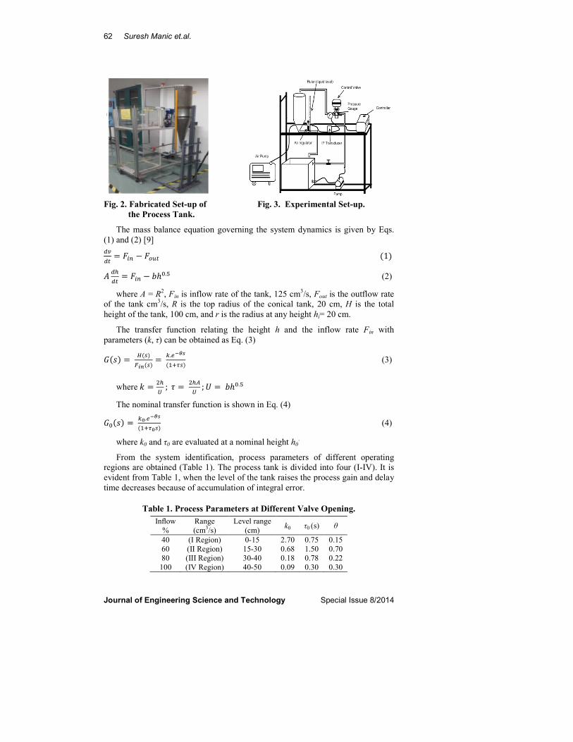
Figure 2 shows the fabricated set up of process tank. The experimental set-up, Fig.
3, consists of conical section at the bottom and cylindrical section at the top open
to the atmosphere. The setup also consists of centrifugal pump, level sensor
arrangement, inlet and outlet valve, air pump, air regulator, IP converter, Pressure
gauge, interfacing card, level indicator and PID controller. The height of the
conical and cylindrical portion of the tank is 50 cm each. The centrifugal pump is
capable of discharging liquid at the rate of 3500 L/h is used and a PVC pipe is
used to connect the pump and the control valve. The minimum voltage applied to
the pump for discharge is 104 V.
2.2. Process modeling
The process transfer function is obtained in terms of the process characteristics
namely the process gain and the process time constant.
62 Suresh Manic et.al.
Journal of Engineering Science and Technology Special Issue 8/2014
Fig. 2. Fabricated Set-up of Fig. 3. Experimental Set-up.
the Process Tank.
The mass balance equation governing the system dynamics is given by Eqs.
(1) and (2) [9]
���� � ��� � �� (1) � ��
�� � ��� � ����� (2)
where A = R2, Fin is inflow rate of the tank, 125 cm
3/s, Fout is the outflow rate
of the tank cm3/s, R is the top radius of the conical tank, 20 cm, H is the total
height of the tank, 100 cm, and r is the radius at any height hi= 20 cm.
The transfer function relating the height h and the inflow rate Fin with
parameters (k, τ) can be obtained as Eq. (3)
�(�) � �(�)���(�) � ���� !
("#$�) (3)
where % � &�' ( ) � &�*
' ( + � �����
The nominal transfer function is shown in Eq. (4)
��(�) � �,��� !("#$,�) (4)
where k0 and τ0 are evaluated at a nominal height h0.
From the system identification, process parameters of different operating
regions are obtained (Table 1). The process tank is divided into four (I-IV). It is
evident from Table 1, when the level of the tank raises the process gain and delay
time decreases because of accumulation of integral error.
Table 1. Process Parameters at Different Valve Opening.
Inflow
%
Range
(cm3/s)
Level range
(cm) k0 τ0 (s) θ
40 (I Region) 0-15 2.70 0.75 0.15
60 (II Region) 15-30 0.68 1.50 0.70
80 (III Region) 30-40 0.18 0.78 0.22
100 (IV Region) 40-50 0.09 0.30 0.30

Real Time Study on Controller Tuning for Nonlinear Hopper Process Tank 63
Journal of Engineering Science and Technology Special Issue 8/2014
2.3. Controller identification
Identified four PID controller tunings methods are as follows:
� Cohen-Coon (C-C) � Internal Model Control (IMC)
� Ziegler and Nichols (Z-N) � Tryeus and Luyben (1997) (TL)
Tuning technique, C-C can be fit to a first order process with dead time model
with the advantages that the procedure does not involve trial and error with only a
single experiment is necessary [9]. As for ZN method is one of the popular
methods among others in tuning PID controllers. The controller settings are easily
calculated and a process model is not necessary [10]. For IMC tuning method, it
involves “lamda tuning (λ)” which is obtained by trial and error. At last TL
method is an alternative method for ZN, with modified formulas for the controller
parameter that provide better performance.
3. Simulation
Block diagram shown in Fig. 4 for the hopper tank process system was created by
using MATLAB Simulink software. The system simulation response is analysed
for 40% to 100% valve opening.
Fig. 4. Simulink Block Diagram for Nonlinear Hopper Process Tank.
4. Criteria of Error Integral Analysis
The best performance of the controller was selected by using three different
tuning criteria IAE, ISE and ITAE. Each of this error integral is a form of penalty
function representing the size and duration of error [11]. Table 2 gives the details
of the tuning methods that aim to minimize the penalty
Table 2. Integral Criteria for Load Changes of PID Tunings.
Error Integral ISE IAE ITAE
-. � /0- 12
3450
a1 1.495 1.435 1.357
b1 -0.945 -0.921 0.947
36 � 3/7
1234
57
a2 1.101 0.878 0.842
b2 0.771 0.749 0.738
38 � /9 3 1234
59
a3 0.560 0.482 0.381
b3 1.006 1.137 0.995
5. Results and Discussion
The hopper tank process includes controller tuning settings using C-C, Z-N, IMC
and LT methods. These tuning method results were compared by means of
MATLAB Simulink software. The performance of the controller is compared on
the time domain specification like rise time, settling time and overshoot.

64 Suresh Manic et.al.
Journal of Engineering Science and Technology Special Issue 8/2014
5.1. Performance analysis based on simulation results
Results are simulated for CC, IMC, ZN and TL methods and discussed in this
section. Four regions of step input have been analysed and observed from 40%
valve opening to 100% valve opening from 20% of initial liquid level.
Figure 5 shows the simulated results of C-C tuning method. From the simulated
results step response for 40% step input is better than 60%, 80% and 100% in terms of
time domain specifications. In the simulation the process system behaved with a faster
response with 2.25 seconds rise time and minimum offset of 0.005 cm as compared to
others step changes. In addition, it had a minimum time delay, 2.13 seconds.
Figure 6 shows the simulated results of IMC tuning method. From the
simulated results step response for 60% step input is better than 40%, 80% and
100% in terms of time domain specifications. However, process responded with
longest time delay among the others step changes, 2.7 seconds. For 40% step
input, it gives an unsteady response with continually aggressive oscillation while
the remaining step inputs have given a large offset value about 0.75 cm.
Fig. 5. Simulated Response Fig. 6. Simulated Response
for C-C Tuning Method. for IMC Tuning Method.
Figure 7 shows the simulated results of ZN tuning method. From the
simulated results step response for 40% step input is better than 60%, 80% and
100% in terms of time domain specifications. 60% step response also shows
better results closer to 40% step change, but 40% step change has a fast response
than 60% with a longer time in achieving steady state or the set point value.
Figure 8 shows the simulated results of LT tuning method. From the simulated
results step response for 40% step input is better than 60%, 80% and 100% in terms
of time domain specifications with fast response and less delay time. 80% and
100% have shown an offset value more than 0.25 cm as well as slow response. As
for 60% step input, it has an aggressive oscillation that persist for a long time.
Fig. 7. Simulated Response for Fig. 8. Simulated Response for
Z-N Tuning Method. L-T Tuning method.

Real Time Study on Controller Tuning for Nonlinear Hopper Process Tank 65
Journal of Engineering Science and Technology Special Issue 8/2014
5.2. Performance analysis based on real time implementation
The tuning rules of CC, IMC, ZN and TL from the simulation performance are
implemented and analysed in real time hopper tank control system, Figs. 9 (a)-(d).
Different set point had been set on each controller tuning settings which clearly
showed that both CC and IMC tuning method had given an aggressive response in
the real time implementation. The response gives an oscillation that persists over
a long time and it does not reach steady state.
(a) Cohen-Coon Method. (b) Ziegler-Nichols Method.
(c) IMC Method (d) Tyreus-Luyben Method.
Fig. 9. Real Time Responses with Different Methods.
The performance of the ZN and TL are much better as compared to others
tuning methods. By comparing ZN and TL tuning, it is observed that TL has lesser
overshoot and faster time that track the set point changes than ZN tuning method.
As over all, TL performs much significantly stable than ZN and others controller
(CC, IMC). Indeed, it has shown oscillatory behaviour and exhibits lesser peak time
as compared to Cohen Coon and IMC controller tuning, but it is completely
different than simulated results as mentioned in previous section. This has been
proven that Cohen Coon and IMC method does not fit well in controlling a closed-
loop control system of a real time hopper tank.
Therefore both ZN and LY tuning method for 80% and 100% has been selected
and tested for the further studies on comparison between simulated and real time
experimental results. Comparison of performance response between ZN and TL
tuning method based on ISE, IAE and ITAE is shown in Table 3.
Table 3. Comparison of Performance Response between ZN and TL Methods.
Tuning rules Zeigler Nichols Tyreus & Luyben
Rise time (min) 10.4 10.1
Settling time (min) 10.2 9.5
Overshoot (cm) 18.8 17

66 Suresh Manic et.al.
Journal of Engineering Science and Technology Special Issue 8/2014
5.3. Comparison of experimental and simulated results
The tuning methods of ZN and TL have been chosen as a comparison between real
time and experimental results of the hopper tank system for 80% step input by
minimum error criterion of ISE, IAE and ITAE. The performances of ZN and TL
tuning method based on error analysis are shown in Table 4 and it is evident that TL
is better than ZN for 80% step input response.
Table 4. Error Analysis for Different Tuning Methods at 80% Step Input.
Method ISE IAE ITAE
ZN (Ziegler & Nichols) 27.86 26.01 25.44
TL (Tyreus & Luyben) 21.38 20.55 19.67
For 80% step input, TL tuning has shown a similarity response with ZN
tuning. From Figs. 10(a) and (b), it shows that both simulated and real time
experimental responses eventually achieved the steady state or set-point of 10 cm.
On the other hand, ZN does not reach the steady state although real time result
has achieved it, at set-point of 7.5 cm. From this observation, both controllers
have proven that at 80% step input for TL will be the suitable tuning method than
ZN tuning method with set-point change and disturbance responses.
(a) Tyreus-Luyben Method.
(b) Ziegler-Nichols controller Method.
Fig. 10. Comparison of 80% Step Input between
Simulated and Real Time Response for Different Methods.

Real Time Study on Controller Tuning for Nonlinear Hopper Process Tank 67
Journal of Engineering Science and Technology Special Issue 8/2014
6. Conclusions
The control systems of a nonlinear hopper tank response vary with different types
of tuning rules. In general from the simulated results as the step input increases,
settling time increase with a larger offset value. However, in decreasing of step
input there is more aggressive response behaviour that exhibits a high overshoot.
The result between simulated and real time experimental will never be exactly
similar due to human factor may occurs when running the process.
Tuning method of TL in PID controller has given good and acceptable
performance with less aggressive oscillation as well as fast settling response at 80%
step input. Besides, it also shows good result for disturbance rejection with fast
settling response. In addition, it has the minimum error integral value and followed
by ZN method. This concludes TL method is most suitable for the chosen nonlinear
hopper process tank based on error analysis.
References
1. Bhuvaneswari, N.S.; Uma, G.; and Rangaswamy, T.R. (2009). Adaprive and
optimal control of a non-linear process using intelligent controllers. Applied
Soft Computing, 9(1), 182-190.
2. Kumar, D.D.; and Meenakshipriya, B. (2012). Design and implementation of
nonlinear system using gain scheduled PI controller. Procedia Engineering,
38, 3105-3112.
3. Anandanatarajan, R.; Chidambaram, M.; and Jayasingh, T. (2006).
Limitations of a PI controller for a first order non-linear process with dead
time. Instrumentation Systems and Automation, 45(1), 185-200.
4. Sung, S.W.; and Lee, I.-B. (1996). Limitations and countermeasures of PID
controllers. Industrial & Engineering Chemistry Research, 35(8), 2596-2610.
5. Madhubala, T.K.; Boopathy, M.; Sarat Chandra, J.; and Radhakrishnan, T.K.
(2004). Development and tuning of fuzzy controller for a conical level
system. Proceedings of the International Conference Intelligent Sensing and
Information Processing, 450-455.
6. Nithya, S.; Sivakumaran, N.; Radhakrishnan, T.K.; and Anantharaman, N.
(2010). Soft computing based controllers implementation for nonlinear
process in real time. Proceedings of the World Congress on Engineering and
Computer Science, Volume II, 264-268.
7. Anandanatarajan, R.; Chidambaram, M.; Jayasingh, T. (2004). Imporved
design of FLC for a first order nonlinear process with dead time. Proceedings
of International Conference on Intelligent Sensing and Information
Processing, 466-471.
8. Araki, M. (2008). PID control. Encyclopedia of Life Support Systems
(EOLSS), 2(1), 26.
9. Suresh, K.; and Balu, K. (2007), Design of fuzzy estimator to assist fault
recovery in a non-linear system. International Journal of Computer Science
and Network Security Publications, 7(5), 1-7.
10. Romagnoli, J.A.; Palazoglu, A. (2012). Introduction to process control. CRC press.
11. King, M. (2001). Process control – A practical approach. Wiley press.


![Tuning New Fuzzy Control for Nonlinear Second Order System · Lyapunov-based control and adaptive control [1, 6- 11]. Fuzzy Logic controller (FLC) is a powerful model-free nonlinear](https://static.fdocuments.net/doc/165x107/5f69b86d4a733a4cfa7f61f7/tuning-new-fuzzy-control-for-nonlinear-second-order-system-lyapunov-based-control.jpg)