Controlled axis Absolute Interpolation SM 400
6
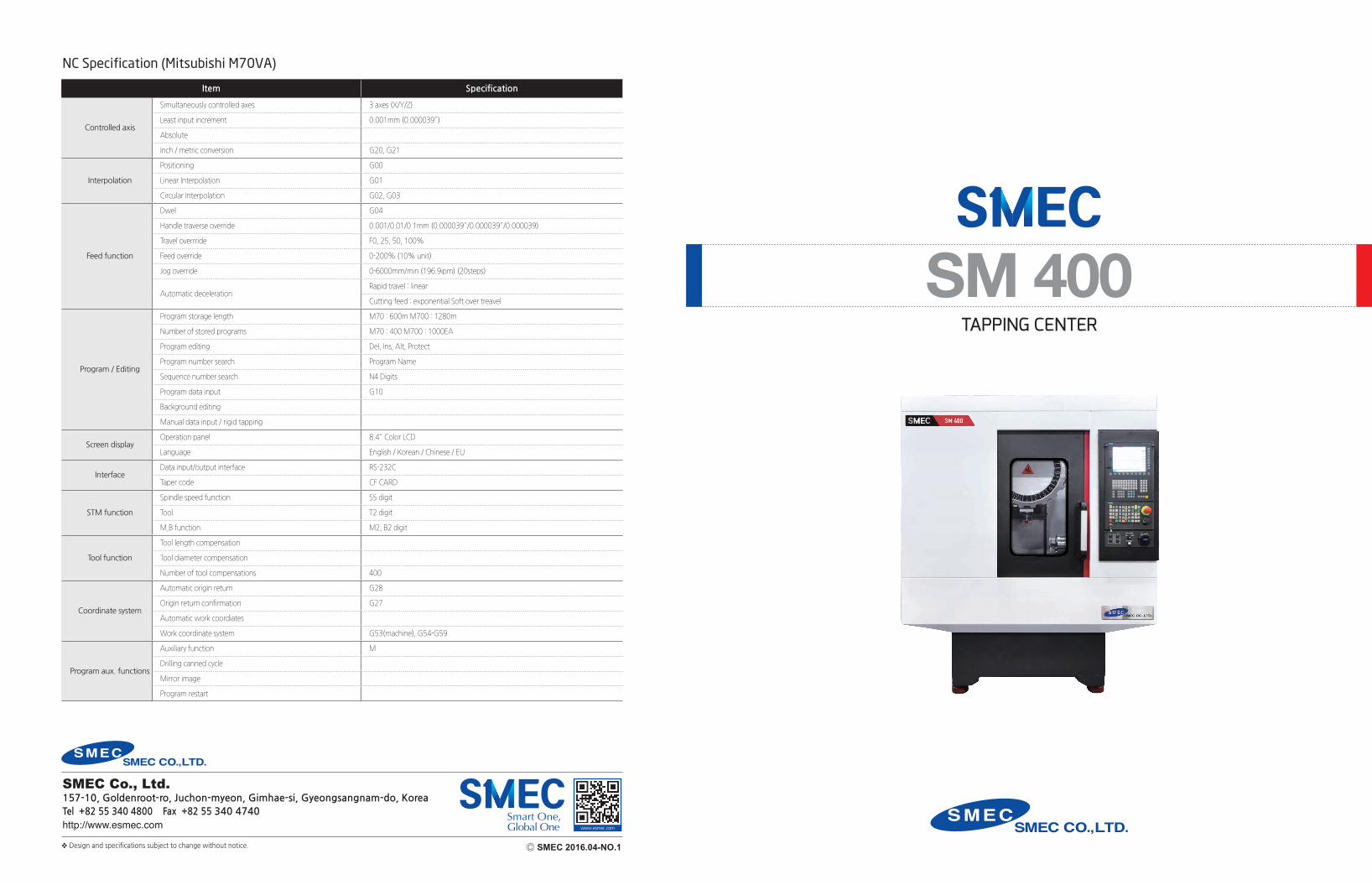
NC Specification (Mitsubishi M70VA) Item Specification Controlled axis Simultaneously controlled axes 3 axes (X/Y/Z) Least input increment 0.001mm (0.000039″) Absolute Inch / metric conversion G20, G21 Interpolation Positioning G00 Linear Interpolation G01 Circular Interpolation G02, G03 Feed function Dwel G04 Handle traverse override 0.001/0.01/0.1mm (0.000039″/0.000039″/0.000039) Travel overrride F0, 25, 50, 100% Feed override 0-200% (10% unit) Jog override 0-6000mm/min (196.9ipm) (20steps) Automatic deceleration Rapid travel : linear Cutting feed : exponential Soft over treavel Program / Editing Program storage length M70 : 600m M700 : 1280m Number of stored programs M70 : 400 M700 : 1000EA Program editing Del, Ins, Alt, Protect Program number search Program Name Sequence number search N4 Digits Program data input G10 Background editing Manual data input / rigid tapping Screen display Operation panel 8.4″ Color LCD Language English / Korean / Chinese / EU Interface Data input/output interface RS-232C Taper code CF CARD STM function Spindle speed function S5 digit Tool T2 digit M,B function M2, B2 digit Tool function Tool length compensation Tool diameter compensation Number of tool compensations 400 Coordinate system Automatic origin return G28 Origin return confirmation G27 Automatic work coordiates Work coordinate system G53(machine), G54-G59 Program aux. functions Auxiliary function M Drilling canned cycle Mirror image Program restart TAPPING CENTER SM 400 Ⓒ SMEC 2016.04-NO.1 ❖ Design and specifications subject to change without notice. www.esmec.com SMEC Co., Ltd. 157-10, Goldenroot-ro, Juchon-myeon, Gimhae-si, Gyeongsangnam-do, Korea Tel +82 55 340 4800 Fax +82 55 340 4740 http://www.esmec.com
Transcript of Controlled axis Absolute Interpolation SM 400
NC Specification (Mitsubishi M70VA)
Item Specification
Controlled axis
Simultaneously controlled axes 3 axes (X/Y/Z)
Least input increment 0.001mm (0.000039″)
Absolute
Inch / metric conversion G20, G21
Interpolation
Positioning G00
Linear Interpolation G01
Circular Interpolation G02, G03
Feed function
Dwel G04
Handle traverse override 0.001/0.01/0.1mm (0.000039″/0.000039″/0.000039)
Travel overrride F0, 25, 50, 100%
Feed override 0-200% (10% unit)
Jog override 0-6000mm/min (196.9ipm) (20steps)
Automatic decelerationRapid travel : linear
Cutting feed : exponential Soft over treavel
Program / Editing
Program storage length M70 : 600m M700 : 1280m
Number of stored programs M70 : 400 M700 : 1000EA
Program editing Del, Ins, Alt, Protect
Program number search Program Name
Sequence number search N4 Digits
Program data input G10
Background editing
Manual data input / rigid tapping
Screen displayOperation panel 8.4″ Color LCD
Language English / Korean / Chinese / EU
InterfaceData input/output interface RS-232C
Taper code CF CARD
STM function
Spindle speed function S5 digit
Tool T2 digit
M,B function M2, B2 digit
Tool function
Tool length compensation
Tool diameter compensation
Number of tool compensations 400
Coordinate system
Automatic origin return G28
Origin return confirmation G27
Automatic work coordiates
Work coordinate system G53(machine), G54-G59
Program aux. functions
Auxiliary function M
Drilling canned cycle
Mirror image
Program restart
TAPPING CENTER
SM 400
Ⓒ SMEC 2016.04-NO.1❖ Design and specifications subject to change without notice.
www.esmec.com
SMEC Co., Ltd.157-10, Goldenroot-ro, Juchon-myeon, Gimhae-si, Gyeongsangnam-do, KoreaTel +82 55 340 4800 Fax +82 55 340 4740http://www.esmec.com
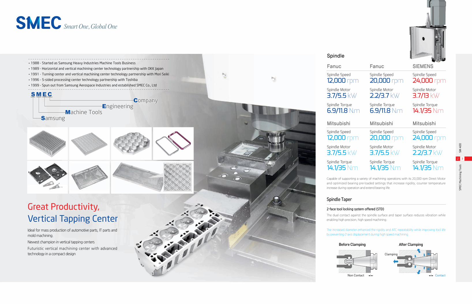
Ideal for mass production of automotive parts, IT parts and mold machining.
Newest champion in vertical tapping centers
Futuristic vertical machining center with advanced technology in a compact design
Great Productivity, Vertical Tapping Center
Capable of supporting a variety of machining operations with its 20,000 rpm Direct Motor
and optimized bearing pre-loaded settings that increase rigidity, counter temperature
increase during operation and extend bearing life.
The increased diameter enhanced the rigidity and ATC repeatability while improving tool life
by preventing Z-axis displacement during high speed machining.
Spindle Taper
2-face tool locking system offered (STD)
The dual contact against the spindle surface and taper surface reduces vibration while
enabling high precision, high speed machining.
Fanuc
Spindle Torque
6.9/11.8 N.m
Spindle Speed
12,000 rpmSpindle Motor
3.7/5.5 kW
Mitsubishi
Spindle Torque
14.1/35 N.m
Spindle Speed
12,000 rpmSpindle Motor
3.7/5.5 kW
Fanuc
Spindle Torque
6.9/11.8 N.m
Spindle Speed
20,000 rpmSpindle Motor
2.2/3.7 kW
SIEMENS
Spindle Torque
14.1/35 N.m
Spindle Speed
24,000 rpmSpindle Motor
3.7/13 kW
Mitsubishi
Spindle Torque
14.1/35 N.m
Spindle Speed
20,000 rpmSpindle Motor
3.7/5.5 kW
Mitsubishi
Spindle Torque
14.1/35 N.m
Spindle Speed
24,000 rpmSpindle Motor
2.2/3.7 kW
Smart One, Global One
SMEC
Mac
hini
ng T
ools
SM 4
00
2 3
Before Clamping After Clamping
Clamping
Non Contact Contact
Spindle
•1988 - Started as Samsung Heavy Industries Machine Tools Business
•1989 - Horizontal and vertical machining center technology partnership with OKK Japan
•1991 - Turning center and vertical machining center technology partnership with Mori Seiki
•1996 - 5-sided processing center technology partnership with Toshiba
•1999 - Spun out from Samsung Aerospace Industries and established SMEC Co., Ltd
SMEC Company Engineering Machine Tools Samsung
SMEC
Mac
hini
ng T
ools
SM 4
00
4 5
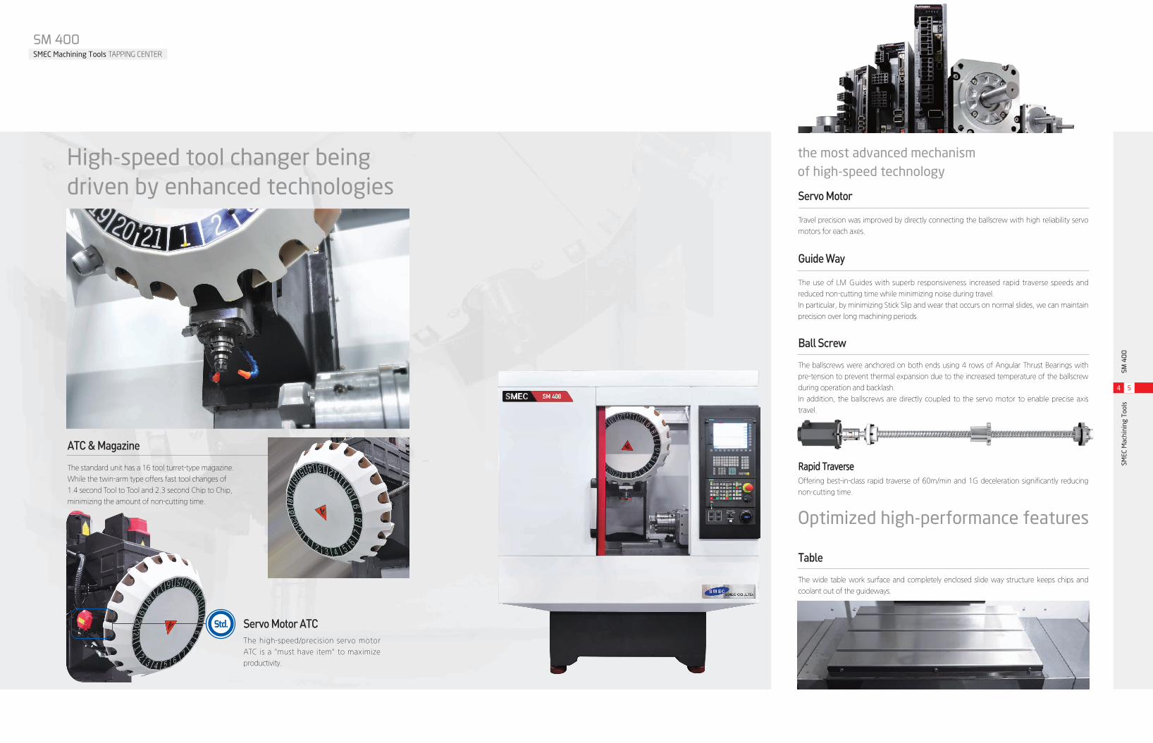
Servo Motor
Travel precision was improved by directly connecting the ballscrew with high reliability servo
motors for each axes.
Guide Way
The use of LM Guides with superb responsiveness increased rapid traverse speeds and
reduced non-cutting time while minimizing noise during travel.
In particular, by minimizing Stick Slip and wear that occurs on normal slides, we can maintain
precision over long machining periods.
Rapid TraverseOffering best-in-class rapid traverse of 60m/min and 1G deceleration significantly reducing
non-cutting time.
ATC & Magazine
The standard unit has a 16 tool turret-type magazine.
While the twin-arm type offers fast tool changes of
1.4 second Tool to Tool and 2.3 second Chip to Chip,
minimizing the amount of non-cutting time.
Servo Motor ATCThe high-speed/precision servo motor
ATC is a "must have item" to maximize
productivity.
Ball Screw
The ballscrews were anchored on both ends using 4 rows of Angular Thrust Bearings with
pre-tension to prevent thermal expansion due to the increased temperature of the ballscrew
during operation and backlash.
In addition, the ballscrews are directly coupled to the servo motor to enable precise axis
travel.
Table
The wide table work surface and completely enclosed slide way structure keeps chips and
coolant out of the guideways.
the most advanced mechanism of high-speed technology
Optimized high-performance features
High-speed tool changer being driven by enhanced technologies
Std.
SM 400SMEC Machining Tools TAPPING CENTER

SMEC
Mac
hini
ng T
ools
SM 4
00
6 7
Centralized Operation Panel
- 8.4 inch color LCD
- Semipermanent LED Lamp
- Swivel operation panel for convenient operation
and work access
High reliability components used in the electric cabinet to reduce frequency of breakdown.
- Magnet switch, circuit breaker, Key S/W (Fuji)
- Relay (Weidmuller, Omron)
Chip Conveyor
Bucket Option
Left Chip Conveyor OptionRight Chip Conveyor Option
Z-Axis
350 mm
X-Axis
530 mmY-Axis
400 mm
Automatic Lubrication Dispenser
Automatic lubrication dispenser that reliably dispenses the
required amount of lubrication to the required travel axes.
Lubrication is only dispensed when the travel axes is in
operation, reducing the amount of lubrication that is
consumed.
Spindle Head Cooling System
[20,000 / 24,000rpm]
For long-term continuous high-
speed operation, a coolant system
may be installed to maintain room
temperature. The coolant system
circulates coolant oil around
the spindle bearings to prevent
thermal expansion due to the
spindle temperature, ensuring
high precision machining.
(12,000rpm : Opt.)Bed Coolant STD.
Centralized Utility Alcove
Operation status of lubrication, air supply,
etc. can easily be checked.
Std.
X-axisY-axis
Work Space
(Stroke)
Z-axis
SM 400SMEC Machining Tools TAPPING CENTER
Unit : inch
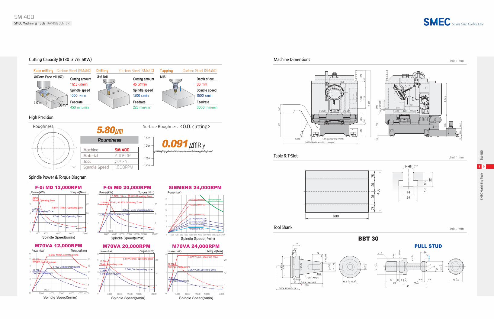
Machine SM 400Material A 1050PTool Ø25×4TSpindle Speed 1,500RPM
Roundness
5.80㎛
20㎛
Roughness
BBT 30PULL STUD
Surface Roughness <O.D. cutting>
0.091㎛ R y12㎛
10㎛
-10㎛
-12㎛
SMEC
Mac
hini
ng T
ools
SM 4
00
8 9
Machine Dimensions Unit : mmCutting Capacity (BT30 3.7/5.5KW)
Spindle Power & Torque Diagram
High Precision
Table & T-Slot Unit : mm
Tool Shank Unit : mm
Smart One, Global One
2,681(Machine+Vhip conveyor)
1,666(Machine Width)1,015
852
429
50
770
500
1,145
778
262
280
15
150Z-ST:350
385
1,186
370
635
523
Y-ST:200Y-ST:265 Y-ST:265 Y-ST:200400600
721
1,014
2,370
300
600
400
Spindle Speed(r/min)1500 3000 6000 9000 12000
Torque(Nm)
10
20
30
40
5.5kW, 30min. Operating Zone
3.7kW, Cont. Operating Zone
Power(kW)
0
2
4
6
8
F-0i MD 12,000RPM
23.5Nm, Cont. Operating Zone
35Nm, 30min, Operating Zone
Spindle Speed(r/min)2000
2800
4000 6000 8000 1200010000
4
8
12
16
20
Power(kW) Torque(Nm)
5
6
4
3
2
1
0
M70VA 12,000RPM
3.7kW Cont.operating zone
5.5kW 15min. operating zone
18.8Nm 25%ED operating zone
12.6Nm Cont.operating zone
Spindle Speed(r/min)2000 8000 12000 16000 24000
2
12
20
Torque(Nm)Power(kW)4
2
0
M70VA 24,000RPM
2.2kW Cont.operating zone
3.7kW 15min. operating zone
17.7Nm 15min. operating zone
7.0Nm Cont.operating zone
Spindle Speed(r/min)0 2000
4
8
12
16
20
24
4000 6000 8000 10000 12000 14000 16000 18000 20000 22000 24000
Pmax3(22.6kW:60A)
Pmax2(18.8kW:51A)
Pmax1(11.8kW:33A)
S6-10%(8.8kW:43.3A)
Spannungsgrenzkennlinievoltage limiting Characteristics
S6-25%(6.7kW:32.9A)S6-40%(5.3kW:26A)
PS1(3.5kW:15.5A)
Power(kW)SIEMENS 24,000RPM
Spindle Speed(r/min)2000 8000 12000 16000 20000
4
12
22
Torque(Nm)Power(kW)
5
6
3
2
1
0
M70VA 20,000RPM
3.7kW Cont.operating zone
5.5kW 30min. operating zone17.7Nm 30min. operating zone
7.0Nm Cont.operating zone
50 mm2.0 mm
Ø63mm Face mill (5Z)
112.5 ㎤/min
Cutting amount
1000 r/min
Spindle speed
450 mm/min
Feedrate
Face milling Carbon Steel (SM45C)Ø16 Drill
45 ㎤/min
Cutting amount
1200 r/min
Spindle speed
225 mm/min
Feedrate
Drilling Carbon Steel (SM45C)M16
30 mm
Depth of cut
1500 r/min
Spindle speed
3000 mm/min
Feedrate
Tapping Carbon Steel (SM45C)
Power(kW)
Spindle Speed(r/min)
Torque(Nm)
2000 4000 6000 8000 10000 12000 20000
30000
1
2
3
2
8
12
43.7kW, 15min, S3 40% Operating Zone
2.2kW, Cont. Operating Zone
11.8Nm, 15min, S3 40% Operating Zone
7Nm, Const. Operating Zone
3.7kW, 15min, S3 40% Operating Zone
2.2kW, Cont. Operating Zone
11.8Nm, 15min, S3 40% Operating Zone
7Nm, Const. Operating Zone
F-0i MD 20,000RPM
SM 400SMEC Machining Tools TAPPING CENTER

SM 400SMEC Machining Tools TAPPING CENTER
SMEC
Mac
hini
ng T
ools
SM 4
00
10 11
Smart One, Global One
Major Specifications NC Specifications (FANUC 0i-MD)
Item Specification F 0i-MD
Controlled axis
Controlled axes X,Y,Z,(A,B)
Max. controlled axes 4(6) AXIS
Max. simultaneously controlled axes 4
Least input increment 0.001mm / 0.0001" ◯
Operation functions
Manual handle feed X1, X10, X100 ◯
Feed per minute G94 ◯
Feed per revolution G95 ◯
Interpolation functions
Linear interpolation G01 ◯
Circular interpolation G02, G03 ◯
Dwell G04 ◯
Cylindrical interpolation G70.1 ◯
Reference position return G28 ◯
Reference position return check G27 ◯
Feed functionRapid traverse feedrate override F0, 25%, 50%, 100% ◯
Feedrate override 0~200%
Spindle functionSpindle override ◯
Rigid tapping ◯
Tool functions
Tool function T4-Digt / T2-Digt T2-Digt
Tool nose radius compensation G40 ~ G42 ◯
Tool offset pairs 400
Tool geometry / wear offset GEOMETRY & WEAR DATA ◯
Tool life management ◯
Tool path graphic display ◯
Automatic tool compensation ◯
Program input
Absolute / incremental programming ◯
Multiple repetitive cycle G70 ~ G76 ◯
Canned cycle G90, G92, G94 ◯
Inch / metric conversion G20 / G21 ◯
Program restart ◯
Retraction for rigid tapping ◯
Max. programmable dimension ±99999.999mm/±9999.9999" ◯
M function M3 digit ◯
Custom macro ◯
Canned cycle for drilling ◯
Direct drawing dimension programming ◯
Programmable data input G10 ◯
Optional block skip ◯
Workpiece coordinate system G52 ~ G59 ◯
Number of registerable programs 400EA
Setting and display
Help function ALARM & OPERATION DISPLAY ◯
Run hour / parts count display RUNNING TIME & PART NO. DISPLAY ◯
Spindle & servo load display SPINDLE & SERVO LOAD DISPLAY ◯
Self-diagnosis function ◯
Extended part program editing COPY,MOVE, CHANGE OF NC PROGRAM ◯
Display screen 8.4" color
Data input/outputMemory card input / output ◯
USB memory input / output ◯
Editing operation Part program storage size 512Kbyte(1280m) 1280M
Manual guide i Manual Guide I Opt.
DESCRIPTION SM 400 (Fanuc) SM 400 (Mitsubishi) SM 400 (Siemens)
Travel
X axis mm 530 530 530
Y axis mm 400 400 400
Z axis mm 350 350 350
Distance from spindle center to column mm 523 523 523
Distance from spindle nose to table surface mm 150~500 150~500 150~500
Table
Table surface mm 14H8 × p125 × 3ea 14H8 × p125 × 3ea 14H8 × p125 × 3ea
Loading capacity kg 200 200 200
Table size mm 600 × 400 600 × 400 600 × 400
Spindle
Spindle speed r/min 12,000 (20,000) 12,000 (20,000 / 24,000) 24,000
Tool shank ISO #30 7/24 TAPER ISO #30 7/24 TAPER ISO #30 7/24 TAPER
Motor (Cont. /30min) kW 3.7/5.5 (2.2/3.7) 3.7/5.5, 3.7/5.5, 2.2/3.7 3.7/13
Torque (Cont. /30min) N.m 6.9/11.8 14.1/35 (12.4/23.6) 14.1/35 (12.4/23.6)
Feedrate
Rapid traverse(X/Y/Z) m/min 60 / 60 / 60 60 / 60 / 60 60 / 60 / 60
Slide type - LM GUIDE LM GUIDE LM GUIDE
Cutting feedrate(X/Y/Z) mm/min 1~30,000 1~30,000 1~30,000
Feedback system Absolute Absolute Absolute
Feed rate(X/Y/Z/B) kW 3 / 3 / 3 2.2 / 2.2 / 2.2 3 / 3 / 3
ATC
Tool shank BBT 30 BBT 30 BBT 30
Magazine capacity 21 21 21
Max. tool dia. [adjacent empty] mm Ø80[Ø60] Ø80[Ø60] Ø80[Ø60]
Max. tool length mm 150 150 150
Max. tool weight kgf 3 3 3
Tool selection method - Fixed address Fixed address Fixed address
Tool change method - Umbrella Umbrella Umbrella
Tool changing time (T-T) sec 1.4 1.4 1.4
Chip-to-chip time sec 2.3 2.3 2.3
Compressed air supply Mpa 0.4~0.6 0.4~0.6 0.4~0.6
Power supply kVA 30 30 30
Floor space (L×W×H) mm 1,654 × 1,765 × 2,652 1,654 × 1,765 × 2,652 1,654 × 1,765 × 2,652
Machine weight kgf 3,800 3,800 3,800
CNC system Fanuc 0i-MD Mitsubishi M70VA SIEMENS
※Design and specifications are subject to change without notification. ( ) : Optional
- Air gun
- Air blow
- Coolant gun
- Rotary table
- Oil skimmer
- Coolant level gauge
- Through spindle coolant (TSC 20Bar)
- Tool length measurement system (Automatic)
- Spindle oil cooler
- HYD unit
- Mist collector (Top cover must be installed)
- Top cover (Recommended when using TSC)
- Lift-up chip conveyor (HINGE TYPE / SCRAPPER TYPE)
- Full splash guard
- Coolant system
- Leveling parts (Level plate, bolt, etc.)
- Standard tools and tool box
- Lubrication system
- Work light (LED)
- 3 step patrol lamp
- Rigid tapping
- Spindle override
- Spindle
- Door inter lock
- Bed flushing
- KCS specification
- MPG handle
- Manual and parts list
Standard Accessories Optional Accessories