
Control User Guide - · PDF filemanufacturer reserves the right to change the specification of...
158
Control User Guide Unidrive M200/M201 Variable Speed AC drive for induction motors Part Number: 0478-0351-02 Issue: 2
Transcript of Control User Guide - · PDF filemanufacturer reserves the right to change the specification of...

Control User Guide
Unidrive M200/M201
Variable Speed AC drive for induction motors
Part Number: 0478-0351-02Issue: 2

Original InstructionsFor the purposes of compliance with the EU Machinery Directive 2006/42/EC, the English version of this manual is the Original
Instructions. Manuals in other languages are Translations of the Original Instructions.
DocumentationManuals are available to download from the following locations:
http://www.emersonindustrial.com/en-EN/controltechniques/downloads/userguidesandsoftware/Pages/downloads.aspx
http://www.emersonindustrial.com/en-EN/leroy-somer-motors-drives/downloads/Pages/manuals.aspx
The information contained in the manuals is believed to be correct at the time of printing and does not form part of any contract. The manufacturer reserves the right to change the specification of the product and its performance, and the contents of the manual, without notice.
Incorrect installation and operationThe manufacturer accepts no liability for any consequences resulting from inappropriate, negligent or incorrect installation or incorrect adjustment of the operating parameters.
Environmental policyWe operate an Environmental Management System (EMS) certified to the International Standard ISO 14001.
Further information on our Environmental Policy can be found at:
http://www.emersonindustrial.com/en-EN/controltechniques/aboutus/environment/environmentalpolicyctuk/Pages/environmentalpolicyctuk.aspx
Disposal and Recycling
REACH legislationEC Regulation 1907/2006 on the Registration, Evaluation, Authorisation and restriction of Chemicals (REACH) requires the supplier of an article to inform the recipient if it contains more than a specified proportion of any substance which is considered by the European Chemicals Agency (ECHA) to be a Substance of Very High Concern (SVHC) and is therefore listed by them as a candidate for compulsory authorisation.
Further information on our compliance with REACH can be found at:
www.emersonindustrial.com/en-EN/controltechniques/aboutus/environment/reachregulation/Pages/reachregulation.aspx
Registered in England and Wales. Company Reg. No. 01236886.
CopyrightThe contents of this publication are believed to be correct at the time of printing. In the interests of a commitment to a policy of continuous development and improvement, the manufacturer reserves the right to change the specification of the product or its performance, or the contents of the guide, without notice.
All rights reserved. No parts of this guide may be reproduced or transmitted in any form or by any means, electrical or mechanical including photocopying, recording or by an information storage or retrieval system, without permission in writing from the publisher.
Copyright: © May 2017 Control Techniques Ltd
Issue Number: 2
When electronic products reach the end of their useful life, they must not be disposed of along with domestic waste but should be recycled by a specialist recycler of electronic equipment. The products are designed to be easily dismantled into their major component parts for efficient recycling. The majority of materials used in the product are suitable for recycling.Product packaging is of good quality and can be re-used. Large products are packed in wooden crates. Smaller products are packaged in strong cardboard cartons which have a high recycled fibre content. Cartons can be re-used and recycled. Polythene, used in protective film and bags for wrapping the product, can be recycled. When preparing to recycle or dispose of any product or packaging, please observe local legislation and best practice.
Control Techniques LtdThe GroNewtownPowysSY16 3BEUK
Moteurs Leroy-SomerUsine des AgriersBoulevard Marcellin LeroyCS1001516915 Angouleme Cedex 9France

How to use this guideThis guide is intended to be used in conjunction with the appropriate Power Installation Guide. The Power Installation Guide gives information necessary to physically install the drive. This guide gives information on drive configuration, operation and optimization.
There are specific safety warnings throughout this guide, located in the relevant sections. In addition, Chapter 1 Safety information contains general safety information. It is essential that the warnings are observed and the information considered when working with or designing a system using the drive.
This map of the user guide helps to find the right sections for the task you wish to complete, but for specific information, refer to Contents on page 4:
NOTE
1 Safety information
2 Product information
3 Mechanical installation
4 Electrical installation
5 Getting started
6 Basic parameters
7 Running the motor
8 Optimization
9 NV media card operation
11 Advanced parameters
10 Onboard PLC
12 Diagnostics
13 UL listing information

Contents
1 Safety information .................................71.1 Warnings, Cautions and Notes .............................71.2 Installation and Use ...............................................71.3 Enclosure ..............................................................71.4 Competence of the installer ..................................71.5 Electric Shock and Fire Hazards ...........................71.6 Electrical installation ..............................................71.7 Setting up, commissioning and maintenance ........81.8 Safety of machinery, safety-critical applications ...81.9 Electromagnetic compatibility (EMC) ....................81.10 Copyright ...............................................................8
2 Product information ..............................92.1 Introduction ...........................................................92.2 Model number .......................................................92.3 Ratings ................................................................102.4 Operating modes .................................................112.5 Keypad and display .............................................112.6 Nameplate description ........................................122.7 Options ................................................................13
3 Mechanical installation .......................153.1 Installing / removing options ................................153.2 Real time clock battery replacement ...................18
4 Electrical installation ...........................194.1 24 Vdc supply ......................................................194.2 Communication connections ...............................194.3 Control connections ............................................20
5 Getting started .....................................235.1 Understanding the display ...................................235.2 Keypad operation ................................................235.3 Menu structure ....................................................255.4 Menu 0 ................................................................255.5 Advanced menus ................................................265.6 Changing the operating mode .............................265.7 Saving parameters ..............................................265.8 Restoring parameter defaults ..............................275.9 Parameter access level and security ..................275.10 Displaying parameters with non-default values only ......................................................................275.11 Displaying destination parameters only ..............285.12 Communications .................................................28
6 Basic parameters .................................296.1 Menu 0: Basic parameters ..................................296.2 Parameter descriptions .......................................346.3 Control terminal configurations and wiring ..........35
7 Running the motor ..............................417.1 Quick start connections .......................................417.2 Changing the operating mode .............................417.3 Quick start commissioning / start-up ...................46
8 Optimization ........................................ 488.1 Motor map parameters ....................................... 488.2 Maximum motor rated current ............................ 548.3 Current limits ...................................................... 548.4 Motor thermal protection .................................... 548.5 Switching frequency ........................................... 558.6 CT Modbus RTU specification ........................... 56
9 NV Media Card .................................... 619.1 Introduction ........................................................ 619.2 SD card support ................................................. 619.3 NV Media Card parameters ............................... 649.4 NV Media Card trips ........................................... 649.5 Data block header information ........................... 64
10 Onboard PLC ....................................... 6510.1 Onboard PLC and Machine Control Studio ........ 6510.2 Benefits .............................................................. 6510.3 Features ............................................................. 6510.4 Onboard PLC parameters .................................. 6610.5 Onboard PLC trips ............................................. 66
11 Advanced parameters ........................ 6711.1 Parameter ranges and Variable minimum/
maximums: ......................................................... 7011.2 Menu 1: Frequency reference ............................ 7811.3 Menu 2: Ramps .................................................. 8211.4 Menu 3: Frequency control ................................ 8511.5 Menu 4: Torque and current control ................... 9011.6 Menu 5: Motor control ........................................ 9311.7 Menu 6: Sequencer and clock ............................ 9811.8 Menu 7: Analog I/O .......................................... 10111.9 Menu 8: Digital I/O ........................................... 10411.10 Menu 9: Programmable logic, motorized pot, binary sum and timers ...................................... 10811.11 Menu 10: Status and trips ................................ 11211.12 Menu 11: General drive set-up ......................... 11411.13 Menu 12: Threshold detectors, variable selectors and brake control function ................. 11511.14 Menu 14: User PID controller ........................... 12011.15 Menu 15: Option module set-up ....................... 12311.16 Menu 18: Application menu 1 ........................... 12411.17 Menu 20: Application menu 2 ........................... 12511.18 Menu 21: Second motor parameters ................ 12611.19 Menu 22: Additional Menu 0 set-up ................. 12711.20 Menu 24: Option Module Application ............... 128
4 Unidrive M200 / M201 Control User Guide Issue Number: 2
12 Diagnostics ........................................12912.1 Status modes (Keypad and LED status) ...........12912.2 Trip indications ..................................................12912.3 Identifying a trip / trip source .............................12912.4 Trips, Sub-trip numbers ....................................13012.5 Internal / Hardware trips ....................................15012.6 Alarm indications ...............................................15012.7 Status indications ..............................................15112.8 Displaying the trip history ..................................15112.9 Behaviour of the drive when tripped .................152
13 UL Listing ...........................................15313.1 UL file reference ................................................15313.2 Option modules, kits and accessories ..............15313.3 Enclosure ratings ..............................................15313.4 Mounting ...........................................................15313.5 Environment ......................................................15313.6 Electrical Installation .........................................15313.7 Motor overload protection and thermal memory retention ..............................................15313.8 External Class 2 supply ....................................15313.9 Modular Drive Systems .....................................15313.10 Requirement for Transient Surge Suppression .154
Unidrive M200 / M201 Control User Guide 5Issue Number: 2

6 Unidrive M200 / M201 Control User Guide Issue Number: 2
This declaration is issued under the sole responsibility of the manufacturer. The object of the declaration is in conformity with the relevant Union
harmonization legislation. The declaration applies to the variable speed drive products shown below:
The model number may be followed by additional characters that do not affect the ratings.
The variable speed drive products listed above have been designed and manufactured in accordance with the following European harmonized
standards:
EN 61000-3-2:2014 Applicable where input current < 16 A. No limits apply for professional equipment where input power 1 kW.
These products comply with the Restriction of Hazardous Substances Directive (2011/65/EU), the Low Voltage Directive (2014/35/EU) and the Electromagnetic Compatibility Directive (2014/30/EU).
G Williams
Vice President, Technology
Date: 25th April 2017
These electronic drive products are intended to be used with appropriate motors, controllers, electrical protection components and other equipment to form complete end products or systems. Compliance with safety and EMC regulations depends upon installing and configuring drives correctly, including using the specified input filters.
The drives must be installed only by professional installers who are familiar with requirements for safety and EMC. Refer to the Product Documentation. An EMC data sheet is available giving detailed information. The assembler is responsible for ensuring that the end product or system complies with all the relevant laws in the country where it is to be used.
EU Declaration of Conformity
Nidec Control Techniques Ltd, The Gro, Newtown, Powys, UK. SY16 3BE.
Model number Interpretation Nomenclature aaaa - bbc ddddde
aaaa Basic seriesM100, M101, M200, M201, M300, M400, M600, M700, M701, M702, M708, M709, M750, M751, M753, M754, F300, H300, E200, E300, HS30, HS70, HS71, HS72, M000, RECT
bb Frame size 01, 02, 03, 04, 05, 06, 07, 08, 09, 10, 11
c Voltage rating 1 = 100 V, 2 = 200 V, 4 = 400 V, 5 = 575 V, 6 = 690 V
ddddd Current rating Example 01000 = 100 A
e Drive formatA = 6P Rectifier + Inverter (internal choke), D = Inverter, E = 6P Rectifier + Inverter (external choke), T = 12P Rectifier + Inverter (external choke)
EN 61800-5-1:2007 Adjustable speed electrical power drive systems - Part 5-1: Safety requirements - Electrical, thermal and energy
EN 61800-3: 2004+A1:2012 Adjustable speed electrical power drive systems - Part 3: EMC requirements and specific test methods
EN 61000-6-2:2005 Electromagnetic compatibility (EMC) - Part 6-2: Generic standards - Immunity for industrial environments
EN 61000-6-4: 2007+ A1:2011Electromagnetic compatibility (EMC) - Part 6-4: Generic standards - Emission standard for industrial environments
EN 61000-3-2:2014Electromagnetic compatibility (EMC) - Part 3-2: Limits for harmonic current emissions (equipment input current ≤16 A per phase)
EN 61000-3-3:2013Electromagnetic compatibility (EMC) - Part 3-3: Limitation of voltage changes, voltage fluctuations and flicker in public, low voltage supply systems, for equipment with rated current ≤16 A per phase and not subject to conditional connection

Safety information
Product information
Mechanical installation
Electrical installation
Getting started
Basic parameters
Running the motor
OptimizationNV Media
CardOnboard
PLCAdvanced
parametersDiagnostics UL Listing
1 Safety information
1.1 Warnings, Cautions and Notes
A Note contains information which helps to ensure correct operation of the product.
1.2 Installation and UseThe information given in this publication is derived from tests and calculations on sample products. It is provided to assist in the correct application of the product, and is believed to correctly reflect the behaviour of the product when operated in accordance with the instructions. The provision of this data does not form part of any contract or undertaking. Where a statement of conformity is made with a specific standard, the manufacturer takes all reasonable measures to ensure that its products are in conformance. Where specific values are given these are subject to normal engineering variations between samples of the same product. They may also be affected by the operating environment and details of the installation arrangement.
The manufacturer accepts no liability for any consequences resulting from inappropriate, negligent or incorrect installation of the equipment.
1.3 EnclosureUnless stated otherwise in the installation instructions, the product is intended to be mounted in an enclosure which prevents access except by trained and authorized personnel, and which prevents the ingress of contamination. It is designed for use in an environment classified as pollution degree 2 in accordance with IEC 60664-1. This means that only dry, non-conducting contamination is acceptable.
1.4 Competence of the installerInstallation should be carried out by professional installers who are familiar with the requirements for safety and EMC. The installer is responsible for ensuring that the end product or system complies with all the relevant laws in the country where it is to be used.
1.5 Electric Shock and Fire Hazards
1.5.1 AC supplyThe AC supply must be isolated before any servicing work is performed, other than adjustments to the settings or parameters specified in the manual.
1.5.2 Live terminalsSome types of signal and control lines carry hazardous voltages (120/ 240 V) and can cause severe electric shock and may be lethal.
1.5.3 Stored chargeSome products contain capacitors that remain charged to a potentially lethal voltage after the power supply has been disconnected. It is recommended that the power supply is isolated at least ten minutes before working on the equipment.
1.6 Electrical installation1.6.1 Protective Ground (Earth) connectionThe ground loop impedance must conform to the requirements of local safety regulations. The equipment must be grounded by a connection capable of carrying the prospective fault current until the protective device (fuse or circuit breaker) disconnects the supply. The ground connections must be inspected and tested at appropriate intervals.
1.6.2 FusesThe supply to the equipment must be installed with suitable protection against overload and short-circuits. The tables in the relevant documentation show recommended fuse ratings. Failure to observe these installation instructions could result in fire.
1.6.3 CablesThe cable sizes in the relevant documentation are only a guide. The mounting and grouping of cables affects their current-carrying capacity, in some cases smaller cables may be acceptable but in other cases a larger cable is required to avoid excessive temperature or voltage drop. Refer to local wiring regulations for the correct size of cables. Failure to observe these installation instructions could result in fire.
1.6.4 Terminal connections and torque settingsLoose power connections can be a fire risk. Always ensure that terminals are tightened to the specified torques. Refer to the tables in the relevant documentation.
1.6.5 High voltage insulation (flash) testingHigh voltage insulation (flash) testing should not be carried out on the equipment.
1.6.6 ELV terminalsThe ELV terminals are insulated from the mains supply by a single isolation barrier.
These terminals must be prevented from human contact by an additional isolation barrier, for example a terminal cover.
1.6.7 SELV terminalsSELV terminals can be safely connected to other SELV equipment and further protection against human contact is not required.
If an ELV terminal is connected directly to a SELV circuit (on the drive or other equipment), the combined circuit is ELV.
For this reason, ELV terminals should not be connected to SELV circuits unless it is acceptable to compromise the SELV circuit.
A Warning contains information which is essential for avoiding a safety hazard.
A Caution contains information which is necessary for avoiding a risk of damage to the product or other equipment.
WARNING - This warning applies to products intended to be used with variable speed drives.The adjustable speed drive uses high voltages and currents, carries a high level of stored electrical energy, and is used to control mechanical plant which can cause injury.Close attention is required to the electrical installation and the system design to avoid hazards either in normal operation or in the event of equipment malfunction.System design, installation, commissioning and maintenance must be carried out by personnel who have the necessary training and experience. They must read this safety information and the instruction manual carefully.Failure to observe the following instructions can cause physical injury or death, or damage to the equipment.
WARNING
CAUTION
NOTE
WARNING
WARNING - Dangerous voltageWhere products are supplied by or connected to mains voltages, the voltages used can cause severe electrical shock and/or burns, and could be lethal. Extreme care is necessary at all times when working with or adjacent to the equipment. Refer to the relevant documentation.
WARNING
Unidrive M200 / M201 Control User Guide 7Issue Number: 2

Safety information
Product information
Mechanical installation
Electrical installation
Getting started
Basic parameters
Running the motor
OptimizationNV Media
CardOnboard
PLCAdvanced
parametersDiagnostics UL Listing
1.6.8 Products connected by plug and socketAn electric shock hazard exists if mains-supplied equipment is supplied via a plug and socket. When unplugged, the pins of the plug may carry a potentially lethal voltage until the internal capacitors have discharged. This can take up to 10 minutes.
It is recommended that a shrouded plug is used that prevents contact with the pins.
1.7 Setting up, commissioning and maintenance
1.7.1 Lifting and handlingSome items of equipment weigh in excess of 15 kg (33 lb). Use appropriate safeguards when lifting these models. A full list of weights can be found in the installation instructions.
1.7.2 Output circuit and motor protectionControl parameters that are related to motor overload and protection must be set correctly to avoid a risk of overheating and fire in the event of motor overload. In some applications motor temperature protection may also be required.
1.7.3 STOP, Enable and Safe Torque Off functions (where applicable)
These functions do not remove dangerous voltages from the equipment or any external option unit, nor do they isolate the motor from dangerous voltages.
Automatic startSome parameter settings may cause the motor to start unexpectedly.
Restore default parameter setDepending on the application, this may cause unpredictable or hazardous operation.
1.8 Safety of machinery, safety-critical applications
Within the European Union all machinery in which this product is used must comply with Machinery Directive 2006/42/EC.
The design of safety-related control systems must only be done by personnel with the required training and experience. The Safe Torque Off function will only ensure the safety of a machine if it is correctly incorporated into a complete safety system. The system must be subject to a risk assessment to confirm that the residual risk of an unsafe event is at an acceptable level for the application.
1.9 Electromagnetic compatibility (EMC)The product is designed to comply with international standards in a typical installation. Installation instructions are provided in the User Guide. If the installation is poorly designed or other equipment does not comply with international standards for EMC, the product might cause or suffer from disturbance due to electromagnetic interaction with other equipment. It is the responsibility of the installer to ensure that the equipment or system into which the product is incorporated complies with the relevant EMC legislation in the country of use.
Within the European Union, equipment into which this product is incorporated must comply with the Electromagnetic Compatibility Directive 2014/30/EU.
1.10 CopyrightThe contents of this publication are believed to be correct at the time of printing. In the interests of a commitment to a policy of continuous development and improvement, the manufacturer reserves the right to change the specification of the product or its performance, or the contents of the guide, without notice.
All rights reserved. No parts of this publication may be reproduced or transmitted in any form by any means, electrical or mechanical including photocopying, recording or by an information storage or retrieval system, without permission in writing from the publisher.
It is essential that changes to the settings are given careful consideration. Depending on the application, a change could have an impact on safety. Appropriate precautions must be taken against inadvertent changes or tampering. Some specific settings which require particular care are listed below. This is not an exclusive list. Other settings may have an impact on safety in specific applications.
CAUTION
8 Unidrive M200 / M201 Control User Guide Issue Number: 2

Safety information
Product information
Mechanical installation
Electrical installation
Getting started
Basic parameters
Running the motor
OptimizationNV Media
CardOnboard
PLCAdvanced
parametersDiagnostics UL Listing
2 Product information
2.1 IntroductionOpen loop AC drive
Unidrive M200 and Unidrive M201 deliver maximum machine performance with open loop vector and sensorless induction motor control, for dynamic and efficient machine operation.
Features
• Flexible machine integration through communications• NV Media Card for parameter copying and data storage• 24 Vdc backup supply (optional)• EIA 485 serial communications interface (optional)
2.2 Model numberThe way in which the model numbers for the Unidrive M range are formed is illustrated below:
Figure 2-1 Model number
Optional Build
Identification Label
Derivative Electrical Specifications
M200 - 03 4 00073
Unidrive M200/201
Product Line
Frame Size:
Current Rating:Heavy Duty current rating x 10
Drive Format:A - AC in AC out
Customer Code
01 A B 1 00
Customer Code:00 = 50 Hz
01 = 60 Hz
Reserved:
Conformal Coating:0 = Standard
IP / NEMA Rating:
1 = IP20 / NEMA 1
Brake Transistor:B = Brake
Cooling:
A = Air
Reserved
01ADocumentation
1
Documentation:
Voltage Rating:
2 - 200 V (200 - 240
- 400 V (380 - 480
- 575 V (500 - 575
- 690 V (500 - 690
10 %)
4
1 - 100 V (100 - 120 10 %)
±
10 %)
5
6 10 %)
10 %)
0 - Supplied separately1 - English2 - French3 - Italian4 - German5 - Spanish
N = No
E - AC in AC out (without internal choke)
Unidrive M200 / M201 Control User Guide 9Issue Number: 2

Safety information
Product information
Mechanical installation
Electrical installation
Getting started
Basic parameters
Running the motor
OptimizationNV Media
CardAdvanced
parametersDiagnostics UL Listing
2.3 RatingsThe size 1 to 4 drive is Heavy Duty rated only.The size 5 to 9 drive is dual rated.The setting of the motor rated current determines which rating applies - Heavy Duty or Normal Duty. The two ratings are compatible with motors designed to IEC60034.The graph aside illustrates the difference between Normal Duty and Heavy Duty with respect to continuous current rating and short term overload limits.
Normal Duty Heavy Duty (default)
For applications which use Self ventilated (TENV/TEFC) induction motors and require a low overload capability, and full torque at low speeds is not required (e.g. fans, pumps).Self ventilated (TENV/TEFC) induction motors require increased protection against overload due to the reduced cooling effect of the fan
at low speed. To provide the correct level of protection the I2t software operates at a level which is speed dependent. This is illustrated in the graph below.
The speed at which the low speed protection takes effect can be changed by the setting of Low Speed Thermal Protection Mode (04.025). The protection starts when the motor speed is below 15 % of base speed when Pr 04.025 = 0 (default) and below 50 % when Pr 04.025 = 1.
For constant torque applications or applications which require a high overload capability, or full torque is required at low speeds (e.g. winders, hoists).The thermal protection is set to protect force ventilated induction motors by default.
NIf the application uses a self ventilated (TENV/TEFC) induction motor and increased thermal protection is required for speeds below 50 % base speed, then this can be enabled by setting Low Speed Thermal Protection Mode (04.025) = 1.
Operation of motor I2t protection
Motor I2t protection is fixed as shown below and is compatible with:• Self ventilated (TENV/TEFC) induction motors
Motor I2t protection defaults to be compatible with:• Forced ventilation induction motors
Available outputcurrent Overload limit -
Heavy Duty
Maximum continuous current (above50% base speed) -Normal Duty
Maximum continuous current - Heavy Duty
Motor ratedcurrent setin the drive
Heavy Duty - with high overload capability
Normal Duty
Overload limit -Normal Duty
NOTE
NOTE
Motor totalcurrent (Pr 04.001)
as a percentageof motor rated
current
Motor speed as a percentage of base speed
100%
Max. permissiblecontinuouscurrent
100%
I t protection operates in this region2
70%
50%15%
Pr = 0Pr = 1
04.02504.025
Motor totalcurrent (Pr 04.001)
as a percentageof motor rated
current
Motor speed as a percentage of base speed
100%
Max. permissiblecontinuouscurrent
100%
I t protection operates in this region2
70%
50%
Pr = 0Pr = 1
04.02504.025
10 Unidrive M200 / M201 Control User Guide Issue Number: 2

Safety information
Product information
Mechanical installation
Electrical installation
Getting started
Basic parameters
Running the motor
OptimizationNV Media
CardOnboard
PLCAdvanced
parametersDiagnostics UL Listing
2.4 Operating modesThe drive is designed to operate in any of the following modes:
1. Open loop modeOpen loop vector modeFixed V/F mode (V/Hz)Square V/F mode (V/Hz)
2. RFC - A Without position feedback sensor
2.4.1 Open loop modeThe drive applies power to the motor at frequencies varied by the user. The motor speed is a result of the output frequency of the drive and slip due to the mechanical load. The drive can improve the speed control of the motor by applying slip compensation. The performance at low speed depends on whether V/F mode or open loop vector mode is selected.
Open loop vector mode The voltage applied to the motor is directly proportional to the frequency except at low speed where the drive uses motor parameters to apply the correct voltage to keep the flux constant under varying load conditions.
Typically 100 % torque is available down to 1 Hz for a 50 Hz motor.
Fixed V/F modeThe voltage applied to the motor is directly proportional to the frequency except at low speed where a voltage boost is provided which is set by the user. This mode can be used for multi-motor applications.
Typically 100 % torque is available down to 4 Hz for a 50 Hz motor.
Square V/F modeThe voltage applied to the motor is directly proportional to the square of the frequency except at low speed where a voltage boost is provided which is set by the user. This mode can be used for running fan or pump applications with quadratic load characteristics or for multi-motor applications. This mode is not suitable for applications requiring a high starting torque.
2.4.2 RFC-A modeRotor Flux Control for Asynchronous (induction) motors (RFC-A) encompasses closed loop vector control without a position feedback device
Rotor flux control provides closed loop control without the need for position feedback by using current, voltages and key motor parameters to estimate the motor speed. It can eliminate instability traditionally associated with open loop control for example when operating large motors with light loads at low frequencies.
2.5 Keypad and displayThe keypad and display provide information to the user regarding the operating status of the drive and trip codes, and provide the means for changing parameters, stopping and starting the drive, and the ability to perform a drive reset.
1. Escape button
2. Down button
3. Start button (green)
4. Stop / Reset button (red)
5. Up button
6. Enter button
7. Run forward indicator
8. Run reverse indicator
9. Keypad reference indicator
10. Unit indicators
1. Run forward indicator2. Unit indicators3. Speed reference potentiometer4. Keypad reference indicator5. Run reverse indicator
Figure 2-2 Unidrive M200 keypad detail Figure 2-3 Unidrive M201 keypad detail
10
7
8
6
5
4
9
1
2
3
1
3
2
5
V A Hz rpm %1
4
Unidrive M200 / M201 Control User Guide 11Issue Number: 2
Safety information
Product information
Mechanical installation
Electrical installation
Getting started
Basic parameters
Running the motor
OptimizationNV Media
CardAdvanced
parametersDiagnostics UL Listing
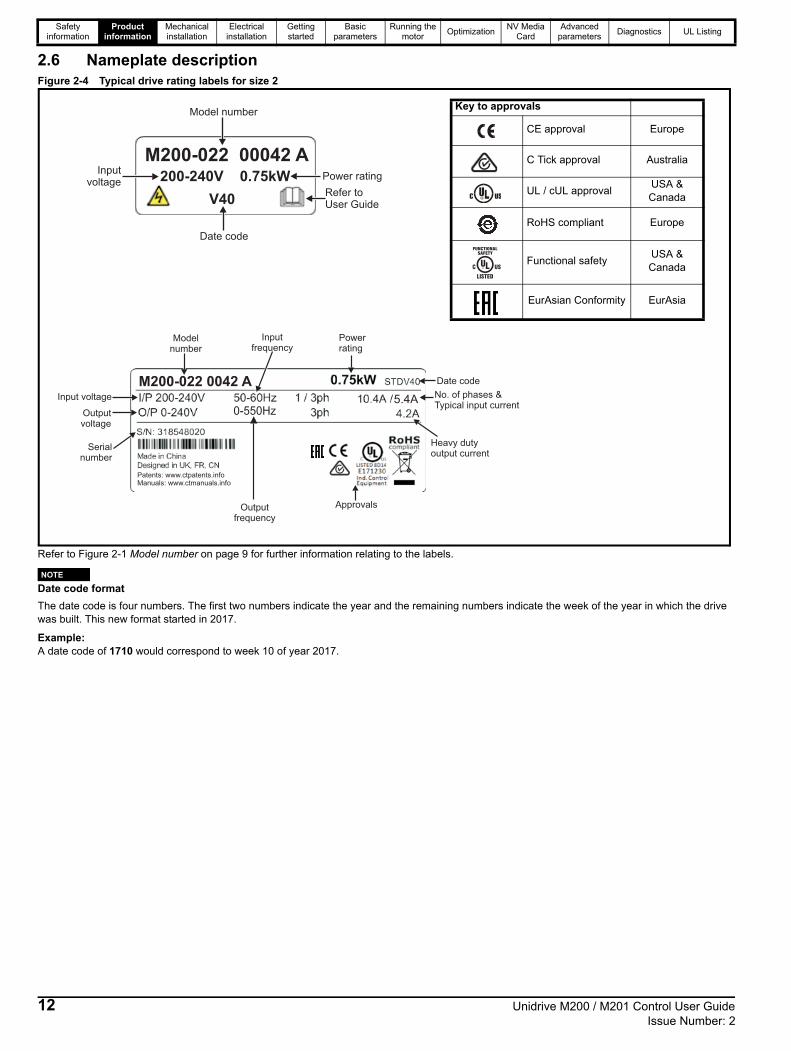
2.6 Nameplate descriptionFigure 2-4 Typical drive rating labels for size 2
Refer to Figure 2-1 Model number on page 9 for further information relating to the labels.
Date code format
The date code is four numbers. The first two numbers indicate the year and the remaining numbers indicate the week of the year in which the drive was built. This new format started in 2017.
Example:A date code of 1710 would correspond to week 10 of year 2017.
Model number
Refer toUser Guide
Date code
Inputvoltage
Power rating
M200-022 00042 A200-240V 0.75kW
V40
Modelnumber
Input voltage
Outputvoltage
Serialnumber
Inputfrequency
Powerrating
Date code
No. of phases &Typical input current
Heavy dutyoutput current
Approvals
M200-022 0042 A
5.4A
Patents: www.ctpatents.infoManuals: www.ctmanuals.info
0-550Hz
Outputfrequency
Key to approvals
CE approval Europe
C Tick approval Australia
UL / cUL approvalUSA & Canada
RoHS compliant Europe
Functional safetyUSA & Canada
EurAsian Conformity EurAsia
R
NOTE
12 Unidrive M200 / M201 Control User Guide Issue Number: 2

Safety information
Product information
Mechanical installation
Electrical installation
Getting started
Basic parameters
Running the motor
OptimizationNV Media
CardOnboard
PLCAdvanced
parametersDiagnostics UL Listing
2.7 OptionsFigure 2-5 Options available with the drive
1. AI-485 adaptor2. Option module (SI)3. CT USB comms cable4. Remote mountable LCD keypad5. AI-Backup adaptor module
1
2
4
5
3
Unidrive M200 / M201 Control User Guide 13Issue Number: 2

Safety information
Product information
Mechanical installation
Electrical installation
Getting started
Basic parameters
Running the motor
OptimizationNV Media
CardAdvanced
parametersDiagnostics UL Listing
Table 2-1 System Integration Option module identification
Table 2-2 Adaptor Interface (AI) option module identification
Table 2-3 Keypad identification
Type Option module Color Name Further details
Fieldbus
Purple SI-PROFIBUSProfibus optionPROFIBUS adaptor for communications with the drive
MediumGrey
SI-DeviceNetDeviceNet optionDeviceNet adaptor for communications with the drive
Light Grey SI-CANopenCANopen optionCANopen adaptor for communications with the drive
Yellow Green
SI-PROFINET V2PROFINET V2 optionPROFINET V2 adapter for communications with the drive
Beige SI-Ethernet
External Ethernet module that supports EtherNet/IP, Modbus TCP/IP and RTMoE. The module can be used to provide global connectivity and integration with IT network technologies, such as wireless networking
Brown Red SI-EtherCATEtherCAT optionEtherCAT adapter for communications with the drive
Automation(I/O expansion)
Orange SI-I/O
Extended I/OIncreases the I/O capability by adding the following combinations:• Digital I/O• Digital Inputs• Analog Inputs (differential or single ended)• Relays
Type Option module Name Further details
Communications
AI-485 adaptorEIA 485 serial communications optionProvides a EIA 485 serial communications interface via an RJ45 connector or alternative screw terminals.
AI-485 24V adaptor
EIA 485 serial communications optionProvides a EIA 485 serial communications interface via an RJ45 connector or alternative screw terminals. It also provides a 24 V Backup supply input.
Backup
AI-Backup adaptor+24 V Backup and SD card interfaceProvides a +24 V Backup supply input and SD card interface.
AI-Smart adaptor+24 V Backup and SD card interfaceSupplied with 4 GB SD Card for parameter copying and an input for 24 V Backup.
Type Keypad Name Further Details
Keypad
Remote-KeypadRemote LCD keypad optionRemote Keypad with a LCD display
Remote-Keypad RTCRemote LCD keypad optionRemote Keypad with a LCD display and real time clock
14 Unidrive M200 / M201 Control User Guide Issue Number: 2

Safety information
Product information
Mechanical installation
Electrical installation
Getting started
Basic parameters
Running the motor
OptimizationNV Media
CardOnboard
PLCAdvanced
parametersDiagnostics UL Listing
3 Mechanical installation
3.1 Installing / removing options
Figure 3-1 Installation of an SI option module (size 2 to 4)
Installing the option module
• With the option module tilted slightly backwards, align and locate the two holes in the rear of the option module onto the two tabs (1) on the drive.• Press the option module onto the drive as shown in (2) until the connector mates with the drive, ensuring that the tab (3) retains the option module
in place.
Check that the option module is securely located on the drive. Always ensure that the terminal cover is always replaced before use as this ensures that the option module is firmly secured.
Figure 3-2 Removing the SI-Option module (size 2 to 4)
• Press down on the tab (1) to release the option module from the drive housing as shown.• Tilt the option module slightly towards you and pull away from the drive housing (2).
Power down the drive before installing / removing the SI option module. Failure to do so may result in damage to the product.
CAUTION
3
2
1
NOTE
1
2
Unidrive M200 / M201 Control User Guide 15Issue Number: 2
Safety information
Product information
Mechanical installation
Electrical installation
Getting started
Basic parameters
Running the motor
OptimizationNV Media
CardOnboard
PLCAdvanced
parametersDiagnostics UL Listing
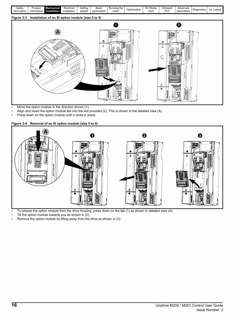
Figure 3-3 Installation of an SI option module (size 5 to 9)
• Move the option module in the direction shown (1).• Align and insert the option module tab into the slot provided (2), This is shown in the detailed view (A).• Press down on the option module until it clicks in place.
Figure 3-4 Removal of an SI option module (size 5 to 9)
• To release the option module from the drive housing, press down on the tab (1) as shown in detailed view (A).• Tilt the option module towards you as shown in (2).• Remove the option module by lifting away from the drive as shown in (3).
A
1 2
1 2 3A
16 Unidrive M200 / M201 Control User Guide Issue Number: 2

Safety information
Product information
Mechanical installation
Electrical installation
Getting started
Basic parameters
Running the motor
OptimizationNV Media
CardOnboard
PLCAdvanced
parametersDiagnostics UL Listing
Figure 3-5 Installing the AI-485 / AI-Backup Adaptor to the drive (AI-485 Adaptor shown)
• Identify the two plastic fingers on the underside of the AI-485 / AI-Backup Adaptor (1) - then insert the two fingers into the corresponding slots in the spring-loaded sliding cover on the top of the drive.
• Hold the adaptor firmly and push the spring loaded protective cover towards the back of the drive to expose the connector block (2) below.• Press the adaptor downwards (3) until the adaptor connector locates into the drive connection below.
Figure 3-6 Removal of the AI-485 / AI-Backup Adaptor adaptor (AI-485 Adaptor shown)
• To remove the AI-485 / AI-Backup Adaptor, pull it up away from the drive in the direction shown (1)
1
3
2
Unidrive M200 / M201 Control User Guide 17Issue Number: 2

Safety information
Product information
Mechanical installation
Electrical installation
Getting started
Basic parameters
Running the motor
OptimizationNV Media
CardOnboard
PLCAdvanced
parametersDiagnostics UL Listing
3.2 Real time clock battery replacementThose keypads which have the real time clock feature contain a battery to ensure the clock works when the drive is powered down. The battery has a long life time but if the battery needs to be replaced or removed, follow the instructions below.
Low battery voltage is indicated by low battery symbol on the keypad display.
Figure 3-7 Remote Keypad RTC (rear view)
Figure 3-7 above illustrates the rear view of the Remote Keypad RTC.
1. To remove the battery cover insert a flat head screwdriver into the slot as shown (1), push and turn anti-clockwise until the battery cover is released.
2. Replace the battery (the battery type is: CR2032).3. Reverse point 1 above to replace battery cover.
Ensure the battery is disposed of correctly.NOTE
18 Unidrive M200 / M201 Control User Guide Issue Number: 2

Safety information
Product information
Mechanical installation
Electrical installation
Getting started
Basic parameters
Running the motor
OptimizationNV Media
CardOnboard
PLCAdvanced
parametersDiagnostics UL Listing
4 Electrical installation
4.1 24 Vdc supplyThe 24 Vdc supply connected to the +24 V supply terminals on the AI-Backup adaptor provides the following functions:
• It can be used as a back-up power supply to keep the control circuits of the drive powered up when the line power supply is removed. This allows any fieldbus modules or serial communications to continue to operate. If the line power supply is re-applied, then the normal operation can carry on after the drive automatically re-initializes the power board parameters.
• It can be used to clone or load parameters in order to pre-configure drives when the line power supply is not available. The keypad can be used to setup parameters if required. However, the drive will be in the Under Voltage state unless the line power supply is enabled, therefore diagnostics may not be possible. (Power down save parameters are not saved when using the 24 V back-up power supply input).
The working voltage range of the 24 V back-up power supply is as follows:
Minimum and maximum voltage values include ripple and noise. Ripple and noise values must not exceed 5 %.
Figure 4-1 Location of the 24 Vdc power supply connection on the AI-Backup adaptor
The 24 Vdc Backup supply can be used on all frame sizes.
4.2 Communication connectionsInstalling an AI-485 Adaptor provides the drive with a 2 wire EIA 485 serial communications interface. This enables the drive set-up, operation and monitoring to be carried out with a PC or controller as required.
Figure 4-2 Location of the AI-485 Adaptor option
4.2.1 EIA 485 serial communicationsThe drive only supports Modbus RTU protocol. See Table 4-1 for the connection details.
Standard Ethernet cables must not be used when connecting drives on a EIA 485 network as they do not have the correct twisted pairs for the pinout of the serial comms port.
Table 4-1 Serial communication port pin-outs (RJ45)
Minimum number of connections are 2, 3, 7 and shield.
Table 4-2 Serial communication port pin-outs (screw terminal block)
NThe connections on the RJ45 connector and terminal block are in parallel.
0 V0 V (connected internally to 0V common - Control terminal 1)
+ 24 V + 24 V Backup supply input
Nominal operating voltage 24.0 Vdc
Minimum continuous operating voltage 19.2 V
Maximum continuous operating voltage 30.0 V
Minimum start up voltage 12.0 V
Minimum power supply requirement at 24 V 20 W
Maximum power supply continuous current 3 A
Recommended fuse 1 A, 50 Vdc
NOTE
Pin Function
1 120 Termination resistor
2 RX TX
3 0 V
4 +24 V (100 mA) output
5 Not connected
6 TX enable
7 RX\ TX\
8 RX\ TX\ (if termination resistors are required, link to pin 1)
Pin Function
1 0 V
2 RX\ TX\ (if termination resistor required, link to pin 4)
3 RX TX
4 120 Termination resistor
5 TX Enable
6 +24 V (100 mA) output
8 11 2 3 4 5 6
NOTE
NOTE
Unidrive M200 / M201 Control User Guide 19Issue Number: 2

Safety information
Product information
Mechanical installation
Electrical installation
Getting started
Basic parameters
Running the motor
OptimizationNV Media
CardOnboard
PLCAdvanced
parametersDiagnostics UL Listing
4.2.2 Isolation of the EIA 485 serial communication port
The serial communication port is single insulated and meets the requirements for ELV.
An isolated serial communications lead has been designed to connect the drive to IT equipment (such as laptop computers), and is available from the supplier of the drive. See below for details:
Table 4-3 Isolated serial comms lead details
The “isolated serial communications” lead has reinforced insulation as defined in IEC60950 for altitudes up to 3,000 m.
4.3 Control connections4.3.1 GeneralTable 4-4 The control connections consist of:
Key:
All analog terminal functions can be programmed in menu 7.
All digital terminal functions (including the relay) can be programmed in menu 8.
NAny signal cables which are carried inside the motor cable (i.e. motor thermistor, motor brake) will pick up large pulse currents via the cable capacitance. The shield of these signal cables must be connected to ground close to the point of exit of the motor cable, to avoid this noise current spreading through the control system.
Figure 4-3 Default terminal functions
When using the communications port with a personal computer or centralised controller e.g. PLC, an isolation device must be included with a rated voltage at least equal to the drive supply voltage. Ensure that the correct fuses are installed at the drive input, and that the drive is connected to the correct supply voltage.If a serial communications converter other than the CT Comms cable is used to connect to other circuits classified as Safety Extra Low Voltage (SELV) (e.g. to a personal computer), then a safety isolating barrier must be included to maintain the SELV classification.
Part number Description
4500-0096 CT USB Comms cable
Function QtyControl parameters
availableTerminal number
Single ended analog input
2Mode, offset, invert, scaling, destination
2, 5
Analog output 1 Source, mode, scaling, 7
Digital input 5 Destination, invert5, 11, 12,
13, 14
Digital input / output 1Input / output mode select, destination / source, invert
10
Frequency input 1Maximum reference, input limit, scaling, destination
14
PWM or frequency output
1Source, scaling, maximum output frequency, mode
10
Motor thermistor input 1Mode, type, trip threshold, reset threshold
14
Relay 1 Source, invert 41, 42
Drive enable 1 11
+10 V User output 1 4
+24 V User output 1 9
0V common 1 1
Destination parameter:Indicates the parameter which is being controlled by the terminal / function
Source parameter:Indicates the parameter being output by the terminal
Mode parameter:
Analog - indicates the mode of operation of the terminal, i.e. voltage 0-10 V, current 4-20 mA etc. Digital - indicates the mode of operation of the terminal, (the Drive Enable terminal is fixed in positive logic).
WARNING
The control circuits are isolated from the power circuits in the drive by basic insulation (single insulation) only. The installer must ensure that the external control circuits are insulated from human contact by at least one layer of insulation (supplementary insulation) rated for use at the AC supply voltage.
If the control circuits are to be connected to other circuits classified as Safety Extra Low Voltage (SELV) (e.g. to a personal computer), an additional isolating barrier must be included in order to maintain the SELV classification.
If any of the digital inputs (including the drive enable input) are connected in parallel with an inductive load (i.e. contactor or motor brake) then suitable suppression (i.e. diode or varistor) should be used on the coil of the load. If no suppression is used then over voltage spikes can cause damage to the digital inputs and outputs on the drive.
WARNING
WARNING
CAUTION
NOTE
1 14 41 42
12
13
At zero frequency
Frequency
Run forward
Run reverse
Analog input 1/input 2 select
41
42
Relay(over-voltagecategory II)
Drive OK
Analogfrequency
reference 1
Analogfrequency
reference 2
1
4
5
7
9
10
11
2
0V common
Drive enable
+10 V
+24 V
Analog input 1 select
Analog input 2 select
14
20 Unidrive M200 / M201 Control User Guide Issue Number: 2

Safety information
Product information
Mechanical installation
Electrical installation
Getting started
Basic parameters
Running the motor
OptimizationNV Media
CardOnboard
PLCAdvanced
parametersDiagnostics UL Listing
4.3.2 Control terminal specification
1 0V common
Function Common connection for all external devices
2 Analog input 1
Default function Frequency reference
Type of inputUnipolar single-ended analog voltage or unipolar current
Mode controlled by… Pr 07.007
Operating in voltage mode (default)
Full scale voltage range 0 V to +10 V ±3 %
Maximum offset ±30 mV
Absolute maximum voltage range -18 V to +30 V relative to 0 V
Input resistance 100 kΩ
Operating in current mode
Current ranges0 to 20 mA ±5 %, 20 to 0 mA ±5 %,4 to 20 mA ±5 %, 20 to 4 mA ±5 %
Maximum offset 250 µA
Absolute maximum voltage (reverse bias)
-18 V to +30 V relative to 0 V
Absolute maximum current 25 mA
Equivalent input resistance 165 Ω
Common to all modes
Resolution 11 bits
Sample rate 4 ms
4 +10 V user output
Default function Supply for external analog devices
Nominal voltage 10.2 V
Voltage tolerance ±3 %
Maximum output current 5 mA
5 Analog input 2
Default function Frequency reference
Type of inputUnipolar single-ended analog voltage or positive logic only digital input
Mode controlled by.... Pr 07.011
Operating in voltage mode (default)
Full scale voltage range 0 V to +10 V ±3 %
Maximum offset ±30 mV
Absolute maximum voltage range -18 V to +30 V relative to 0 V
Input resistance 100 kΩ
Resolution 11 bits
Sample rate 4 ms
Operating in digital mode
Absolute maximum voltage range -18 V to +30 V relative to 0 V
Impedance 6.8 kΩ
Input threshold 10 V ±0.8 V (IEC 61131-2)
Sample rate1 ms when routed to destinations Pr 06.035 or Pr 06.036, otherwise 4 ms.
7 Analog output 1
Default function Frequency output
Type of output Unipolar single-ended analog voltage
Voltage range +10 V
Maximum offset 15 mV
Load resistance ≥ 2 kΩ
Protection Short circuit relative to 0 V
Resolution 0.1 %
Sample rate 4 ms
9 +24 V user output
Default function Supply for external digital devices
Voltage tolerance ±20 %
Maximum output current 100 mA
Protection Current limit and trip
10 Digital I/O 1
Default function AT ZERO FREQUENCY output
Type
Positive logic digital input, positive logic voltage source output.PWM or frequency output modes can be selected.
Input / output mode controlled by … Pr 08.031
Operating as in input
Absolute maximum applied voltage range
-8 V to +30 V relative to 0 V
Impedance 6.8 kΩ
Input threshold 10 V ±0.8 V (IEC 61131-2)
Operating as an output
Nominal maximum output current 50 mA
Maximum output current 100 mA (total including +24 Vout)
Common to all modes
Voltage range 0 V to +24 V
Sample rate1 ms when routed to destinations Pr 06.035 or Pr 06.036, otherwise 4 ms
11 Digital Input 2
12 Digital Input 3
13 Digital Input 4
Terminal 11 default function DRIVE ENABLE input
Terminal 12 default function RUN FORWARD input
Terminal 13 default function RUN REVERSE input
Type Positive logic only digital inputs
Voltage range 0 V to +24 V
Absolute maximum applied voltage range
-18 V to +30 V relative to 0 V
Impedance 6.8 kΩ
Input threshold 10 V ±0.8 V (IEC 61131-2)
Sample rate1 ms when routed to destinations Pr 06.035 or Pr 06.036, otherwise 4 ms.
Unidrive M200 / M201 Control User Guide 21Issue Number: 2

Safety information
Product information
Mechanical installation
Electrical installation
Getting started
Basic parameters
Running the motor
OptimizationNV Media
CardOnboard
PLCAdvanced
parametersDiagnostics UL Listing
14 Digital Input 5
Terminal 14 default function Analog INPUT 1 / INPUT 2 select
Type
Positive logic only digital input. Frequency input or motor thermistor input (bias for DIN44081 ptc, KTY84, PT1000, PT2000 and other types) mode can be selected.
Voltage range 0 V to +24 V
Absolute maximum applied voltage range
-18 V to +30 V relative to 0 V
Impedance 6.8 kΩ
Input threshold 10 V ±0.8 V (IEC 61131-2)
Sample rate1 ms when routed to destinations Pr 06.035 or Pr 06.036, otherwise 4 ms.
41Relay contacts
42
Default function Drive OK indicator
Contact voltage rating 240 Vac, Installation over-voltage category II
Contact maximum current rating2 A AC 240 V4 A DC 30 V resistive load0.5 A DC 30 V inductive load (L/R = 40 ms)
Contact minimum recommended rating
12 V 100 mA
Contact type Normally open
Default contact condition Closed when power applied and drive OK
Update rate 1 ms
To prevent the risk of a fire hazard in the event of a fault, a fuse or other over-current protection must be installed in the relay circuit.
WARNING
22 Unidrive M200 / M201 Control User Guide Issue Number: 2

Safety information
Product information
Mechanical installation
Electrical installation
Getting started
Basic parameters
Running the motor
OptimizationNV Media
CardOnboard
PLCAdvanced
parametersDiagnostics UL Listing
5 Getting startedThis chapter introduces the user interfaces, menu structure and security levels of the drive.
5.1 Understanding the display5.1.1 KeypadThe keypad display consists of a 6 digit LED display. The display shows the drive status or the menu and parameter number currently being edited.
The option module Unidrive menu (S.mm.ppp) is only displayed if the option module is installed. Where S signifies the option module slot number and the mm.ppp signifies the menu and parameter number of the option module’s internal menus and parameter.
The display also includes LED indicators showing units and status as shown in Figure 5-1. When the drive is powered up, the display will show the power up parameter defined by Parameter Displayed At Power-Up (11.022).
The values in the Status Mode Parameters (Pr 22 and Pr 23) shown on the display when the drive is running, can be toggled by using the escape button.
Figure 5-1 Unidrive M200 keypad detail
1. Escape button2. Down button3. Start button (green)4. Stop / Reset button (red)5. Up button6. Enter button7. Run forward indicator8. Run reverse indicator9. Keypad reference indicator10. Unit indicators
Figure 5-2 Unidrive M201 keypad detail
1. Run forward indicator2. Unit indicators3. Speed reference potentiometer4. Keypad reference indicator5. Run reverse indicator
The red stop button is also used to reset the drive.
The parameter value is correctly displayed on the keypad display as shown in Table 5-1.
On the Unidrive M201, the speed reference potentiometer is used to adjust the keypad reference.
Table 5-1 Keypad display formats
*Alternate display
5.2 Keypad operation5.2.1 Control buttonsThe keypad consists of:
• Up and down button - Used to navigate the parameter structure and change parameter values.
• Enter button - Used to change between parameter edit and view mode as well as entering data. This button can also be used to select between slot menu and parameter display.
• Escape button - Used to exit from parameter edit or view mode. In parameter edit mode, if parameter values are edited and the escape button pressed, the parameter value will be restored to the value it had on entry to edit mode.
• Start button - Used to provide a 'Run' command if keypad mode is selected.
• Stop / Reset button - Used to reset the drive. In keypad mode can be used for 'Stop'.
NOTE
10
7
8
6
5
4
9
1
2
3
Display formats Value
Standard 100.99
Date 31.12.11 or 12.31.11
Time 12.34.56
Character ABCDEF
Binary 5
IP Address 192.168 88.1*
MAC Address 01.02.03 04.05.06*
Version number 01.23.45
1
3
2
5
V A Hz rpm %1
4
NOTE
Unidrive M200 / M201 Control User Guide 23Issue Number: 2

Safety information
Product information
Mechanical installation
Electrical installation
Getting started
Basic parameters
Running the motor
OptimizationNV Media
CardOnboard
PLCAdvanced
parametersDiagnostics UL Listing
Figure 5-3 Display modes
The up and down buttons can only be used to move between menus if Pr 10 has been set to show 'ALL'. Refer to section 5.9 Parameter access level and security on page 27.
To return to Status Mode,
press button
To return to Parameter View Mode,press button
Press or to select parameter
StatusMode
To enter Parameter View Mode,press button
ParameterView Mode
Pr 10
Pr 01
0.00
0.00
To view parameter valuepress button
To enter Edit Mode,press button
0.00
Edit Mode (edited digit flashes)
Holding or increases or decreases value
ParameterValue View
To return to Parameter Value Viewpress button to keep the new value
press button to ignore new value and
return the parameter to the pre-edited value
NOTE
24 Unidrive M200 / M201 Control User Guide Issue Number: 2

Safety information
Product information
Mechanical installation
Electrical installation
Getting started
Basic parameters
Running the motor
OptimizationNV Media
CardOnboard
PLCAdvanced
parametersDiagnostics UL Listing
Figure 5-4 Mode examples
1 Parameter view mode: Read write or Read only
2 Status mode: Drive OK statusIf the drive is ok and the parameters are not being edited or viewed, the display will show one of the following:
inh', 'rdy' or status mode parameter value.
3 Status mode: Trip statusWhen the drive is in trip condition, the display will indicate that the drive has tripped and the display will show the trip code. For further information regarding trip codes, refer to section 12.4 Trips, Sub-trip numbers on page 130.
4 Status mode: Alarm statusDuring an 'alarm' condition the display flashes between the drive status parameter value and the alarm.
When changing the values of parameters, make a note of the new values in case they need to be entered again.
New parameter values must be saved to ensure that the new values apply after the drive has been power cycled. Refer to section 5.7 Saving parameters on page 26.
5.3 Menu structureThe drive parameter structure consists of menus and parameters.
The drive initially powers up so that only Menu 0 can be viewed. The up and down arrow buttons are used to navigate between parameters and once Pr 10 has been set to 'All' the up and down buttons are used to navigate between menus.
For further information refer to section 5.9 Parameter access level and security on page 27.
The menus and parameters rollover in both directions i.e. if the last parameter is displayed, a further press will cause the display to rollover and show the first parameter.
When changing between menus, the drive remembers which parameter was last viewed in a particular menu and thus displays that parameter.
5.4 Menu 0Menu 0 is used to bring together various commonly used parameters for basic easy set up of the drive. The parameters displayed in Menu 0 can be configured in Menu 22.Appropriate parameters are copied from the advanced menus into Menu 0 and thus exist in both locations.For further information, refer to Chapter 6 Basic parameters on page 29.
Figure 5-5 Menu 0 copying
Do not change parameter values without careful consideration; incorrect values may cause damage or a safety hazard.
3 4
1 2
WARNING
NOTE
NOTE
Menu 0
040506
Menu 2
02.021
Menu 11
11.034
Menu 5
05.007
10.0
AV
4.1
AV
4.1
10.0
Unidrive M200 / M201 Control User Guide 25Issue Number: 2

Safety information
Product information
Mechanical installation
Electrical installation
Getting started
Basic parameters
Running the motor
OptimizationNV Media
CardOnboard
PLCAdvanced
parametersDiagnostics UL Listing
5.5 Advanced menus The advanced menus consist of groups or parameters appropriate to a specific function or feature of the drive. Menus 0 to 24 can be viewed on the Keypad.
The option module menu (1.mm.ppp) is only displayed if the option module is installed. Where 1 signifies the option module slot number and the mm.ppp signifies the menu and parameter number of the option module’s internal menus and parameters.
Table 5-2 Advanced menu descriptions
* Only displayed when the option module is installed.
5.5.1 Display messagesThe following tables indicate the various possible mnemonics which can be displayed by the drive and their meaning.
Table 5-3 Status indications
5.5.2 Alarm indicationsAn alarm is an indication given on the display by alternating the alarm string with the drive status string on the display. Alarms strings are not displayed when a parameter is being edited.
Table 5-4 Alarm indications
5.6 Changing the operating modeProcedureUse the following procedure only if a different operating mode is required:
1. Ensure the drive is not enabled, i.e. drive is in inhibit or under voltage state.
2. Change the setting of Pr 79 as follows:
The figures in the second column apply when serial communications are used.
When the operating mode is changed, a parameter save is carried out.
3. Either:
Press the red reset button
Carry out a drive reset through serial communications by setting Pr 10.038 to 100.
5.7 Saving parametersWhen changing a parameter in Menu 0, the new value is saved when
pressing the Enter button to return to parameter view mode
from parameter edit mode.
If parameters have been changed in the advanced menus, then the change will not be saved automatically. A save function must be carried out.
Procedure1. Select ‘Save' in Pr 00 or Pr mm.000 (alternatively enter a value of
1001 in Pr 00 or Pr mm.000)2. Either:
• Press the red reset button
• Carry out a drive reset through serial communications by setting Pr 10.038 to 100
Menu Description
0Commonly used basic set up parameters for quick / easy programming
1 Frequency reference
2 Ramps
3 Frequency control
4 Torque and current control
5 Motor control
6 Sequencer and clock
7 Analog I/O
8 Digital I/O
9 Programmable logic, motorized pot, binary sum, timers
10 Status and trips
11 Drive set-up and identification, serial communications
12 Threshold detectors and variable selectors
14 User PID controller
15 Option module slot 1 set-up menu
18 General option module application menu 1
20 General option module application menu 2
21 Second motor parameters
22 Menu 0 set-up
24 Option module slot 1 application menu
Slot 1 Slot 1 option menus*
String DescriptionDrive
output stage
inh
The drive is inhibited and cannot be run. The Drive Enable signal is not applied to the drive enable terminal or Pr 06.015 is set to 0. The other conditions that can prevent the drive from enabling are shown as bits in Enable Conditions (06.010)
Disabled
rdyThe drive is ready to run. The drive enable is active, but the drive inverter is not active because the final drive run is not active
Disabled
Stop The drive is stopped / holding zero speed. Enabled
S.Loss Supply loss condition has been detected Enabled
dc inj The drive is applying dc injection braking Enabled
ErThe drive has tripped and no longer controlling the motor. The trip code appears on the display.
Disabled
UVThe drive is in the under voltage state either in low voltage or high voltage mode.
Disabled
HEAt The motor pre-heat function is active. Enabled
Alarm string Description
br.resBrake resistor overload. Braking Resistor Thermal Accumulator (10.039) in the drive has reached 75.0 % of the value at which the drive will trip.
OV.LdMotor Protection Accumulator (04.019) in the drive has reached 75.0 % of the value at which the drive will trip and the load on the drive is >100 %.
d.OV.LdDrive over temperature. Percentage Of Drive Thermal Trip Level (07.036) in the drive is greater than 90 %.
tuningThe autotune procedure has been initialized and an autotune in progress.
LSLimit switch active. Indicates that a limit switch is active and that is causing the motor to be stopped.
Opt.AI Option slot alarm.
Lo.AC Low voltage mode. See Low AC Alarm (10.107).
I.AC.LtCurrent limit active. See Current Limit Active (10.009).
24.LoSt24 V backup not present. See 24V Alarm Loss Enable (11.098).
Pr 79 setting Operating mode
1 Open-loop
2 RFC-A
NOTE
26 Unidrive M200 / M201 Control User Guide Issue Number: 2

Safety information
Product information
Mechanical installation
Electrical installation
Getting started
Basic parameters
Running the motor
OptimizationNV Media
CardOnboard
PLCAdvanced
parametersDiagnostics UL Listing
5.8 Restoring parameter defaultsRestoring parameter defaults by this method saves the default values in the drives memory. User security status (Pr 10) and User security code (Pr 25) are not affected by this procedure).
Procedure1. Ensure the drive is not enabled, i.e. drive is in inhibit or under
voltage state.2. Select 'Def.50’ or 'Def.60' in Pr 00 or Pr mm.000. (alternatively, enter
1233 (50 Hz settings) or 1244 (60 Hz settings) in Pr 00 or Pr mm.000).
3. Either:
• Press the red reset button
• Carry out a drive reset through serial communications by setting Pr 10.038 to 100
5.9 Parameter access level and securityThe parameter access level determines whether the user has access to Menu 0 only or to all the advanced menus (Menus 1 to 24) in addition to Menu 0.
The User Security determines whether the access to the user is read only or read write.
Both the User Security and Parameter Access Level can operate independently of each other as shown in Table 5-5.
Table 5-5 Parameter access level and security
The default settings of the drive are Parameter Access Level LEVEL.1 and user Security Open i.e. read / write access to Menu 0 with the advanced menus not visible.
5.9.1 User Security Level / Access LevelThe drive provides a number of different levels of security that can be set by the user via User Security Status (Pr 10); these are shown in the table below.
5.9.2 Changing the User Security Level /Access Level
The security level is determined by the setting of Pr 10 or Pr 11.044. The Security Level can be changed through the keypad even if the User Security Code has been set.
5.9.3 User Security CodeThe User Security Code, when set, prevents write access to any of the parameters in any menu.
Setting User Security Code
Enter a value between 1 and 9999 in Pr 25 and press the
button; the security code has now been set to this value. In order to activate the security, the Security level must be set to desired level in Pr 10. When the drive is reset, the security code will have been activated and the drive returns to LEVEL.1. The value of Pr 25 will return to 0 in order to hide the security code.
Unlocking User Security CodeSelect a parameter that need to be edited and press the button,
the display will now show ‘Co’. Use the arrow buttons to set the security
code and press the button. With the correct security code
entered, the display will revert to the parameter selected in edit mode.
If an incorrect security code is entered, the following message ‘Co.Err’ is displayed, and the display will revert to parameter view mode.
Disabling User SecurityUnlock the previously set security code as detailed above. Set Pr 25 to 0
and press the button. The User Security has now been
disabled, and will not have to be unlocked each time the drive is powered up to allow read / write access to the parameters.
5.10 Displaying parameters with non-default values only
By selecting 'diff.d' in Pr 00 (Alternatively, enter 12000 in Pr 00), the only parameters that will be visible to the user will be those containing a non-default value. This function does not require a drive reset to become active. In order to deactivate this function, return to
Pr 00 and select 'none' (alternatively enter a value of 0). Please note that this function can be affected by the access level enabled, refer to section 5.9 Parameter access level and security on page 27 for further information regarding access level.
User security status (Pr 10)
Access level
Menu 0 statusAdvanced menu
status
0 LEVEL.1 RW Not visible
1 LEVEL.2 RW Not visible
2 ALL RW RW
3 StAtUS RW Not visible
4 no.Acc RW Not visible
User Security Status (Pr 10)
Description
LEVEL.1 (0) Access to first 10 parameters in Menu 0 only.
LEVEL.2 (1) Access to all parameters in Menu 0.
ALL (2) Access to all menus.
StAtUS (3)The keypad remains in status mode and only first 10 parameters in Menu 0 can be viewed or edited.
no.Acc (4)
The keypad remains in status mode and only first 10 parameters in Menu 0 can be viewed or edited. Drive parameters cannot be accessed via a comms interface.
Unidrive M200 / M201 Control User Guide 27Issue Number: 2

Safety information
Product information
Mechanical installation
Electrical installation
Getting started
Basic parameters
Running the motor
OptimizationNV Media
CardOnboard
PLCAdvanced
parametersDiagnostics UL Listing
5.11 Displaying destination parameters onlyBy selecting 'dest' in Pr 00 (Alternatively enter 12001 in Pr 00), the only parameters that will be visible to the user will be destination parameters. This function does not require a drive reset to become active. In order to deactivate this function, return to Pr 00 and select 'none' (alternatively enter a value of 0).
Please note that this function can be affected by the access level enabled, refer to section 5.9 Parameter access level and security on page 27 for further information regarding access level.
5.12 CommunicationsInstalling an AI-485 Adaptor provides the drive with a 2 wire EIA 485 serial communications interface. This enables the drive set-up, operation and monitoring to be carried out with a PC or controller as required.
5.12.1 EIA 485 Serial communicationsCommunication is via the RJ45 connector or screw terminals (parallel connection). The drive only supports Modbus RTU protocol.
The communications port applies a 1.25 unit load to the communications network.
USB to EIA 485 CommunicationsAn external USB hardware interface such as a PC cannot be used directly with the 2-wire EIA 485 interface of the drive. Therefore a suitable converter is required.
A suitable USB to EIA 485 isolated converter is available from Control Techniques as follows:
• CT USB Comms cable (CT Part No. 4500-0096)
When using the above converter or any other suitable converter with the drive, it is recommended that no terminating resistors be connected on the network. It may be necessary to 'link out' the terminating resistor within the converter depending on which type is used. The information on how to link out the terminating resistor will normally be contained in the user information supplied with the converter.
Serial communications set-up parametersThe following parameters need to be set according to the system requirements.
Serial communications set-up parameters
Serial Mode (11.024)
8 2 NP (0), 8 1 NP (1), 8 1 EP (2), 8 1 OP (3), 8 2 NP M (4), 8 1 NP M (5), 8 1 EP M (6), 8 1 OP M (7), 7 1 EP (8), 7 1 OP (9), 7 1 EP M (10), 7 1 OP M (11)
The drive only supports the Modbus RTU protocol and is always a slave. This parameter defines the supported data formats used by the EIA 485 comms port (if installed) on the drive. This parameter can be changed via the drive keypad, via a option module or via the comms interface itself.
Serial Baud Rate (Pr 43)
600 (1), 1200 (2), 2400 (3), 4800 (4), 9600 (5), 19200 (6), 38400 (7), 57600(8), 76800(9), 115200 (10)
This parameter can be changed via the drive keypad, via a option module or via the comms interface itself. If it is changed via the comms interface, the response to the command uses the original baud rate. The master should wait at least 20 ms before sending a new message using the new baud rate.
Serial Address (Pr 44)
1 to 247 This parameter defines the serial address and an addresses between 1 and 247 are permitted.
Reset Serial
Communications (Pr 45)
Off (0) or On (1)When the above parameters are modified the changes do not have an immediate effect on the serial communication system. The new values are used after the next power up or if Reset Serial Communicationsis set to 1.
28 Unidrive M200 / M201 Control User Guide Issue Number: 2

Safety information
Product information
Mechanical installation
Electrical installation
Getting started
Basic parameters
Running the motor
OptimizationNV Media
CardOnboard
PLCAdvanced
parametersDiagnostics UL Listing
6 Basic parametersMenu 0 is used to bring together various commonly used parameters for basic easy set up of the drive. All the parameters in Menu 0 appear in other menus in the drive (denoted by …). Menu 22 can be used to configure the parameters in Menu 0.
Parameter ranges and Variable minimum/maximums:
Some parameters in the drive have a variable range with a variable minimum and a variable maximum value which is dependent on one of the
following:
• The settings of other parameters
• The drive rating
• The drive mode
• Combination of any of the above
For more information please see section 11.1 Parameter ranges and Variable minimum/maximums: on page 70.
6.1 Menu 0: Basic parameters
ParameterRange () Default ()
TypeOL RFC-A OL RFC-A
01 Minimum Speed 01.007 0.00 to Pr 02 Hz 0.00 Hz RW Num US
02 Maximum Speed 01.006 0.00 to 550.00 Hz50Hz default: 50.00 Hz60Hz default: 60.00 Hz
RW Num US
03 Acceleration Rate 1 02.011 0.0 to 32000.0 s / 100 Hz 5.0 s / 100 Hz RW Num US
04 Deceleration Rate 1 02.021 0.0 to 32000.0 s / 100 Hz 10.0 s / 100 Hz RW Num US
05 Drive Configuration 11.034AV (0), AI (1), AV.Pr (2), AI.Pr (3), PrESEt (4), PAd (5),
PAd.rEF (6), E.Pot (7), torquE (8), Pid (9) AV (0)* RW Txt PT US
06 Motor Rated Current 05.007 0.00 to Drive Rating A Maximum Heavy Duty Rating A RW Num RA US
07 Motor Rated Speed** 05.008 0.0 to 33000.0 rpm
50Hz default: 1500.0 rpm
60Hz default: 1800.0 rpm
50Hz default: 1450.0 rpm
60Hz default: 1750.0 rpm
RW Num US
08 Motor Rated Voltage 05.009 0 to 765 V
110V drive: 230 V200V drive: 230 V
400V drive 50 Hz: 400 V400V drive 60 Hz: 460 V
575V drive: 575 V690V drive: 690 V
RW Num RA US
09 Motor Rated Power Factor*** 05.010 0.00 to 1.00 0.85 RW Num RA US
10 User Security Status 11.044 LEVEL.1 (0), LEVEL.2 (1), ALL (2), StAtUS (3), no.Acc (4) LEVEL.1 (0) RW Num ND PT
11 Start/Stop Logic Select 06.004 0 to 6 0 RW Num US
15 Jog Reference 01.005 0.00 to 300.00 Hz 1.50 Hz RW Num US
16 Analog Input 1 Mode 07.0074-20.S (-6), 20-4.S (-5), 4-20.L (-4),
20-4.L (-3), 4-20.H (-2), 20-4.H (-1), 0-20 (0), 20-0 (1), 4-20.tr (2), 20-4.tr (3), 4-20 (4), 20-4 (5), Volt (6)
Volt (6) RW Txt US
17 Bipolar Reference Enable 01.010 Off (0) or On (1) Off (0) RW Bit US
18 Preset Reference 1 01.021 0.00 to Pr 02 Hz 0.00 Hz RW Num US
19 Preset Reference 2 01.022 0.00 to Pr 02 Hz 0.00 Hz RW Num US
20 Preset Reference 3 01.023 0.00 to Pr 02 Hz 0.00 Hz RW Num US
21 Preset Reference 4 01.024 0.00 to Pr 02 Hz 0.00 Hz RW Num US
22 Status Mode Parameter 2 11.019 0.000 to 30.999 4.020 RW Num PT US
23 Status Mode Parameter 1 11.018 0.000 to 30.999 2.001 RW Num PT US
24 Customer Defined Scaling 11.021 0.000 to 10.000 1.000 RW Num US
25 User Security Code 11.030 0 to 9999 0 RW Num ND PT US
27Power-up Keypad Control Mode Reference
01.051 Reset (0), Last (1), Preset (2) Reset (0) RW Txt US
28 Ramp Mode Select 02.004 Fast (0), Std (1), Std.bst (2), Fst.bst (3) Std (1) RW Txt US
29 Ramp Enable 02.002 Off (0) or On (1) On (1) RW Bit US
30 Parameter Cloning 11.042 NonE (0), rEAd (1), Prog (2), Auto (3), boot (4) NonE (0) RW Txt NC US
31 Stop Mode 06.001Coast (0), rp (1), rp.dc I (2), dc
I (3), td.dc I (4), dis (5)
Coast (0), rp (1), rp.dc I (2), dc I (3), td.dc I (4),
dis (5), No.rp (6)rp (1) RW Txt US
32Dynamic V to F Select 05.013 0 to 1 0 RW Num US
Flux Optimisation Select 05.013 0 to 1 0 RW Num US
33 Catch A Spinning Motor 06.009 dis (0), Enable (1), Fr.Only (2), Rv.Only (3) dis (0) RW Txt US
34 Digital Input 5 Select 08.035 Input (0), th.Sct (1), th (2), th.Notr (3), Fr (4) Input (0) RW Txt US
35 Digital Output 1 Control 08.091 0 to 21 0 RW Num US
Unidrive M200 / M201 Control User Guide 29Issue Number: 2
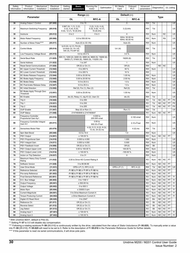
Safety information
Product information
Mechanical installation
Electrical installation
Getting started
Basic parameters
Running the motor
OptimizationNV Media
CardOnboard
PLCAdvanced
parametersDiagnostics UL Listing
* With Unidrive M201, default is PAd (5).** Setting Pr 07 to 0.0 will disable slip compensation.*** Following a rotating autotune Pr 09 05.010 is continuously written by the drive, calculated from the value of Stator Inductance (Pr 05.025). To manually enter a value into Pr 09 05.010, Pr 05.025 will need to be set to 0. Refer to the description of Pr 05.010 in the Parameter Reference Guide for further details.**** If this parameter is read via serial communications, it will show pole pairs.
36 Analog Output 1 Control 07.055 0 to 15 0 RW Txt US
37 Maximum Switching Frequency 05.0180.667 (0), 1 (1), 2 (2),
3 (3), 4 (4), 6 (5), 8 (6), 12 (7), 16 (8) kHz
2 (2), 3 (3), 4 (4), 6 (5), 8 (6), 12 (7),
16 (8) kHz3 (3) kHz RW Txt US
38 Autotune 05.012 0 to 2 0 to 3 0 RW Num NC US
39 Motor Rated Frequency 05.006 0.0 to 550.00 Hz50Hz: 50.00 Hz60Hz: 60.00 Hz
RW Num RA US
40 Number of Motor Poles**** 05.011 Auto (0) to 32 (16) Auto (0) RW Num US
41 Control Mode 05.014Ur.S (0), Ur (1), Fd (2),
Ur.Auto (3), Ur.I (4), SrE (5), Fd.tAP (6)
Ur.I (4) RW Txt US
42 Low Frequency Voltage Boost 05.015 0.0 to 25.0 % 3.0 % RW Num US
43 Serial Baud Rate 11.025600 (1), 1200 (2), 2400 (3), 4800 (4), 9600 (5), 19200 (6),
38400 (7), 57600 (8), 76800 (9), 115200 (10)19200 (6) RW Txt US
44 Serial Address 11.023 1 to 247 1 RW Num US
45 Reset Serial Communications 11.020 Off (0) or On (1) Off (0) RW ND NC
46 BC Upper Current Threshold 12.042 0 to 200 % 50 % RW Num US
47 BC Lower Current Threshold 12.043 0 to 200 % 10 % RW US
48 BC Brake Release Frequency 12.044 0.00 to 20.00 Hz 1.00 Hz RW Num US
49 BC Brake Apply Frequency 12.045 0.00 to 20.00 Hz 2.00 Hz RW Num US
50 BC Brake Delay 12.046 0.0 to 25.0 s 1.0 s RW Num US
51 BC Post-brake Release Delay 12.047 0.0 to 25.0 s 1.0 s RW Num US
53 BC Initial Direction 12.050 Ref (0), For (1), Rev (2) Ref (0) RW Txt US
54BC Brake Apply Through Zero Threshold
12.051 0.00 to 25.00 Hz 1.00 Hz RW Num US
55 BC Enable 12.041 dis (0), Relay (1), dig IO (2), User (3) dis (0) RW Txt US
56 Trip 0 10.020 0 to 255 RO Txt ND NC PT PS
57 Trip 1 10.021 0 to 255 RO Txt ND NC PT PS
58 Trip 2 10.022 0 to 255 RO Txt ND NC PT PS
59 OUP Enable 11.047 Stop (0) or Run (1) Run (1) RW Txt US
60 OUP Status 11.048 -2147483648 to 2147483647 RO Num ND NC PT
65Frequency Controller Proportional Gain Kp1
03.0100.000 to
200.000 s/rad0.100 s/rad RW Num US
66Frequency Controller Integral Gain Ki1
03.0110.00 to
655.35 s2/rad0.10 s2/rad RW Num US
67 Sensorless Mode Filter 03.0794 (0), 5 (1), 6 (2), 8 (3),
12 (4), 20 (5) ms4 (0) ms RW Txt US
69 Spin Start Boost 05.040 0.0 to 10.0 1.0 RW Num US
70 PID1 Output 14.001 ± 100.00 % RO Num ND NC PT
71 PID1 Proportional Gain 14.010 0.000 to 4.000 1.000 RW Num US
72 PID1 Integral Gain 14.011 0.000 to 4.000 0.500 RW Num US
73 PID1 Feedback Invert 14.006 Off (0) or On (1) Off (0) RW Bit US
74 PID1 Output Upper Limit 14.013 0.00 to 100.00 % 100.00 % RW Num US
75 PID1 Output Lower Limit 14.014 ± 100.00 % -100.00 % RW Num US
76 Action on Trip Detection 10.037 0 to 31 0 RW Num US
77Maximum Heavy Duty Current Rating
11.032 0.00 to Drive HD Current Rating A RO Num ND NC PT
78 Software Version 11.029 0 to 99.99.99 RO Num ND NC PT
79 User Drive Mode 11.031 OPEn.LP (1), RFC-A (2) OPEn.LP (1) RFC-A (2) RW Txt ND NC PT US
81 Reference Selected 01.001 -Pr 02 to Pr 02 or Pr 01 to Pr 02 Hz RO Num ND NC PT
82 Pre-ramp Reference 01.003 -Pr 02 to Pr 02 or Pr 01 to Pr 02 Hz RO Num ND NC PT
83 Final Demand Reference 03.001 -Pr 02 to Pr 02 or Pr 01 to Pr 02 Hz RO Num ND NC PT FI
84 D.C. Bus Voltage 05.005 0 to 1190 V RO Num ND NC PT FI
85 Output Frequency 05.001 ± 550.00 Hz RO Num ND NC PT FI
86 Output Voltage 05.002 0 to 930 V RO Num ND NC PT FI
87 Motor Rpm 05.004 ± 33000.0 rpm RO Num ND NC PT FI
88 Current Magnitude 04.001 0 to Drive Maximum Current A RO Num ND NC PT FI
89 Torque Producing Current 04.002 ± Drive Maximum Current A RO Num ND NC PT FI
90 Digital I/O Read Word 08.020 0 to 2047 RO Bin ND NC PT
91 Reference On 01.011 Off (0) or On (1) RO Bit ND NC PT
92 Reverse Select 01.012 Off (0) or On (1) RO Bit ND NC PT
93 Jog Select 01.013 Off (0) or On (1) RO Bit ND NC PT
94 Analog Input 1 07.001 ± 100.00 % RO Num ND NC PT FI
95 Analog Input 2 07.002 ± 100.00 % RO Num ND NC PT FI
ParameterRange () Default ()
TypeOL RFC-A OL RFC-A
30 Unidrive M200 / M201 Control User Guide Issue Number: 2

Safety information
Product information
Mechanical installation
Electrical installation
Getting started
Basic parameters
Running the motor
OptimizationNV Media
CardOnboard
PLCAdvanced
parametersDiagnostics UL Listing
RW Read / Write RO Read only Num Number parameter Bit Bit parameter Txt Text string Bin Binary parameter FI Filtered
ND No default value NC Not copied PT Protected parameter RA Rating dependent US User save PS Power-down save DE Destination
Unidrive M200 / M201 Control User Guide 31Issue Number: 2

Safety information
Product information
Mechanical installation
Electrical installation
Getting started
Basic parameters
Running the motor
OptimizationNV Media
CardOnboard
PLCAdvanced
parametersDiagnostics UL Listing
Figure 6-1 Menu 0 logic diagram
2
5
Analog reference
Keypad reference
00.XXX
00.XXX
Key
Read-write (RW)parameter
Read-only (RO)parameter
Inputterminals
Outputterminals
XX
XX
The parameters are all shown in their default settings
18 Preset Reference 1
Preset frequency reference
14
0
5
17
Bipolar
Analog Input 1 Analog Input1 Mode
Analog Input 1/Input 2 select
Analog Input 2
ReferenceEnable
AV
PrESEt
PAd
PAd.rEF
E. Pot
torquE
Pid
6
7
8
9
01.015
16
Pr
set
01.050
1
05
DriveConfiguration
AI
AV.Pr
AI.Pr
1
2
3
4
19
20
21
Preset Reference 2
Preset Reference 3
Preset Reference 4
94
Analog Input 1
95
81
ReferenceSelected
15
Jog Reference
93
JogSelect
XX
XXRead-write (RW)parameter
Read-only (RO)parameter
Menu 0 only
Analog Input 2
32 Unidrive M200 / M201 Control User Guide Issue Number: 2

Safety information
Product information
Mechanical installation
Electrical installation
Getting started
Basic parameters
Running the motor
OptimizationNV Media
CardOnboard
PLCAdvanced
parametersDiagnostics UL Listing
FrequencyControllerIntegralGain Ki 1
FrequencyControllerProportionalGain Kp 1
65
66
RFC-A Speed-loopPIDgains
7 10
AT ZERO FREQUENCY
Power stage
Control mode
DynamicV/fSelect
Low FrequencyVoltage Boost
OL>Motor-voltage control
Motor
RUNREVERSE
RUNFORWARD
MinimumSpeed
01
12 13
Ramps
AccelerationRate 1
DecelerationRate 1
Ramp ModeSelect
03
04
28
RFC-A mode only
29
02
MaximumSpeed Ramp
Enable
Analog output Digital output
37 Maximum SwitchingFrequency
RFC-A>
OL, FREQUENCYRFC-A>
U V W
Resistoroptional
TorqueProducing
Current
CurrentMagnitude
MagnetisingCurrent
+ BR_
89 88
41
4287
Motor Rpm
87
32
x(-1)
Rpm
91
92
Reference On
Reverse Select
82
Pre-rampReference
83
Final DemandReference
85
86
87
_ +
_ +
DriveL3L2L1
OutputFrequency
Output Voltage
Motor Rpm
Motor parameters
06 Rated Current
07 Rated Speed
08 Rated Voltage
09 Power Factor
33 Catch A Spinning Motor
39 Rated Frequency
40 Motor Poles
Unidrive M200 / M201 Control User Guide 33Issue Number: 2

Safety information
Product information
Mechanical installation
Electrical installation
Getting started
Basic parameters
Running the motor
OptimizationNV Media
CardOnboard
PLCAdvanced
parametersDiagnostics UL Listing
6.2 Parameter descriptions6.2.1 Pr 00Pr 00 is available in all menus, commonly used functions are provided as text strings in Pr 00 shown in Table 6-1. The functions in Table 6-1 can also be selected by entering the appropriate numeric values (as shown in Table 6-2) in Pr 00. For example, enter 4001 in Pr 00 to store drive parameters on an NV media card.
Table 6-1 Commonly used functions in Pr 00
Table 6-2 Functions in Pr 00
* See Chapter 9 NV Media Card on page 61 for more information on these functions.** These functions do not require a drive reset to become active. All other functions require a drive reset to initiate the function. Equivalent values and strings are also provided in the table above.
Value Equivalent value String Action
0 0 None No action
1001 1 SAVE Save drive parameters to non-volatile memory
6001 2 LOAd.1Load the data from file 1 on a non-volatile media card into the drive provided it is a parameter file
4001 3 SAVE.1 Store the drive parameters in file 1 on a non-volatile media card
6002 4 LOAd.2Load the data from file 2 on a non-volatile media card into the drive provided it is a parameter file
4002 5 SAVE.2 Store the drive parameters in file 2 on a non-volatile media card
6003 6 LOAd.3Load the data from file 3 on a non-volatile media card into the drive provided it is a parameter file
4003 7 SAVE.3 Store the drive parameters in file 3 on a non-volatile media card
12000 8 diff.d Only display parameters that are different from their default value
12001 9 dest Only display parameters that are used to set-up destinations
1233 10 def.50 Load 50 Hz defaults
1244 11 def.60 Load 60 Hz defaults
1070 12 rst.opt Reset option module
Value Action
1000 Save parameters when Under Voltage Active (Pr 10.016) is not active.
1001 Save parameters under all conditions
1070 Reset option module
1233 Load standard (50 Hz) defaults
1234 Load standard (50 Hz) defaults to all menus except option module menu 15
1244 Load US (60 Hz) defaults
1245 Load US (60 Hz) defaults to all menus except option module menu 15
1299 Reset St.HF trip.
2001* Create a boot file on a non-volatile media card based on the present drive parameters including all Menu 20 parameters
4yyy* NV media card: Transfer the drive parameters to parameter file yyy
6yyy* NV media card: Load the drive parameters from parameter file yyy
7yyy* NV media card: Erase file yyy
8yyy* NV Media card: Compare the data in the drive with file yyy
9555* NV media card: Clear the warning suppression flag
9666* NV media card: Set the warning suppression flag
9777* NV media card: Clear the read-only flag
9888* NV media card: Set the read-only flag
12000** Only display parameters that are different from their default value. This action does not require a drive reset.
12001** Only display parameters that are used to set-up destinations (i.e. DE format bit is 1). This action does not require a drive reset.
34 Unidrive M200 / M201 Control User Guide Issue Number: 2

Safety information
Product information
Mechanical installation
Electrical installation
Getting started
Basic parameters
Running the motor
OptimizationNV Media
CardOnboard
PLCAdvanced
parametersDiagnostics UL Listing
6.3 Control terminal configurations and wiring
* With Unidrive M201, the default is PAd (5). The setting of Pr 05 automatically sets the drive configuration.
Table 6-3 Parameter changes when drive configuration is changed
Action will only occur if the drive is inactive and no User Actions are running. Otherwise, the parameter will return to its pre altered value on exit from edit mode. All parameters are saved if this parameter changes.
05 Drive Configuration
RW Txt PT US
OL
AV (0), AI (1), AV.Pr (2), AI.Pr (3), PrESEt (4), PAd (5), PAd.rEF (6),
E.Pot (7), torquE (8), Pid (9) AV (0)*
RFC-A
Parameternumber
DescriptionDrive Configuration
AV AI AV.Pr AI.Pr PrESEt PAd PAd.rEF E.Pot torquE Pid
01.014 Reference select 0 0 1 1 3 4 6 3 0 1
06.004 Start/stop logic 0 0 0 0 0 0 0 0 0 0
07.007 Analog input 1 mode 6 4 6 4 6 6 6 6 4 4
07.010 Analog input 1 destination 01.036 01.036 01.036 01.036 01.036 01.036 01.036 01.036 01.036 0.000
07.011 Analog input 2 mode 6 6 7 7 7 6 6 7 6 6
07.014 Analog input 2 destination 01.037 01.037 01.046 01.046 01.046 01.037 01.037 09.027 04.008 0.000
07.051 Analog input 1 control 0 0 0 0 0 0 0 0 0 0
07.052 Analog input 2 control 0 0 0 0 0 0 0 0 0 0
08.022 Digital input 2 destination 06.038 06.038 06.038 06.038 06.038 06.038 06.038 06.038 06.038 06.038
08.025 Digital input 5 destination 01.041 01.041 01.045 01.045 01.045 01.041 01.041 09.026 04.011 14.008
08.085 DI 5 Control 0 0 0 0 0 0 0 0 0 0
09.025 Motorized pot destination 0.000 0.000 0.000 0.000 0.000 0.000 0.000 01.021 0.000 0.000
14.003 PID 1 reference source 0.000 0.000 0.000 0.000 0.000 0.000 0.000 0.000 0.000 07.002
14.004 PID 1 feedback source 0.000 0.000 0.000 0.000 0.000 0.000 0.000 0.000 0.000 07.001
14.016 PID 1 destination 0.000 0.000 0.000 0.000 0.000 0.000 0.000 0.000 0.000 01.036
Value Text Description
0 AV Analog input 1 (voltage) or Analog input 2 (voltage) selected by terminal (Local/Remote)1 AI Analog input 1 (current) or Analog input 2 (voltage) selected by terminal (Local/Remote)2 AV.Pr Analog input 1 (voltage) or 3 presets selected by terminal3 AI.Pr Analog input 1 (current) or 3 presets selected by terminal4 PrESEt Four presets selected by terminal5 PAd Keypad reference6 PAd.rEF Keypad reference with terminal control7 E.Pot Electronic Potentiometer8 torquE Torque mode, Analog input 1 (current frequency reference) or Analog input 2 (voltage torque reference) selected by terminal9 Pid PID mode, Analog input 1 (current feedback source) and Analog input 2 (voltage reference source)
Unidrive M200 / M201 Control User Guide 35Issue Number: 2

Safety information
Product information
Mechanical installation
Electrical installation
Getting started
Basic parameters
Running the motor
OptimizationNV Media
CardOnboard
PLCAdvanced
parametersDiagnostics UL Listing
Figure 6-2 Pr 05 = AV
Figure 6-3 Pr 05 = AI
1
2
4
0V
Voltage speed reference
Voltage speed referenceinput (AI 2)
input (AI 1)
5
+ 10 V output
7
9
10Digital output(zero frequency)
Drive enable11
12
13
14
Run reverse
Run forward
Analog output 1(motor frequency)
Analog input 1/input 2 select
+ 24 V output
10k
10k
1
2
4
0V
Current speed referenceCurrent speedreference input
Voltage speed referenceinput (AI 2)
input (AI 1)
5
+ 10 V output
7
9
10Digital output(zero frequency)
Drive enable11
12
13
14
Run reverse
Run forward
Analog output 1(motor frequency)
Analog input 1/input 2 select
+ 24 V output
10k
36 Unidrive M200 / M201 Control User Guide Issue Number: 2

Safety information
Product information
Mechanical installation
Electrical installation
Getting started
Basic parameters
Running the motor
OptimizationNV Media
CardOnboard
PLCAdvanced
parametersDiagnostics UL Listing
Figure 6-4 Pr 05 = AV.Pr
Figure 6-5 Pr 05 = AI.Pr
*Refer to section 11.2 Menu 1: Frequency reference on page 78.
1
2
4
0V
Voltage speed reference
Reference select
input (AI 1)
5
+ 10 V output
7
9
10Digital output(zero frequency)
Drive enable11
12
13
14
Run reverse
Run forward
Analog output 1(motor frequency)
Reference select
+ 24 V output
10k
Terminal 5 Terminal 14 Reference selected
0 0 Analog reference 1*
0 1 Preset speed 2*
1 0 Preset speed 3*
1 1 Preset speed 4*
1
2
4
0V
Current speedreference input
Current speedreference input (AI 1)
Reference select
Reference select
5
+ 10 V output
7
9
10Digital output(zero frequency)
Drive enable11
12
13
14
Run reverse
Run forward
Analog output 1(motor frequency)
+ 24 V output
Terminal 5 Terminal 14 Reference selected
0 0 Analog reference 1*
0 1 Preset speed 2*
1 0 Preset speed 3*
1 1 Preset speed 4*
Unidrive M200 / M201 Control User Guide 37Issue Number: 2

Safety information
Product information
Mechanical installation
Electrical installation
Getting started
Basic parameters
Running the motor
OptimizationNV Media
CardOnboard
PLCAdvanced
parametersDiagnostics UL Listing
Figure 6-6 Pr 05 = PrESEt
*Refer to section 11.2 Menu 1: Frequency reference on page 78.
Figure 6-7 Pr 05 = PAd
1
2
4
0V
Voltage speed reference
Reference select
Reference select
input (AI 1)
5
+ 10 V output
7
9
10Digital output(zero frequency)
Drive enable11
12
13
14
Run reverse
Run forward
Analog output 1(motor frequency)
+ 24 V output
Terminal 5 Terminal 14 Reference selected
0 0 Preset speed 1*
0 1 Preset speed 2*
1 0 Preset speed 3*
1 1 Preset speed 4*
1
2
4
0V
Voltage speed reference
Voltage speed referenceinput (AI 2)
input (AI 1)
5
+ 10 V output
7
9
10Digital output(zero frequency)
Drive enable11
12
13
14
Run reverse
Run forward
Analog output 1(motor frequency)
Analog input 1/input 2 select
+ 24 V output
When Pr 05 is set to PAd, to run in reverse:
• Set Pr 17 to On
The keypad reference can now be set to a negative frequency to run the motor in the reverse direction.
38 Unidrive M200 / M201 Control User Guide Issue Number: 2

Safety information
Product information
Mechanical installation
Electrical installation
Getting started
Basic parameters
Running the motor
OptimizationNV Media
CardOnboard
PLCAdvanced
parametersDiagnostics UL Listing
Figure 6-8 Pr 05 = PAd.rEF
Figure 6-9 Pr 05 = E.Pot
1
2
4
0V
Voltage speed reference
Voltage speed referenceinput (AI 2)
input (AI 1)
5
+ 10 V output
7
9
10Digital output(zero frequency)
Drive enable11
12
13
14
Run reverse
Run forward
Analog output 1(motor frequency)
Analog input 1/input 2 select
+ 24 V output
1
2
4
0V
Voltage speed referenceinput (AI 1)
DOWN5
+ 10 V output
7
9
10Digital output(zero frequency)
Drive enable11
12
13
14
Run reverse
Run forward
Analog output 1(motor frequency)
UP
+ 24 V output
When Pr 05 is set to E.Pot, the following parameters may need to be adjusted:
• Pr 09.023: Motorized pot up/down rate (s/100 %)
• Pr 09.022: Motorized pot bipolar select (0 = unipolar, 1 = bipolar)
• Pr 09.021: Motorized pot mode: 0 = zero at power-up,
1 = last value at power-up, 2 = zero at power-up and only change when the drive is running, 3 = last value at power-up and only change when drive is running, 4 = zero at power-up and drive disabled, only change when the drive is running.
Unidrive M200 / M201 Control User Guide 39Issue Number: 2
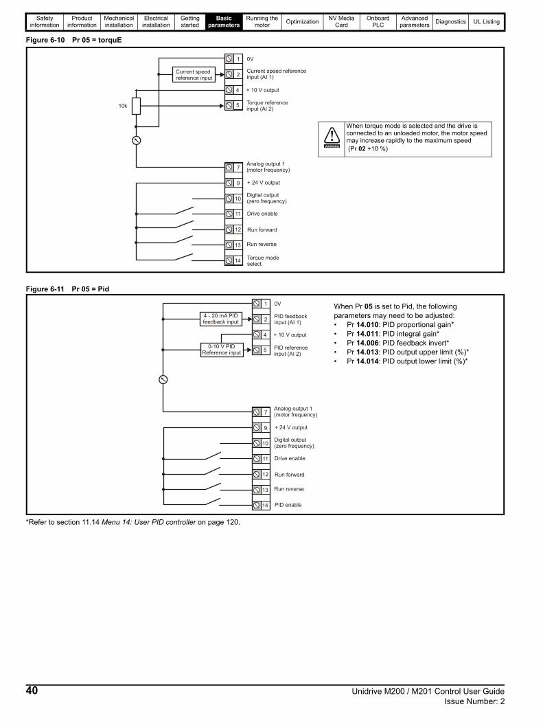
Safety information
Product information
Mechanical installation
Electrical installation
Getting started
Basic parameters
Running the motor
OptimizationNV Media
CardOnboard
PLCAdvanced
parametersDiagnostics UL Listing
Figure 6-10 Pr 05 = torquE
Figure 6-11 Pr 05 = Pid
*Refer to section 11.14 Menu 14: User PID controller on page 120.
1
2
4
0V
Current speedreference input
Current speed referenceinput (AI 1)
Torque referenceinput (AI 2)
5
+ 10 V output
7
9
10Digital output(zero frequency)
Drive enable11
12
13
14
Run reverse
Run forward
Analog output 1(motor frequency)
Torque modeselect
+ 24 V output
10k
When torque mode is selected and the drive is connected to an unloaded motor, the motor speed may increase rapidly to the maximum speed (Pr 02 +10 %)WARNING
1
2
4
0V
4 - 20 mA PIDfeedback input
PID feedbackinput (AI 1)
PID referenceinput (AI 2)
5
+ 10 V output
7
9
10Digital output(zero frequency)
Drive enable11
12
13
14
Run reverse
Run forward
Analog output 1(motor frequency)
PID enable
+ 24 V output
0-10 V PIDReference input
When Pr 05 is set to Pid, the following parameters may need to be adjusted:• Pr 14.010: PID proportional gain*• Pr 14.011: PID integral gain*• Pr 14.006: PID feedback invert*• Pr 14.013: PID output upper limit (%)*• Pr 14.014: PID output lower limit (%)*
40 Unidrive M200 / M201 Control User Guide Issue Number: 2

Safety information
Product information
Mechanical installation
Electrical installation
Getting started
Basic parameters
Running the motor
OptimizationNV Media
CardOnboard
PLCAdvanced
parametersDiagnostics UL Listing
7 Running the motorThis chapter takes the new user through all the essential steps to running a motor for the first time, in each of the possible operating modes.
For information on tuning the drive for the best performance, see Chapter 8 Optimization on page 48.
7.1 Quick start connections7.1.1 Basic requirements This section shows the basic connections which must be made for the drive to run in the required mode. For minimal parameter settings to run in each mode please see the relevant part of section 7.3 Quick start commissioning / start-up on page 46.
Table 7-1 Minimum control connection requirements for each control mode
7.2 Changing the operating modeProcedureUse the following procedure only if a different operating mode is required:
1. Ensure that the drive is not enabled, i.e. drive is in inhibit or under voltage state.
2. Change the setting of Pr 79 as follows:
The figures in the second column apply when serial communications are used.
3. Either:
• Press the red reset button
• Carry out a drive reset through serial communications by setting Pr 10.038 to 100.
When the operating mode is changed, a parameter save is carried out.
Ensure that no damage or safety hazard could arise from the motor starting unexpectedly.
The values of the motor parameters affect the protection of the motor.The default values in the drive should not be relied upon.It is essential that the correct value is entered in Pr 06 Motor Rated Current. This affects the thermal protection of the motor.
If the drive is started using the keypad it will run to the speed defined by the keypad reference (Pr 01.017). This may not be acceptable depending on the application. The user must check in Pr 01.017 and ensure that the keypad reference has been set to 0.
If the intended maximum speed affects the safety of the machinery, additional independent over-speed protection must be used.
Drive control method Requirements
Terminal modeDrive enable Speed / Torque referenceRun forward / Run reverse
Keypad mode Drive enable
Serial communicationsDrive enableSerial communications link
WARNING
CAUTION
CAUTION
WARNING
Pr 79 setting Operating mode
1 Open-loop
2 RFC-A
NOTE
Unidrive M200 / M201 Control User Guide 41Issue Number: 2

Safety information
Product information
Mechanical installation
Electrical installation
Getting started
Basic parameters
Running the motor
Optimization NV Media CardAdvanced
parametersDiagnostics UL Listing
Figure 7-1 Minimum connections to get the motor running in any operating mode (size 1 to 4)
L1 L2 L3
Fuses
L1 L2 L3 U V W
U V W
10
11
12
13
14
9
7
5
+ BR
+10 V
24 V
Run FWD
Drive enable
Run REV
Brakingresistor(optional)
Induction motor
4
2
1 FrequencyReferenceinput
0 V
1
1
Terminal
Mode
Keypad
Mode
Thermal overload for braking resistorto protect against fire risk. This must bewired to interrupt the AC supply in theevent of a fault.
42 Unidrive M200 / M201 Control User Guide Issue Number: 2

Safety information
Product information
Mechanical installation
Electrical installation
Getting started
Basic parameters
Running the motor
OptimizationNV Media
CardOnboard
PLCAdvanced
parametersDiagnostics UL Listing
Figure 7-2 Minimum connections to get the motor running in any operating mode (size 5)
Thermal overload for braking resistor to protectagainst fire risk. This must be wired to interrupt theAC supply in the event of a fault.
10
11
12
13
14
9
7
5 +10 V
24 V
Run FWD
Run REV
4
2
1 FrequencyReferenceinput
0 V
Terminal
Mode
Keypad
Mode
1
!
+ _ BR
Braking resistor(optional)
L1 L2 L3
Fuses
L1 L2 L3
U V W
U V W
Open loop
RFC-ASensorless
1
Drive enable
5
Unidrive M200 / M201 Control User Guide 43Issue Number: 2

Safety information
Product information
Mechanical installation
Electrical installation
Getting started
Basic parameters
Running the motor
Optimization NV Media CardAdvanced
parametersDiagnostics UL Listing
Figure 7-3 Minimum connections to get the motor running in any operating mode (size 6)
Thermal overload for braking resistor to protectagainst fire risk. This must be wired to interrupt theAC supply in the event of a fault.
10
11
12
13
14
9
7
5 +10 V
24 V
Run FWD
Run REV
4
2
1 FrequencyReferenceinput
0 V
Terminal
Mode
Keypad
Mode
1
!
+_BR
Braking resistor(optional)
1
L1 L2 L3
L1 L2 L3 U V W
U V W
Open loop
RFC-ASensorless
Fuses
Drive enable
6
44 Unidrive M200 / M201 Control User Guide Issue Number: 2

Safety information
Product information
Mechanical installation
Electrical installation
Getting started
Basic parameters
Running the motor
OptimizationNV Media
CardOnboard
PLCAdvanced
parametersDiagnostics UL Listing
Figure 7-4 Minimum connections to get the motor running in any operating mode (size 7 onwards)
1 Thermal overload for braking resistorto protect against fire risk. This must bewired to interrupt the AC supply in theevent of a fault.
Terminal
Mode
10
11
13
9
14
7
12
4
5
24 V
Run FWD
Run REV
Frequencyreferenceinput
0V
+10V
2
1
L1 L2 L3
Fuses
L1 L2 L3
Open Loop
RFC-ASensorless
U V W
U V W
1
!
Braking resistor(optional)
+DC BRAKE
7 8 9Drive Enable
Unidrive M200 / M201 Control User Guide 45Issue Number: 2

Safety information
Product information
Mechanical installation
Electrical installation
Getting started
Basic parameters
Running the motor
Optimization NV Media CardAdvanced
parametersDiagnostics UL Listing
7.3 Quick start commissioning / start-up7.3.1 Open loop
Action Detail
Before power-up
Ensure:• The drive enable signal is not given, terminal 11 is open.• Run signal is not given, terminal 12/13 is open.• Motor is connected to the drive.
• The motor connection is correct for the drive or • The correct supply voltage is connected to the drive.
Power-up the drive
Verify that open loop mode is displayed as the drive powers up.If the mode is incorrect see section 5.6 Changing the operating mode on page 26.Ensure:• Drive displays ‘inh’ (enable terminal is open).If the drive trips, see section 12 Diagnostics on page 129.
Enter motor nameplate details
Set maximum speed
Enter:• Maximum speed in Pr 02 (Hz)
Set acceleration / deceleration rates
Enter:• Acceleration rate in Pr 03 (s/100 Hz)• Deceleration rate in Pr 04 (s/100 Hz) (If braking resistor is installed, set Pr 28 = FAST. Also ensure
Pr 10.030 and Pr 10.031 and Pr 10.061 are set correctly, otherwise premature ‘It.br’ trips may be seen).
Autotune
The drive is able to perform either a stationary or a rotating autotune. The motor must be at a standstill before an autotune is enabled. A rotating autotune should be used whenever possible so the measured value of power factor of the motor is used by the drive.
• A stationary autotune can be used when the motor is loaded and it is not possible to uncouple the load from the motor shaft. A stationary autotune measures the stator resistance of the motor and the dead time compensation for the drive. These are required for good performance in vector control modes. A stationary autotune does not measure the power factor of the motor so the value on the motor nameplate must be entered into Pr 09.
• A rotating autotune should only be used if the motor is uncoupled. A rotating autotune first performs
a stationary autotune before rotating the motor at 2/3 base speed in the direction selected. The rotating autotune measures the power factor of the motor.
To perform an autotune:• Set Pr 38 = 1 for a stationary autotune or set Pr 38 = 2 for a rotating autotune• Close the Drive Enable signal (apply +24 V to terminal 11). The drive will display ’rdy’.• Give a run command (apply +24 V to terminal 12 - Run forward or terminal 13 - Run reverse on
Unidrive M200; press keypad start button on M201). The display will flash ’tuning’ while the drive is performing the autotune.
• Wait for the drive to display ‘inh’ and for the motor to come to a standstill.If the drive trips, see Chapter 12 Diagnostics on page 129.• Remove the drive enable and run signal from the drive.
Save parameters Select 'Save' in Pr 00 or Pr mm.000 (alternatively enter a value of 1001) and press the red reset button.
Run Drive is now ready to run
Motor rated current in Pr 06 (Amps)
Motor rated speed in Pr 07 (rpm / min-1)
Motor rated voltage in Pr 08 (Volts)
Motor rated power factor (cos ) in Pr 09
MOT. 3 LS 80 L TN 734570 BJ 002 Kg 940 C S1IP 55 I cl.F
V Hz min kW cos -1 A
230 50 2800 0,75 0,83 0,3
123 4
Pr 02
t
100Hz
Pr 03t
Pr 04
A rotating autotune will cause the motor to accelerate up to 2/3 base speed in the direction selected regardless of the reference provided. Once complete the motor will coast to a stop. The enable signal must be removed before the drive can be made to run at the required reference.The drive can be stopped at any time by removing the run signal or removing the drive enable.
WARNING
cos
LS
RS
46 Unidrive M200 / M201 Control User Guide Issue Number: 2

Safety information
Product information
Mechanical installation
Electrical installation
Getting started
Basic parameters
Running the motor
OptimizationNV Media
CardOnboard
PLCAdvanced
parametersDiagnostics UL Listing
7.3.2 RFC - A mode
* Slip is required for RFC-A mode.
Action Detail
Before power-up
Ensure:• The drive enable signal is not given, terminal 11 is open.• Run signal is not given, terminal 12/13 is open.• Motor is connected to the drive.
• The motor connection is correct for the drive or • The correct supply voltage is connected to the drive.
Power-up the drive
Verify that RFC-A mode is displayed as the drive powers up.If the mode is incorrect see section 5.6 Changing the operating mode on page 26.Ensure:• Drive displays ‘inh’ (enable terminal is open).If the drive trips, see Chapter 12 Diagnostics on page 129.
Enter motor nameplate details
Set maximum speed
Enter:• Maximum speed in Pr 02 (Hz)
Set acceleration / deceleration rates
Enter:• Acceleration rate in Pr 03 (s/100 Hz)• Deceleration rate in Pr 04 (s/100 Hz) (If the braking resistor is installed, set Pr 28 = FAST. Also ensure Pr 10.030, Pr 10.031 and Pr 10.061 are set correctly, otherwise premature ‘It.br’ trips may be seen).
Autotune
The drive is able to perform either a stationary or a rotating autotune. The motor must be at a standstill before an autotune is enabled. A stationary autotune will give moderate performance whereas a rotating autotune will give improved performance as it measures the actual values of the motor parameters required by the drive.
• A stationary autotune can be used when the motor is loaded and it is not possible to uncouple the load from the motor shaft. The stationary autotune measures the stator resistance and transient inductance of the motor. These are used to calculate the current loop gains, and at the end of the test the values in Pr 04.013 and Pr 04.014 are updated. A stationary autotune does not measure the power factor of the motor so the value on the motor nameplate must be entered into Pr 09.
• A rotating autotune should only be used if the motor is uncoupled. A rotating autotune first performs a
stationary autotune before rotating the motor at 2/3 base speed in the direction selected. The rotating autotune measures the stator inductance of the motor and calculates the power factor.
To perform an autotune:• Set Pr 38 = 1 for a stationary autotune or set Pr 38 = 2 for a rotating autotune• Close the drive enable signal (apply +24 V to terminal 11). The drive will display ’rdy’.• Give a run command (apply +24 V to terminal 12 - Run forward or terminal 13 - Run reverse on Unidrive
M200; press keypad start button on M201). The display will flash ‘tuning’ while the drive is performing the autotune.
• Wait for the drive to display ’inh’ and for the motor to come to a standstillIf the drive trips, see Chapter 12 Diagnostics on page 129.• Remove the drive enable and run signal from the drive.
Save parameters Select 'Save' in Pr 00 or Pr mm.000 (alternatively enter a value of 1001) and press red reset button.
Run The drive is now ready to run
Motor rated current in Pr 06 (Amps)
Motor rated speed in Pr 07 (rpm / min-1)
Motor rated voltage in Pr 08 (Volts)
Motor rated power factor (cos ) in Pr 09
MOT. 3 LS 80 L TN 734570 BJ 002 Kg 940 C S1IP 55 I cl.F
V Hz min kW cos -1 A
230 50 2800 0,75 0,83 0,3
123 4
Pr 02
t
100Hz
Pr 03t
Pr 04
A rotating autotune will cause the motor to accelerate up to 2/3 base speed in the direction selected regardless of the reference provided. Once complete the motor will coast to a stop. The enable signal must be removed before the drive can be made to run at the required reference.
The drive can be stopped at any time by removing the run signal or removing the drive enable.WARNING
cos
LS
TNm
N rpm
saturationbreak-points
RS
LS
Unidrive M200 / M201 Control User Guide 47Issue Number: 2

Safety information
Product information
Mechanical installation
Electrical installation
Getting started
Basic parameters
Running the motor Optimization NV Media
CardOnboard
PLCAdvanced
parametersDiagnostics UL Listing
8 OptimizationThis chapter takes the user through methods of optimizing the drive set-up and maximize the performance. The auto-tuning features of the drive simplify the optimization tasks.
8.1 Motor map parameters8.1.1 Open loop motor control
Pr 06 05.007 Motor Rated Current Defines the maximum continuous motor current
• The rated current parameter must be set to the maximum continuous current of the motor. The motor rated current is used in the following:• Current limits (see section section 8.3 Current limits on page 54, for more information)• Motor thermal overload protection (see section section 8.4 Motor thermal protection on page 54, for more information)• Vector mode voltage control (see Control Mode later in this table)• Slip compensation (see Enable Slip Compensation (05.027), later in this table)• Dynamic V/F control
Pr 08 05.009 Motor Rated Voltage Defines the voltage applied to the motor at rated frequency
Pr 39 05.006 Motor Rated Frequency Defines the frequency at which rated voltage is applied
The Motor Rated Voltage (Pr 08) and the Motor Rated Frequency (Pr 39) are used to define the voltage to frequency characteristic applied to the motor (see Control Mode, later in this table). The Motor Rated Frequency is also used in conjunction with the motor rated speed to calculate the rated slip for slip compensation (see Motor Rated Speed, later in this table).
Pr 07 05.008 Motor Rated Speed Defines the full load rated speed of the motor
Pr 40 05.011 Number of Motor Poles Defines the number of motor poles
The motor rated speed and the number of poles are used with the motor rated frequency to calculate the rated slip of induction machines in Hz.
Rated slip (Hz) = Motor rated frequency - (Number of pole pairs x [Motor rated speed / 60]) =
If Pr 07 is set to 0 or to synchronous speed, slip compensation is disabled. If slip compensation is required this parameter should be set to the nameplate value, which should give the correct rpm for a hot machine. Sometimes it will be necessary to adjust this when the drive is commissioned because the nameplate value may be inaccurate. Slip compensation will operate correctly both below base speed and within the field-weakening region. Slip compensation is normally used to correct for the motor speed to prevent speed variation with load. The rated load rpm can be set higher than synchronous speed to deliberately introduce speed droop. This can be useful to aid load sharing with mechanically coupled motors.
Pr 40 is also used in the calculation of the motor speed display by the drive for a given output frequency. When Pr 40 is set to ‘Auto’, the number of motor poles is automatically calculated from the rated frequency Pr 39, and the motor rated speed Pr 07.
Number of poles = 120 x (Rated Frequency (Pr 39) / Rated Speed (Pr 07)) rounded to the nearest even number.
Pr 43 05.010 Motor Rated Power Factor Defines the angle between the motor voltage and current
The power factor is the true power factor of the motor, i.e. the angle between the motor voltage and current. The power factor is used in conjunction with the Motor Rated Current (Pr 06), to calculate the rated active current and magnetising current of the motor. The rated active current is used extensively to control the drive, and the magnetising current is used in vector mode stator resistance compensation. It is important that this parameter is set up correctly. The drive can measure the motor rated power factor by performing a rotating autotune (see Autotune (Pr 38), below).
Outputvoltage
Pr / 208
Pr 08
Pr / 239 Pr 39 Outputfrequency
Output voltage characteristic
Pr39Pr40
2------------- Pr07
60-------------
=
48 Unidrive M200 / M201 Control User Guide Issue Number: 2

Safety information
Product information
Mechanical installation
Electrical installation
Getting started
Basic parameters
Running the motor Optimization NV Media
CardOnboard
PLCAdvanced
parametersDiagnostics UL Listing
Pr 38 05.012 Autotune
There are two autotune tests available in open loop mode, a stationary and a rotating test. A rotating autotune should be used whenever possible so the measured value of power factor of the motor is used by the drive.
• A stationary autotune can be used when the motor is loaded and it is not possible to remove the load from the motor shaft. The stationary test measures the Stator Resistance (05.017), Transient Inductance (05.024), Maximum Deadtime Compensation (05.059) and Current At Maximum Deadtime Compensation (05.060) which are required for good performance in vector control modes (see Control Mode later in this table). The stationary autotune does not measure the power factor of the motor so the value on the motor nameplate must be entered into Pr 09. To perform a Stationary autotune, set Pr 38 to 1, and provide the drive with both an enable signal (on terminal 11) and a run signal (on terminals 12 or 13).
• A rotating autotune should only be used if the motor is unloaded. A rotating autotune first performs a stationary autotune, as above, then a rotating test is performed in which the motor is accelerated with currently selected ramps up to a frequency of Motor Rated Frequency (Pr 39) x 2/3, and the frequency is maintained at that level for 4 seconds. Stator Inductance (05.025) is measured and this value is used in conjunction with other motor parameters to calculate Motor Rated Power Factor (Pr 09). To perform a Rotating autotune, set Pr 38 to 2, and provide the drive with both an enable signal (on terminal 11) and a run signal (on terminals 12 or 13).
Following the completion of an autotune test the drive will go into the inhibit state. The drive must be placed into a controlled disable condition before the drive can be made to run at the required reference. The drive can be put in to a controlled disable condition by removing the signal from terminal 11, setting the Drive Enable (06.015) to OFF (0) or disabling the drive via the Control Word (06.042) and Control Word Enable (06.043).
Pr 41 05.014 Control Mode
There are several voltage modes available which fall into two categories, vector control and fixed boost.
Vector control
Vector control mode provides the motor with a linear voltage characteristic from 0 Hz to Motor Rated Frequency, and then a constant voltage above motor rated frequency. When the drive operates between motor rated frequency/50 and motor rated frequency/4, full vector based stator resistance compensation is applied. When the drive operates between motor rated frequency/4 and motor rated frequency/2 the stator resistance compensation is gradually reduced to zero as the frequency increases. For the vector modes to operate correctly the Motor Rated Power Factor (Pr 09), Stator Resistance (05.017), Maximum Deadtime Compensation (05.059) and current at Maximum Deadtime Compensation (05.060) are all required to be set up accurately. The drive can be made to measure these by performing an autotune (see Pr 38 Autotune). The drive can also be made to measure the stator resistance automatically every time the drive is enabled or the first time the drive is enabled after it is powered up, by selecting one of the vector control voltage modes.
(0) Ur S = The stator resistance is measured and the parameters for the selected motor map are over-written each time the drive is made to run. This test can only be done with a stationary motor where the flux has decayed to zero. Therefore this mode should only be used if the motor is guaranteed to be stationary each time the drive is made to run. To prevent the test from being done before the flux has decayed there is a period of 1 second after the drive has been in the ready state during which the test is not done if the drive is made to run again. In this case, previously measured values are used. Ur S mode ensures that the drive compensates for any change in motor parameters due to changes in temperature. The new value of stator resistance is not automatically saved to the drive's EEPROM.
(4) Ur I = The stator resistance is measured when the drive is first made to run after each power-up. This test can only be done with a stationary motor. Therefore this mode should only be used if the motor is guaranteed to be stationary the first time the drive is made to run after each power-up. The new value of stator resistance is not automatically saved to the drive's EEPROM.
(1) Ur = The stator resistance and voltage offset are not measured. The user can enter the motor and cabling resistance into the Stator Resistance (05.017). However this will not include resistance effects within the drive inverter. Therefore if this mode is to be used, it is best to use an autotune test initially to measure the stator resistance.
(3) Ur_Auto= The stator resistance is measured once, the first time the drive is made to run. After the test has been completed successfully the Control Mode (Pr 41) is changed to Ur mode. The Stator Resistance (05.017) parameter is written to, and along with the Control Mode (Pr 41), are saved in the drive's EEPROM. If the test fails, the voltage mode will stay set to Ur Auto and the test will be repeated next time the drive is made to run.
Fixed boostThe stator resistance is not used in the control of the motor, instead a fixed characteristic with low frequency voltage boost as defined by Pr 42, is used. Fixed boost mode should be used when the drive is controlling multiple motors. There are three settings of fixed boost available:
(2) Fixed = This mode provides the motor with a linear voltage characteristic from 0 Hz to Motor Rated Frequency (Pr 39), and then a constant voltage above rated frequency.(5) Square = This mode provides the motor with a square law voltage characteristic from 0 Hz to Motor Rated Frequency (Pr 39), and then a constant voltage above rated frequency. This mode is suitable for variable torque applications like fans and pumps where the load is proportional to the square of the speed of the motor shaft. This mode should not be used if a high starting torque is required.(6) Fixed Tapered = This mode provides the motor with a linear voltage characteristic with a tapered slip limit.
Unidrive M200 / M201 Control User Guide 49Issue Number: 2

Safety information
Product information
Mechanical installation
Electrical installation
Getting started
Basic parameters
Running the motor Optimization NV Media
CardOnboard
PLCAdvanced
parametersDiagnostics UL Listing
Pr 41 05.014 Control Mode (cont)
For mode 2 and 5, at low frequencies (from 0 Hz to ½ x Pr 39) a voltage boost is applied as defined by Pr 42 as shown below:
Pr 05.027 Enable Slip Compensation
When a motor, being controlled in open loop mode, has load applied a characteristic of the motor is that the output speed droops in proportion to the load applied as shown:
In order to prevent the speed droop shown above slip compensation should be enabled. To enable slip compensation Pr 05.027 must be set to a 100 % (this is the default setting), and the motor rated speed must be entered in Pr 07 (Pr 05.008).
The motor rated speed parameter should be set to the synchronous speed of the motor minus the slip speed. This is normally displayed on the motor nameplate, i.e. for a typical 18.5 kW, 50 Hz, 4 pole motor, the motor rated speed would be approximately 1465 rpm. The synchronous speed for a 50 Hz, 4 pole motor is 1500 rpm, so therefore the slip speed would be 35 rpm. If the synchronous speed is entered in Pr 07, slip compensation will be disabled. If too small a value is entered in Pr 07, the motor will run faster than the demanded frequency. The synchronous speeds for 50 Hz motors with different numbers of poles are as follows:
2 pole = 3000 rpm, 4 pole = 1500 rpm, 6pole =1000 rpm, 8 pole = 750 rpm
Outputvoltage
Pr / 208
Pr 08
Pr / 239 Pr 39 Outputfrequency
Output voltage characteristic(Fd)
Voltage boostPr 42
Pr 08
Pr42
Pr 39
Pr + [(freq/Pr ) x (Pr - Pr )]42 39 08 392
OutputVoltage
VoltageBoost
OutputFrequency
Shaft speed
Demanded speed
Load
50 Unidrive M200 / M201 Control User Guide Issue Number: 2

Safety information
Product information
Mechanical installation
Electrical installation
Getting started
Basic parameters
Running the motor Optimization NV Media
CardOnboard
PLCAdvanced
parametersDiagnostics UL Listing
8.1.2 RFC-A mode
Pr 06 05.007 Motor Rated Current Defines the maximum motor continuous current
The motor rated current parameter must be set to the maximum continuous current of the motor. The motor rated current is used in the following:
• Current limits (see section 8.3 Current limits on page 54, for more information).• Motor thermal overload protection (see section 8.4 Motor thermal protection on page 54, for more information)• Vector control algorithm
Pr 08 05.009 Motor Rated Voltage Defines the voltage applied to the motor at rated frequency
Pr 39 05.006 Motor Rated Frequency Defines the frequency at which rated voltage is applied
The Motor Rated Voltage (Pr 08) and the Motor Rated Frequency (Pr 39) are used to define the voltage to frequency characteristic applied to the motor. The motor rated frequency is also used in conjunction with the motor rated speed to calculate the rated slip for slip compensation (see Motor Rated Speed (Pr 07), later in this table).
Pr 07 05.008 Motor Rated Speed Defines the full load rated speed of the motor and slip
Pr 40 05.011 Number of Motor Poles Defines the number of motor poles
The motor rated speed and motor rated frequency are used to determine the full load slip of the motor which is used by the vector control algorithm.
Incorrect setting of this parameter has the following effects:
• Reduced efficiency of motor operation• Reduction of maximum torque available from the motor• Reduced transient performance• Inaccurate control of absolute torque in torque control modesThe nameplate value is normally the value for a hot motor; however, some adjustment may be required when the drive is commissioned if the nameplate value is inaccurate. A fixed value can be entered in this parameter.
When Pr 40 is set to 'Auto', the number of motor poles is automatically calculated from the Motor Rated Frequency (Pr 39), and the Motor Rated Speed (Pr 07).
Number of poles = 120 x (Motor Rated Frequency (Pr 39 / Motor Rated Speed (Pr 07) rounded to the nearest even number.
Pr 09 05.010 Motor Rated Power Factor Defines the angle between the motor voltage and current
The power factor is the true power factor of the motor, i.e. the angle between the motor voltage and current. If the Stator Inductance (05.025) is set to zero then the power factor is used in conjunction with the Motor Rated Current (Pr 06) and other motor parameters to calculate the rated active and magnetising currents of the motor, which are used in the vector control algorithm. If the stator inductance has a non-zero value this parameter is not used by the drive, but is continuously written with a calculated value of power factor. The stator inductance can be measured by the drive by performing a rotating autotune (see Autotune (Pr 38), later in this table).
Outputvoltage
Pr / 208
Pr 08
Pr / 239 Pr 39 Outputfrequency
Output voltage characteristic
Unidrive M200 / M201 Control User Guide 51Issue Number: 2

Safety information
Product information
Mechanical installation
Electrical installation
Getting started
Basic parameters
Running the motor Optimization NV Media
CardOnboard
PLCAdvanced
parametersDiagnostics UL Listing
Pr 38 05.012 Autotune
There are three autotune tests available in RFC-A mode, a stationary test, a rotating test and a mechanical load measurement test. A stationary autotune will give moderate performance whereas a rotating autotune will give improved performance as it measures the actual values of the motor parameters required by the drive. An inertia measurement test should be performed separately to a stationary or rotating autotune.
It is highly recommended that a rotating autotune is performed (Pr 38 set to 2).
• A stationary autotune can be used when the motor is loaded and it is not possible to remove the load from the motor shaft. The stationary autotune measures the Stator Resistance (05.017) and Transient Inductance (05.024) of the motor. These are used to calculate the current loop gains, and at the end of the test the values in Pr 04.013 and Pr 04.014 are updated. A stationary autotune does not measure the power factor of the motor so the value on the motor nameplate must be entered into Pr 09. To perform a Stationary autotune, set Pr 38 to 1, and provide the drive with both an enable signal (on terminal 11) and a run signal (on terminal 12 or 13).
• A rotating autotune should only be used if the motor is unloaded. A rotating autotune first performs a stationary autotune, a rotating test is then performed which the motor is accelerated with currently selected ramps up to a frequency of Motor Rated Frequency (Pr 39) x 2/3, and the frequency is maintained at the level for up to 40 s. During the rotating autotune the Stator Inductance (05.025), and the motor saturation breakpoints (Pr 05.029, Pr 05.030, Pr 05.062 and Pr 05.063) are modified by the drive. The power factor is also modified for user information only, but is not used after this point as the stator inductance is used in the vector control algorithm instead. To perform a Rotating autotune, set Pr 38 to 2, and provide the drive with both an enable signal (on terminal 11) and a run signal (on terminal 12 or 13).
• The mechanical load test can measure the total inertia of the load and the motor. A series of progressively larger torque levels are applied to the motor (20 %, 40 % … 100 % of rated torque) to accelerate the motor up to ¾ x Motor Rated Speed (Pr 07) to determine the inertia from the acceleration/deceleration time. The test attempts to reach the required speed within 5s, but if this fails, the next torque level is used. When 100 % torque is used, the test allows 60 s for the required speed to be reached, but if this is unsuccessful, a tun.1 trip is initiated. To reduce the time taken for the test, it is possible to define the level of torque to be used for the test by setting Mechanical Load Test Level (05.021) to a non-zero value. When the test level is defined, the test is only carried out at the defined test level and 60 s is allowed for the motor to reach the required speed. It should be noted that if the maximum speed allows for flux weakening then it may not be possible to achieve the required torque level to accelerate the motor fast enough. If this is the case, the maximum speed reference should be reduced.
1. The motor must be stationary at the start of the test. 2. The motor is accelerated in the required direction up to ¾ of the maximum speed reference and then decelerated to zero speed. 3. The test is repeated with progressively higher torque until the required speed is reached.
To perform a mechanical load measurement autotune, set Pr 38 to 3, and provide the drive with both an enable signal (on terminal 11) and a run signal (on terminal 12 or 13). Following the completion of an autotune test the drive will go into the inhibit state. The drive must be placed into a controlled disable condition before the drive can be made to run at the required reference. The drive can be put in to a controlled disable condition by removing the drive enable signal from terminal 11, setting the Drive Enable (06.015) to OFF (0) or disabling the drive via the control word (Pr 06.042 & Pr 06.043).
04.013 / 04.014 Current Loop Gains
The current loop gains proportional (Kp) and integral (Ki) gains control the response of the current loop to a change in current (torque) demand. The default values give satisfactory operation with most motors. However, for optimal performance in dynamic applications it may be necessary to change the gains to improve the performance. The Current Controller Kp Gain (04.013) is the most critical value in controlling the performance. The values for the current loop gains can be calculated by performing a stationary or rotating autotune (see Autotune Pr 38 earlier in this table) the drive measures the Stator Resistance (05.017) and Transient Inductance (05.024) of the motor and calculates the current loop gains.
This will give a step response with minimum overshoot after a step change of current reference. The proportional gain can be increased by a factor of 1.5 giving a similar increase in bandwidth; however, this gives a step response with approximately 12.5 % overshoot. The equation for the integral gain gives a conservative value. In some applications where it is necessary for the reference frame used by the drive to dynamically follow the flux very closely (i.e. high speed Sensorless RFC-A induction motor applications) the integral gain may need to have a significantly higher value.
NOTE
52 Unidrive M200 / M201 Control User Guide Issue Number: 2

Safety information
Product information
Mechanical installation
Electrical installation
Getting started
Basic parameters
Running the motor Optimization NV Media
CardOnboard
PLCAdvanced
parametersDiagnostics UL Listing
Frequency Loop Gains(Pr 65 03.010, Pr 66 03.011
The frequency loop gains control the response of the frequency controller to a change in frequency demand. The frequency controller includes proportional (Kp) and integral (Ki) feed forward terms, and a differential (Kd) feedback term. The drive holds two sets of these gains and either set may be selected for use by the frequency controller with Pr 03.016. If Pr 03.016 = 0, gains Kp1, Ki1 and Kd1 (Pr 03.010 to Pr 03.012) are used, and if Pr 03.016 = 1, gains Kp2, Ki2 and Kd2 (Pr 03.013 to Pr 03.015) are used. Pr 03.016 may be changed when the drive is enabled or disabled.
Frequency Controller Proportional Gain (Kp), Pr 65 03.010 and Pr 03.013
If the proportional gain has a value and the integral gain is set to zero the controller will only have a proportional term, and there must be a frequency error to produce a torque reference. Therefore as the motor load increases there will be a difference between the reference and actual frequencies. This effect, called regulation, depends on the level of the proportional gain, the higher the gain the smaller the frequency error for a given load. If the proportional gain is too high either the acoustic noise produced by numerical quantization becomes unacceptable, or the stability limit is reached.
Frequency Controller Integral Gain (Ki), Pr 66 03.011 and Pr 03.014
The integral gain is provided to prevent frequency regulation. The error is accumulated over a period of time and used to produce the necessary torque demand without any frequency error. Increasing the integral gain reduces the time taken for the frequency to reach the correct level and increases the stiffness of the system, i.e. it reduces the positional displacement produced by applying a load torque to the motor. Unfortunately increasing the integral gain also reduces the system damping giving overshoot after a transient. For a given integral gain the damping can be improved by increasing the proportional gain. A compromise must be reached where the system response, stiffness and damping are all adequate for the application. For RFC-A Sensorless mode, it is unlikely that the integral gain can be increased much above 0.50.
Differential Gain (Kd), Pr 03.012 and Pr 03.015
The differential gain is provided in the feedback of the frequency controller to give additional damping. The differential term is implemented in a way that does not introduce excessive noise normally associated with this type of function. Increasing the differential term reduces the overshoot produced by under-damping, however, for most applications the proportional and integral gains alone are sufficient.
Gain Change Threshold, Pr 03.017
If the Frequency Controller Gain Select (03.016) = 2, gains Kp1, Ki1 and Kd1 (Pr 03.010 to Pr 03.012) are used while the modulus of the frequency demand is less than the value held by Gain Change Threshold (03.017), else gains Kp2, Ki2 and Kd2 (Pr 03.013 to Pr 03.015) will be used.
Tuning the frequency loop gains:
This involves the connecting of an oscilloscope to analog output 1 tomonitor the frequency feedback.Give the drive a step change in frequency reference and monitor theresponse of the drive on the oscilloscope.The proportional gain (Kp) should be set up initially. The valueshould be increased up to the point where the frequency overshootsand then reduced slightly.The integral gain (Ki) should then be increased up to the point wherethe frequency becomes unstable and then reduced slightly.It may now be possible to increase the proportional gain to a highervalue and the process should be repeated until the system responseapproaches the ideal response as shown.The diagram shows the effect of incorrect P and I gain settings aswell as the ideal response.
Frequency demand
Insufficient proportionalgain [Pr ]65
Excessive proportionalgain [Pr 65]
Excessive integral gain[Pr ]66
Ideal response
Unidrive M200 / M201 Control User Guide 53Issue Number: 2

Safety information
Product information
Mechanical installation
Electrical installation
Getting started
Basic parameters
Running the motor Optimization NV Media
CardOnboard
PLCAdvanced
parametersDiagnostics UL Listing
8.2 Maximum motor rated currentSize 1 to 4:
The maximum motor rated current is the Maximum Heavy Duty Current Rating (Pr 77).
The values for the Heavy Duty rating can be found in the Power Installation Guide.
Size 5 onwards:
The maximum motor rated current allowed by the drive is greater than the Maximum Heavy Duty Current Rating (Pr 77). The ratio between the Normal Duty rating and the Maximum Heavy Duty Current Rating (Pr 77) varies between drive sizes. The values for the Normal and Heavy Duty rating can be found in the Power Installation Guide. If the Motor Rated Current (Pr 06) is set above the Maximum Heavy Duty Current Rating (Pr 77), the current limits and the motor thermal protection scheme are modified (see section 8.3 Current limits on page 54 and section 8.4 Motor thermal protection below for further information).
8.3 Current limitsThe default setting for the current limit parameters is:
• 165 % x motor rated torque producing current for open loop mode.• 175 % x motor rated torque producing current for RFC-A mode.
There are three parameters which control the current limits:
• Motoring current limit: power flowing from the drive to the motor• Regen current limit: power flowing from the motor to the drive• Symmetrical current limit: current limit for both motoring and regen
operation
The lowest of either the motoring and regen current limit, or the symmetrical current limit applies.
The maximum setting of these parameters depends on the values of motor rated current, drive rated current and the power factor.
With size 5 upwards, increasing the motor rated current (Pr 06 / Pr 05.007) above the Heavy Duty rating (default value), will automatically reduce the current limits in Pr 04.005 to Pr 04.007. If the motor rated current is then set to or below the Heavy Duty rating, the current limits will be left at their reduced values.
The drive can be oversized to permit a higher current limit setting to provide higher accelerating torque as required up to a maximum of 1000 %.
8.4 Motor thermal protectionA time constant thermal model is provided to estimate the motor temperature as a percentage of its maximum allowed temperature.
The motor thermal protection is modelled using losses in the motor. The losses in the motor are calculated as a percentage value, so that under these conditions the Motor Protection Accumulator (04.019) would eventually reach 100 %.
Percentage losses = 100 % x [Load related losses]
Where:
Load related losses = [I / (K1 x IRated)]2
Where:
I = Current Magnitude (Pr 88)
IRated = Motor Rated Current (Pr 06)
If Motor Rated Current (Pr 06) Maximum Heavy Duty Current (Pr 77)
Figure 8-1 Motor thermal protection (Heavy Duty)
If Pr 04.025 is 0 the characteristic is for a motor which can operate at rated current over the whole speed range. Induction motors with this type of characteristic normally have forced cooling. If Pr 04.025 is 1 the characteristic is intended for motors where the cooling effect of motor fan reduces with reduced motor speed below 50 % of base speed/ frequency. The maximum value for K1 is 1.05, so that above the knee of the characteristics the motor can operate continuously up to 105 % current.
Figure 8-2 Motor thermal protection (Normal Duty)
Both settings of Pr 04.025 are intended for motors where the cooling effect of the motor fan reduces with reduced motor speed, but with different speeds below which the cooling effect is reduced. If Pr 04.025 is 0 the characteristic is intended for motors where the cooling effect reduces with motor speed below 15 % of base speed/frequency. If Pr 04.025 is 1 the characteristic is intended for motors where the cooling effect reduces with motor speed below 50 % of base speed/frequency. The maximum value for K1 is 1.01, so that above the knee of the characteristics the motor can operate continuously up to 101 % current
When the estimated temperature in Pr 04.019 reaches 100 % the drive takes some action depending on the setting of Pr 04.016. If Pr 04.016 is 0, the drive trips when Pr 04.019 reaches 100 %. If Pr 04.016 is 1, the current limit is reduced to (K - 0.05) x 100 % when Pr 04.019 reaches 100 %.
The current limit is set back to the user defined level when Pr 04.019 falls below 95 %. The thermal model temperature accumulator accumulates the temperature of the motor while the drive remains powered-up. By default, the accumulator is set to the power down value at power up. If the rated current defined by Pr 06 is altered, the accumulator is reset to zero.
The default setting of the thermal time constant (Pr 04.015) is 179 s which is equivalent to an overload of 150 % for 120 s from cold.
0.00
0.70
1.00
Pr = 0Pr = 1
04.02504.025
1.001.05
Base speed/frequency
50% of basespeed/frequency
K
0.00
0.70
1.00
Pr = 0Pr = 1
04.02504.025
1.00 1.01
Base speed/frequency
50% ofbase speed/frequency
15% ofbase speed/
frequency
K
54 Unidrive M200 / M201 Control User Guide Issue Number: 2

Safety information
Product information
Mechanical installation
Electrical installation
Getting started
Basic parameters
Running the motor Optimization NV Media
CardOnboard
PLCAdvanced
parametersDiagnostics UL Listing
8.5 Switching frequencyThe default switching frequency is 3 kHz, however this can be increased up to a maximum of 16 kHz by Pr 37.
If switching frequency is increased from 3 kHz the following apply:
1. Increased heat loss in the drive, which means that derating to the output current must be applied.See the derating tables for switching frequency and ambient temperature in the Power Installation Guide.
2. Reduced heating of the motor - due to improved output waveform quality.
3. Reduced acoustic noise generated by the motor.4. Increased sample rate on the speed and current controllers. A trade
off must be made between motor heating, drive heating and the demands of the application with respect to the sample time required.
Lowest switching frequency in RFC-A mode is 2 kHz.
Table 8-1 Sample rates for various control tasks at each switching frequency
8.5.1 Field weakening (constant power) operationThe drive can be used to run an induction machine above synchronous speed into the constant power region. The speed continues to increase and the available shaft torque reduces. The characteristics below show the torque and output voltage characteristics as the speed is increased above the rated value.
Figure 8-3 Torque and rated voltage against speed
Care must be taken to ensure the torque available above base speed is sufficient for the application to run satisfactorily.
The saturation breakpoint parameters (Pr 05.029, Pr 05. 030, Pr 05.062 and Pr 05.063) found during the autotune in RFC-A mode ensure the magnetizing current is reduced in the correct proportion for the specific motor. (In open loop mode the magnetizing current is not actively controlled).
8.5.2 Maximum frequencyIn all operating modes the maximum output frequency is limited to
550 Hz.
8.5.3 Over-modulation (open-loop only)The maximum output voltage level of the drive is normally limited to an equivalent of the drive input voltage minus voltage drops within the drive (the drive will also retain a few percent of the voltage in order to maintain current control). If the motor rated voltage is set at the same level as the supply voltage, some pulse deletion will occur as the drive output voltage approaches the rated voltage level. If Pr 05.020 (Over-modulation enable) is set to 1 the modulator will allow over modulation, so that as the output frequency increases beyond the rated frequency the voltage continues to increase above the rated voltage.
This can be used for example:
• To obtain high output frequencies with a low switching frequency which would not be possible with space vector modulation limited to unity modulation depth,
or
• In order to maintain a higher output voltage with a low supply voltage.
The disadvantage is that the machine current will be distorted as the modulation depth increases above unity, and will contain a significant amount of low order odd harmonics of the fundamental output frequency. The additional low order harmonics cause increased losses and heating in the motor.
8.5.4 Switching frequency/Output frequency ratioWith a default switching frequency of 3 kHz, the maximum output frequency should be limited to 250 Hz. Ideally, a minimum ratio of 12:1 should be maintained between the switching frequency and the output frequency. This ensures the number of switchings per cycle is sufficient to ensure the output waveform quality is maintained at a minimum level.
Level0.667,1 kHz
3, 6, 12kHz
2, 4, 8, 16kHz
Open loop
RFC-A
Level 1 250 s 167 s
2 kHz = 250 s4 kHz = 125 s8 kHz = 125 s16 kHz = 125 s
Peak limitCurrent
controllers
Level 2 250 sCurrent limit and ramps
Speed controller
and ramps
Level 3 1 ms Voltage controller
Level 4 4 msTime critical user
interface
BackgroundNon-time critical user
interface
NOTE
Ratedvoltage
Torque
Speed
SpeedRated speed
Unidrive M200 / M201 Control User Guide 55Issue Number: 2
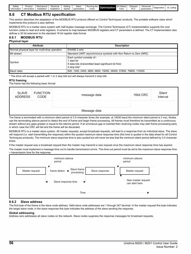
Safety information
Product information
Mechanical installation
Electrical installation
Getting started
Basic parameters
Running the motor Optimization NV Media
CardOnboard
PLCAdvanced
parametersDiagnostics UL Listing
8.6 CT Modbus RTU specificationThis section describes the adaptation of the MODBUS RTU protocol offered on Control Techniques' products. The portable software class which implements this protocol is also defined.
MODBUS RTU is a master slave system with half-duplex message exchange. The Control Techniques (CT) implementation supports the core function codes to read and write registers. A scheme to map between MODBUS registers and CT parameters is defined. The CT implementation also defines a 32 bit extension to the standard 16 bit register data format.
8.6.1 MODBUS RTUPhysical layer
* The drive will accept a packet with 1 or 2 stop bits but will always transmit 2 stop bits
RTU framingThe frame has the following basic format
The frame is terminated with a minimum silent period of 3.5 character times (for example, at 19200 baud the minimum silent period is 2 ms). Nodes use the terminating silence period to detect the end of frame and begin frame processing. All frames must therefore be transmitted as a continuous stream without any gaps greater or equal to the silence period. If an erroneous gap is inserted then receiving nodes may start frame processing early in which case the CRC will fail and the frame will be discarded.
MODBUS RTU is a master slave system. All master requests, except broadcast requests, will lead to a response from an individual slave. The slave will respond (i.e. start transmitting the response) within the quoted maximum slave response time (this time is quoted in the data sheet for all Control Techniques products). The minimum slave response time is also quoted but will never be less that the minimum silent period defined by 3.5 character times.
If the master request was a broadcast request then the master may transmit a new request once the maximum slave response time has expired.
The master must implement a message time out to handle transmission errors. This time out period must be set to the maximum slave response time + transmission time for the response.
8.6.2 Slave addressThe first byte of the frame is the slave node address. Valid slave node addresses are 1 through 247 decimal. In the master request this byte indicates the target slave node; in the slave response this byte indicates the address of the slave sending the response.
Global addressingAddress zero addresses all slave nodes on the network. Slave nodes suppress the response messages for broadcast requests.
Attribute Description
Normal physical layer for multi-drop operation EIA485 2 wire
Bit stream Standard UART asynchronous symbols with Non Return to Zero (NRZ)
Symbol
Each symbol consists of:-1 start bit8 data bits (transmitted least significant bit first)2 stop bits*
Baud rates 600, 1200, 2400, 4800, 9600, 19200, 38400, 57600, 76800, 115200
Message data
SLAVEADDRESS
16bit CRCmessage dataFUNCTION
CODESilent
interval
Master request
Time
frame detectSlave frameprocessing
Slave response
Slave response time
Master request
New master requestcan start here
minimum silenceperiod
minimum silenceperiod
56 Unidrive M200 / M201 Control User Guide Issue Number: 2

Safety information
Product information
Mechanical installation
Electrical installation
Getting started
Basic parameters
Running the motor Optimization NV Media
CardOnboard
PLCAdvanced
parametersDiagnostics UL Listing
8.6.3 MODBUS registersThe MODBUS register address range is 16 bit (65536 registers) which at the protocol level is represented by indexes 0 through 65535.
PLC registersModicon PLCs typically define 4 register 'files' each containing 65536 registers. Traditionally, the registers are referenced 1 through 65536 rather than 0 through 65535. The register address is therefore decremented on the master device before passing to the protocol.
The register file type code is NOT transmitted by MODBUS and all register files can be considered to map onto a single register address space. However, specific function codes are defined in MODBUS to support access to the "coil" registers.
All standard CT drive parameters are mapped to register file '4' and the coil function codes are not required.
CT parameter mappingThe Modbus register address is 16 bits in size, of which the upper two bits are used for data type selection leaving 14 bits to represent the parameter address, taking into account the slave increments the address value by 1, this results in a theoretical maximum parameter address of 163.84 (limited to 162.99 in software) when the default standard addressing mode (see Serial Mode (11.024)) is used.
To access a parameter number above 99 in any drive menu then the modified addressing mode must be used (see Serial Mode (11.024)), this will allow access to parameter numbers up to 255 but also limit the maximum menu number to 63.
The Modbus slave device increments the register address by 1 before processing the command, this effectively prevents access to parameter Pr 00.000 in the drive or option module.
The table below shows how the start register address is calculated for both addressing modes.
Data typesThe MODBUS protocol specification defines registers as 16 bit signed integers. All CT devices support this data size.
Refer to the section 8.6.7 Extended data types on page 59 for detail on accessing 32 bit register data.
8.6.4 Data consistencyAll CT devices support a minimum data consistency of one parameter (16 bit or 32 bit data). Some devices support consistency for a complete multiple register transaction.
8.6.5 Data encodingMODBUS RTU uses a 'big-endian' representation for addresses and data items (except the CRC, which is 'little-endian'). This means that when a numerical quantity larger than a single byte is transmitted, the MOST significant byte is sent first. So for example
16 - bits 0x1234 would be 0x12 0x34
32 - bits 0x12345678 would be 0x12 0x34 0x56 0x78
8.6.6 Function codesThe function code determines the context and format of the message data. Bit 7 of the function code is used in the slave response to indicate an exception.
The following function codes are supported:
FC03 Read multipleRead a contiguous array of registers. The slave imposes an upper limit on the number of registers, which can be read. If this is exceeded the slave will issue an exception code 2.
File type Description
1 Read only bits ("coil")
2 Read / write bits ("coil")
3 Read only 16bit register
4 Read / write 16bit register
Parameter Addressing mode Protocol register
0.mm.pppStandard mm x 100 + ppp - 1
Modified mm x 256 + ppp - 1
Examples
16-bit 32-bit
Decimal Hex (0x) Decimal Hex (0x)
0.01.021Standard 120 00 78 16504 40 78
Modified 276 01 14 16660 41 14
0.01.000Standard 99 00 63 16483 40 63
Modified 255 00 FF 16639 40 FF
0.03.161Standard N/A N/A N/A N/A
Modified 928 03 A0 17312 43 A0
Code Description
3 Read multiple 16 bit registers
6 Write single register
16 Write multiple 16 bit registers
23 Read and write multiple 16 bit registers
Unidrive M200 / M201 Control User Guide 57Issue Number: 2
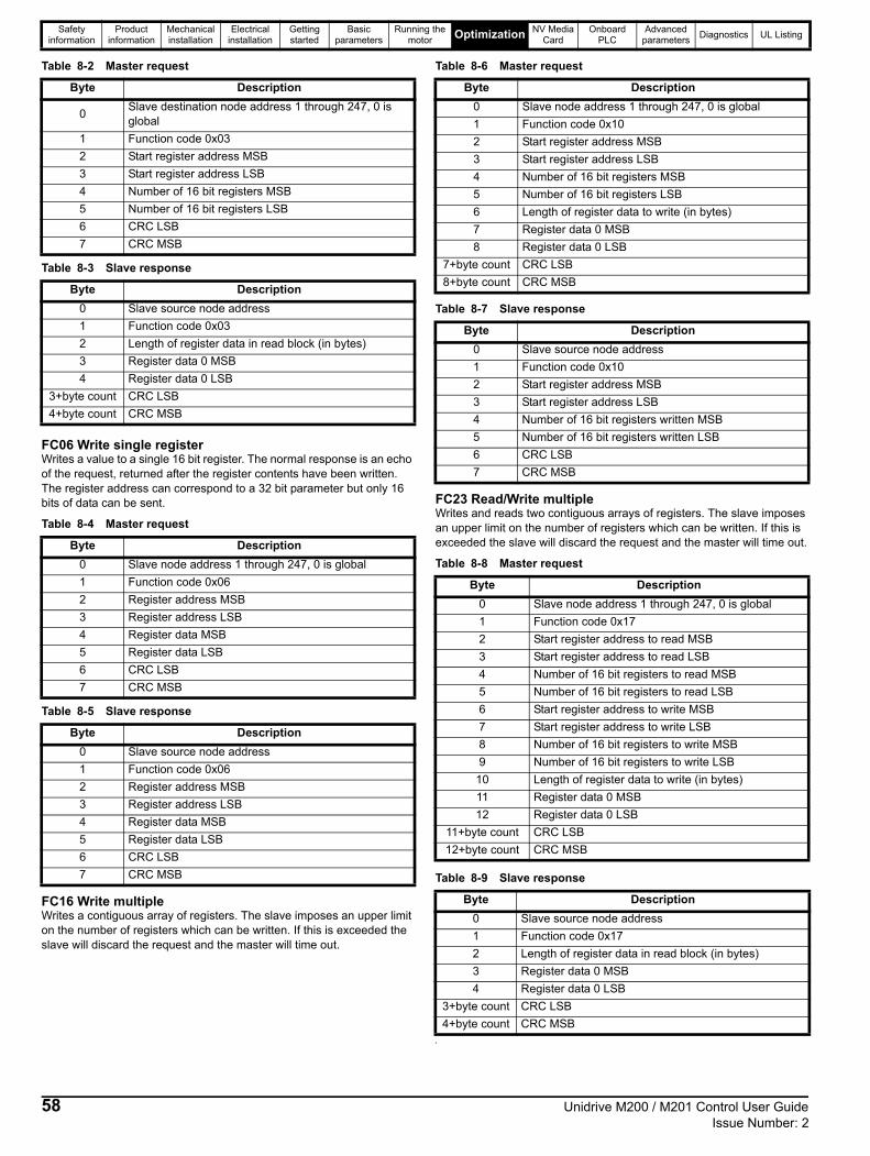
Safety information
Product information
Mechanical installation
Electrical installation
Getting started
Basic parameters
Running the motor Optimization NV Media
CardOnboard
PLCAdvanced
parametersDiagnostics UL Listing
Table 8-2 Master request
Table 8-3 Slave response
FC06 Write single registerWrites a value to a single 16 bit register. The normal response is an echo of the request, returned after the register contents have been written. The register address can correspond to a 32 bit parameter but only 16 bits of data can be sent.
Table 8-4 Master request
Table 8-5 Slave response
FC16 Write multipleWrites a contiguous array of registers. The slave imposes an upper limit on the number of registers which can be written. If this is exceeded the slave will discard the request and the master will time out.
Table 8-6 Master request
Table 8-7 Slave response
FC23 Read/Write multipleWrites and reads two contiguous arrays of registers. The slave imposes an upper limit on the number of registers which can be written. If this is exceeded the slave will discard the request and the master will time out.
Table 8-8 Master request
Table 8-9 Slave response
s
Byte Description
0Slave destination node address 1 through 247, 0 is global
1 Function code 0x03
2 Start register address MSB
3 Start register address LSB
4 Number of 16 bit registers MSB
5 Number of 16 bit registers LSB
6 CRC LSB
7 CRC MSB
Byte Description
0 Slave source node address
1 Function code 0x03
2 Length of register data in read block (in bytes)
3 Register data 0 MSB
4 Register data 0 LSB
3+byte count CRC LSB
4+byte count CRC MSB
Byte Description
0 Slave node address 1 through 247, 0 is global
1 Function code 0x06
2 Register address MSB
3 Register address LSB
4 Register data MSB
5 Register data LSB
6 CRC LSB
7 CRC MSB
Byte Description
0 Slave source node address
1 Function code 0x06
2 Register address MSB
3 Register address LSB
4 Register data MSB
5 Register data LSB
6 CRC LSB
7 CRC MSB
Byte Description
0 Slave node address 1 through 247, 0 is global
1 Function code 0x10
2 Start register address MSB
3 Start register address LSB
4 Number of 16 bit registers MSB
5 Number of 16 bit registers LSB
6 Length of register data to write (in bytes)
7 Register data 0 MSB
8 Register data 0 LSB
7+byte count CRC LSB
8+byte count CRC MSB
Byte Description
0 Slave source node address
1 Function code 0x10
2 Start register address MSB
3 Start register address LSB
4 Number of 16 bit registers written MSB
5 Number of 16 bit registers written LSB
6 CRC LSB
7 CRC MSB
Byte Description
0 Slave node address 1 through 247, 0 is global
1 Function code 0x17
2 Start register address to read MSB
3 Start register address to read LSB
4 Number of 16 bit registers to read MSB
5 Number of 16 bit registers to read LSB
6 Start register address to write MSB
7 Start register address to write LSB
8 Number of 16 bit registers to write MSB
9 Number of 16 bit registers to write LSB
10 Length of register data to write (in bytes)
11 Register data 0 MSB
12 Register data 0 LSB
11+byte count CRC LSB
12+byte count CRC MSB
Byte Description
0 Slave source node address
1 Function code 0x17
2 Length of register data in read block (in bytes)
3 Register data 0 MSB
4 Register data 0 LSB
3+byte count CRC LSB
4+byte count CRC MSB
58 Unidrive M200 / M201 Control User Guide Issue Number: 2

Safety information
Product information
Mechanical installation
Electrical installation
Getting started
Basic parameters
Running the motor Optimization NV Media
CardOnboard
PLCAdvanced
parametersDiagnostics UL Listing
8.6.7 Extended data typesStandard MODBUS registers are 16bit and the standard mapping maps a single #X.Y parameter to a single MODBUS register. To support 32 bit data types (integer and float) the MODBUS multiple read and write services are used to transfer a contiguous array of 16bit registers.
Slave devices typically contain a mixed set of 16 bit and 32 bit registers. To permit the master to select the desired 16 bit or 32 bit access the top two bits of the register address are used to indicate the selected data type.
The selection is applied for the whole block access.
The 2bit type field selects the data type according to the table below:
If a 32 bit data type is selected then the slave uses two consecutive 16 bit MODBUS registers (in 'big endian'). The master must also set the correct 'number of 16 bit registers'.
Example, read Pr 20.021 through Pr 20.024 as 32 bit parameters using FC03 from node 8:
Table 8-10 Master request
Table 8-11 Slave response
Reads when actual parameter type is different from selectedThe slave will send the least significant word of a 32 bit parameter if that parameter is read as part of a 16 bit access.
The slave will sign extend the least significant word if a 16 bit parameter is accessed as a 32 bit parameter. The number of 16 bit registers must be even during a 32 bit access.
Example, If Pr 01.028 is a 32 bit parameter with a value of 0x12345678, Pr 01.029 is a signed 16 bit parameter with a value of 0xABCD, and Pr 01.030 is a signed 16 bit parameter with a value of 0x0123.
* Bit 14 is set to allow 32 bit access.
Writes when actual parameter type is different from selectedThe slave will allow writing a 32 bit value to a 16 bit parameter as long as the 32 bit value is within the normal range of the 16 bit parameter.
The slave will allow a 16 bit write to a 32 bit parameter. The slave will sign extend the written value, therefore the effective range of this type of write will be -32768 to +32767.
Examples, if Pr 01.028 has a range of ±100000, and Pr 01.029 has a range of ±10000.
Type fieldbits 15-14
Selected data type
Comments
00 INT16 backward compatible
01 INT32
10 Float32IEEE754 standardNot supported on all slaves
11 Reserved
Byte Value Description
0 0x08 Slave destination node address
1 0x03 FC03 multiple read
2 0x47 Start register address Pr 20.021(16384 + 2021 - 1) = 18404 = 0x47E43 0xE4
4 0x00 Number of 16bit registers to readPr 20.021 through Pr 20.024 is 4x32 bit registers = 8x16 bit registers5 0x08
6 CRC LSB
7 CRC MSB
Byte Value Description
0 0x08 Slave destination node address
1 0x03 FC03 multiple read
2 0x10Length of data (bytes) = 4x32 bit registers = 16 bytes
3-6 Pr 20.021 data
7-10 Pr 20.022 data
11-14 Pr 20.023 data
15-18 Pr 20.024 data
19 CRC LSB
20 CRC MSB
NOTE
bit 15TYP1
bits 0 - 13
Type select Parameter addressX x 100+Y-1
bit 14TYP0
ReadStart
register address
Number of 16 bit registers
Response Comments
Pr 01.028 127 1 0x5678
Standard 16 bit access to a 32 bit register will return low 16 bit word of truncated data
Pr 01.028 16511* 2 0x12345678 Full 32 bit access
Pr 01.028 16511* 1 Exception 2Number of words must be even for 32 bit access
Pr 01.029 128 1 0xABCD
Standard 16 bit access to a 32 bit register will return low 16 bit word of data
Pr 01.029 16512* 2 0xFFFFABCD
32 bit access to a 16 bit register will return 32 bit sign extended data
Pr 01.030 16513* 2 0x00000123
32 bit access to a 16 bit register will return 32 bit sign extended data
Pr 01.028 to
Pr 01.029127 2
0x5678, 0xABCD
Standard 16 bit access to a 32 bit register will return low 16 bit word of truncated data
Pr 01.028 to
Pr 01.029 16511* 4
0x12345678, 0xFFFFABCD
Full 32 bit access
Unidrive M200 / M201 Control User Guide 59Issue Number: 2

Safety information
Product information
Mechanical installation
Electrical installation
Getting started
Basic parameters
Running the motor Optimization NV Media
CardOnboard
PLCAdvanced
parametersDiagnostics UL Listing
* Bit 14 is set to allow 32 bit access
8.6.8 ExceptionsThe slave will respond with an exception response if an error is detected in the master request. If a message is corrupted and the frame is not received or the CRC fails then the slave will not issue an exception. In this case the master device will time out. If a write multiple (FC16 or FC23) request exceeds the slave maximum buffer size then the slave will discard the message. No exception will be transmitted in this case and the master will time out.
Exception message formatThe slave exception message has the following format.
Exception codesThe following exception codes are supported.
Parameter over range during block write FC16The slave processes the write block in the order the data is received. If a write fails due to an out of range value then the write block is terminated. However, the slave does not raise an exception response, rather the error condition is signalled to the master by the number of successful writes field in the response.
Parameter over range during block read/write FC23There will be no indication that there has been a value out of range during a FC23 access.
8.6.9 CRCThe CRC is a 16bit cyclic redundancy check using the standard CRC-16 polynomial x16 + x15 + x2 + 1. The 16 bit CRC is appended to the message and transmitted LSB first.
The CRC is calculated on ALL the bytes in the frame.
8.6.10 Device compatibility parametersAll devices have the following compatibility parameters defined:
WriteStart
register address
Number of 16 bit registers
Data Comments
Pr 01.028 127 1 0x1234
Standard 16 bit write to a 32bit register. Value written = 0x00001234
Pr 01.028 127 1 0xABCD
Standard 16 bit write to a 32 bit register. Value written = 0xFFFFABCD
Pr 01.028 16511 2 0x00001234Value written = 0x00001234
Pr 01.029 128 1 0x0123Value written = 0x0123
Pr 01.029 16512 2 0x00000123Value written = 0x00000123
Byte Description
0 Slave source node address
1 Original function code with bit 7 set
2 Exception code
3 CRC LSB
4 CRC MSB
Code Description
1 Function code not supported
2Register address out of range, or request to read too many registers
Parameter Description
Device ID Unique device identification code
Minimum slave response time
The minimum delay between the end of a message from the master and the time at which the master is ready to receive a response from the slave. Refer to para 11-26
Maximum slave response time
When global addressing, the master must wait for this time before issuing a new message. In a network of devices, the slowest time must be used
Maximum baud rate
32 bit float data type supported
If this data type is not supported then an over range error will be raised if this data type is used
Maximum buffer size Determines the maximum block size.
60 Unidrive M200 / M201 Control User Guide Issue Number: 2

Safety information
Product information
Mechanical installation
Electrical installation
Getting started
Basic parameters
Running the motor
OptimizationNV Media
CardOnboard
PLCAdvanced
parametersDiagnostics UL Listing
9 NV Media Card
9.1 IntroductionThe Non-Volatile Media Card feature enables simple configuration of parameters, parameter back-up and drive cloning using an SD card.
The SD card can be used for:
• Parameter copying between drives• Saving drive parameter sets
The NV Media Card (SD card) is located in the AI-Backup adaptor.
The card is not hot swappable, but the AI-Backup adaptor is “hot swapped” only when the five unit LEDs on the display are not flashing. The unit LEDs flash during the data transfer.
Figure 9-1 Installation of the SD card
1. Installing the SD card
A flat bladed screwdriver or similar tool is required in order to insert / remove the SD card fully into the AI-Backup adaptor.
Before inserting / removing the SD card into / from the AI-Backup adaptor, the AI-Backup adaptor must be removed from the drive.
The drive supports SD cards formatted with the FAT32 file system only.
9.2 SD card supportAn SD memory card can be inserted in the AI-Backup Adaptor in order to transfer data to the drive, however the following limitations should be noted:
If a parameter from the source drive does not exist in the target drive then no data is transferred for that parameter.
If the data for the parameter in the target drive is out of range then the data is limited to the range of the target parameter.
If the target drive has a different rating to the source drive then the normal rules for this type of transfer apply as described later.
No checking is possible to determine if the source and target product types are the same, and so no warning is given if they are different.
If an SD card is used then the drive will recognise the following file types through the drive parameter interface.
These files can be created on a card by the drive and then transferred to any other drive including derivatives. If the Drive Derivative (11.028) is different between the source and target drives then the data is transferred but a C.Pr trip is initiated.
It is possible for other data to be stored on the card, but this should not be stored in the <MCDF> folder and it will not be visible via the drive parameter interface.
9.2.1 Changing the drive modeIf the source drive mode is different from the target drive mode then the mode will be changed to the source drive mode before the parameters are transferred. If the required drive mode is outside the allowed range for the target then a C.typ trip is initiated and no data is transferred.
9.2.2 Different voltage ratingsIf the voltage rating of the source and target drives is different then all parameters except those that are rating dependent (i.e. attribute RA=1) are transferred to the target drive. The rating dependent parameters are left at their default values. After the parameters have been transferred and saved to non-volatile memory a C.rtg trip is given as a warning. The table below gives a list of the rating dependent parameters.
9.2.3 Different option modules installed If the option module ID code (15.001) is different for any option module installed to the source drive compared to the destination drive, then the parameters for the set-up for that option module are not transferred, but and are instead set to their default values. After the parameters have been transferred and saved to non-volatile memory, a C.OPt trip is given as a warning.
File Type Description
Parameter fileA file that contains all clonable user save parameters from the drive menus (1 to 30) in difference from default format
Macro fileThe same as a parameter file, but defaults are not loaded before the data is transferred from the card
1
NOTE
NOTE
Parameters
Standard Ramp Voltage (02.008)
Motoring Current Limit (04.005)
M2 Motoring Current Limit (21.027)
Regenerating Current Limit (04.006)
M2 Regenerating Current Limit (21.028)
Symmetrical Current Limit (04.007)
M2 Symmetrical Current Limit (21.029)
User Current Maximum Scaling (04.024)
Motor Rated Current (05.007)
M2 Motor Rated Current (21.007)
Motor Rated Voltage (05.009)
M2 Motor Rated Voltage (21.009)
Motor Rated Power Factor (05.010)
M2 Motor Rated Power Factor (21.010)
Stator Resistance (05.017)
M2 Stator Resistance (21.012)
Maximum Switching Frequency (05.018)
Transient Inductance /Ld (05.024)
M2 Transient Inductance /Ld (21.014)
Stator Inductance (05.025)
M2 Stator Inductance (21.024)
Injection Braking Level (06.006)
Supply Loss Detection Level (06.048)
Unidrive M200 / M201 Control User Guide 61Issue Number: 2

Safety information
Product information
Mechanical installation
Electrical installation
Getting started
Basic parameters
Running the motor
OptimizationNV Media
CardOnboard
PLCAdvanced
parametersDiagnostics UL Listing
9.2.4 Different current ratingsIf any of the current rating parameters (Maximum Heavy Duty Rating (Pr 77), Maximum Rated Current (11.060) or Full Scale Current Kc (11.061)) are different between the source and target then all parameters are still written to the target drive, but some may be limited by their allowed range. To give similar performance in the target compared to the source drive the frequency and current controller gains are modified as shown below. Note that this does not apply if the file identification number is larger than 500.
9.2.5 Different variable maximumsIt should be noted that if ratings of the source and target drives are different, it is possible that some parameters with variable maximums may be limited and not have the same values as in the source drive.
9.2.6 Macro filesMacro files are created in the same way as parameter files except that NV Media Card Create Special File (11.072) must be set to 1 before the file is created on the NV media card. NV Media Card Create Special File (11.072) is set to zero after the file has been created or the transfer fails. When a macro file is transferred to a drive the drive mode is not changed even if the actual mode is different to that in the file and defaults are not loaded before the parameters are copied from the file to the drive.
The table below gives a summary of the values used in Pr 00 for NV media card operations. The yyy represents the file identification number.
Table 9-1 Functions in Pr 00
9.2.7 Writing to the NV Media Card4yyy - Writes defaults differences to the NV Media Card
The data block only contains the parameter differences from the last
time default settings were loaded.
All parameters except those with the NC (Not copied) coding bit set are
transferred to the NV Media Card. In addition to these parameters all
menu 20 parameters (except Pr 20.000), can be transferred to the NV
Media Card.
Writing a parameter set to the NV Media Card (Pr 30 =
Prog (2))
Setting Pr 30 to Prog (2) and resetting the drive will save the
parameters to the NV Media Card, i.e. this is equivalent to writing 4001
to Pr 00. All NV Media Card trips apply. If the data block already
exists it is automatically overwritten. When the action is complete this
parameter is automatically reset to NonE (0).
9.2.8 Reading from the NV Media Card6yyy - Reading from NV Media Card
When the data is transferred back to the drive, using 6yyy in Pr 00,
it is transferred to the drive RAM and the EEPROM. A parameter save is
not required to retain the data after-power down. Set up data for any
option module installed stored on the card are transferred to the drive. If
the option module installed is different between source and
destination drives, the menu for the option module slot where the
option module category is different is not updated from the card and
will contain its default values after the copying action. The drive will
produce a 'C.OPt' trip if the option module installed to the source
and the destination drives are different. If the data
is being transferred to the drive with different voltage or current rating a
'C.rtg' trip will occur.
The following drive rating dependant parameters (RA coding bit set) will
not be transferred to the destination drive by a NV Media Card when the
Gains Multiplier
Frequency Controller Proportional Gain Kp1 (03.010)
Frequency Controller Integral Gain Ki1 (03.011)
Frequency Controller Proportional Gain Kp2 (03.013)
Frequency Controller Integral Gain Ki2 (03.014)
M2 Frequency Controller Proportional Gain Kp (21.017)
M2 Frequency Controller Integral Gain Ki (21.018)
Current Controller Kp Gain (04.013)
Current Controller Ki Gain (04.014)
M2 Current Controller Kp Gain (21.022)
M2 Current Controller Ki Gain (21.023)
[Source Full Scale Current Kc (11.061)] /
[Target Full Scale Current Kc (11.061)]
Value Action
2001
Transfer the drive parameters to parameter file 001 and sets the block as bootable.This will include the parameters from any attached option module.
4yyyTransfer the drive parameters to parameter file yyy. This will include the parameters from any attached option module.
6yyy Load the drive parameters from parameter file yyy
7yyy Erase file yyy.
8yyy
Compare the data in the drive with the file yyy. The data in the drive is compared to the data in the file yyy. If the files are the same then Pr 00 is simply reset to 0 when the compare is complete. If the files are different a Card Compare trip is initiated. All other NV media card trips also apply.
9555 Clear the warning suppression flag.
9666 Set the warning suppression flag.
9777 Clear the read-only flag.
9888 Set the read-only flag.
62 Unidrive M200 / M201 Control User Guide Issue Number: 2

Safety information
Product information
Mechanical installation
Electrical installation
Getting started
Basic parameters
Running the motor
OptimizationNV Media
CardOnboard
PLCAdvanced
parametersDiagnostics UL Listing
voltage rating of the destination drive is different from the source drive
and the file is a parameter file.
However, drive rating dependent parameters will be transferred if only
the current rating is different. If drive rating dependant parameters are
not transferred to the destination drive they will contain their default
values.
Pr 02.008 Standard Ramp Voltage
Pr 04.005 to Pr 04.007 and Pr 21.027 to Pr 21.029 Motoring Current Limits
Pr 04.024, User Current Maximum Scaling
Pr 04.041 User Over Current Trip Level
Pr 05.007, Pr 21.007 Rated Current
Pr 05.009, Pr 21.009 Rated Voltage
Pr 05.010, Pr 21.010 Rated Power Factor
Pr 05.017, Pr 21.012 Stator Resistance
Pr 05.018 Maximum Switching Frequency
Pr 05.024, Pr 21.014 Transient Inductance
Pr 05.025, Pr 21.024 Stator Inductance
Pr 06.006 Injection Braking Level
Pr 06.048 Supply Loss Detection Level
Pr 06.073 Braking IGBT Lower Threshold
Pr 06.074 Braking IGBT Upper Threshold
Pr 06.075 Low Voltage Braking IGBT Threshold
Reading a parameter set from the NV Media Card (Pr 30
= rEAd (1))
Setting Pr 30 to rEAd (1) and resetting the drive will transfer the
parameters from the card into the drive parameter set and the drive
EEPROM, i.e. this is equivalent to writing 6001 to Pr 00.
All NV Media Card trips apply. Once the parameters are successfully
copied this parameter is automatically reset to NonE (0). Parameters are
saved to the drive EEPROM after this action is complete.
9.2.9 Auto saving parameter changes (Pr 30 = Auto (3))This setting causes the drive to automatically save any changes made to
menu 0 parameters on the drive to the NV Media Card. The latest menu
0 parameter set in the drive is therefore always backed up on the NV
Media Card. Changing Pr 30 to Auto (3) and resetting the drive will
immediately save the complete parameter set from the drive to the card,
i.e. all parameters except parameters with the NC coding bit set. Once
the whole parameter set is stored only the individual modified menu 0
parameter setting is updated.
Advanced parameter changes are only saved to the NV Media Card
when Pr 00 is set to 'SAVE' or a 1001 and the drive reset.
All NV Media Card trips apply. If the data block already contains information it is automatically overwritten.
If the card is removed when Pr 30 is set to 3, Pr 30 is then
automatically set to NonE (0).
When a new NV Media Card is installed Pr 30 must be set back to
Auto (3) by the user and the drive reset so the complete parameter set is
rewritten to the new NV Media Card if auto mode is still required.
When Pr 30 is set to Auto (3) and the parameters in the drive are
saved, the NV Media Card is also updated, and therefore the NV Media
Card becomes a copy of the drives stored configuration.
At power up, if Pr 30 is set to Auto (3), the drive will save the
complete parameter set to the NV Media Card. The 5 unit LEDs will flash during this operation. This is done to ensure that if a user
puts a new NV Media Card in during power down the new NV Media
Card will have the correct data.
When Pr 30 is set to Auto (3) the setting of Pr 30 itself is saved
to the drive EEPROM but not the NV Media Card.
9.2.10 Booting up from the NV Media Card on everypower up (Pr 30 = boot (4))When Pr 30 is set to boot (4) the drive operates the same as Auto
mode except when the drive is powered-up. The parameters on the NV
Media Card will be automatically transferred to the drive at power up if
the following are true:
• A card is inserted in the drive• Parameter data block 1 exists on the card• The data in block 1 is type 1 to 4 (as defined in Pr 11.038)• Pr 30 on the card set to boot (4)The 5 unit LEDs will flash during this operation. If the drive mode is different from that on the card, the drive gives a 'C.tyP' trip and the data is not transferred.
If 'boot' mode is stored on the copying NV Media Card this makes the
copying NV Media Card the master device. This provides a very fast and
efficient way of re-programming a number of drives.
'boot' mode is saved to the card, but when the card is read, the value of
Pr 30 is not transferred to the drive.
9.2.11 Booting up from the NV Media Card on everypower up (Pr 00 = 2001)It is possible to create a bootable parameter data block by setting
Pr 00 to 2001 and initiating a drive reset. This data block is created
in one operation and is not updated when further parameter changes are
made.
Setting Pr 00 to 2001 will overwrite the data block 1 on the card if it
already exists.
9.2.12 8yyy - Comparing the drive full parameter set with the NV Media Card valuesSetting 8yyy in Pr 00, will compare the NV Media Card file with the
data in the drive. If the compare is successful Pr 00 is simply set to 0. If the compare fails a 'C.cPr' trip is initiated.
9.2.13 7yyy - Erasing data from the NV MediaCard valuesData can be erased from the NV Media Card either one block at a time
or all blocks in one go.
• Setting 7yyy in Pr 00 will erase NV Media Card data block yyy
9.2.14 9666 / 9555 - Setting and clearing the NV Media Card warning suppression flagIf the option module installed to the source and destination drive are
different the drive will produce a 'C.OPt' trip.
If the data is being transferred to a drive of a different voltage or current
rating a 'C.rtg' trip will occur. It is possible to suppress these trips
NOTE
Unidrive M200 / M201 Control User Guide 63Issue Number: 2

Safety information
Product information
Mechanical installation
Electrical installation
Getting started
Basic parameters
Running the motor
OptimizationNV Media
CardOnboard
PLCAdvanced
parametersDiagnostics UL Listing
by setting the warning suppression flag. If this flag is set the drive will not
trip if the option module or drive ratings are different between the
source and destination drives. The option module or rating dependent
parameters will not be transferred.
• Setting 9666 in Pr 00 will set the warning suppression flag• Setting 9555 in Pr 00 will clear the warning suppression flag
9.2.15 9888 / 9777 - Setting and clearing the NV Media Card read only flagThe NV Media Card may be protected from writing or erasing by setting
the read only flag. If an attempt is made to write or erase a data block
when the read only flag is set, a 'C.rdo' trip is initiated. When
the read only flag is set only codes 6yyy or 9777 are effective.
• Setting 9888 in Pr 00 will set the read only flag• Setting 9777 in Pr 00 will clear the read only flag
9.3 NV Media Card parametersTable 9-2 Key to parameter table coding
This parameter shows the number of the data block last transferred from an SD card to the drive. If defaults are subsequently reloaded this parameter is set to 0.
This parameter should have the data block number which the user would like the information displayed in Pr 11.038, Pr 11.039.
Displays the type of data block selected with Pr 11.037.
Displays the version number of the file selected in Pr 11.037.
9.4 NV Media Card tripsAfter an attempt to read, write or erase data from a NV Media Card a trip is initiated if there has been a problem with the command.
See Chapter 12 Diagnostics on page 129 for more information on NV Media Card trips.
9.5 Data block header informationEach data block stored on a NV Media Card has header information detailing the following:
• NV Media Card File Number (11.037)• NV Media Card File Type (11.038)• NV Media Card File Version (11.039)The header information for each data block which has been used can be viewed in Pr 11.038 to Pr 11.039 by increasing or decreasing the data block number set in Pr 11.037. If there is no data on the card Pr 11.037 can only have a value of 0.
RW Read / Write ND No default value
RO Read only NC Not copied
Num Number parameter PT Protected parameter
Bit Bit parameter RA Rating dependant
Txt Text string US User save
Bin Binary parameter PS Power-down save
FI Filtered DE Destination
11.036 NV Media Card File Previously Loaded
RO Num NC PT
0 to 999 0
11.037 NV Media Card File Number
RW Num
0 to 999 0
11.038 NV Media Card File Type
RO Txt ND NC PT
0 to 2 0
Pr 11.038 String Type / mode
0 None No file selected
1 Open-loop Open loop mode parameter file
2 RFC-A RFC-A mode parameter file
11.039 NV Media Card File Version
RO Num ND NC PT
0 to 9999 0
11.042 30 Parameter Cloning
RW Txt NC US
NonE (0), rEAd (1), Prog
(2), Auto (3), boot (4)
0
64 Unidrive M200 / M201 Control User Guide Issue Number: 2

Safety information
Product information
Mechanical installation
Electrical installation
Getting started
Basic parameters
Running the motor
OptimizationNV Media
CardOnboard
PLCAdvanced
parametersDiagnostics UL Listing
10 Onboard PLC
10.1 Onboard PLC and Machine Control Studio
The drive has the ability to store and execute a 16 kB (less 4 kB of proxy) Onboard PLC user program without the need for additional hardware in the form of an option module.
Machine Control Studio is an IEC61131-3 development environment designed for use with Unidrive M and compatible application modules. Machine Control Studio is based on CODESYS from 3S-Smart Software Solutions.
All of the programming languages defined in the IEC standard IEC 61131-3 are supported in the Machine Control Studio development environment.
• ST (Structured text)• LD (Ladder diagram)• FBD (Function block diagram) • IL (Instruction list)• SFC (Sequential function chart) • CFC (Continuous Function Chart). CFC is an extension to the
standard IEC programming languages
Machine Control Studio provides a complete environment for the development of user programs. Programs can be created, compiled and downloaded to a Unidrive M for execution, via the communications port on the front of the drive. The run-time operation of the compiled program on the target can also be monitored using Machine Control Studio and facilities are provided to interact with the program on the target by setting new values for target variables and parameters.
The Onboard PLC and Machine Control Studio form the first level of functionality in a range of programmable options for Unidrive M.
Machine Control Studio can be downloaded from www.controltechniques.com.
See the Machine Control Studio help file for more information regarding using Machine Control Studio, creating user programs and downloading user programs to the drive.
10.2 BenefitsThe combination of the Onboard PLC and Machine Control Studio, means that the drive can replace nano and some micro PLCs in many applications
Machine Control Studio benefits from access to the standard CODESYS function and function block libraries as well as those from third parties. Functions and function blocks available as standard in Machine Control Studio include, but not limited to, the following:
• Arithmetic blocks• Comparison blocks• Timers• Counters• Multiplexers• Latches• Bit manipulation
Typical applications for the Onboard PLC include:
• Ancillary pumps• Fans and control valves• Interlocking logic• Sequence routines• Custom control words.
10.3 FeaturesThe Unidrive M Onboard PLC user program has the following features:
10.3.1 TasksThe Onboard PLC allows use of two tasks.
• Clock: A high priority real time task. The clock task interval can be set from 16 ms to 262 s in multiples of 16 ms. The parameter Onboard User Program: Clock Task Time Used (11.051) shows the percentage of the available time used by clock task. A read or write of a drive parameter by the user program takes a finite period of time. It is possible to select up to 10 parameters as fast access parameter which reduced the amount of time it takes for the user program to read from or write to a drive parameter. This is useful when using a clock task with a fast update rate as selecting a parameter for fast access reduces the amount of the clock task resource required to access parameters.
• Freewheeling: A non-real time background task. The freewheeling task is scheduled for a short period once every 256 ms. The time for which the task is scheduled will vary depending on the loading of the drive's processor. When scheduled, several scans of the user program may be performed. Some scans may execute in microseconds. However, when the main drive functions are scheduled there will be a pause in the execution of the program causing some scans to take many milliseconds. The parameter Onboard User Program: Freewheeling Tasks Per Second (11.050) shows the number of times the freewheeling task has started per second.
10.3.2 VariablesThe Onboard PLC supports the use of variables with the data types of Boolean, integer (8 bit, 16 bit and 32 bit, signed and unsigned), floating point (64 bit only), strings and time.
10.3.3 Custom menuMachine Control Studio can construct a custom drive menu to reside in menu 30 on the drive. The following properties of each parameter can be defined using Machine Control Studio:
• Parameter name• Number of decimal places• The units for the parameter to be display on the keypad.• The minimum, maximum and default values• Memory handling (i.e. power down save, user save or volatile)• Data type. The drive provides a limited set of 1 bit, 8 bit, 16 bit and
32 bit integer parameters to create the customer menu.
Parameters in this customer menu can be accessed by the user program and will appear on the keypad.
10.3.4 LimitationsThe Onboard PLC user program has the following limitations:
• The flash memory allocated to the Onboard PLC is 16 kB which includes the user program and its header which results in a maximum user program size of about 12 kB
• The Onboard PLC is provided with 2 kB of RAM. • The drive is rated for 100 program downloads. This limitation is
imposed by the flash memory used to store the program within the drive.
• There is only one real-time task with a minimum period of 16 ms.• The freewheeling background task runs at a low priority. The drive is
prioritized to perform the clock task and its major functions first, e.g. motor control, and will use any remaining processing time to execute the freewheeling task as a background activity. As the drive's processor becomes more heavily loaded, less time is spent executing the freewheeling task.
• Breakpoints, single stepping and online program changes are not possible.
• The Graphing tool is not supported.• The variable data types REAL (32 bit floating point), LWORD (64 bit
integer) and WSTRING (Unicode string), and retained variables are not supported.
Unidrive M200 / M201 Control User Guide 65Issue Number: 2

Safety information
Product information
Mechanical installation
Electrical installation
Getting started
Basic parameters
Running the motor
OptimizationNV Media
CardOnboard
PLCAdvanced
parametersDiagnostics UL Listing
10.4 Onboard PLC parametersThe following parameters are associated with the Onboard PLC user program.
This parameter stops and starts the user program.
0 - Stop the User Program
The onboard user program is stopped.
1 - Run the User Program
The user program will execute. Background task starts from the beginning.
This parameter is read-only and indicates the status of the user program in the drive. The user program writes the value to this parameter.
0: Stopped
1: Running
2: Exception
3: No user program present
This parameter holds the number of times an Onboard PLC user program download has taken place and is 0 on dispatch from the factory. The drive is rated for one hundred program downloads. This parameter is not altered when defaults are loaded.
This parameter shows the number of times the freewheeling task has started per second.
This parameter shows the percentage of the available time used by the user program clock task.
This parameter shows the interval at which the clock task is scheduled to run at in ms.
10.5 Onboard PLC tripsIf the drive detects an error in the user program it will initiate a User Program trip. The sub-trip number for the User Program trip details the reason for the error. See Chapter 12 Diagnostics on page 137 for more information on the User Program trip.11.047 Onboard User Program: Enable
RW Txt US
Stop (0) or Run (1) Run (1)
11.048 Onboard User Program: Status
RO Txt NC PT
-2147483648 to 2147483647
11.049 Onboard User Program: Programming Events
RO Uni NC PT PS
0 to 65535
11.050Onboard User Program: Freewheeling Tasks Per Second
RO Uni NC PT
0 to 65535
11.051 Onboard User Program: Clock Task Time Used
RO NC PT
0.0 to 100.0 %
11.055Onboard User Program: Clock Task Scheduled Interval
RO NC PT
0 to 262128 ms
66 Unidrive M200 / M201 Control User Guide Issue Number: 2

Safety information
Product information
Mechanical installation
Electrical installation
Getting started
Basic parameters
Running the motor
OptimizationNV Media
CardOnboard
PLCAdvanced
parametersDiagnostics UL Listing
11 Advanced parametersThis is a quick reference to all parameters in the drive showing units, ranges limits etc, with block diagrams to illustrate their function. Full descriptions of the parameters can be found in the Parameter Reference Guide.
Table 11-1 Menu descriptions
* Only displayed when the option module is installed.
Operation mode abbreviations:
Open-loop: Sensorless control for induction motors
RFC-A: Asynchronous Rotor Flux Control for induction motors
Default abbreviations:
Standard default value (50 Hz AC supply frequency)
USA default value (60 Hz AC supply frequency)
Parameter numbers shown in brackets ... are the equivalent Menu 0 parameters. Some Menu 0 parameters appear twice since their function depends on the operating mode.
In some cases, the function or range of a parameter is affected by the setting of another parameter. The information in the lists relates to the default condition of any parameters affected in this way.
Table 11-2 Key to parameter table coding
These advanced parameters are listed for reference purposes only. The lists in this chapter do not include sufficient information for adjusting these parameters. Incorrect adjustment can affect the safety of the system, and damage the drive and or external equipment. Before attempting to adjust any of these parameters, refer to the Parameter reference guide.
Menu Description
0Commonly used basic set up parameters for quick / easy programming
1 Frequency reference
2 Ramps
3 Frequency control
4 Torque and current control
5 Motor control
6 Sequencer and clock
7 Analog I/O
8 Digital I/O
9 Programmable logic, motorized pot, binary sum, timers
10 Status and trips
11 Drive set-up and identification, serial communications
12 Threshold detectors and variable selectors
14 User PID controller
15 Option module slot 1 set-up menu
18 General option module application menu 1
20 General option module application menu 2
21 Second motor parameters
22 Menu 0 set-up
24 Option module slot 1 application menu
Slot 1 Slot 1 option menus*
WARNING
Coding Attribute
RW Read/Write: can be written by the user
RO Read only: can only be read by the user
Bit 1 bit parameter. ‘On’ or ‘Off’ on the display
Num Number: can be uni-polar or bi-polar
Txt Text: the parameter uses text strings instead of numbers.
Bin Binary parameter
IP IP Address parameter
Mac Mac Address parameter
Date Date parameter
Time Time parameter
Chr Character parameter
FIFiltered: some parameters which can have rapidly changing values are filtered when displayed on the drive keypad for easy viewing.
DEDestination: This parameter selects the destination of an input or logic function.
RA
Rating dependent: this parameter is likely to have different values and ranges with drives of different voltage and current ratings. Parameters with this attribute will be transferred to the destination drive by non-volatile storage media when the rating of the destination drive is different from the source drive and the file is a parameter file. However, the values will be transferred if only the current rating is different and the file is a difference from default type file.
NDNo default: The parameter is not modified when defaults are loaded
NCNot copied: not transferred to or from non-volatile media during copying.
PT Protected: cannot be used as a destination.
USUser save: parameter saved in drive EEPROM when the user initiates a parameter save.
PSPower-down save: parameter automatically saved in drive EEPROM when the under volts (UV) state occurs.
NOTE
Unidrive M200 / M201 Control User Guide 67Issue Number: 2

Safety information
Product information
Mechanical installation
Electrical installation
Getting started
Basic parameters
Running the motor
OptimizationNV Media
CardOnboard
PLCAdvanced
parametersDiagnostics UL Listing
Table 11-3 Feature look-up table
Features Related parameters (Pr)
Acceleration rates 02.010 02.011 to 02.019 02.032 02.033 02.034 02.002
Analog I/O Menu 7
Analog input 1 07.001 07.007 07.008 07.009 07.010 07.028 07.051 07.030 07.061 07.062 07.063 07.064
Analog input 2 07.002 07.011 07.012 07.013 07.014 07.031 07.052 07.065 07.066 07.067 07.068
Analog output 1 07.019 07.020 07.055 07.099
Analog reference 1 01.036 07.010 07.001 07.007 07.008 07.009 07.028 07.051 07.030 07.061 07.062 07.063 07.064
Analog reference 2 01.037 07.014 01.041 07.002 07.011 07.012 07.013 07.032 07.031 07.065 07.066 07.067 07.068
Application menu Menu 18 Menu 20
At frequency indicator bit 03.006 03.007 03.009 10.006 10.005 10.007
Auto reset 10.034 10.035 10.036 10.001
Autotune 05.012 05.017 05.021 05.024 05.025 05.010 05.029 05.030 05.062 05.063 05.059 05.060
Binary sum 09.029 09.030 09.031 09.032 09.033 09.034
Bipolar reference 01.010
Brake control 12.040 to 12.047 12.050 12.051
Braking 10.011 10.010 10.030 10.031 06.001 02.004 02.002 10.012 10.039 10.040 10.061
Catch a spinning motor 06.009 05.040
Coast to stop 06.001
Copying 11.042 11.036 to 11.039
Cost - per kWh electricity 06.016 06.017 06.024 06.025 06.026 06.027
Current controller 04.013 04.014
Current feedback 04.001 04.002 04.017 04.004 04.020 04.024 04.026 10.008 10.009 10.017
Current limits 04.005 04.006 04.007 04.018 04.015 04.019 04.016 05.007 05.010 10.008 10.009 10.017
DC bus voltage 05.005 02.008
DC injection braking 06.006 06.007 06.001
Deceleration rates 02.020 02.021 to 02.029 02.004 02.035 to 02.037 02.002 02.008 06.001 10.030 10.031 10.039 02.009
Defaults 11.043 11.046
Digital I/O Menu 8
Digital I/O read word 08.020
Digital I/O T10 08.001 08.011 08.021 08.031 08.081 08.091 08.121
Digital Input T11 08.002 08.012 08.022 08.082 08.122
Digital Input T12 08.003 08.013 08.023 08.083 08.123
Digital input T13 08.004 08.014 08.024 08.084 08.124
Digital input T14 08.005 08.015 08.025 08.035 08.085 08.125
Direction 10.013 06.030 06.031 01.003 10.014 02.001 03.002 08.003 08.004 10.040
Drive active 10.002 10.040
Drive derivative 11.028
Drive OK 10.001 08.028 08.008 08.018 10.036 10.040
Dynamic performance 05.026
Dynamic V/F 05.013
Enable 06.015 06.038
Estimated frequency 03.002 03.003 03.004
External trip 10.032
Fan speed 06.045
Field weakening - induction motor
05.029 05.030 01.006 05.028 05.062 05.063
Filter change 06.019 06.018 06.021 06.022 06.023
Firmware version 11.029 11.035
68 Unidrive M200 / M201 Control User Guide Issue Number: 2

Safety information
Product information
Mechanical installation
Electrical installation
Getting started
Basic parameters
Running the motor
OptimizationNV Media
CardOnboard
PLCAdvanced
parametersDiagnostics UL Listing
Frequency controller 03.010 to 03.017
Frequency reference selection
01.014 01.015
Frequency slaving 03.001 03.013 03.014 03.015 03.016 03.017 03.018
Hard frequency reference 03.022 03.023
Heavy duty rating 05.007 11.032
High stability space vector modulation
05.019
I/O sequencer 06.004 06.030 06.031 06.032 06.033 06.034 06.042 06.043 06.041
Inertia compensation 02.038 04.022 03.018
Jog reference 01.005 02.019 02.029
Keypad reference 01.017 01.014 01.043 01.051 06.012 06.013
Limit switches 06.035 06.036
Line power supply loss 06.003 10.015 10.016 05.005 06.046 06.048 06.051
Logic function 1 09.001 09.004 09.005 09.006 09.007 09.008 09.009 09.010
Logic function 2 09.002 09.014 09.015 09.016 09.017 09.018 09.019 09.020
Maximum speed 01.006
Menu 0 set-up Menu 22
Minimum speed 01.007 10.004
Motor map 05.006 05.007 05.008 05.009 05.010 05.011
Motor map 2 Menu 21 11.045
Motorized potentiometer 09.021 09.022 09.023 09.024 09.025 09.026 09.027 09.028 09.003
NV media card 11.036 to 11.039 11.042
Offset reference 01.004 01.038 01.009
Open loop vector mode 05.014 05.017 05.088
Operating mode 11.031 05.014
Output 05.001 05.002 05.003 05.004
Over frequency threshold 03.008
Over modulation enable 05.020
PID controller Menu 14
Power up parameter 11.022
Preset speeds 01.015 01.021 to 01.028 01.014 01.042 01.045 to 01.047 01.050
Programmable logic Menu 9
Ramp (accel / decel) mode 02.004 02.008 06.001 02.002 02.003 10.030 10.031 10.039
Reference selection 01.014 01.015 01.049 01.050 01.001
Regenerating 10.010 10.011 10.030 10.031 06.001 02.004 02.002 10.012 10.039 10.040
Relay output 08.008 08.018 08.028
Reset 10.001 10.033 10.034 10.035 10.036 10.038
RFC mode 05.040
S ramp 02.006 02.007
Sample rates 05.018
Security code 11.030 11.044
Serial comms 11.020 11.023 to 11.027 11.099
Skip references 01.029 01.030 01.031 01.032 01.033 01.034 01.035
Slip compensation 05.027 05.008 05.033 05.036 05.084
Status word 10.040
Supply 05.005 06.003 06.046 06.048 06.051 06.058 06.059
Switching frequency 05.018 05.035 05.038 07.034 07.035
Features Related parameters (Pr)
Unidrive M200 / M201 Control User Guide 69Issue Number: 2
Safety information
Product information
Mechanical installation
Electrical installation
Getting started
Basic parameters
Running the motor
OptimizationNV Media
CardOnboard
PLCAdvanced
parametersDiagnostics UL Listing
11.1 Parameter ranges and Variable minimum/maximums:Some parameters in the drive have a variable range with a variable minimum and a variable maximum value which is dependent on one of the following:
• The settings of other parameters• The drive rating• The drive mode• Combination of any of the above
The tables below give the definition of variable minimum/maximum and the maximum range of these.
Thermal protection - drive 05.018 05.035 07.004 07.005 07.035 10.018
Thermal protection - motor 04.015 05.007 04.019 04.016 04.025 08.035
Thermistor input 07.046 07.047 07.048 07.049 07.050 08.035
Threshold detector 1 12.001 12.003 to 12.007
Threshold detector 2 12.002 12.023 to 12.027
Time - filter change 06.019 06.018 06.021 06.022 06.023
Time - powered up log 06.020 06.019 06.017 06.018 06.084
Time - run log 06.019 06.017 06.018 06.084
Torque 04.003 04.026 05.032
Torque mode 04.008 04.011
Trip detection 10.037 10.038 10.020 to 10.029
Trip log 10.020 to 10.029 10.041 to 10.060 10.070 to 10.079
Under voltage 05.005 10.016 10.015 10.068
V/F mode 05.015 05.014
Variable selector 1 12.008 to 12.016
Variable selector 2 12.028 to 12.036
Voltage controller 05.031
Voltage mode 05.014 05.017 05.015
Voltage rating 11.033 05.009 05.005
Voltage supply 06.046 05.005
Warning 10.019 10.012 10.017 10.018 10.040
Zero frequency indicator bit 03.005 10.003
Features Related parameters (Pr)
VM_AC_VOLTAGE Range applied to parameters showing AC voltage
Units V
Range of [MIN] 0
Range of [MAX] 0 to 930
DefinitionVM_AC_VOLTAGE[MAX] is drive voltage rating dependent. See Table 11-4
VM_AC_VOLTAGE[MIN] = 0
VM_AC_VOLTAGE_SET Range applied to the AC voltage set-up parameters
Units V
Range of [MIN] 0
Range of [MAX] 0 to 765
DefinitionVM_AC_VOLTAGE_SET[MAX] is drive voltage rating dependent. See Table 11-4
VM_AC_VOLTAGE_SET[MIN] = 0
70 Unidrive M200 / M201 Control User Guide Issue Number: 2

Safety information
Product information
Mechanical installation
Electrical installation
Getting started
Basic parameters
Running the motor
OptimizationNV Media
CardOnboard
PLCAdvanced
parametersDiagnostics UL Listing
VM_ACCEL_RATE Maximum applied to the ramp rate parameters
Units s / 100 Hz, s/1000 Hz, s/Max Frequency
Range of [MIN]Open-loop: 0.0 RFC-A: 0.0
Range of [MAX]Open-loop: 0.0 to 32000.0RFC-A: 0.0 to 32000.0
Definition
A maximum needs to be applied to the ramp rate parameters because the units are a time for a change of speed from zero to a defined level or to maximum speed. If the change of speed is to the maximum speed then changing the maximum speed changes the actual ramp rate for a given ramp rate parameter value. The variable maximum calculation ensures that longest ramp rate (parameter at its maximum value) is not slower than the rate with the defined level, i.e. 32000.0 s/100 Hz.
The maximum frequency is taken from Maximum Speed (01.006) if Select Motor 2 Parameters (11.045) = 0, or M2 Maximum Speed (21.001) if Select Motor 2 Parameters (11.045) = 1.
VM_ACCEL_RATE[MIN] = 0.0
If Ramp Rate Units (02.039) = 0:
VM_ACCEL_RATE[MAX] = 32000.0
Otherwise:
VM_ACCEL_RATE[MAX] = 32000.0 x Maximum frequency / 100.00
VM_DC_VOLTAGE Range applied to DC voltage reference parameters
Units V
Range of [MIN] 0
Range of [MAX] 0 to 1190
Definition
VM_DC_VOLTAGE[MAX] is the full scale DC bus voltage feedback (over voltage trip level) for the drive. This level is drive voltage rating dependent. See Table 11-4
VM_DC_VOLTAGE[MIN] = 0
VM_DC_VOLTAGE_SET Range applied to DC voltage reference parameters
Units V
Range of [MIN] 0
Range of [MAX] 0 to 1150
DefinitionVM_DC_VOLTAGE_SET[MAX] is drive voltage rating dependent. See Table 11-4
VM_DC_VOLTAGE_SET[MIN] = 0
VM_DRIVE_CURRENT Range applied to parameters showing current in A
Units A
Range of [MIN] -9999.99 to 0.00
Range of [MAX] 0.00 to 9999.99
Definition
VM_DRIVE_CURRENT[MAX] is equivalent to the full scale (over current trip level) for the drive and is given by Full Scale Current Kc (11.061).
VM_DRIVE_CURRENT[MIN] = - VM_DRIVE_CURRENT[MAX]
VM_FREQ Range applied to parameters showing frequency
Units Hz
Range of [MIN] -1100.00
Range of [MAX] 1100.00
Definition
This variable minimum/maximum defines the range of speed monitoring parameters. To allow headroom for overshoot the range is set to twice the range of the speed references.VM_FREQ[MIN] = 2 x VM_SPEED_FREQ_REF[MIN]VM_FREQ[MAX] = 2 x VM_SPEED_FREQ_REF[MAX]
Unidrive M200 / M201 Control User Guide 71Issue Number: 2

Safety information
Product information
Mechanical installation
Electrical installation
Getting started
Basic parameters
Running the motor
OptimizationNV Media
CardOnboard
PLCAdvanced
parametersDiagnostics UL Listing
VM_MAX_SWITCHING_FREQUENCY Range applied to the maximum switching frequency parameters
Units User units
Range of [MIN]Open-loop: 0 (0.667 kHz)RFC-A: 2 (2 kHz)
Range of [MAX]Open-loop: 8 (16kHz)RFC-A: 8 (16kHz)
Definition
VM_SWITCHING_FREQUENCY[MAX] = Power stage dependentVM_SWITCHING_FREQUENCY[MIN] = 0This variable maximum is used by the Minimum Switching Frequency (05.038) to define the minimum frequency limit used if the inverter thermal model is actively reducing the switching frequency due to temperature. Note that parameter Maximum Switching Frequency (05.018) takes priority over parameter Minimum Switching Frequency (05.038) so is not limited by parameter Minimum Switching Frequency (05.038). The actual minimum switching frequency limit used is the lower of Maximum Switching Frequency (05.018) and Minimum Switching Frequency (05.038).
72 Unidrive M200 / M201 Control User Guide Issue Number: 2
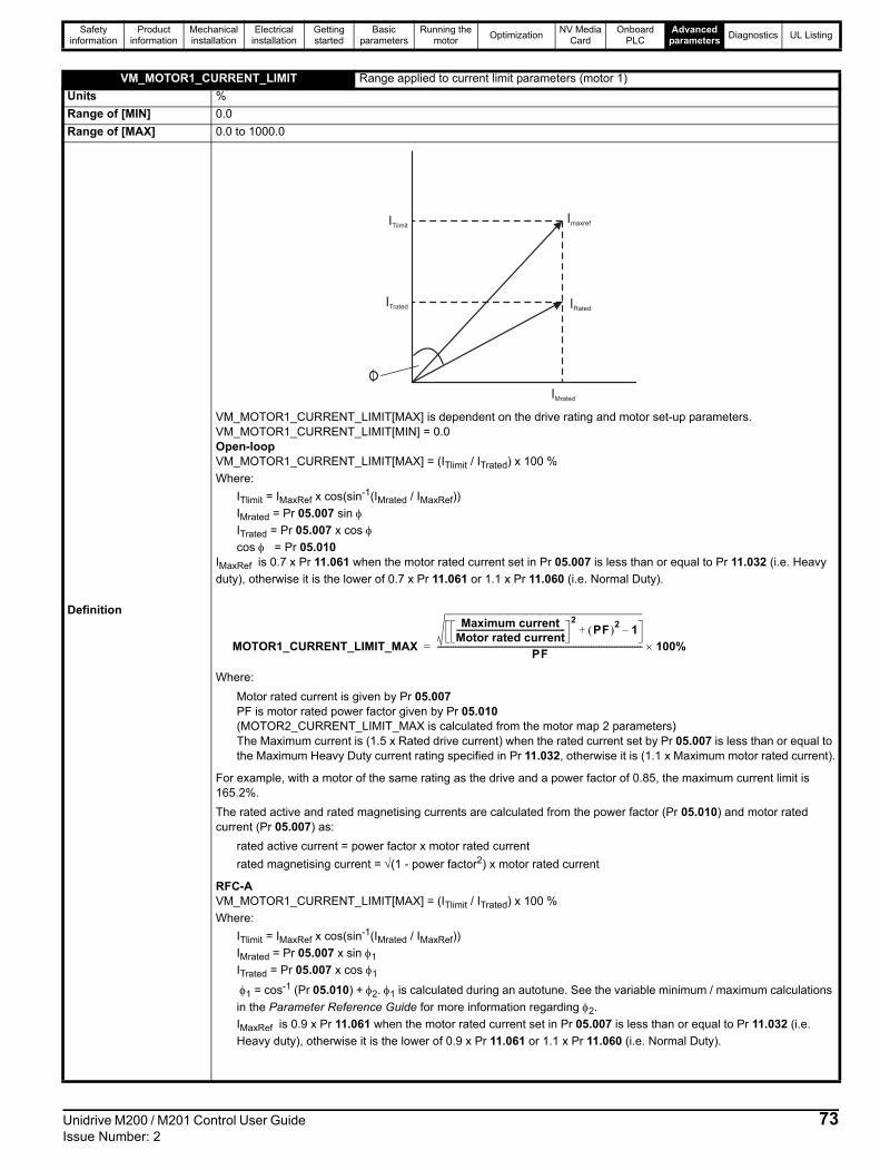
Safety information
Product information
Mechanical installation
Electrical installation
Getting started
Basic parameters
Running the motor
OptimizationNV Media
CardOnboard
PLCAdvanced
parametersDiagnostics UL Listing
VM_MOTOR1_CURRENT_LIMIT Range applied to current limit parameters (motor 1)
Units %
Range of [MIN] 0.0
Range of [MAX] 0.0 to 1000.0
Definition
VM_MOTOR1_CURRENT_LIMIT[MAX] is dependent on the drive rating and motor set-up parameters. VM_MOTOR1_CURRENT_LIMIT[MIN] = 0.0Open-loopVM_MOTOR1_CURRENT_LIMIT[MAX] = (ITlimit / ITrated) x 100 %
Where:
ITlimit = IMaxRef x cos(sin-1(IMrated / IMaxRef))
IMrated = Pr 05.007 sin ITrated = Pr 05.007 x cos cos = Pr 05.010
IMaxRef is 0.7 x Pr 11.061 when the motor rated current set in Pr 05.007 is less than or equal to Pr 11.032 (i.e. Heavy
duty), otherwise it is the lower of 0.7 x Pr 11.061 or 1.1 x Pr 11.060 (i.e. Normal Duty).
Where:
Motor rated current is given by Pr 05.007PF is motor rated power factor given by Pr 05.010(MOTOR2_CURRENT_LIMIT_MAX is calculated from the motor map 2 parameters) The Maximum current is (1.5 x Rated drive current) when the rated current set by Pr 05.007 is less than or equal to the Maximum Heavy Duty current rating specified in Pr 11.032, otherwise it is (1.1 x Maximum motor rated current).
For example, with a motor of the same rating as the drive and a power factor of 0.85, the maximum current limit is 165.2%.
The rated active and rated magnetising currents are calculated from the power factor (Pr 05.010) and motor rated current (Pr 05.007) as:
rated active current = power factor x motor rated current
rated magnetising current = (1 - power factor2) x motor rated current
RFC-AVM_MOTOR1_CURRENT_LIMIT[MAX] = (ITlimit / ITrated) x 100 %
Where:
ITlimit = IMaxRef x cos(sin-1(IMrated / IMaxRef))
IMrated = Pr 05.007 x sin 1
ITrated = Pr 05.007 x cos 1
1 = cos-1 (Pr 05.010) + 2. 1 is calculated during an autotune. See the variable minimum / maximum calculations
in the Parameter Reference Guide for more information regarding 2.
IMaxRef is 0.9 x Pr 11.061 when the motor rated current set in Pr 05.007 is less than or equal to Pr 11.032 (i.e.
Heavy duty), otherwise it is the lower of 0.9 x Pr 11.061 or 1.1 x Pr 11.060 (i.e. Normal Duty).
IMrated
IRated
ImaxrefITlimit
ITrated
MOTOR1_CURRENT_LIMIT_MAX
Maximum currentMotor rated current-------------------------------------------------------
2PF 2 1–+
PF-------------------------------------------------------------------------------------------------------- 100%=
Unidrive M200 / M201 Control User Guide 73Issue Number: 2

Safety information
Product information
Mechanical installation
Electrical installation
Getting started
Basic parameters
Running the motor
OptimizationNV Media
CardOnboard
PLCAdvanced
parametersDiagnostics UL Listing
VM_MOTOR2_CURRENT_LIMIT Range applied to current limit parameters (motor 2)
Units %
Range of [MIN] 0.0
Range of [MAX] 0.0 to 1000.0
Definition
VM_MOTOR2_CURRENT_LIMIT[MAX] is dependent on the drive rating and motor set-up parameters. VM_MOTOR2_CURRENT_LIMIT[MIN] = 0.0Refer to VM_MOTOR1_CURRENT_LIMIT for more information. For VM_MOTOR2_CURRENT_LIMIT[MAX] use Pr 21.007 instead of Pr 05.007 and Pr 21.010 instead of Pr 05.010.
VM_NEGATIVE_REF_CLAMP1 Limits applied to the negative frequency clamp (motor 1)
Units Hz
Range of [MIN] -550.00 to 0.00
Range of [MAX] 0.00 to 550.00
Definition
This variable maximum/minimum defines the range of the negative frequency clamp associated with motor map 1 (Minimum Speed (01.007)). The minimum and maximum are affected by the settings of the Negative Reference Clamp Enable (01.008), Bipolar Reference Enable (01.010) and Maximum Speed (01.006) as shown in the table below.
Negative Reference Clamp Enable (01.008)
Bipolar Reference
Enable (01.010)
VM_NEGATIVE_REF_CLAMP1[MIN]
VM_NEGATIVE_REF_CLAMP1[MAX]
0 0 0.00 Pr 01.006
0 1 0.00 0.00
1 X -VM_POSITIVE_REF_CLAMP[MAX] 0.00
VM_NEGATIVE_REF_CLAMP2 Limits applied to the negative frequency clamp (motor 2)
Units Hz
Range of [MIN] -550.00 to 0.00
Range of [MAX] 0.00 to 550.00
DefinitionThis variable maximum/minimum defines the range of the negative frequency clamp associated with motor map 2 (M2 Minimum Speed (21.002)). It is defined in the same way as VM_NEGATIVE_REF_CLAMP1 except that the M2 Maximum Speed (21.001) is used instead of Maximum Speed (01.006).
VM_POSITIVE_REF_CLAMP Limits applied to the positive frequency reference clamp
Units Hz
Range of [MIN] 0.00
Range of [MAX] 550.00
DefinitionVM_POSITIVE_REF_CLAMP[MAX] defines the range of the positive reference clamp, Maximum Speed (01.006), which in turn limit the references.
VM_POWER Range applied to parameters that either set or display power
Units kW
Range of [MIN] -9999.99 to 0.00
Range of [MAX] 0.00 to 9999.99
Definition
VM_POWER[MAX] is rating dependent and is chosen to allow for the maximum power that can be output by the drive with maximum AC output voltage, at maximum controlled current and unity power factor. VM_POWER[MAX] = 3 x VM_AC_VOLTAGE[MAX] x VM_DRIVE_CURRENT[MAX] / 1000VM_POWER[MIN] = -VM_POWER[MAX]
74 Unidrive M200 / M201 Control User Guide Issue Number: 2

Safety information
Product information
Mechanical installation
Electrical installation
Getting started
Basic parameters
Running the motor
OptimizationNV Media
CardOnboard
PLCAdvanced
parametersDiagnostics UL Listing
VM_RATED_CURRENT Range applied to rated current parameters
Units A
Range of [MIN] 0.00
Range of [MAX] 0.00 to 9999.99
DefinitionVM_RATED_CURRENT [MAX] = Maximum Rated Current (11.060) and is dependent on the drive rating.VM_RATED_CURRENT [MIN] = 0.00
VM_SPEED_FREQ_REF Range applied to the frequency reference parameters
Units Hz
Range of [MIN] -550.00 to 0.00
Range of [MAX] 0.00 to 550.00
Definition
This variable minimum/maximum is applied throughout the frequency and speed reference system so that the references can vary in the range from the minimum to maximum clamps.
VM_SPEED_FREQ_REF[MIN] = -VM_SPEED_FREQ_REF[MAX].
Negative Reference Clamp Enable (01.008)
VM_SPEED_FREQ_REF[MAX] if Select Motor 2 Parameters (11.045) = 0
VM_SPEED_FREQ_REF[MAX] if Select Motor 2 Parameters (11.045) = 1
0 Maximum Speed (01.006) M2 Maximum Speed (21.001)
1Maximum Speed (01.006) or |Minimum Speed (01.007)| whichever the larger
M2 Maximum Speed (21.001) or |M2 Minimum Speed (21.002)| whichever the larger
VM_SPEED_FREQ_REF_UNIPOLAR Unipolar version of VM_SPEED_FREQ_REF
Units Hz
Range of [MIN] 0.00
Range of [MAX] 0.00 to 550.00
DefinitionVM_SPEED_FREQ_REF_UNIPOLAR[MAX] = VM_SPEED_FREQ_REF[MAX].VM_SPEED_FREQ_REF_UNIPOLAR[MIN] = 0.00
VM_SPEED_FREQ_USER_REFS Range applied to analog reference parameters
Units Hz
Range of [MIN] -550.00 to 550.00
Range of [MAX] 0.00 to 550.00
Definition
This variable maximum is applied to Analog Reference 1 (01.036), Analog Reference 2 (01.037) and Keypad Reference (01.017).The maximum applied to these parameters is the same as other frequency reference parameters.VM_SPEED_FREQ_USER_REFS [MAX] = VM_SPEED_FREQ_REF[MAX]However the minimum is dependent on Negative Reference Clamp Enable (01.008) and Bipolar Reference Enable (01.010).
Negative Reference Clamp Enable (01.008)
Bipolar Reference Enable (01.010)
VM_SPEED_FREQ_USER_REFS[MIN]
0 0If Select Motor 2 Parameters (11.045) = 0, Minimum Speed (01.007), otherwise M2 Minimum Speed (21.002)
0 1 -VM_SPEED_FREQ_REF[MAX]
1 0 0.00
1 1 -VM_SPEED_FREQ_REF[MAX]
VM_SUPPLY_LOSS_LEVEL Range applied to the supply loss threshold
Units V
Range of [MIN] 0 to 1150
Range of [MAX] 0 to 1150
DefinitionVM_SUPPLY_LOSS_LEVEL[MAX] = VM_DC_VOLTAGE_SET[MAX]VM_SUPPLY_LOSS_LEVEL[MIN] is drive voltage rating dependent. See Table 11-4
Unidrive M200 / M201 Control User Guide 75Issue Number: 2

Safety information
Product information
Mechanical installation
Electrical installation
Getting started
Basic parameters
Running the motor
OptimizationNV Media
CardOnboard
PLCAdvanced
parametersDiagnostics UL Listing
Table 11-4 Voltage ratings dependant values
VM_TORQUE_CURRENT Range applied to torque and torque producing current parameters
Units %
Range of [MIN] -1000.0 to 0.0
Range of [MAX] 0.0 to 1000.0
Definition
VM_TORQUE_CURRENT[MIN] = -VM_TORQUE_CURRENT[MAX]
Select Motor 2 Parameters (11.045) VM_TORQUE_CURRENT[MAX]
0 VM_MOTOR1_CURRENT_LIMIT[MAX]
1 VM_MOTOR2_CURRENT_LIMIT[MAX]
VM_TORQUE_CURRENT_UNIPOLAR Unipolar version of VM_TORQUE_CURRENT
Units %
Range of [MIN] 0.0
Range of [MAX] 0.0 to 1000.0
Definition
VM_TORQUE_CURRENT_UNIPOLAR[MAX] = VM_TORQUE_CURRENT[MAX]VM_TORQUE_CURRENT_UNIPOLAR[MIN] =0.0User Current Maximum Scaling (04.024) defines the variable maximum/minimums VM_USER_CURRENT which is applied to Percentage Load (04.020) and Torque Reference (04.008). This is useful when routing these parameters to an analog output as it allows the full scale output value to be defined by the user. This maximum is subject to a limit of MOTOR1_CURRENT_LIMIT or MOTOR2_CURRENT_LIMIT depending on which motor map is currently active.The maximum value (VM_TORQUE_CURRENT_UNIPOLAR [MAX]) varies between drive sizes with default parameters loaded. For some drive sizes the default value may be reduced below the value given by the parameter range limiting.
VM_USER_CURRENT Range applied to torque reference and percentage load parameters with one decimal place
Units %
Range of [MIN] -1000.0 to 0.0
Range of [MAX] 0.0 to 1000.0
Definition
VM_USER_CURRENT[MAX] = User Current Maximum Scaling (04.024)VM_USER_CURRENT[MIN] = -VM_USER_CURRENT[MAX] User Current Maximum Scaling (04.024) defines the variable maximum/minimums VM_USER_CURRENT which is applied to Percentage Load (04.020) and Torque Reference (04.008). This is useful when routing these parameters to an analog output as it allows the full scale output value to be defined by the user. This maximum is subject to a limit of MOTOR1_CURRENT_LIMIT or MOTOR2_CURRENT_LIMIT depending on which motor map is currently active.The maximum value (VM_TORQUE_CURRENT_UNIPOLAR [MAX]) varies between drive sizes with default parameters loaded. For some drive sizes the default value may be reduced below the value given by the parameter range limiting.
Variable min/maxVoltage level
100 V 200 V 400 V 575 V 690 V
VM_DC_VOLTAGE_SET(MAX] 400 800 955 1150
VM_DC_VOLTAGE(MAX] Frame 1 to 4
510 870 N/A N/A
VM_DC_VOLTAGE(MAX] Frame 5 to 9
415 830 990 1190
VM_AC_VOLTAGE_SET(MAX] Frame 1 to 4
240 480 N/A N/A
VM_AC_VOLTAGE_SET(MAX] Frame 5 to 9
265 530 635 765
VM_AC_VOLTAGE[MAX] 325 650 780 930
VM_STD_UNDER_VOLTS[MIN] 175 330 435 435
VM_SUPPLY_LOSS_LEVELMIN] 205 410 540 540
76 Unidrive M200 / M201 Control User Guide Issue Number: 2

Safety information
Product information
Mechanical installation
Electrical installation
Getting started
Basic parameters
Running the motor
OptimizationNV Media
CardOnboard
PLCAdvanced
parametersDiagnostics UL Listing
Unidrive M200 / M201 Control User Guide 77Issue Number: 2
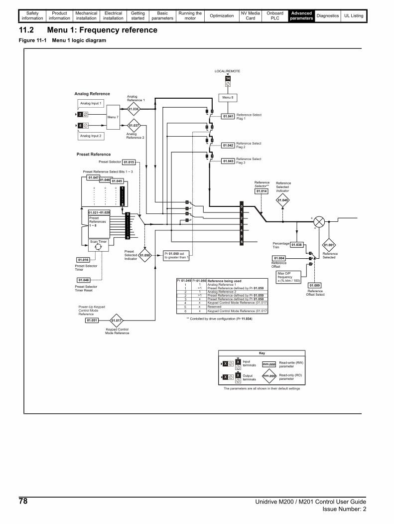
Safety information
Product information
Mechanical installation
Electrical installation
Getting started
Basic parameters
Running the motor
OptimizationNV Media
CardOnboard
PLCAdvanced
parametersDiagnostics UL Listing
11.2 Menu 1: Frequency referenceFigure 11-1 Menu 1 logic diagram
Preset Selector
Preset Selector
Preset SelectorTimer Reset
Timer
Keypad ControlMode Reference
AnalogReference 1
AnalogReference 2
Preset Reference Select Bits 1 ~ 3
Menu 7
01.037
01.041
01.016
01.015
01.017
LOCAL/REMOTE
Menu 8
Reference**Selector
Reference
Selected
Indicator01.014
** Contolled by drive configuration (Pr )11.034
PercentageTrim
Max O/Pfrequencyx (% trim / 100)
Analog Input 1
Analog Reference
Preset Reference
mm.ppp
mm.ppp
Key
Read-write (RW)parameter
Read-only (RO)parameter
Inputterminals
Outputterminals
The parameters are all shown in their default settings
01.051
Power-Up KeypadControl ModeReference
1.20
PresetSelectedIndicator
PresetReferences
~01.028
Scan Timer
01.043
01.042
Pr setto greater than 1
01.05001.050
11223
1>11
>1x
Reference being used
01.050
01.050
Analog Reference 1Preset Reference defined by PrAnalog Reference 2Preset Reference defined by Pr
4 x Keypad Control Mode Reference (01.017)
5 x Reserved
6 x Keypad Control Mode Reference (01.017)
Preset Reference defined by Pr 01.050
Reference SelectFlag 1
Reference SelectFlag 2
Reference SelectFlag 3
01.036
01.021
01.049
Pr 01.049 Pr 01.050
Analog Input 2
ReferenceSelected
ReferenceOffset
ReferenceOffset Select
01.004
01.038 01.001
+
+1 ~ 8
01.04701.046 01.045
8
1
0
9
01.048
78 Unidrive M200 / M201 Control User Guide Issue Number: 2

Safety information
Product information
Mechanical installation
Electrical installation
Getting started
Basic parameters
Running the motor
OptimizationNV Media
CardOnboard
PLCAdvanced
parametersDiagnostics UL Listing
Bipolarreference
enable
Jog select
Menu 6Sequencer
01.010
01.013
MaximumSpeed
MinimumSpeed
NegativeReferenceClampEnable
Reverseselect
01.006
01.007
Sequencer (Menu 6)
Menu 8
RUN FORWARD RUN REVERSE
Jogreference
01.005
x(-1)
01.008 [01.006]
[01.007]
[01.007]
[01.006]
[01.006]
[01.006]
[01.006]
[01.007]
01.071
01.070
Alternativereference
Clampedreference
01.072
Alternativereferenceenable
Pre-skipFilter Reference
Pre-rampreference
Reference InRejection Zone
ReferenceOn
01.002 01.003
01.011
Menu 2
01.035
SkipReference
1
SkipReference
2
SkipReference
3
SkipReference
Band1
SkipReference
Band2
SkipReference
Band3
01.029
01.030
01.031
01.032
01.033
01.034
01.057
ForceReferenceDirection
01.069
Referencein rpm
Unidrive M200 / M201 Control User Guide 79Issue Number: 2

Safety information
Product information
Mechanical installation
Electrical installation
Getting started
Basic parameters
Running the motor
OptimizationNV Media
CardOnboard
PLCAdvanced
parametersDiagnostics UL Listing
* Keypad mode for the Unidrive M201.
ParameterRange () Default ()
TypeOL RFC-A OL RFC-A
01.001 Reference Selected 0.00 to Pr 01.006 Hz RO Num ND NC PT
01.002 Pre-skip Filter Reference 0.00 to Pr 01.006 Hz RO Num ND NC PT
01.003 Pre-ramp Reference 0.00 to Pr 01.006 Hz RO Num ND NC PT
01.004 Reference Offset 0.00 to Pr 01.006 Hz 0.00 Hz RW Num US
01.005 Jog Reference 0.00 to 300.00 Hz 1.50 Hz RW Num US
01.006 Maximum Speed 0.00 to 550.00 Hz50Hz: 50.00 Hz60Hz: 60.00 Hz
RW Num US
01.007 Minimum Speed 0.00 to Pr 01.006 Hz 0.00 Hz RW Num US
01.008 Negative Reference Clamp Enable Off (0) or On (1) Off (0) RW Bit US
01.009 Reference Offset Select 0 to 2 0 RW Num US
01.010 Bipolar Reference Enable Off (0) or On (1) Off (0) RW Bit US
01.011 Reference On Off (0) or On (1) RO Bit ND NC PT
01.012 Reverse Select Off (0) or On (1) RO Bit ND NC PT
01.013 Jog Select Off (0) or On (1) RO Bit ND NC PT
01.014 Reference SelectorA1.A2 (0), A1.Pr (1), A2.Pr (2), PrESEt (3),
PAd (4), rES (5), PAd.rEF (6)A1.A2 (0)* RW Txt US
01.015 Preset Selector 0 to 9 0 RW Num US
01.016 Preset Selector Timer 0 to 400.0 s 10.0s RW Num US
01.017 Keypad Control Mode Reference VM_SPEED_FREQ_USER_REFS Hz 0.00 Hz RO Num NC PT PS
01.021 Preset Reference 1 0.00 to Pr 01.006 Hz 0.00 Hz RW Num US
01.022 Preset Reference 2 0.00 to Pr 01.006 Hz 0.00 Hz RW Num US
01.023 Preset Reference 3 0.00 to Pr 01.006 Hz 0.00 Hz RW Num US
01.024 Preset Reference 4 0.00 to Pr 01.006 Hz 0.00 Hz RW Num US
01.025 Preset Reference 5 0.00 to Pr 01.006 Hz 0.00 Hz RW Num US
01.026 Preset Reference 6 0.00 to Pr 01.006 Hz 0.00 Hz RW Num US
01.027 Preset Reference 7 0.00 to Pr 01.006 Hz 0.00 Hz RW Num US
01.028 Preset Reference 8 0.00 to Pr 01.006 Hz 0.00 Hz RW Num US
01.029 Skip Reference 1 0.00 to 550.00 Hz 0.00 Hz RW Num US
01.030 Skip Reference Band 1 0.00 to 25.00 Hz 0.50 Hz RW Num US
01.031 Skip Reference 2 0.00 to 550.00 Hz 0.00 Hz RW Num US
01.032 Skip Reference Band 2 0.00 to 25.00 Hz 0.50 Hz RW Num US
01.033 Skip Reference 3 0.00 to 550.00 Hz 0.00 Hz RW Num US
01.034 Skip Reference Band 3 0.00 to 25.00 Hz 0.50 Hz RW Num US
01.035 Reference In Rejection Zone Off (0) or On (1) RO Bit ND NC PT
01.036 Analog Reference 1 VM_SPEED_FREQ_USER_REFS Hz 0.00 Hz RO Num NC
01.037 Analog Reference 2 VM_SPEED_FREQ_USER_REFS Hz 0.00 Hz RO Num NC
01.038 Percentage Trim ± 100.00 % 0.00 % RW Num NC
01.041 Reference Select Flag 1 Off (0) or On (1) Off (0) RW Bit NC
01.042 Reference Select Flag 2 Off (0) or On (1) Off (0) RW Bit NC
01.043 Reference Select Flag 3 Off (0) or On (1) Off (0) RW Bit NC
01.045 Preset Select Flag 1 Off (0) or On (1) Off (0) RW Bit NC
01.046 Preset Select Flag 2 Off (0) or On (1) Off (0) RW Bit NC
01.047 Preset Select Flag 3 Off (0) or On (1) Off (0) RW Bit NC
01.048 Preset Selector Timer Reset Off (0) or On (1) Off (0) RW Bit NC
01.049 Reference Selected Indicator 1 to 6 RO Num ND NC PT
01.050 Preset Selected Indicator 1 to 8 RO Num ND NC PT
01.051Power-up Keypad Control Mode Refer-ence
rESEt (0), LASt (1), PrESEt (2) rESEt (0) RW Txt US
01.057 Force Reference Direction NonE (0), For (1), rEv (2) NonE (0) RW Txt
01.069 Reference in rpm ± 33000.0 rpm RO Num ND NC PT
01.070 Clamped Reference 0.00 to Pr 01.006 Hz RO Num ND NC PT
01.071 Alternative Reference 0.00 to Pr 01.006 Hz 0.00 Hz RW Num NC PT
01.072 Alternative Reference Enable Off (0) or On (1) RO Bit ND NC PT
RW Read / Write RO Read only Num Number parameter Bit Bit parameter Txt Text string Bin Binary parameter FI Filtered
ND No default value NC Not copied PT Protected parameter RA Rating dependent US User save PS Power-down save DE Destination
80 Unidrive M200 / M201 Control User Guide Issue Number: 2

Safety information
Product information
Mechanical installation
Electrical installation
Getting started
Basic parameters
Running the motor
OptimizationNV Media
CardOnboard
PLCAdvanced
parametersDiagnostics UL Listing
Unidrive M200 / M201 Control User Guide 81Issue Number: 2

Safety information
Product information
Mechanical installation
Electrical installation
Getting started
Basic parameters
Running the motor
OptimizationNV Media
CardOnboard
PLCAdvanced
parametersDiagnostics UL Listing
11.3 Menu 2: RampsFigure 11-2 Menu 2 logic diagram
0 0 0
0 0 1
0 1 0
0 1 1
1 0 0
1 0 1
1 1 0
1 1 1
Acceleration Rate Select Bits
02.011 Acceleration Rate 1
02.012 Acceleration Rate 2
02.013 Acceleration Rate 3
02.014 Acceleration Rate 4
02.015 Acceleration Rate 5
02.016 Acceleration Rate 6
02.017 Acceleration Rate 7
02.018 Acceleration Rate 8
Acceleration rates 1 ~ 8
01.050Preset SelectedIndicator
02.019Jog Acceleration
Rate
01.013Jog Select
01.003Pre-RampReference
02.003 Ramp Hold
02.004 Ramp Mode Select
N
t
N
t
Acceleration
ReverseAccel. Rate
ForwardAccel. Rate
Ramp Control
02.010
AccelerationRate Selector
02.034 02.033 2.3202.032
02.030AccelerationRate Selected
02.008
02.009
Standard Ramp Voltage
Deceleration FailDetection Disable
02.039 Ramp Rate Units
mm.ppp
mm.ppp
Key
Read-write (RW)parameter
Read-only (RO)parameter
Inputterminals
Outputterminals
The parameters are all shown in their default settings
02.042Maximum Rate Of ChangeOf Acceleration 1
02.043Maximum Rate Of ChangeOf Acceleration 2
02.011 Acceleration Rate 1
02.012 Acceleration Rate 2
02.013 Acceleration Rate 3
02.014 Acceleration Rate 4
02.015 Acceleration Rate 5
02.016 Acceleration Rate 6
02.017 Acceleration Rate 7
02.018 Acceleration Rate 8
02.011 Acceleration Rate 1
02.012 Acceleration Rate 2
02.013 Acceleration Rate 3
02.014 Acceleration Rate 4
02.015 Acceleration Rate 5
02.016 Acceleration Rate 6
02.017 Acceleration Rate 7
02.018 Acceleration Rate 8
3
4
1
2
7
8
5
6
82 Unidrive M200 / M201 Control User Guide Issue Number: 2

Safety information
Product information
Mechanical installation
Electrical installation
Getting started
Basic parameters
Running the motor
OptimizationNV Media
CardOnboard
PLCAdvanced
parametersDiagnostics UL Listing
02.006 S-Ramp Enable
02.007Max Rate OfChange OfAcceleration
02.040 S-Ramp Percentage
Ramp Control
N
t
N
t
Deceleration
ForwardDecel. rate
ReverseDecel. rate
+
_
02.001
Post-RampReference
02.002Ramp E(RFC-A mode only)
nable
Current controlMenu 4(Open-loop only)
Deceleration Rates 1 ~ 8
02.021 Deceleration Rate 1
02.022 Deceleration Rate 2
02.023 Deceleration Rate 3
02.024 Deceleration Rate 4
02.025 Deceleration Rate 5
02.026 Deceleration Rate 6
02.027 Deceleration Rate 7
02.028 Deceleration Rate 8
01.050
PresetSelectedIndicator
02.029Jog DecelerationRate
01.013 Jog Select
02.038
InertiaCompensation
Torque
d/dt
02.020
DecelerationRate Selector
Deceleration Rate Select Bits
02.037 02.036 02.035
Ramps always enabledin Open-loop
02.031DecelerationRate Selected
03.018
05.032
Motor And LoadInertia
Torque Per Amp
02.041 S-Ramp Set-up Mode
02.044Maximum Rate OfChange Of Acceleration 3
02.045Maximum Rate OfChange Of Acceleration 4
02.021 Deceleration Rate 1
02.022 Deceleration Rate 2
02.023 Deceleration Rate 3
02.024 Deceleration Rate 4
02.025 Deceleration Rate 5
02.026 Deceleration Rate 6
02.027 Deceleration Rate 7
02.028 Deceleration Rate 8
02.021 Deceleration Rate 1
02.022 Deceleration Rate 2
02.023 Deceleration Rate 3
02.024 Deceleration Rate 4
02.025 Deceleration Rate 5
02.026 Deceleration Rate 6
02.027 Deceleration Rate 7
02.028 Deceleration Rate 8
3
4
1
2
7
8
5
6
Unidrive M200 / M201 Control User Guide 83Issue Number: 2

Safety information
Product information
Mechanical installation
Electrical installation
Getting started
Basic parameters
Running the motor
OptimizationNV Media
CardOnboard
PLCAdvanced
parametersDiagnostics UL Listing
ParameterRange () Default ()
TypeOL RFC-A OL RFC-A
02.001 Post Ramp Reference 0.00 to Pr 01.006 Hz RO Num ND NC PT
02.002 Ramp Enable Off (0) or On (1) On (1) RW Bit US
02.003 Ramp Hold Off (0) or On (1) Off (0) RW Bit US
02.004 Ramp Mode Select FASt (0), Std (1), Std.bSt (2), FSt.bSt (3) Std (1) RW Txt US
02.005 Disable Ramp Output Off (0) or On (1) Off (0) RW Bit US
02.006 S Ramp Enable Off (0) or On (1) Off (0) RW Bit US
02.007 Max Rate Of Change Of Acceleration 0.0 to 300.0 s²/100Hz 3.1 s²/100 Hz RW Num US
02.008 Standard Ramp Voltage 0 to 1150 V
110 V drive: 375 V200 V drive: 375 V
400 V drive 50 Hz: 750 V400 V drive 60 Hz: 775 V
575 V drive: 895 V690 V drive: 1075 V
RW Num RA US
02.009 Deceleration Fail Detection Disable Off (0) or On (1) Off (0) RW Bit US
02.010 Acceleration Rate Selector 0 to 9 0 RW Num US
02.011 Acceleration Rate 1
0.0 to 32000.0 s/100 Hz 5.0 s/100 Hz
RW Num US
02.012 Acceleration Rate 2 RW Num US
02.013 Acceleration Rate 3 RW Num US
02.014 Acceleration Rate 4 RW Num US
02.015 Acceleration Rate 5 RW Num US
02.016 Acceleration Rate 6 RW Num US
02.017 Acceleration Rate 7 RW Num US
02.018 Acceleration Rate 8 RW Num US
02.019 Jog Acceleration Rate 0.0 to 32000.0 s/100 Hz 0.2 s/100 Hz RW Num US
02.020 Deceleration Rate Selector 0 to 9 0 RW Num US
02.021 Deceleration Rate 1
0.0 to 32000.0 s/100 Hz 10.0 s/100 Hz
RW Num US
02.022 Deceleration Rate 2 RW Num US
02.023 Deceleration Rate 3 RW Num US
02.024 Deceleration Rate 4 RW Num US
02.025 Deceleration Rate 5 RW Num US
02.026 Deceleration Rate 6 RW Num US
02.027 Deceleration Rate 7 RW Num US
02.028 Deceleration Rate 8 RW Num US
02.029 Jog Deceleration Rate 0.0 to 32000.0 s/100 Hz 0.2 s/100 Hz RW Num US
02.030 Acceleration Rate Selected 0 to 8 RO Num ND NC PT
02.031 Deceleration Rate Selected 0 to 8 RO Num ND NC PT
02.032 Acceleration Rate Select Bit 0 Off (0) or On (1) Off (0) RW Bit NC
02.033 Acceleration Rate Select Bit 1 Off (0) or On (1) Off (0) RW Bit NC
02.034 Acceleration Rate Select Bit 2 Off (0) or On (1) Off (0) RW Bit NC
02.035 Deceleration Rate Select Bit 0 Off (0) or On (1) Off (0) RW Bit NC
02.036 Deceleration Rate Select Bit 1 Off (0) or On (1) Off (0) RW Bit NC
02.037 Deceleration Rate Select Bit 2 Off (0) or On (1) Off (0) RW Bit NC
02.038 Inertia Compensation Torque ± 1000.0 % RO Num ND NC PT
02.039 Ramp Rate Units0 (s/100 Hz), 1 (s/Maximum Frequency),
2 (s/1000 Hz)0 (s/100 Hz) RW Num US
02.040 S Ramp Percentage 0.0 to 50.0 % 0.0 % RW Num US
02.041 S Ramp Set-up Mode 0 to 2 0 RW Num US
02.042Maximum Rate Of Change Of Acceleration 1
0.0 to 300.0 s²/100 Hz 0.0 s²/100 Hz RW Num US
02.043Maximum Rate Of Change OfAcceleration 2
0.0 to 300.0 s²/100 Hz 0.0 s²/100 Hz RW Num US
02.044Maximum Rate Of Change OfAcceleration 3
0.0 to 300.0 s²/100 Hz 0.0 s²/100 Hz RW Num US
02.045Maximum Rate Of Change OfAcceleration 4
0.0 to 300.0 s²/100 Hz 0.0 s²/100 Hz RW Num US
RW Read / Write RO Read only Num Number parameter Bit Bit parameter Txt Text string Bin Binary parameter FI Filtered
ND No default value NC Not copied PT Protected parameter RA Rating dependent US User save PS Power-down save DE Destination
84 Unidrive M200 / M201 Control User Guide Issue Number: 2

Safety information
Product information
Mechanical installation
Electrical installation
Getting started
Basic parameters
Running the motor
OptimizationNV Media
CardOnboard
PLCAdvanced
parametersDiagnostics UL Listing
Figure 11-3 Menu 3 Open-loop logic diagram
11.4 Menu 3: Frequency control
+
_
03.00510.003
ZeroFrequency
Zero FrequencyThreshold
+
_
01.007Running At Or BelowMinimum Frequency
MinimumSpeed
+
_
03.00610.005
Below Set-FrequencyAt FrequencyLower Limit
+
_10.007
Above Set-FrequencyAt FrequencyUpper Limit
10.006
At Frequency
10.004
0
1
01.010
Bipolar ReferenceEnable
NOR
+0.5Hz
+
_Over SpeedTrip
1
0+20%01.006
03.008
MaximumSpeed
OverFrequencyThreshold
03.008>0
mm.ppp
mm.ppp
Key
Read-write (RW)parameter
Read-only (RO)parameter
Inputterminals
Outputterminals
The parameters are all shown in their default settings
02.001
01.011
Post RampReference
Referenceon
Hard FrequencyReference
Hard FrrequencyReferenceSelect
03.023
03.022
05.001
OutputFrequency
+
+
+
+
Slipcompensation
Menu 5
Menu 2
01
01
03.007
01.003
Pre RampReference
03.009
AbsoluteAt-SpeedSelect
+
_
0
1
03.001
01.006
01.007
01.008
Maximum Speed
Minimum Speed
Negative ReferenceClamp Enable
03.072
Motor SpeedPercent
Final DemandReference
Unidrive M200 / M201 Control User Guide 85Issue Number: 2

Safety information
Product information
Mechanical installation
Electrical installation
Getting started
Basic parameters
Running the motor
OptimizationNV Media
CardOnboard
PLCAdvanced
parametersDiagnostics UL Listing
Figure 11-4 Menu 3 RFC-A logic diagram
02.001
Post-RampReference
+
+
03.023
01.011
Hard FrequencyReferenceSelect
ReferenceOn
Final DemandReference
03.022Hard FrequencyReference
02.005
Disable RampOutput
VM_SPEED_FREQ_REF[MIN]
VM_SPEED_FREQ_REF[MAX]
03.001
03.079
SensorlessMode Filter
03.080 d/dt
SensorlessPosition
01.006
01.007
01.008
Maximum Speed
Minimum Speed
Negative ReferenceClamp Enable
03.072
Motor SpeedPercent
86 Unidrive M200 / M201 Control User Guide Issue Number: 2
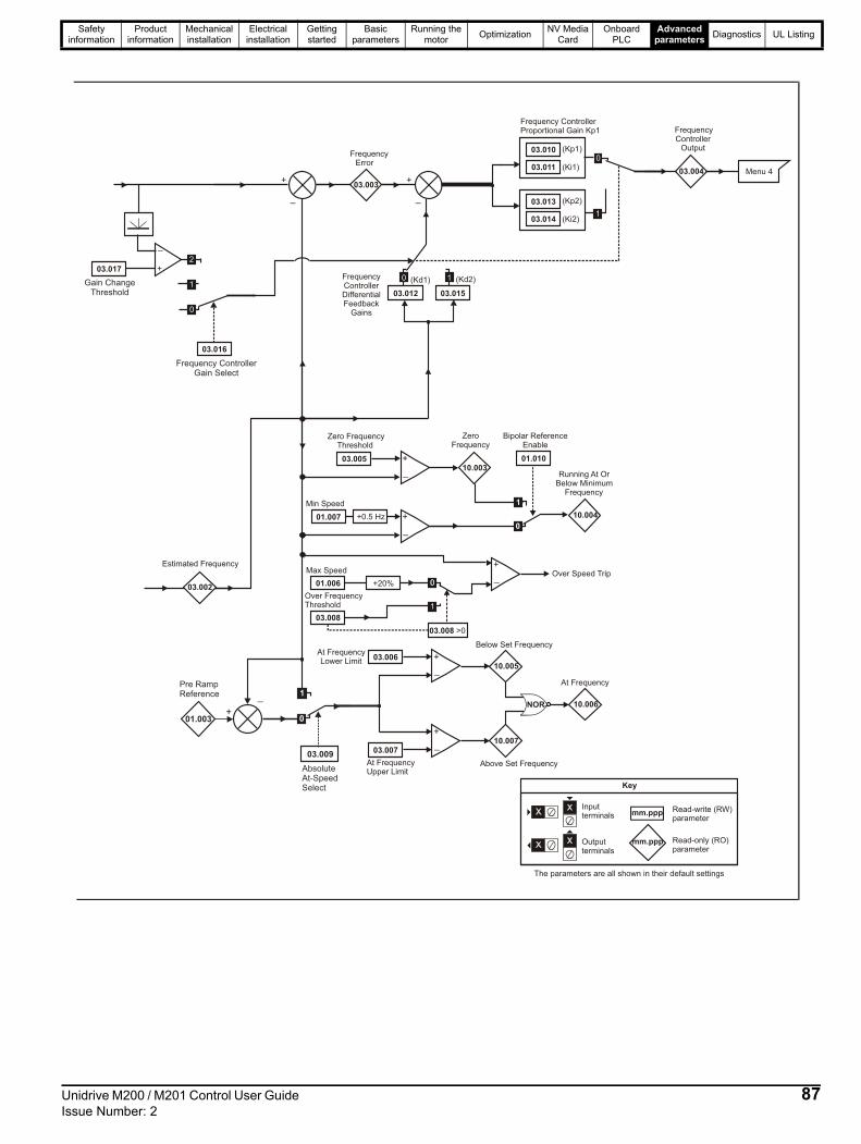
Safety information
Product information
Mechanical installation
Electrical installation
Getting started
Basic parameters
Running the motor
OptimizationNV Media
CardOnboard
PLCAdvanced
parametersDiagnostics UL Listing
+
_
03.003
FrequencyError
Frequency ControllerProportional Gain Kp1
+
_Over Speed Trip
01.006
Max Speed
+
_
03.00610.005
Below Set FrequencyAt FrequencyLower Limit
+
_03.007
10.007
At FrequencyUpper Limit
10.006
At Frequency
NOR
+
_
03.00510.003
ZeroFrequency
Zero FrequencyThreshold
+
_
01.007 10.004
Running At OrBelow Minimum
Frequency
Min Speed
0
1
01.010
Bipolar ReferenceEnable
+0.5 Hz
+20%
FrequencyControllerDifferentialFeedback
Gains
0
1
03.008
Over FrequencyThreshold
03.008 >0
03.010
03.011 (Ki1)
(Kp1)
03.013
03.014 (Ki2)
(Kp2)
03.004
FrequencyController
Output
Menu 4
Estimated Frequency
03.002
+
_
(Kd1) (Kd2)
03.01503.012
10
Above Set Frequency
mm.ppp
mm.ppp
Key
Read-write (RW)parameter
Read-only (RO)parameter
Inputterminals
Outputterminals
XX
XX
The parameters are all shown in their default settings
0
1
+
_
03.017
0
1
2
03.016
Frequency ControllerGain Select
Gain ChangeThreshold
01.003
Pre RampReference
03.009
AbsoluteAt-SpeedSelect
+
_
0
1
Unidrive M200 / M201 Control User Guide 87Issue Number: 2

Safety information
Product information
Mechanical installation
Electrical installation
Getting started
Basic parameters
Running the motor
OptimizationNV Media
CardOnboard
PLCAdvanced
parametersDiagnostics UL Listing
Figure 11-5 Menu 3 logic diagram
mm.ppp
mm.ppp
Key
Read-write (RW)parameter
Read-only (RO)parameter
Inputterminals
Outputterminals
The parameters are all shown in their default settings
T10 DigitalI/O 1
03.037
??.???
??.???
At ZeroFrequency
10.003
Any validparameter
Maximum OutputFrequency
T10 Digital I/O 01Output Select
Frequency Output orPWM Output Scaling
T10 DO1ControlT10 DI/O 01 Source
/ Destination B
T10 Digital IO1Source
/ Destination A
08.091
08.021
≥1
03.038
08.031
2 or 3
0 to 1
10
T14 DigitalInput 5 Select
FrequencyReference
FrequencyReferenceScaling
MaximumReferenceFrequency
Position CounterReset
PositionScaling
Position
T14 Digital Input 5
08.035
14
0 to 3
4 03.043
03.032
03.045
32 Bit PositionCounter
03.03503.036
03.029
03.044
T14 DI5 control
08.085
??.???
??.???
01.041
Any unprotectedbit parameter
ReferenceSelect Flag 1
≥1
T14 DI 05Destination B
T14 Digital input5 destination A
08.025
08.125
08.121
03.047 Two PointMinimumFrequency
03.048 DriveReferenceat MinimumFrequency
03.049 Two PointMaximumFrequency
03.050DriveReferenceat MaximumFrequency
88 Unidrive M200 / M201 Control User Guide Issue Number: 2

Safety information
Product information
Mechanical installation
Electrical installation
Getting started
Basic parameters
Running the motor
OptimizationNV Media
CardOnboard
PLCAdvanced
parametersDiagnostics UL Listing
ParameterRange () Default ()
TypeOL RFC-A OL RFC-A
03.001 Final Demand Reference-Pr 01.006 to Pr 01.006 or Pr 01.007 to
Pr 01.006 HzRO Num ND NC PT FI
03.002 Estimated Frequency-Pr 01.006 to Pr 01.006
or Pr 01.007 to Pr 01.006 Hz
RO Num ND NC PT FI
03.003 Frequency Error-Pr 01.006 to Pr 01.006
or Pr 01.007 to Pr 01.006 Hz
RO Num ND NC PT FI
03.004 Frequency Controller OutputVM_TORQUE_CURRENT %
RO Num ND NC PT FI
03.005 Zero Frequency Threshold 0.00 to 20.00 Hz 2.00 Hz RW Num US
03.006 At Frequency Lower Limit 0.00 to 550.00 Hz 1.00 Hz RW Num US
03.007 At Frequency Upper Limit 0.00 to 550.00 Hz 1.00 Hz RW Num US
03.008 Over Frequency Threshold 0.00 to 550.00 Hz 0.00 Hz RW Num US
03.009 Absolute At Frequency Select Off (0) or On (1) Off (0) RW Bit US
03.010 Frequency Controller Proportional Gain Kp1 0.000 to 200.000 s/rad 0.100 s/rad RW Num US
03.011 Frequency Controller Integral Gain Ki1 0.00 to 655.35 s²/rad 0.10 s²/rad RW Num US
03.012Frequency Controller Differential FeedbackGain Kd1
0.00000 to 0.65535 1/rad0.00000 1/
radRW Num US
03.013 Frequency Controller Proportional Gain Kp2 0.000 to 200.000 s/rad 0.100 s/rad RW Num US
03.014 Frequency Controller Integral GainKi2 0.00 to 655.35 s²/rad 0.10 s²/rad RW Num US
03.015Frequency Controller Differential FeedbackGain Kd2
0.00000 to 0.65535 1/rad0.00000 1/
radRW Num US
03.016 Frequency Controller Gain Select 0 to 2 0 RW Num US
03.017 Gain Change Threshold 0.00 to 550.00 Hz 0.00 Hz RW Num FI
03.018 Motor and Load Inertia 0.00 to 1000.00 kgm² 0.00 kgm² RW Num US
03.022 Hard Frequency Reference 0.00 to Pr 01.006 Hz 0.00 Hz RW Num US
03.023 Hard Frequency Reference Select Off (0) or On (1) Off (0) RW Bit US
03.029 Position (T14) 0 to 65535 RO Num ND NC PT FI
03.032 Position Counter Reset (T14) Off (0) or On (1) Off (0) RW Bit NC
03.035 Position Scaling Numerator (T14) 0.000 to 1.000 1.000 RW Num US
03.036 Position Scaling Denominator (T14) 0.000 to 100.000 1.000 RW Num US
03.037Frequency Output or PWM OutputScaling (T10)
0.000 to 4.000 1.000 RW Num US
03.038 Maximum Output Frequency (T10) 1 (0), 2 (1), 5 (2), 10 (3) kHz 5 (2) kHz RW Txt US
03.042 Frequency Input High Precision Off (0) or On (1) Off (0) RW Bit US
03.043 Maximum Reference Frequency (T14) 0.00 to 100.00 kHz 10.00 kHz RW Num US
03.044 Frequency Reference Scaling (T14) 0.000 to 4.000 1.000 RW Num US
03.045 Frequency Reference (T14) 0.00 to 100.00 % RO Num ND NC PT FI
03.047 Two Point Minimum Frequency (T14) 0.00 to 100.00 % 0.00 % RW Num US
03.048 Drive Reference at Minimum Frequency (T14) 0.00 to 100.00 % 0.00 % RW Num US
03.049 Two Point Maximum Frequency (T14) 0.00 to 100.00 % 100.00 % RW Num US
03.050Drive Reference at MaximumFrequency (T14)
0.00 to 100.00 % 100.00 % RW Num US
03.072 Motor Speed Percent ± 150.0 % RO ND NC PT FI
03.079 Sensorless Mode Filter4 (0), 5 (1), 6 (2), 8 (3),
12 (4), 20 (5) ms4 (0) ms RW Txt US
03.080 Sensorless Position 0 to 65535 RO Num ND NC PT
RW Read / Write RO Read only Num Number parameter Bit Bit parameter Txt Text string Bin Binary parameter FI Filtered
ND No default value NC Not copied PT Protected parameter RA Rating dependent US User save PS Power-down save DE Destination
Unidrive M200 / M201 Control User Guide 89Issue Number: 2

Safety information
Product information
Mechanical installation
Electrical installation
Getting started
Basic parameters
Running the motor
OptimizationNV Media
CardOnboard
PLCAdvanced
parametersDiagnostics UL Listing
11.5 Menu 4: Torque and current controlFigure 11-6 Menu 4 Open loop logic diagram
04.008
10.00910.008
04.015 04.01604.018
11.032
05.007
04.005 Motoring
Regenerating
Current limits
Symmetrical
MaximumHeavy Duty
Rating
MotorRated
Current
FinalCurrent Limit
TorqueReference
Motor ThermalTime Constant 1
ThermalProtection
Mode
RatedLoad Reached
Current LimitActive
CurrentMagnitude
MagnetisingCurrent
04.020 - PercentageLoad
04.00204.020
10.01704.019
MotorProtection
Accumulator
Motor OverloadAlarm
10.039
Braking ResistorThermal
Accumulator
04.004
FinalCurrent
Reference
Torque tocurrent
conversion
05.006
OutputFrequency
FinalTorque
Reference
05.001
MotorRated
Frequency
05.001Motor map2.01
Post RampReference
OutputFrequency
02.001
Torque ModeSelector
04.011
04.013
04.014
P Gain
I Gain
Current Controller
10.009
CurrentLimit
Active
2.01
Pre RampReference
01.003
Menu 2 rampcontroller
+
_
04.025
Low FrequencyThermal
Protection Mode
Overload detection
+
+
04.001
04.017
TorqueProducing
Current
mm.ppp
mm.ppp
Key
Read-write (RW)parameter
Read-only (RO)parameter
Inputterminals
Outputterminals
The parameters are all shown in their default settings
04.003
04.026 - PercentageTorque
04.024 - User CurrentMaximum
Scaling
04.036
MotorProtection
AccumulatorPower-up Value
90 Unidrive M200 / M201 Control User Guide Issue Number: 2

Safety information
Product information
Mechanical installation
Electrical installation
Getting started
Basic parameters
Running the motor
OptimizationNV Media
CardOnboard
PLCAdvanced
parametersDiagnostics UL Listing
Figure 11-7 Menu 4 RFC-A logic diagram
04.004
FinalCurrent
Reference
+
_
03.004+
03.001
03.002
04.008
10.00910.008
04.015 04.016
04.013
04.014
CurrentControllerP Gain
CurrentControllerI Gain
Current Controller
04.018
11.032
05.007
04.005 Motoring
Regenerating
Current limits
Symmetrical
MaximumHeavy Duty
Rating
MotorRated
Current
Estimatedfrequency
FinalDemand
Reference
_
FinalCurrent Limit
03.005Zero
FrequencyThreshold
FrequencyController
Output
TorqueReference
FrequencyOver-Ride
Level
Coiler/UncoilerFrequencyOver-Ride
Level
Motor ThermalTime Constant 1
ThermalProtection
Mode
Rated LoadReached
Current LimitActive
05.007 05.010
MotorRatedPowerFactor
MotorRated
Current
Torque ProducingCurrent(Amp)
CurrentMagnitude
MagnetisingCurrent
04.002
04.017
04.001
10.01704.019
MotorProtection
Accumulator
Motor OverloadAlarm
10.039
Braking ResistorThermal
Accumulator
Torque ModeSelector
04.011
+
+
04.003
FinalTorque
Reference
04.024
04.025
Low FrequencyThermal
Protection Mode
Overload detection
User CurrentMaximum Scaling
01.003Pre-RampReference
+
04.022
02.038
InertiaCompensation
Enable
+
InertiaCompensation
Torque
mm.ppp
mm.ppp
Key
Read-write (RW)parameter
Read-only (RO)parameter
Inputterminals
Outputterminals
The parameters are all shown in their default settings
04.020 - PercentageLoad
04.036
MotorProtection
AccumulatorPower-up Value
Unidrive M200 / M201 Control User Guide 91Issue Number: 2

Safety information
Product information
Mechanical installation
Electrical installation
Getting started
Basic parameters
Running the motor
OptimizationNV Media
CardOnboard
PLCAdvanced
parametersDiagnostics UL Listing
* For size 9 the default is 141.9 %
** For size 9 the default is 150.0 %
ParameterRange () Default ()
TypeOL RFC-A OL RFC-A
04.001 Current Magnitude 0 to Drive Maximum Current A RO Num ND NC PT FI
04.002 Torque Producing Current ± Drive Maximum Current A RO Num ND NC PT FI
04.003 Final Torque Reference VM_TORQUE_CURRENT % RO Num ND NC PT FI
04.004 Final Current Reference VM_TORQUE_CURRENT % RO Num ND NC PT FI
04.005 Motoring Current Limit 0.0 to VM_MOTOR1_CURRENT_LIMIT % 165.0 %* 175.0 %** RW Num RA US
04.006 Regenerating Current Limit 0.0 to VM_MOTOR1_CURRENT_LIMIT % 165.0 %* 175.0 %** RW Num RA US
04.007 Symmetrical Current Limit 0.0 to VM_MOTOR1_CURRENT_LIMIT % 165.0 %* 175.0 %** RW Num RA US
04.008 Torque Reference VM_USER_CURRENT % 0.0 % RW Num US
04.011 Torque Mode Selector 0 to 1 0 to 5 0 RW Num US
04.013 Current Controller Kp Gain 0.00 to 4000.00 20.00 RW Num US
04.014 Current Controller Ki Gain 0.000 to 600.000 40.000 RW Num US
04.015 Motor Thermal Time Constant 1 1 to 3000 s 179 s RW Num US
04.016 Thermal Protection Mode 0 (0) to 3 (3) 0 (0) RW Bin US
04.017 Magnetising Current 0 to Drive Maximum Current A RO Num ND NC PT FI
04.018 Final Current Limit VM_TORQUE_CURRENT % RO Num ND NC PT
04.019 Motor Protection Accumulator 0.0 to 100.0 % RO Num ND NC PT PS
04.020 Percentage Load VM_USER_CURRENT % RO Num ND NC PT FI
04.022 Inertia Compensation Enable Off (0) or On (1) Off (0) RW Bit US
04.024 User Current Maximum Scaling0.0 to
VM_TORQUE_CURRENT_UNIPOLAR %165.0 %* 175.0 %** RW Num RA US
04.025Low Frequency Thermal Protection Mode
0 to 1 0 RW Num US
04.026 Percentage TorqueVM_USER_
CURRENT %RO Num ND NC PT FI
04.036Motor Protection Accumulator Power-up Value
Pr.dn (0), 0 (1), rEAL t (2) Pr.dn (0) RW Txt US
04.041 User Over Current Trip Level 0 to 100 % 100 % RW Num RA US
RW Read / Write RO Read only Num Number parameter Bit Bit parameter Txt Text string Bin Binary parameter FI Filtered
ND No default value NC Not copied PT Protected parameter RA Rating dependent US User save PS Power-down save DE Destination
92 Unidrive M200 / M201 Control User Guide Issue Number: 2

Safety information
Product information
Mechanical installation
Electrical installation
Getting started
Basic parameters
Running the motor
OptimizationNV Media
CardOnboard
PLCAdvanced
parametersDiagnostics UL Listing
11.6 Menu 5: Motor controlFigure 11-8 Menu 5 Open-loop logic diagram
02.001
Post RampReference
+
+
05.010
05.011Number OfMotor Poles
05.002
OutputVoltage
05.003OutputPower (kW) 3 x V x I
Volt
L1 L2 L3
05.005
DC BusVoltage
05.009
05.007
05.008
05.006Motor RatedFrequency
Motor RatedCurrent
Motor RatedSpeed
Motor RatedVoltage
Motor RatedPower Factor
04.00204.020
04.017
04.001
CurrentMagnitude
MagnetisingCurrent
TorqueProducing
Current
PercentageLoad
Motormap
05.012
Autotune
05.014 Control Mode
05.001OutputFrequency
05.004
MotorRPM
Slip Compensation
05.018
05.019
Maximum SwitchingFrequency
High Stability SpaceVector Modulation
Hertz
05.020
05.035
Over ModulationEnable
Auto SwitchingFrequency ChangeDiasble
05.031Voltage ControllerGain
mm.ppp
mm.ppp
Key
Read-write (RW)parameter
Read-only (RO)parameter
Inputterminals
Outputterminals
The parameters are all shown in their default settings
05.032
Torque PerAmp
05.033
05.036
05.027Enable SlipCompensation
Slip CompensationLimit
Slip CompensationFilter
StatorResistance
05.015Low FrequencyVoltage Boost
05.013Dynamic V To FSelect
TransientInductance
05.024
StatorInductance
05.025
05.037
SwitchingFrequency
05.042Reverse OutputPhase Sequence
Unidrive M200 / M201 Control User Guide 93Issue Number: 2
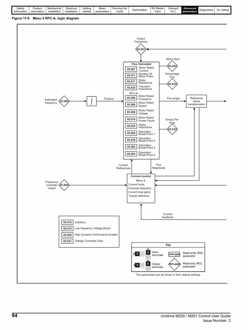
Safety information
Product information
Mechanical installation
Electrical installation
Getting started
Basic parameters
Running the motor
OptimizationNV Media
CardOnboard
PLCAdvanced
parametersDiagnostics UL Listing
Figure 11-9 Menu 5 RFC-A, logic diagram
03.004
RFC-A
05.006Motor RatedFrequency
05.008Motor RatedSpeed
05.009Motor RatedVoltage
05.010Motor RatedPower Factor
Motor RatedCurrent
05.011Number OfMotor Poles
05.017 StatorResistance
05.024 TransientInductance
05.025 StatorInductance
05.029
05.062
SaturationBreak-Point 1
SaturationBreak-Point 2
05.030
05.063
SaturationBreak-Point 3
SaturationBreak-Point 4
Flux Calculator
Current limits
Current control
Overload detection
Current loop gains
Torque reference
Menu 4
Referenceframe
transformation03.002
Estimatedfrequency
Frequencycontroller
output
Position
FluxMagnitude
CurrentReferences
Currentfeedback
05.001
Flux angle
05.012
05.015
05.026
05.031
Autotune
Low frequency Voltage Boost
High Dynamic Performance Enable
Voltage Controller Gain
OutputFrequency
mm.ppp
mm.ppp
Key
Read-write (RW)parameter
Read-only (RO)parameter
Inputterminals
Outputterminals
The parameters are all shown in their default settings
05.004
Motor Rpm
05.034
PercentageFlux
05.032
Torque PerAmp
94 Unidrive M200 / M201 Control User Guide Issue Number: 2

Safety information
Product information
Mechanical installation
Electrical installation
Getting started
Basic parameters
Running the motor
OptimizationNV Media
CardOnboard
PLCAdvanced
parametersDiagnostics UL Listing
04.002
04.017
04.001
RFC-A
05.009MotorRated Voltage
05.013 Flux OptimizationSelect
Flux Controller
05.018Maximum SwitchingFrequency
Modulator
05.003Power Calculation ( 3 x V x I)
05.002OutputVoltage
OutputPower
05.005
Voltage Reference
U
V
W
DC BusVoltage
CurrentMagnitude
MagnetisingCurrent
05.035Auto SwitchingFrequency ChangeDisable
05.037
SwitchingFrequency
05.038Minimum SwitchingFrequency
05.042Reverse OutputPhase Sequence
05.028 Flux ControlCompensationDisable
Output Frequency
Unidrive M200 / M201 Control User Guide 95Issue Number: 2

Safety information
Product information
Mechanical installation
Electrical installation
Getting started
Basic parameters
Running the motor
OptimizationNV Media
CardOnboard
PLCAdvanced
parametersDiagnostics UL Listing
ParameterRange () Default ()
TypeOL RFC-A OL RFC-A
05.001 Output Frequency ± 550.00 Hz RO Num ND NC PT FI
05.002 Output Voltage 0 to 930 V RO Num ND NC PT FI
05.003 Output Power VM_POWER kW RO Num ND NC PT FI
05.004 Motor Rpm ± 33000.0 rpm RO Num ND NC PT FI
05.005 D.C. Bus Voltage 0 to 1190 V RO Num ND NC PT FI
05.006 Motor Rated Frequency 0.00 to 550.00 Hz 50 Hz: 50.00 Hz, 60 Hz: 60.00 Hz RW Num RA US
05.007 Motor Rated Current 0.00 to Drive Rating A Maximum Heavy Duty Rating (11.032) RW Num RA US
05.008 Motor Rated Speed 0.0 to 33000.0 rpm
50 Hz: 1500.0 rpm
60 Hz: 1800.0 rpm
50 Hz: 1450.0 rpm
60 Hz: 1750.0 rpm
RW Num US
05.009 Motor Rated Voltage 0 to 765 V
110 V drive: 230 V, 200 V drive: 230 V400 V drive 50Hz: 400 V400 V drive 60Hz: 460 V
575 V drive: 575 V690 V drive: 690 V
RW Num RA US
05.010 Motor Rated Power Factor 0.00 to 1.00 0.85 RW Num RA US
05.011 Number Of Motor Poles* Auto (0) to 32 (16) Auto (0) RW Num US
05.012 Autotune 0 to 2 0 to 3 0 RW Num NC
05.013Dynamic V To F Select / Flux Optimization Select
0 to 1 0 RW Num US
05.014 Control Mode
Ur.S (0), Ur (1), Fd (2), Ur.Auto (3),
Ur.I (4), SrE (5), Fd.tAP (6)
Ur.I (4) RW Txt US
05.015 Low Frequency Voltage Boost 0.0 to 25.0 % 3.0 % RW Num US
05.017 Stator Resistance 0.0000 to 99.9999 Ω 0.0000 Ω RW Num RA US
05.018 Maximum Switching Frequency
0.667 (0), 1 (1), 2 (2), 3 (3), 4 (4),
6 (5), 8 (6), 12 (7), 16 (8) kHz
2 (2), 3 (3), 4 (4), 6 (5), 8 (6), 12 (7),
16 (8) kHz3 (3) kHz RW Txt RA US
05.019 High Stability Space Vector Modulation Off (0) or On (1) Off (0) RW Bit US
05.020 Over Modulation Enable Off (0) or On (1) Off (0) RW Bit US
05.021 Mechanical Load Test Level 0 to 100 % 0 % RW Bit US
05.024 Transient Inductance 0.000 to 500.000 mH 0.000 mH RW Num RA US
05.025 Stator Inductance 0.00 to 5000.00 mH 0.00 mH RW Num RA US
05.026 High Dynamic Performance Enable Off (0) or On (1) Off (0) RW Bit US
05.027 Enable Slip Compensation ±150.0 % 100.0 % RW Num US
05.028 Flux Control Compensation Disable Off (0) or On (1) Off (0) RW Bit US
05.029 Saturation Breakpoint 1 0.0 to 100.0 % 50.0 % RW Num US
05.030 Saturation Breakpoint 3 0.0 to 100.0 % 75.0 % RW Num US
05.031 Voltage Controller Gain 1 to 30 1 RW Num US
05.032 Torque Per Amp 0.00 to 500.00 Nm/A RO Num ND NC PT
05.033 Slip Compensation Limit 0.00 to 10.00 Hz 10.00 Hz RW Num US
05.034 Percentage Flux 0.0 to 150.0 % RO Num ND NC PT
05.035 Auto-switching Frequency Change Disable 0 to 1 0 RW Num US
05.036 Slip Compensation Filter64 (0), 128 (1),
256 (2), 512 (3) ms128 (1) ms RW Txt US
05.037 Switching Frequency
0.667 (0), 1 (1), 2 (2), 3 (3), 4 (4),
6 (5), 8 (6), 12 (7), 16 (8) kHz
2 (2), 3 (3), 4 (4), 6 (5), 8 (6), 12 (7),
16 (8) kHzRO Txt ND NC PT
05.038 Minimum Switching Frequency0 to VM_MAX_SWITCHING_
FREQUENCY kHz0.667 kHz (0) 2 kHz (2) RW Txt RA
05.040 Spin Start Boost 0.0 to 10.0 1.0 RW Num US
05.042 Reverse Output Phase Sequence Off (0) or On (1) Off (0) RW Bit US
05.059 Maximum Deadtime Compensation 0.000 to 10.000 µs RO Num NC PT US
05.060Current At Maximum DeadtimeCompensation
0.00 to 100.00 % RO Num NC PT US
05.061 Disable Deadtime Compensation Off (0) or On (1) Off (0) RW Bit US
05.062 Saturation Breakpoint 2 0.0 to 100.0 % 0.0 % RW Num US
05.063 Saturation Breakpoint 4 0.0 to 100.0 % 0.0 % RW Num US
05.074 Boost End Voltage 0.0 to 100.0 % 50.0 % RW Num US
05.075 Boost End Frequency 0.0 to 100.0 % 50.0 % RW Num US
05.076 Second Point Voltage 0.0 to 100.0 % 55.0 % RW Num US
05.077 Second Point Frequency 0.0 to 100.0 % 55.0 % RW Num US
05.078 Third point voltage 0.0 to 100.0 % 75.0 % RW Num US
05.079 Third point frequency 0.0 to 100.0 % 75.0 % RW Num US
96 Unidrive M200 / M201 Control User Guide Issue Number: 2
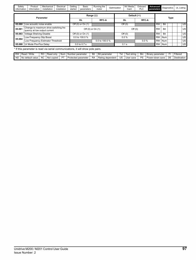
Safety information
Product information
Mechanical installation
Electrical installation
Getting started
Basic parameters
Running the motor
OptimizationNV Media
CardOnboard
PLCAdvanced
parametersDiagnostics UL Listing
* If this parameter is read via serial communications, it will show pole pairs.
05.080 Low acoustic noise enable Off (0) or On (1) Off (0) RW Bit US
05.081Change to maximum drive switching fre-quency at low output current
Off (0) or On (1) Off (0) RW Bit US
05.083 Voltage Shelving Disable Off (0) or On (1) Off (0) RW Bit US
05.084Low Frequency Slip Boost 0.0 to 100.0 % 0.0 % RW Num US
Low Frequency Estimator Threshold 0.0 to 100.0 % 0.0 % RW Num US
05.088 Ur Mode Pre-Flux Delay 0.0 to 0.7 s 0.1 s RW Num US
RW Read / Write RO Read only Num Number parameter Bit Bit parameter Txt Text string Bin Binary parameter FI Filtered
ND No default value NC Not copied PT Protected parameter RA Rating dependent US User save PS Power-down save DE Destination
ParameterRange () Default ()
TypeOL RFC-A OL RFC-A
Unidrive M200 / M201 Control User Guide 97Issue Number: 2

Safety information
Product information
Mechanical installation
Electrical installation
Getting started
Basic parameters
Running the motor
OptimizationNV Media
CardOnboard
PLCAdvanced
parametersDiagnostics UL Listing
11.7 Menu 6: Sequencer and clockFigure 11-10 Menu 6 logic diagram
06.012
Enable StopKey
01.011 Reference On
01.012 Reverse Select
01.013 Jog Select
RUN
STOP/RESET
Auxiliary
RESET
01.049
ReferenceSelectedIndicator
Logic 1
Open loop only
06.006 InjectionBraking Level
06.007 InjectionBraking Time
06.024 Reset Energy Meter
06.021Time Between FilterChanges
06.022Filter ChangeRequired / ChangeDone
06.027Energy CostPer kWh
Clock control
Time Before FilterChange Due
Running Cost06.028
Energy Meter
Inverter enable
RFC onlyMenu 2
Menu 3Ramp
Hard Frequencyreference
enable
enable
05.003OutputPower
Pr = 401.049
0 1
Sequencer
06.001
06.002
06.003
06.008
06.009
Stop Mode
Supply Loss Mode
Hold Zero Frequency
Catch ASpinning Motor
Enable SequencerLatching
06.019 Date/TimeSelector
0123
56
SetPo.upRunAcc.po
Re.PADSlot.1
06.02506.026
06.015
06.030
06.031
06.032
06.033
06.042
06.034
06.037
06.043
Jog Reverse
Run
Forward / Reverse
Run Reverse
Jog Forward
Run Forward
Drive Enable
Control Word
Control wordEnable
06.035
06.036
Forward Limit Switch
06.029HardwareEnable
Menu 8
T11 digital 2
T12 digital 3
T13 digital input 4
06.039
Not Stop
0
0
06.023
Reverse Limit Switch
mm.ppp
mm.ppp
Key
Read-write (RW)parameter
Read-only (RO)parameter
Inputterminals
Outputterminals
The parameters are all shown in their default settings
06.040
Limit Switch StopMode
06.052 Motor Pre-heatCurrent Magnitude
06.011Sequencer StateMachine Inputs
Mains/Phase LossDetection System
06.047Input Phase LossDetection Mode
06.048Supply LossDetection Level
06.051Hold SupplyLoss Active
10.015
SupplyLoss
06.018
06.017 Time
Day OfWeek
06.016 Date
06.020 Date FormatOutput
06.084 UTC Offset
98 Unidrive M200 / M201 Control User Guide Issue Number: 2

Safety information
Product information
Mechanical installation
Electrical installation
Getting started
Basic parameters
Running the motor
OptimizationNV Media
CardOnboard
PLCAdvanced
parametersDiagnostics UL Listing
ParameterRange () Default()
TypeOL RFC-A OL RFC-A
06.001 Stop Mode
CoASt (0), rP (1), rP.dc I (2), dc I (3),
td.dc I (4), diS (5)
CoASt (0), rP (1), rP.dc I (2), dc I (3),
td.dc I (4), diS (5), No.rP (6)
rP (1) RW Txt US
06.002 Limit Switch Stop Mode StoP (0), rP (1) rP (1) RW Txt US
06.003 Supply Loss Mode diS (0), rP.StoP (1), ridE.th (2), Lt.StoP (3) diS (0) RW Txt US
06.004 Start/Stop Logic Select 0 to 6 0 RW Num US
06.006 Injection Braking Level 0.0 to 150.0 % 100.0 % RW Num RA US
06.007 Injection Braking Time 0.0 to 100.0 s 1.0 s RW Num US
06.008 Hold Zero Frequency Off (0) or On (1) Off (0) RW Bit US
06.009 Catch A Spinning Motor diS (0), EnAbLE (1), Fr.OnLy (2), rv.OnLy (3) diS (0) RW Txt US
06.010 Enable Conditions 0 to 4087 RO Bin ND NC PT
06.011 Sequencer State Machine Inputs 0 to 127 RO Bin ND NC PT
06.012 Enable Stop Key Off (0) or On (1) Off (0) RW Bit US
06.013 Enable Auxiliary Key diS (0), Fd.rv (1), rEv (2) diS (0) RW Txt US
06.014 Disable Auto Reset On Enable Off (0) or On (1) Off (0) RW Bit US
06.015 Drive Enable Off (0) or On (1) On (1) RW Bit US
06.016 Date 00-00-00 to 31-12-99 RW Date ND NC PT
06.017 Time 00:00:00 to 23:59:59 RW Time ND NC PT
06.018 Day Of WeekSun (0), Non (1), tuE (2), UEd (3),thu (4),
Fri (5), SAt (6)RO Txt ND NC PT
06.019 Date/Time SelectorSEt (0), Po.uP (1), run (2), Acc.Po (3),
rE.PAd (5), SLot.1 (6)Po.uP (1) RW Txt US
06.020 Date Format Std (0), US (1) Std (0) RW Txt US
06.021 Time Between Filter Changes 0 to 30000 Hours 0 Hours RW Num US
06.022Filter Change Required /Change Done
Off (0) or On (1) RW Bit ND NC
06.023 Time Before Filter Change Due 0 to 30000 Hours RO Num ND NC PT PS
06.024 Reset Energy Meter Off (0) or On (1) Off (0) RW Bit
06.025 Energy Meter: MWh ±999.9 MWh RO Num ND NC PT PS
06.026 Energy Meter: kWh ±99.99 kWh RO Num ND NC PT PS
06.027 Energy Cost Per kWh 0.0 to 600.0 0.0 RW Num US
06.028 Running Cost ± 32000 RO Num ND NC PT
06.029 Hardware Enable Off (0) or On (1) RO Bit ND NC PT
06.030 Run Forward Off (0) or On (1) Off (0) RW Bit NC
06.031 Jog Forward Off (0) or On (1) Off (0) RW Bit NC
06.032 Run Reverse Off (0) or On (1) Off (0) RW Bit NC
06.033 Forward/Reverse Off (0) or On (1) Off (0) RW Bit NC
06.034 Run Off (0) or On (1) Off (0) RW Bit NC
06.035 Forward Limit Switch Off (0) or On (1) Off (0) RW Bit NC
06.036 Reverse Limit Switch Off (0) or On (1) Off (0) RW Bit NC
06.037 Jog Reverse Off (0) or On (1) Off (0) RW Bit NC
06.038 User Enable Off (0) or On (1) Off (0) RW Bit NC
06.039 Not Stop Off (0) or On (1) Off (0) RW Bit NC
06.040 Enable Sequencer Latching Off (0) or On (1) Off (0) RW Bit US
06.041 Drive Event Flags 0 to 3 0 RW Bin NC
06.042 Control Word 0 to 32767 0 RW Bin NC
06.043 Control Word Enable 0 to 1 0 RW Num US
06.045 Cooling Fan control 0 to 5 2 RW Num US
06.047 Input Phase Loss Detection Mode FuLL (0), rIPPLE (1), diS (2) FuLL (0) RW Txt US
06.048 Supply Loss Detection Level 0 to VM_SUPPLY_LOSS_LEVEL V
110 V drive: 205 V, 200 V drive: 205 V400 V drive: 410 V, 575 V drive: 540 V690 V drive: 540 V
RW Num RA US
06.051 Hold Supply Loss Active Off (0) or On (1) Off (0) RW Bit NC
06.052 Motor Pre-heat Current Magnitude 0 to 100 % 0 % RW Num US
06.058 Output Phase Loss Detection Time 0.5 (0) to 4 (3) s 0.5 (0) s RW Txt US
06.059 Output Phase Loss Detection Enable Off (0) or On (1) Off (0) RW Bit US
06.060 Standby Mode Enable Off (0) or On (1) Off (0) RW Bit US
06.061 Standby Mode Mask 0 to 15 0 RW Bin US
06.071 Slow Rectifier Charge Rate Enable Off (0) or On (1) Off (0) RW Bit US
06.073 Braking IGBT Lower Threshold 0 to VM_DC_VOLTAGE_SET V
110 V drive: 390 V, 200 V drive: 390 V400 V drive: 780 V, 575 V drive: 930 V690 V drive: 1120 V
RW Num RA US
Unidrive M200 / M201 Control User Guide 99Issue Number: 2
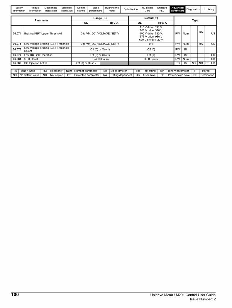
Safety information
Product information
Mechanical installation
Electrical installation
Getting started
Basic parameters
Running the motor
OptimizationNV Media
CardOnboard
PLCAdvanced
parametersDiagnostics UL Listing
06.074 Braking IGBT Upper Threshold 0 to VM_DC_VOLTAGE_SET V
110 V drive: 390 V, 200 V drive: 390 V400 V drive: 780 V, 575 V drive: 930 V690 V drive: 1120 V
RW NumRA
US
06.075 Low Voltage Braking IGBT Threshold 0 to VM_DC_VOLTAGE_SET V 0 V RW Num RA US
06.076Low Voltage Braking IGBT ThresholdSelect
Off (0) or On (1) Off (0) RW Bit
06.077 Low DC Link Operation Off (0) or On (1) Off (0) RW Bit US
06.084 UTC Offset 24.00 Hours 0.00 Hours RW Num US
06.089 DC Injection Active Off (0) or On (1) RO Bit ND NC PT US
ParameterRange () Default()
TypeOL RFC-A OL RFC-A
RW Read / Write RO Read only Num Number parameter Bit Bit parameter Txt Text string Bin Binary parameter FI Filtered
ND No default value NC Not copied PT Protected parameter RA Rating dependent US User save PS Power-down save DE Destination
100 Unidrive M200 / M201 Control User Guide Issue Number: 2

Safety information
Product information
Mechanical installation
Electrical installation
Getting started
Basic parameters
Running the motor
OptimizationNV Media
CardOnboard
PLCAdvanced
parametersDiagnostics UL Listing
11.8 Menu 7: Analog I/OFigure 11-11 Menu 7 logic diagram
??.??
Any variableparameter
??.??
07.020
AnalogOutput1Scaling
Analog Output 1
Post-rampreference
mm.ppp
mm.ppp
Key
Read-write (RW)parameter
Read-only (RO)parameter
Inputterminals
Outputterminals
The parameters are all shown in their default settings
07.007 07.008
AnalogInput 1Scaling
??.???
Anyunprotectedvariableparameter
??.???
V/f
x(-1)
Analog Input 1
07.009 AnalogInput 1 Invert
01.036
AnalogRef. 1
07.001
AnalogInput 1
++
07.030
Analog Input1 Offset
07.028
AnalogInput 1 Current
Loop Loss
Analog Input1 Mode
07.063 07.064
Analog Input 1MaximumReference
Analog Input 1At MaximumReference
07.062
07.061Analog Input1 MinimumReference
Analog Input 1At Minimum Reference
Analog Input 1Destination A
Analog Input1 Control
Analog Input 1Destination B 07.051
07.010
07.011 07.012
AnalogInput 2Scaling
??.???
Anyunprotectedvariableparameter
??.???
V/f
x(-1)
Analog Input 2
07.013 AnalogInput 2 Invert
07.002
AnalogInput 2
01.037
AnalogRef. 2
++
07.031
Analog Input2 Offset
Analog Input2 Mode
Analog Input 2At MaximumReference
07.066
07.065
Analog Input 2MaximumReference
Analog Input 2At Minimum Reference
Analog Input 2MinimumReference
Analog Input 2Destination A
Analog Input2 Control
Analog Input 2Destination B 07.052
07.014
07.06807.067
02.001
Analog Output1 Source A
Analog Output1 Source B
Analog Output1 Control
07.055
07.019
≥1
≥1
≥1
07.090
07.094
07.099
Unidrive M200 / M201 Control User Guide 101Issue Number: 2

Safety information
Product information
Mechanical installation
Electrical installation
Getting started
Basic parameters
Running the motor
OptimizationNV Media
CardOnboard
PLCAdvanced
parametersDiagnostics UL Listing
Figure 11-12 Menu 7 logic diagram: Thermistor input
ThS trip detect
Th trip detect
Thermistor Type (07.046)Thermistor Trip Threshold (07.048)
Thermistor Reset Threshold (07.049)
Resistance to temperature
conversion
07.050
ThermistorTemperature
0 to 3
4
07.046 Thermistor Type
07.047
Thermistor
feedback
1, 2 or 3
0
08.035 DI/O 05 Select
Digital input 5
14
1
Digital Input 5
0V
ThermistorInput
Menu 3 Frequency Input
4
mm.ppp
mm.ppp
Key
Read-write (RW)parameter
Read-only (RO)parameter
Inputterminals
Outputterminals
The parameters are all shown in their default settings
102 Unidrive M200 / M201 Control User Guide Issue Number: 2
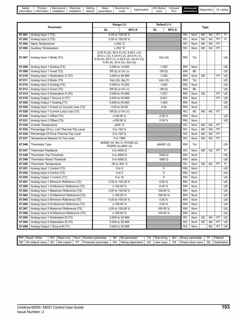
Safety information
Product information
Mechanical installation
Electrical installation
Getting started
Basic parameters
Running the motor
OptimizationNV Media
CardOnboard
PLCAdvanced
parametersDiagnostics UL Listing
ParameterRange () Default ()
TypeOL RFC-A OL RFC-A
07.001 Analog Input 1 (T2) 0.00 to 100.00 % RO Num ND NC PT FI
07.002 Analog Input 2 (T5) 0.00 to 100.00 % RO Num ND NC PT FI
07.004 Stack Temperature ± 250 °C RO Num ND NC PT
07.005 Auxiliary Temperature ± 250 °C RO Num ND NC PT
07.007 Analog Input 1 Mode (T2)
4-20.S (-6), 20-4.S (-5), 4-20.L (-4), 20-4.L (-3), 4-20.H (-2), 20-4.H (-1),
0-20 (0), 20-0 (1), 4-20.tr (2), 20-4.tr (3), 4-20 (4), 20-4 (5), VoLt (6)
VoLt (6) RW Txt US
07.008 Analog Input 1 Scaling (T2) 0.000 to 10.000 1.000 RW Num US
07.009 Analog Input 1 Invert (T2) Off (0) or On (1) Off (0) RW Bit US
07.010 Analog Input 1 Destination A (T2) 0.000 to 30.999 1.036 RW Num DE PT US
07.011 Analog Input 2 Mode (T5) VoLt (6), dIg (7) VoLt (6) RW Txt US
07.012 Analog Input 2 Scaling (T5) 0.000 to 10.000 1.000 RW Num US
07.013 Analog Input 2 Invert (T5) Off (0) or On (1) Off (0) RW Bit US
07.014 Analog Input 2 Destination A (T5) 0.000 to 30.999 1.037 RW Num DE PT US
07.019 Analog Output 1 Source A (T7) 0.000 to 30.999 2.001 RW Num PT US
07.020 Analog Output 1 Scaling (T7) 0.000 to 40.000 1.000 RW Num US
07.026 Analog Input 1 Preset on Current Loss (T2) 4.00 to 20.00 4.00 RW Num US
07.028 Analog Input 1 Current Loop Loss (T2) Off (0) or On (1) RO Bit ND NC PT
07.030 Analog Input 1 Offset (T2) ±100.00 % 0.00 % RW Num US
07.031 Analog Input 2 Offset (T5) ±100.00 % 0.00 % RW Num US
07.034 Inverter Temperature ±250 °C RO Num ND NC PT
07.035 Percentage Of d.c. Link Thermal Trip Level 0 to 100 % RO Num ND NC PT
07.036 Percentage Of Drive Thermal Trip Level 0 to 100 % RO Num ND NC PT
07.037 Temperature Nearest To Trip Level 0 to 1999 RO Num ND NC PT
07.046 Thermistor Typed44081 (0), 84 (1), Pt1000 (2),
Pt2000 (3),othEr (4)d44081 (0) RW Txt US
07.047 Thermistor Feedback 0 to 4000 Ω RO Num ND NC PT FI
07.048 Thermistor Trip Threshold 0 to 4000 Ω 3300 Ω RW Num US
07.049 Thermistor Reset Threshold 0 to 4000 Ω 1800 Ω RW Num US
07.050 Thermistor Temperature -50 to 300 °C RO Num ND NC PT FI
07.051 Analog Input 1 Control (T2) 0 to 5 0 RW Num US
07.052 Analog Input 2 Control (T5) 0 to 5 0 RW Num US
07.055 Analog Output 1 Control (T7) 0 to 15 0 RW Num US
07.061 Analog Input 1 Minimum Reference (T2) 0.00 to 100.00 % 0.00 % RW Num US
07.062 Analog Input 1 At Minimum Reference (T2) ± 100.00 % 0.00 % RW Num US
07.063 Analog Input 1 Maximum Reference (T2) 0.00 to 100.00 % 100.00 % RW Num US
07.064 Analog Input 1 At Maximum Reference (T2) ± 100.00 % 100.00 % RW Num US
07.065 Analog Input 2 Minimum Reference (T5) 0.00 to 100.00 % 0.00 % RW Num US
07.066 Analog Input 2 At Minimum Reference (T5) ± 100.00 % 0.00 % RW Num US
07.067 Analog Input 2 Maximum Reference (T5) 0.00 to 100.00 % 100.00 % RW Num US
07.068 Analog Input 2 At Maximum Reference (T5) ± 100.00 % 100.00 % RW Num US
07.090 Analog Input 1 Destination B (T2) 0.000 to 30.999 RO Num DE NC PT US
07.094 Analog Input 2 Destination B (T5) 0.000 to 30.999 RO Num DE NC PT US
07.099 Analog Output 1 Source B (T7) 0.000 to 30.999 RO Num NC PT US
RW Read / Write RO Read only Num Number parameter Bit Bit parameter Txt Text string Bin Binary parameter FI Filtered
ND No default value NC Not copied PT Protected parameter RA Rating dependent US User save PS Power-down save DE Destination
Unidrive M200 / M201 Control User Guide 103Issue Number: 2

Safety information
Product information
Mechanical installation
Electrical installation
Getting started
Basic parameters
Running the motor
OptimizationNV Media
CardOnboard
PLCAdvanced
parametersDiagnostics UL Listing
11.9 Menu 8: Digital I/OFigure 11-13 Menu 8 logic diagram
T10 Digital I/O01 Output Mode
08.031
??.???
??.???
Anyunprotectedbit parameter
??.???
??.???
Any bitparameter
x(-1)
x(-1)
08.011 T10 DigitalI/O 1 Invert
T10 Digital I/O1 State
08.001 10.003
At ZeroFrequency
T10 Digital I/O 1
mm.ppp
mm.ppp
Key
Read-write (RW)parameter
Read-only (RO)parameter
Inputterminals
Outputterminals
The parameters are all shown in their default settings
Frequency orPWM output
0 or 1
2 or 3
T10 Digital I/O 1source / destination A
08.021
T10 DI/O 01 Source/ Destination B
T11 Digital input 2
08.002T11 Digitalinput 2 state
T11 Digitalinput 2 invert
??.???
Any unprotected
Userenable
bit parameter
T11 DI 02Destination B
T11 DI 2 Control
T11 Digital Input 02Destination A
??.???x(-1)
06.038
08.082
08.02208.012
≥1
≥1
T10 DI1 Control T10 DO1 Control
08.09108.081
08.121
08.122
104 Unidrive M200 / M201 Control User Guide Issue Number: 2

Safety information
Product information
Mechanical installation
Electrical installation
Getting started
Basic parameters
Running the motor
OptimizationNV Media
CardOnboard
PLCAdvanced
parametersDiagnostics UL Listing
??.???
Any unprotectedbit parameter
??.???
08.013
T12 DigitalInput 3 InvertT12 Digital
Input 3 State08.003
06.030
Run forward
T12 Digital Input 3
x(-1)
T12 DI3 Control
08.083
08.023
T12 DI 03Destination B
T12 Digital input3 destination A
??.???
Any unprotectedbit parameter
??.???
08.014
T13 DigitalInput 4 InvertT13 Digital
Input 4 State08.004
06.032
Run reverse
T13 Digital Input 4
x(-1)
T13 DI4 Control
08.084
08.024
T13 DI 04Destination B
T13 Digital input4 destination A
??.???
Any unprotectedbit parameter
??.???
08.01508.035
T14 DigitalInput 5 Invert
T14 DigitalInput 5 Select
T14 DigitalInput 5 State
08.005
01.041
ReferenceSelect Flag 1
T14 Digital Input 5
Thermistor mode
x(-1)
T14 DI5 Control
08.085
08.025
T14 DI 05Destination B
T14 Digital input5 destination A
0
1 to 3
Frequencyinput
1
≥1
≥1
≥1
08.123
08.124
08.125
Unidrive M200 / M201 Control User Guide 105Issue Number: 2

Safety information
Product information
Mechanical installation
Electrical installation
Getting started
Basic parameters
Running the motor
OptimizationNV Media
CardOnboard
PLCAdvanced
parametersDiagnostics UL Listing
Figure 11-14 Menu 8 logic (relay)
Figure 11-15 Menu 8 logic (Remote Keypad RTC)
* The auxiliary button is available with the Remote Keypad RTC.
08.008
Relay 1Output State
0V
x(-1)
08.018
??.???
Any bitparameter
Relay 1source B
Relay 1
Relay 1Invert
control
Relay 1 OutputSource A
??.???
10.001
Drive OK
08.098
08.028
08.128
08.041
Run button
Toggle
Auxiliary Button*
08.042
Toggle
KeypadAuxiliary Button
Destination
08.051
x(-1)
x(-1)
Keypad AuxiliaryButton State
Keypad Run ButtonInvert/Toggle
Keypad RunButton State
08.061
00.000
Keypad RunButton Destination
??.???
??.???
Anyunprotectedbit parameter
08.062
00.000
??.???
??.???
Anyunprotectedbit parameter
08.052
Keypad AuxiliaryButton Invert/Toggle
mm.ppp
mm.ppp
Key
Read-write (RW)parameter
Read-only (RO)parameter
Inputterminals
Outputterminals
The parameters are all shown in their default settings
Stop Button 08.044
Keypad StopButton State
106 Unidrive M200 / M201 Control User Guide Issue Number: 2

Safety information
Product information
Mechanical installation
Electrical installation
Getting started
Basic parameters
Running the motor
OptimizationNV Media
CardOnboard
PLCAdvanced
parametersDiagnostics UL Listing
ParameterRange () Default ()
TypeOL RFC-A OL RFC-A
08.001 Digital I/O 1 State (T10) Off (0) or On (1) RO Bit ND NC PT
08.002 Digital Input 2 State (T11) Off (0) or On (1) RO Bit ND NC PT
08.003 Digital Input 3 State (T12) Off (0) or On (1) RO Bit ND NC PT
08.004 Digital Input 4 State (T13) Off (0) or On (1) RO Bit ND NC PT
08.005 Digital Input 5 State (T14) Off (0) or On (1) RO Bit ND NC PT
08.008 Relay 1 Output State Off (0) or On (1) RO Bit ND NC PT
08.011 Digital I/O 1 Invert (T10) Not.Inv (0), InvErt (1) Not.Inv (0) RW Txt US
08.012 Digital Input 2 Invert (T11) Not.Inv (0), InvErt (1) Not.Inv (0) RW Txt US
08.013 Digital Input 3 Invert (T12) Not.Inv (0), InvErt (1) Not.Inv (0) RW Txt US
08.014 Digital Input 4 Invert (T13) Not.Inv (0), InvErt (1) Not.Inv (0) RW Txt US
08.015 Digital Input 5 Invert (T14) Not.Inv (0), InvErt (1) Not.Inv (0) RW Txt US
08.018 Relay 1 Invert Not.Inv (0), InvErt (1) Not.Inv (0) RW Txt US
08.020 Digital I/O Read Word 0 to 2048 RO Num ND NC PT
08.021 Digital IO1 Source / Destination A (T10) 0.000 to 30.999 10.003 RW Num DE PT US
08.022 Digital Input 02 Destination A (T11) 0.000 to 30.999 6.038 RW Num DE PT US
08.023 Digital Input 03 Destination A (T12) 0.000 to 30.999 6.030 RW Num DE PT US
08.024 Digital Input 04 Destination A (T13) 0.000 to 30.999 6.032 RW Num DE PT US
08.025 Digital Input 05 Destination A (T14) 0.000 to 30.999 1.041 RW Num DE PT US
08.028 Relay 1 Output Source A 0.000 to 30.999 10.001 RW Num PT US
08.031 Digital I/O 01 Output Mode (T10) InPut (0), OutPut (1), Fr (2), PuLSE (3) OutPut (1) RW Txt US
08.035 Digital Input 5 Select (T14)InPut (0), th.Sct (1), th (2),
th.Notr (3), Fr (4)InPut (0) RW Txt US
08.041 Keypad Run Button State Off (0) or On (1) RO Bit ND NC PT
08.042 Keypad Auxiliary Button State Off (0) or On (1) RO Bit ND NC PT
08.043 24 V Supply Input State Off (0) or On (1) RO Bit ND NC PT
08.044 Keypad Stop Button State Off (0) or On (1) RO Bit ND NC PT
08.051 Keypad Run Button Invert / Toggle Not.Inv (0), InvErt (1), toggLE (2) Not.Inv (0) RW Txt US
08.052 Keypad Auxiliary Button Invert / Toggle Not.Inv (0), InvErt (1), toggLE (2) Not.Inv (0) RW Txt US
08.053 24 V Supply Input Invert Not.Inv (0), InvErt (1), Not.Inv (0) RW Txt US
08.061 Keypad Run Button Destination 0.000 to 30.999 0.000 RW Num DE PT US
08.062 Keypad Auxiliary Button Destination 0.000 to 30.999 0.000 RW Num DE PT US
08.063 24 V Supply Input Destination 0.000 to 30.999 0.000 RW Num DE PT US
08.081 DI1 Control (T10) 0 to 26 0 RW Num US
08.082 DI2 Control (T11) 0 to 26 0 RW Num US
08.083 DI3 Control (T12) 0 to 26 0 RW Num US
08.084 DI4 Control (T13) 0 to 26 0 RW Num US
08.085 DI5 Control (T14) 0 to 26 0 RW Num US
08.091 DO1 Control (T10) 0 to 21 0 RW Num US
08.098 Relay 1 Control 0 to 21 0 RW Num US
08.121 DI/O 01 Source / Destination B (T10) 0.000 to 30.999 RO Num DE NC PT US
08.122 DI 02 Destination B (T11) 0.000 to 30.999 RO Num DE NC PT US
08.123 DI 03 Destination B (T12) 0.000 to 30.999 RO Num DE NC PT US
08.124 DI 04 Destination B (T13) 0.000 to 30.999 RO Num DE NC PT US
08.125 DI 05 Destination B (T14) 0.000 to 30.999 RO Num DE NC PT US
08.128 Relay 01 Source B 0.000 to 30.999 0.000 RO Num NC PT US
RW Read / Write RO Read only Num Number parameter Bit Bit parameter Txt Text string Bin Binary parameter FI Filtered
ND No default value NC Not copied PT Protected parameter RA Rating dependent US User save PS Power-down save DE Destination
Unidrive M200 / M201 Control User Guide 107Issue Number: 2

Safety information
Product information
Mechanical installation
Electrical installation
Getting started
Basic parameters
Running the motor
OptimizationNV Media
CardOnboard
PLCAdvanced
parametersDiagnostics UL Listing
11.10 Menu 9: Programmable logic, motorized pot, binary sum and timersFigure 11-16 Menu 9 logic diagram: Programmable logic
??.???
Anyunprotectedbitparameter
??.???
09.010
Logic Function1 Destination
Logic Function1 Source 2
??.???
Any bitparameter
??.??? x(-1)
09.004
09.005Logic Function 1Source 1 Invert
Logic Function 1Source 1
??.???
Any bitparameter
??.??? x(-1)
09.006
09.007Logic Function 1Source 2 Invert
09.008
Logic Function 1Output Invert
09.009
Logic Function1 Delay
x(-1)
Logic Function1 Output
09.001
??.???
Anyunprotectedbitparameter
??.???
09.020
Logic Function2 Destination
??.???
Any bitparameter
??.??? x(-1)
09.014 Logic Function 2Source 1
09.015Logic Function 2Source 1 Invert
??.???
Any bitparameter
??.??? x(-1)
09.016 Logic Function 2Source 2
09.017Logic Function 2Source 2 Invert
09.018
Logic Function 2Output Invert
09.019
Logic Function2 Delay
x(-1)
Logic Function2 Output
09.002
mm.ppp
mm.ppp
Key
Read-write (RW)parameter
Read-only (RO)parameter
Inputterminals
Outputterminals
XX
XX
The parameters are all shown in their default settings
108 Unidrive M200 / M201 Control User Guide Issue Number: 2

Safety information
Product information
Mechanical installation
Electrical installation
Getting started
Basic parameters
Running the motor
OptimizationNV Media
CardOnboard
PLCAdvanced
parametersDiagnostics UL Listing
Figure 11-17 Menu 9 logic diagram: Motorized pot and binary sum
09.030
Binary SumTwos
09.029
Binary SumOnes
09.031
Binary SumFours
09.032
Binary SumOutput
??.???
Anyunprotectedbitparameter
??.???
09.033
Binary SumDestination
09.024
Motorized Pot.Scaling
09.025
Motorized Pot.Destination
09.023
MotorizedPot. Rate
??.???
Anyunprotectedvariableparameter
??.???
09.027
Motorized Pot.Down
09.026
Motorized Pot.Up
M
09.003
Motorized Pot.Output
09.022
MotorizedPot. BipolarSelect
09.02109.028
Motorized Pot.Reset
Motorized Pot.Mode
++
09.034
Binary SumOffset
Function disabled if setto a non valid destination
Function disabled if setto a non valid destination
mm.ppp
mm.ppp
Key
Read-write (RW)parameter
Read-only (RO)parameter
Inputterminals
Outputterminals
XX
XX
The parameters are all shown in their default settings
Unidrive M200 / M201 Control User Guide 109Issue Number: 2
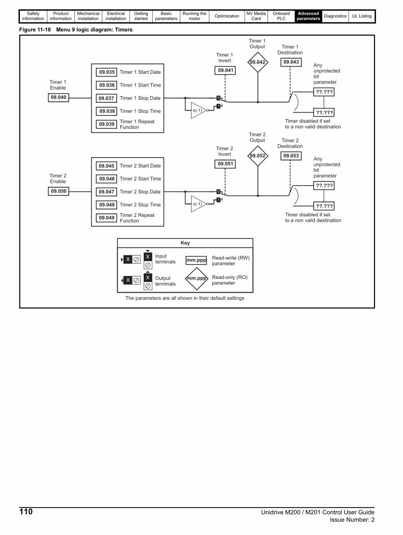
Safety information
Product information
Mechanical installation
Electrical installation
Getting started
Basic parameters
Running the motor
OptimizationNV Media
CardOnboard
PLCAdvanced
parametersDiagnostics UL Listing
Figure 11-18 Menu 9 logic diagram: Timers
??.???
Anyunprotectedbitparameter
??.???
09.043
09.041
x(-1)
09.042
09.040
09.035 Timer 1 Start Date
09.036 Timer 1 Start Time
09.037 Timer 1 Stop Date
09.038 Timer 1 Stop Time
09.039Timer 1 RepeatFunction
Timer 1Enable
Timer 1Invert
Timer 1Output Timer 1
Destination
??.???
Anyunprotectedbitparameter
??.???
09.053
09.051
x(-1)
09.052
09.050
09.045 Timer 2 Start Date
09.046 Timer 2 Start Time
09.047 Timer 2 Stop Date
09.048 Timer 2 Stop Time
09.049Timer 2 RepeatFunction
Timer 2Enable
Timer 2Invert
Timer 2Output Timer 2
Destination
Timer disabled if setto a non valid destination
Timer disabled if setto a non valid destination
mm.ppp
mm.ppp
Key
Read-write (RW)parameter
Read-only (RO)parameter
Inputterminals
Outputterminals
XX
XX
The parameters are all shown in their default settings
110 Unidrive M200 / M201 Control User Guide Issue Number: 2

Safety information
Product information
Mechanical installation
Electrical installation
Getting started
Basic parameters
Running the motor
OptimizationNV Media
CardOnboard
PLCAdvanced
parametersDiagnostics UL Listing
ParameterRange() Default()
TypeOL RFC-A OL RFC-A
09.001 Logic Function 1 Output Off (0) or On (1) RO Bit ND NC PT
09.002 Logic Function 2 Output Off (0) or On (1) RO Bit ND NC PT
09.003 Motorized Pot Output ±100.00 % RO Num ND NC PT PS
09.004 Logic Function 1 Source 1 0.000 to 30.999 0.000 RW Num PT US
09.005 Logic Function 1 Source 1 Invert Off (0) or On (1) Off (0) RW Bit US
09.006 Logic Function 1 Source 2 0.000 to 30.999 0.000 RW Num PT US
09.007 Logic Function 1 Source 2 Invert Off (0) or On (1) Off (0) RW Bit US
09.008 Logic Function 1 Output Invert Off (0) or On (1) Off (0) RW Bit US
09.009 Logic Function 1 Delay ± 25.0 s 0.0 s RW Num US
09.010 Logic Function 1 Destination 0.000 to 30.999 0.000 RW Num DE PT US
09.014 Logic Function 2 Source 1 0.000 to 30.999 0.000 RW Num PT US
09.015 Logic Function 2 Source 1 Invert Off (0) or On (1) Off (0) RW Bit US
09.016 Logic Function 2 Source 2 0.000 to 30.999 0.000 RW Num PT US
09.017 Logic Function 2 Source 2 Invert Off (0) or On (1) Off (0) RW Bit US
09.018 Logic Function 2 Output Invert Off (0) or On (1) Off (0) RW Bit US
09.019 Logic Function 2 Delay ± 25.0 s 0.0 s RW Num US
09.020 Logic Function 2 Destination 0.000 to 30.999 0.000 RW Num DE PT US
09.021 Motorized Pot Mode 0 to 4 0 RW Num US
09.022 Motorized Pot Bipolar Select Off (0) or On (1) Off (0) RW Bit US
09.023 Motorized Pot Rate 0 to 250 s 20 s RW Num US
09.024 Motorized Pot Scaling 0.000 to 4.000 1.000 RW Num US
09.025 Motorized Pot Destination 0.000 to 30.999 0.000 RW Num DE PT US
09.026 Motorized Pot Up Off (0) or On (1) Off (0) RW Bit NC
09.027 Motorized Pot Down Off (0) or On (1) Off (0) RW Bit NC
09.028 Motorized Pot Reset Off (0) or On (1) Off (0) RW Bit NC
09.029 Binary Sum Ones Off (0) or On (1) Off (0) RW Bit
09.030 Binary Sum Twos Off (0) or On (1) Off (0) RW Bit
09.031 Binary Sum Fours Off (0) or On (1) Off (0) RW Bit
09.032 Binary Sum Output 0 to 255 RO Num ND NC PT
09.033 Binary Sum Destination 0.000 to 30.999 0.000 RW Num DE PT US
09.034 Binary Sum Offset 0 to 248 0 RW Num US
09.035 Timer 1 Start Date 00-00-00 to 31-12-99 00-00-00 RW Date US
09.036 Timer 1 Start Time 00:00:00 to 23:59:59 00:00:00 RW Time US
09.037 Timer 1 Stop Date 00-00-00 to 31-12-99 00-00-00 RW Date US
09.038 Timer 1 Stop Time 00:00:00 to 23:59:59 00:00:00 RW Time US
09.039 Timer 1 Repeat FunctionNonE (0), 1 (1), 2 (2), 3 (3),
4 (4), 5 (5), 6 (6), 7 (7)NonE (0) RW Txt US
09.040 Timer 1 Enable Off (0) or On (1) Off (0) RW Bit US
09.041 Timer 1 Invert Off (0) or On (1) Off (0) RW Bit US
09.042 Timer 1 Output Off (0) or On (1) RO Bit ND NC PT
09.043 Timer 1 Destination 0.000 to 30.999 0.000 RW Num DE PT US
09.045 Timer 2 Start Date 00-00-00 to 31-12-99 00-00-00 RW Date US
09.046 Timer 2 Start Time 00:00:00 to 23:59:59 00:00:00 RW Time US
09.047 Timer 2 Stop Date 00-00-00 to 31-12-99 00-00-00 RW Date US
09.048 Timer 2 Stop Time 00:00:00 to 23:59:59 00:00:00 RW Time US
09.049 Timer 2 Repeat FunctionNonE (0), 1 (1), 2 (2), 3 (3), 4 (4),
5 (5), 6 (6), 7 (7)NonE (0) RW Txt US
09.050 Timer 2 Enable Off (0) or On (1) Off (0) RW Bit US
09.051 Timer 2 Invert Off (0) or On (1) Off (0) RW Bit US
09.052 Timer 2 Output Off (0) or On (1) RO Bit ND NC PT
09.053 Timer 2 Destination 0.000 to 30.999 0.000 RW Num DE PT US
RW Read / Write RO Read only Num Number parameter Bit Bit parameter Txt Text string Bin Binary parameter FI Filtered
ND No default value NC Not copied PT Protected parameter RA Rating dependent US User save PS Power-down save DE Destination
IP IP address Mac Mac address Date Date parameter Time Time parameter SMP Slot,menu,parameter Chr Character parameter Ver Version number
Unidrive M200 / M201 Control User Guide 111Issue Number: 2

Safety information
Product information
Mechanical installation
Electrical installation
Getting started
Basic parameters
Running the motor
OptimizationNV Media
CardOnboard
PLCAdvanced
parametersDiagnostics UL Listing
11.11 Menu 10: Status and trips
ParameterRange () Default ()
TypeOL RFC-A OL RFC-A
10.001 Drive OK Off (0) or On (1) RO Bit ND NC PT
10.002 Drive Active Off (0) or On (1) RO Bit ND NC PT
10.003 Zero Frequency Off (0) or On (1) RO Bit ND NC PT
10.004 Running At Or Below Minimum Frequency Off (0) or On (1) RO Bit ND NC PT
10.005 Below Set Frequency Off (0) or On (1) RO Bit ND NC PT
10.006 At Frequency Off (0) or On (1) RO Bit ND NC PT
10.007 Above Set Frequency Off (0) or On (1) RO Bit ND NC PT
10.008 Rated Load Reached Off (0) or On (1) RO Bit ND NC PT
10.009 Current Limit Active Off (0) or On (1) RO Bit ND NC PT
10.010 Regenerating Off (0) or On (1) RO Bit ND NC PT
10.011 Braking IGBT Active Off (0) or On (1) RO Bit ND NC PT
10.012 Braking Resistor Alarm Off (0) or On (1) RO Bit ND NC PT
10.013 Reverse Direction Commanded Off (0) or On (1) RO Bit ND NC PT
10.014 Reverse Direction Running Off (0) or On (1) RO Bit ND NC PT
10.015 Supply Loss Off (0) or On (1) RO Bit ND NC PT
10.016 Under Voltage Active Off (0) or On (1) RO Bit ND NC PT
10.017 Motor Overload Alarm Off (0) or On (1) RO Bit ND NC PT
10.018 Drive Over-temperature Alarm Off (0) or On (1) RO Bit ND NC PT
10.019 Drive Warning Off (0) or On (1) RO Bit ND NC PT
10.020 Trip 0 0 to 255 RO Txt ND NC PT PS
10.021 Trip 1 0 to 255 RO Txt ND NC PT PS
10.022 Trip 2 0 to 255 RO Txt ND NC PT PS
10.023 Trip 3 0 to 255 RO Txt ND NC PT PS
10.024 Trip 4 0 to 255 RO Txt ND NC PT PS
10.025 Trip 5 0 to 255 RO Txt ND NC PT PS
10.026 Trip 6 0 to 255 RO Txt ND NC PT PS
10.027 Trip 7 0 to 255 RO Txt ND NC PT PS
10.028 Trip 8 0 to 255 RO Txt ND NC PT PS
10.029 Trip 9 0 to 255 RO Txt ND NC PT PS
10.030 Braking Resistor Rated Power 0.0 to 99999.9 kW 0.0 kW RW Num US
10.031 Braking Resistor Thermal Time Constant 0.00 to 1500.00 s 0.00 s RW Num US
10.032 External Trip Off (0) or On (1) Off (0) RW Bit NC
10.033 Drive Reset Off (0) or On (1) Off (0) RW Bit NC
10.034 Number Of Auto-reset AttemptsNonE (0), 1 (1), 2 (2), 3 (3), 4 (4),
5 (5),inF (6)NonE (0) RW Txt US
10.035 Auto-reset Delay 0.0 to 600.0 s 1.0 s RW Num US
10.036 Auto-reset Hold Drive OK Off (0) or On (1) Off (0) RW Bit US
10.037 Action On Trip Detection 0 to 31 0 RW Num US
10.038 User Trip 0 to 255 RW Num ND NC
10.039 Braking Resistor Thermal Accumulator 0.0 to 100.0 % RO Num ND NC PT
10.040 Status Word 0 to 32767 RO Num ND NC PT
10.041 Trip 0 Date 00-00-00 to 31-12-99 RO Date ND NC PT PS
10.042 Trip 0 Time 00:00:00 to 23:59:59 RO Time ND NC PT PS
10.043 Trip 1 Date 00-00-00 to 31-12-99 RO Date ND NC PT PS
10.044 Trip 1 Time 00:00:00 to 23:59:59 RO Time ND NC PT PS
10.045 Trip 2 Date 00-00-00 to 31-12-99 RO Date ND NC PT PS
10.046 Trip 2 Time 00:00:00 to 23:59:59 RO Time ND NC PT PS
10.047 Trip 3 Date 00-00-00 to 31-12-99 RO Date ND NC PT PS
10.048 Trip 3 Time 00:00:00 to 23:59:59 RO Time ND NC PT PS
10.049 Trip 4 Date 00-00-00 to 31-12-99 RO Date ND NC PT PS
10.050 Trip 4 Time 00:00:00 to 23:59:59 RO Time ND NC PT PS
10.051 Trip 5 Date 00-00-00 to 31-12-99 RO Date ND NC PT PS
10.052 Trip 5 Time 00:00:00 to 23:59:59 RO Time ND NC PT PS
10.053 Trip 6 Date 00-00-00 to 31-12-99 RO Date ND NC PT PS
10.054 Trip 6 Time 00:00:00 to 23:59:59 RO Time ND NC PT PS
10.055 Trip 7 Date 00-00-00 to 31-12-99 RO Date ND NC PT PS
10.056 Trip 7 Time 00:00:00 to 23:59:59 RO Time ND NC PT PS
10.057 Trip 8 Date 00-00-00 to 31-12-99 RO Date ND NC PT PS
10.058 Trip 8 Time 00:00:00 to 23:59:59 RO Time ND NC PT PS
112 Unidrive M200 / M201 Control User Guide Issue Number: 2

Safety information
Product information
Mechanical installation
Electrical installation
Getting started
Basic parameters
Running the motor
OptimizationNV Media
CardOnboard
PLCAdvanced
parametersDiagnostics UL Listing
10.059 Trip 9 Date 00-00-00 to 31-12-99 RO Date ND NC PT PS
10.060 Trip 9 Time 00:00:00 to 23:59:59 RO Time ND NC PT PS
10.061 Braking Resistor Resistance 0.00 to 10000.00 Ω 0.00 Ω RW Num US
10.064 Remote Keypad Battery Low Off (0) or On (1) RO Bit ND NC PT
10.065 Autotune Active Off (0) or On (1) RO Bit ND NC PT
10.066 Limit Switch Active Off (0) or On (1) RO Bit ND NC PT
10.068 Hold Drive Healthy On Under Voltage Off (0) or On (1) Off (0) RW Bit US
10.069 Additional Status Bits 0 to 2047 RO Num ND NC PT
10.070 Trip 0 Sub-trip Number 0 to 65535 RO Num ND NC PT PS
10.071 Trip 1 Sub-trip Number 0 to 65535 RO Num ND NC PT PS
10.072 Trip 2 Sub-trip Number 0 to 65535 RO Num ND NC PT PS
10.073 Trip 3 Sub-trip Number 0 to 65535 RO Num ND NC PT PS
10.074 Trip 4 Sub-trip Number 0 to 65535 RO Num ND NC PT PS
10.075 Trip 5 Sub-trip Number 0 to 65535 RO Num ND NC PT PS
10.076 Trip 6 Sub-trip Number 0 to 65535 RO Num ND NC PT PS
10.077 Trip 7 Sub-trip Number 0 to 65535 RO Num ND NC PT PS
10.078 Trip 8 Sub-trip Number 0 to 65535 RO Num ND NC PT PS
10.079 Trip 9 Sub-trip Number 0 to 65535 RO Num ND NC PT PS
10.080 Stop Motor Off (0) or On (1) RO Bit ND NC PT
10.081 Phase Loss Off (0) or On (1) RO Bit ND NC PT
10.090 Drive Ready Off (0) or On (1) RO Bit ND NC PT
10.101 Drive Status
Inh (0), rdy (1), StoP (2), rES (3), rES (4), S.LoSS (5), rES (6), dc.inJ (7), rES (8), Error (9),
ActivE (10), rES (11), rES (12), rES (13), HEAt (14), UU (15)
RO Txt ND NC PT
10.102 Trip Reset Source 0 to 1023 RO Num ND NC PT PS
10.103 Trip Time Identifier -2147483648 to 2147483647 ms RO Num ND NC PT
10.104 Active Alarm
NonE (0), br.rES (1), OV.Ld (2), rES (3), d.OV.Ld (4), tuning (5),
LS (6), rES (7), rES (8), OPt.AL (9), rES (10), rES (11),
rES(12), Lo.AC (13), I.AC.Lt (14), 24.LoSt (15)
RO Txt ND NC PT
10.106 Potential Drive Damage Conditions 0 to 3 RO Bin ND NC PT PS
10.107 Low AC Alarm Off (0) or On (1) RO Bit ND NC PT
10.108 Reversed cooling fan detected Off (0) or On (1) RO Bit ND NC PT
ParameterRange () Default ()
TypeOL RFC-A OL RFC-A
RW Read / Write RO Read only Num Number parameter Bit Bit parameter Txt Text string Bin Binary parameter FI Filtered
ND No default value NC Not copied PT Protected parameter RA Rating dependent US User save PS Power-down save DE Destination
IP IP address Mac Mac address Date Date parameter Time Time parameter SMP Slot,menu,parameter Chr Character parameter Ver Version number
Unidrive M200 / M201 Control User Guide 113Issue Number: 2

Safety information
Product information
Mechanical installation
Electrical installation
Getting started
Basic parameters
Running the motor
OptimizationNV Media
CardOnboard
PLCAdvanced
parametersDiagnostics UL Listing
11.12 Menu 11: General drive set-up
ParameterRange () Default ()
TypeOL RFC-A OL RFC-A
11.018 Status Mode Parameter 1 0.000 to 30.999 2.001 RW Num PT US
11.019 Status Mode Parameter 2 0.000 to 30.999 4.020 RW Num PT US
11.020 Reset Serial Communications Off (0) or On (1) RW Bit ND NC
11.021 Customer Defined Scaling 0.000 to 10.000 1.000 RW Num US
11.022 Parameter Displayed At Power-up 0.000 to 0.095 0.010 RW Num PT US
11.023 Serial Address 1 to 247 1 RW Num US
11.024 Serial Mode
8.2NP (0), 8.1NP (1), 8.1EP (2), 8.1OP (3), 8.2NP E (4), 8.1NP E (5), 8.1EP E (6), 8.1OP E (7), 7.1EP (8),
7.1OP (9), 7.1EP E (10), 7.1OP E (11)
8.2NP (0) RW Txt US
11.025 Serial Baud Rate600 (1), 1200 (2), 2400 (3), 4800 (4),
9600 (5), 19200 (6), 38400 (7), 57600 (8), 76800 (9), 115200 (10)
19200 (6) RW Txt US
11.026 Minimum Comms Transmit Delay 0 to 250 ms 2 ms RW Num US
11.027 Silent Period 0 to 250 ms 0 ms RW Num US
11.028 Drive Derivative 0 to 255 RO Num ND NC PT
11.029 Software Version 00.00.00 to 99.99.99 RO Ver ND NC PT
11.030 User Security Code 0 to 9999 RW Num ND PT US
11.031 User Drive Mode OPEn.LP (1), rFC-A (2) RW Txt ND NC PT US
11.032 Maximum Heavy Duty Rating 0.00 to Drive HD Current Rating A RO Num ND NC PT
11.033 Drive Rated Voltage110V (0), 200V (1), 400V (2),
575V (3), 690V (4)RO Txt ND NC PT
11.034 Drive ConfigurationAV (0), AI (1), AV.Pr (2), AI.Pr (3),
PrESEt (4), PAd (5), PAd.rEF (6), E.Pot (7), torquE (8), Pid (9)
AV (0)* RW Txt PT US
11.035 Power Software Version 00.00.00 to 99.99.99 RO Ver ND NC PT
11.036 NV Media Card File Previously Loaded 0 to 999 0 RO Num NC PT
11.037 NV Media Card File Number 0 to 999 0 RW Num
11.038 NV Media Card File Type NonE (0), OPEn.LP (1), rFC-A (2) RO Txt ND NC PT
11.039 NV Media Card File Version 0 to 9999 RO Num ND NC PT
11.042 Parameter CloningNonE (0), rEAd (1), Prog (2),
Auto (3), boot (4)NonE (0) RW Txt NC US
11.043 Load Defaults NonE (0), Std (1), US (2) NonE (0) RW Txt NC
11.044 User Security StatusLEVEL.1 (0), LEVEL.2 (1), ALL (2),
StAtUS (3), no.Acc (4)LEVEL.1 (0) RW Txt ND PT
11.045 Select Motor 2 Parameters 1 (0), 2 (1) 1 (0) RW Txt US
11.046 Defaults Previously Loaded 0 to 2000 RO Num ND NC PT US
11.047 Onboard User Program: Enable Stop (0), Run (1) Run (1) RW Txt US
11.048 Onboard User Program: Status -2147483648 to 2147483647 RO Num ND NC PT
11.049Onboard User Program: Programming Events
0 to 65535 RO Num ND NC PT
11.050Onboard User Program: Freewheeling Tasks Per Second
0 to 65535 RO Num ND NC PT
11.051Onboard User Program: Clock Task Time Used
0.0 to 100.0 % RO Num ND NC PT
11.052 Serial Number LS 0 to 999999 RO Num ND NC PT
11.053 Serial Number MS 0 to 999999 RO Num ND NC PT
11.054 Drive Date Code 0 to 9999 RO Num ND NC PT
11.055Onboard User Program: Clock Task Schedule Rate
0 to 262128 RO Num ND NC PT
11.060 Maximum Rated Current 0.0 to 266.0 A RO Num ND NC PT
11.061 Full Scale Current Kc 0.0 to 498.0 A RO Num ND NC PT
11.063 Product Type 0 to 255 RO Num ND NC PT
11.064 Product Identifier Characters 200 / 201 RO Chr ND NC PT
11.065 Frame size and voltage code 0 to 999 RO Num ND NC PT
11.066 Power Stage Identifier 0 to 255 RO Num ND NC PT
11.067 Control Board Identifier 0 to 255 RO Num ND NC PT
11.068 Drive current rating 0 to 2240 RO Num ND NC PT
11.070 Core Parameter Database Version 0.00 to 99.99 RO Num ND NC PT
11.072 NV Media Card Create Special File 0 to 1 0 RW Num NC
11.073 NV Media Card Type NonE (0), rES (1), Sd.CArd (2) RO Num ND NC PT
11.075 NV Media Card Read-only Flag Off (0) or On (1) RO Bit ND NC PT
11.076 NV Media Card Warning Suppression Flag Off (0) or On (1) RO Bit ND NC PT
11.077 NV Media Card File Required Version 0 to 9999 RW Num ND NC PT
11.079 Drive Name Characters 1-4 (-2147483648) to
(-2147483647)- - - - (757935405) RW Chr PT US
11.080 Drive Name Characters 5-8 (-2147483648) to
(-2147483647)- - - - (757935405) RW Chr PT US
114 Unidrive M200 / M201 Control User Guide Issue Number: 2

Safety information
Product information
Mechanical installation
Electrical installation
Getting started
Basic parameters
Running the motor
OptimizationNV Media
CardOnboard
PLCAdvanced
parametersDiagnostics UL Listing
* With Unidrive M201, the default is PAd (5).
11.13 Menu 12: Threshold detectors, variable selectors and brake control functionFigure 11-19 Menu 12 logic diagram
11.081 Drive Name Characters 9-12 (-2147483648) to
(-2147483647)- - - - (757935405) RW Chr PT US
11.082 Drive Name Characters 13-16 (-2147483648) to
(-2147483647)- - - - (757935405) RW Chr PT US
11.084 Drive Mode OPEn.LP (1), rFC-A (2) RO Txt ND NC PT
11.085 Security StatusNonE (0), r.onLy.A (1), StAtUS (2),
no.Acc (3)RO Txt ND NC PT PS
11.086 Menu Access Status LEVEL.1 (0), LEVEL.2 (1), ALL (2) RO Txt ND NC PT PS
11.091 Additional Identifier Characters 1 (-2147483648) to (2147483647) RO Chr ND NC PT
11.092 Additional Identifier Characters 2 (-2147483648) to (2147483647) RO Chr ND NC PT
11.093 Additional Identifier Characters 3 (-2147483648) to (2147483647) RO Chr ND NC PT
11.094 Disable String Mode Off (0) or On (1) Off (0) RW Bit PT US
11.097 AI ID CodeNonE (0), Sd.CArd (1), rS-485 (2),
boot (3), rS-485 (4)RO Txt ND NC PT
11.098 24V Alarm Loss Enable Off (0) or On (1) Off (0) RW Bit US
11.099 Modbus Parameter Conversion 0000 to 1111 0000 RW Bin US
ParameterRange () Default ()
TypeOL RFC-A OL RFC-A
RW Read / Write RO Read only Num Number parameter Bit Bit parameter Txt Text string Bin Binary parameter FI Filtered
ND No default value NC Not copied PT Protected parameter RA Rating dependent US User save PS Power-down save DE Destination
IP IP address Mac Mac address Date Date parameter Time Time parameter SMP Slot,menu,parameter Chr Character parameter Ver Version number
??.???
Any variableparameter
??.???
12.003
ThresholdDetector 1
Source
12.004ThresholdDetector 1
ThresholdDetector 1
x(-1)
12.006
ThresholdDetector 1
Output Invert
12.001
12.005
ThresholdDetector 1Hysteresis
??.???
Anyunprotected
bit parameter
??.???
12.007
ThresholdDetector 1Destination
??.???
Any variableparameter
??.???
12.023
ThresholdDetector 2
Source
12.024
ThresholdDetector 2
Level
ThresholdDetector 2
ThresholdDetector 2
x(-1)
12.026
ThresholdDetector 2
Invert
12.002
ThresholdDetector 2
Output
12.025
ThresholdDetector 2Hysteresis
??.???
??.???
12.027
ThresholdDetectorDestination
2
All parameters are shownat their default setting
HysteresisThreshold
level
Thresholdoutput
t
t
Anyunprotected
bit parameter
ThresholdDetector 1
Level
ThresholdDetector 1
Output
mm.ppp
mm.ppp
Key
Read-write (RW)parameter
Read-only (RO)parameter
Inputterminals
Outputterminals
XX
XX
The parameters are all shown in their default settings
Unidrive M200 / M201 Control User Guide 115Issue Number: 2

Safety information
Product information
Mechanical installation
Electrical installation
Getting started
Basic parameters
Running the motor
OptimizationNV Media
CardOnboard
PLCAdvanced
parametersDiagnostics UL Listing
Figure 11-20 Menu 12 logic diagram (continued)
12.032
??.???
??.???
12.031
Variable Selector 2
Variable Selector 2Mode
Variable Selector 2Control
12.030
12.035
??.???
??.???
12.028
12.033
Variable Selector 2Source 1
Variable Selector 2Source 1 Scaling
??.???
??.???
12.029
12.034
Variable Selector 2Source 2
Variable Selector 2Source 2 Scaling
Variable Selector 2
Output Variable
Selector 2 Destination
12.012
??.???
??.???
12.011
Variable Selector 1
Variable Selector 1Mode
Variable Selector 1Control
12.010
12.015
12.016
12.036
??.???
Any variableparameter
??.???
12.008
12.013
Variable Selector 1Source 1
Variable Selector 1Source 1 Scaling
??.???
??.???
12.009
12.014
Variable Selector 1Source 2
VariableSelector 1
Enable
VariableSelector 2
Enable
Variable Selector 1Source 2 Scaling
Variable Selector 1
Output Variable
Selector 1 Destination
Any variableparameter
Any variableparameter
Any variableparameter
Any unprotectedvariableparameter
Any unprotectedvariableparameter
mm.ppp
mm.ppp
Key
Read-write (RW) parameter
Read-only (RO) parameter
Inputterminals
Outputterminals
The parameters are all shown in their default settings
116 Unidrive M200 / M201 Control User Guide Issue Number: 2

Safety information
Product information
Mechanical installation
Electrical installation
Getting started
Basic parameters
Running the motor
OptimizationNV Media
CardOnboard
PLCAdvanced
parametersDiagnostics UL Listing
Figure 11-21 Open loop brake function
The brake control functions are provided to allow well co-ordinated operation of an external brake with the drive. While both hardware and software are designed to high standards of quality and robustness, they are not intended for use as safety functions, i.e. where a fault or failure would result in a risk of injury. In any application where the incorrect operation of the brake release mechanism could result in injury, independent protection devices of proven integrity must also be incorporated.WARNING
The control terminal relay can be selected as an output to release a brake. If a drive is set up in this manner and a drive replacement takes place, prior to programming the drive on initial power up, the brake may be released.When drive terminals are programmed to non default settings the result of incorrect or delayed programming must be considered. The use of an NV media card in boot mode can ensure drive parameters are immediately programmed to avoid this situation.WARNING
04.001
CurrentMagnitude
Brake Control:Upper Current
Threshold
12.043
+
_
05.001
OutputFrequency
12.044
12.045
+
_
+
_
01.011
ReferenceOn
LAT
10.002
DriveActive
Brake Control:Post-Brake
ReleaseDelay
12.047
12.046
RampHold
02.003
Io
r
LAT
input
reset
output
If the reset input is 1, the output is 0.If the reset input is 0, the outputlatches at 1 if the input is 1.
i
r
o
Brake Control:Lower Current
Threshold
Brake Control:Brake Release
Frequency
Brake Control:Brake ApplyFrequency
x(-1)
Brake Control:Brake Delay
+
_
12.051
Brake Control:Brake Apply Through
Zero Threshold
12.041
Brake Control:Enable
12.042 12.043
Hysteresis
Brake Control:Lower Current
Threshold_
mm.ppp
mm.ppp
Key
Read-write (RW)parameter
Read-only (RO)parameter
Inputterminals
Outputterminals
XX
XX
The parameters are all shown in their default settings
12.050Brake Control:Initial Direction
Force ReferenceDirection
01 57.0
12.040
Brake Control:Brake
Release
Unidrive M200 / M201 Control User Guide 117Issue Number: 2
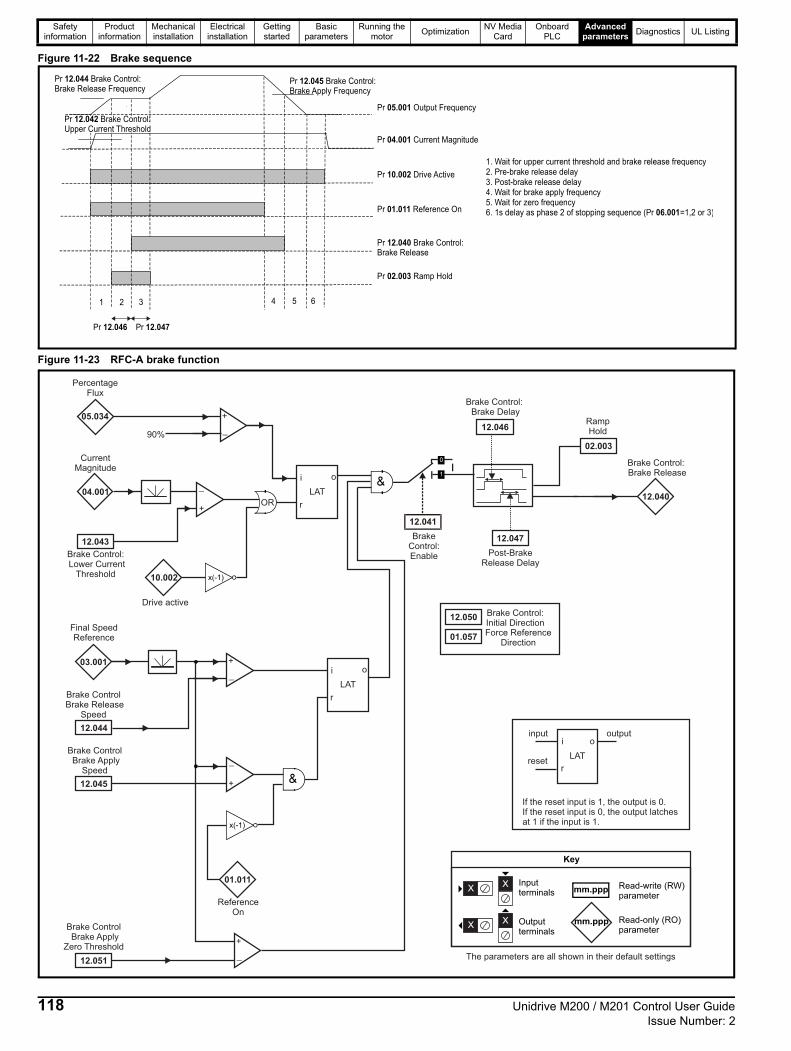
Safety information
Product information
Mechanical installation
Electrical installation
Getting started
Basic parameters
Running the motor
OptimizationNV Media
CardOnboard
PLCAdvanced
parametersDiagnostics UL Listing
Figure 11-22 Brake sequence
Figure 11-23 RFC-A brake function
1 2 3 4 65
Pr Output Frequency05.001
Pr Reference On01.011
Pr Brake Control:Brake Release
12.040
Pr Ramp Hold02.003
Pr Drive Active10.002
Pr Current Magnitude04.001
1. Wait for upper current threshold and brake release frequency2. Pre-brake release delay3. Post-brake release delay4. Wait for brake apply frequency5. Wait for zero frequency6. 1s delay as phase 2 of stopping sequence (Pr =1,2 or 3)06.001
Pr Brake Control:Brake Release Frequency
12.044 Pr Brake Control:Brake Apply Frequency
12.045
Pr 12.046 Pr 12.047
Pr Brake Control:Upper Current Threshold
12.042
04.001
CurrentMagnitude
Brake Control:Lower Current
Threshold
12.043
03.001
Final SpeedReference
Brake ControlBrake Release
Speed
12.044
+
_
LAT
input
reset
output
If the reset input is 1, the output is 0.If the reset input is 0, the output latchesat 1 if the input is 1.
i
r
o
+
_
LAT
i o
r
10.002
Drive active
05.034
PercentageFlux
90%
OR+
_
x(-1)
Post-BrakeRelease Delay
12.047
02.003
RampHold
12.040
Brake Control:Brake Release
12.046
Brake Control:Brake Delay
Brake ControlBrake Apply
Speed
12.045
LAT
i o
r
+
_
01.011
x(-1)
+
_
Brake ControlBrake Apply
Zero Threshold
12.051
12.041
BrakeControl:Enable
ReferenceOn
mm.ppp
mm.ppp
Key
Read-write (RW)parameter
Read-only (RO)parameter
Inputterminals
Outputterminals
XX
XX
The parameters are all shown in their default settings
12.050Brake Control:Initial DirectionForce Reference
Direction01 57.0
118 Unidrive M200 / M201 Control User Guide Issue Number: 2

Safety information
Product information
Mechanical installation
Electrical installation
Getting started
Basic parameters
Running the motor
OptimizationNV Media
CardOnboard
PLCAdvanced
parametersDiagnostics UL Listing
ParameterRange() Default()
TypeOL RFC-A OL RFC-A
12.001 Threshold Detector 1 Output Off (0) or On (1) RO Bit ND NC PT
12.002 Threshold Detector 2 Output Off (0) or On (1) RO Bit ND NC PT
12.003 Threshold Detector 1 Source 0.000 to 30.999 0.000 RW Num PT US
12.004 Threshold Detector 1 Level 0.00 to 100.00 % 0.00 % RW Num US
12.005 Threshold Detector 1 Hysteresis 0.00 to 25.00 % 0.00 % RW Num US
12.006 Threshold Detector 1 Output Invert Off (0) or On (1) Off (0) RW Bit US
12.007 Threshold Detector 1 Destination 0.000 to 30.999 0.000 RW Num DE PT US
12.008 Variable Selector 1 Source 1 0.000 to 30.999 0.000 RW Num PT US
12.009 Variable Selector 1 Source 2 0.000 to 30.999 0.000 RW Num PT US
12.010 Variable Selector 1 Mode0 (0), 1 (1), 2 (2), 3 (3), 4 (4), 5 (5),
6 (6), 7 (7), 8 (8), 9 (9)0 (0) RW Txt US
12.011 Variable Selector 1 Destination 0.000 to 30.999 0.000 RW Num DE PT US
12.012 Variable Selector 1 Output ± 100.00 % RO Num ND NC PT
12.013 Variable Selector 1 Source 1 Scaling ± 4.000 1.000 RW Num US
12.014 Variable Selector 1 Source 2 Scaling ± 4.000 1.000 RW Num US
12.015 Variable Selector 1 Control 0.00 to 100.00 0.00 RW Num US
12.016 Variable Selector 1 Enable Off (0) or On (1) On (1) RW Bit US
12.023 Threshold Detector 2 Source 0.000 to 30.999 0.000 RW Num PT US
12.024 Threshold Detector 2 Level 0.00 to 100.00 % 0.00 % RW Num US
12.025 Threshold Detector 2 Hysteresis 0.00 to 25.00 % 0.00 % RW Num US
12.026 Threshold Detector 2 Output Invert Off (0) or On (1) Off (0) RW Bit US
12.027 Threshold Detector 2 Destination 0.000 to 30.999 0.000 RW Num DE PT US
12.028 Variable Selector 2 Source 1 0.000 to 30.999 0.000 RW Num PT US
12.029 Variable Selector 2 Source 2 0.000 to 30.999 0.000 RW Num PT US
12.030 Variable Selector 2 Mode0 (0), 1 (1), 2 (2), 3 (3), 4 (4), 5 (5), 6 (6), 7 (7), 8 (8), 9 (9)
0 (0) RW Txt US
12.031 Variable Selector 2 Destination 0.000 to 30.999 0.000 RW Num DE PT US
12.032 Variable Selector 2 Output ± 100.00 % RO Num ND NC PT
12.033 Variable Selector 2 Source 1 Scaling ± 4.000 1.000 RW Num US
12.034 Variable Selector 2 Source 2 Scaling ± 4.000 1.000 RW Num US
12.035 Variable Selector 2 Control 0.00 to 100.00 0.00 RW Num US
12.036 Variable Selector 2 Enable Off (0) or On (1) On (1) RW Bit US
12.040 BC Brake Release Off (0) or On (1) RO Bit ND NC PT
12.041 BC Enable diS (0), rELAy (1), dig IO (2), USEr (3) diS (0) RW Txt US
12.042 BC Upper Current Threshold 0 to 200 % 50 % RW Num US
12.043 BC Lower Current Threshold 0 to 200 % 10 % RW Num US
12.044 BC Brake Release Frequency 0.00 to 20.00 Hz 1.00 Hz RW Num US
12.045 BC Brake Apply Frequency 0.00 to 20.00 Hz 2.00 Hz RW Num US
12.046 BC Brake Delay 0.0 to 25.0 s 1.0 s RW Num US
12.047 BC Post-brake Release Delay 0.0 to 25.0 s 1.0 s RW Num US
12.050 BC Initial Direction rEf (0), For (1), rEv (2) rEf (0) RW Txt US
12.051 BC Brake Apply Through Zero Threshold 0.00 to 25.00 Hz 1.00 Hz RW Num US
RW Read / Write RO Read only Num Number parameter Bit Bit parameter Txt Text string Bin Binary parameter FI Filtered
ND No default value NC Not copied PT Protected parameter RA Rating dependent US User save PS Power-down save DE Destination
Unidrive M200 / M201 Control User Guide 119Issue Number: 2

Safety information
Product information
Mechanical installation
Electrical installation
Getting started
Basic parameters
Running the motor
OptimizationNV Media
CardOnboard
PLCAdvanced
parametersDiagnostics UL Listing
11.14 Menu 14: User PID controllerFigure 11-24 Menu 14 Logic diagram
14.019
14.002
Any variableparameter
PID1 Feed-forwardsReference Source
PID1 Feed-forwardsReference
14.009
PID1 EnableSource 1
Sourcenot used
14.008
??.???
Any bitparameter
0
1
Logic 1
14.021
PID1Feedback
0
1x(-1)
14.006
PID1 FeedbackInvert
14.003
Any variableparameter
PID1 ReferenceSource
14.025
+
+
14.005 PID1 ReferenceInvert
14.020 0
114.007
+
_
14.022
x(-1) PID1 ReferenceSlew-Rate
PID1 Error
14.023
PID1 Reference Scaling
14.027
PID1 EnableSource 2
Sourcenot used
Any bitparameter
0
1
Logic 1??.???
??.???
??.???
PID1 Enable
14.004
Any variableparameter
PID1 FeedbackSource
+
+14.024
PID1 Feedback Scaling
14.026PID1 DigitalFeedback
PID1 DigitalReference
PID1Reference
??.???
??.???
??.???
??.???
??.???
??.???
120 Unidrive M200 / M201 Control User Guide Issue Number: 2
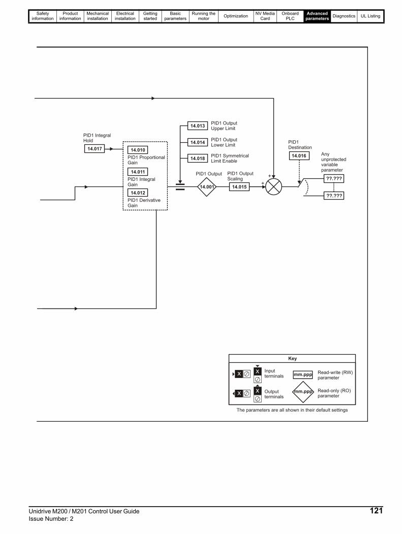
Safety information
Product information
Mechanical installation
Electrical installation
Getting started
Basic parameters
Running the motor
OptimizationNV Media
CardOnboard
PLCAdvanced
parametersDiagnostics UL Listing
14.010
14.011
14.012
14.017
14.013
14.014
14.018
14.001 14.015+
+
14.016
??.???
Anyunprotectedvariableparameter
PID1 DerivativeGain
PID1 IntegralGain
PID1 ProportionalGain
PID1 IntegralHold
PID1 OutputUpper Limit
PID1 OutputLower Limit
PID1 SymmetricalLimit Enable
PID1 Output PID1 OutputScaling
PID1Destination
??.???
mm.ppp
mm.ppp
Key
Read-write (RW)parameter
Read-only (RO)parameter
Inputterminals
Outputterminals
XX
XX
The parameters are all shown in their default settings
Unidrive M200 / M201 Control User Guide 121Issue Number: 2

Safety information
Product information
Mechanical installation
Electrical installation
Getting started
Basic parameters
Running the motor
OptimizationNV Media
CardOnboard
PLCAdvanced
parametersDiagnostics UL Listing
ParameterRange () Default ()
TypeOL RFC-A OL RFC-A
14.001 PID1 Output ± 100.00 % RO Num ND NC PT
14.002 PID1 Feed-forwards Reference Source 0.000 to 30.999 0.000 RW Num PT US
14.003 PID1 Reference Source 0.000 to 30.999 0.000 RW Num PT US
14.004 PID1 Feedback Source 0.000 to 30.999 0.000 RW Num PT US
14.005 PID1 Reference Invert Off (0) or On (1) Off (0) RW Bit US
14.006 PID1 Feedback Invert Off (0) or On (1) Off (0) RW Bit US
14.007 PID1 Reference Slew Rate 0.0 to 3200.0 s 0.0 s RW Num US
14.008 PID1 Enable Off (0) or On (1) Off (0) RW Bit US
14.009 PID1 Enable Source 1 0.000 to 30.999 0.000 RW Num PT US
14.010 PID1 Proportional Gain 0.000 to 4.000 1.000 RW Num US
14.011 PID1 Integral Gain 0.000 to 4.000 0.500 RW Num US
14.012 PID1 Differential Gain 0.000 to 4.000 0.000 RW Num US
14.013 PID1 Output Upper Limit 0.00 to 100.00 % 100.00 % RW Num US
14.014 PID1 Output Lower Limit ± 100.00 % -100.00 % RW Num US
14.015 PID1 Output Scaling 0.000 to 4.000 1.000 RW Num US
14.016 PID1 Destination 0.000 to 30.999 0.000 RW Num DE PT US
14.017 PID1 Integral Hold Off (0) or On (1) Off (0) RW Bit
14.018 PID1 Symmetrical Limit Enable Off (0) or On (1) Off (0) RW Bit US
14.019 PID1 Feed-forwards Reference ± 100.00 % RO Num ND NC PT
14.020 PID1 Reference ± 100.00 % RO Num ND NC PT
14.021 PID1 Feedback ± 100.00 % RO Num ND NC PT
14.022 PID1 Error ± 100.00 % RO Num ND NC PT
14.023 PID1 Reference Scaling 0.000 to 4.000 1.000 RW Num US
14.024 PID1 Feedback Scaling 0.000 to 4.000 1.000 RW Num US
14.025 PID1 Digital Reference ± 100.00 % 0.00 % RW Num US
14.026 PID1 Digital Feedback ± 100.00 % 0.00 % RW Num US
14.027 PID1 Enable Source 2 0.000 to 30.999 0.000 RW Num PT US
RW Read / Write RO Read only Num Number parameter Bit Bit parameter Txt Text string Bin Binary parameter FI Filtered
ND No default value NC Not copied PT Protected parameter RA Rating dependent US User save PS Power-down save DE Destination
122 Unidrive M200 / M201 Control User Guide Issue Number: 2

Safety information
Product information
Mechanical installation
Electrical installation
Getting started
Basic parameters
Running the motor
OptimizationNV Media
CardOnboard
PLCAdvanced
parametersDiagnostics UL Listing
Figure 11-25 Location of option module slot and its corresponding menu number
1. Option Module Slot 1 - Menu 15
11.15.1 Parameters common to all categories
The option module ID indicates the type of module that is installed in the corresponding slot. See the relevant option module user guide for more information regarding the module.
Parameter Range() Default() Type
15.001 Module ID 0 to 65535 RO Num ND NC PT15.002 Software Version 00.00.00 to 99.99.99 RO Ver ND NC PT15.003 Hardware Version 0.00 to 99.99 RO Num ND NC PT15.004 Serial Number LS
0 to 999999RO Num ND NC PT
15.005 Serial Number MS RO Num ND NC PT15.006 Module Status -2 to 3 RO Txt ND NC PT15.007 Module Reset Off (0) or On (1) Off (0) RW Bit NC
11.15 Menu 15: Option module set-up
1
Option module ID Module Category
0 No module installed
209 SI-I/O Automation (I/O Expansion)
431 SI-EtherCAT
Fieldbus
433 SI-Ethernet
434 SI-PROFINET V2
443 SI-PROFIBUS
447 SI-DeviceNet
448 SI-CANopen
Unidrive M200 / M201 Control User Guide 123Issue Number: 2

Safety information
Product information
Mechanical installation
Electrical installation
Getting started
Basic parameters
Running the motor
OptimizationNV Media
CardOnboard
PLCAdvanced
parametersDiagnostics UL Listing
11.16 Menu 18: Application menu 1
ParameterRange () Default()
TypeOL RFC-A OL RFC-A
18.001 Application Menu 1 Power-down Save Integer
-32768 to 32767
0 RW Num PS
18.002 Application Menu 1 Read-only Integer 2 RO Num ND NC
18.003 Application Menu 1 Read-only Integer 3 RO Num ND NC
18.004 Application Menu 1 Read-only Integer 4 RO Num ND NC
18.005 Application Menu 1 Read-only Integer 5 RO Num ND NC
18.006 Application Menu 1 Read-only Integer 6 RO Num ND NC
18.007 Application Menu 1 Read-only Integer 7 RO Num ND NC
18.008 Application Menu 1 Read-only Integer 8 RO Num ND NC
18.009 Application Menu 1 Read-only Integer 9 RO Num ND NC
18.010 Application Menu 1 Read-only Integer 10 RO Num ND NC
18.011 Application Menu 1 Read-write Integer 11
0
RW Num US
18.012 Application Menu 1 Read-write Integer 12 RW Num US
18.013 Application Menu 1 Read-write Integer 13 RW Num US
18.014 Application Menu 1 Read-write Integer 14 RW Num US
18.015 Application Menu 1 Read-write Integer 15 RW Num US
18.016 Application Menu 1 Read-write Integer 16 RW Num US
18.017 Application Menu 1 Read-write Integer 17 RW Num US
18.018 Application Menu 1 Read-write Integer 18 RW Num US
18.019 Application Menu 1 Read-write Integer 19 RW Num US
18.020 Application Menu 1 Read-write Integer 20 RW Num US
18.021 Application Menu 1 Read-write Integer 21 RW Num US
18.022 Application Menu 1 Read-write Integer 22 RW Num US
18.023 Application Menu 1 Read-write Integer 23 RW Num US
18.024 Application Menu 1 Read-write Integer 24 RW Num US
18.025 Application Menu 1 Read-write Integer 25 RW Num US
18.026 Application Menu 1 Read-write Integer 26 RW Num US
18.027 Application Menu 1 Read-write Integer 27 RW Num US
18.028 Application Menu 1 Read-write Integer 28 RW Num US
18.029 Application Menu 1 Read-write Integer 29 RW Num US
18.030 Application Menu 1 Read-write Integer 30 RW Num US
18.031 Application Menu 1 Read-write bit 31
Off (0) or On (1) Off (0)
RW Bit US
18.032 Application Menu 1 Read-write bit 32 RW Bit US
18.033 Application Menu 1 Read-write bit 33 RW Bit US
18.034 Application Menu 1 Read-write bit 34 RW Bit US
18.035 Application Menu 1 Read-write bit 35 RW Bit US
18.036 Application Menu 1 Read-write bit 36 RW Bit US
18.037 Application Menu 1 Read-write bit 37 RW Bit US
18.038 Application Menu 1 Read-write bit 38 RW Bit US
18.039 Application Menu 1 Read-write bit 39 RW Bit US
18.040 Application Menu 1 Read-write bit 40 RW Bit US
18.041 Application Menu 1 Read-write bit 41 RW Bit US
18.042 Application Menu 1 Read-write bit 42 RW Bit US
18.043 Application Menu 1 Read-write bit 43 RW Bit US
18.044 Application Menu 1 Read-write bit 44 RW Bit US
18.045 Application Menu 1 Read-write bit 45 RW Bit US
18.046 Application Menu 1 Read-write bit 46 RW Bit US
18.047 Application Menu 1 Read-write bit 47 RW Bit US
18.048 Application Menu 1 Read-write bit 48 RW Bit US
18.049 Application Menu 1 Read-write bit 49 RW Bit US
18.050 Application Menu 1 Read-write bit 50 RW Bit US
RW Read / Write RO Read only Num Number parameter Bit Bit parameter Txt Text string Bin Binary parameter FI Filtered
ND No default value NC Not copied PT Protected parameter RA Rating dependent US User save PS Power-down save DE Destination
124 Unidrive M200 / M201 Control User Guide Issue Number: 2

Safety information
Product information
Mechanical installation
Electrical installation
Getting started
Basic parameters
Running the motor
OptimizationNV Media
CardOnboard
PLCAdvanced
parametersDiagnostics UL Listing
11.17 Menu 20: Application menu 2
ParameterRange () Default ()
TypeOL RFC-A OL RFC-A
20.021 Application Menu 2 Read-write Long Integer 21
-2147483648 to 2147483647 0
RW Num
20.022 Application Menu 2 Read-write Long Integer 22 RW Num
20.023 Application Menu 2 Read-write Long Integer 23 RW Num
20.024 Application Menu 2 Read write Long Integer 24 RW Num
20.025 Application Menu 2 Read-write Long Integer 25 RW Num
20.026 Application Menu 2 Read-write Long Integer 26 RW Num
20.027 Application Menu 2 Read-write Long Integer 27 RW Num
20.028 Application Menu 2 Read-write Long Integer 28 RW Num
20.029 Application Menu 2 Read-write Long Integer 29 RW Num
20.030 Application Menu 2 Read-write Long Integer 30 RW Num
RW Read / Write RO Read only Num Number parameter Bit Bit parameter Txt Text string Bin Binary parameter FI Filtered
ND No default value NC Not copied PT Protected parameter RA Rating dependent US User save PS Power-down save DE Destination
Unidrive M200 / M201 Control User Guide 125Issue Number: 2

Safety information
Product information
Mechanical installation
Electrical installation
Getting started
Basic parameters
Running the motor
OptimizationNV Media
CardOnboard
PLCAdvanced
parametersDiagnostics UL Listing
11.18 Menu 21: Second motor parameters
* When read via serial communications, this parameter will show pole pairs.
** For size 9, the default is 141.9 %.
*** For size 9, the default is 150.0 %.
ParameterRange () Default ()
TypeOL RFC-A OL RFC-A
21.001 M2 Maximum Speed 0.00 to 550.00 Hz50Hz: 50.00 Hz60Hz: 60.00 Hz
RW Num US
21.002 M2 Minimum Speed 0.00 to Pr 21.001 Hz 0.00 RW Num US
21.003 M2 Reference SelectorA1.A2 (0), A1.Pr (1), A2.Pr (2), PrESEt (3),
PAd (4), rES (5), PAd.rEF (6)A1.A2 (0) RW Txt US
21.004 M2 Acceleration Rate 1 0.0 to 32000.0 s/100 Hz 5.0 s/100 Hz RW Num US
21.005 M2 Deceleration Rate 1 0.0 to 32000.0 s/100 Hz 10.0 s/100 Hz RW Num US
21.006 M2 Motor Rated Frequency 0.00 to 550.00 Hz50Hz: 50.00 Hz60Hz: 60.00 Hz
RW Num RA US
21.007 M2 Motor Rated Current 0.00 to Drive Rating A Maximum Heavy Duty Rating (11.032) RW Num RA US
21.008 M2 Motor Rated Speed 0.0 to 33000.0 rpm50 Hz: 1500.0 rpm60 Hz: 1800.0 rpm
50 Hz: 1450.0 rpm
60 Hz 1750.0 rpm
RW Num US
21.009 M2 Motor Rated Voltage 0 to 765 V
110 V drive: 230 V200 V drive: 230 V
400 V drive 50Hz: 400 V400 V drive 60Hz: 460 V
575 V drive: 575 V690 V drive: 690 V
RW Num RA US
21.010 M2 Motor Rated Power Factor 0.00 to 1.00 0.85 RW Num RA US
21.011 M2 Number of Motor Poles* Auto (0) to 32 (16) Auto (0) RW Num US
21.012 M2 Stator Resistance 0.0000 to 99.9999 Ω 0.0000 Ω RW Num RA US
21.014 M2 Transient Inductance 0.000 to 500.000 mH 0.000 mH RW Num RA US
21.015 Motor 2 Active Off (0) or On (1) RO Bit ND NC PT
21.016 M2 Motor Thermal Time Constant 1 1 to 3000 s 179 s 179 s RW Num US
21.017M2 Frequency ControllerProportional Gain Kp1
0.000 to 200.000 s/rad
0.100 s/rad RW Num US
21.018M2 Frequency Controller IntegralGain Ki1
0.00 to 655.35s²/rad
0.10 s²/rad RW Num US
21.019M2 Frequency ControllerDifferential Feedback Gain Kd1
0.00000 to0.65535 1/rad
0.00000 1/rad RW Num US
21.022 M2 Current Controller Kp Gain 0.00 to 4000.00 20.00 RW Num US
21.023 M2 Current Controller Ki Gain 0.000 to 600.000 40.000 RW Num US
21.024 M2 Stator Inductance 0.00 to 5000.00 mH 0.00 mH RW Num RA US
21.025 M2 Saturation Breakpoint 1 0.0 to 100.0 % 50.0 % RW Num US
21.026 M2 Saturation Breakpoint 3 0.0 to 100.0 % 75.0 % RW Num US
21.027 M2 Motoring Current Limit 0.0 to VM_MOTOR2_CURRENT_LIMIT % 165.0 %** 175.0 %*** RW Num RA US
21.028 M2 Regenerating Current Limit 0.0 to VM_MOTOR2_CURRENT_LIMIT % 165.0 %** 175.0 %*** RW Num RA US
21.029 M2 Symmetrical Current Limit 0.0 to VM_MOTOR2_CURRENT_LIMIT % 165.0 %** 175.0 %*** RW Num RA US
21.033M2 Low Frequency ThermalProtection Mode
0 to 1 0 RW Num US
21.041 M2 Saturation Breakpoint 2 0.0 to 100.0 % 0.0 % RW Num US
21.042 M2 Saturation Breakpoint 4 0.0 to 100.0 % 0.0 % RW Num US
RW Read / Write RO Read only Num Number parameter Bit Bit parameter Txt Text string Bin Binary parameter FI Filtered
ND No default value NC Not copied PT Protected parameter RA Rating dependent US User save PS Power-down save DE Destination
126 Unidrive M200 / M201 Control User Guide Issue Number: 2

Safety information
Product information
Mechanical installation
Electrical installation
Getting started
Basic parameters
Running the motor
OptimizationNV Media
CardOnboard
PLCAdvanced
parametersDiagnostics UL Listing
11.19 Menu 22: Additional Menu 0 set-up
ParameterRange() Default()
TypeOL RFC-A OL RFC-A
22.011 Parameter 00.011 Set-up 0.000 to 30.999 6.004 RW Num PT US
22.012 Parameter 00.012 Set-up 0.000 to 30.999 0.000 RW Num PT US
22.013 Parameter 00.013 Set-up 0.000 to 30.999 0.000 RW Num PT US
22.014 Parameter 00.014 Set-up 0.000 to 30.999 0.000 RW Num PT US
22.015 Parameter 00.015 Set-up 0.000 to 30.999 1.005 RW Num PT US
22.016 Parameter 00.016 Set-up 0.000 to 30.999 7.007 RW Num PT US
22.017 Parameter 00.017 Set-up 0.000 to 30.999 1.010 RW Num PT US
22.018 Parameter 00.018 Set-up 0.000 to 30.999 1.021 RW Num PT US
22.019 Parameter 00.019 Set-up 0.000 to 30.999 1.022 RW Num PT US
22.020 Parameter 00.020 Set-up 0.000 to 30.999 1.023 RW Num PT US
22.021 Parameter 00.021 Set-up 0.000 to 30.999 1.024 RW Num PT US
22.022 Parameter 00.022 Set-up 0.000 to 30.999 11.019 RW Num PT US
22.023 Parameter 00.023 Set-up 0.000 to 30.999 11.018 RW Num PT US
22.024 Parameter 00.024 Set-up 0.000 to 30.999 11.021 RW Num PT US
22.025 Parameter 00.025 Set-up 0.000 to 30.999 11.030 RW Num PT US
22.026 Parameter 00.026 Set-up 0.000 to 30.999 0.000 RW Num PT US
22.027 Parameter 00.027 Set-up 0.000 to 30.999 1.051 RW Num PT US
22.028 Parameter 00.028 Set-up 0.000 to 30.999 2.004 RW Num PT US
22.029 Parameter 00.029 Set-up 0.000 to 30.999 0.000 2.002 RW Num PT US
22.030 Parameter 00.030 Set-up 0.000 to 30.999 11.042 RW Num PT US
22.031 Parameter 00.031 Set-up 0.000 to 30.999 6.001 RW Num PT US
22.032 Parameter 00.032 Set-up 0.000 to 30.999 5.013 RW Num PT US
22.033 Parameter 00.033 Set-up 0.000 to 30.999 6.009 RW Num PT US
22.034 Parameter 00.034 Set-up 0.000 to 30.999 8.035 RW Num PT US
22.035 Parameter 00.035 Set-up 0.000 to 30.999 8.091 RW Num PT US
22.036 Parameter 00.036 Set-up 0.000 to 30.999 7.055 RW Num PT US
22.037 Parameter 00.037 Set-up 0.000 to 30.999 5.018 RW Num PT US
22.038 Parameter 00.038 Set-up 0.000 to 30.999 5.012 RW Num PT US
22.039 Parameter 00.039 Set-up 0.000 to 30.999 5.006 RW Num PT US
22.040 Parameter 00.040 Set-up 0.000 to 30.999 5.011 RW Num PT US
22.041 Parameter 00.041 Set-up 0.000 to 30.999 5.014 RW Num PT US
22.042 Parameter 00.042 Set-up 0.000 to 30.999 5.015 RW Num PT US
22.043 Parameter 00.043 Set-up 0.000 to 30.999 11.025 RW Num PT US
22.044 Parameter 00.044 Set-up 0.000 to 30.999 11.023 RW Num PT US
22.045 Parameter 00.045 Set-up 0.000 to 30.999 11.020 RW Num PT US
22.046 Parameter 00.046 Set-up 0.000 to 30.999 12.042 RW Num PT US
22.047 Parameter 00.047 Set-up 0.000 to 30.999 12.043 RW Num PT US
22.048 Parameter 00.048 Set-up 0.000 to 30.999 12.044 RW Num PT US
22.049 Parameter 00.049 Set-up 0.000 to 30.999 12.045 RW Num PT US
22.050 Parameter 00.050 Set-up 0.000 to 30.999 12.046 RW Num PT US
22.051 Parameter 00.051 Set-up 0.000 to 30.999 12.047 RW Num PT US
22.052 Parameter 00.052 Set-up 0.000 to 30.999 0.000 RW Num PT US
22.053 Parameter 00.053 Set-up 0.000 to 30.999 12.050 RW Num PT US
22.054 Parameter 00.054 Set-up 0.000 to 30.999 12.051 RW Num PT US
22.055 Parameter 00.055 Set-up 0.000 to 30.999 12.041 RW Num PT US
22.056 Parameter 00.056 Set-up 0.000 to 30.999 10.020 RW Num PT US
22.057 Parameter 00.057 Set-up 0.000 to 30.999 10.021 RW Num PT US
22.058 Parameter 00.058 Set-up 0.000 to 30.999 10.022 RW Num PT US
22.059 Parameter 00.059 Set-up 0.000 to 30.999 11.047 RW Num PT US
22.060 Parameter 00.060 Set-up 0.000 to 30.999 11.048 RW Num PT US
22.061 Parameter 00.061 Set-up 0.000 to 30.999 0.000 RW Num PT US
22.062 Parameter 00.062 Set-up 0.000 to 30.999 0.000 RW Num PT US
22.063 Parameter 00.063 Set-up 0.000 to 30.999 0.000 RW Num PT US
22.064 Parameter 00.064 Set-up 0.000 to 30.999 0.000 RW Num PT US
22.065 Parameter 00.065 Set-up 0.000 to 30.999 0.000 3.010 RW Num PT US
22.066 Parameter 00.066 Set-up 0.000 to 30.999 0.000 3.011 RW Num PT US
22.067 Parameter 00.067 Set-up 0.000 to 30.999 0.000 3.079 RW Num PT US
Unidrive M200 / M201 Control User Guide 127Issue Number: 2

Safety information
Product information
Mechanical installation
Electrical installation
Getting started
Basic parameters
Running the motor
OptimizationNV Media
CardOnboard
PLCAdvanced
parametersDiagnostics UL Listing
11.20 Menu 24: Option Module Application
22.068 Parameter 00.068 Set-up 0.000 to 30.999 0.000 0.000 RW Num PT US
22.069 Parameter 00.069 Set-up 0.000 to 30.999 5.040 RW Num PT US
22.070 Parameter 00.070 Set-up 0.000 to 30.999 14.001 RW Num PT US
22.071 Parameter 00.071 Set-up 0.000 to 30.999 14.010 RW Num PT US
22.072 Parameter 00.072 Set-up 0.000 to 30.999 14.011 RW Num PT US
22.073 Parameter 00.073 Set-up 0.000 to 30.999 14.006 RW Num PT US
22.074 Parameter 00.074 Set-up 0.000 to 30.999 14.013 RW Num PT US
22.075 Parameter 00.075 Set-up 0.000 to 30.999 14.014 RW Num PT US
22.076 Parameter 00.076 Set-up 0.000 to 30.999 10.037 RW Num PT US
22.077 Parameter 00.077 Set-up 0.000 to 30.999 11.032 RW Num PT US
22.078 Parameter 00.078 Set-up 0.000 to 30.999 11.029 RW Num PT US
22.079 Parameter 00.079 Set-up 0.000 to 30.999 11.031 RW Num PT US
22.080 Parameter 00.080 Set-up 0.000 to 30.999 0.000 RW Num PT US
ParameterRange() Default()
TypeOL RFC-A OL RFC-A
RW Read / Write RO Read only Num Number parameter Bit Bit parameter Txt Text string Bin Binary parameter FI Filtered
ND No default value NC Not copied PT Protected parameter RA Rating dependent US User save PS Power-down save DE Destination
128 Unidrive M200 / M201 Control User Guide Issue Number: 2

Safety information
Product information
Mechanical installation
Electrical installation
Getting started
Basic parameters
Running the motor
OptimizationNV Media
CardOnboard
PLCAdvanced
parameters Diagnostics UL Listing
12 DiagnosticsThe keypad display on the drive gives various information about the status of the drive. The keypad display provides information on the following categories:
• Trip indications • Alarm indications • Status indications
12.1 Status modes (Keypad and LED status)Figure 12-1 Keypad status modes
1 Drive OK status
2 Trip status
3 Alarm status
12.2 Trip indicationsThe output of the drive is disabled under any trip condition so that the drive stops controlling the motor. If the motor is running when the trip occurs it will coast to a stop.
During a trip condition, the display indicates that a trip has occurred and the keypad will display the trip string. Some trips have a sub-trip number to provide additional information about the trip. If a trip has a sub-trip number, the sub-trip number is flashed alternately with the trip string.
Trips are listed alphabetically in Table 12-2 based on the trip indication shown on the drive display. Alternatively, the drive status can be read in Pr 10.001 'Drive OK' using communication protocols. The most recent trip can be read in Pr 10.020 providing a trip number. It must be noted that the hardware trips (HF01 to HF23) do not have trip numbers. The trip number must be checked in Table 12-2 to identify the specific trip.
Example1. Trip code 2 is read from Pr 10.020 via serial communications.2. Checking Table 12-3 shows Trip 2 is an OV trip.
3. Look up OV in Table 12-2.4. Perform checks detailed under Diagnosis.
12.3 Identifying a trip / trip sourceSome trips only contain a trip string whereas some other trips have a trip string along with a sub-trip number which provides the user with additional information about the trip.
A trip can be generated from a control system or from a power system. The sub-trip number associated with the trips listed in Table 12-1 is in the form xxyzz and used to identify the source of the trip.
Table 12-1 Trips associated with xxyzz sub-trip number
The digits xx are 00 for a trip generated by the control system. For a drive, if the trip is related to the power system then xx will have a value of 01, when displayed the leading zeros are suppressed.
For a control system trip (xx is zero), the y digit where relevant is defined for each trip. If not relevant, the y digit will have a value of zero.
The zz digits give the reason for the trip and are defined in each trip description.
Figure 12-2 Key to sub-trip number
Users must not attempt to repair a drive if it is faulty, nor carry out fault diagnosis other than through the use of the diagnostic features described in this chapter.If a drive is faulty, it must be returned to an authorized Control Techniques distributor for repair.WARNING
1
3
2
OV PH.Lo
PSU OI.Sn
Oht.I tH.Fb
Oht.P P.dAt
Oh.dc
Keypaddisplay
Commscode
No. Trip
2 OV
x x y z z
00 - Generated by the control module
01 - Generated by the power module
0 Upwards - Identifies the location of the trip
00
01
.
.
07
- Reason for the trip
Unidrive M200 / M201 Control User Guide 129Issue Number: 2

Safety information
Product information
Mechanical installation
Electrical installation
Getting started
Basic parameters
Running the motor
OptimizationNV Media
CardOnboard
PLCAdvanced
parameters Diagnostics UL Listing
12.4 Trips, Sub-trip numbersTable 12-2 Trip indications
Trip Diagnosis
C.Acc NV Media Card Write fail
185
The C.Acc trip indicates that the drive was unable to access the NV Media Card. If the trip occurs during the data transfer to the card then the file being written may be corrupted. If the trip occurs when the data being transferred to the drive then the data transfer may be incomplete. If a parameter file is transferred to the drive and this trip occurs during the transfer, the parameters are not saved to non-volatile memory, and so the original parameters can be restored by powering the drive down and up again.
Recommended actions:
• Check NV Media Card is installed / located correctly• Replace the NV Media Card
C.by NV Media Card cannot be accessed as it is being accessed by an option module
178
The C.by trip indicates that an attempt has been made to access a file on NV Media Card, but the NV Media Card is already being accessed by an option module. No data is transferred.
Recommended actions:
• Wait for the option module to finish accessing the NV Media Card and re-attempt the required function
C.cPr NV Media Card file/data is different to the one in the drive
188
A compare has been carried out between a file on the NV Media Card and the drive, a C.cPr trip is initiated if the parameters on the NV Media Card are different to the drive.
Recommended actions:
• Set Pr 00 to 0 and reset the trip• Check to ensure the correct data block on the NV Media Card has been used for the compare
C.d.E NV Media Card data location already contains data
179
The C.d.E trip indicates that an attempt has been made to store data on a NV Media Card in a data block which already contains data.
Recommended actions:
• Erase the data in data location• Write data to an alternative data location
C.dAt NV Media Card data not found
183
The C.dAt trip indicates that an attempt has been made to access a non-existent file on the NV Media Card.
No data is transferred.
Recommended actions:
• Ensure data file number is correct
C.Err NV Media Card data structure error
182
The C.Err trip indicates that an attempt has been made to access the NV Media Card but an error has been detected in the data structure on the card. Resetting the trip will cause the drive to erase and create the correct folder structure. On an SD card, whilst this trip is present, missing directories will be created and if the header file is missing it will be created. The cause of the trip can be identified by the sub-trip.
Recommended actions:
• Erase all the data block and re-attempt the process• Ensure the card is located correctly• Replace the NV Media Card
C.FuL NV Media Card full
184
The C.FuL trip indicates that an attempt has been made to create a data block on a NV Media Card, but there is not enough space left on the card. No data is transferred.
Recommended actions:
• Delete a data block or the entire NV Media Card to create space• Use a different NV Media Card
Sub-trip Reason
1 The required folder and file structure is not present
2 The 000.DAT file is corrupted
3 Two or more files in the MCDF\ folder have the same file identification number
130 Unidrive M200 / M201 Control User Guide Issue Number: 2

Safety information
Product information
Mechanical installation
Electrical installation
Getting started
Basic parameters
Running the motor
OptimizationNV Media
CardOnboard
PLCAdvanced
parameters Diagnostics UL Listing
C.OPt NV Media Card trip; option module installed is different between source drive and destination drive
180
The C.OPt trip indicates that parameter data is being transferred from the NV Media Card to the drive, but the option module category is different between the source and destination drives. This trip does not stop the data transfer, but is a warning that the data for the option module that is different will be set to the default values and not the values from the card. This trip also applies if a compare is performed between the data block on the card and the drive, and the option module fitted is different between the source and target.
Recommended actions:
• Ensure the correct option module is installed. • Press the red reset button to acknowledge that the parameters for the option module installed will be at their
default values• This trip can be suppressed by setting Pr 00 to 9666 and resetting the drive.
C.Pr NV Media Card data blocks are not compatible with the drive derivative
175
The C.Pr trip is initiated either at power-up or when the card is accessed, If Drive Derivative (11.028) or Product Type (11.063) are different between the source and target drives. This trip can be reset and data can be transferred in either direction between the drive and the card.
Recommended actions:
• Use a different NV Media Card• This trip can be suppressed by setting Pr 00 to 9666 and resetting the drive• Choose a file compatible between the source and target drives, if sub-trip 2.
C.rdo NV Media Card has the Read Only bit set
181
The C.rdo trip indicates that an attempt has been made to modify data on a read-only NV Media Card or to modify a read-only data block. A NV Media Card is read-only if the read-only flag has been set.
Recommended actions:
• Clear the read only flag by setting Pr 00 to 9777 and reset the drive. This will clear the read-only flag for all data blocks in the NV Media Card
C.rtg NV Media Card Trip; The voltage and / or current rating of the source and destination drives are different
186
The C.rtg trip indicates that parameter data is being transferred from the NV Media Card to the drive, but the current and / or voltage ratings are different between source and destination drives. This trip also applies if a compare (using Pr 00 set to 8yyy) is performed between the data block on a NV Media Card and the drive. The C.rtg trip does not stop the data transfer but is a warning that rating specific parameters with the RA attribute may not be transferred to the destination drive.
Recommended actions:
• Reset the drive to clear the trip• Ensure that the drive rating dependent parameters have transferred correctly • This trip can be suppressed by setting Pr 00 to 9666 and resetting the drive.
C.SL NV Media Card trip; Option module file transfer has failed
174The C.SL trip is initiated, if the transfer of an option module file to or from a module failed because the option module does not respond correctly. If this happens this trip is produced with the sub-trip number indicating the option module slot number.
C.tyP NV Media Card parameter set not compatible with current drive mode
187
The C.tyP trip is produced during a compare if the drive mode in the data block on the NV Media Card is different from the current drive mode. This trip is also produced if an attempt is made to transfer parameters from a NV Media Card to the drive if the operating mode in the data block is outside the allowed range of operating modes, for the target drive.
Recommended actions:
• Ensure the destination drive supports the drive operating mode in the parameter file.• Clear the value in Pr 00 and reset the drive• Ensure destination drive operating mode is the same as the source parameter file
Trip Diagnosis
Sub-trip Reason
1If Drive Derivative (11.028) is different between the source and target drives. This trip is initiated either at power-up or when the SD card is accessed. This trip can be reset and data can be transferred in either direction between the drive and the card.
2If Product Type (11.063) is different between the source and target drives or the file is corrupted or incompatible. This trip is initiated either at power-up or when the SD card is accessed. This trip can be reset but no data are transferred in either direction between the drive and the card.
Unidrive M200 / M201 Control User Guide 131Issue Number: 2

Safety information
Product information
Mechanical installation
Electrical installation
Getting started
Basic parameters
Running the motor
OptimizationNV Media
CardOnboard
PLCAdvanced
parameters Diagnostics UL Listing
cL.A1 Analog input 1 current loss
28
The cL.A1 trip indicates that a current loss was detected in current mode on Analog input 1 (Terminal 2). In 4-20 mA and 20-4 mA modes loss of input is detected if the current falls below 3 mA.
Recommended actions:
• Check control wiring is correct• Check control wiring is undamaged• Check the Analog Input 1 Mode (07.007)• Current signal is present and greater than 3 mA
CL.bt Trip initiated from the Control Word (06.042)
35
The CL.bt trip is initiated by setting bit 12 on the control word in Pr 06.042 when the control word is enabled (Pr 06.043 = On).
Recommended actions:
• Check the value of Pr 06.042. • Disable the control word in Control Word Enable (06.043)
Bit 12 of the control word set to a one causes the drive to trip on Control WordWhen the control word is enabled, the trip can only be cleared by setting bit 12 to zero
Cur.c Current calibration range
231
Current calibration range error.
Recommended actions:
• Hardware fault - contact the supplier of the drive
Cur.O Current feedback offset error
225
The Cur.O trip indicates that the current offset is too large to be trimmed.
Recommended actions:
• Ensure that there is no possibility of current flowing in the output phases of the drive when the drive is not enabled • Hardware fault – contact the supplier of the drive
d.Ch Drive parameters are being changed
97
A user action or a file system write is active that is changing the drive parameters and the drive has been commanded to enable, i.e. Drive Active (10.002) = 1.
The user actions that change drive parameters are loading defaults, changing drive mode, or transferring data from an NV memory card to the drive. The file system actions that will cause this trip to be initiated if the drive is enabled during the transfer and is writing a parameter or macro file to the drive. It should be noted that none of these actions can be started if the drive is active, and so the trip only occurs if the action is started and then the drive is enabled.
Recommended actions:
• Ensure the drive is not enabled when one of the following is being carried out: Loading defaults
Changing drive mode
Transferring data from NV media card
dcct dcct reference out of range for size 5 upwards only
110
The sub-trip number indicates the DCCT that has caused the trip.
Recommended actions:
• Hardware fault - contact the supplier of the drive
dEr.E Derivative file error
246
Derivative file error with sub-trips:
Recommended actions:
• Contact the supplier of the drive.
Trip Diagnosis
Sub-trip Reason Comments
1 The derivative file is missing or is invalidOccurs when the drive powers-up. Load valid derivative file matching the control board hardware.
2The derivative file does not match the control board hardware
Occurs when the drive powers-up. Load valid derivative file matching the control board hardware.
3The derivative file has been changed for a file with a different derivative number.
Occurs when the drive powers-up or the file is programmed. The file tasks will not run.
132 Unidrive M200 / M201 Control User Guide Issue Number: 2

Safety information
Product information
Mechanical installation
Electrical installation
Getting started
Basic parameters
Running the motor
OptimizationNV Media
CardOnboard
PLCAdvanced
parameters Diagnostics UL Listing
dEr.I Derivative product image error
248
The dEr.I trip indicates that an error has been detected in the derivative product image. The reason for the trip can be identified by the sub-trip number.
dESt Two or more parameters are writing to the same destination parameter
199
The dest trip indicates that destination parameters of two or more functions (Menus 7, 8, 9, 12 or 14) within the drive are writing to the same parameter.
Recommended actions:
• Set Pr 00 to ‘dest’ or 12001 and check all visible parameters in all menus for parameter write conflicts
Trip Diagnosis
Recommended actions:
• Contact the supplier of the drive
Sub-trip Reason Comments
1 Divide by zero
2 Undefined trip
3Attempted fast parameter access set-up with non-existent parameter
4 Attempted access to non-existent parameter
5 Attempted write to read-only parameter
6 Attempted an over-range write
7 Attempted read from write-only parameter
30The image has failed because either its CRC is incorrect, or there are less than 6 bytes in the image or the image header version is less than 5
Occurs when the drive powers-up or the image is programmed. The image tasks will not run
31The image requires more RAM for heap and stack than can be provided by the drive.
As 30
32The image requires an OS function call that is higher than the maximum allowed.
As 30
33 The ID code within the image is not valid As 30
34The derivative image has been changed for an image with a different derivative number
As 30
40The timed task has not completed in time and has been suspended
Reduce code in timed task or power down repeat rate.
41Undefined function called, i.e. a function in the host system vector table that has not been assigned
As 40
51 Core menu customization table CRC check failed As 30
52 Customizable menu table CRC check failed As 30
53 Customizable menu table changed
Occurs when the drive powers-up or the image is programmed and the table has changed. Defaults are loaded for the derivative menu and the trip will keep occurring until drive parameters are saved.
61The option module installed in slot 1 is not allowed with the derivative image
As 30
80 Image is not compatible with the control board Initiated from within the image code
81 Image is not compatible with the control board serial number As 80
Unidrive M200 / M201 Control User Guide 133Issue Number: 2

Safety information
Product information
Mechanical installation
Electrical installation
Getting started
Basic parameters
Running the motor
OptimizationNV Media
CardOnboard
PLCAdvanced
parameters Diagnostics UL Listing
dr.CF Drive configuration
232
The hardware ID does not match the user software ID.
Recommended actions:
• Hardware fault – Contact the supplier of the drive
EEF Default parameters have been loaded
31
The EEF trip indicates that default parameters have been loaded. The exact cause/reason of the trip can be identified from the sub-trip number.
The drive holds two banks of user save parameters and two banks of power down save parameters in non-volatile memory. If the last bank of either set of parameters that was saved is corrupted a U.S or Pd.S trip is produced. If one of these trips occurs the parameters values that were last saved successfully are used. It can take some time to save parameters when requested by the user and if the power is removed from the drive during this process it is possible to corrupt the data in the non-volatile memory. If both banks of user save parameters or both banks of power down save parameters are corrupted or one of the other conditions given in the table above occurs EEF.xxx trip is produced. If this trip occurs it is not possible to use the data that has been saved previously, and so the drive will be loaded with default parameters. The trip can only be reset if Parameter mm.000 (mm.000) is set to 10, 11, 1233 or 1244 or if Load Defaults (11.043) is set to a non-zero value.
Recommended actions:
• Default the drive and perform a reset• Allow sufficient time to perform a save before the supply to the drive is removed• If the trip persists - return drive to supplier
Et An External trip is initiated
6
An Et trip has occurred. The cause of the trip can be identified from the sub trip number displayed after the trip string. See table below. An external trip can also be initiated by writing a value of 6 in Pr 10.038.
Recommended actions:
• Check the value of Pr 10.032. • Select ‘dest’ (or enter 12001) in Pr mm.000 and check for a parameter controlling Pr 10.032.• Ensure Pr 10.032 or Pr 10.038 (= 6) is not being controlled by serial comms
FAn.F Fan fail
173
This trip cannot be reset until 10s after the trip was initiated.
Recommended actions:
• Check that the fan is fitted and connected correctly.• Check that the fan is not obstructed.• Contact the supplier of the drive to replace the fan.
Fi.Ch File changed
247Recommended action:
• Power cycle the drive.
Trip Diagnosis
Sub-trip Reason
1 The hardware ID does not match the user software ID (size 5 upwards only).
2 Invalid hardware ID.
3 The hardware ID does not match the user software ID (Size 1-4)
Sub-trip Reason
1 The most significant digit of the internal parameter database version number has changed
2The CRC's applied to the parameter data stored in internal non-volatile memory indicate that a valid set of parameters cannot be loaded
3The drive mode restored from internal non-volatile memory is outside the allowed range for the product or the derivative image does not allow the previous drive mode
4 The drive derivative image has changed
5 The power stage hardware has changed
6 Reserved
7 Reserved
8 The control board hardware has changed
9 The checksum on the non-parameter area of the EEPROM has failed
Sub-trip Reason
3 External Trip (10.032) = 1
134 Unidrive M200 / M201 Control User Guide Issue Number: 2

Safety information
Product information
Mechanical installation
Electrical installation
Getting started
Basic parameters
Running the motor
OptimizationNV Media
CardOnboard
PLCAdvanced
parameters Diagnostics UL Listing
FI.In Firmware Incompatibility
237
The FI.In trip indicates that the user firmware is incompatible with the power firmware.
Recommended actions:
Re-program the drive with the latest version of the drive firmware for Unidrive M200, using Unidrive M Connect.
HF01 Data processing error: CPU hardware fault
The HF01 trip indicates that a CPU address error has occurred. This trip indicates that the control PCB on the drive has failed.
Recommended actions:
• Hardware fault – Contact the supplier of the drive
HF02 Data processing error: CPU memory management fault
The HF02 trip indicates that a DMAC address error has occurred. This trip indicates that the control PCB on the drive has failed.
Recommended actions:
• Hardware fault – Contact the supplier of the drive
HF03 Data processing error: CPU has detected a bus fault
The HF03 trip indicates that a bus fault has occurred. This trip indicates that the control PCB on the drive has failed.
Recommended actions:
• Hardware fault – Contact the supplier of the drive
HF04 Data processing error: CPU has detected a usage fault
The HF04 trip indicates that a usage fault has occurred.This trip indicates that the control PCB on the drive has failed.
Recommended actions:
• Hardware fault – Contact the supplier of the drive
HF05 Reserved
HF06 Reserved
HF07 Data processing error: Watchdog failure
The HF07 trip indicates that a watchdog failure has occurred. This trip indicates that the control PCB on the drive has failed.
Recommended actions:
• Hardware fault – Contact the supplier of the drive
HF08 Data processing error: CPU Interrupt crash
The HF08 trip indicates that a CPU interrupt crash has occurred. This trip indicates that the control PCB on the drive has failed. The crash level is indicated by the sub-trip number.
Recommended actions:
• Hardware fault – Contact the supplier of the drive
HF09 Data processing error: Free store overflow
The HF09 trip indicates that a free store overflow has occurred. This trip indicates that the control PCB on the drive has failed.
Recommended actions:
• Hardware fault – Contact the supplier of the drive
HF10 Reserved
HF11 Data processing error: Non-volatile memory comms error
The HF11 trip indicates that a non-volatile memory comms error has occurred. The crash level is indicated by the sub-trip number. This trip indicates that the control PCB on the drive has failed.
Trip Diagnosis
Sub-trip Reason Recommended action
1 Non-volatile memory comms error. Hardware fault - contact the supplier of the drive.
2 EEPROM size is incompatible with the user firmware. Re-program drive with compatible user firmware.
Unidrive M200 / M201 Control User Guide 135Issue Number: 2

Safety information
Product information
Mechanical installation
Electrical installation
Getting started
Basic parameters
Running the motor
OptimizationNV Media
CardOnboard
PLCAdvanced
parameters Diagnostics UL Listing
HF12 Data processing error: main program stack overflow
The HF12 trip indicates that the main program stack overflow has occurred. The stack can be identified by the sub-trip number. This trip indicates that the control PCB on the drive has failed.
Recommended actions:
Hardware fault - Contact the supplier of the drive.
HF13 Reserved
HF14 Reserved
HF15 Reserved
HF16 Data processing error: RTOS error
The HF16 trip indicates that a RTOS error has occurred. This trip indicates that the control PCB on the drive has failed.
Recommended actions:
• Hardware fault – Contact the supplier of the drive
HF17 Reserved
HF18 Data processing error: Internal flash memory has failed
The HF18 trip indicates that the internal flash memory has failed when writing option module parameter data. The reason for the trip can be identified by the sub-trip number.
Recommended actions:
• Hardware fault - Contact the supplier of the drive.
HF19 Data processing error: CRC check on the firmware has failed
The HF19 trip indicates that the CRC check on the drive firmware has failed. The drive is now in its bootloader mode and is waiting for a new image to be downloaded using Unidrive M Connect. Once a new image is downloaded, the drive can run normally.
Recommended actions:
• Re-program the drive, with latest control and power firmware using Unidrive M Connect.• Hardware fault - Contact the supplier of the drive.
HF23 Hardware fault
Recommended action:
• If this trip occurs - contact the supplier of the drive.
It.Ac Output current overload timed out (I2t)
20
The It.Ac trip indicates a motor thermal overload based on the Motor Rated Current (Pr 05.007) and Motor Thermal Time Constant (Pr 04.015). Pr 04.019 displays the motor temperature as a percentage of the maximum value. The drive will trip on It.Ac when Pr 04.019 gets to 100 %.
Recommended actions:
• Ensure the load is not jammed / sticking• Check the load on the motor has not changed• Tune the motor rated speed parameter (Pr 5.008) (RFC-A mode only)• Ensure the motor rated current is not zero
Trip Diagnosis
Sub-trip Reason
1 Derivative background stack overflow
2 Derivative timed stack overflow
3 Main system interrupt stack overflow
4 Main system background stack overflow
Sub-trip Reason
1 Programming error while writing menu in flash
2 Erase flash block containing setup menus failed
3 Erase flash block containing application menus failed
136 Unidrive M200 / M201 Control User Guide Issue Number: 2

Safety information
Product information
Mechanical installation
Electrical installation
Getting started
Basic parameters
Running the motor
OptimizationNV Media
CardOnboard
PLCAdvanced
parameters Diagnostics UL Listing
It.br Braking resistor overload timed out (I2t)
19
The It.br trip indicates that braking resistor overload has timed out. The value in Braking Resistor Thermal Accumulator (10.039) is calculated using Braking Resistor Rated Power (10.030), Braking Resistor Thermal Time Constant (10.031) and Braking Resistor Resistance (10.061). The It.br trip is initiated when the Braking Resistor Thermal Accumulator (10.039) reaches 100 %.
Recommended actions:
• Ensure the values entered in Pr 10.030, Pr 10.031 and Pr 10.061 are correct• Check resistor value and power rating• If an external thermal protection device is being used and the braking resistor software overload protection is not
required, set Pr 10.030, Pr 10.031 or Pr 10.061 to 0 to disable the trip.
LF.Er Communication has been lost / errors detected between power, control and rectifier modules
90
This trip is initiated if there is no communications between power, control or the rectifier module or if excessive communication errors have been detected. The reason for the trip can be identified by the sub-trip number.
Recommended actions:
• Hardware fault - contact the supplier of the drive.
no.PS No power board
236
No communication between the power and control boards.
Recommended actions:
• Hardware fault - contact the supplier of the drive.
O.Ld1 Digital output overload
26
This trip indicates that the total current drawn from the AI Adaptor 24 V or from the digital output has exceeded the limit.
Recommended actions:
• Check total loads on digital outputs and 24 V• Check control wiring is correct• Check output wiring is undamaged
O.SPd Motor frequency has exceeded the over frequency threshold
7
In open-loop mode, if the Post-ramp Reference (02.001) exceeds the threshold set in the Over Frequency Threshold (03.008) in either direction, an O.SPd trip is produced. In RFC-A mode, if the Estimated Frequency (03.002) exceeds the Over Frequency Threshold in Pr 03.008 in either direction, an O.SPd trip is produced. If Pr 3.008 is set to 0.00 the threshold is then equal to 1.2 x the value set in Pr 1.006.
Recommended actions:
• Reduce the Frequency Controller Proportional Gain (03.010) to reduce the frequency overshoot (RFC-A mode only)• Check that a mechanical load is not driving motor.• Reduce Current Controller Ki Gain (04.014).
Trip Diagnosis
Source xx y zz Description
Control system 00 0 01 No communications between the control system and the power system.
Control system 00 0 02Excessive communication errors between the control system and power system.
Power system 01 1 00Excessive communications errors detected by the rectifier module.
Sub-trip Reason
1 Digital output or 24 V supply load on control terminal is too high.
2 AI Adaptor 24 V load is too high
Unidrive M200 / M201 Control User Guide 137Issue Number: 2

Safety information
Product information
Mechanical installation
Electrical installation
Getting started
Basic parameters
Running the motor
OptimizationNV Media
CardOnboard
PLCAdvanced
parameters Diagnostics UL Listing
Oh.dc DC bus over temperature
27
The Oh.dc trip indicates a DC bus component over temperature based on a software thermal model. The drive includes a thermal protection system to protect the DC bus components within the drive. This includes the effects of the output current and DC bus ripple. The estimated temperature is displayed as a percentage of the trip level in Pr 07.035. If this parameter reaches 100 % then an Oh.dc trip is initiated. The drive will attempt to stop the motor before tripping. If the motor does not stop in 10 seconds the drive trips immediately.
Recommended actions:
• Check the AC supply voltage balance and levels • Check DC bus ripple level• Reduce duty cycle• Reduce motor load• Check the output current stability. If unstable;
Check the motor map settings with motor nameplate (Pr 05.006, Pr 05.007, Pr 05.008, Pr 05.009, Pr 05.010, Pr 05.011) – (All Modes)Disable slip compensation (Pr 05.027 = 0) – (Open loop)Disable dynamic V to F operation (Pr 05.013 = 0) - (Open loop)Select fixed boost (Pr 05.014 = Fixed) – (Open loop)Select high stability space vector modulation (Pr 05.019 = 1) – (Open loop)Disconnect the load and complete a rotating autotune (Pr 05.012)Reduce frequency loop gains (Pr 03.010, Pr 03.011, Pr 03.012) – (RFC-A)
Oht.C Control stage over-temperature
219
This trip indicates that a control stage over-temperature has been detected if Cooling Fan control (06.045) = 0.
This trip causes the option module to go to standby and Potential Drive Damage Conditions (10.106) bit 1 to be set.
Recommended actions:
Increase ventilation by setting Cooling Fan control (06.045) > 0.
Oht.I Inverter over temperature based on thermal model
21
This trip indicates that an IGBT junction over-temperature has been detected based on a software thermal model.The Oht.I trip is initiated when the temperature based on the thermal model reaches 145 C. The trip reset temperature is 139 C
Recommended actions:
• Reduce the selected drive switching frequency• Ensure Auto-switching Frequency Change Disable (05.035) is set to OFF• Reduce duty cycle• Increase acceleration / deceleration rates• Reduce motor load • Check DC bus ripple• Ensure all three input phases are present and balanced
Trip Diagnosis
Source xx y zz Description
Control system 00 2 00 DC bus thermal model gives trip with sub-trip 0
Source xx y zz Description
Control system 00 1 00 Inverter thermal model gives Oht.I trip with sub-trip 100
138 Unidrive M200 / M201 Control User Guide Issue Number: 2

Safety information
Product information
Mechanical installation
Electrical installation
Getting started
Basic parameters
Running the motor
OptimizationNV Media
CardOnboard
PLCAdvanced
parameters Diagnostics UL Listing
Oht.P Power stage over temperature
22
This trip indicates that a power stage over-temperature has been detected. From the sub-trip ‘xxyzz’, the Thermistor location is identified by ‘zz’.
Recommended actions:
• Check enclosure / drive fans are still functioning correctly• Force the heatsink fans to run at maximum speed • Check enclosure ventilation paths• Check enclosure door filters• Increase ventilation• Reduce the drive switching frequency• Reduce duty cycle• Increase acceleration / deceleration rates• Use S ramp (Pr 02.006)• Reduce motor load • Check the derating tables and confirm the drive is correctly sized for the application.• Use a drive with larger current / power rating
OI.A1 Analog input 1 over-current
189 Current input on analog input 1 exceeds 24mA.
OI.AC Instantaneous output over current detected
3
The instantaneous drive output current has exceeded VM_DRIVE_CURRENT_MAX. This trip cannot be reset until 10s after the trip was initiated.
Recommended actions/checks:
• Increase acceleration/deceleration rate• If seen during autotune reduce the voltage boost• Check for short circuit on the output cabling• Check integrity of the motor insulation using an insulation tester• Is the motor cable length within limits for the frame size?• Reduce the values in the frequency loop gain parameters - (Pr 03.010, 03.011, 03.012) or (Pr 03.013, 03.014, 03.015)• Reduce the values in the current loop gain parameters
OI.br Braking IGBT over current detected: short circuit protection for the braking IGBT activated
4
The OI.br trip indicates that over current has been detected in braking IGBT or braking IGBT protection has been activated.
This trip cannot be reset until 10s after the trip was initiated.
Recommended actions:
• Check brake resistor wiring• Check braking resistor value is greater than or equal to the minimum resistance value• Check braking resistor insulation
Trip Diagnosis
Source xx y zz Description
Power system 01 0 zz Thermistor location in the drive defined by zz
Drive size Trip temperature (°C) Trip reset temperature (°C)
1 to 4 95 90
5 115 110
06200XXX 115 110
06400XXX 125 120
06500XXX 120 115
Unidrive M200 / M201 Control User Guide 139Issue Number: 2

Safety information
Product information
Mechanical installation
Electrical installation
Getting started
Basic parameters
Running the motor
OptimizationNV Media
CardOnboard
PLCAdvanced
parameters Diagnostics UL Listing
OI.Sn Snubber over-current detected
92
This trip indicates that an over-current condition has been detected in the rectifier snubbing circuit, The exact cause of the trip can be identified by the sub-trip number.
Recommended actions:
• Ensure the internal EMC filter is installed• Ensure the motor cable length does not exceed the maximum for selected switching frequency• Check for supply voltage imbalance• Check for supply disturbance such as notching from a DC drive• Check the motor and motor cable insulation with an insulation tester.• Install a output line reactor or sinusoidal filter
OI.SC Output phase short-circuit
228
Over-current detected on drive output when enabled. Possible motor earth fault.
Recommended actions:
• Check for short circuit on the output cabling• Check integrity of the motor insulation using an insulation tester• Is the motor cable length within limits for the frame size?
Out.P Output phase loss detected
98
The Out.P trip indicates that phase loss has been detected at the drive output.
If Pr 05.042 = 1, the physical output phases are reversed, and so sub-trip 3 refers to physical output phase V and sub-trip 2 refers to physical output phase W.
Recommended actions:
• Check motor and drive connections• To disable the trip set Output Phase Loss Detection Enable (06.059) = 0
Trip Diagnosis
Source xx y zz Description
Powersystem
01 1 00 Rectifier snubber over-current trip detected.
Sub-trip Reason
1 U phase detected as disconnected when drive enabled to run.
2 V phase detected as disconnected when drive enabled to run.
3 W phase detected as disconnected when drive enabled to run.
4The drive output frequency is above 4 Hz and a phase is disconnected for the time specified by Output Phase Loss Detection Time (06.058).
NOTE
140 Unidrive M200 / M201 Control User Guide Issue Number: 2

Safety information
Product information
Mechanical installation
Electrical installation
Getting started
Basic parameters
Running the motor
OptimizationNV Media
CardOnboard
PLCAdvanced
parameters Diagnostics UL Listing
OV DC bus voltage has exceeded the peak level or maximum continuous level for 15 seconds
2
The OV trip indicates that the DC bus voltage has exceeded the VM_DC_VOLTAGE[MAX] or VM_DC_VOLTAGE_SET[MAX] for 15 s. The trip threshold varies depending on voltage rating of the drive as shown below.
Sub-trip Identification
Recommended actions:
• Increase deceleration ramp (Pr 04)• Decrease the braking resistor value (staying above the minimum value)• Check nominal AC supply level• Check for supply disturbances which could cause the DC bus to rise• Check motor insulation using an insulation tester
P.dAt Power system configuration data error
220
The P.dAt trip indicates that there is an error in the configuration data stored in the power system. This trip can be generated from either the drive control system or from the power system. The trip is related to the table uploaded from the power system at power-up.
Recommended actions:
• Hardware fault – Contact the supplier of the drive
Trip Diagnosis
Voltage ratingVM_DC_VOLTAGE[MAX]
Frame 1 to 4VM_DC_VOLTAGE[MAX]
Frame 5 to 9VM_DC_VOLTAGE_SET[MAX]
100 510 415 400
200 510 415 400
400 870 830 800
575 N/A 990 955
690 N/A 1190 1150
Source xx y zz
Control system
00 001: Instantaneous trip when the DC bus voltage exceeds VM_DC_VOLTAGE[MAX].
Control system
00 002: Time delayed trip indicating that the DC bus voltage is above VM_DC_VOLTAGE_SET[MAX].
Power system
01 000: Instantaneous trip when the DC bus voltage exceeds VM_DC_VOLTAGE[MAX].
Source xx y zz Description
Control system
00 0 01 No data was obtained from the power board.
Control system
00 0 02 There is no data table.
Control system
00 0 03The power system data table is bigger than the space available in the control pod to store it.
Control system
00 0 04 The size of the table given in the table is incorrect.
Control system
00 0 05 Table CRC error.
Control system
00 0 06The version number of the generator software that produced the table is too low.
Control system
0 0 07 The power data table failed to be stored in the power board.
Power system
01 0 00The power data table used internally by the power module has an error.
Power system
01 0 01The power data table that is uploaded to the control system on power up has an error.
Power system
01 0 02The power data table used internally by the power module does not match the hardware identification of the power module.
Unidrive M200 / M201 Control User Guide 141Issue Number: 2

Safety information
Product information
Mechanical installation
Electrical installation
Getting started
Basic parameters
Running the motor
OptimizationNV Media
CardOnboard
PLCAdvanced
parameters Diagnostics UL Listing
PAd Keypad has been removed when the drive is receiving the reference from the keypad
34
The PAd trip indicates that the drive is in keypad mode [Reference Selector (01.014) = 4 or 6] and the keypad has been removed or disconnected from the drive.
Recommended actions:
• Re-install keypad and reset• Change Reference Selector (01.014) to select the reference from another source
Pb.bt Power board is in bootloader mode
245
Power board is in bootloader mode
Recommended actions:
• Send power board firmware file to reprogram the power board using Unidrive M Connect and power cycle drive.
Pb.Er Communication has been lost / errors detected between control and power processor
93
The Pb.Er trip is initiated if there is no communications between the control board processor and the power board processor. The reason for the trip can be identified by the sub-trip number.
Recommended actions:
• Hardware fault – Contact the supplier of the drive
Pb.HF Power board HF
235
Power processor hardware fault. The sub-trip number is the HF code.
Recommended action:
• Hardware fault - Contact the supplier of the drive
Pd.S Power down save error
37
The Pd.S trip indicates that an error has been detected in the power down save parameters saved in non-volatile memory.
Recommended actions:
• Perform a 1001 save in Pr 00 to ensure that the trip doesn’t occur the next time the drive is powered up.
PH.Lo Supply phase loss
32
The PH.Lo trip indicates that the drive has detected an input phase loss or large supply imbalance. The drive will attempt to stop the motor before this trip is initiated. If the motor cannot be stopped in 10 seconds the trip occurs immediately. The PH.Lo trip works by monitoring the ripple voltage on the DC bus of the drive, if the DC bus ripple exceeds the threshold, the drive will trip on PH.Lo. Potential causes of the DC bus ripple are input phase loss, Large supply impedance and severe output current instability.
Input phase loss detection can be disabled when the drive is required to operate from the DC supply or from a single phase supply in Input Phase Loss Detection Mode (06.047).
Recommended actions:
• Check the AC supply voltage balance and level at full load• Check the DC bus ripple level with an isolated oscilloscope• Check the output current stability• Check for mechanical resonance with the load• Reduce the duty cycle• Reduce the motor load• Disable the phase loss detection, set Pr 06.047 to 2.
Trip Diagnosis
Sub-trip Reason
1 PLL operating region out of lock
2 Power board lost communication with user board
3 User board lost communication with power board
4 Communication CRC error
Source xx y zz
Control system
00 000: Phase loss detected based on control system feedback. The drive attempts to stop the drive before tripping unless bit 2 of Action On Trip Detection (10.037) is set to one.
Powersystem
01 0 00: Phase loss has been detected by the rectifier module.
142 Unidrive M200 / M201 Control User Guide Issue Number: 2

Safety information
Product information
Mechanical installation
Electrical installation
Getting started
Basic parameters
Running the motor
OptimizationNV Media
CardOnboard
PLCAdvanced
parameters Diagnostics UL Listing
PSU Internal power supply fault
5
The PSU trip indicates that one or more internal power supply rails are outside limits or overloaded.
Recommended actions:
• Remove the option module and perform a reset• There is a hardware fault within the drive – return the drive to the supplier
r.All RAM allocation error
227
The r.All trip indicates that an option module derivative image has requested more parameter RAM than is allowed. The RAM allocation is checked in order of resulting sub-trip numbers, and so the failure with the highest sub-trip number is given. The sub-trip is calculated as (parameter size) + (parameter type) + sub-array number.
Derivatives can customize menus 18 and 20.
r.b.ht Hot rectifier/brake
250
Over-temperature detected on input rectifier or braking IGBT.
Recommended action:
• Increase ventilation by setting Cooling Fan Control (06.045) > 0.
Reserved Reserved trips
010912
14 - 1723, 2938 - 39
91, 94 - 9699
101 - 109111
168 - 172176 - 177190 - 198205 - 217222 - 224
229 - 230, 233238 - 244
249251 - 254
These trip numbers are reserved trip numbers for future use.
Trip Diagnosis
Source xx y zz Description
Control system
00 0
00 Internal power supply overload.Power system
01 1
Parameter size Value1 bit 1
8 bit 2
16 bit 3
32 bit 4
64 bit 5
Parameter type ValueVolatile 0
User save 1
Power-down save 2
Sub-array Menus ValueApplication menus 18 & 20 1
Derivative image 29 2
Option slot 1 set-up 15 4
Option slot 1 applications 25 5
Trip Number Description
01, 09, 12, 14-17, 23, 29, 38, 39 Reserved resettable trip
91, 94 -96, 99 Reserved resettable trip
101 - 109, 111 Reserved resettable trip
168 - 172, 176-177 Reserved resettable trip
190 – 198 Reserved resettable trip
205 - 217 Reserved resettable trip
222 - 224 Reserved non-resettable trip
229-230, 233 Reserved non-resettable trip
238 - 244, 249 Reserved non-resettable trip
251-254 Reserved non-resettable trip
Unidrive M200 / M201 Control User Guide 143Issue Number: 2
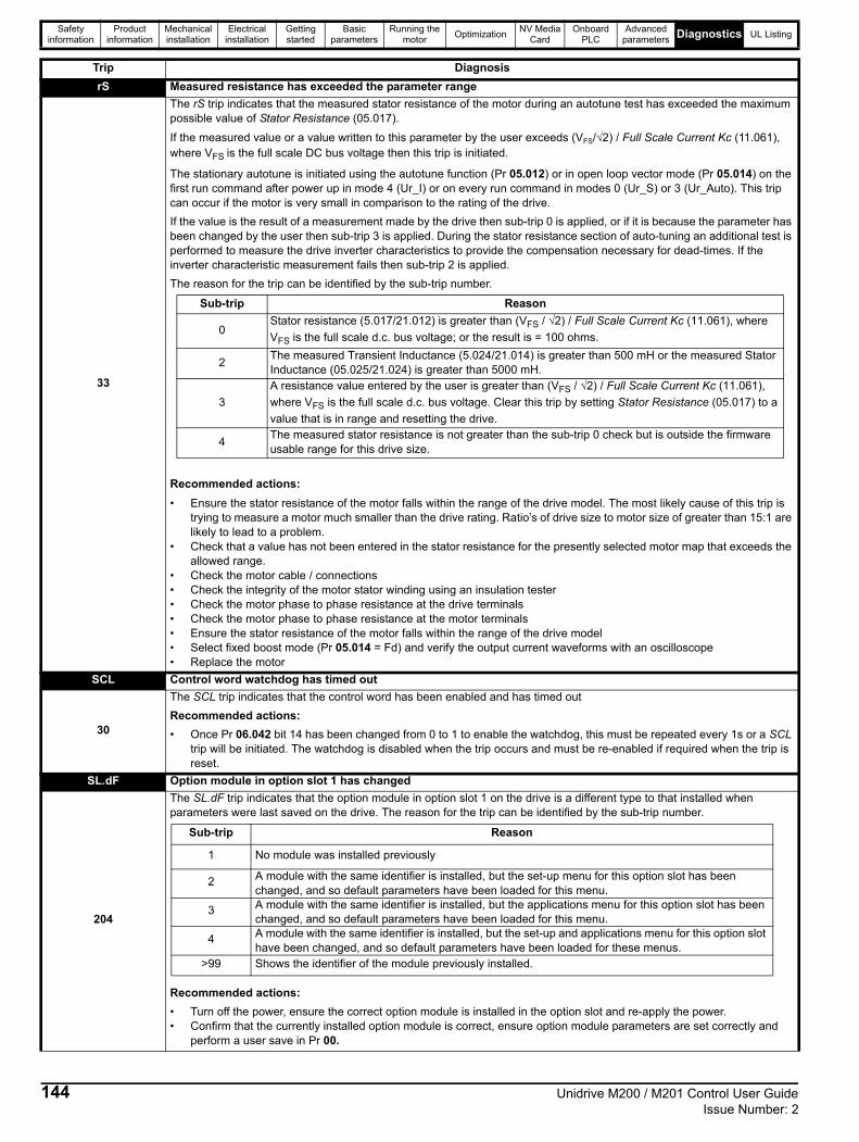
Safety information
Product information
Mechanical installation
Electrical installation
Getting started
Basic parameters
Running the motor
OptimizationNV Media
CardOnboard
PLCAdvanced
parameters Diagnostics UL Listing
rS Measured resistance has exceeded the parameter range
33
The rS trip indicates that the measured stator resistance of the motor during an autotune test has exceeded the maximum possible value of Stator Resistance (05.017).
If the measured value or a value written to this parameter by the user exceeds (VFS/√2) / Full Scale Current Kc (11.061), where VFS is the full scale DC bus voltage then this trip is initiated.
The stationary autotune is initiated using the autotune function (Pr 05.012) or in open loop vector mode (Pr 05.014) on the first run command after power up in mode 4 (Ur_I) or on every run command in modes 0 (Ur_S) or 3 (Ur_Auto). This trip can occur if the motor is very small in comparison to the rating of the drive.
If the value is the result of a measurement made by the drive then sub-trip 0 is applied, or if it is because the parameter has been changed by the user then sub-trip 3 is applied. During the stator resistance section of auto-tuning an additional test is performed to measure the drive inverter characteristics to provide the compensation necessary for dead-times. If the inverter characteristic measurement fails then sub-trip 2 is applied.
The reason for the trip can be identified by the sub-trip number.
Recommended actions:
• Ensure the stator resistance of the motor falls within the range of the drive model. The most likely cause of this trip is trying to measure a motor much smaller than the drive rating. Ratio’s of drive size to motor size of greater than 15:1 are likely to lead to a problem.
• Check that a value has not been entered in the stator resistance for the presently selected motor map that exceeds the allowed range.
• Check the motor cable / connections• Check the integrity of the motor stator winding using an insulation tester• Check the motor phase to phase resistance at the drive terminals• Check the motor phase to phase resistance at the motor terminals• Ensure the stator resistance of the motor falls within the range of the drive model• Select fixed boost mode (Pr 05.014 = Fd) and verify the output current waveforms with an oscilloscope• Replace the motor
SCL Control word watchdog has timed out
30
The SCL trip indicates that the control word has been enabled and has timed out
Recommended actions:
• Once Pr 06.042 bit 14 has been changed from 0 to 1 to enable the watchdog, this must be repeated every 1s or a SCL trip will be initiated. The watchdog is disabled when the trip occurs and must be re-enabled if required when the trip is reset.
SL.dF Option module in option slot 1 has changed
204
The SL.dF trip indicates that the option module in option slot 1 on the drive is a different type to that installed when parameters were last saved on the drive. The reason for the trip can be identified by the sub-trip number.
Recommended actions:
• Turn off the power, ensure the correct option module is installed in the option slot and re-apply the power.• Confirm that the currently installed option module is correct, ensure option module parameters are set correctly and
perform a user save in Pr 00.
Trip Diagnosis
Sub-trip Reason
0Stator resistance (5.017/21.012) is greater than (VFS / √2) / Full Scale Current Kc (11.061), where
VFS is the full scale d.c. bus voltage; or the result is = 100 ohms.
2The measured Transient Inductance (5.024/21.014) is greater than 500 mH or the measured Stator Inductance (05.025/21.024) is greater than 5000 mH.
3
A resistance value entered by the user is greater than (VFS / √2) / Full Scale Current Kc (11.061),
where VFS is the full scale d.c. bus voltage. Clear this trip by setting Stator Resistance (05.017) to a
value that is in range and resetting the drive.
4The measured stator resistance is not greater than the sub-trip 0 check but is outside the firmware usable range for this drive size.
Sub-trip Reason
1 No module was installed previously
2 A module with the same identifier is installed, but the set-up menu for this option slot has been changed, and so default parameters have been loaded for this menu.
3 A module with the same identifier is installed, but the applications menu for this option slot has been changed, and so default parameters have been loaded for this menu.
4 A module with the same identifier is installed, but the set-up and applications menu for this option slot have been changed, and so default parameters have been loaded for these menus.
>99 Shows the identifier of the module previously installed.
144 Unidrive M200 / M201 Control User Guide Issue Number: 2

Safety information
Product information
Mechanical installation
Electrical installation
Getting started
Basic parameters
Running the motor
OptimizationNV Media
CardOnboard
PLCAdvanced
parameters Diagnostics UL Listing
SL.Er Option module in option slot 1 has detected a fault
202
The SL.Er trip indicates that the option module in option slot 1 on the drive has detected an error. The reason for the error can be identified by the sub-trip number. As default, the sub-trip number is shown as a number on the display. However, it is possible for the option module to supply sub-trip number strings which will be displayed instead of the number if available.
Recommended actions:
• See relevant Option Module User Guide for details of the trip
SL.HF Option module 1 hardware fault
200
The SL.HF trip is generated by the drive. The possible causes of the trip can be identified by the sub-trip number.
Recommended actions:
• Ensure the option module is installed correctly • Replace the option module • Replace the drive
SL.nF Option module in option slot 1 has been removed
203
The SL.nF trip indicates that the option module in option slot 1 on the drive has been removed since the last power up.
The sub-trip number gives the ID code of the option module that has been removed.
Recommended actions:
• Ensure the option module is installed correctly. • Re-install the option module. • To confirm that the removed option module is no longer required perform a save function in Pr 00.
SL.tO Option module watchdog function service error
201
The SL.tO trip indicates that the option module installed in Slot 1 has started the option watchdog function and then failed to service the watchdog correctly.
Recommended actions:
• Replace the option module
So.St Soft start relay failed to close, soft start monitor failed
226
The So.St trip indicates that the soft start relay in the drive failed to close or the soft start monitoring circuit has failed.The cause of the trip can be identified by the sub-trip number.
Recommended actions:
• Hardware fault – Contact the supplier of the drive
St.HF Hardware trip has occurred during last power down
221
The St.HF trip indicates that a hardware trip (HF01 –HF18) has occurred and the drive has been power cycled. The sub-trip number identifies the HF trip.
Recommended actions:
• Enter 1299 in Pr 00 and press reset to clear the trip
Trip Diagnosis
Sub-trip Reason
1 The module category cannot be identified
2 All the required customized menu table information has not been supplied or the tables supplied are corrupt
3 There is insufficient memory available to allocate the comms buffers for this module
4 The module has not indicated that it is running correctly during drive power-up
5 Module has been removed after power-up or it has stopped working
6 The module has not indicated that it has stopped accessing drive parameters during a drive mode change
7 The module has failed to acknowledge that a request has been made to reset the drive processor
8 The drive failed to read correctly the menu table from the module during drive power-up.
9 The drive failed to upload menu tables from the module and timed-out (5s).
10 Menu table CRC invalid.
Sub-trip Reason
1 Soft-start failure
2 DC bus capacitor failure on 110 V drive (size 2 only)
Unidrive M200 / M201 Control User Guide 145Issue Number: 2

Safety information
Product information
Mechanical installation
Electrical installation
Getting started
Basic parameters
Running the motor
OptimizationNV Media
CardOnboard
PLCAdvanced
parameters Diagnostics UL Listing
Sto No Safe Torque Off board fitted
234
Internal STO board not fitted correctly
Recommended actions:
Hardware fault – Contact the supplier of the drive
th Motor thermistor over-temperature
24
The th trip indicates that the motor thermistor connected to terminal 14 (digital input 5) on the control connections has indicated a motor over temperature. If Digital Input 5 Mode (08.035) is 2 then a th trip is initiated if the feedback value is higher than Thermistor Trip Threshold (07.048).
Recommended actions:
• Check threshold level (Pr 07.048)• Check motor temperature• Check thermistor continuity
th.br Brake resistor over temperature
10
The th.br trip is initiated if the hardware based braking resistor thermal monitoring is connected and the resistor overheats. If the braking resistor is not used, then this trip must be disabled with bit 3 of Action On Trip Detection (10.037) to prevent this trip.
Recommended actions:
• Check brake resistor wiring• Check braking resistor value is greater than or equal to the minimum resistance value• Check braking resistor insulation
tH.Fb Internal thermistor has failed
218
The tH.Fb trip indicates that an internal thermistor has failed in the drive (i.e. open circuit or short circuit). The thermistor location can be identified by the sub-trip number.
Recommended actions:
• Hardware fault – Contact the supplier of the drive
thS Motor thermistor short circuit
25
The thS trip indicates that the motor thermistor connected to terminal 14 (digital input 5) on the control connections, is short circuit or low impedance (<50 ).
Recommended actions:
• Check thermistor continuity• Replace motor / motor thermistor
tun.S Autotune test stopped before completion
18
The drive was prevented from completing an autotune test, because either the drive enable or the drive run were removed.
Recommended actions:
• Check the drive enable signal (Terminal 11) was active during the autotune• Check the run command was active in digital input 3 or 4 state (Pr 08.003 or Pr 08.004) during the autotune.
tun.1 Required speed could not be reached
11
The drive has tripped during an autotune. The cause of the trip can be identified from the sub-trip number.
Recommended actions:
• Ensure the motor is free to turn i.e. mechanical brake is released• Ensure Mechanical Load Test Level (05.021) is set correctly
tun.3 Measured inertia has exceeded the parameter range (RFC-A mode only)
13
The drive has tripped during a rotating autotune or mechanical load measurement test. The cause of the trip can be identified from the associated sub-trip number.
Recommended actions:
• Check motor cable wiring is correct
Trip Diagnosis
Source xx y zz
Power system 01 0 Thermistor location defined by zz
Power system 01 1 Thermistor location defined by zz in the rectifier
Sub-trip Reason
2 The motor did not reach the required speed during rotating autotune or mechanical load measurement
Sub-trip Reason
1 Measured inertia has exceeded the parameter range during a mechanical load measurement
3 The mechanical load test has been unable to identify the motor inertia
146 Unidrive M200 / M201 Control User Guide Issue Number: 2

Safety information
Product information
Mechanical installation
Electrical installation
Getting started
Basic parameters
Running the motor
OptimizationNV Media
CardOnboard
PLCAdvanced
parameters Diagnostics UL Listing
U.OI User OI ac
8 The U.OI trip is initiated if the output current of the drive exceeds the trip level set by User Over Current Trip Level (04.041).
U.S User Save error / not completed
36
The U.S trip indicates that an error has been detected in the user save parameters saved in non-volatile memory. For example, following a user save command, If the power to the drive was removed when the user parameters were being saved.
Recommended actions:
• Perform a user save in Pr 00 to ensure that the trip doesn’t occur the next time the drive is powered up.• Ensure that the drive has enough time to complete the save before removing the power to the drive.
UP.uS Trip generated by an onboard user program
96
This trip can be initiated from within an onboard user program using a function call which defines the sub-trip number.
Recommended actions:
• Check the user program
Trip Diagnosis
Unidrive M200 / M201 Control User Guide 147Issue Number: 2

Safety information
Product information
Mechanical installation
Electrical installation
Getting started
Basic parameters
Running the motor
OptimizationNV Media
CardOnboard
PLCAdvanced
parameters Diagnostics UL Listing
UPrG Onboard user program error
249
Trip Diagnosis
An error has been detected in the onboard user program image. The sub-trip indicated the reason for the trip.
The following table shows the differences when compared to the derivative product image.
Sub-trip
Reason Comments
1 Divide by zero.
2 Undefined trip.
3 Attempted fast parameter access set-up with non-existent parameter.
4 Attempted access to non-existent parameter.
5 Attempted write to read-only parameter.
6 Attempted an over-range write.
7 Attempted read from write-only parameter.
30The image has failed because either its CRC is incorrect, or there are less than 6 bytes in the image or the image header version is less than 5.
Occurs when the drive powers-up or the image is programmed. The image tasks will not run.
31 The image requires more RAM for heap and stack than can be provided by the drive. As 30.
32 The image requires an OS function call that is higher than the maximum allowed. As 30.
33 The ID code within the image is not valid. As 30.
34 The user program image has been changed for an image with a different user program number. As 30.
40 The timed task has not completed in time and has been suspended.Onboard User Program: Enable (11.047) is reset to zero when the trip is initiated.
41 Undefined function called, i.e. a function in the host system vector table that has not been assigned. As 40.
52 Customizable menu table CRC check failed. As 30.
53 Customizable menu table changed.
Occurs when the drive powers-up or the image is programmed and the table has changed. Defaults are loaded for the user program menu and the trip will keep occurring until drive parameters are saved.
80 *Image is not compatible with the control board Initiated from within the image code.
81 *Image is not compatible with the control board serial number
100 Image has detected and prevented attempted pointer access outside of the IEC task's heap area.
101 Image has detected and prevented misaligned pointer usage.
102 Image has detected an array bounds violation and prevented its access.
103Image has attempted to convert a data type to or from an unknown data type, has failed and has shut itself down.
104 Image has attempted to use an unknown user service function.
200User program has invoked a "divide" service with a denominator of zero. (Note that this is raised by the downloaded image and has therefore been given a distinct error code despite being the same fundamental problem as sub-trip 1.)
201 Parameter access is not supported. An attempt to read database other than the host drive.
202 Parameter does not exist. Database was host drive but the specified parameter does not exist.
203 Parameter is read-only.
204 Parameter is write-only.
205 Unknown parameter error.
206 Invalid bit present in parameter. The parameter does not contain the specified bit.
207 Parameter format lookup failed. Failed to get parameter information data.
208 An over-range write has been attempted.
Sub-trip Difference
40,41 Onboard User Program: Enable (11.047) is reset to zero when the trip is initiated.
51 Not applicable as core menu Customization not allowed.
6x Not applicable as option module restrictions not allowed.
7x Not applicable as option module restrictions not allowed.
100 Image has detected and prevented attempted pointer access outside of the IEC task's heap area.
101 Image has detected and prevented misaligned pointer usage.
102 Image has detected an array bounds violation and prevented its access.
103 Image has attempted to convert a data type to or from an unknown data type, has failed and has shut itself down.
104 Image has attempted to use an unknown user service function.
200User program has invoked a "divide" service with a denominator of zero. (Note that this is raised by the downloaded image and has therefore been given a distinct error code despite being the same fundamental problem as sub-trip 1)
148 Unidrive M200 / M201 Control User Guide Issue Number: 2

Safety information
Product information
Mechanical installation
Electrical installation
Getting started
Basic parameters
Running the motor
OptimizationNV Media
CardOnboard
PLCAdvanced
parameters Diagnostics UL Listing
Table 12-3 Serial communications look up table
The trips can be grouped into the following categories. It should be noted that a trip can only occur when the drive is not tripped or is already tripped but with a trip with a lower priority number.
No Trip No Trip No Trip
1 rES 90 LF.Er 199 dESt
2 OV 91 rES 200 SL.HF
3 OI.AC 92 OI.Sn 201 SL.tO
4 OI.br 93 Pb.Er 202 SL.Er
5 PSU 94 - 95 rES 203 SL.nF
6 Et 96 UP.uS 204 SL.dF
7 O.SPd 97 d.Ch 205 - 214 rES
8 U.OI 98 Out.P 215 rES
9 rES 99 rES 216 - 217 rES
10 th.br 100 rESEt 218 tH.Fb
11 tun.1 101 rES 219 Oht.C
12 rES 102 rES 220 P.dAt
13 tun.3 103 - 108 rES 221 St.HF
14 - 17 rES 109 rES 222 rES
18 tun.S 110 dcct 223 - 224 rES
19 It.br 111 rES 225 Cur.O
20 It.Ac 112 - 167 t112 - t167 226 So.St
21 Oht.I 168 - 172 rES 227 r.All
22 Oht.P 173 FAn.F 228 OI.SC
23 rES 174 C.SL 229 rES
24 th 175 C.Pr 230 rES
25 thS 176 rES 231 Cur.c
26 O.Ld1 177 rES 232 dr.CF
27 Oh.dc 178 C.by 233 rES
28 cL.A1 179 C.d.E 234 Sto
29 rES 180 C.OPt 235 Pb.HF
30 SCL 181 C.rdo 236 no.PS
31 EEF 182 C.Err 237 FI.In
32 PH.Lo 183 C.dAt 238 - 244 rES
33 rS 184 C.FuL 245 Pb.bt
34 PAd 185 C.Acc 246 dEr.E
35 CL.bt 186 C.rtg 247 Fi.Ch
36 U.S 187 C.tyP 248 dEr.I
37 Pd.S 188 C.cPr 249 UPrG
38 rES 189 OI.A1 250 r.b.ht
39 rES 190 rES 251 - 254 rES
40 - 89 t040 - t089 191 - 198 rES 255 rSt.L
Unidrive M200 / M201 Control User Guide 149Issue Number: 2

Safety information
Product information
Mechanical installation
Electrical installation
Getting started
Basic parameters
Running the motor
OptimizationNV Media
CardOnboard
PLCAdvanced
parameters Diagnostics UL Listing
Table 12-4 Trip categories
12.5 Internal / Hardware tripsTrips HF01 to HF23 are internal faults that do not have trip numbers except HF08, HF11, HF12 and HF18. If one of these trips occurs, the main drive processor has detected an irrecoverable error. All drive functions are stopped and the trip message will be displayed on the drive keypad. If a non permanent trip occurs this may be reset by power cycling the drive. On power up after it has been power cycled the drive will trip on St.HF (the sub-trip number indicates the HF fault code). Enter 1299 in Pr 00 to clear the Stored HF trip.
12.6 Alarm indicationsIn any mode, an alarm is an indication given on the display by alternating the alarm string with the drive status string display. If an action is not taken to eliminate any alarm except "tuning”, “LS" or “24.LoSt” the drive may eventually trip. Alarms are not displayed when a parameter is being edited.
Table 12-5 Alarm indications
Priority Category Trips Comments
1 Internal faults HFxxThese indicate internal problems and cannot be reset. All drive features are inactive after any of these trips occur.
1 Stored HF trip St.HFThis trip cannot be cleared unless 1299 is entered into Parameter (00) and a reset is initiated.
2 Non-resettable tripsTrip numbers 218 to 247, SL.HF
These trips cannot be reset.
3 Volatile memory failure EEFThis can only be reset if Parameter 00 is set to 1233 or 1244, or if Load Defaults (11.043) is set to a non-zero value.
4 NV Media Card tripsTrip numbers 174, 175 and 177 to 188
These trips are priority 5 during power-up.
4 Internal 24V PSU Rectifier 24 V
5Trips with extended reset times
OI.AC, OI.br, and FAn.F
These trips cannot be reset until 10 s after the trip was initiated.
5Phase loss and d.c. link power circuit protection
PH.Lo and Oh.dc
The drive will attempt to stop the motor before tripping if a PH.Lo trip occurs unless this feature has been disabled (see Action On Trip Detection (10.037). The drive will always attempt to stop the motor before tripping if an Oh.dc occurs.
5 Standard trips All other trips
Alarm string Description
br.resBrake resistor overload. Braking Resistor Thermal Accumulator (10.039) in the drive has reached 75.0 % of the value at which the drive will trip.
OV.LdMotor Protection Accumulator (04.019) in the drive has reached 75.0 % of the value at which the drive will trip and the load on the drive is >100 %.
d.OV.Ld Drive over temperature. Percentage Of Drive Thermal Trip Level (07.036) in the drive is greater than 90 %.
tuning The autotune procedure has been initialized and an autotune in progress.
LS Limit switch active. Indicates that a limit switch is active and that is causing the motor to be stopped.
Opt.AI Option slot alarm.
Lo.AC Low voltage mode. See Low AC Alarm (10.107).
I.AC.Lt Current limit active. See Current Limit Active (10.009).
24.LoSt 24V backup not present. See 24V Alarm Loss Enable (11.098)
150 Unidrive M200 / M201 Control User Guide Issue Number: 2

Safety information
Product information
Mechanical installation
Electrical installation
Getting started
Basic parameters
Running the motor
OptimizationNV Media
CardOnboard
PLCAdvanced
parameters Diagnostics UL Listing
12.7 Status indications
Table 12-6 Status indications
Table 12-7 Option module and NV Media Card and other status indications at power-up
12.8 Displaying the trip historyThe drive retains a log of the last ten trips that have occurred. Trip 0 (10.020) to Trip 9 (10.029) store the most recent 10 trips that have occurred where Trip 0 (10.020) is the most recent and Trip 9 (10.029) is the oldest. When a new trip occurs it is written to Trip 0 (10.020) and all the other trips move down the log, with oldest being lost. The date and time when each trip occurs are also stored in the date and time log, i.e. Trip 0 Date (10.041) to Trip 9 Time (10.060). The date and time are taken from Date (06.016) and Time (06.017). Some trips have sub-trip numbers which give more detail about the reason for the trip. If a trip has a sub-trip number its value is stored in the sub-trip log, i.e. Trip 0 Sub-trip Number (10.070) to Trip 9 Sub-trip Number (10.079). If the trip does not have a sub-trip number then zero is stored in the sub-trip log.
If any parameter between Pr 10.020 and Pr 10.029 inclusive is read by serial communication, then the trip number in Table 12-2 is the value transmitted.
The trip logs can be reset by writing a value of 255 in Pr 10.038 (via serial communications only).
String Description Drive output stage
inhThe drive is inhibited and cannot be run. Either the drive enable signal is not applied to the drive enable terminals or Pr 06.015 is set to 0.
Disabled
rdyThe drive is ready to run. The drive enable is active, but the drive inverter is not active because the final drive run is not active.
Disabled
StoP The drive is stopped / holding zero speed. Enabled
S.Loss Supply loss condition has been detected. Enabled
dc.inJ The drive is applying dc injection braking. Enabled
Er The drive has tripped and no longer controlling the motor. The trip code appears in the display. Disabled
UV The drive is in the under voltage state either in low voltage or high voltage mode. Disabled
HEAt The motor pre-heat function is active Enabled
String Status
PS.LOAD Waiting for power stageThe drive is waiting for the processor in the power stage to respond after power-up.
LOAD OPtion Waiting for an option moduleThe drive is waiting for the Option Module to respond after power-up.
UPLOAD Loading parameter databaseAt power-up it may be necessary to update the parameter database held in the drive because an option module has changed. This may involve data transfer between the drive and option module. During this period 'UPLOAD' is displayed.
LOAD.I Bootloading drive firmwareThe drive is waiting for the bootloader file to be transferred to the processor.
NOTE
Unidrive M200 / M201 Control User Guide 151Issue Number: 2

Safety information
Product information
Mechanical installation
Electrical installation
Getting started
Basic parameters
Running the motor
OptimizationNV Media
CardOnboard
PLCAdvanced
parameters Diagnostics UL Listing
12.9 Behaviour of the drive when trippedIf the drive trips, the output of the drive is disabled so the load coasts to a stop. If any trip occurs, the following read only parameters are frozen until the trip is cleared. This is to help diagnose the cause of the trip.
If the parameters are not required to be frozen then this can be disabled by setting bit 4 of Pr 10.037.
Parameter Description
01.001 Frequency reference
01.002 Pre-skip filter reference
01.003 Pre-ramp reference
01.069 Reference in rpm
01.070 Clamped reference
02.001 Post-ramp reference
03.001 Final demand ref
03.002 Estimated frequency
03.003 Frequency error
03.004 Frequency controller output
03.045 Frequency reference
04.001 Current magnitude
04.002 Active current
04.017 Reactive current
05.001 Output frequency
05.002 Output voltage
05.003 Power
05.005 DC bus voltage
07.001 Analog input 1
07.002 Analog input 2
152 Unidrive M200 / M201 Control User Guide Issue Number: 2

Safety information
Product information
Mechanical installation
Electrical installation
Getting started
Basic parameters
Running the motor
OptimizationNV Media
CardOnboard
PLCAdvanced
parametersDiagnostics UL Listing
13 UL Listing
13.1 UL file referenceAll models are UL Listed to both Canadian and US requirements. The UL file reference is: NMMS/7.E171230.
13.2 Option modules, kits and accessoriesOption Modules, Control Pods, Installation Kits and other accessories for use with these drives are UL Listed.
13.3 Enclosure ratingsAll models are Open Type as supplied.
The drive enclosure is not classified as a fire enclosure. A separate fire enclosure must be provided. A UL/ NEMA Type 12 enclosure is suitable.
When fitted with a conduit box the drives meet the requirements for UL Type 1. Type 1 enclosures are intended for indoor use, primarily to provide a degree of protection against limited amounts of falling dirt.
The drives meet the requirements for UL Type 12 when installed inside a Type 12 enclosure and through-hole mounted using the sealing kit and the high-IP insert (where provided).
When through-hole mounted, the drives have been evaluated as
suitable for use in surrounding air temperatures up to 40 oC.
Remote Keypads are UL Type 12 when installed with the sealing washer and fixing kit provided.
When installed in a Type 1 or Type 12 enclosure, the drives may be operated in a compartment handling conditioned air.
13.4 MountingDrives may be surface, through-panel or tile mounted using the appropriate brackets. Drives may be mounted singly or side by side with suitable space between them (bookcase mounting).
13.5 EnvironmentDrives must be installed in a Pollution Degree 2 environment or better (dry, non-conductive pollution only).
The drives have been evaluated for use at ambient temperatures up to
40 °C. The drives have additionally been evaluated for 50 oC and 55 oC ambient air temperatures with a derated output.
13.6 Electrical InstallationOVERVOLTAGE CATEGORY
OVC III
SUPPLY
The drives are suitable for use on a circuit capable of delivering not more than 100,000 RMS symmetrical amperes, 600 Volts AC Maximum.
TERMINAL TORQUE
Terminals must be tightened to the rated torque as specified in the Installation Instructions.
WIRING TERMINALS
Drives must be installed using cables rated for 75 °C operation, copper wire only.
Where possible, UL Listed closed-loop connectors sized according to the field wiring shall be used for all field power wiring connections.
GROUND CONNECTION INSTRUCTIONS
UL Listed closed-loop connectors sized according to the field wiring shall be used for grounding connections.
BRANCH CIRCUIT PROTECTION
The fuses and circuit breakers required for branch circuit protection are specified in the Installation Instructions.
OPENING OF BRANCH CIRCUIT
Opening of the branch-circuit protective device may be an indication that a fault has been interrupted. To reduce the risk of fire or electric shock, the equipment should be examined and replaced if damaged. If burnout of the current element of an overload relay occurs, the complete overload relay must be replaced.
Integral solid state short circuit protection does not provide branch circuit protection. Branch circuit protection must be provided in accordance with the National Electrical Code (NEC), The Canadian Electrical Code, and any additional local codes.
DYNAMIC BRAKING
M100, M101, M200, M201, M300 or M400, frame sizes 1 to 4 have been evaluated for dynamic braking applications. Other drive models have not been evaluated for dynamic braking.
13.7 Motor overload protection and thermal memory retention
All drives incorporate internal overload protection for the motor load that does not require the use of an external or remote overload protection device.
The protection level is adjustable and the method of adjustment is provided in section 8.4 Motor thermal protection on page 54. Maximum current overload is dependent on the values entered into the current limit parameters (motoring current limit, regenerative current limit and symmetrical current limit entered as percentage) and the motor rated current parameter (entered in amperes).
The duration of the overload is dependent on motor thermal time constant. The maximum programmable time constant depends on the drive model. The method of adjustment of the overload protection is provided.
The drives are provided with user terminals that can be connected to a motor thermistor to protect the motor from high temperature, in the event of a motor cooling fan failure.
13.8 External Class 2 supplyThe external power supply used to power the 24 V control circuit shall be marked: "UL Class 2". The power supply voltage shall not exceed 24 Vdc.
13.9 Modular Drive SystemsDrives with DC+ and DC- supply connections, rated 230 V or 480 V have been investigated for use in Modular Drive Systems as inverters when supplied by the converter sections from the Unidrive-M range. In these applications the inverters are required to be additionally protected by supplemental fuses.
Alternatively, the inverters may be supplied by converter models: Mentor MP25A, 45A, 75A, 105A, 155A or 210A.
Contact the supplier of the drive for more information.
Unidrive M200 / M201 Control User Guide 153Issue Number: 2

Safety information
Product information
Mechanical installation
Electrical installation
Getting started
Basic parameters
Running the motor
OptimizationNV Media
CardOnboard
PLCAdvanced
parametersDiagnostics UL Listing
13.10 Requirement for Transient Surge Suppression
This requirement only applies to Frame Size 7 drives with rated input voltage = 575 V.
TRANSIENT SURGE SUPPRESSION SHALL BE INSTALLED ON THE LINE SIDE OF THIS EQUIPMENT AND SHALL BE RATED 575 Vac (PHASE TO GROUND), 575 Vac (PHASE TO PHASE), SUITABLE FOR OVERVOLTAGE CATEGORY III, AND SHALL PROVIDE PROTECTION FOR A RATED IMPULSE VOLTAGE TO WITHSTAND VOLTAGE PEAK OF 6 kV AND A CLAMPING VOLTAGE OF MAXIMUM 2400 V.
154 Unidrive M200 / M201 Control User Guide Issue Number: 2

Index
AAcceleration ..................................................................... 46, 47Advanced menus ....................................................................26Advanced parameters .............................................................67Alarm .....................................................................................150Alarm Indications ...................................................................150Autotune ..................................................................................49
BBasic requirements .................................................................41
CCautions ....................................................................................7Control connections ................................................................20Control terminal specification ..................................................21Current limits ...........................................................................54
DDeceleration ..................................................................... 46, 47Defaults (restoring parameter) ................................................27Destination parameter .............................................................20Diagnostics ............................................................................129Display ....................................................................................23Display messages ...................................................................26
FField weakening (constant power) operation ...........................55Fixed V/F mode .......................................................................11
GGetting Started ........................................................................23
KKeypad ....................................................................................23
MMagnetising current ................................................................ 73Maximum frequency ............................................................... 55Mechanical Installation ........................................................... 15Menu 0 .................................................................................... 25Menu 01 - Frequency / speed reference ................................ 78Menu 02 - Ramps ................................................................... 82Menu 03 - Slave frequency, speed feedback and speed control ..................................................................................... 85Menu 04 - Torque and current control .................................... 90Menu 05 - Motor control ......................................................... 93Menu 06 - Sequencer and clock ............................................. 98Menu 07 - Analog I/O ........................................................... 101Menu 08 - Digital I/O ............................................................. 104Menu 09 - Programmable logic, motorized pot and binarysum ....................................................................................... 108Menu 10 - Status and trips ................................................... 112Menu 11 - General drive set-up ............................................ 114Menu 12 - Threshold detectors and variable selectors ......... 115Menu 14 - User PID controller .............................................. 120Menu 18 - Application menu 1 .............................................. 124Menu 19 - Application menu 2 .............................................. 125Menu 20 - Application menu 3 .............................................. 125Menu 21 - Second motor parameters ................................... 126Menu 22 - Additional Menu 0 set-up ..................................... 127Menu structure ........................................................................ 25Minimum connections to get the motor running in anyoperating mode ....................................................................... 42Mode parameter ..................................................................... 20Motor (running the motor) ....................................................... 41Motor number of poles ............................................................ 48Motor rated current ................................................................. 48Motor rated current (maximum) .............................................. 54Motor rated frequency ............................................................ 48Motor rated power factor ..................................................48, 73Motor rated speed .................................................................. 48Motor rated voltage ................................................................. 48Motor thermal protection ......................................................... 54
NNotes ........................................................................................ 7
OOpen loop mode ..................................................................... 11Open loop vector mode .......................................................... 11Operating mode (changing) ..............................................26, 41Operating modes .................................................................... 11Optimization ............................................................................ 48Options ................................................................................... 13
PParameter access level .......................................................... 27Parameter ranges ................................................................... 70Parameter security ................................................................. 27Product information .................................................................. 9
QQuick start commissioning ...................................................... 47Quick start commissioning / Start-up ...................................... 46Quick start connections .......................................................... 41
Unidrive M200 / M201 Control User Guide 155Issue Number: 2

RRelay contacts ........................................................................22RFC-A mode ...........................................................................11
SSafety Information .............................................................. 7, 65Saving parameters ..................................................................26Serial comms lead ..................................................................20Serial communications connections ........................................19Serial communications look-up table ....................................130Single line descriptions ...........................................................29Status ....................................................................................151Status Indications ..................................................................151Switching frequency ................................................................55
TTrip ........................................................................................129Trip History ............................................................................151Trip Indications ......................................................................129
UUser Security ..........................................................................27
VVoltage mode ................................................................... 49, 50
WWarnings ...................................................................................7
156 Unidrive M200 / M201 Control User Guide Issue Number: 2


0478-0351-02


