Control Switches - Digi-Key Sheets/Airpax PDFs/22.5mm Metal... · 293 Control Switches and...
8
Airpax Corporation 807 Woods Road Cambridge, Maryland 21613 USA Tel: 410-228-1500 Fax: 410-228-3456 [email protected] Control Switches and Signaling Devices 22.5 mm Metal Series Control Switches and Signaling Devices, 22.5mm Metal Series 292 Non-Illuminated Operators, 22.5mm Metal Series 294 Illuminated Operators, 22.5mm Metal Series 296 Pilot Lights and Lens Assemblies, 22.5mm Metal Series 297 Control Switches and Signaling Devices, 22.5mm Metal Series 298
Transcript of Control Switches - Digi-Key Sheets/Airpax PDFs/22.5mm Metal... · 293 Control Switches and...

Airpax Corporation807 Woods RoadCambridge, Maryland21613 USATel: 410-228-1500Fax: [email protected]
Control Switchesand Signaling Devices 22.5 mm Metal Series
Control Switches and Signaling Devices, 22.5mm Metal Series 292
Non-Illuminated Operators, 22.5mm Metal Series 294
Illuminated Operators, 22.5mm Metal Series 296
Pilot Lights and Lens Assemblies, 22.5mm Metal Series 297
Control Switches and Signaling Devices, 22.5mm Metal Series 298

292
Con
trol S
witc
hes
and
Sign
alin
g D
evice
s
Control Switches and Signaling Devices, 22.5mm Metal SeriesThis range of 22.5mm metal series pushbuttons, selector switches, illuminated switches and pilot lights have been designed to provide the following features:
• Economy of space • Aesthetically pleasing • Self wiping contacts • Heavy-duty construction • RoHS compliant • Shrouded terminals •Simpletomount(onlyneedascrewdriver) •Verygoodflameresistance • Mounting method is unaffected • Use of LEDs for long life by excessive vibration • Electric shock protection (grounded unit)
ActuatorsThe circular actuators have chrome plated metal bezels and are functionally interchangeable on the different contact elements.
Contact elementsThe contact elements are double break and have self-wiping contacts. The elements are interchangeable and can be stacked without additional hardware. 1 to 6 elements (NO or NC) can be used for non-illuminated actuators, whereas, 1 to 4 elements (NO or NC) can be used for illuminated actuators. Gold NO or NC contact elements for low voltage, low current, < 25mA, switching applications are available.
Illuminated pushbuttons and pilot lightsPilotlightsandpushbuttonswitchesaresuitablefordirectconnectionthroughaseriesresistor,seriesresistoranddiode,usingbayonetcapfilamentbulb type BA9s as follows: Supply voltage for direct connection without series resistor . . . . 6V - 130V Supply voltage through series resistor . . . . . . . . . . . . . . . . . . . . 12V - 415V Supply voltage through resistor and diode . . . . . . . . . . . . . . . . . 230 VAC Bulb . . . . . . . . . . . . . . . . . . . . . . . . . . . . . . . . . . . . . . . . . . . . . . . Filament, type BA9S with OAL max. 28mm
Pilot lights and illuminated actuators are available with integral LEDs, suitable for operating at various voltages; 6V, 12V, 24V, 30V, 48V, 63.3V, 110V, 125V, 230VAC or DC and 415VAC. Pilot lights and illuminated actuators are available with LED bulbs (bayonet cap, BA9s design with OAL max. 28mm) suitable for operating at various voltages; 24V, 48V, 110V and 230V. On request an extra short circuit protection consisting of built-in fuse in the LED modules can be provided. Pilot lights are available with built -in transformers suitable for operating at 110VAC, 230VAC input and 6V, 12V and 24V output.
TerminalsContact elements and pilot lights are designed to have shrouded terminals with combination screws.
MountingThe metal series control devices 22.5mm can be mounted in any position on panels of 1 to 6 mm thickness. We recommend minmum mounting centers of30mmx40mm.However,thedimensionsandconfigurationshouldbedecided on the basis of the application. The actuators and the lens assemblies lock on the holding bracket. See assembly details.
Electrical and mechanical characteristicsEnvironmentStandards conformity: CSA - C22.2 No. 14-95, UL508, EN60947-5-1 2000Approvals: CSA - C22.2 No. 14-95, UL508, VDE0660Degree of protection: IP 65 as per IEC529, NEMA 4X, 12 as per UL50Ambient temperature: -25°C to +70°COperating position: All positions
Contact element blockElement screw torque: 3 - 4 in/lbsConnection screw torque: 5 - 7 in/lbsRated insulationvoltage: 500VRated thermal current: 10AContact operation: Self wiping, slow break NO or NCMake and break capacity as per IEC 947-5-(1) 1990: AC 15 - 4A, 415VAC DC 13 - 0.5A, 110VDC as per CSA - C22.2 No. 14-95, UL508 A 600 Q 600
Terminal capacity: Minimum 1 X 0.5mm2 (20AWG), maximum 2 x 15mm2 (2x16AWG), or 1 x 2.5mm2 (1x14AWG)
Terminals marking: 1-2 for NC, 3-4 for NOShort circuit protection: 10A cartridge fuse, HRC type, rated for resistive loadingMechanical life: Over one million operationsElectrical rating: (one million operating cycles at 3600 cycles per hour, load factor 0.5) V 24 120 230 V 24 110 AC15 DC13 A 4 3 2 A 0.5 0.2
Modules for pilot lights and illuminated switches with integral LED / LED bulb (BA9S cap)Current consumption (applicatable to all colors)
24VAC/DC, 110VAC and 240VAC: max. 20mA110VDC: max. 15mA220VDC: max. 10mAService life(at nominial voltage and at ambient temperature): 100,000 hoursVoltage limits (nominal voltage): ±20% of rated voltageShortcircuitprotection: onspecificrequestTerminal capacity: min. 1 X 0.5mm2 (20AWG) max. 2 x 1.5mm2 (2x16AWG) or 1 x 2.5mm2 (1x14AWG)
40X
30
43 24 24
Ø 22.5 DIN
30
40
Mounting details
Mounting bracket screws torque 8 - 10 in/lbs
293
Con
trol S
witc
hes
and
Sign
alin
g D
evice
s
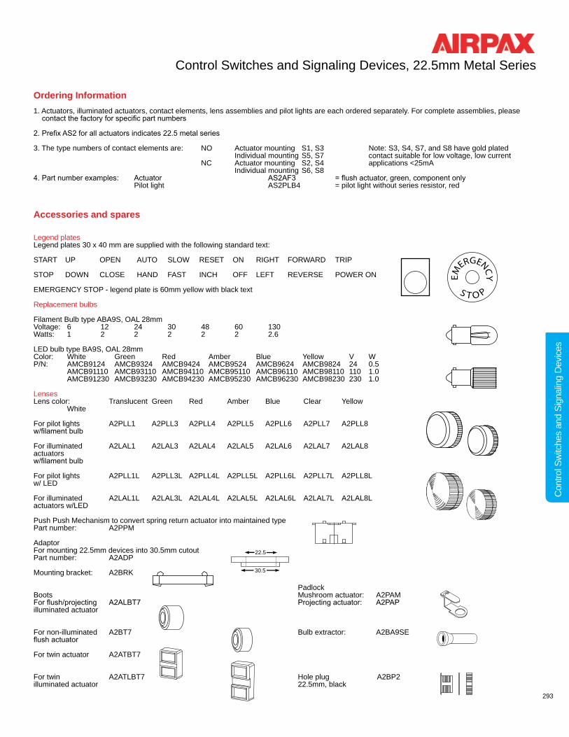
Ordering Information1. Actuators, illuminated actuators, contact elements, lens assemblies and pilot lights are each ordered separately. For complete assemblies, please contactthefactoryforspecificpartnumbers
2.PrefixAS2forallactuatorsindicates22.5metalseries
3. The type numbers of contact elements are: NO Actuator mounting S1, S3 Note: S3, S4, S7, and S8 have gold plated Individual mounting S5, S7 contact suitable for low voltage, low current NC Actuator mounting S2, S4 applications <25mA Individual mounting S6, S8 4.Partnumberexamples: Actuator AS2AF3 =flushactuator,green,componentonly Pilot light AS2PLB4 = pilot light without series resistor, red
Accessories and spares
Legend platesLegend plates 30 x 40 mm are supplied with the following standard text:
START UP OPEN AUTO SLOW RESET ON RIGHT FORWARD TRIP
STOP DOWN CLOSE HAND FAST INCH OFF LEFT REVERSE POWER ON
EMERGENCY STOP - legend plate is 60mm yellow with black text
Replacement bulbs
Filament Bulb type ABA9S, OAL 28mmVoltage: 6 12 24 30 48 60 130Watts: 1 2 2 2 2 2 2.6
LED bulb type BA9S, OAL 28mmColor: White Green Red Amber Blue Yellow V WP/N: AMCB9124 AMCB9324 AMCB9424 AMCB9524 AMCB9624 AMCB9824 24 0.5 AMCB91110 AMCB93110 AMCB94110 AMCB95110 AMCB96110 AMCB98110 110 1.0 AMCB91230 AMCB93230 AMCB94230 AMCB95230 AMCB96230 AMCB98230 230 1.0
LensesLens color: Translucent Green Red Amber Blue Clear Yellow White
For pilot lights A2PLL1 A2PLL3 A2PLL4 A2PLL5 A2PLL6 A2PLL7 A2PLL8w/filamentbulb
For illuminated A2LAL1 A2LAL3 A2LAL4 A2LAL5 A2LAL6 A2LAL7 A2LAL8actuators w/filamentbulb
For pilot lights A2PLL1L A2PLL3L A2PLL4L A2PLL5L A2PLL6L A2PLL7L A2PLL8Lw/ LED
For illuminated A2LAL1L A2LAL3L A2LAL4L A2LAL5L A2LAL6L A2LAL7L A2LAL8Lactuators w/LED
Push Push Mechanism to convert spring return actuator into maintained typePart number: A2PPM
Adaptor For mounting 22.5mm devices into 30.5mm cutoutPart number: A2ADP
Mounting bracket: A2BRK
PadlockBoots Mushroom actuator: A2PAM Forflush/projecting A2ALBT7 Projectingactuator: A2PAPilluminated actuator
For non-illuminated A2BT7 Bulb extractor: A2BA9SE flushactuator For twin actuator A2ATBT7
For twin A2ATLBT7 Hole plug A2BP2illuminated actuator 22.5mm, black
Control Switches and Signaling Devices, 22.5mm Metal Series
EM
ERGENCY
S T O P
22.5
30.5
22.5
30.5
22.5
30.522.5
30.5
22.5
30.5
22.5
30.522.5
30.5
22.5
30.5

294
Con
trol S
witc
hes
and
Sign
alin
g D
evice
s
Non-Illuminated Operators, 22.5mm Metal Series
OperatorType
Flush FlushBooted
Projecting Mushroom 40mmwith Key
Note: Mounting bracket is included. However see tables 1 & 2 to order contact elements separately.
A S 2 A F 4
Operator Type CodeFlush FFlush - booted BProjecting PMushroom - 40mm with key MLKBMushroom - 40mm spring return MMushroom - 40mm push/pull MPPMushroom - 40mm latching MLw/arrow indicatorMushroom - 30mm latching MLSw/arrow indicatorMushroom - 40mm latching MLTtrigger w/arrow indicatorMushroom - 40mm latching MLTKBtrigger w/keyJumbo mushroom - 60mm MJspring returnJumbo mushroom - 60mm MJPPpush/pullJumbo mushroom 60mm MLJlatching w/arrow indicatorSelector w/key*‡ KSelector*†‡ STwin†† T* Selector available in black only† If extended selector is required, please select E from decision 4†† Pleaseselectflushorprojecting,availableinstandard green/red color combination‡ Must select an option from decision 5
2
Options (see note) CodeExtended E(selector actuator only)Note: Except for Selector types, your order number is complete after decision 3. However, if a Selector type is required, please continue with the remaining decisions.
4
Key Selector Functions Key Removal Code Left Center Right
Maintained √ √ 2PB
Maintained √ 2PO
Maintained √ 2PI
Springreturn √ 2POSR
Maintained √ √ 3PB
Maintained √ √ √ 3PA
Maintained √ 3PC
Springreturn √ 3PSR
Springreturn √ 3PSRL
Springreturn √ 3PSRR
Selector & Extended Selector Functions Code
Maintained 2P
Spring return 2PSR
Maintained 3P
Spring return 3PSR
Spring return 3PSRL
Spring return 3PSRR
5
Operator Color CodeWhite 1Black* 2Green 3Red 4Amber 5Blue 6Yellow 8* Selector is available in black only
3
Decision 5 is required only when a “Selector” type actuator is selected from decision 2.
Airpax device, metal, 22.5mm
Part Type CodeComponent A
1
See Accessories for marking legend plates. If required, please contact factory for actuator marking.

295
Con
trol S
witc
hes
and
Sign
alin
g D
evice
s
Non-Illuminated Operators, 22.5mm Metal Series
Mushroom 40mm Mushroom 30mm Latching with arrow indicator
Mushroom 40mm Latching trigger type
Jumbo Mushroom 60mm
SpringReturn
PushPull
Latching w/ Arrow Indicator
SpringReturn
Push Pull
Latching w/ Arrow Indicator
With KeyWith Arrow
Indicator
Selectorwith Key
Selector Extended Selector
Twin
OperatorType
See Accessories for marking legend plates. If required, please contact factory for actuator marking.
Table 2: Contact element assembly variations for non-illuminated and illuminated pushbuttons. NO is supplied in green and NC is supplied in red. Order elements with P/N’s S1 for (NO), S2 for (NC), S3 for (NO, gold contacts), etc. Contact elements S5, S6,S7andS8havethemountingscrewreversed(seefig.6&7)formountingtoabackpanel or wall and cannot be ordered as part of a complete assembly.
Contact Actuator Panel Figure Element Mounting Mounting Number Diagram1NO S1 1 1NC S2 1 1NO+1NC S1+S2 2 or 3 2NO S1+S1 2 or 3 2NC S2+S2 2 or 3 2NO+2NC S1+S1 4 S2+S2 3NO+3NC S1+S1+S1 5 S2+S2+S2 1NO S3 † 1 1NC S4 † 11NO S5 61NC S6 61NO+1NC S5+S62NO S5+S5 72NC S6+S6 71NO S7 † 61NC S8 † 6 † Gold contacts
Con
tact
Ele
men
ts
Table 1:
L or RFig 1
L or RFig 3
L or RFig 6
L or RFig 2
L or RFig 4
L or RFig 5
L or RFig 7
Note: Up to six contact elements can be installed on any non-illuminated operator Up to four contact elements can be installed on any illuminated operator

296
Con
trol S
witc
hes
and
Sign
alin
g D
evice
s
Illuminated Operators, 22.5mm Metal Series
Twin Flush Projecting
Part Type CodeComponent A
1
A S 2 A L F 4 R L
Operator Type CodeFlush FProjectingPSelector S†
† Not available on twin option
4
Operator Color CodeWhite 1Black 2Green 3Red 4Amber 5Blue 6Clear 7Yellow 8
5
Airpax device, metal, 22.5mm
Option Code No resistor Limiting resistor R
3
Holder Bracket* CodeFilament bulb Integral LED RLLED bulb LB* Illuminated devices are supplied withafilamentbulbholderunlessanother option is selected. Filament and LED bulbs must be ordered separately.
6
8
OperatorType
Selector
Bulb Holder BracketOptions
FilamentBulb
Integral LED (RL)
LED Bulb (LB)
Selector Code
Maintained 2P
Spring return 2PSR
Maintained 3P
Spring return 3PSR
Spring return 3PSRL
Spring return 3PSRR
7Decision 7 is required only when a “Selector” type actuator is selected from decision 4.
Illumination Type Code Standard Illuminated Device LIlluminated Twin†† TL†† Please select flushorprojectingactuator,availablewith standard amber lens and green/red color combination. If selecting Integral LED or LED Bulb the illumination code must be placed before the operator code. (i.e. AS2ATL5LBF3F4 is twin, LED bulb illuminated, amberlens,flush,green,andflush,red)
2
See Accessories for marking legend plates. If required, please contact factory for actuator marking.
Connection (table 3)
Select Illumination Voltage (AC/DC)*
12 24 48 110 130 230 415
Filament bulbdirect x x x x x Filament bulbresistor/diode x xIntegral LED** x x x x x xLED bulb x x x* Select one voltage, i.e. 24. ** If voltage is above 110, please indicate AC or DC at end of part number

297
Con
trol S
witc
hes
and
Sign
alin
g D
evice
s
Holder Bracket* CodeFilament bulb Integral LED RLLED bulb LB* Illuminated devices are suppliedwithafilamentbulbholder unless another option is selected. Filament and LED bulbs must be ordered separately.
Pilot Light Optional bulb holder transformer
Pilot Lights and Lens Assemblies, 22.5mm Metal Series
X
DIRECTFil.Bulb
X1
X26V-130V
XX1-ve
X2+ ve230V
RESISTANCE+DIODEFil.Bulb
Fil.Bulb
RESISTANCE
XX1
X224V-415V
XBA9S12V2W
TRANSFORMER
X1
X2240V 50 / 60 Hz
LED BULB
CK
T
X1
X224-240 20%
INTEGRAL LED
CK
T
X1
X26-415 20%
X
DIRECTFil.Bulb
X1
X26V-130V
XX1-ve
X2+ ve230V
RESISTANCE+DIODEFil.Bulb
Fil.Bulb
RESISTANCE
XX1
X224V-415V
XBA9S12V2W
TRANSFORMER
X1
X2240V 50 / 60 Hz
LED BULB
CK
T
X1
X224-240 20%
INTEGRAL LED
CK
T
X1
X26-415 20%
X
DIRECTFil.Bulb
X1
X26V-130V
XX1-ve
X2+ ve230V
RESISTANCE+DIODEFil.Bulb
Fil.Bulb
RESISTANCE
XX1
X224V-415V
XBA9S12V2W
TRANSFORMER
X1
X2240V 50 / 60 Hz
LED BULB
CK
T
X1
X224-240 20%
INTEGRAL LED
CK
T
X1
X26-415 20%
X
DIRECTFil.Bulb
X1
X26V-130V
XX1-ve
X2+ ve230V
RESISTANCE+DIODEFil.Bulb
Fil.Bulb
RESISTANCE
XX1
X224V-415V
XBA9S12V2W
TRANSFORMER
X1
X2240V 50 / 60 Hz
LED BULB
CK
T
X1
X224-240 20%
INTEGRAL LED
CK
T
X1
X26-415 20%
X
DIRECTFil.Bulb
X1
X26V-130V
XX1-ve
X2+ ve230V
RESISTANCE+DIODEFil.Bulb
Fil.Bulb
RESISTANCE
XX1
X224V-415V
XBA9S12V2W
TRANSFORMER
X1
X2240V 50 / 60 Hz
LED BULB
CK
T
X1
X224-240 20%
INTEGRAL LED
CK
T
X1
X26-415 20%
A S 2 P L B 4 R L
Operator Color CodeWhite 1Green 3Red 4Amber 5Blue 6Clear 7Yellow 8
3
Option Code No resistor Limiting resistor RTransformer T
2
4
Table 3:
Pilot LightType
Bulb Holder BracketOptions
FilamentBulb
Integral LED (RL)
LED Bulb (LB)
Airpax device, metal, 22.5mm
A S 2 L H B T
Holder Bracket Code Filament bulb B LED bulb LBIntegral LED RL
1
Airpax device, metal, 22.5mm bulb holder assembly ONLY
Option Code No resistor Limiting resistor RTransformer T
2
Part Type CodeLens assembly only PLLA (omit decision 2 & 5)
Complete lamp assembly PLB(lens & lamp holder)
See decision table below for bulb holder assembly only
1
See Accessories for marking legend plates. If required, please contact factory for actuator marking.
5
3
Connection (table 3) Select Illumination Voltage (AC/DC)* 12 24 48 110 130 230 415 110/6 110/12 110/24 230/6 230/12 230/24
Filament bulbdirect x x x x x Filament bulbresistor/diode x xIntegral LED** x x x x x xLED bulb x x xTransformer x x x x x x* Select one voltage, i.e. 24 or 110/12.** If voltage is above 110, please indicate AC or DC at end of part number
Connection (table 3) Select Illumination Voltage (AC/DC)* 12 24 48 110 130 230 415 110/6 110/12 110/24 230/6 230/12 230/24
Filament bulbdirect x x x x x Filament bulbresistor/diode x xIntegral LED** x x x x x xLED bulb x x x xTransformer x x x x x x* Select one voltage, i.e. 24 or 110/12.** If voltage is above 110, please indicate AC or DC at end of part number

298
Con
trol S
witc
hes
and
Sign
alin
g D
evice
s
Common order number examples of control and signaling 22.5mm metal devices (to convert to inches multiply by 0.03937)
Description Actuator or Actuator or Complete assembly lens assembly lens color order number
Flush pushbutton AS2AF3 Green AS2AF8 Yellow
Projectingpushbutton AS2AP2 Black AS2AP4 Red
Mushroom pushbutton AS2AM2 Black spring return AS2AM4 Red
Mushroom pushbutton AS2AML2 Black latching with arrow AS2AML4 Red
Mushroom pushbutton AS2AMLKB4 Red latching with key
Selector (2 position) AS2AS22P Black Selector (3 position) AS2AS23P Black
Key Selector (3 position) AS2AK23PB Black key removeable inleft and right positions
Selector, illuminated AS2SLR43P24 Red (3 -position) with resistor (24V)
Twin pushbutton AS2ATF3P4 Flush - Green unmarked Projecting-Red flush-projecting
Twin illuminated AS2ATL3F2F4IO130 Lens - Green pushbutton, marked “I O” Flush - Black flush-flush Flush-Reddirect connect up to 130V
Pilot light for direct AS2PLLA3 Green AS2PLB3130connect up to 130V AS2PLLA4 Red AS2PLB4130
Pilot light with resistor AS2PLLA5 Amber AS2PLBR5230ACand diode for 230VAC AS2PLLA6 Blue AS2PLBR6230ACbulb 130V
Pilot light with AS2PLLA4 Red AS2PLBT4230/24 transformer for AS2PLLA3 Green AS2PLBT3230/24230V, bulb 24V
©Copyright 2007 Airpax • 245-500-5058 5/07
Control Switches and Signaling Devices, 22.5mm Metal Series
12
29
20
29
32
40
32
40
32
40
24
29
2729
24 21
29
27 66
30x4
0
40x3
0
15 43
42.5
30
40x3
0
15 43
42.5
30
18
54 55
3018
54 55
30
30
3714
29.5
14
4029.5
42
14 60
44x3
2
29.5