Control plane issues in multilayer traffic engineering
15
Control plane issues in multilayer traffic engineering Bart Puype,* Didier Colle, Mario Pickavet, and Piet Demeester Department of Information Technology, Ghent University—IBBT—IMEC, Gaston Crommenlaan 8, Bus 201, B-9050 Gent, Belgium * Corresponding author: [email protected] Received May 29, 2008; revised August 14, 2008; accepted August 26, 2008; published September 29, 2008 Doc. ID 96722 Multilayer traffic engineering utilizes functionality in multiple network layers to optimize network performance and resource usage. For IP-over-optical net- works in particular, automatic optical switching allows provisioning of on- demand lightpaths serving as capacity for IP/multiprotocol label switching (MPLS) links, allowing online reconfiguration of the IP/MPLS layer logical to- pology. Multilayer traffic engineering builds on the interaction between IP/MPLS routing and logical topology configuration. Technical issues in the IP/MPLS layer limit traffic measurement accuracy as well as routing flexibil- ity and number of allowable topology updates. Through simulation, we exam- ine the extent to which both measurement inaccuracies and routing granular- ity degrade multilayer traffic engineering performance. © 2008 Optical Society of America OCIS codes: 060.4251, 060.4256, 060.4253, 060.4259. 1. Introduction Layers in networking provide a physical and logical separation between distinct com- munication technologies. In current broadband Internet backbone networks, traffic is transported using packets in the electrical domain. Long-haul bandwidth, however, is provided using optical networking technology. Traffic engineering (TE) within an IP network domain has been made possible by adding label switching functionality to IP nodes, using multiprotocol label switching (MPLS) instead of, or in addition to, sim- pler routing protocols, such as open shortest path first (OSPF). Originally, single-wavelength point-to-point fibers were used to carry traffic between IP routers. The arrival of WDM technology has vastly increased the available capacity on a single fiber, far beyond bandwidths manageable by a single optical line card. Concatenating fiber wavelength channels into paths through an optical network (lightpath) allows traffic to bypass intermediate nodes in the IP domain. A lightpath establishes a direct connection [forwarding adjacency in generalized MPLS (GMPLS) [1] terminology] between two IP routers. The set of configured forwarding adjacencies is called the IP/MPLS logical topology (Fig. 1). The term IP/MPLS link will be used for these forwarding adjacencies in the remainder of this text. Fast switching optical technology [e.g., based on microelectromechanical systems (MEMS), etc.] enables dynamic configuration of such lightpaths, as opposed to the manual configuration of bypasses using, for example, optical patches. Architectures such as the automatic switched optical network (ASON) [2] and GMPLS help stan- dardize this optical layer flexibility and integrate it into the general networking infra- structure, using the tried label switching concept. As such, the optical technology domain becomes a true configurable networking layer, built upon the physical layer. Multilayer traffic engineering (MLTE), like traditional IP layer traffic engineering, optimizes some performance metric of the network by acting upon the traffic flows offered to the network. First, such traffic flows need to be identified. This can be done by separating the packet IP traffic into flows based on Transmission Control Protocol (TCP) connections, based on hashing algorithms on the IP packet header, based on IP node pair matching, based on MPLS labels [a label switched path (LSP)], etc. Second, the (ML)TE acts on the identified traffic flows. Most often, a specific route is given to packets belonging to a certain flow; however, TE can also consist of traffic shaping by rate limiting (or dropping) some flows. Some TE algorithms will classify traffic into several traffic classes and perform distinct TE actions on each of those classes. This Vol. 7, No. 10 / October 2008 / JOURNAL OF OPTICAL NETWORKING 846 1536-5379/08/100846-15/$15.00 © 2008 Optical Society of America
Transcript of Control plane issues in multilayer traffic engineering

Vol. 7, No. 10 / October 2008 / JOURNAL OF OPTICAL NETWORKING 846
Control plane issues in multilayertraffic engineering
Bart Puype,* Didier Colle, Mario Pickavet, and Piet Demeester
Department of Information Technology, Ghent University—IBBT—IMEC,Gaston Crommenlaan 8, Bus 201, B-9050 Gent, Belgium*Corresponding author: [email protected]
Received May 29, 2008; revised August 14, 2008; accepted August 26, 2008;published September 29, 2008 �Doc. ID 96722�
Multilayer traffic engineering utilizes functionality in multiple network layersto optimize network performance and resource usage. For IP-over-optical net-works in particular, automatic optical switching allows provisioning of on-demand lightpaths serving as capacity for IP/multiprotocol label switching(MPLS) links, allowing online reconfiguration of the IP/MPLS layer logical to-pology. Multilayer traffic engineering builds on the interaction betweenIP/MPLS routing and logical topology configuration. Technical issues in theIP/MPLS layer limit traffic measurement accuracy as well as routing flexibil-ity and number of allowable topology updates. Through simulation, we exam-ine the extent to which both measurement inaccuracies and routing granular-ity degrade multilayer traffic engineering performance. © 2008 OpticalSociety of America
OCIS codes: 060.4251, 060.4256, 060.4253, 060.4259.
1. IntroductionLayers in networking provide a physical and logical separation between distinct com-munication technologies. In current broadband Internet backbone networks, traffic istransported using packets in the electrical domain. Long-haul bandwidth, however, isprovided using optical networking technology. Traffic engineering (TE) within an IPnetwork domain has been made possible by adding label switching functionality to IPnodes, using multiprotocol label switching (MPLS) instead of, or in addition to, sim-pler routing protocols, such as open shortest path first (OSPF).
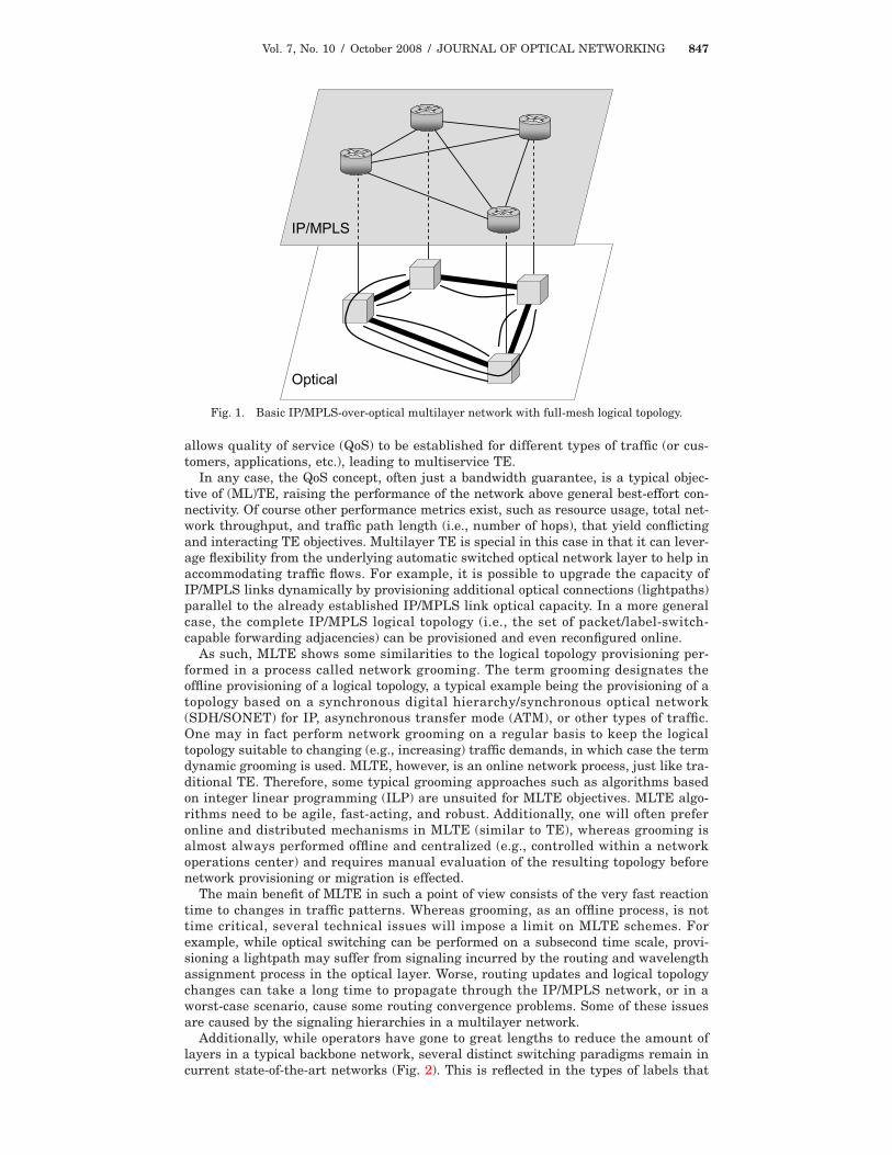
Originally, single-wavelength point-to-point fibers were used to carry trafficbetween IP routers. The arrival of WDM technology has vastly increased the availablecapacity on a single fiber, far beyond bandwidths manageable by a single optical linecard. Concatenating fiber wavelength channels into paths through an optical network(lightpath) allows traffic to bypass intermediate nodes in the IP domain. A lightpathestablishes a direct connection [forwarding adjacency in generalized MPLS (GMPLS)[1] terminology] between two IP routers. The set of configured forwarding adjacenciesis called the IP/MPLS logical topology (Fig. 1). The term IP/MPLS link will be used forthese forwarding adjacencies in the remainder of this text.
Fast switching optical technology [e.g., based on microelectromechanical systems(MEMS), etc.] enables dynamic configuration of such lightpaths, as opposed to themanual configuration of bypasses using, for example, optical patches. Architecturessuch as the automatic switched optical network (ASON) [2] and GMPLS help stan-dardize this optical layer flexibility and integrate it into the general networking infra-structure, using the tried label switching concept. As such, the optical technologydomain becomes a true configurable networking layer, built upon the physical layer.
Multilayer traffic engineering (MLTE), like traditional IP layer traffic engineering,optimizes some performance metric of the network by acting upon the traffic flowsoffered to the network. First, such traffic flows need to be identified. This can be doneby separating the packet IP traffic into flows based on Transmission Control Protocol(TCP) connections, based on hashing algorithms on the IP packet header, based on IPnode pair matching, based on MPLS labels [a label switched path (LSP)], etc. Second,the (ML)TE acts on the identified traffic flows. Most often, a specific route is given topackets belonging to a certain flow; however, TE can also consist of traffic shaping byrate limiting (or dropping) some flows. Some TE algorithms will classify traffic intoseveral traffic classes and perform distinct TE actions on each of those classes. This
1536-5379/08/100846-15/$15.00 © 2008 Optical Society of America
Vol. 7, No. 10 / October 2008 / JOURNAL OF OPTICAL NETWORKING 847
allows quality of service (QoS) to be established for different types of traffic (or cus-tomers, applications, etc.), leading to multiservice TE.
In any case, the QoS concept, often just a bandwidth guarantee, is a typical objec-tive of (ML)TE, raising the performance of the network above general best-effort con-nectivity. Of course other performance metrics exist, such as resource usage, total net-work throughput, and traffic path length (i.e., number of hops), that yield conflictingand interacting TE objectives. Multilayer TE is special in this case in that it can lever-age flexibility from the underlying automatic switched optical network layer to help inaccommodating traffic flows. For example, it is possible to upgrade the capacity ofIP/MPLS links dynamically by provisioning additional optical connections (lightpaths)parallel to the already established IP/MPLS link optical capacity. In a more generalcase, the complete IP/MPLS logical topology (i.e., the set of packet/label-switch-capable forwarding adjacencies) can be provisioned and even reconfigured online.
As such, MLTE shows some similarities to the logical topology provisioning per-formed in a process called network grooming. The term grooming designates theoffline provisioning of a logical topology, a typical example being the provisioning of atopology based on a synchronous digital hierarchy/synchronous optical network(SDH/SONET) for IP, asynchronous transfer mode (ATM), or other types of traffic.One may in fact perform network grooming on a regular basis to keep the logicaltopology suitable to changing (e.g., increasing) traffic demands, in which case the termdynamic grooming is used. MLTE, however, is an online network process, just like tra-ditional TE. Therefore, some typical grooming approaches such as algorithms basedon integer linear programming (ILP) are unsuited for MLTE objectives. MLTE algo-rithms need to be agile, fast-acting, and robust. Additionally, one will often preferonline and distributed mechanisms in MLTE (similar to TE), whereas grooming isalmost always performed offline and centralized (e.g., controlled within a networkoperations center) and requires manual evaluation of the resulting topology beforenetwork provisioning or migration is effected.
The main benefit of MLTE in such a point of view consists of the very fast reactiontime to changes in traffic patterns. Whereas grooming, as an offline process, is nottime critical, several technical issues will impose a limit on MLTE schemes. Forexample, while optical switching can be performed on a subsecond time scale, provi-sioning a lightpath may suffer from signaling incurred by the routing and wavelengthassignment process in the optical layer. Worse, routing updates and logical topologychanges can take a long time to propagate through the IP/MPLS network, or in aworst-case scenario, cause some routing convergence problems. Some of these issuesare caused by the signaling hierarchies in a multilayer network.
Additionally, while operators have gone to great lengths to reduce the amount oflayers in a typical backbone network, several distinct switching paradigms remain incurrent state-of-the-art networks (Fig. 2). This is reflected in the types of labels that
Optical
IP/MPLS
Fig. 1. Basic IP/MPLS-over-optical multilayer network with full-mesh logical topology.

Vol. 7, No. 10 / October 2008 / JOURNAL OF OPTICAL NETWORKING 848
can be used in GMPLS. In the remainder of this paper, we will assume an IP/MPLS-over-optical network. The layer 2 framing used in the network stack will remain outof scope but can, for example, be Ethernet. IP/MPLS logical link capacities will havethe provisioned optical lightpath bandwidth, i.e., 1 Gbit/s, 10 Gbits/s (correspondingto Ethernet standards), but may also be 2.5 Gbits/s, 40 Gbits/s, etc., depending on theexact optical transponder technology.
Also, networks can be separated into several network planes, as shown in Fig. 3 forthe IP/MPLS network layer. We can identify the data plane and control plane. Thedata plane carries and processes the actual network payload, i.e., user data. The con-trol plane consists of all control functions such as routing protocols. For the IP/MPLSlayer, these consist typically of OSPF [3], which is used to construct shortest-path con-nectivity automatically, and of course MPLS, which is used to set up to control labelswitched paths (LSPs). The routers may run the Resource Reservation Protocol withextensions for traffic engineering (RSVP-TE) [4] to manage the MPLS label distribu-tion.
The control plane also includes monitoring functionality, such as traffic measure-ment. For other network layers, other types of control plane functions are required.For example, the optical layer has routing (e.g., neighbor discovery) and reservationprotocols such as routing and wavelength assignment (RWA). Interlayer functions,such as the user-network interface (UNI), allow optical connections to be requestedfrom the IP/MPLS layer. Each network layer may include a separate control plane;however, standardization efforts such as GMPLS propose an integrated control planetaking care of all control functions of the multilayer network. In this paper, however,we will concentrate on IP/MPLS layer control plane issues, more specifically on trafficmeasurement and routing policies.
First, traffic measurement can be performed in multiple ways. We will focus on twomethods. A first method uses basic IP/MPLS interface monitoring to establish theactual load on each IP/MPLS link in the logical topology. A second method collectsMPLS reservation requests into a database to calculate a theoretical link occupancyvalue for each link. Of course this latter method requires MPLS functionality and,more specifically, for all traffic to be carried in LSP tunnels.
IP
Physical layer
OTH
ATM
SDH/SONETEthernet
MPLS
TCP/UDP TCP/UDP flow
HierarchicalLSP flow
LSP flow...
Forwardingadjacency
IP headerIP
Physical layer
OTH
ATM
SDH/SONETEthernet
MPLS
TCP/UDP TCP/UDP flow
HierarchicalLSP flow
LSP flow...
Forwardingadjacency
IP header
Fig. 2. Network layers.
data plane
control plane
Fig. 3. Network planes for the IP/MPLS layer.

Vol. 7, No. 10 / October 2008 / JOURNAL OF OPTICAL NETWORKING 849
Second, the term routing policy is used to indicate the type of routing that is incor-porated into the MLTE scheme. Each layer in Fig. 2 has its own specific properties asfar as routing and forwarding are concerned. Routing actions may be performed onTCP/User Data Protocol (UDP) flow, LSP, or IP/MPLS forwarding adjacency granular-ity.
This paper will focus on IP/MPLS measurement and routing granularity issues andtheir effect on MLTE performance. To this end we present in Section 2 a MLTEscheme that can naturally operate in several routing granularity modes. In Section 3we look at how measurement inaccuracies degrade MLTE throughput. Section 4describes an evaluation scenario to extract and discuss some routing granularity per-formance metrics.
2. Multilayer Traffic Engineering SchemeMultilayer traffic engineering consists of multiple interdependent mechanisms, suchas routing, online grooming, logical topology construction, and capacity adjustment.These mechanisms can be implemented and combined in various ways. For example,in related literature, [5] presents an integrated routing approach across IP/MPLS andWDM layers. Multilayer routing there is performed by considering a single graphmodel. The mechanism provides both dynamic grooming and shared protection formultilayer networks. Reference [6] presents the concept of lightpath fragmentationand defragmentation, which tries to solve the logical topology construction problemthrough finding optimal optical-electronic-optical termination nodes for optical con-nections.
In [7], MLTE is separated into long-term offline logical topology design versusshort-term, fast-responding online dynamic routing and capacity adjustment mecha-nisms. A straight-forward approach [8] establishes high and low traffic watermarks onlinks that are used as decision triggers to start a logical topology reconfiguration.
This section outlines the proactive MLTE strategy [9–11] and algorithm that will beused in some performance studies in Sections 3 and 4, paying special attention to howthe strategy relies on traffic measurement and how different types of routing tech-niques and associated routing granularities fit in with this scheme.
2.A. MLTE MechanismsRegardless of the specific MLTE scheme utilized, some basic mechanisms becomeapparent. First, capacity needs to be allocated in order to carry the offered traffic. Sec-ond, routes need to be assigned so this traffic has paths over the logical topology. Therouting mechanism builds on MPLS or OSPF, etc., functionality that is present also innetworks with a static IP/MPLS topology. We will classify the allocation of opticalcapacity into lightpaths that either change the logical topology (i.e., IP/MPLS routeradjacencies are modified) or only upgrade existing IP/MPLS logical links (i.e., addi-tional optical bypasses between already adjacent routers).
It should be noted that in terms of network stability and convergence, these mecha-nisms have very different time constants. Logical link capacity upgrades or down-grades are available immediately, limited only by optical layer switching and connec-tion establishment times. Rerouting traffic in the MPLS (and especially IP) layershould be done carefully to counter instability issues. Logical topology reconfigurationtakes a long time to converge, as it interacts with the routes of many traffic flows.
2.B. Routing Cost FunctionSince the underlying switched optical layer in an IP/MPLS-over-optical network isassumed to be fully flexible, the goal is to leverage this property in order to providecapacity only where needed. To this end a worst-case overprovisioning scenario is con-sidered: a logical topology that is a full mesh. Starting from this, we attempt to reducethe logical topology into fewer IP/MPLS links, while still being able to accommodatethe offered traffic.
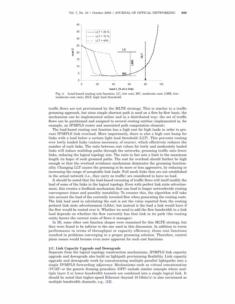
The logical topology and flow routing part of the presented strategy is combinedinto a single mechanism by using shortest-path routing under a load-based routingcost (Fig. 4) [9]. This cost is such that, when flows (regardless of their granularity) arerouted over a full mesh, links will remain unused, effectively reducing the mesh intoa sparser topology. The routing cost is used so that full-mesh links not carrying any
Vol. 7, No. 10 / October 2008 / JOURNAL OF OPTICAL NETWORKING 850
traffic flows are not provisioned by the MLTE strategy. This is similar to a trafficgrooming approach, but since simple shortest path is used on a flow-by-flow basis, themechanism can be implemented online and in a distributed way: the set of trafficflows can be partitioned and assigned to several routing entities (implemented in, forexample, an IP/MPLS router and associated path computation element).
The load-based routing cost function has a high cost for high loads in order to pre-vent IP/MPLS link overload. More importantly, there is also a high cost bump forlinks with a load below a certain light load threshold (LLT). This prevents routingover lowly loaded links (unless necessary, of course), which effectively reduces thenumber of such links. The ratio between cost values for lowly and moderately loadedlinks will induce multihop paths through the networks, grooming traffic onto fewerlinks, reducing the logical topology size. The ratio in fact sets a limit to the maximumlength (in hops) of such groomed paths. The cost for overload should further be highenough so that the overload avoidance mechanism dominates the grooming function-ality. Changing LLT causes the grooming to be more or less aggressive, by reducing orincreasing the range of acceptable link loads. Full mesh links that are not establishedin the actual network (i.e., they carry no traffic) are considered to have no load.
It should be noted that the load-based rerouting of traffic flows will itself modify theload of some of the links in the logical topology. Even with perfect link state advertise-ment, this creates a feedback mechanism that can lead to longer networkwide routingconvergence times and possibly instability. To counter this, the algorithm will takeinto account the load of the currently rerouted flow when generating the routing costs.The link load used in calculating the cost is not the value reported from the routingprotocol link state advertisement (LSAs), but instead is the load a link would have ifthe flow would be routed over it. Whether we need to add the flow bandwidth to a linkload depends on whether the flow currently has that link in its path (the routingentity knows the current route of flows it manages).
In [9], some other cost function shapes were examined for this MLTE strategy, butthey were found to be inferior to the one used in this discussion. In addition to worseperformance in terms of throughput or capacity efficiency, those cost functionsresulted in problems converging to a proper grooming solution. Therefore, controlplane issues would become even more apparent for such cost functions.
2.C. Link Capacity Upgrade and DowngradeSeparate from the logical topology construction mechanisms, IP/MPLS link capacityupgrade and downgrade also build on lightpath provisioning flexibility. Link capacityupgrade and downgrade work by concatenating multiple parallel lightpaths into asingle IP/MPLS forwarding adjacency. Mechanisms such as virtual concatenation(VCAT) or the generic framing procedure (GFP) include similar concepts where mul-tiple layer 2 or lower bandwidth tunnels are combined into a single logical link. Itshould be noted that higher-speed Ethernet (beyond 10 Gbits/s) is also envisioned asmultiple bandwidth channels, e.g., [12].
0
5
10
15
20
25
30
35
40
0 20 40 60 80 100
load L (%of a link)
costC
LLT = 20 %LLT = 10 %LLT = 40%
HLT
LC
MC
LMR
Fig. 4. Load-based routing cost function. LC, low cost; MC, moderate cost; LMR, low–moderate cost ratio; HLT, high load threshold.

Vol. 7, No. 10 / October 2008 / JOURNAL OF OPTICAL NETWORKING 851
In the previous cost function discussion, it was assumed that link loads areexpressed as a percentage of an IP/MPLS link. For example, if no on-demand upgrademechanism is available, then at most one lightpath can be establish between twoIP/MPLS routers. In such a case 100% link load corresponds to the full capacity of alightpath, 2.5 Gbits/s, 10 Gbits/s, etc. Usually, link loads should not be allowed toexceed 80% or so in order to avoid packet loss caused by router buffering problems orsmall-time-scale traffic peaks (load measurements will always entail some averaging).When router connectivity consists of either one or no lightpath, we can see problemsarise for very large traffic demands. The logical topology mesh explodes andapproaches a full mesh. In most high-traffic scenarios, however, some high-trafficnodes or links can still be identified. Additionally, high-node-degree logical topologiesare unrealistic because this requires a large number of router interfaces (line cards),which have to be installed beforehand of course and cannot be provisioned on demand.A sparser mesh is more suitable in this case; this can be implemented by using thelink upgrade and downgrade mechanism [11]. The 100% in this case corresponds tothe capacity delivered by the maximum number of parallel lightpaths. This typicallydepends on the technology used. An example would be a logical link concatenation ofup to four 2.5 Gbits/s lightpaths; in that case 100% means 10 Gbits/s.
2.D. Optical MetricsThe routing cost function as such does not take into account the physical layer. Thismeans that choices in logical topology design may result in suboptimal provisioning inthe optical layer. For example, the logical topology may be constructed such that manylong lightpaths need to be established unnecessarily. When taking the physical layer(i.e., fiber lengths, topology, etc.) into account, the logical topology more closelyresembles the physical topology, which yields better optical resource usage.
The network scenario envisioned in designing the MLTE strategy is an overlay orpossibly an augmented network. Overlay networks separate network layers into dis-tinct entities, limiting the information exchange between layers. This may be done fortechnological reasons (manageability) or confidentiality issues, etc. Physical and opti-cal layer information is brought into the MLTE strategy, or rather, the routing costfunction, by using an optical metric.
The optical metric consists of a value for each IP/MPLS router pair (similar to thefull mesh of link loads), which is reported from the optical layer. For example, themetric discussed in [10] is linear with the optical layer hop count (of a lightpath con-necting the IP/MPLS router pair in question). The optical metric allows the opticalresource usage to be reduced significantly. The metric is multiplied by the routing costfunction to assign the shortest path routing cost for the MLTE strategy. Setting opti-cal metric parameters (in this case the slope and Y-axis intercept of the linear opticalhop count function) pushes optimization more or less toward optical resource usage;this is an operator-settable parameter.
3. Traffic MeasurementsThe proactive MLTE strategy basic mechanisms require accurate knowledge of thetraffic load in IP/MPLS links (which are supported through optical layer lightpaths).The load is used in a cost function used by a shortest-path algorithm in order to routeIP/MPLS traffic flows as well as construct the IP/MPLS logical topology. In an idealsituation where the effect of (re)routing an IP/MPLS flow on the IP/MPLS link loadsis considered to be known immediately, the MLTE strategy can converge very fast; inmost cases, we found that the routing and logical topology will have stabilized as soonas each IP/MPLS flow has been routed once. Normally, a full mesh of IP/MPLS flowsis considered, representing the traffic matrix over the IP/MPLS nodes.
In a realistic and therefore suboptimal case where link state updates are nonin-stantaneous, convergence slows down, and the algorithm may need to cycle throughthe routing process several times (routing each flow multiple times).
3.A. Network Load MeasurementsLooking at how load can be extracted from the network, two main methods can beidentified, the ideal and the instant-knowledge case. First, load can be measureddirectly on the IP/MPLS router interfaces and flooded over the network. Second, load

Vol. 7, No. 10 / October 2008 / JOURNAL OF OPTICAL NETWORKING 852
can be inferred from monitoring traffic flows at ingress points. The first method is howone would flood IP/MPLS link state information using, for example, the OSPF proto-col.
The second method requires traffic monitoring for each of the IP/MPLS flows (theminimum number of flows being a full mesh between the IP/MPLS routers), but alsokeeping track of the routes of such flows, in order to derive IP/MPLS link loads. Thisinformation is used in the MLTE strategy. In the case of a centralized mechanism pro-viding IP/MPLS routes and logical topology updates, flow routes can be stored, andflow bandwidth requested from the ingress IP/MPLS routers. In a distributed case,these bandwidths and routes will need to be flooded over the network, since, forexample, MLTE processing of flows is then performed by the ingress node itself.
3.B. Simulation and Study SetupTo evaluate the effect of these control plane limitations, the MLTE simulation envi-ronment was altered such that delays in link state advertisement were taken intoaccount.
Both the direct interface measurement method and the flow-based method wereexamined. For the simulation run, the 14 node, 21 span NSFNET topology was used(Fig. 5), with uniformly distributed traffic matrices. Volumes of the traffic matrices(versus IP/MPLS link or lightpath capacity) were such that a range of sparselythrough densely meshed logical topologies were set up by the MLTE strategy.
A Java-based simulation environment was used that allows these traffic patterns tobe applied on the proposed physical topology. The environment includes discrete eventtechniques in order to simulate distributed control plane behavior. However, the dataplane itself is not modeled on a low level; that is, we did not use packet simulation.Instead, the traffic patterns are abstracted as a set of traffic flows with a source, des-tination, and bandwidth requirement. The MLTE strategy is then simulated by set-ting up logical topology links and assigning routes to these flows in the simulatedIP/MPLS-over-optical network. The environment runs as a single process (on one PC).
3.C. Effect of the Logical Topology Mesh SizeThe effect of control plane limitations is dependent on the meshedness of the logicaltopology (or similarly, the volume of traffic demands). A densely meshed networkoffers more capacity but also caters to more diverse traffic patterns. A more sparselymeshed logical topology will be highly optimized by the MLTE strategy toward thespecific traffic pattern. This means that for sparser topologies, greater (relative)changes occur in the IP/MPLS logical topology when traffic patterns shift. In suchcases, the traffic measurement delays prove to be problematic. Here we have intro-duced minimal delay into a flow-based measurement regime and examined the perfor-mance effect for various mesh sizes; in Subsection 3.D we look at sensitivity to largerdelays.
In Fig. 6, the throughput of traffic demands offered to the IP/MPLS layer is shownagainst offered traffic volume (relative percentage). As mentioned in [10], mesh size(number of logical topology mesh edges) is almost linear with increasing traffic vol-ume, until a full mesh is reached. A full mesh in this simulation case requires 91 linksto connect 14 nodes. The 100% traffic volume is the case where throughput degrada-tion is no longer seen (a volume corresponding to a topology roughly 2/3 of a fullmesh). Throughput is measured against the ideal measurement scenario, where no
Fig. 5. NSFNET 14 node, 21 span topology.

Vol. 7, No. 10 / October 2008 / JOURNAL OF OPTICAL NETWORKING 853
traffic is lost. Since in a network with multihop flow routes, loss in a link or a trafficflow will influence loss in other links and flows, traffic loss was determined by itera-tive approximation [11,13].
This means that for delayed measurements, some severe throughput degradation isseen around 50% traffic volume, i.e., a topology corresponding to 1/3 of a full mesh,and in the 14 node network case, this is therefore approximately 30 IP/MPLS (bidirec-tional) links. For very sparse meshes (approaching a spanning tree, 14 links), whichappear for loads of �50% relative, the logical topology becomes such that all trafficpatterns can be carried on the mesh, even for suboptimal routes; for low volumes, thelogical topology becomes more and more overprovisioned. This explains the higherthroughput seen for low traffic volumes.
3.D. Effect of Delayed Traffic MeasurementsIn any case, for the regular operating range of MLTE, that is, somewhere between aspanning tree and a full-mesh topology, some problems arise when control plane mea-surement delays are taken into account. These are caused by inaccurate IP/MPLSflow route assignments that lead to nonoptimally filled as well as overloaded IP/MPLSlinks. We examine the delay duration effect for the worst-case mesh size (i.e., approxi-mately 1/3 of a full mesh, as suggested by Fig. 4).
In Fig. 7, total traffic demand throughput is plotted against the measurement inter-val. The measurement interval is the time between two global IP/MPLS network loadmeasurements (i.e., link state flooding). Throughput results for both the flow-basedmethod and the link-based (direct interface measurement) method. An interval dura-tion of 10 corresponds to the lifetime of one traffic pattern; after that, a new trafficpattern is offered and the MLTE strategy will reconverge flow routes and logical topol-
0.75
0.8
0.85
0.9
0.95
1
30 40 50 60 70 80 90 100traffic (relative %)
throughput
0
20
40
60
80
100
meshsize
ThroughputMesh size
measuring intv. = 0.1
Fig. 6. IP/MPLS flow throughput versus traffic volume.
0.4
0.5
0.6
0.7
0.8
0.9
0.01 0.1 1 10measurement interval
throughput
flow basedlink based
at least one LSA floodper node reroute event
Fig. 7. Influence of measurement rate on throughput.

Vol. 7, No. 10 / October 2008 / JOURNAL OF OPTICAL NETWORKING 854
ogy. The IP/MPLS routing and logical topology construction process requires periodi-cally rerouting the flows. This process is run distributed; this means that each nodeby itself will periodically reroute flows it has been assigned. Flows have been assigneduniformly, and node reroute events are also spread out uniformly in time. In the simu-lation study, the time between two node reroute events is approximately 0.17 (all 14nodes are processed 4 times during the 10 s duration).
On the graph, one notices that results for both measuring methods are similar formeasurement intervals beyond these 0.17 time units. Throughput also degradesquickly beyond this point. This suggests that at least one networkwide measurementevent needs to be performed for each node reroute event. This allows for accurateinformation to be available as the time flows are rerouted.
However, even for measurement intervals shorter than 0.17 time units, throughputstill does not reach 100%. For these interval ranges, a discrepancy is noticed for bothmeasurement methods, with the flow-based method enabling better throughput fig-ures. This is as expected, since the flow-based method delivers accurate informationbased on flow bandwidth aggregation, which is what the MLTE strategy was origi-nally designed for. The link-based method takes into account traffic loss through thenetwork, and therefore the measurements themselves are inaccurate from a traffic-engineering standpoint. For example, the flow-based method may aggregate to linkloads of �100%, whereas actual link measurement will always return values of�100%, which underestimates network overload events and degrades the MLTEstrategy’s performance.
One also sees that throughput drops again for very short measurement intervals.Presumably, this is because in those cases some instability effects will arise betweenflow rerouting events within a single node. Also, some aliasing effects arise betweenthe measurement rate and the rerouting rate.
Concerning scalability, larger networks will have more routing nodes. Therefore, toconverge traffic within a similar duration of absolute time, more routing events needto occur per time unit. This will pose stronger constraints on measuring rates. Addi-tionally, more traffic flows are processed during each routing event (number of flowprocesses being proportional to the network node count as well); this will furtheraffect the sensitivity of the MLTE algorithm to inaccurate measurements.
4. Routing GranularityThe term routing granularity is used to indicate a characteristic of the routing policythat is incorporated into the MLTE scheme. Each layer has its own specific propertiesas far as routing and forwarding are concerned. Single TCP or UDP flows may in factbe assigned a unique route. This is done in applications using overlay networks (over-laid over the IP network) that employ their own hop-by-hop forwarding on top of theregular Internet. As mentioned before, IP header information may be used in classicTE, for example, to establish load-balancing flows over multiple parallel pathsthrough an IP network. As these techniques acting on layer 3 and up are more thedomain of single-layer TE or user-level optimization, these will not be considered.
In the layer stack, between layer 3 (IP, packet) and layer 2 (switching and framing),there is a so-called layer 2.5 that has traditionally been implemented using ATM. TheInternet Engineering Task Force (IETF) MPLS scheme offers many of the same ATMconcepts in a transparent manner. The ATM virtual channel identifier (VCI) and vir-tual path identifier (VPI) concepts can be mimicked using LSPs. In fact there is a pos-sibility to encapsulate hierarchical LSPs themselves into LSPs. This offers a widerrange of flow granularities when using MPLS-based routing policies. In any case,MPLS allows decoupling forwarding and routing, similar to ATM. Each LSP flow (i.e.,with a unique separate label) can be assigned its own route or path through the net-work. Label switching routers are usually integrated with IP routing capability into asingle electrical domain IP/MPLS node that is both packet and label switch capable.
In the IP/MPLS logical topology (which in fact implements a dynamic layer 2), eachlogical link (or forwarding adjacency) can be assigned a coarse granularity routingweight [14] (or cost), such as done in, e.g., OSPF. This allows some rudimentary TEpossibilities at link granularity.
4.A. Routing Granularity in MLTEThe MLTE strategy will be evaluated by offering traffic arrivals to be routed over thenetwork. Each traffic arrival is represented as a traffic flow. Depending on the group-

Vol. 7, No. 10 / October 2008 / JOURNAL OF OPTICAL NETWORKING 855
ing of the set of flows, MLTE routing will have a finer or coarser granularity. The fin-est granularity is achieved by considering each flow individually.
When the number of flows is high, this requires a lot of processing. To alleviate this,we can group all flows between the same IP/MPLS router pair into a single node pairmaster flow. For example, we can encapsulate all LSP flows between a node pairinside a master LSP (i.e., a higher hierarchy LSP tunneling the lower hierarchy LSPflows). In that case, we only need to manage at most a full mesh of IP/MPLS masterLSPs.
Last, a routing policy coupling forwarding and routing delivers very coarse routinggranularity by using traditional link weights (cf. traditional TE). In this case, there isno control over individual flows.
In Fig. 8, flow routes for these three routing policies and associated granularitiesare shown as an example. In the per-flow case (fine granularity MPLS policy), wehave individual control over each flow. For example, we can choose to route the twoA–C flows in different directions over the logical topology ring in an attempt to loadbalance traffic (similar for the two B–C flows). For the per-pair case (coarser granular-ity MPLS), all traffic flows between a node pair take the same path. However, we canstill load balance traffic: B–C traffic is routed in the opposite direction of A–C traffic.In the per-link case (OSPF-style policy) finally, only link weights can be set. If weassume all link weights are equal (shortest-path routing), we get the routing as shownin the figure. Segment B–C can possibly become overloaded as all traffic takes theshortest path. One may try adjusting the weights on the ring segments to betterspread traffic; for example, one could assign a high weight to segment A–B (whichwould cause flow A–C to be routed counterclockwise instead). However, weight settingmay interact with the path of other traffic flows, so this is nontrivial. In any case,routing granularity is clearly coarse in this case.
4.B. Evaluation ScenarioWe will evaluate the presented MLTE strategy for the three routing granularities.The per-flow and per-pair modes can be implemented simply by having the MLTEalgorithm route either every individual traffic arrival or an aggregated master trafficflow per node pair.
The per-link mode, which is based on link weights, can be implemented by directlyusing the cost function as, e.g., OSPF routing weights in the logical topology. Notethat since the cost function depends on the link load (and therefore on the routes ofthe traffic), we have to first converge those flow routes in an offline process (i.e., with-out actually modifying routes on the actual network). The resulting link weights canthen be assigned to the actual IP routing tables in the network simulation (no MPLSfunctionality will be used in the per-link case).
The 14 node, 21 edge NSFNET network was again used for the simulation study, asin Section 3. Because this section of the paper discusses interaction between IP/MPLSand the optical layer and is not limited to the IP/MPLS logical topology constructionas in Section 3, we will include an optical metric in the MLTE strategy. This metric isthe generic optical-hop-count-based linear metric with a slope of 1 (that is, the nodepair cost equals the number of optical hops connecting the pair). We refer to [10] formore information on optical metrics and their influence on optical layer resourceusage.
4.C. TrafficTraffic arrivals were generated with exponentially distributed interarrival and servicetimes. To vary traffic demand, the mean interarrival time was modulated according toa day–night rhythm. In this case, a simple sinusoidal variation was used, with the
CB
A
CB
A
CB
A
CB
A
CB
A
CB
A
Per flow Per pair Per linkFig. 8. Example flow routes for several routing granularities.

Vol. 7, No. 10 / October 2008 / JOURNAL OF OPTICAL NETWORKING 856
highest demand during peak hours (e.g., 8 p.m.). Parameters were chosen such thatlow-demand periods (mornings) have a total demand of one tenth of the peak load.
Service times were not modulated but chosen so that the required number of trafficarrivals was generated for a simulation (taking into account the bandwidth of a traf-fic arrival). For the peak traffic demand, traffic between two nodes was chosen to be30% of the lightpath capacity (i.e., 3 Gbits/s for 10 Gbits/s lightpaths). This choiceoperates the peak traffic demand very close to saturated logical topology links for theper-flow mode.
For the aggregate routing modes that reroute periodically, we chose a 15 min inter-val between routing updates. Traffic service (or holding) times were of the order of afew minutes. We will examine the performance of the three routing granularitymodes, looking at IP layer and optical layer effect.
4.D. Effect on IP Layer PerformanceFirst in Fig. 9 the number of overloaded (load higher than 80%, as per the cost func-tion) IP/MPLS links is shown versus the offered traffic demand (scaled where 1.0 isthe peak load). Results show averages extracted from a sufficient number of logicaltopologies generated by the MLTE strategy for each traffic volume. Note that even forsimilar volumes, actual traffic matrices may be quite different. Comparing per-flowand per-pair modes, one notices a penalty of approximately five additional overloadedlinks that is fairly independent of the offered load. This aggregation penalty is causedby the less efficient TE as flows between two nodes always need to follow the sameroute in the per-pair mode.
Next, when comparing per pair and per link, the overload penalty appears to growwith increasing traffic. This is a degrooming penalty as traffic flows can no longer berouted individually over the network. This causes traffic to group together over a fewheavily loaded IP/MPLS links, whereas the other TE modes have the option to spreadtraffic over the network, increasing logical topology meshing. This problem is espe-cially apparent at high loads.
4.E. Effect on Optical Resource UsageNext, the average number of required lightpaths (versus load) is shown in Fig. 10,again for the three MLTE granularity modes. We have opted to enable the link capac-ity upgrade and downgrade mechanism in this case, with the assumption that theIP/MPLS link overload can be solved by establishing an additional overload lightpathparallel to the overloaded IP/MPLS link.
Note the fact that the per-link scheme requires fewer lightpaths than the per-pairmode. This is not too surprising, given the fact that the per-link mode concentratesoverload in a few high-capacity backbone IP/MPLS links (which will have very highoverload). Overload lightpath filling will be much more efficient consequently, explain-ing the apparently low number of required lightpaths.
0
5
10
15
20
25
0 0.2 0.4 0.6 0.8 1load (scaled)
#overloaded
links
Per flowPer pair
Per link
Fig. 9. Number of overloaded links versus load.

Vol. 7, No. 10 / October 2008 / JOURNAL OF OPTICAL NETWORKING 857
Then we break down the required lightpaths in regular and overload lightpaths. Weshow the total amount of required optical capacity for a simulation run of one week�168 h� in Fig. 11. Results are shown as lightpath hours; one lightpath hour corre-sponds with one lightpath’s worth of capacity being required during 1 h.
For the per-flow scheme, fewer than 1 in 1000 lightpath hours were set up to solvethe overload (not visible in the figure). We have chosen traffic demands to remain inthe nonoverloaded case for the per-flow mode, as said before. Some heavily loaded(over 80%) IP/MPLS links were experienced, but very few IP/MPLS links exceed 100%load (saturation).
The other two MLTE modes have a significant amount of overload capacity thatneeds to be established. Implementing a link capacity upgrade and downgrade schemecan probably only be rationalized when the upgrade and downgrade have a suffi-ciently large range in capacities to set up. Using upgrade and downgrade only to solvethe overload (which comes with inefficient link filling) will not be very reasonable.Consequently, one should not expect overload capacity upgrade and downgrade to beavailable in realistic networks, and in fact all traffic in such overload lightpaths wouldto be lost.
Conversely, link capacity upgrade and downgrade is more typically suitable inmultilayer networks with a lower multiplexing factor, i.e., lower lightpath capacitiesversus typical IP/MPLS bandwidths. For optical networks with lower lightpathcapacities, even typical network operation will require setting up parallel lightpathsto carry all IP/MPLS traffic between two nodes. The availability of link capacityupgrade and downgrade offers finer granularity control over the IP/MPLS link band-
0
10
20
30
40
50
60
70
80
0 0.2 0.4 0.6 0.8 1load (scaled)
numberoflightpaths
per flowper pairper link
Fig. 10. Number of lightpaths.
0
1000
2000
3000
4000
5000
6000
7000
8000
9000
per flow per pair per link
numberoflightpathhours
overload lightpathsregular lightpaths
Fig. 11. Number of lightpath hours.
Vol. 7, No. 10 / October 2008 / JOURNAL OF OPTICAL NETWORKING 858
width and more efficient link filling. A drawback consists of the technological require-ments for such a scheme (e.g., flexible IP/MPLS router interfaces and optical tran-sponders).
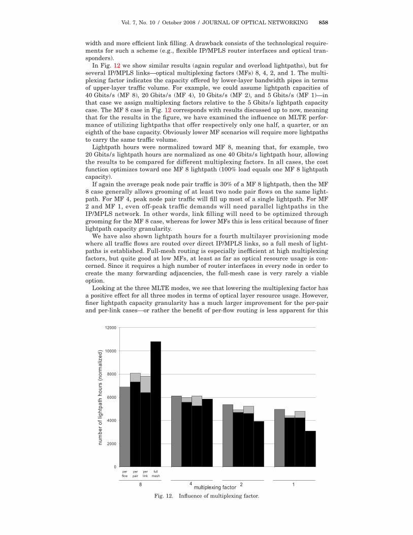
In Fig. 12 we show similar results (again regular and overload lightpaths), but forseveral IP/MPLS links—optical multiplexing factors (MFs) 8, 4, 2, and 1. The multi-plexing factor indicates the capacity offered by lower-layer bandwidth pipes in termsof upper-layer traffic volume. For example, we could assume lightpath capacities of40 Gbits/s (MF 8), 20 Gbits/s (MF 4), 10 Gbits/s (MF 2), and 5 Gbits/s (MF 1)—inthat case we assign multiplexing factors relative to the 5 Gbits/s lightpath capacitycase. The MF 8 case in Fig. 12 corresponds with results discussed up to now, meaningthat for the results in the figure, we have examined the influence on MLTE perfor-mance of utilizing lightpaths that offer respectively only one half, a quarter, or aneighth of the base capacity. Obviously lower MF scenarios will require more lightpathsto carry the same traffic volume.
Lightpath hours were normalized toward MF 8, meaning that, for example, two20 Gbits/s lightpath hours are normalized as one 40 Gbits/s lightpath hour, allowingthe results to be compared for different multiplexing factors. In all cases, the costfunction optimizes toward one MF 8 lightpath (100% load equals one MF 8 lightpathcapacity).
If again the average peak node pair traffic is 30% of a MF 8 lightpath, then the MF8 case generally allows grooming of at least two node pair flows on the same light-path. For MF 4, peak node pair traffic will fill up most of a single lightpath. For MF2 and MF 1, even off-peak traffic demands will need parallel lightpaths in theIP/MPLS network. In other words, link filling will need to be optimized throughgrooming for the MF 8 case, whereas for lower MFs this is less critical because of finerlightpath capacity granularity.
We have also shown lightpath hours for a fourth multilayer provisioning modewhere all traffic flows are routed over direct IP/MPLS links, so a full mesh of light-paths is established. Full-mesh routing is especially inefficient at high multiplexingfactors, but quite good at low MFs, at least as far as optical resource usage is con-cerned. Since it requires a high number of router interfaces in every node in order tocreate the many forwarding adjacencies, the full-mesh case is very rarely a viableoption.
Looking at the three MLTE modes, we see that lowering the multiplexing factor hasa positive effect for all three modes in terms of optical layer resource usage. However,finer lightpath capacity granularity has a much larger improvement for the per-pairand per-link cases—or rather the benefit of per-flow routing is less apparent for this
0
2000
4000
6000
8000
10000
12000
perflow
perpair
perlink
fullmesh
multiplexing factor
numberoflightpathhours(normalized)
8 4 2 1
Fig. 12. Influence of multiplexing factor.

Vol. 7, No. 10 / October 2008 / JOURNAL OF OPTICAL NETWORKING 859
case. These modes drop below the per-flow mode in terms of total required lightpathhours once it is no longer necessary to groom multiple flows together in order to fill upa lightpath. Grooming (and specifically fine granularity grooming in the per-flow case)solves suboptimal link filling and provides load balancing using the IP/MPLS costfunction. Lower MFs, however, intrinsically solve link filling inefficiency; also, loadbalancing, while helping with IP/MPLS throughput, increases the load in the opticallayer of the network, as it routes traffic over longer paths. Since lower-capacity light-paths lead to better link filling, the need for fine granularity (per flow) load balancingor rather the goal of creating some uniform load in all IP/MPLS links as suggested bythe cost function diminishes; in fact it only hurts optical layer resource usage.
Interestingly, it seems that the ratio of overload versus total lightpath hours dimin-ishes with lower MFs. This is again because overload lightpaths typically have badlightpath filling efficiency. Wasted capacity can be reduced then by using lower-capacity lightpaths. Note, however, that it still may not be possible to create overloadlightpaths because of router interface or optical transponder limitations. Again theoverload traffic may be lost, despite the good optical performance of the per-pair andper-link modes for low MFs.
5. ConclusionsControl plane issues for MLTE have been examined in two separate aspects: trafficmeasurement and path assignment.
For realistic, nonideal traffic measurement, measurement delays due to the distrib-uted nature of network link load extraction were found to be an issue. They degradetotal demand throughput for typical operating modes of MLTE, i.e., moderately denselogical topology meshes. Measurement methods using direct per-link interface moni-toring were found to perform worse than methods that aggregate per-flow bandwidthinformation extracted from IP/MPLS ingress nodes in order to derive logical topologylink loads.
For the path assignment aspect of the control plane, several routing policies exist inconsidering traffic flows offered to a multilayer network. Flows can be considered indi-vidually, aggregated per IP/MPLS node pair, or one can rely solely on OSPF-style linkweight setting, leading to distinct granularities in routing assignment. The suitabilityof MLTE modes with specific routing granularities depends on the multiplexing factor.For networks with coarse granularity (i.e., high capacity) lightpaths, fine granularityrouting granularities solve the inefficient link filling optimally through multihop traf-fic grooming. For networks with finer granularity (low-capacity) lightpaths, link fillingoptimization and the fine granularity load-balancing properties of the grooming partof the MLTE strategy become less of an issue. Instead, such networks lean more onthe link capacity upgrade and downgrade functionality in addition to grooming.
AcknowledgmentsThis work was partially funded by the European Commission through the projectsIST-NOBEL II under contract FP6-027305 and the Network of Excellence BONE, aswell as by the Flemish Government through the Fonds voor WetenschappelijkOnderzoek–Vlaanderen (FWO) project 3G057808. B. Puype thanks the Institute forthe Promotion of Innovation through Science and Technology in Flanders (IWT-Vlaanderen) for its financial support through his Ph.D. grant.
References1. E. Mannie, ed., RFC3945: Generalized Multi-protocol Label Switching (GMPLS)
Architecture (Network Working Group, 2004).2. ITU-T G.8080/Y.1304, Architecture for the Automatically Switched Optical Network (ASON)
(International Telecommunication Union Telecommunication Standardization Sector, 2001).3. J. Moy, RFC2328: OSPF Version 2 (Network Working Group, 1998).4. D. Awduche, L. Berger, D. Gan, T. Li, V. Srinivasan, and G. Swallow, RFC3209: RSVP-TE:
Extensions to RSVP for LSP Tunnels (Network Working Group, 2001).5. T. Cinkler and Cs. Gáspár, “Fairness issues of routing with grooming and shared
protection,” in Proceedings of the 8th IFIP Working Conference on Optical Network Designand Modelling (ONDM 2004) (Kluwer, 2004), pp. 665–668.

Vol. 7, No. 10 / October 2008 / JOURNAL OF OPTICAL NETWORKING 860
6. T. Cinkler, G. Geleji, M. Asztalos, P. Hegyi, A. Kern, and J. Szigeti, “�-path fragmentationand de-fragmentation through dynamic grooming,” in Proceedings of the 2005 7thInternational Conference on Transparent Optical Networks (IEEE, 2005), pp. 1–4.
7. P. Iovanna, R. Sabella, and M. Settembre, “A traffic engineering system for multilayernetworks based on the GMPLS paradigm,” IEEE Network 17(2), 28–37 (2003).
8. B. Gillani, R. Kent, and A. Aggarwal, “Topology reconfiguration mechanism for trafficengineering in WDM optical network,” in Proceedings of the 19th Symposium on HighPerformance Computing Systems and Applications (2005), pp. 161–167.
9. B. Puype, Q. Yan, D. Colle, S. De Maesschalck, I. Lievens, M. Pickavet, and P. Demeester,“Multi-layer traffic engineering in data-centric optical networks, illustration of concepts andbenefits,” in Proceedings of COST266/IST OPTIMIST Workshop—7th IFIP WorkingConference on Optical Network Design and Modelling (ONDM 2003) (Kluwer, 2003), pp.211–226.
10. B. Puype, Q. Yan, S. De Maesschalck, D. Colle, K. Steenhaut, M. Pickavet, A. Nowé, and P.Demeester, “Optical cost metrics in multi-layer traffic engineering for IP-over-opticalnetworks,” in Proceedings of the 2004 6th International Conference on Transparent OpticalNetworks (IEEE, 2004), pp. 75–80.
11. B. Puype, D. Colle, M. Pickavet, and P. Demeester, “Influence of multilayer trafficengineering timing parameters on network performance,” in IEEE International Conferenceon Communications (IEEE, 2006), pp. 2805–2810.
12. H. Toyoda, S. Nishimura, M. Okuno, K. Fukuda, K. Nakahara, and H. Nishi, “100-Gb/sphysical-layer architecture for next-generation ethernet,” IEICE Trans. Commun. E89B,696–703 (2006).
13. E. Van Breusegem, B. Puype, D. Colle, J. Cheyns, M. Pickavet, and P. Demeester,“Evaluation of ORION in predimensioned networks,” in Proceedings of the 19thInternational Teletraffic Congress (Springer, 2005), pp. 1265–1274.
14. B. Fortz and M. Thorup, “Optimizing OSPF/IS—IS weights in a changing world,” IEEE J.Sel. Areas Commun. 20, 756–767 (2002).